rocketry: system development experience and student outreach
TRANSCRIPT
Proceedings of the 2004 American Society for Engineering Education Annual Conference & Exposition
Copyright © 2004, American Society for Engineering Education
Rocketry: System Development Experience and Student Outreach
Timothy S. Hunt, David P. Miller, Eduardo Ortega, and Alfred G. Striz
School of Aerospace and Mechanical Engineering
University of Oklahoma
Norman, Oklahoma
Abstract
Rocketry can provide students with exciting and stimulating opportunities to advance their
systems engineering and design/manufacturing/programming skills. During the last 2 years, an
11 ft tall minimum-diameter aluminum rocket has been developed and instrumented in the
School of Aerospace and Mechanical Engineering at the University of Oklahoma, sponsored by
OSIDA, the Oklahoma Space Industry Development Authority. It is propelled by a N-size solid
rocket engine and is expected to climb to about 22,000 ft with a maximum speed of Mach 1.5.
The instrumentation includes an accelerometer, temperature and pressure sensors to measure the
location and behavior of the shock wave during the supersonic flight phase, and strain gauges for
the determination of the structural behavior of the rocket. This rocket was finally launched in
November of 2003.
At various times during the planning, assembly, and instrumentation phases of the project,
participants included local high school students, college students from sophomores to graduates,
and an OU alumnus with high-power rocketry experience. Students participated in various ways:
on a voluntary basis, by signing up for a ‘Special Project’ course, or under grant support. The
effort was well documented and can easily be repeated at other educational institutions.
At the same time, a student outreach activity took place, involving model rocketry. A senior from
OU, again under the Special Projects course designation, was involved in a local model rocket
mini course effort, covering various high schools in the Oklahoma City area. The students were
exposed to the engineering and scientific aspects of model rocketry and to the design and
construction of their own rockets to given specifications, culminating in a final competition.
Thus, in this learning-by-teaching environment, the College student benefited as much from the
effort as the high school students who were exposed to a wide variety of engineering principles.
High-Powered Rocketry
A couple of years ago, one of our alumni mentioned an interesting ongoing dispute: where on a
high-powered rocket in supersonic flight does the shock wave occur and how hot does the rocket

Proceedings of the 2004 American Society for Engineering Education Annual Conference & Exposition
Copyright © 2004, American Society for Engineering Education
body become from friction heating? We recognized this as an exciting potential student project
and sought and received funding for it from OSIDA, the Oklahoma Space Industry Development
Authority. Once the initial design requirements for the high-powered rocket had been laid out: to
find the location of the shockwave on the rocket, to determine its skin temperature, and to gain
some understanding of the structural behavior of the rocket during supersonic flight, it became
clear that we had to work with a metal rocket to be able to install reasonable sensors for data
acquisition. We decided on using aluminum for minimum weight. Reaching supersonic speeds
would only be possible if we used a large motor (N-size) in a minimum diameter casing.
Mechanical Aspects
Since time constraints prevented us from manufacturing our
own rocket, we purchased the main mechanical pieces of the
minimum-diameter N-size rocket system from Dr. Rocket, an
on-line retailer who specializes in custom high-power rocketry.
These pieces were then modified to meet the needs of our
proposed experiments.
The original cut line between the nosecone and the main trunk
of the rocket was the only place that the original rocket
separated. Our specifications required the rocket to break down
into three sections: an instrumentation bay attached to the
nosecone, an altimeter bay with housings for the para-
chutes, and a lower interface that connected to the motor. Upon
Figure 1. The Rocket determining the amount of space needed for the equipment in
each section to ensure a successful launch, test, and recovery, it
was noted that a second piece of the outer trunk was necessary for our rocket system. Dr. Rocket
was able to supply the required addition
Modifications were relatively simple for the outer trunk of the rocket. Both tubes were cut in
specific locations to provide the required lengths for the three sections of the rocket. The
nosecone was then attached to the end of one tube. At the opposite end of this tube, a stationary
parachute lug was installed along with an eyebolt to serve as the interface between the upper
section of the rocket and the altimeter section via the shared parachute. Aluminum tubing was
machined from rough stock to serve as the sliding couplers between each of the three sections.
These couplers were fixed-mounted in the altimeter (or middle) section of the rocket. The
addition of these couplers and a parachute lug on each side created a cell within this section
where the three redundant altimeters could function without being exposed to high pressures
from the nosecone or parachute deployment.
The nosecone underwent the most significant changes in the rocket structure. It was ported to
allow measurements of the outside pressure profile during flight. A hole, approx 0.064-inch in
diameter, was drilled through the tip of the nosecone. This through hole was met by a 0.250-inch
hole from the backside of the nosecone while taking care not to penetrate the outermost surface
of the nosecone. The stair-stepped-hole allowed a larger hose to measure the pressure at a
localized point on the surface of the nosecone.
Proceedings of the 2004 American Society for Engineering Education Annual Conference & Exposition
Copyright © 2004, American Society for Engineering Education
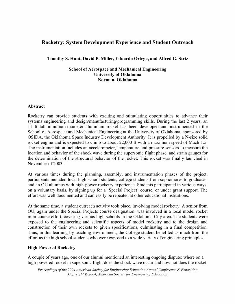
Figure 2: Mechanical Example - Altimeter Bay Assembly
The process was repeated several times down the side of the nosecone. Each additional hole was
positioned in a spiral pattern, which radiated back away from the tip of the nosecone, to insure
that measurement ports would not disrupt airflow to ports downstream.
A shortage of high-power solid rocket motors from Aerotech induced a search for another
supplier. Upon finding a source for a motor, we were informed that the internal pressures from
the new propellant would be higher than the specifications of our current motor housing. This
resulted in the need for a stronger motor casing. The new supplier fabricated this casing such that
it could utilize the existing interface to the rest of the rocket system.
Electronic Aspects
It was decided that the data acquisition equipment should consist of an accelerometer and a set of
pressure and temperature sensors as well as strain gauges along the forward body of the rocket.
These would all record to two data loggers, with the data to be downloaded after retrieval of the
rocket. The biggest obstacle to our data acquisition efforts was the shortage of inexpensive
electronic equipment with sufficient performance specs to perform the required measurements in
the hostile environment of supersonic flight. These analog measurements were to be converted to
digital signals and stored in two on-board data recorders. This left us to design and build all of
our own circuit boards for the electronic system within the rocket. The tasks of developing a list
of requirements that met the needs of both the sensors and the digital–to-analog converter (DAC)
proved to be very time consuming. Schematics for the thermocouples and strain amplifiers were
found in technical guides from Analog Devices. In a similar source, schematics were found for
the use of the Motorola accelerometers and pressure sensors, which were modified for their
intended use in our rocket system. From the schematics, layouts for the circuit boards were
generated and transferred to an outside manufacturer who “burnt” the circuit boards. The rest of
the components were soldered to the circuit boards, and the boards were tested. Each of the

Proceedings of the 2004 American Society for Engineering Education Annual Conference & Exposition
Copyright © 2004, American Society for Engineering Education
Figure 3: Electronics Example - Pressure Sensor and Accelerometer Boards
circuits was calibrated to establish baselines for the sensor behavior. In order to protect the
boards during flight, cradles were designed to serve as the mounting interface between the circuit
boards and the metal exterior of the rocket.
Integration and Shakedowns
Large design projects such as this high power rocketry endeavor offer a secondary challenge to
those who are involved in the individual development of the mechanical and electronic
components, namely the integration of all components into a functional whole. Throughout the
construction phase, various subsystems were assembled and disassembled to verify that the
proper integration goals were being met. This repetitious build and teardown gave the students
participants a thorough understanding of the rocket and instrumentation system.
As the project neared the end of the construction and testing phase, the group moved on to
complete rocket system assembly and shakedown trials. This started with the selection of three
dates to serve as progress checks, leading up to the launch. On these dates, the rocket system,
including the launch pad, would be erected in a manner that closest resembled the teams needed
actions on the day of the launch. Ultimately, these meetings provided a chance to catch unmissed
errors in system integration and allowed a launch day checklist to be critiqued.
Launch Day
After exhaustive testing of components, subsystems, and the rocket as
a whole, 25,000 ft FAA waivers were activated at a secure launch site,
the Municipal Airport in Sayre, Oklahoma, for the weekend following
Thanksgiving 2003. The day before the scheduled launch, we
transported the rocket and the necessary launch gear to Sayre. The
airport had been used numerous times before as a site for rocket
launches by local Oklahoma rocketry clubs; therefore, it was
advantageous for us to utilize the existing working relationships
despite the two hours to transport the needed equipment.
The morning of the launch began with the erection of the launch
tower. Immediately following, the team took to the delicate tasks of
prepping the rocket for launch. This stage required the initialization of
the data loggers, the folding of the parachutes, and the arming of the

Proceedings of the 2004 American Society for Engineering Education Annual Conference & Exposition
Copyright © 2004, American Society for Engineering Education
pyrotechnics used for separating the three segments of the rocket: the motor casing, the altimeter
segment, and the instrumentation section. As one of the final prep stages, the N-class motor was
installed into the motor casing. Due to the cold weather, the rocket subsystems were assembled
in and near a hangar at the airport. Then, the rocket was transported the short distance from the
hangar to the launch pad in three sections, and was assembled on the pad. There, the igniter was
placed into the motor section. The focus then turned to securing the launch site: all spectators
were asked to retire to the “minimum safe distance” zone, 1,000 ft from the launch tower. After
final inspections, the igniter was attached to the power leads from the control launch box.
Following a 10 second countdown, a 2-year investment had a flawless liftoff with the
experimental motor, a rewarding sight for those who had worked so long and hard on the project.
However, we were now left with the task of waiting for the deployment of the parachutes and the
recovery that should shortly follow. The deployment could easily be seen with the naked eye.
However, it took place somewhat early in the flight plan. This led us to believe that the rocket
may have gone horizontal at altitude due to weathervaning in high winds. This would have
caused the altimeters to sense no change in altitude without any knowledge of the actual speed of
the rocket. Such an altimeter reading would then cause the drogue chute to deploy. If the rocket
were still traveling at high speed, this improper deployment could cause a catastrophic failure in
the attachment, the lines, or the chute itself. As it were, our team spent the remainder of the
afternoon searching for any sign of the rocket.
This chain of events provided important lessons concerning high-powered rocketry. The major
lesson was the fact that a failure can, at times, be a more powerful learning tool then a success.
Instantly, we focused on everything that could have gone wrong, which provided our team with
much information through brainstorming. Although we were greatly disappointed with the loss
of the rocket, the wealth of information gained was quite valuable. In addition, such a failure also
gives designers a chance to see where their egos may have blinded them. Our rocket system
included a 90-mile line-of-sight transponder. An over-zealous engineer may think that the
recovery of the rocket was a ‘sure thing’. This ‘sure thing’ may prevent one from doing the
‘obvious thing’, such as including contact information on the rocket segments. We found out that
the ‘sure thing’ may not work as designed when other subsystems fail to do their job or a
scenario has been overlooked. Here, we learned that the recovery transponder and receiver are
temperamental when exposed to any combination of gullies and high voltage transformers. A
couple of times during the recovery phase, our team found themselves chasing false signals due
to the electromagnetic fields surrounding the high voltage transformers in the surrounding
landscape. To add to our frustration, gullies or any other obstructions to the line of sight with the
rocket greatly reduce the range and the received signal strength from the actual transponder
located inside the rocket.
Structure and Student Involvement
The project was guided by the two Co-PIs and by two OU alumni, who brought high-power
rocketry experience to the team. Together, a focus was determined and held for the length of the
project by the team members.

Proceedings of the 2004 American Society for Engineering Education Annual Conference & Exposition
Copyright © 2004, American Society for Engineering Education
Graduate Level: A Graduate Assistant (GA) took on the task of managing the team’s day-to-
day activities. Project updates were continually discussed with the co-investigators and new
action items were generated. The GA was responsible for generating top-level constraints for
systems, and finding components that would be utilized to complete the required electronic
systems. In addition, he also served as the integrator for pieces that were farmed out to undergrad
team members. In numerous cases, he walked undergrads through the design process such that
they could achieve a better understanding of the overall project goals.
Undergraduate Level: Two different styles of undergraduate participation were tried during the
project. At the beginning, the project was opened up to a “club” environment. This style of
involvement taught us several lessons: The first and foremost problem is to keep everyone busy.
Students who were not directly involved soon lost interest. On the other hand, some students
were overwhelmed in the early stages of the project due to the number of unknowns involved in
achieving the projects goals. As the project progressed, the semester progressed as well. This
presented a second challenge because students had problems juggling final exams and class
projects with rocket tasks.
However, a second method of undergrad involvement proved to be more beneficial and more in
line with ABET’s previous endorsement of hands-on engineering project courses at OU, such as
SAE Mini-Baja, SAE Formula, Solar Car, etc. Students participating in the project through a
special projects course could receive a tangible form of reward, a grade. Thus, course
involvement could substitute for a variable number of hours, which would dictate the student’s
level of involvement, helping to lighten the load for a couple of seniors that still required
electives before graduation. In addition, it gave the co-investigators and the managing grad
student the ability to set a standard for quality of work acceptable for the project. Using this
approach, parts were designed, parts lists and assembly manuals for the rocket were compiled,
and performance calculations were made. Student learning was assessed through weekly
progress reports, presentations to the team, and through a final semester report.
High School Level: During the course of the project, high school students from a rocketry class
taught by one of the alums were brought in to participate in the discussions and in the design of
subsystems such as the launch tower. It was difficult to keep them involved, however, since they
were already over-committed due to extracurricular activities at the local high school.
Rocketry Outreach
With our rocketry outreach program, we want to expose local area high school students to the
importance and excitement of science and engineering in today’s world. The goal of the program
is to teach them the engineering concepts needed to safely design, construct, and competitively
fly the most effective model rocket. This is intended to prepare the students for such challenging
projects as the high-powered instrumented rocket described above and to encourage their pursuit
of science and engineering career fields after they leave high school. The outreach instructor is
normally an undergraduate student or a graduate student, who will take on this task for credit,
and will present a final report for a grade at the conclusion of the project.

Proceedings of the 2004 American Society for Engineering Education Annual Conference & Exposition
Copyright © 2004, American Society for Engineering Education
Purpose and Goals: For this project, the high school students are given a list of criteria their
rocket design has to meet in order to compete effectively with other teams. The responsibility of
the outreach instructor is to teach them the fundamentals of mathematics, physics, and
engineering as they pertain to model rocket design to ensure that their rocket’s flight will be safe,
stable, and successful. This allows us to prove to the students that mathematics is not just rote
recall and number crunching, but that it is an essential skill in engineering that can determine
whether their design is safe and stable or unsafe and unsuccessful. Along with the distributed
course material, the students are encouraged to do further research about model rocketry in order
to gain additional knowledge of the subject.
Teamwork: One important aspect in the field of science and engineering is the concept of
teamwork. For example, four teams of three and one team of four students were formed at a local
high school. A leader was chosen from each group and given the responsibility of dividing tasks
within the group and making sure that the tasks were completed on time. In each group, the
leaders should be those most knowledgeable in math and science or the most motivated.
Program Structure: The high school students are introduced to Newton’s Law of Motion,
Barrowman’s Equation for center of pressure, etc., and are provided with typical rocket flight
profiles and information on rocket motors, different types of drag, and design synthesis. They are
given a course packet, including instruction on how to calculate center of gravity, center of
pressure, lift, thrust, etc. Even though only a few students have the mathematical and science
background required for the project, they normally catch on quickly to the material. The only
major problem is that many students are committed to other science projects and, thus, have
limited time available during the semester.
After learning and understanding initial concepts, students are asked to design a rocket on paper,
including a component list and a 3-D drawing. This is combined with outside research and
continues until a reasonable design emerges. The design is taken to the Visual Center of Pressure
(VCP) software, which outputs data to determine if a rocket is safe. Each design is corrected as
necessary. The resulting rockets are built from kits given to each team. Finally, the WRASP
software is used to determine the projected altitude based on the F-20 engine provided to the
students. The rockets are launched, and the students finish up the project with a written and
graded report.
The outreach instructor then provides feedback on the project to his advisor at the University,
both verbal and through a written final report. It is difficult to track how the participating High
School students’ career field choices will be affected by such a project. Most of the participants
were Seniors with predetermined college plans. Nevertheless, we intend to finish future outreach
endeavors with surveys comparing attitudes towards science and engineering before and after the
project and with questions regarding college and career area selections.
Conclusions
The design, construction, instrumentation and launch of a minimum diameter high–powered
metal rocket provides an exciting means of teaching students from high school to graduate level
Proceedings of the 2004 American Society for Engineering Education Annual Conference & Exposition
Copyright © 2004, American Society for Engineering Education
project planning and coordination skills and giving them hands-on experience in mechanical and
electronic component design and manufacturing. It is a (hopefully) repeatable exercise that can
be implemented with the help of a local high-powered rocket club at most academic institutions.
Student outreach, such as the described rocketry class, can aid in giving undecided high school
students choices for a career in science and engineering, which they might otherwise never
consider. For the mentor, it allows for the development of leadership, group interaction, and
public speaking skills, while providing a venue to make a difference in a child’s life.
References
1. Striz, A.G., and Miller, D. P., Launch Vehicle Design, Instrumentation, and Data Evaluation. Final Report to
OSIDA, AME, University of Oklahoma, Norman, OK, December 20, 2002.
2. Ortega, E., Introduction to High Power Rocketry, Undergraduate Special Project Report, AME, University of
Oklahoma, Norman, OK, May 8, 2003.
Biographical Information
TIMOTHY S. HUNT
Mr. Hunt currently is a graduate student in the School of Aerospace and Mechanically Engineering at the University
of Oklahoma. His studies are in the field of intelligent robotics.
DAVID P. MILLER
Dr. Miller serves as the Wilkonson Professor of Intelligent Systems in the School of Aerospace and Mechanical
Engineering at the University of Oklahoma. His research interests include robotics technology - automated planning,
robotics, and communications with automated systems - and robotics as a mechanism for technology education - as
co-founder/CTO of the KISS Institute for Practical Robotics, which promotes technology education in K-20.
EDUARDO ORTEGA
Mr. Ortega graduated with a B.S. in Mechanical Engineering from the School of Aerospace and Mechanical
Engineering at the University of Oklahoma in the spring of 2003. He works for Tinker Air Force Base in Midwest
City, Oklahoma. This was his first exposure to student outreach.
ALFRED G. STRIZ
Dr. Striz serves as Professor and L.A. Comp Chair in the School of Aerospace and Mechanical Engineering at the
University of Oklahoma. He is the Associate Director for Research at OU for the Oklahoma NASA Space Grant
Consortium, and the Associate Director of the Center for Engineering Optimization in the College of Engineering.
His interests are in MDO, structural optimization, computational mechanics, and aeroelasticity.