rod-in-tie layout system - global product support · switch machine connecting rod area or even...
TRANSCRIPT

1000 Technology Drive, Pittsburgh, PA 15219 645 Russell Street, Batesburg, SC 29006 SM 9411
Copyright© 2009 SM 9411, Rev. 1 Ansaldo STS USA, Inc. December 2009
Rod-In-Tie Layout System
ASTS USA Part Nos.
X4928xx-xx
Installation
Maintenance


Notices
SM 9411, Rev. 1, December 2009 i
Proprietary Notice This document and its contents are the property of Ansaldo STS USA, Inc. (formerly known as Union Switch & Signal Inc., and hereinafter referred to as "ASTS USA"). This document is furnished to you on the following conditions: 1.) That no proprietary or intellectual property right or interest of ASTS USA is given or waived in supplying this document and its contents to you; and, 2.) That this document and its contents are not to be used or treated in any manner inconsistent with the rights of ASTS USA, or to its detriment, and are not to be copied, reproduced, disclosed or transferred to others, or improperly disposed of without the prior written consent of ASTS USA.
Important Notice ASTS USA constantly strives to improve our products and keep our customers apprised of changes in technology. Following the recommendations contained in the attached service manual will provide our customers with optimum operational reliability. The data contained herein purports solely to describe the product, and does not create any warranties.
Within the scope of the attached manual, it is impossible to take into account every eventuality that may arise with technical equipment in service. Please consult an ASTS USA local sales representative in the event of any irregularities with our product.
ASTS USA expressly disclaims liability resulting from any improper handling or use of our equipment, even if these instructions contain no specific indication in this respect. We strongly recommend that only approved ASTS USA spare parts are used as replacements.

Revision History
ii SM 9411, Rev. 1, December 2009
Revision History Rev. Date Nature of Revision
Original November 2005 Initial Issue of the Manual
1 December 2009 Revised Section 2.6.2 and Revised Figure 2-2

Table of Contents
SM 9411, Rev. 1, December 2009 iii
Table of Contents 1. INTRODUCTION ...............................................................................................................................1-1
1.1. Description................................................................................................................................1-1 1.2. Advantages...............................................................................................................................1-2
2. INSTALLATION.................................................................................................................................2-1 2.1. Site Preparation ........................................................................................................................2-1
2.1.1. New Panel Installations ................................................................................................2-1 2.1.2. Modifying an Existing Site.............................................................................................2-1
2.2. Equipment/Tools Required .......................................................................................................2-1 2.3. Parts to be Installed at Site.......................................................................................................2-2 2.4. Determining Tie No. 1 and Tie No. 2 ........................................................................................2-6 2.5. Installation Instructions .............................................................................................................2-6
2.5.1. Installation of RIT Assembly at the Site........................................................................2-6 2.6. Installation of the Switch Machine ..........................................................................................2-10
2.6.1. Setting the Switch Machine on the Support Ties (Figure 2-10)..................................2-10 2.6.2. Attaching the Lock Rod and Point Detector Rod (Figure 2-12)..................................2-12 2.6.3. Attaching the Operating Rod (Figure 2-13) ................................................................2-13
2.7. Attaching the Point Lugs to the Point Lock Hinge Lugs .........................................................2-14 2.7.1. Tie 1 ............................................................................................................................2-14 2.7.2. Tie 2 ............................................................................................................................2-15
2.8. Layout Adjustments ................................................................................................................2-16 2.8.1. Point Opening Adjustment ..........................................................................................2-16 2.8.2. Connecting Rod Adjustment.......................................................................................2-17 2.8.3. Point Bounce Limiter Adjustment ...............................................................................2-17
2.9. Install Covers (Figure 2-17) ....................................................................................................2-18 2.10. Switch Heaters........................................................................................................................2-19
2.10.1. Calrod Heaters............................................................................................................2-19 2.10.2. Blower Style Heaters ..................................................................................................2-20
2.11. Site Restoration ......................................................................................................................2-20 3. MAINTENANCE ................................................................................................................................3-1
3.1. Preventive Maintenance ...........................................................................................................3-1 3.1.1. Lubrication ....................................................................................................................3-2 3.1.2. Inspection......................................................................................................................3-2 3.1.3. Layout Inspection..........................................................................................................3-2 3.1.4. Switch Machine Inspection ...........................................................................................3-3
3.2. Periodic Maintenance ...............................................................................................................3-3 3.2.1. Cleaning........................................................................................................................3-3 3.2.2. Adjustment ....................................................................................................................3-3 3.2.3. Lubrication ....................................................................................................................3-3 3.2.4. Performance Testing ....................................................................................................3-3
4. PARTS LIST ......................................................................................................................................4-1 4.1. RIT Assembly N4928XXXX ......................................................................................................4-1 4.2. RIT Tie Assemblies...................................................................................................................4-3

Table of Contents
iv SM 9411, Rev. 1, December 2009
4.3. Connecting Rods in the Ties ....................................................................................................4-5 4.4. Optional Heater Wiring .............................................................................................................4-6
5. TECHNICAL SUPPORT....................................................................................................................5-1
List of Figures Figure 1-1. RIT Layout ..............................................................................................................................1-1 Figure 2-1. Area Under the Rails Dug Out and Prepared for Installing the RIT Assembly ......................2-2 Figure 2-2. Assembled Rods in the Ties...................................................................................................2-3 Figure 2-3. Point Lug Mounting Hardware................................................................................................2-4 Figure 2-4. Machine Mounting Hardware .................................................................................................2-5 Figure 2-5. Orientation of Tie 1 and Tie 2 for Right Hand Layout.............................................................2-6 Figure 2-6. Installation Bracket .................................................................................................................2-7 Figure 2-7. Installation Bracket In Place for Installing the RIT Assembly.................................................2-8 Figure 2-8. RIT Assembly Being Hoisted to Slide Under Rails.................................................................2-8 Figure 2-9. Sliding RIT Assembly Under Rails .........................................................................................2-9 Figure 2-10. Mounting the Switch Machine on the Support Ties............................................................2-11 Figure 2-11. Specific Mounting Holes in the Base of the “M” Style Switch Machine..............................2-11 Figure 2-12. Lock Rod Assembly and Point Detector Bar Assembly .....................................................2-13 Figure 2-13. Operating Rod/Basket ........................................................................................................2-13 Figure 2-14. Point Lug Mounting Hardware............................................................................................2-15 Figure 2-15. Point Lugs Attached to the Points ......................................................................................2-16 Figure 2-16. Point Bounce Limiter ..........................................................................................................2-18 Figure 2-17. Covers on the RIT Assembly..............................................................................................2-19 Figure 2-18. Electrical Connection for Calrod Heater.............................................................................2-19 Figure 4-1. Rod-in-Tie Typical Layout ......................................................................................................4-2 Figure 4-2. Tie Assemblies .......................................................................................................................4-4 Figure 4-3. Assembled Rods in the Ties...................................................................................................4-6 Figure 4-4. Calrod Heater Wiring in Tie ....................................................................................................4-7

Table of Contents
SM 9411, Rev. 1, December 2009 v
List of Tables
Table 2-1. Point Lugs and Hardware Kit (X49200010) (Figure 2-3)........................................................2-4 Table 2-2. Machine Mounting Hardware (X49200006) (Figure 2-4) .......................................................2-5 Table 3-1. Preventive Maintenance Schedule.........................................................................................3-2 Table 4-1. Parts List for RIT Assembly....................................................................................................4-1 Table 4-2. Parts List for the Tie Assemblies............................................................................................4-3 Table 4-3. Parts List for the Connecting Rods.........................................................................................4-5 Table 4-4. Parts List for the Calrod Heater..............................................................................................4-6

Table of Contents
vi SM 9411, Rev. 1, December 2009

Introduction
SM 9411, Rev. 1, December 2009 1-1
1. INTRODUCTION
The ASTS USA Rod-in-Tie (RIT) Layout replaces conventional wooden or concrete ties with hollow metal ties to support the ASTS USA “M” style switch machines. The hollow ties allow the switch machine connecting rods to be inside the ties. This provides a more stable switch machine layout, minimizes maintenance, and enables track personnel to perform their maintenance activities without the typical concern for the switch machine connecting rods.
The RIT system has been designed to minimize the installation time and maintenance interval of a layout.
1.1. Description
The RIT consists of two hollow steel tie assemblies. The first or No. 1 Tie assembly houses the point detector and lock rod connecting rods along with a device that limits vertical point bounce. The second or No. 2 tie assembly houses the basket and the switch throw connecting rod. Both the No. 1 and No. 2 tie assemblies contain an adjustable spreader rod connected to a set of cast transition lugs that are assembled to a set of adjustable point lugs. The spreader rods are insulated on one side.
Figure 1-1. RIT Layout

Introduction
1-2 SM 9411, Rev. 1, December 2009
Tie plate assemblies are installed to each hollow steel tie using Huck captive fasteners. Gage insulators are used between the straight move and turnout side tie plates to assist in holding gage. To minimize installation time, both ties are pre-assembled to the level just described.
Specifications for the tie plates were provided by the user for a specific turnout installation. The tie plates are fabricated to conform to the angle of the rail in the turnout and are secured to the metal ties in precise locations to match the track.
The switch machine is mounted on two short hollow steel ties between four welded saddle blocks. These support tie sections are designed to accommodate various sizes of switch machine mounting hardware.
The design of the RIT system incorporates point bounce limiter blocks to minimize the vertical movement of the switch points. The No. 1 Tie assembly is equipped with two point bounce limiter blocks which are adjustable to work with various switch-point bolt-hole elevations. After the four point lugs are fastened to the switch points, the point bounce limiter blocks are adjusted to provide a 1/4” gap between the underside of the block and the top of the spreader rod. This minimizes the vertical movement of the switch points during train movement over the layout.
To minimize maintenance on the layout, the RIT uses the Nord-Lock® bolt securing system instead of traditional lock washers in some areas. These lock washers have proven to provide better resistance to the loosening of the nuts due to vibration. To take full advantage of this securing system the nuts and bolts need to be torqued to the proper values at installation. In addition to the Nord-Lock washers, cotter pins are also used as a backup method of securing this hardware.
The RIT is manufactured to accept two different heater configurations. Either the Calrod or blower style heaters can be used in the ties.
1.2. Advantages
The RIT design provides several advantages over traditional type layouts.
• As wood ties deteriorate, layout components become loose requiring more frequent maintenance. The RIT design, because of its all-steel construction, holds the switch machine secure relative to the rail. This feature, along with using the “M” Style Switch Machine equipped with the “ECC” upgrade, will greatly reduce machine and layout maintenance.
• With all rod connections housed inside the hollow steel ties, the crib areas (spaces) between the ties can now be filled with ballast which further limits tie movement. By tamping in these areas at the time of installation an RIT layout will provide for ultimate layout stability.
• Existing equipment may be used. The RIT design is compatible with any “M” Style switch machine with threaded point detector bars and threaded “Y” end lock rods.

Introduction
SM 9411, Rev. 1, December 2009 1-3
• The ties have been designed to be compatible with standard tamping equipment. The tamping operation can now flow through a layout without needing to manually tamp the switch machine connecting rod area or even change the tamper settings.
• In addition, optional spreader rods are available for installation on top of the ties to replace the existing spreader rods in the crib area.

Introduction
1-4 SM 9411, Rev. 1, December 2009

Installation
SM 9411, Rev. 1, December 2009 2-1
2. INSTALLATION
NOTE As a general guideline for the procedures included in this section of the manual the Nord-Lock washers used in the RIT Assembly should be torqued to the following recommended torque values:
1/2” bolt 70.2 ft-lb
5/8” bolt 139 ft-lb
3/4” bolt 245 ft-lb
7/8” bolt 394 ft-lb
1” bolt 595 ft-lb
2.1. Site Preparation
2.1.1. New Panel Installations
There are no special site preparations required to install an RIT layout in a new installation. The road bed is prepared just as if standard ties were being used.
2.1.2. Modifying an Existing Site
When the RIT layout replaces an existing layout, the site must be prepared to accept the new metal ties. This is done by removing the existing switch machine from the ties and removing the two head block ties from under the rails. To install the new metal ties, the roadbed has to be trenched under the track at the location for the new ties to a depth of at least 15 inches below the bottom of the stock rail. In addition there must be at least 13 feet of open space to either side of the track (Figure 2-1) at the same approximate elevation as the removed roadbed under the rail. In some cases this may involve moving the junction box to gain the required clearance.
2.2. Equipment/Tools Required
A backhoe or other such device is recommended to maneuver the RIT assembly through the rails. In addition, it is recommended that a lifting device similar to a crane be available to assist in positioning the RIT assembly. Track jacks are also recommended for supporting the ties during the initial installation. Other than that, no special tools are required to install the RIT assembly layout. Standard track tools and standard hand tools are all that is required. A list of the recommended equipment and tools is presented below.
• Backhoe
• Speed Swing/Boom Truck

Installation
2-2 SM 9411, Rev. 1, December 2009
• Track Jacks
• Standard Track Tools
• Standard Hand Tools
Figure 2-1. Area Under the Rails Dug Out and Prepared for Installing the RIT Assembly
2.3. Parts to be Installed at Site
The ties are shipped separately with the spreader rods, point detector and lock rods, and switch throw connecting rod installed in the ties. For installation, the ties need to be assembled into a single unit using the installation bracket (PN M49206201) and the installation strap to hold and maintain the position of tie No. 2 relative to tie No. 1. It is recommended that the RIT layout be checked to ensure all of the parts are installed properly in the ties; the ties should be assembled as much as possible before being transported to the installation site.
The connecting rods, which are assembled and shipped in the ties, are shown in Figure 2-2. The point lug mounting hardware and the machine mounting hardware, which will be installed at the

Installation
SM 9411, Rev. 1, December 2009 2-3
site, are shown in Figure 2-3 and Figure 2-4, and listed in Table 2-1 and Table 2-2, respectively. In addition, four sets of rail braces, serrated washers, and Pandrol clips are provided for the tie plates.
Verify that all of the mounting hardware and rails connectors are available for assembly at the site.
BASKET
POINT LUGS
LOCK RODLUG
POINT DETECTOR LUG6A1.
0010
.00
Figure 2-2. Assembled Rods in the Ties

Installation
2-4 SM 9411, Rev. 1, December 2009
Table 2-1. Point Lugs and Hardware Kit (X49200010) (Figure 2-3) Item No. Description Part No.
201 Lug Clip Pin M49202801 202 Fitting , 1728-B Alem Drive Hydraulic J039139 203 Cotter Pin , 1/8 x 1-1/2 Spring Steel J048622 204 Point Lug M49201702 205 Bolt, 1”– 8 x 5” Long, Square Head M49208503 206 Washer, Flat 1-1/16” ID, 2” OD J4751200180 207 Washer, Lock , 1” Heavy J4751210146 208 Nut, 1” - 8 UNC 2B, Heavy J048117 209 Cotter Pin, 3/16” x 2” Spring Steel J048636 210 Adapter Plate w Studs Layout Specific 211 Bolt, 1” – 8 x 4-1/4” Long Square Head M49208501
Note: The parts listed are for 1” hardware, additional kits for 3/4” and 7/8” hardware are also available.
209
211
205
210 206
204
207
208
THROWHINGE LUG
POINT / LOCKHINGE LUG
203
202
201
Figure 2-3. Point Lug Mounting Hardware

Installation
SM 9411, Rev. 1, December 2009 2-5
Table 2-2. Machine Mounting Hardware (X49200006) (Figure 2-4) Item No. Part No. Quantity
101 Q49207504 4 102 J5000820180 4 103 J047506 4 104 J047772 4 105 J048026 4 106 J5001240274 4 107 J048029 4 108 J0477773 4
Note: The parts listed are for 3/4” hardware, additional kits for 7/8” and 1” hardware are also available.
105
104
103
TIE 2
SUPPORT TIE
TIE 1
106 108 107
101
102
Figure 2-4. Machine Mounting Hardware

Installation
2-6 SM 9411, Rev. 1, December 2009
2.4. Determining Tie No. 1 and Tie No. 2
The ties will be stamped “Tie 1” and “Tie 2.” This indicates how the ties are to be oriented in the assembly. Tie 1 will be the first tie encountered as the train approaches the points of the switch (Figure 2-5). This is a critical determination because the rail will not connect to the tie plates properly if the ties are reversed.
TIE 1
TIE 0
TIE 3
TIE 2
SUPPORT TIES
Figure 2-5. Orientation of Tie 1 and Tie 2 for Right Hand Layout
2.5. Installation Instructions
2.5.1. Installation of RIT Assembly at the Site
For installations replacing existing head block ties only, the area under the rails must be properly dug out to receive the RIT assembly (Section 2.1.2). Position the assembly so that it can slide under the rails. The assembly must be placed so that the switch machine end of the assembly is away from the track.

Installation
SM 9411, Rev. 1, December 2009 2-7
NOTE Ensure that the tie end covers (Item 16 of Figure 4-2) are installed prior to starting the installation process to avoid collecting any ballast in the ends of the ties. For installation the covers should be oriented and installed with the drainage holes in the upper portion of the tie end opening.
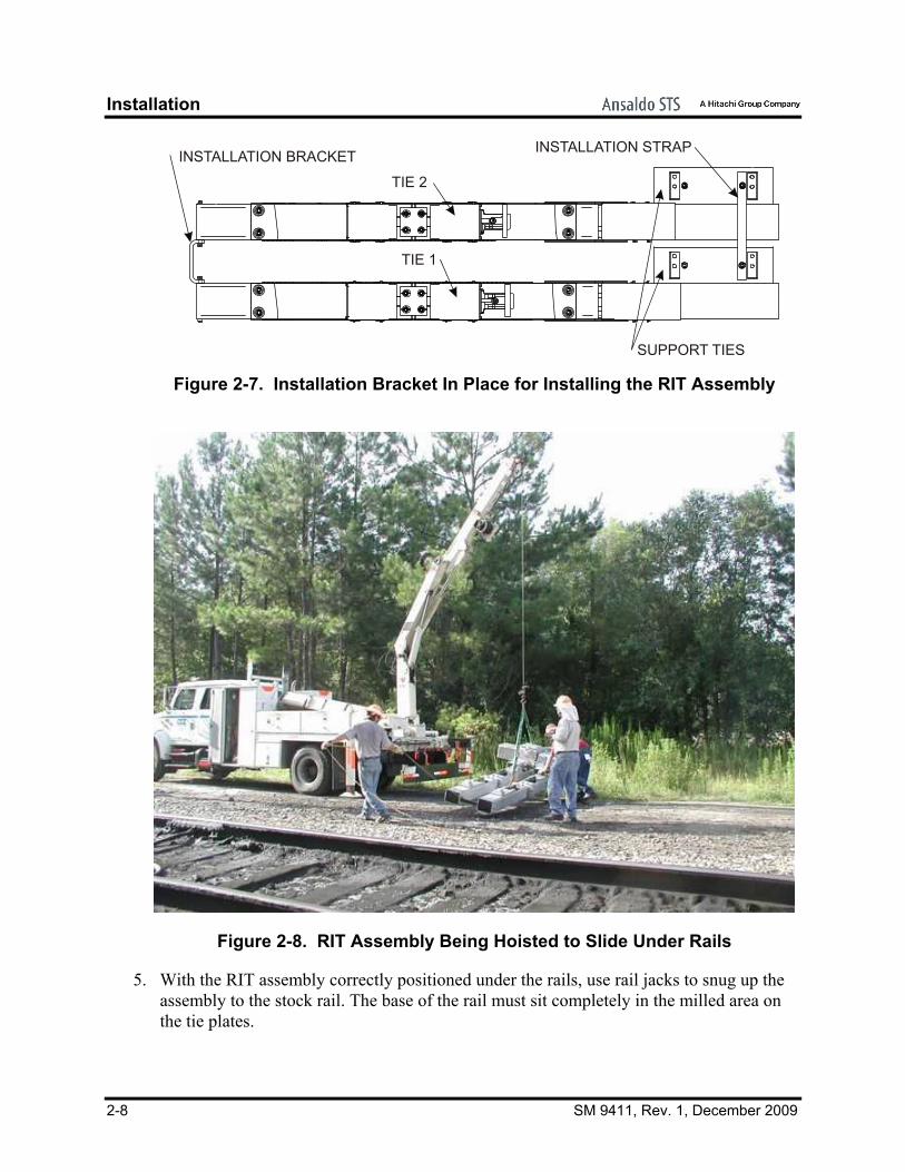
1. Remove the tie end cover from the end of both ties by removing the four 7/8” hex bolts and lock washers on either side of the ties. Rotate the end covers 180 degrees so that the drain holes are at the top of the tie opening and secure the end covers back into the ends of the ties. When the 7/8” hex bolts and lock washers are being replaced, install the installation bracket (Figure 2-6) to the ties as shown in Figure 2-7.
2. Attach a lifting strap to the installation bracket on the end of the RIT assembly and maneuver the strap under the rails to the far side of the rails.
3. Rig the RIT assembly so that it can be lifted slightly to facilitate maneuvering it under the rails (Figure 2-8).
NOTE Avoid dragging the ties through the ballast to prevent damage to the mesh on the ties.
4. Lift the RIT assembly just enough to get the weight of the assembly off of the ground and pull the RIT assembly under the rails (Figure 2-9). The assembly should be positioned so that the tips of the points lie approximately 1” back from the edge of the tie plates.
Figure 2-6. Installation Bracket
Installation
2-8 SM 9411, Rev. 1, December 2009
TIE 1
TIE 2
SUPPORT TIES
INSTALLATION BRACKET INSTALLATION STRAP
Figure 2-7. Installation Bracket In Place for Installing the RIT Assembly
Figure 2-8. RIT Assembly Being Hoisted to Slide Under Rails
5. With the RIT assembly correctly positioned under the rails, use rail jacks to snug up the assembly to the stock rail. The base of the rail must sit completely in the milled area on the tie plates.

Installation
SM 9411, Rev. 1, December 2009 2-9
6. Secure the tie plates to the stock rail with the supplied rail braces, serrated washers, and Pandrol clips.
NOTE Adjustment of rail gage may be required ahead and behind the RIT layout to facilitate proper fit of the rail to the tie plates.
7. Verify the rail gage.
8. Remove the tie end cover from the end of both ties by removing the four 7/8” hex bolts and lock washers on either side of the ties. Rotate the end covers 180 degrees so that the drain holes are at the bottom of the tie opening and secure the end covers back into the ends of the ties. When the 7/8” hex bolts and lock washers are being replaced, install the installation bracket to the ties as was done for the installation (Figure 2-7).
9. With the RIT assembly secured to the rails and the rail gage verified before and after the layout, reballast the ties (Section 2.11).
Figure 2-9. Sliding RIT Assembly Under Rails

Installation
2-10 SM 9411, Rev. 1, December 2009
2.6. Installation of the Switch Machine
NOTES 1. The RIT Assembly is compatible only with switch machines with
threaded point detector bars (PN N285906) and threaded “Y” end lock rods (PN N149866).
2. The point detector bar and lock rod assembly must be installed in the switch machine prior to assembly of the machine to the RIT.
With the RIT layout installed and secured to the rails, the switch machine can be installed.
2.6.1. Setting the Switch Machine on the Support Ties (Figure 2-10)
WARNING The M Style Switch and Lock mechanism weighs approximately 1000 pounds. It must be rigged for the lift in accordance with standard safety specifications and all railroad standards.
1. Rig the switch machine for lifting with a speed swing or boom truck.
2. Lift the switch machine and position it over the RIT assembly just above the support ties.
3. Slowly lower the switch machine so that it sits between the saddle blocks on the support ties, ensuring that the selected mounting holes in the base of the switch machine align with the mounting holes in the support ties. It is important that the correct holes in the switch machine base be used to maintain the proper relationship with the connecting rods in the main ties. The correct mounting holes in the base of the switch machine are shown in Figure 2-11.
4. Insert the bushing (Item 101) and the bolt (Item 102) up through the support tie mounting hole so that it goes in the switch machine base. Slide the washer (Item 103) and lock washer (Item 104) onto the bolt above the mounting base and secure them with the nut (Item 105). Repeat this process for the other three mounting holes in the support ties. Loosely tighten the mounting bolts.
5. With all four bolts secured through the support tie and the machine mounting base seated on the support ties, hand tighten the mounting bolts to secure the switch machine to the RIT assembly.
6. Install the bolts (Item 106), lock washers (Item 107), and nuts (Item 108) on the sides of the saddle blocks on the support ties. Do not tighten the bolts at this time.

Installation
SM 9411, Rev. 1, December 2009 2-11
105
104
103
TIE 2
SUPPORT TIE
TIE 1
106 108 107
101
102
Figure 2-10. Mounting the Switch Machine on the Support Ties
MOUNTING HOLES Figure 2-11. Specific Mounting Holes in the Base of the “M” Style Switch Machine

Installation
2-12 SM 9411, Rev. 1, December 2009
2.6.2. Attaching the Lock Rod and Point Detector Rod (Figure 2-12)
NOTES The RIT Assembly is compatible only with switch machines with threaded point detector bars and threaded “Y” end lock rods.
The point detector bar and lock rod assembly must be installed in the switch machine prior to assembly of the machine to the RIT.
Prior to installation of the connecting rods, confirm the following:
• Inside jam nut is positioned approximately 1 inch from the end of the rod threads.
• Graphite grease is generously applied between cast washers and all lug surfaces.
• Inside jam nut and full nut are tightened, activating the features of the Nordlock washer.
• The outer-most jam nut and full nuts are tightened, allowing a pivot-type motion of the connecting rod. There must be no lateral (lost motion) detected at any of the connecting rods.
• When tightening the outer-most jam nut, the position of its related full nut must be held to ensure pivot motion of the connecting rod.
The connecting rods are all assembled inside the ties and need to be attached to the rods in the switch machine. The first to be attached is the machine lock rod.
1. Manually cycle the switch machine until it is in mid-stroke.
2. Thread a jam nut (Item 15) and a heavy nut (Item 18) onto the switch machine lock rods. Thread them on with the flat side of the nuts facing away from the switch machine and towards the connecting rods.
3. Thread a jam nut (Item 15) and a cast nut (Item 14) onto the point detector rod on the switch machine. Thread them on with the flat side of the nuts facing away from the switch machine and towards the connecting rods.
4. Loosen the jam nut (Item 13), heavy nut (Item 17), and washer (Item 16) on either side of the lock rod lug casting (Item 4,) and on either side of the point detector lug casting (Item 5). Loosen the jam nut (Item 13), heavy nut (Item 17), and washer (Item 16) on either side of the lock rod lug casting (Item 4).
5. Align the “Y” end lock rods on the switch machine with the two holes in the lock rod lug casting (Item 4) and move the connecting rod assembly onto the switch machine rods.

Installation
SM 9411, Rev. 1, December 2009 2-13
6. Thread a jam nut (Item 15) and a heavy nut (Item 18) onto the switch machine lock rods. Thread them on with the flat side of the nuts facing away from the switch machine and towards the connecting rods.
7. Thread a jam nut (Item 15) and a cast nut (Item 14) onto the point detector rod on the switch machine. Thread them on with the flat side of the nuts facing away from the switch machine and towards the connecting rods.
14
15
18 15
1317 16 13 17 16
POINT DETECTOR LUG
SWITCH MACHINELOCK ROD ASSEMBLY
SWITCH MACHINE POINT DETECTOR BAR ASSEMBLY
LOCK ROD LUG
Figure 2-12. Lock Rod Assembly and Point Detector Bar Assembly
2.6.3. Attaching the Operating Rod (Figure 2-13)
Align the hole in the switch machine operating bar with the hole in the top flange of the basket (Item 32). Insert a 7/8” bolt (Item 11) into the hole in the basket. Place a washer (Item 9), lock washer (Item 10), and nut (Item 8) on the bolt and tighten the nut. Insert a cotter pin (Item 12) in the pin hole in the bolt under the operating rod nut.
12
111098
SWITCH MACHINE OPERATING BAR
BASKET
Figure 2-13. Operating Rod/Basket

Installation
2-14 SM 9411, Rev. 1, December 2009
2.7. Attaching the Point Lugs to the Point Lock Hinge Lugs With the RIT assembly installed and secured to the rails and the switch machine secured to the support ties and the connecting rods, attach the point lugs to the point lock hinge lugs using the hardware provided with the point lugs (X49200005) (Figure 2-14). The procedures are presented below.
NOTE Loosely assemble all point lug hardware prior to centering and final tightening.
2.7.1. Tie 1
1. On each side of Tie 1, position a point lug (Item 204) so that the holes in the yoke on the lug align with the hole in the upper end of the point lock hinge lug.
2. With the holes aligned, insert the lug clip pin (Item 201) into the holes from the top ensuring it is through both sides of the yoke on the point lug and extends out the bottom of the point lug. Insert a cotter pin (Item 203) into the hole on the bottom of the lug clip pin.
3. On both sides of Tie 1, position the point lug against the point rail and insert two bolts (Item 205) through the holes in the points and through the slots in the point lug.
4. Loosely secure the point lug to the point rail with washers (Item 206), lock washers (Item 207), and nuts (Item 208) on the two bolts.
5. Insert a cotter pin (Item 207) into the small hole in the bolts (Item 208) through the nuts (Item 206) to ensure the nuts do not back off.

Installation
SM 9411, Rev. 1, December 2009 2-15
209
211
205
210 206
204
207
208
THROWHINGE LUG
POINT / LOCKHINGE LUG
203
202
201
Figure 2-14. Point Lug Mounting Hardware
2.7.2. Tie 2
1. On each side of Tie 2 position the preassembled point lug and adapter assembly (Item 210) so that the holes in the yoke on the lug align with the hole in the upper end of the switch throw hinge lug.
2. With the holes aligned, insert a lug clip pin (Item 201) into the holes from the top ensuring it is through both sides of the yoke on the point lug and extends out the bottom of the point lug. Insert a cotter pin (Item 203) into the hole on the bottom of the lug clip pin.
3. On both sides of Tie 2, position the adapter plate (Item 210) against the rail and insert two bolts (Item 211) through the holes in the point rails and through the slots in the adapter plate.
4. Loosely secure the adapter plate to the point rail with washers (Item 206), lock washers (Item 207), and nuts (Item 208) on the two bolts.
5. Ensure the adapter plate is not binding anywhere.
6. Insert a cotter pin (Item 209) into one of the small holes in each stud of the adapter plate and the bolts (Item 205) through the nuts (Item 208) to ensure the nuts do not back off.

Installation
2-16 SM 9411, Rev. 1, December 2009
7. At this point the connecting rods in the RIT are secured to the points of the switch (Figure 2-15).
POINT / LOCKHINGE LUG
206
207
208
208
205
204
210206207
208
211
209
THROWHINGE LUG
204
210
206207
209
208
Figure 2-15. Point Lugs Attached to the Points
2.8. Layout Adjustments
WARNING When making adjustments to the layout, make sure the power is disconnected from the switch machine. Failure to do so could result in severe personal injury.
NOTE All switch machine and RIT hardware must be tightened prior to making any layout adjustments.
2.8.1. Point Opening Adjustment
Manually cycle the switch machine and confirm that the point opening dimension is as required by the layout drawings. This dimension is taken approximately 6” back from the tip of the points. If needed, make the following adjustments.

Installation
SM 9411, Rev. 1, December 2009 2-17
1. Loosen the two 3/4” bolts (Item 5 on Tie 1 and Item 6 on Tie 2) at the end of the spreader rod (on the serrated transition lugs only). This must be done for both Tie 1 and Tie 2.
2. Move the lugs in or out as needed to obtain the correct point opening.
3. Tighten the 3/4” bolts.
4. Manually cycle the switch machine and check the point opening. If the point opening is not as required by the layout drawings, repeat Steps 1 through 4 until the point opening meets the requirement.
5. Verify that the cotter pins are installed in the bolts on the spreader bars (Figure 4-3).
2.8.2. Connecting Rod Adjustment
1. Adjust the lock rod and the point detector rod for the layout in accordance with the applicable switch machine manual (SM 5481, SM 6263, or SM 6444).
2. Adjust the operating rod in accordance with the applicable switch machine manual (SM 5481, SM 6263, or SM 6444).
2.8.3. Point Bounce Limiter Adjustment
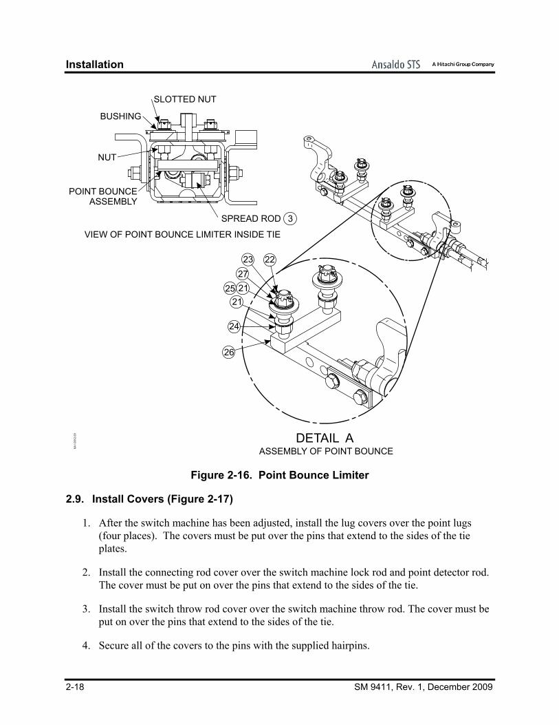
Once the switch machine is secured to the support ties and the connecting rods are all solidly connected, adjust the point bounce limiter (Figure 2-16).
1. Remove the cotter pin (Item 22) from the stud above the nut (Item 23) on the point bounce limiter. Working inside the center of Tie No. 1, loosen the nuts (Item 23 and Item 24) on each side of the two point bounce limiters (Item 26).
2. Adjust the nuts (Item 23) to achieve a 1/4”gap between the bottom of the point bounce limiter and the top of the spreader rod (Item 3). (The bottom nut on the stud may have to be loosened further to achieve the desired spacing.)
3. When the 1/4” is achieved, tighten the nuts (Items 23 and 24) while maintaining the 1/4” gap on both of the limiters and insert the cotter pin in the hole on the point bounce limiter studs.
Installation
2-18 SM 9411, Rev. 1, December 2009
BUSHING
SLOTTED NUT
NUT
POINT BOUNCE ASSEMBLY
SPREAD ROD
VIEW OF POINT BOUNCE LIMITER INSIDE TIE
DETAIL A
26
24
21
2725 21
22
3
23
ASSEMBLY OF POINT BOUNCE6A1.
0012
.00
Figure 2-16. Point Bounce Limiter
2.9. Install Covers (Figure 2-17)
1. After the switch machine has been adjusted, install the lug covers over the point lugs (four places). The covers must be put over the pins that extend to the sides of the tie plates.
2. Install the connecting rod cover over the switch machine lock rod and point detector rod. The cover must be put on over the pins that extend to the sides of the tie.
3. Install the switch throw rod cover over the switch machine throw rod. The cover must be put on over the pins that extend to the sides of the tie.
4. Secure all of the covers to the pins with the supplied hairpins.

Installation
SM 9411, Rev. 1, December 2009 2-19
CONNECTING ROD COVER LUG COVERS
LUG COVERSSWITCH THROW ROD COVER
Figure 2-17. Covers on the RIT Assembly
2.10. Switch Heaters
2.10.1. Calrod Heaters
If Calrod heaters are used, connect the field wires to the heater junction boxes (Figure 2-18) in Tie 1 and Tie 2.
AA
SECTION A-A
SIDE VIEW OF TIE
1.0036.35
REF. 1.00
1.00
3.0070.0038.00
HEATERJUNCTIONBOX
FRONT HEATER BRACKET
CENTER HEATER BRACKET
REAR HEATER BRACKET
NOTE: ALL DIMENSIONS ARE IN INCHES
Figure 2-18. Electrical Connection for Calrod Heater

Installation
2-20 SM 9411, Rev. 1, December 2009
2.10.2. Blower Style Heaters
Blower style heaters are not available at this time.
2.11. Site Restoration
NOTE For optimum operation, It is STRONGLY recommended that the layout be ballasted and fully machined tamped after installation is complete.
Once the RIT assembly is installed and securely connected to the rails, the roadbed can be replaced in the normal manner per the railroad’s standard practice. Extra attention should be directed at tamping the ballast under and around the ties to ensure that they are supported properly.
The area at the switch machine has to be ballasted also to ensure that the support ties are properly supported. This is different than the standard turnout. Be sure the support ties have all been tamped.
CAUTION
Before any ballast is dumped around the rails, make sure the covers are all on the ties to avoid getting any ballast into the ties and hindering movement of the connecting rods.

Maintenance
SM 9411, Rev. 1, December 2009 3-1
3. MAINTENANCE Maintenance should be performed on the associated switch machine in accordance with the railroad’s internal maintenance schedule and the maintenance requirements for the switch machine as presented in the switch machine service manual. This section provides the necessary periodic preventive maintenance procedures that must be performed to ensure continuous, proper, and efficient operation of the RIT layout including periodic inspections.
WARNING To prevent possible personal injury, power must be removed from the switch machine prior to performing any inspection or maintenance in or around the layout.
NOTE As a general guideline for the procedures included in this section of the manual, the Nord-Lock washers used in the RIT Assembly should be torqued to the following recommended torque values:
1/2” bolt 70.2 ft-lb
5/8” bolt 139 ft-lb
3/4” bolt 245 ft-lb
7/8” bolt 394 ft-lb
1” bolt 595 ft-lb
3.1. Preventive Maintenance
The following preventive maintenance procedures are intended to detect possible causes of switch machine failure before an actual failure occurs. Detection of such possible failures is accomplished by a scheduled maintenance process, whereby the switch machine is inspected, cleaned, lubricated, and performance-tested in the field on a periodic basis.
The preventive maintenance procedures should be performed on a regular basis in accordance with the recommended schedule shown in Table 3-1. The actual time interval will depend on the customer’s own operating rules and/or experience.
Maintenance
3-2 SM 9411, Rev. 1, December 2009
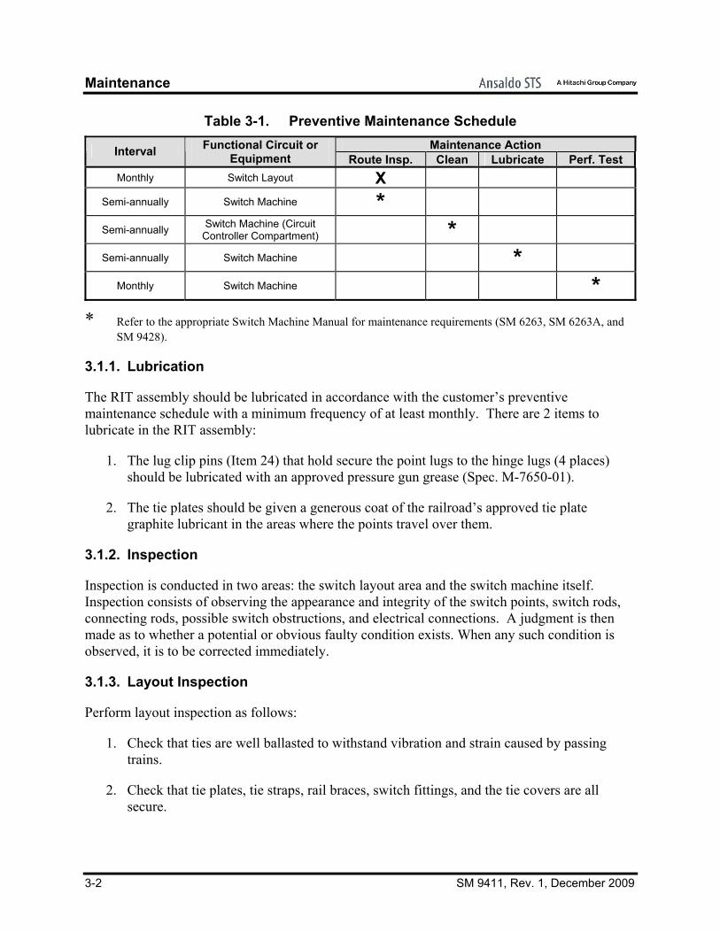
Table 3-1. Preventive Maintenance Schedule Maintenance Action Interval Functional Circuit or
Equipment Route Insp. Clean Lubricate Perf. Test Monthly Switch Layout X
Semi-annually Switch Machine *
Semi-annually Switch Machine (Circuit Controller Compartment) *
Semi-annually Switch Machine *
Monthly Switch Machine * * Refer to the appropriate Switch Machine Manual for maintenance requirements (SM 6263, SM 6263A, and
SM 9428).
3.1.1. Lubrication
The RIT assembly should be lubricated in accordance with the customer’s preventive maintenance schedule with a minimum frequency of at least monthly. There are 2 items to lubricate in the RIT assembly:
1. The lug clip pins (Item 24) that hold secure the point lugs to the hinge lugs (4 places) should be lubricated with an approved pressure gun grease (Spec. M-7650-01).
2. The tie plates should be given a generous coat of the railroad’s approved tie plate graphite lubricant in the areas where the points travel over them.
3.1.2. Inspection
Inspection is conducted in two areas: the switch layout area and the switch machine itself. Inspection consists of observing the appearance and integrity of the switch points, switch rods, connecting rods, possible switch obstructions, and electrical connections. A judgment is then made as to whether a potential or obvious faulty condition exists. When any such condition is observed, it is to be corrected immediately.
3.1.3. Layout Inspection
Perform layout inspection as follows:
1. Check that ties are well ballasted to withstand vibration and strain caused by passing trains.
2. Check that tie plates, tie straps, rail braces, switch fittings, and the tie covers are all secure.

Maintenance
SM 9411, Rev. 1, December 2009 3-3
3. Check that there are no signs of water accumulation around switch machine or inside the ties (proper drainage exists).
4. Remove any material within the layout that could obstruct switch movement.
5. Remove any material within the tie that could obstruct movement of the connecting rods.
3.1.4. Switch Machine Inspection
Perform switch machine inspection in accordance with the appropriate switch machine manual (SM 6263, SM 6263A, and SM 9428) to ensure the proper operation of the switch machine. The performance test should be done in accordance with customer’s operating rules. The test should include mechanical operation of the switch mainline, and electrical tests of power distribution and switch control and indication circuits. Erratic or faulty operation and/or indications should be promptly referred to the proper authority for corrective action.
It is recommended that the RIT inspection be performed at the same time.
3.2. Periodic Maintenance
3.2.1. Cleaning
Perform switch machine inspection in accordance with the appropriate switch machine manual to ensure the proper operation of the switch machine.
3.2.2. Adjustment
Adjustments should be made to the connecting rods inside the ties in accordance with Table 3-1.
3.2.3. Lubrication
Lubrication should be made to the connecting rods inside the ties in accordance with Table 3-1.
3.2.4. Performance Testing
Performance testing of the RIT layout should be done in accordance with Table 3-1.

Maintenance
3-4 SM 9411, Rev. 1, December 2009

Parts List
SM 9411, Rev. 1, December 2009 4-1
4. PARTS LIST
4.1. RIT Assembly N4928XXXX
(Table 4-1 and Figure 4-1)
Table 4-1. Parts List for RIT Assembly Item Description Part No.
1 Single Tie Weldment N49260401 2 Machine Mounting Hardware – 3/4” dia. (includes
items 101 through 108) X49200006
3 Point Lugs with 1” Hardware X49200010 4 Lug, Lock Rod Casting Q49201801 5 Point Detector Lug Casting Q49202001 6 Lug Cover Assembly N492315041 7 Hairpin J486009-0009 8 Operating Rod Nut M49232201 9 Washer, Flat, 7/8”, 1-3/4” OD J4751200179
10 Washer, 7/8” steel, Lock J047773 11 Bolt, 7/8” – 9 x 3-1/4”, Hex. M193131 12 Cotter Pin, 3/16” x 2” Spring Steel J048636 13 Nut, Jam, 1-1/4” – 7, UNC 2B J048044 14 Nut, Cast, M.I. M208570 15 Nut, Jam, 1” – 8, UNC 2B J048033 16 Point / Lock Lug Washer M49204901 17 Nut, 1-1/4” – 7 Steel Hex Head J048176 18 Nut, 1” – 8 UNC, 2B Heavy J048030 19 Connecting Rod Cover R49205201 20 Switch Throw Rod Cover R49205301 21 Tie Strap M281723009 22 Washer, 3/4” Flat J047506 23 Bolt, Lag, 3/4” X 6 J050347 24 Washer, Lock, 3/4” Steel J047772 25 Bolt, Hex Head, 3/4”-10 x 2-3/4” J5001240223 26 Angle Tie Strap M49207001 27 Bolt, 1” – 8 x 3-1/2” Hex J5001240240 28 Washer, Flat 1-1/16” ID, 2” OD J4751200180 29 Nut, Lock, Nylon 1” – 8 Hex J0481620017 30 Non-Spring Basket Nut M49205701 31 Non-Spring Basket Adj R49205603 32 Basket M49204702
101 Bushing, 3/4” Casting Q49207504 102 Screw, 3/4-10 x 5”, Hex J5000820180 103 Washer, 3/4” Plate J047506 104 Washer, Lock, 3/4” Steel J047772 105 Nut, 3/4” - 10, Hex, Steel J048026 106 Bolt, 7/8” - 9 x 5” Hex J5001260271 107 Washer, Lock, 7/8” Steel J047773 108 Nut, 7/8” - 9, Hex, Steel J048029

Parts List
4-2 SM 9411, Rev. 1, December 2009
A A
BB
C C
SECTION A-A
SECTION B-B
SECTION C-C
SECTION D-D
D
D
3031
2
3
32
6
45
19
20
1
1
2729 28
7
21
23
22 24 25
23
2633
14 15
1815
1317
16
13
13 17 16
11 10 9 8 12
2
106
107
108
101102103104105
7
22.00
22.00
22.00
54
8.00
10.00
10.00
161.00
NOTE: ALL DIMENSIONS ARE
IN INCHES
Figure 4-1. Rod-in-Tie Typical Layout

Parts List
SM 9411, Rev. 1, December 2009 4-3
4.2. RIT Tie Assemblies
(Table 4-2 and Figure 4-2)
Table 4-2. Parts List for the Tie Assemblies Item Description Part No.
1 Tie No. 1 Assembly N49260001 2 Tie No. 2 Assembly N49260002 3 Tie Plate Insulation M49230801 4 Tie Plate with Pins Layout Specific 5 Tie Plate with Pins Layout Specific 6 Tie Plate with Pins Layout Specific 7 Gage Insulator J7002160025 8 Tie Plate Insulated Bushing J7002160024 9 Powerbolt, 1” Dia. J5001240256
10 Washer, 3/4” Flat J047506 11 Washer, 3/4” Lock J047772 12 Nut, 3/4” – 10 UNC 2B Heavy J048091 13 Cotter Pin, 3/16” x 2, Spring Steel J048636 14 Washer, Flat, 2-1/2” OD. J4751200188 15 Powerbolt Collar, 1” ID Flange J5001240257 16 Tie End Cover R49202901 17 Washer, Flat, 7/8”, 1-3/4” OD J4751200179 18 Washer, Lock, .894 ID, 1.3459 OD J4751210144 19 Bolt, Hex 7/8” – 9 x 2-1/4” J5001240216 20 Nut, 1-8 UNC 2b Heavy J048030 21 Fixture, Flat, Installation M49211301 22 Washer,1 Steel Plate J047509 23 Bolt-1"-8 x 8 Hx Hd, Sst J4650190164 24 RIT Fixture, Bottom M49206201 25 Washer,1p S L M1060 75 J047774 26 Bolt, 7/8"-9 X 3-1/4"L, Hex Hd J5001240275

Parts List
4-4 SM 9411, Rev. 1, December 2009
2
1345
6
7
DETAIL B
915
14
8
19 18
19
17
16
16
DETAIL A
SEE DETAIL ASEE DETAIL B
7
10
11
12
13
FIELD INSTALLATION
FIELD INSTALLATION
2421
23
26 1718
19
17
18
1817
20252222
6A1.
0013
.00
Figure 4-2. Tie Assemblies

Parts List
SM 9411, Rev. 1, December 2009 4-5
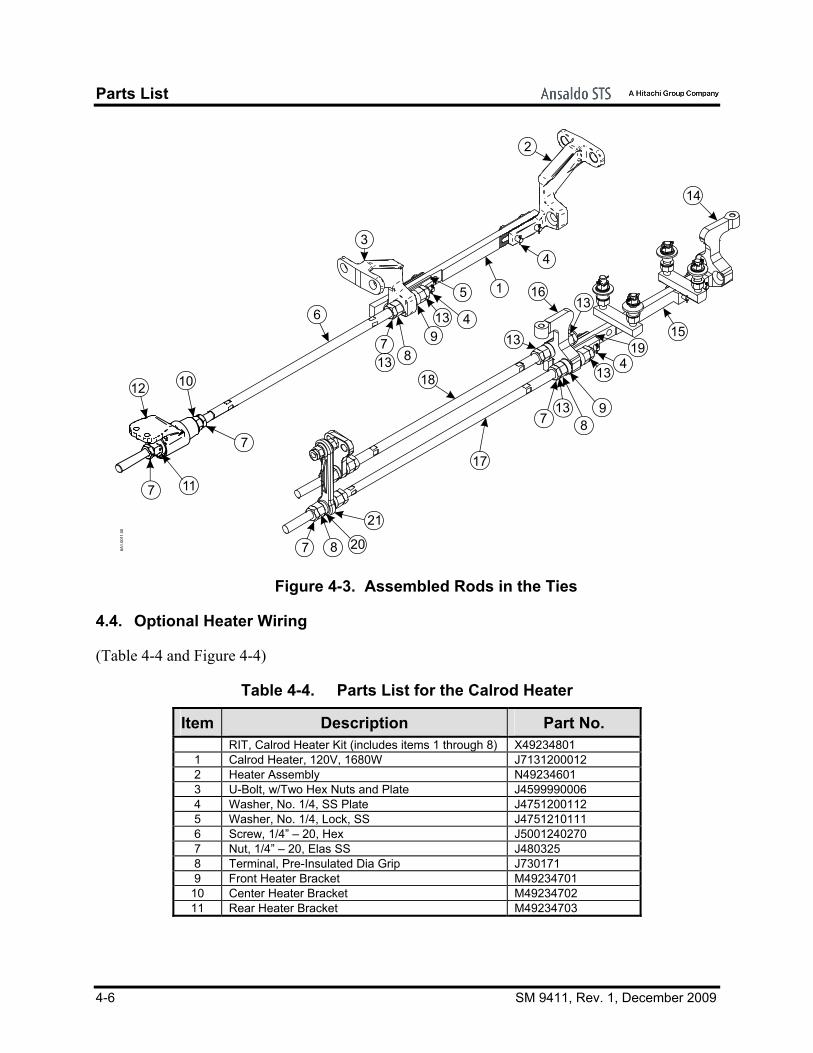
4.3. Connecting Rods in the Ties
(Table 4-3 and Figure 4-3)
Table 4-3. Parts List for the Connecting Rods Item Description Part No.
1 Spreadrod, Center M49203901 2 Switch Throw Lug, RH M49237302 3 Switch Throw Lug, LH M49238102 4 Cotter Pin, 1/8” x 1-1/4” Steel J048622 5 Spreadrod Insulation M49203401 6 Switch Throw Rod M49204002 7 Nut, 1-1/4” - 7 UNC 2B Jam J048044 8 Nut, 1-1/4” Hex Head Steel J048176 9 Stop Washer Q49202501
10 RIT, Non-Spring Basket Nut M49205701 11 RIT Non-Spring Basket Adj R49205603 12 RIT Basket M49204702 13 Washer,Nordlock,1-1/4"Bolt Size, Zfc, Rohs JR112870020000 14 Point/Lock Hinge Lug (RH) M49202302 15 Center Spreadrod M49203901 16 Point/Locking Hinge Lug, LH M49202402 17 Point Detector Connecting Rod M49201902 18 Lock Rod Connecting Rod M49205101 19 Spreadrod Insulation M49203401 20 Point/Lock Lug Washer M49204901 21 Point Detector Lug Casting Q49202001
Parts List
4-6 SM 9411, Rev. 1, December 2009
6A1.
0011
.00
18
17
16
7 8913
13
13
13
4
14
1519
21
2087
3
7813
13 4
5
6
12 10
7
117
1
2
4
9
Figure 4-3. Assembled Rods in the Ties
4.4. Optional Heater Wiring
(Table 4-4 and Figure 4-4)
Table 4-4. Parts List for the Calrod Heater
Item Description Part No. RIT, Calrod Heater Kit (includes items 1 through 8) X49234801 1 Calrod Heater, 120V, 1680W J7131200012 2 Heater Assembly N49234601 3 U-Bolt, w/Two Hex Nuts and Plate J4599990006 4 Washer, No. 1/4, SS Plate J4751200112 5 Washer, No. 1/4, Lock, SS J4751210111 6 Screw, 1/4” – 20, Hex J5001240270 7 Nut, 1/4” – 20, Elas SS J480325 8 Terminal, Pre-Insulated Dia Grip J730171 9 Front Heater Bracket M49234701
10 Center Heater Bracket M49234702 11 Rear Heater Bracket M49234703

Parts List
SM 9411, Rev. 1, December 2009 4-7
AA
SECTION A-A
BBSECTION B-B
108”
1
1110
1
4
3
5
9
DETAIL A
"DETAIL A"
U-BOLT
NUT
PLATE
LOCK WASHERWASHER
HEATER
6A1.
0009
.00 "DETAIL D"
2
6
7
8
SEE DETAIL D
Figure 4-4. Calrod Heater Wiring in Tie

Parts List
4-8 SM 9411, Rev. 1, December 2009

Technical Support
SM 9411, Rev. 1, December 2009 5-1
5. TECHNICAL SUPPORT
The Rapid Action Information Link Team (RAIL Team) is a group of experienced product and application engineers ready to assist you to resolve any technical issues concerning this product. Contact the RAIL Team in the United States at 1-800-652-7276 or by e-mail at [email protected].

Technical Support
5-2 SM 9411, Rev. 1, December 2009
End of Manual