rol johnson 6/22/2005 nufact05 plenary 1 technical challenges of muon colliders rolland p. johnson...
TRANSCRIPT

Rol Johnson 6/22/2005Rol Johnson 6/22/2005 NuFact05 PlenaryNuFact05 Plenary 11
Technical Challenges Technical Challenges of Muon Collidersof Muon Colliders
Rolland P. Johnson Rolland P. Johnson
Muon Colliders need small muon flux to reduce proton Muon Colliders need small muon flux to reduce proton driver demands, detector backgrounds, and site boundary driver demands, detector backgrounds, and site boundary radiation levels. Extreme beam cooling is therefore radiation levels. Extreme beam cooling is therefore required to produce high luminosity at the beam-beam required to produce high luminosity at the beam-beam tune shift limit and to allow the use of high frequency RF tune shift limit and to allow the use of high frequency RF for acceleration to very high energy in recirculating Linacs. for acceleration to very high energy in recirculating Linacs.
I will briefly describe 7 new ideas that are driven by these I will briefly describe 7 new ideas that are driven by these requirements, where some of the ideas may be useful for requirements, where some of the ideas may be useful for Neutrino FactoriesNeutrino Factories
Muons, Inc.

Rol Johnson 6/22/2005Rol Johnson 6/22/2005 NuFact05 PlenaryNuFact05 Plenary 22
Muons, Inc. SBIR/STTR Collaboration:Muons, Inc. SBIR/STTR Collaboration:(Small Business Innovation Research grants)(Small Business Innovation Research grants)
Fermilab; Fermilab; • Victor Yarba, Chuck Ankenbrandt, Emanuela Barzi, Victor Yarba, Chuck Ankenbrandt, Emanuela Barzi,
Licia del FrateLicia del Frate, Ivan Gonin, Timer Khabiboulline, Al , Ivan Gonin, Timer Khabiboulline, Al Moretti, Dave Neuffer*, Milorad Popovic*, Gennady Moretti, Dave Neuffer*, Milorad Popovic*, Gennady Romanov, Daniele TurrioniRomanov, Daniele Turrioni
IIT; IIT; • Dan Kaplan*, Dan Kaplan*, Katsuya YoneharaKatsuya Yonehara
JLab; JLab; • Slava Derbenev, Alex Bogacz*, Slava Derbenev, Alex Bogacz*, Kevin BeardKevin Beard, Yu-Chiu , Yu-Chiu
ChaoChao Muons, Inc.; Muons, Inc.;
• Rolland Johnson*,Rolland Johnson*, Mohammad Alsharo’a Mohammad Alsharo’a, , Pierrick Pierrick HanletHanlet, Bob Hartline, Moyses Kuchnir, , Bob Hartline, Moyses Kuchnir, Kevin Paul*Kevin Paul*, Tom , Tom RobertsRoberts
UnderlinedUnderlined are 6 accelerator physicists in training, supported by SBIR/STTR grants are 6 accelerator physicists in training, supported by SBIR/STTR grants * present at this workshop* present at this workshop

Rol Johnson 6/22/2005Rol Johnson 6/22/2005 NuFact05 PlenaryNuFact05 Plenary 33
5 TeV
Modified Livingston Plot taken from: W. K. H. Panofsky and M. Breidenbach, Rev. Mod. Phys. 71, s121-s132 (1999)
The Goal: Back to the Livingston Plot

4NuFact05 PlenaryRol Johnson 6/22/2005
2.5 km Linear Collider Segment
2.5 km Linear Collider Segment
postcoolers/preaccelerators
5 TeV Collider 1 km radius, <L>~5E34
10 arcs separated vertically in one tunnel
HCC
300kW proton driver
Tgt
IR IR
5 TeV ~ SSC energy reach
~5 X 2.5 km footprint
Affordable LC length, includes ILC people, ideas
High L from small emittance!
1/10 fewer muons than originally imagined: a) easier p driver, targetry b) less detector background c) less site boundary radiation
Rol Johnson 6/22/2005 NuFact05 Plenary 5
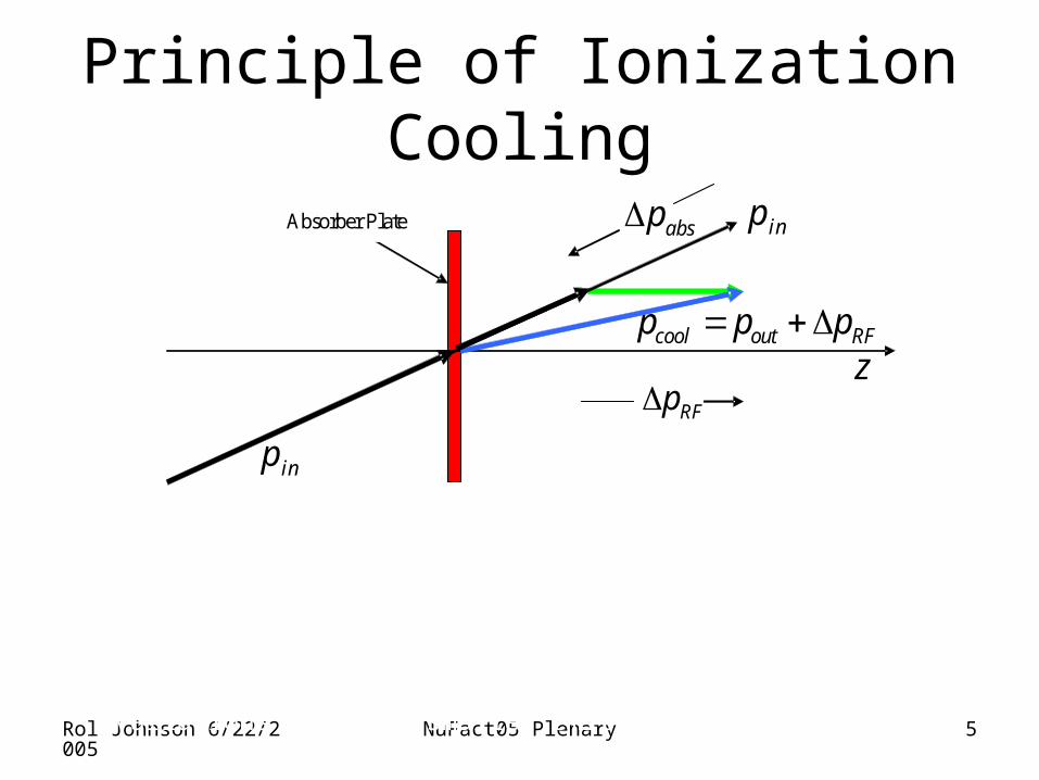
Principle of Ionization Cooling
z
RFp
inp
cool out RFp p p
absp
inp
a
Absorber Plate
Each particle loses momentum by ionizing a low-Z absorber
Only the longitudinal momentum is restored by RF cavities
The angular divergence is reduced until limited by multiple scattering
Successive applications of this principle with clever variations leads to smaller emittances for high Luminosity with fewer muons

Rol Johnson 6/22/2005
NuFact05 Plenary 6
Muon Collider Emittances and Luminosities
• After:
– Precooling
– Basic HCC 6D
– Parametric-resonance IC
– Reverse Emittance Exchange
εN tr εN long.
20,000 µm 10,000 µm
200 µm 100 µm
25 µm 100 µm
2 µm 2 cm
3z mm 4/ 3 10
At 2.5 TeV
35 210*
10 /peak
N nL f cm s
r
42.5 10
0 50f kHz
0.06 * 0.5cm
20 Hz Operation:
10n
111 10N
9 13 19(26 10 )(6.6 10 )(1.6 10 ) 0.3Power MW
34 24.3 10 /L cm s 0.3 / p
50 2500 /ms turns

Rol Johnson 6/22/2005
NuFact05 Plenary 7
Idea #1: RF Cavities with Pressurized H2
•Dense GH2 suppresses high-voltage breakdown –Small MFP inhibits avalanches (Paschen’s Law)
•Gas acts as an energy absorber–Needed for ionization cooling
•Only works for muons–No strong interaction scattering like protons–More massive than electrons so no showers
R. P. Johnson et al. invited talk at LINAC2004, http://www.muonsinc.com/TU203.pdf Pierrick M. Hanlet et al., Studies of RF Breakdown of Metals in Dense Gases, PAC05Kevin Paul et al., Simultaneous bunching and precooling muon beams with gas-filled RF cavities, PAC05 Mohammad Alsharo'a et al., Beryllium RF Windows for Gaseous Cavities for Muon Acceleration, PAC05Also see WG3 talks by D. Cline, S. Kahn, and A. Klier on ring coolers for other use of ideas 1 and 2

Rol Johnson 6/22/2005
NuFact05 Plenary 8
Lab G Results, Molybdenum Electrode
H2 vs He RF breakdown at 77K, 800MHz
0
10
20
30
40
50
60
70
80
0 100 200 300 400 500 600
Pressure (PSIA)
Max
Sta
ble
Gra
die
nt
(MV
/m)
Linear Paschen Gas Linear Paschen Gas Breakdown RegionBreakdown Region
Metallic Surface Metallic Surface Breakdown RegionBreakdown Region
Waveguide BreakdownWaveguide Breakdown
Hydrogen Hydrogen
HeliumHelium
Fast conditioning: 3 h from 70 to 80 Fast conditioning: 3 h from 70 to 80 MV/mMV/m
Rol Johnson 6/22/2005
NuFact05 Plenary 9
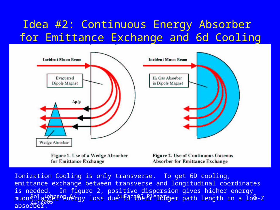
Idea #2: Continuous Energy Absorber for Emittance Exchange and 6d Cooling
Ionization Cooling is only transverse. To get 6D cooling, emittance exchange between transverse and longitudinal coordinates is needed. In figure 2, positive dispersion gives higher energy muons larger energy loss due to their longer path length in a low-Z absorber.

Rol Johnson 6/22/2005
NuFact05 Plenary 10
Idea #3: six dimensional Cooling with HCC and continuous absorber
• Helical cooling channel (HCC) – Solenoidal plus transverse helical dipole and
quadrupole fields– Helical dipoles known from Siberian Snakes– z-independent Hamiltonian
Derbenev & Johnson, Theory of HCC, April/05 PRST-AB

Rol Johnson 6/22/2005
NuFact05 Plenary 11
Photograph of a helical coil for the AGS Snake11” diameter helical dipole: we want ~2.5 x larger bore

Rol Johnson 6/22/2005 NuFact05 Plenary 12
2 / 1k m
100 /p MeV c.7 , 3.5b T B T
15B br cm
30coilr cm
Due to b
Due to B
Motion due to b + B
Magnet coils
cosb z kz
;
;
h dipole z
solenoid z z
F p B b B
F p B B B
/ 1.zp p
Helical Cooling Channel. Derbenev invention of combination of Solenoidal and helical dipole fields for muon cooling with emittance exchange and large acceptance. Well-suited to continuous absorber.
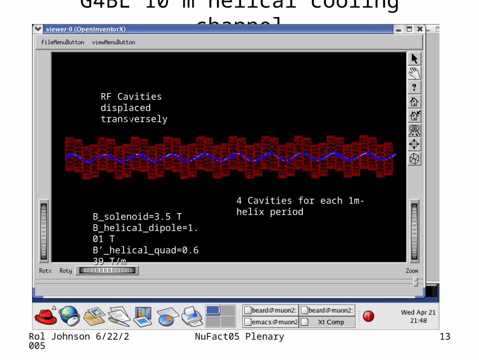
Rol Johnson 6/22/2005 NuFact05 Plenary 13
G4BL 10 m helical cooling channel
RF Cavities displaced RF Cavities displaced transversely transversely
4 Cavities for each 1m-helix period4 Cavities for each 1m-helix period
B_B_solenoid=3.5 T =3.5 T B_helical_dipole=1.01 T =1.01 T B’_helical_quad=0.639 T/mB’_helical_quad=0.639 T/m

Rol Johnson 6/22/2005 NuFact05 Plenary 14
G4BL End view of 200MeV HCC
Radially offset RF cavitiesRadially offset RF cavities
Beam particles (blue) oscillating Beam particles (blue) oscillating about the periodic orbit (white)about the periodic orbit (white)

Rol Johnson 6/22/2005
NuFact05 Plenary 15
HCC simulations w/ GEANT4 (red) and ICOOL (blue)
6D Cooling factor ~5000
Katsuya Yonehara, et al., Simulations of a Gas-Filled Helical Cooling Channel, PAC05

Rol Johnson 6/22/2005
NuFact05 Plenary 16
Idea #4: HCC with Z-dependent fields
40 m evacuated helical magnet pion decay channel followed by a 5 m liquid hydrogen HCC (no RF)
Rol Johnson 6/22/2005
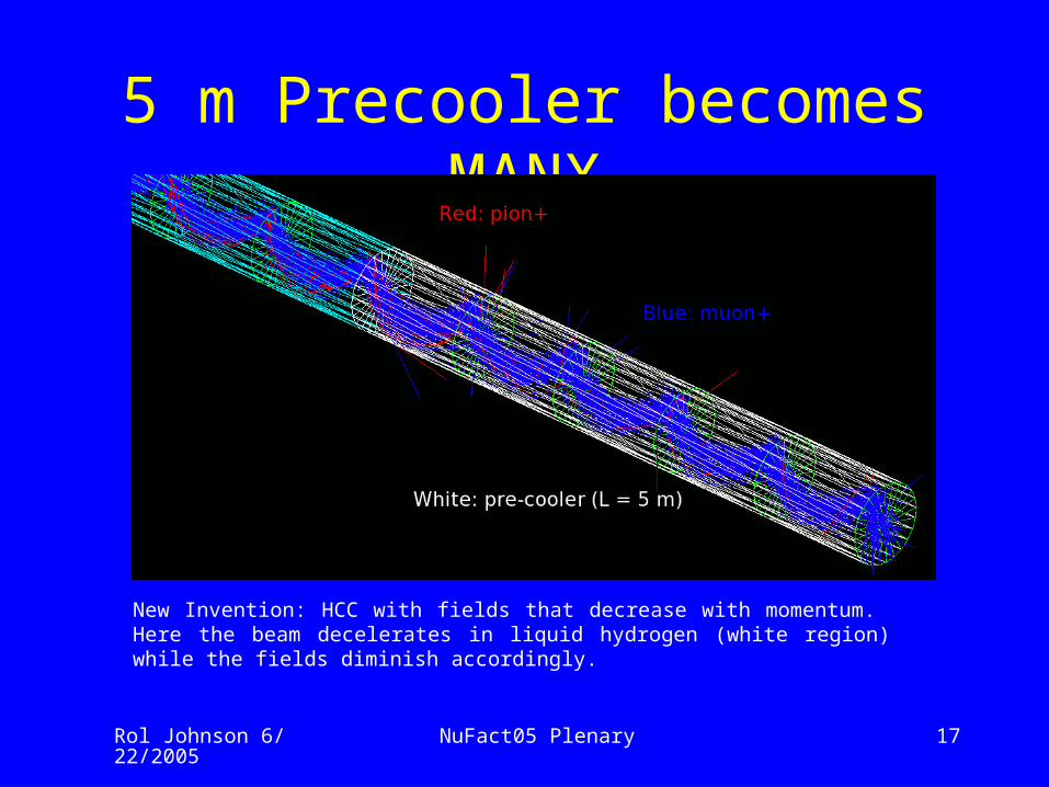
NuFact05 Plenary 17
5 m Precooler becomes MANX
New Invention: HCC with fields that decrease with momentum. Here the beam decelerates in liquid hydrogen (white region) while the fields diminish accordingly.
Rol Johnson 6/22/2005
NuFact05 Plenary 18
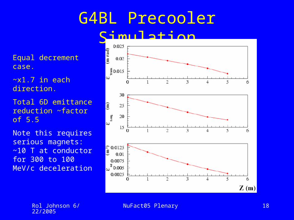
G4BL Precooler Simulation
Equal decrement case.
~x1.7 in each direction.
Total 6D emittance reduction ~factor of 5.5
Note this requires serious magnets: ~10 T at conductor for 300 to 100 MeV/c deceleration

Rol Johnson 6/22/2005
NuFact05 Plenary 19
Idea #5: MANX 6-d demonstration experimentMuon Collider And Neutrino Factory eXperiment
• To Demonstrate
– Longitudinal cooling
– 6D cooling in cont. absorber
– Prototype precooler
– New technology • HCC
• HTS
Thomas J. Roberts et al., A Muon Cooling Demonstration Experiment, PAC05

Rol Johnson 6/22/2005
NuFact05 Plenary 20
G4BL MANX with MICE spectrometers

Rol Johnson 6/22/2005
NuFact05 Plenary 21
Muon Trajectories in 3-m MANX
Rol Johnson 6/22/2005
NuFact05 Plenary 22
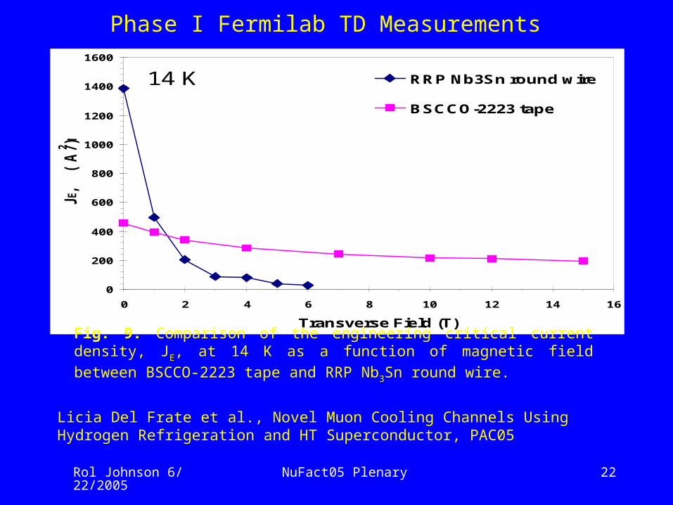
Phase I Fermilab TD Measurements
0
200
400
600
800
1000
1200
1400
1600
0 2 4 6 8 10 12 14 16
Transverse Field (T)
JE, (
A/m
m2 )RRP Nb3Sn round wire
BSCCO-2223 tape
14 K
Fig. 9. Comparison of the engineering critical current density, JE, at 14 K as a function
of magnetic field between BSCCO-2223 tape and RRP Nb3Sn round wire.
Licia Del Frate et al., Novel Muon Cooling Channels Using Hydrogen Refrigeration and HT Superconductor, PAC05

Rol Johnson 6/22/2005
NuFact05 Plenary 23
MANX/Precooler H2 or He Cryostat
Figure XI.2. Latest iteration of 5 m MANX cryostat schematic.
Rol Johnson 6/22/2005
NuFact05 Plenary 24
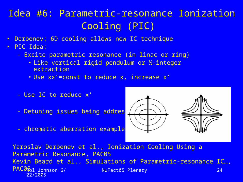
Idea #6: Parametric-resonance Ionization Cooling (PIC)
• Derbenev: 6D cooling allows new IC technique• PIC Idea:
– Excite parametric resonance (in linac or ring)• Like vertical rigid pendulum or ½-integer extraction• Use xx’=const to reduce x, increase x’
– Use IC to reduce x’
– Detuning issues being addressed
– chromatic aberration example
Yaroslav Derbenev et al., Ionization Cooling Using a Parametric Resonance, PAC05Kevin Beard et al., Simulations of Parametric-resonance IC…, PAC05
x

Rol Johnson 6/22/2005 NuFact05 Plenary 25
Transverse PIC schematic
/8
Absorber plates Parametric resonance lenses
Conceptual diagram of a beam cooling channel in which hyperbolic trajectories are generated in transverse phase space by perturbing the beam at the betatron frequency, a parameter of the beam oscillatory behavior. Neither the focusing magnets that generate the betatron oscillations nor the RF cavities that replace the energy lost in the absorbers are shown in the diagram.
The longitudinal scheme is more complex.

Rol Johnson 6/22/2005
NuFact05 Plenary 26
7.20
Fri Apr 08 12:45:48 2005 OptiM - MAIN: - D:\6Dcooling\Sol chann - summ\sol_cav_cell.opt
20
0
50
BE
TA
_X
&Y
[m]
DIS
P_
X&
Y[m
]
BETA_X BETA_Y DISP_X DISP_Y
7.20
Fri Apr 08 12:46:30 2005 OptiM - MAIN: - D:\6Dcooling\Sol chann - summ\sol_cav_cell.opt
0.5
0P
HA
SE
_X
&Y
Q_X Q_Y
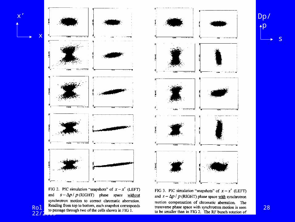
Beta functions and phases for the solenoid triplet cell. Thin absorbers are placed at the two central focal points. In the simulations for FIG 2 the lost energy is simply replaced at the absorbers. For FIG 3, 400 MHz RF cavities shown as blue bars replace the lost energy and provide synchrotron motion. SEE BOGACZ TALK!

Rol Johnson 6/22/2005
NuFact05 Plenary 27
Openinventor display from the G4Beamline simulation program showing the cell being modeled. The orange cylinders are solenoids as described above and the green cylinder is a solenoid of opposite polarity. The red cylinders represent 400 MHz RF cavities, the cyan disks are the energy absorbers, the large gray disks represent virtual detectors, and the green and red lines at the left end are the horizontal and vertical axes.
The same G4Beamline view as above but with transparent beam line elements so that the muon trajectories can be seen. Detuning compensation schemes are being developed.
Rol Johnson 6/22/2005
NuFact05 Plenary 28
x
x’ Dp/p
s

Rol Johnson 6/22/2005
NuFact05 Plenary 29
Idea #7: Reverse Emittance Exchange
• At 2.5 TeV/c, Δp/p reduced by >1000.• Bunch is then much shorter than needed to
match IP beta function• Use wedge absorber to reduce transverse
beam dimensions (increasing Luminosity) while increasing Δp/p until bunch length matches IP
• Subject of new STTR grant

30NuFact05 PlenaryRol Johnson 6/22/2005
Incident Muon Beam
EvacuatedDipole
Wedge Abs
EvacuatedDipole
Wedge Abs
Incident Muon Beam
Figure 1. Conceptual diagram of the usual mechanism for reducing the energy spread in a muon beam by emittance exchange. An incident beam with small transverse emittance but large momentum spread (indicated by black arrows) enters a dipole magnetic field. The dispersion of the beam generated by the dipole magnet creates a momentum-position correlation at a wedge-shaped absorber. Higher momentum particles pass through the thicker part of the wedge and suffer greater ionization energy loss. Thus the beam becomes more monoenergetic. The transverse emittance has increased while the longitudinal emittance has diminished.
Figure 2. Conceptual diagram of the new mechanism for reducing the transverse emittance of a muon beam by reverse emittance exchange. An incident beam with large transverse emittance but small momentum spread passes through a wedge absorber creating a momentum-position correlation at the entrance to a dipole field. The trajectories of the particles through the field can then be brought to a parallel focus at the exit of the magnet. Thus the transverse emittance has decreased while the longitudinal emittance has increased.
Figure 1. Emittance ExchangeFigure 1. Emittance Exchange Figure 2. Reverse Emittance ExchangeFigure 2. Reverse Emittance Exchange
Rol Johnson 6/22/2005
NuFact05 Plenary 31
Seven New Ideas for Bright Beams for High Luminosity Muon Colliders
supported by SBIR/STTR grants
H2-Pressurized RF Cavities
Continuous Absorber for Emittance Exchange
Helical Cooling Channel
Z-dependent HCC
MANX 6d Cooling Demo
Parametric-resonance Ionization Cooling
Reverse Emittance ExchangeIf we succeed to develop these ideas, an Energy Frontier Muon Collider will become a compelling option for High Energy Physics! (The first five ideas can be used in Neutrino Factory designs.)

Rol Johnson 6/22/2005
NuFact05 Plenary 32
Challenges for Muon Colliders
• Extreme 6D muon cooling essential– Need simulations and demos, more ideas
• Acceleration – Can use ILC technology with recirculation– A good case for collaboration (10xECOM at half the cost?)– Mitigation of decay electrons
• Storage Ring/detectors– Low beta designs, exploit symmetry for multiple IPs– Integrate detectors with IP designs, solve e backgrounds– Understand neutrino-induced site boundary radiation