role of refractive index in metalens performance
TRANSCRIPT
Role of refractive index in metalens performanceELYAS BAYATI,1,* ALAN ZHAN,2 SHANE COLBURN,1 MAKSYM VIKTOROVICH ZHELYEZNYAKOV,1
AND ARKA MAJUMDAR1,2
1Department of Electrical and Computer Engineering, University of Washington, Seattle, Washington 98195, USA2Department of Physics, University of Washington, Seattle, Washington 98195, USA*Corresponding author: [email protected]
Received 7 November 2018; revised 22 January 2019; accepted 22 January 2019; posted 24 January 2019 (Doc. ID 351300);published 14 February 2019
Sub-wavelength diffractive optics, commonly known as metasurfaces, have recently garnered significant attentionfor their ability to create ultra-thin flat lenses with a high numerical aperture. Several materials with differentrefractive indices have been used to create metasurface lenses (metalenses). In this paper, we analyze the role ofrefractive index on the performance of these metalenses. We employ both forward and inverse design method-ologies to perform our analysis. We found that, while high-refractive-index materials allow for extreme reductionof the focal length, for moderate focal lengths and numerical aperture (<0.6), there is no appreciable difference inthe focal spot size and focusing efficiency for metalenses made of different materials with refractive indices rangingbetween 1.2 and 3.43 in forward design, and 1.25 and 3.5 in inverse design. © 2019 Optical Society of America
https://doi.org/10.1364/AO.58.001460
1. INTRODUCTION
Dielectric metasurfaces, two-dimensional quasi-periodic arraysof subwavelength scatterers, have recently emerged as a prom-ising technology to create ultra-thin, flat, and miniature opticalelements [1]. With these sub-wavelength scatterers, metasurfa-ces shape optical wavefronts, modifying the phase, amplitude,and/or polarization of incident light in transmission or reflec-tion. Many different optical components such as lenses [2,3],focusing mirrors [4], vortex beam generators [5,6], holographicmasks [7,8], polarization optics [9,10], and freeform surfaces[11] have been demonstrated using metasurfaces. While thesub-wavelength structuring provides the necessary phase-shiftfor light manipulation, the material degrees of freedom alsoplay an important role in determining the performance.
Metasurfaces initially relied on deep-subwavelength metallicstructures and operated at mid-infrared frequencies [1]. Thelarge absorption loss in metals made it difficult to create high-efficiency metasurface devices in the visible and near-infrared(NIR) wavelengths. This motivated the fabrication of metasur-faces using dielectric materials because of the low optical loss ofdielectrics at visible and NIR wavelengths. While initial re-search focused on higher-index amorphous silicon (Si) [3,4] atNIR wavelengths, recently, materials with a lower refractive in-dex, such as titanium oxide (TiO2) [12], gallium nitride (GaN)[13], and silicon nitride (SiN) [14,15] have been used to createmetasurfaces operating at visible wavelengths. Based on the em-pirical Moss relation n4 ∼ 1∕Eg [16] with refractive index nand the electronic bandgap Eg , we expect that a large opticaltransparency window necessitates the material refractive index
to be lower. Hence, to create metasurfaces at shorter wave-lengths, we have to rely on materials with a lower refractiveindex. In decreasing the refractive index, however, it is unclearwhat effect there will be on the device performance. Recently,the efficiency of a periodic meta-grating was analyzed at opticalfrequency as a function of the material refractive index [17].The authors reported that for large deflection angles, the effi-ciency decreases with a lower refractive index, but for low de-flection angles, there is no significant difference in the efficiencyof transmissive thick meta-gratings made of different materials.While this analysis with periodic structures can help to quali-tatively understand the performance of a metasurface lens(metalens) with quasi-periodic arrangements of scatterers [18–20],a systematic and quantitative evaluation of material selectionfor metalenses is currently lacking. It is unclear what is the min-imum required dielectric contrast to achieve high-efficiencyand high-numerical-aperture metalenses. Answering this ques-tion is vital for understanding the capabilities, limitations,efficiency, and manufacturability of metalenses over a specificwavelength range. We note that the effect of refractive index isexplicit in the lens maker’s formula [21] for a refractive lens:
1
f� �n − 1�
�1
R−1
R 0
�,
where f is the focal length, n is the refractive index of the lens,and R and R 0 are the radii of curvature of the two sphericalsurfaces of the lens. The angle of refraction, and therefore thefocal length, depends on the curvature of the lens surface andthe material used to construct the lens. However, for metalenses,
1460 Vol. 58, No. 6 / 20 February 2019 / Applied Optics Research Article
1559-128X/19/061460-07 Journal © 2019 Optical Society of America

to the best of our knowledge, there is no study or theoreticalformula relating the refractive index to the focal length ornumerical aperture and the efficiency.
In this paper, we design and analyze metalenses made of ma-terials with a wide range of refractive indices to estimate therelationship between the refractive index and the performanceof metalenses. We analyze metalenses operating in the NIRspectral regime (λ � 1550 nm) in terms of efficiency and fullwidth at half maximum (FWHM). We consider six differentdielectric materials: Si (n � 3.43) [3], TiO2 (n � 2.4) [12],GaN (n � 2.3) [13], SiN (n � 2.0) [14,15], SiO2 (n � 1.5)[22], and an artificial material with a refractive index of 1.2.The index range <2 is of particular importance as large-scaleprintable photonics technology, which is promising for low-costmanufacturing of metasurfaces, requires the refractive index tobe near 1.5 [23]. First, we used a forward design techniquebased on the rigorous coupled-wave analysis (RCWA) [24,25],followed by finite-difference time-domain (FDTD) simulations[3,14]. We compared the focusing efficiency and FWHM atthe focal plane as a function of the numerical aperture for differ-ent materials. We then employed an inverse electromagneticdesign based on the generalized Mie scattering theory andadjoint optimization [26] to calculate the dependence of themetalens performance and FWHM at the focal plane on therefractive indices between 1.25 and 3.5.
2. FORWARD DESIGN METHOD
The main building block of a metalens is a scatterer arrangedin a subwavelength periodic lattice (with a period p). Here, weassume the scatterers to be cylindrical pillars, arranged in a squarelattice, as shown in Fig. 1. Since we have a sub-wavelength
periodicity in a metalens, only the zeroth-order plane wavepropagates a significant distance from the metasurface, andother higher-order diffracted plane waves are evanescent [27].This makes metalenses more efficient compared to other dif-fractive optics.
Forward design of a metalens involves selecting the appro-priate spatial phase profile for the specific optical component,arranging the scatterers on a subwavelength lattice, and spatiallyvarying their dimensions. To have an arbitrary transmissionphase profile, phase shifts of the scatterer should span the0-to-2π range, while maintaining large transmission amplitudes.In our simulation, we used the phase profile of metalens as
ϕ�x, y� � 2π
λ
� ffiffiffiffiffiffiffiffiffiffiffiffiffiffiffiffiffiffiffiffiffiffiffiffiffiffix2 � y2 � f 2
q− f
�:
We discretize this continuous spatial phase profile onto a squarelattice with periodicity p, giving us a discrete spatial phase mapwith different phase values. We then quantize the phase profilewith 10 linear steps between 0 and 2π, corresponding to 10different pillar radii. For each value of this new discrete spatialphase profile, we find the radius of the pillar that most closelyreproduces that phase and place it on the lattice.
The complex transmission coefficient of a zeroth-orderplane wave depends on the lattice periodicity p, scatterer dimen-sions (both the diameter d and thickness t), and refractive indexn. Using RCWA, we calculate the transmission phase and am-plitude of the scatterers as a function of duty cycle (d∕p) fordifferent materials assuming a periodic boundary condition(Fig. 2). For different refractive indices, we can find several setsof thickness t and lattice periodicities p that provide a full0-to-2π phase shift range under varying diameters while main-taining a high transmission amplitude (transmissivity ∼1).Some resonant dips in transmission are observed, which canbe attributed to guided mode resonances [28]. Metasurfaceparameters, including lattice periodicity p and thickness t,for each material are shown in Table 1. As we are comparingdifferent materials, we chose these parameters to maintain thesame thickness to the period ratio across simulations, in this
Fig. 1. Schematic of a metalens and its lattice structures. A latticewith periodicity p can be formed using cylindrical pillars (with diam-eter d and thickness t) on top of a silicon dioxide substrate, arranged ina square lattice. By varying the radius of the cylindrical pillars, we canimpart different phase shifts.
Fig. 2. Amplitude and phase of the transmitted light through a scat-terer. Using RCWA, we calculate the transmission properties (red,phase delay; blue, transmission amplitude) as a function of the ratioof the pillar diameter and periodicity. We kept the thickness-to-periodratio, that is, the ratio between the thickness and the periodicity samefor all materials, except for n � 1.2, to compare their efficiency.
Research Article Vol. 58, No. 6 / 20 February 2019 / Applied Optics 1461
case selecting t∕p ∼ 1.6. For our artificial material with a refrac-tive index of 1.2, however, to cover the whole 0-to-2π phaseshift range, we need to increase the thickness. To keep the samethickness-to-period ratio, we cannot maintain sub-wavelengthperiodicity. Hence, for n � 1.2, we assume a thickness-to-period ratio of 3.6 to get the maximum possible phase shift.We assume the substrates for all materials to be SiO2 with athickness t sub � λ. We also note that some of the parametersreported in this paper will be difficult to fabricate. However,in this paper, we primarily want to understand the dependenceof the metalens performance on the refractive index, and exper-imental feasibility is not considered.
Using the parameters obtained from RCWA, we designedarrays of nanopillars and simulated the metalenses usingLumerical FDTD solutions. The pillar diameters correspond-ing to resonances in Fig. 2 are excluded when designing themetasurfaces to get a higher efficiency. We analyzed the per-formance of the metalenses in terms of FWHM and focusing
efficiency for different focal lengths (5–200 μm). The diameterof the metalenses is kept constant at 80 μm.
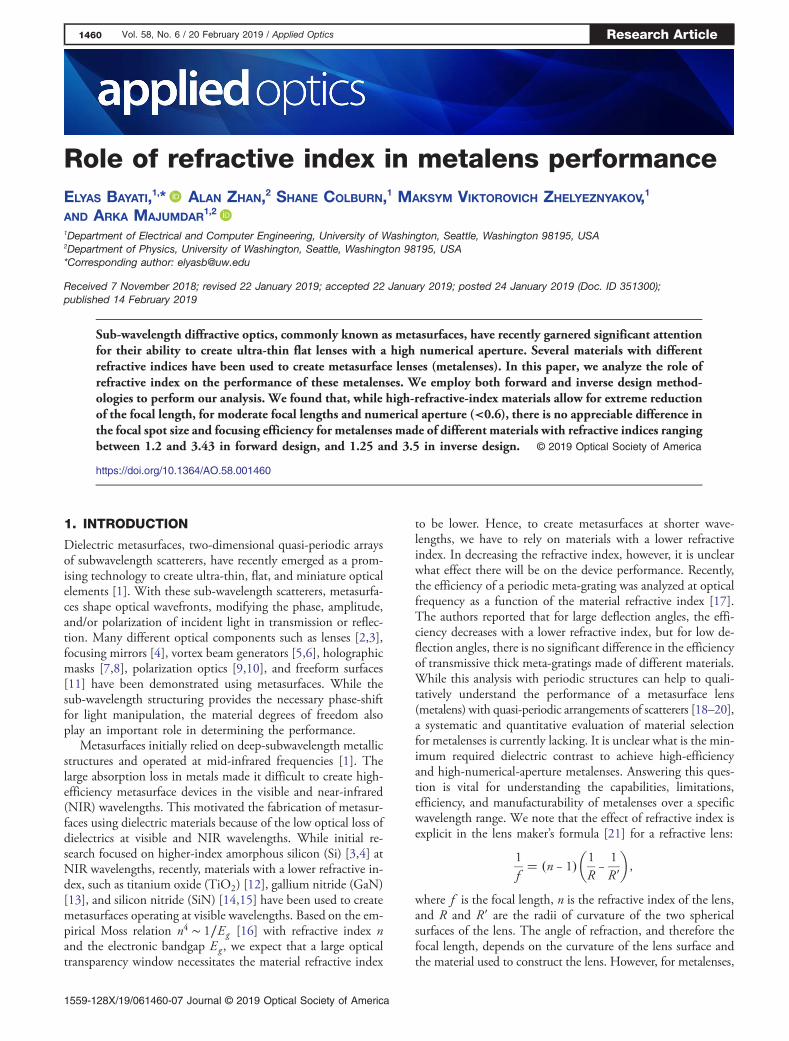
The FWHM of the focal spot is shown in Fig. 3(a) as afunction of the numerical aperture, where the solid black curveis the FWHM of a diffraction-limited spot of a lens with thesame geometric parameters. More details on the calculation ofa diffraction-limited FWHM are presented in Appendix A.There is no appreciable difference in the FWHM across therange of simulated indices, except for n � 1.2, where theFWHM does not decrease at very high numerical apertures.We define the focusing efficiency as the power within a radiusof three times the FWHM at the focal plane to the total powerincident upon the lens [3,14]. Figure 3(b) shows the focusingefficiency as a function of the refractive index of all materialsfor different numerical apertures. We find that the focusingefficiency decreases with higher numerical apertures, as ob-served before [3,14]. At low numerical apertures (NA < 0.6),the efficiency of the metalenses is almost independent of thematerial refractive index. The decrease in the efficiency withincreasing numerical aperture, however, is more drastic witha lower refractive index, and the efficiency drops faster in ma-terials with refractive indices below 1.5.
3. INVERSE DESIGN METHOD
In the forward design method, we kept the thickness-to-periodratio �t∕p� of the scatterers fixed for different materials. Thisconstraint restricts the design space and makes it difficult toobjectively compare metalenses made of different materials.Furthermore, the local phase approximation that we make ingoing from RCWA to FDTD neglects the coupling betweenthe scatterers. Such coupling is not negligible when the materialrefractive index is small. We also had to manually inspect thedata from RCWA to determine the quality of the parametersand avoid resonant dips before constructing the FDTD simu-lation. We can circumvent these problems by employing aninverse electromagnetic design methodology developed by ourgroup [26].
Recently, inverse electromagnetic design has been applied tophase profile design [7], single scatterer design [29], beam steer-ing [30], and achromatic metasurface optics [31,32]. We utilizean inverse design method using an adjoint optimization-basedgradient descent and the multi-sphere Mie theory, which de-scribes the scattering properties of a cluster of interactingspheres. We determine the interactive scattering coefficientsfor each sphere individually, similar to what the Mie theorydoes for a single sphere [33,34]. In our inverse design, wedo not make any assumption about the size of our scatterers,but we fix their periodicity. Consequently, we expect to explorea larger design space to find well-suited parameters for ourmetalens. Our simulation tool also aims to design the whole
Table 1. Metasurface Parameters Including Lattice Periodicity p and Thickness t for Each Refractive Index Used in theForward Design Method (Optical Wavelength l � 1550 nm)
Refractive Index (n) Si (n � 3.43) TiO2 (n � 2.4) GaN (n � 2.3) SiN (n � 2) SiO2 (n � 1.5) (n � 1.2)
Periodicity (p) (nm) 775 790.5 759.5 930 1372 1395Thickness (t) (nm) 1240 1317 1240 1550 2290 5022
Fig. 3. Performance of the metalens designed using the forwarddesign methodology. (a) The FWHM of the focal spot is plotted asa function of the numerical aperture of the lens. The inset plot of(a) shows a cross section of the beam size for the focal length of 50 μmwith their Gaussian fit functions. The solid and dashed curves are thediffraction-limited FWHM and guide to the eye, respectively. (b) Theefficiency of metalenses for all materials as a function of the refractiveindex for each numerical aperture using the forward design method.
1462 Vol. 58, No. 6 / 20 February 2019 / Applied Optics Research Article

metasurface and not just the unit cell, and thus the couplingbetween scatterers is already included in the design process.
Our inverse design method based on the Mie scattering,however, currently only works for spherical scatterers. Hence,in our design, we optimize the radii of different spheres. Theradii and periodicity of the metalenses are chosen to avoid anyphysical overlap or contact between adjacent spheres. We runthe optimization routine up to a fixed number of iterations(in this case 100) to obtain the final metalens. The iterationtime of the inverse design method depends on both the particlenumber and the expansion order of the orbital index l . Theexpansion order here provides the number of spherical basisfunctions for each particle to include in our simulation [26].Larger numbers of particles and expansion orders increasethe iteration time. As we are interested in sub-wavelength struc-tures to design metalenses, it is important to find a reasonablecut-off for the expansion order to balance the speed of the iter-ation and the accuracy of the result. The valid cutoff expansionorder (lmax), which is ultimately determined by the physical sizeand refractive index of the individual spheres relative to the in-cident wavelength, is chosen to be 3 in our simulations. Sincethese scattering properties are determined by the geometric andmaterial properties of the sphere, in addition to the wavelengthof the incident light, there is a relation between the cutoff ex-pansion order and possible periodicity range of the scatterers.Here, the periodicities of the metalenses are chosen in a waysuch that the contribution from expansion orders greater than3 are negligible.
We chose 10 equally spaced refractive indices between 1.25and 3.5 for the inverse design. We assume a square periodiclattice, where the spheres with different radii are placed. Forall simulations, we assume the spheres are suspended in vac-uum, and do not include a substrate. Initially, all the sphereshave identical radii. We then allow the sphere radii to vary con-tinuously between 150 nm and half of the periodicity to opti-mize the figure of merit, which is the intensity at the designedfocal point. The periodicities for all refractive indices for theinverse design method are shown in Table 2. The final radiidistribution of the optimization process for one metalens usinginverse design method is shown in Fig. 4. We find that theresult is mostly rotationally symmetric as expected for a lens.We attribute the slight asymmetry near the origin to our opti-mization running for a fixed number of iterations and converg-ing at a local minimum. The radius of the designed metalensesis 20 μm, and five focal lengths between 15 and 100 μm aretested to provide us the same number of numerical apertures forbetter comparison with forward design.
The FWHMs of the focal spots of the metalenses are shownin Fig. 5(a) as a function of the numerical aperture, where thesolid black curve is the FWHMof a diffraction-limited spot of alens with the given geometric parameters. Like the forward de-sign method, there is no appreciable difference in the FWHMacross the range of simulated indices, except at n � 1.25,where the FWHM does not decrease at very high numericalapertures. At lower numerical apertures, however, we observe
Table 2. Periodicity Values for 10 Different RefractiveIndices Used in the Inverse Design Method
RefractiveIndex (n)
Periodicity(p) (nm)
RefractiveIndex (n)
Periodicity(p) (nm)
1.25 1360 2.5 10201.5 1330 2.75 9761.75 1222 3 9122 1140 3.25 8382.25 1122 3.5 800
Fig. 4. Final radii distribution of a metalens using the inverse designmethod. Spheres are arranged in a square lattice with periodicity p.Radii of spheres are allowed to range from 150 nm to the half of theperiodicity.
Fig. 5. Performance of the metalens using the inverse designmethod. (a) The FWHM of the focal spot as a function of numericalaperture of the lens. The solid and dashed curves are the diffraction-limited FWHM and guide to the eye, respectively. (b) The focusingefficiencies of metalenses with different numerical apertures againstmaterial refractive indices in the 1.25–3.5 range using the inverse de-sign method. Different numerical apertures are specified with differentcolors, and plotted curves are guides to the eye.
Research Article Vol. 58, No. 6 / 20 February 2019 / Applied Optics 1463

that FWHMs are smaller than those of a diffracted-limitedspot. We emphasize that this is not truly breaking the diffrac-tion limit, but rather we attribute this to a larger proportion ofthe light intensity being located within side lobes as opposed towithin the central peak. By shifting power from the central peakto the side lobes, beam spot sizes that are less than the diffrac-tion-limited spot size are possible [35]. This shifting of light tothe side lobes may have arisen from the defined figure of merit,in which we did not enforce a condition on the beam spot sizeand side lobe intensity ratio. The efficiencies of these metal-enses are plotted as a function of their refractive indices inFig. 5(b), where the different numerical apertures are specifiedwith different colors. We find that the focusing efficiencydecreases with increasing numerical aperture. According toFig. 5(b), there is no significant difference in the focusing effi-ciency of high and low refractive index materials for lownumerical apertures in the range of NA � 0.2–0.37 (50–100 μm focal length). For longer numerical apertures, however,such as 0.62 and 0.8, larger refractive index materials providehigher focusing efficiency.
4. DISCUSSION
A consistent behavior is observed between forward design(Fig. 3) and inverse design (Fig. 5) regarding the relation be-tween the focusing efficiency of metalenses and their refractiveindex. For lower numerical apertures, there is no significantdifference in the focusing efficiency of metalenses with refrac-tive indices ranging from 1.25 to 3.5. However, for highernumerical apertures, achieving higher focusing efficiency metal-enses is feasible by increasing their refractive index.
On the other hand, focusing efficiencies for metalenses withdifferent numerical apertures using the inverse design methodare much smaller than the ones in the forward design method.To understand why we have such a reduction in focusing effi-ciency, we calculated the transmission phase and amplitudeof the spherical scatterers as a function of duty cycle (d∕p) forSiN as a sample material, assuming a periodic boundary con-dition (Fig. 6) and found that they cannot provide a full0-to-2π phase shift range under varying diameters of thesphere, while maintaining a high transmission amplitude. Asthese spheres are the main building block of metalenses in the
inverse design method, we cannot achieve high focusing effi-ciency for metalenses based on spherical scatterers. However,these results show that the same trend between forward design(Fig. 3) and inverse design (Fig. 5) regarding the relation be-tween the focusing efficiency of the metalenses with the refrac-tive index is not due to the actual phase or scatterer geometry,but is inherently dependent on the refractive index. Also, theFWHM of the focal spots from the inverse design method aresmaller than those in the forward design method. We attributethis to our choice of figure of merit, for which we did notenforce a condition on the beam spot size.
The performance of a metalens is related to that of a meta-surface beam deflector, which performance as a function of thematerial refractive index was recently analyzed at opticalfrequencies [17]. It was shown that while an efficiency greaterthan 80% can be obtained using high-contrast materials suchas Si and Ge, for large-angle �> 60°� beam deflection, theefficiency drops quickly for low-index materials, such as SiN.However, no significant difference in efficiency for modest de-flection angles �< 40°� was observed for different materials.Such behavior is justified by the coupled Bloch-mode analysis[17,36]. This finding is consistent with our result that for highnumerical aperture metalenses, higher refractive index materialsprovide higher efficiency, but that at low numerical apertures,there is no significant difference in performance.
5. CONCLUSION
We have evaluated low-loss dielectric materials with a widerange of refractive indices for designing metalenses using bothforward and inverse design methodologies. We found reason-able agreement between both methods in terms of the focusingefficiency and the FWHM of the focal spots on the materialrefractive indices. We found that for low numerical apertures(NA < 0.6), the efficiency of the metalenses is almost indepen-dent of the refractive index. For higher numerical apertures,however, high-index materials provide higher efficiency. Therelationship between the refractive index and the metalens per-formance is significant in choosing an appropriate material,based on considerations such as ease and scalability of manu-facturing, or a better tunability. In addition, we show that evenwith a very low refractive index �n < 2�, we can achieve rea-sonable efficiency in a metalens, which will be significant forenabling fabrication with printable photonics technologies.
APPENDIX A
The intensity profile of an ideal lens with a focal length f andradius a is given by the Airy disk [37]:
I�θ� � I o
�2J1�ka sin θ�
ka sin θ
�2
,
where I o is the maximum intensity of the central peak, J1 is thefirst order Bessel function of the first kind, k is the free spacewave vector of incident light, and θ is the angular position fromthe focal point. In this paper, the diffraction-limited FWHMfor a lens is calculated by fitting a Gaussian function (blackcurve) to the Airy disk, as shown in Fig. 7(a). In addition, wecompared the diffraction limit using both approaches (Abbediffraction limit and diffraction limit calculated by a Gaussian
Fig. 6. Amplitude and phase of the transmitted light through aspherical scatterer: using RCWA, we calculate the transmission proper-ties (red, phase delay; blue, transmission amplitude) as a function ofthe ratio of the sphere diameter and periodicity.
1464 Vol. 58, No. 6 / 20 February 2019 / Applied Optics Research Article

fit to an Airy disk) in Fig. 7(b). As it is shown in the Fig. 7(b),for high numerical apertures, our method provides a signifi-cantly smaller diffraction-limited FWHM.
Funding. Samsung; Global Research Outreach; Universityof Washington Reality Lab, Facebook, Google, and Huawei.
Acknowledgment. We thank the NVIDIA corporationfor the contribution of the GPU for our calculations in theinverse design method. In addition, we thank Amos Egel,Lorenzo Pattelli, and Giacomo Mazzamuto for allowing usto use and further contribute to CELES.
REFERENCES1. N. Yu and F. Capasso, “Flat optics with designer metasurfaces,” Nat.
Mater. 13, 139–150 (2014).2. S. Vo, D. Fattal, W. V. Sorin, Z. Peng, T. Tran, M. Fiorentino, and R. G.
Beausoleil, “Sub-wavelength grating lenses with a twist,” IEEEPhoton. Technol. Lett. 26, 1375–1378 (2014).
3. A. Arbabi, Y. Horie, A. J. Ball, M. Bagheri, and A. Faraon, “Subwavelength-thick lenses with high numerical apertures and large efficiency based onhigh-contrast transmitarrays,” Nat. Commun. 6, 7069 (2015).
4. D. Fattal, J. Li, Z. Peng, M. Fiorentino, and R. G. Beausoleil, “Flat di-electric grating reflectors with focusing abilities,” Nat. Photonics 4,466–470 (2010).
5. Y. Yang, W. Wang, P. Moitra, I. I. Kravchenko, D. P. Briggs, and J.Valentine, “Dielectric meta-reflectarray for broadband linear polariza-tion conversion and optical vortex generation,” Nano Lett. 14, 1394–1399 (2014).
6. G. Li, M. Kang, S. Chen, S. Zhang, E. Y.-B. Pun, K. W. Cheah, and J.Li, “Spin-enabled plasmonic metasurfaces for manipulating orbital an-gular momentum of light,” Nano Lett. 13, 4148–4151 (2013).
7. G. Zheng, H. Mühlenbernd, M. Kenney, G. Li, T. Zentgraf, and S.Zhang, “Metasurface holograms reaching 80% efficiency,” Nat.Nanotechnol. 10, 308–312 (2015).
8. X. Ni, A. V. Kildishev, and V. M. Shalaev, “Metasurface holograms forvisible light,” Nat. Commun. 4, 2807 (2013).
9. N. Yu, F. Aieta, P. Genevet, M. A. Kats, Z. Gaburro, and F. Capasso,“A broadband, background-free quarter-wave plate based on plas-monic metasurfaces,” Nano Lett. 12, 6328–6333 (2012).
10. A. Arbabi, Y. Horie, M. Bagheri, and A. Faraon, “Dielectric metasur-faces for complete control of phase and polarization with subwave-length spatial resolution and high transmission,” Nat. Nanotechnol.10, 937–943 (2015).
11. A. Zhan, S. Colburn, C. M. Dodson, and A. Majumdar, “Metasurfacefreeform nanophotonics,” Sci. Rep. 7, 1673 (2017).
12. M. Khorasaninejad, W. T. Chen, A. Y. Zhu, J. Oh, R. C. Devlin, C.Roques-Carmes, I. Mishra, and F. Capasso, “Visible wavelengthplanar metalenses based on titanium dioxide,” IEEE J. Sel. Top.Quantum Electron. 23, 43–58 (2017).
13. Z. Wang, S. He, Q. Liu, and W. Wang, “Visible light metasurfacesbased on gallium nitride high contrast gratings,” Opt. Commun. 367,144–148 (2016).
14. A. Zhan, S. Colburn, R. Trivedi, T. K. Fryett, C. M. Dodson, and A.Majumdar, “Low-contrast dielectric metasurface optics,” ACS Photon.3, 209–214 (2016).
15. S. Colburn, A. Zhan, E. Bayati, J. Whitehead, A. Ryou, L. Huang, andA. Majumdar, “Broadband transparent and CMOS-compatible flat op-tics with silicon nitride metasurfaces,” Opt. Mater. Express 8, 2330–2344 (2018).
16. R. R. Reddy and Y. N. Ahammed, “A study on the Moss relation,”Inf. Phys. Technol. 36, 825–830 (1995).
17. J. Yang and J. A. Fan, “Analysis of material selection on dielectricmetasurface performance,” Opt. Express 25, 23899–23909 (2017).
18. P. Lalanne and P. Chavel, “Metalenses at visible wavelengths: past,present, perspectives,” Laser Photon. Rev. 11, 1600295 (2017).
19. H. Liang, Q. Lin, X. Xie, Q. Sun, Y. Wang, L. Zhou, L. Liu, X. Yu, J.Zhou, T. F. Krauss, and J. Li, “Ultrahigh numerical aperture metalensat visible wavelengths,” Nano Lett. 18, 4460–4466 (2018).
20. R. Paniagua-Dominguez, Y. F. Yu, E. Khaidarov, S. Choi, V. Leong,R. M. Bakker, X. Liang, Y. H. Fu, V. Valuckas, L. A. Krivitsky, andA. I. Kuznetsov, “A metalens with a near-unity numerical aperture,”Nano Lett. 18, 2124–2132 (2018).
21. F. A. Jenkins and H. E. White, Fundamentals of Optics (McGraw-HillEducation, 1937).
22. F. T. Chen and H. G. Craighead, “Diffractive phase elements based ontwo-dimensional artificial dielectrics,” Opt. Lett. 20, 121–123 (1995).
23. R. Søndergaard, M. Hösel, D. Angmo, T. T. Larsen-Olsen, and F. C.Krebs, “Roll-to-roll fabrication of polymer solar cells,”Mater. Today 15(1–2), 36–49 (2012).
24. F. T. Chen and H. G. Craighead, “Diffractive lens fabricated withmostly zeroth-order gratings,” Opt. Lett. 21, 177–179 (1996).
25. V. Liu and S. Fan, “S4: a free electromagnetic solver for layered peri-odic structures,” Comput. Phys. Commun. 183, 2233–2244 (2012).
26. A. Zhan, T. K. Fryett, S. Colburn, and A. Majumdar, “Inverse design ofoptical elements based on arrays of dielectric spheres,” Appl. Opt. 57,1437–1446 (2018).
27. W. Stork, N. Streibl, H. Haidner, and P. Kipfer, “Artificial distributed-indexmedia fabricated by zero-order gratings,”Opt. Lett. 16, 1921–1923 (1991).
28. D. Rosenblatt, A. Sharon, and A. A. Friesem, “Resonant grating wave-guide structures,” IEEE J. Quantum Electron. 33, 2038–2059 (1997).
29. D. Sell, J. Yang, S. Doshay, R. Yang, and J. A. Fan, “Large-angle,multifunctional metagratings based on freeform multimode geom-etries,” Nano Lett. 17, 3752–3757 (2017).
30. K. Wang, J. Zhao, Q. Cheng, and T. J. Cui, “Broadband andbroad-angle low-scattering metasurface based on hybrid optimizationalgorithm,” Sci. Rep. 4, 5935 (2014).
31. F. Aieta, M. A. Kats, P. Genevet, and F. Capasso, “Multiwavelengthachromatic metasurfaces by dispersive phase compensation,”Science 347, 1342–1345 (2015).
32. R. Pestourie, C. Pérez-Arancibia, Z. Lin, W. Shin, F. Capasso, andS. G. Johnson, “Inverse design of large-area metasurfaces,” Opt.Express 26, 33732–33747 (2018).
Fig. 7. (a) Example of a Gaussian fit to an Airy disk, which is gen-erated by an ideal lens under the illumination by 1550 nm with a focallength of 50 μm and a radius of 40 μm. (b) The diffraction-limitedFWHM of the focal spot as a function of numerical aperture of thelens. The dashed curve is the diffraction-limited FWHM using theAbbe diffraction limit approximation, and the solid curve is the dif-fraction limit calculated by a Gaussian fit to an Airy disk.
Research Article Vol. 58, No. 6 / 20 February 2019 / Applied Optics 1465

33. D. W. Mackowski and M. I. Mishchenko, “Calculation of the T matrixand the scattering matrix for ensembles of spheres,” J. Opt. Soc. Am.A 13, 2266–2278 (1996).
34. A. Egel, L. Pattelli, G. Mazzamuto, D. S. Wiersma, and U. Lemmer,“CELES: CUDA-accelerated simulation of electromagnetic scatteringby large ensembles of spheres,” J. Quant. Spectrosc. Radiat. Transfer199, 103–110 (2017).
35. A. A. Maznev and O. B. Wright, “Upholding the diffraction limit in thefocusing of light and sound,” Wave Motion 68, 182–189 (2017).
36. J. Yang, D. Sell, and J. A. Fan, “Freeform metagratings based oncomplex light scattering dynamics for extreme, high efficiency beamsteering,” Ann. Phys. 530, 1700302 (2018).
37. T. D. Gerke and R. Piestun, “Aperiodic volume optics,” Nat. Photonics4, 188–193 (2010).
1466 Vol. 58, No. 6 / 20 February 2019 / Applied Optics Research Article