role of solid state diffusion studies in materials ... · department of materials science and...
TRANSCRIPT
Role of Solid State Diffusion Studies in Materials Selection and Process Design for
Development of Low Enrichment U-Mo Metallic Nuclear Fuel Systems
Y.H. Sohn
Professor and Associate Director*
Department of Materials Science and Engineering
*Advanced Materials
Processing and Analysis Center
University of Central
Florida, Orlando, FL, USA

��
U-Mo Fuel for RERTR/GTRI U-Mo Fuel: • Developed for the program of Reduced Enrichment for Research and Test
Reactor (RERTR) – named Global Threat Reduction Initiative (GTRI) • Dispersed or laminated in aluminum or Al alloy
RERTR/GTRI: • Convert research and test reactor from using HEU fuels to LEU fuels • Increase density of U isotopes in the fuel
Al
UMo
U-10wt.%Mo vs Al after irradiation**
U-Mo fuel particles Al alloy matrix Al alloy cladding
Dispersion Fuel
U-Mo fuel plate Al alloy cladding
Monolithic Fuel

��
Fuel-Matrix and Fuel-Cladding Chemical Interaction
Fuel-Matrix and Fuel-Cladding Chemical Interaction (FMCI and FCCI)
• Induced by interdiffusion • Involves multiple-phases and multiple-components. • Irradiation enhanced diffusion
Deleterious effects: • Thins the cladding layer • Produces phases with relative low melting point • Cause cracks due to different thermal expansion coefficients
Engineering Solutions that Require Scientific Understanding: • Addition of alloying constituents for matrix/cladding • Placement of barrier layer (or coatings) between metallic fuel
and matrix/cladding alloys • Diffusional interaction between barrier and fuel as well as
matrix/cladding alloys

��
Materials Research at MCEE ! RERTR/GTRI:
" U-Mo vs. Al Matrix/Cladding Alloys " U-Mo vs. Diffusion Barrier (e.g., Zr, Mo, Nb, Mg) " Zr Barrier vs. Al Cladding Alloys
! FCRD: " U-Zr vs. Fe, Fe-Cr, Fe-Cr-Ni Alloys " Fe, Fe-Cr, Fe-Cr-Ni Thin Films on U-Zr " Thermotransport in U-Zr Alloys
! ATR/NSUF " Neutron Irradiation of
Diffusion Couples with U
! Diffusion in Mg Alloys for Lightweight
! Microstructural Development / Diffusion " Ni-Mn-Ga and Ni-Mn-In Magnetocaloric Materials " Multiscale (e.g., Nano and Mirco) Al- and Mg-Metal Matrix
Composites " Thermal Barrier Coatings for Gas Turbines " High Temperature Heat Transfer Fluid Corrosion
5 1/nm5 1/nm
NiMnGa M-T

Current Research Activity at MCEE View by Periodic Chart
Major Solvent Alloying Addition Model Only

��
Outline ! Brief Experimental Details
! Diffusion related to U-Mo and Al-alloy matrix/cladding in dispersion fuels
! Diffusion barrier kinetics for Zr, Mo, Nb, and Mg in monolithic fuels
! Process design for Zr diffusion barrier: • Microstructural characterization of HIP
fuel plates • U-Mo-Zr diffusion kinetics and phase
equilibria study with quench variation • Zr interaction with Al-alloy cladding
! Summary and future work

�
Experimental Details
• Solid-to-solid diffusion couple alloys were cut, polished and assembled under a controlled Ar atmosphere in a glove box.
• Diffusion couples were encapsulated in quartz capsules in Ar atmospheres after Ar flush for heat treatment.
• Diffusion anneal performed using a Lindberg/Blue 3-Zone horizontal tube furnace.
• After anneal the couples were quenched in ice water to preserve the high temperature microstructures.
• The diffusion couples were mounted in epoxy, cross-sectioned and polished for analysis.
Clamping diskAl2O3 spacer disk
Alloy disk

�
Experimental Details

��
Diffusion Couples:
U-Mo vs. Al* U-Mo vs. Al-Si**
U vs. Mo***
*"Perez,"et"al."Metall."Mater."Trans."A,"2011;"42A:"3071."
**"Perez,"et"al."Metall."Mater."Trans."A,"2013;"44A:"584."
***"K."Huang,"et"al.,"Metall."Mater."Trans."A,"2013;"44A:"738.""
Diffusion Investigations in U-Mo-Al-Si for RERTR Dispersion Fuels
Diffusion(Couples((wt.%)
Temperature((°C)
Time((hours)
U"7Mo"vs."Al"
U10Mo"vs."Al"
U12Mo"vs."Al 600 24
U"7Mo"vs."Al"
U10Mo"vs."Al"
U12Mo"vs."Al 550
1 5 20
U"7Mo"vs."AlC2Si"
U10Mo"vs."AlC2Si"
U12Mo"vs."AlC2Si 550
1 5 20
U"7Mo"vs."AlC5Si"
U10Mo"vs."AlC5Si"
U12Mo"vs."AlC5Si 550
1 5 20

���
U-Mo vs. Al Diffusion Couples*
• Separation of the interdiffusion zone into different phase regions takes place during anneal to produce a stratified structure.
• Multi-phase regions composed of various intermetallic phases develop.
• Similar microstructures are observed in diffusion couples annealed at 600˚C and 550˚C.
10µm 10µm 10µm10µm
α-U
UAl3U6Mo4Al43
UAl3UMo2Al20U6Mo4Al43UAl3
UMo2Al20U6Mo4Al43
UAl4UMo2Al20
UAl3U6Mo4Al43
UAl3 UMo2Al20 U6Mo4Al43
!-U
UAl3 U6Mo4Al43
U-10Mo vs. Al
UAl4 UMo2Al20
100 µm
(600°C, 24hrs)
• Perez,"et"al."Metall."Mater."Trans."A"2011;42:3071."

���
• The interdiffusion zone developed a fine-grained microstructure with grains size less than 1µm.
• Electron diffraction analyses were carried out for selected regions in the interdiffusion zone of the U-10Mo vs. Al diffusion couple annealed at 600˚C for 24 hours.
• The UAl3, UAl4, U6Mo4Al43 and UMo2Al20 phases were identified in the interdiffusion zone in multi-phase layered microstructures.
022
220
242
440
[111]
UAl4Orthorhombic, Imma
100 200
110
[001]210
UAl3Cubic, Pm-3m
220
[111]
UMo2Al20Cubic, Fd-3m
422202
022
404
224[042]
200400
012
024 212
U6Mo4Al43(P63/mcm3(193))
U-Mo vs. Al Diffusion Couples*
• Perez,"et"al."Metall."Mater."Trans."A"2011;42:3071."

���
U-Mo vs. Al-Si Diffusion Couples*
• Diffusion couples containing Si in the Al-alloys showed stratification of the interdiffusion zone.
• Complex multi-phase regions developed within 1 hour anneal time. • Initially discontinuous Al and Si-rich layers develop in the
interdiffusion zone. • After longer diffusion anneal, the observed Si-rich regions grow and
develop into continuous layers.
U-12Mo vs. Al-2Si (550°C for 1 hour)
U-12Mo vs. Al-2Si (550°C for 5 hours)
U-12Mo vs. Al-2Si (550°C for 20 hours)
25µm 25µm 25µm
Si-rich
Al-rich
Si-rich
Al-rich
Si-rich
Al-rich
*"Perez,"et"al."Metall."Mater."Trans."A,"2013;"44A:"584."
"
���
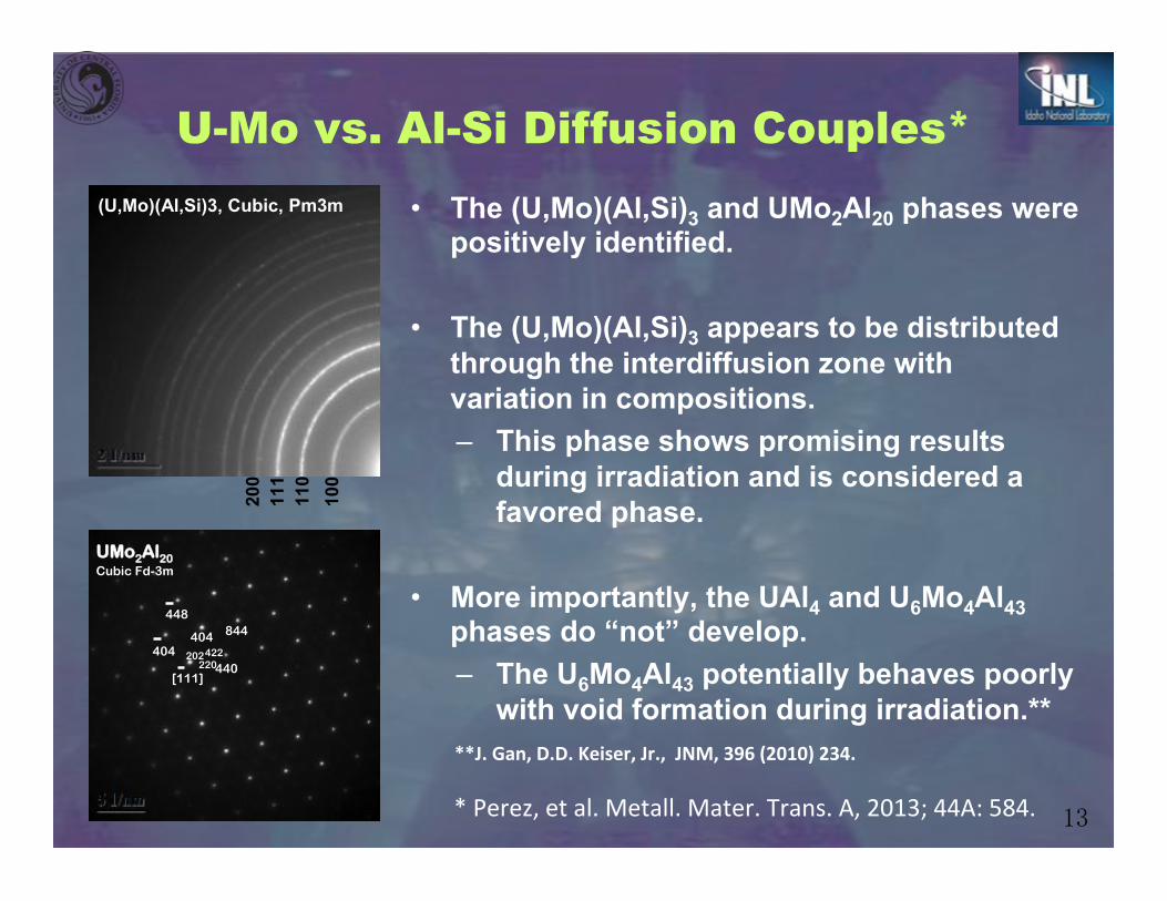
• The (U,Mo)(Al,Si)3 and UMo2Al20 phases were
positively identified.
• The (U,Mo)(Al,Si)3 appears to be distributed through the interdiffusion zone with variation in compositions. – This phase shows promising results
during irradiation and is considered a favored phase.
• More importantly, the UAl4 and U6Mo4Al43 phases do “not” develop. – The U6Mo4Al43 potentially behaves poorly
with void formation during irradiation.**
(U,Mo)(Al,Si)3, Cubic, Pm3m
100
110
111
200
UMo2Al20Cubic Fd-3m
440
404 844448
404220
202422
[111]
**J.(Gan,(D.D.(Keiser,(Jr.,((JNM,(396((2010)(234.(
U-Mo vs. Al-Si Diffusion Couples*
*"Perez,"et"al."Metall."Mater."Trans."A,"2013;"44A:"584."
���
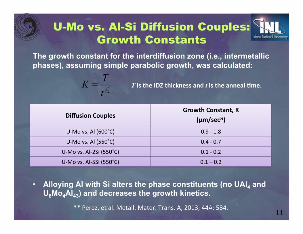
U-Mo vs. Al-Si Diffusion Couples: Growth Constants
The growth constant for the interdiffusion zone (i.e., intermetallic phases), assuming simple parabolic growth, was calculated:
21tTK =
Diffusion(Couples(Growth(Constant,(K(
(µm/sec½)(
UCMo"vs."Al"(600˚C)" 0.9"C"1.8"
UCMo"vs."Al"(550˚C)" 0.4"C"0.7"
UCMo"vs."AlC2Si"(550˚C)" 0.1"C"0.2"
UCMo"vs."AlC5Si"(550˚C)" 0.1"–"0.2"
T(is(the(IDZ(thickness(and(t(is(the(anneal(Ome.(
• Alloying Al with Si alters the phase constituents (no UAl4 and
U6Mo4Al43) and decreases the growth kinetics.
**"Perez,"et"al."Metall."Mater."Trans."A,"2013;"44A:"584."

���
Diffusion Database
BSE micrograph and concentration profile from the U vs. Mo couple annealed at 1273K for 24 hours.
U XK MoXI
150$µm
00.10.20.30.40.50.60.70.80.9
1
-800 -700 -600 -500 -400 -300 -200 -100 0 100
FittedMeasurement 1 EPMAMeasurement 2 EPMA
XK = -70
Distance to Matano Plane, x (µm)
Con
cent
ratio
n of
Mo
(at.
frac
.)
X0
0 0.05 0.1 0.15 0.2 0.25 0.3 0.35 0.4
Inte
rdiff
usio
n C
oeff
icie
nt (m
2 /s) 1273K this study
1173K this study1073K this study973K this study923K this study1323K Adda.1273K Adda.1223K Adda.1123K Adda.
NMo (atomic fraction)
10-11
10-12
10-13
10-14
10-15
10-16
10-17
1050 1100 1150 1200 1250 1300 1350
Trac
er d
iffus
ivity
of U
(m2 /s
)
Temperature (K)
Exp. Pure U by AddaExp. Nmo=0.1 by AddaIdeal/CALPHAD/Subreg. Sol.Reg. Sol.Vamberskii
NMo=0NMo=0.08
NMo=0.07
NMo=0.1
NMo=0.06
10-11
10-12
10-13
10-14
Interdiffusion Coefficient Tracer Diffusion Coefficients
K."Huang,"et"al.,"Metall."Mater."Trans."A,"2013;"44A:"738.""
���
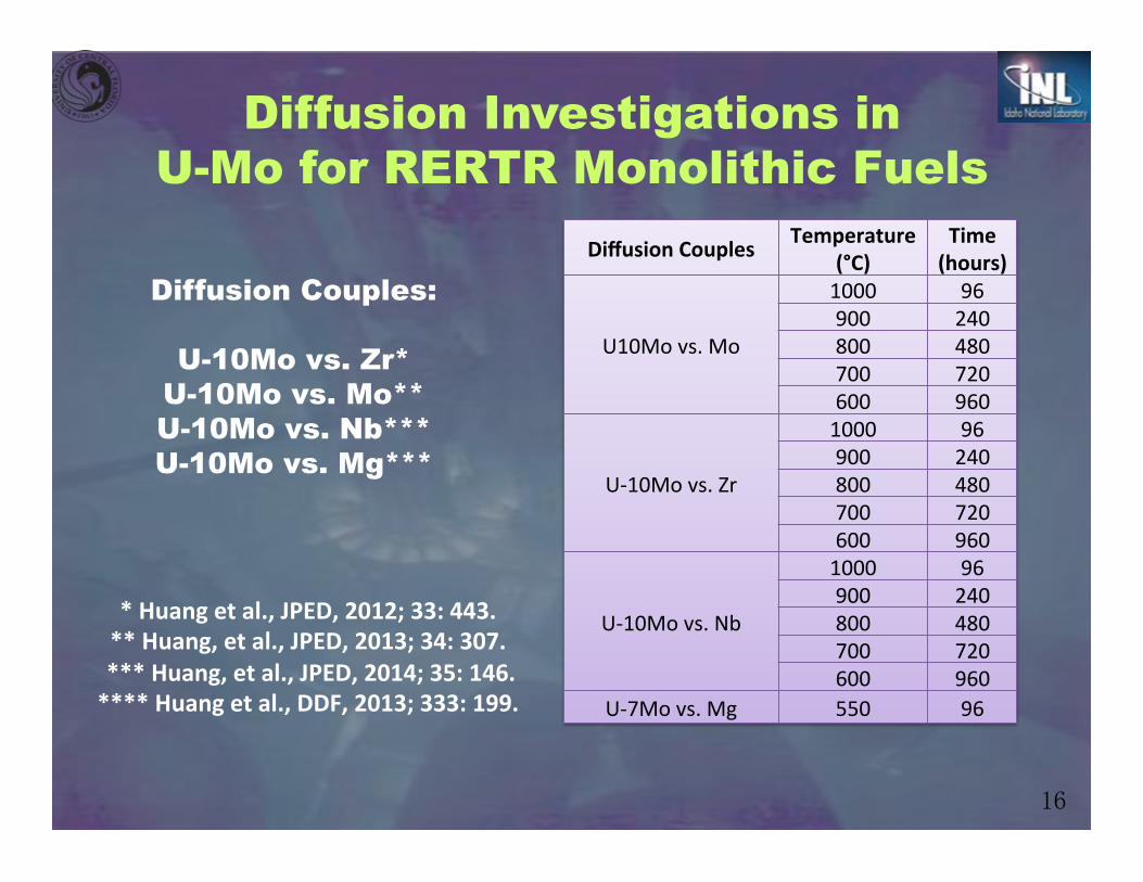
Diffusion Couples:
U-10Mo vs. Zr* U-10Mo vs. Mo** U-10Mo vs. Nb*** U-10Mo vs. Mg***
Diffusion Investigations in U-Mo for RERTR Monolithic Fuels
*(Huang(et(al.,(JPED,(2012;(33:(443.(**(Huang,(et(al.,(JPED,(2013;(34:(307.((***(Huang,(et(al.,(JPED,(2014;(35:(146.(****(Huang(et(al.,(DDF,(2013;(333:(199.(
(
Diffusion(Couples Temperature((°C)
Time((hours)
U10Mo"vs."Mo
1000 96 900 240 800 480 700 720 600 960
UC10Mo"vs."Zr
1000 96 900 240 800 480 700 720 600 960
UC10Mo"vs."Nb
1000 96 900 240 800 480 700 720 600 960
UC7Mo"vs."Mg 550 96

��
Barrier Materials Candidates Refractory element Zr, Mo and Nb*: ! Diffusion of U is slow. ! High melting points and thermal conductivity ! Corrosion resistant is good. Mo: ! Maintain the system to be simple binary. ! One intermetallic phase forms between U-Mo and Mo. ! Largest variation in the composition of U-10wt.%Mo fuel can be less than
15 at.% Mo. Zr: ! Neutrons adsorption rate is one of the lowest among natural metal [4]. ! Compatible with current hot rolling process
adopted by Idaho National Lab (INL)**. Nb: ! Forms complete solid solution with U ! Forms less number of intermetallic phases with Al compared to Zr and Mo.
*Davis Jr, et al. ASM Handbook 1992. **Perez, et al. J Nucl Mater 2010;402:8
U Mo
Tem
pera
ture
( ℃)
U-10wt.%Mo

��
0
10
20
30
40
50
60
70
80
90
100
UMoZr
U-Mo α-Zr
Zr rich phase
Mo2Zr β-Zr
150$µm
800⁰C 480 hours
Diffusion path: 800 °C(Phase diagram: 750 °C)
MeasuredEstimated
Diffusion Microstructure and Diffusion Paths: U-Mo vs. Zr
! Boned well at 1000 -600⁰C. ! γ-U, Mo2Zr, Zr rich, two phases
region, pure Zr were observed. ! Mo2Zr gets denser when anneal
temperature decreased according to the phase diagrams.
! Uphill diffusion of U. ! The estimated diffusion paths
agree well with the ternary phase diagram.
! Mo plays a significant role on the diffusion path especially at 700°C.
! About 104-102 times slower than those between U-10wt.%Mo vs. Al and Al-Si, respectively.

���
U-Mo MoXI
50#µm900°C for 240 hrs
0
0.1
0.2
0.3
0.4
0.5
0.6
0.7
0.8
0.9
1
-300 -250 -200 -150 -100 -50 0 50
Con
cent
rati
on o
f M
o (a
t. f
rac.
)
Distance to Matano plane (µm)
EPMA 1EPMA 2Smoothed
X0 XI =8.5
IZ=144
900°C"for"240"hrs""
Diffusion Microstructure and Diffusion Paths: U-Mo vs. Mo
0 0.1 0.2 0.3 0.4 0.5
Inte
rdiff
usio
n co
effic
ient
(m2 /s
)
NMo (at. frac.)
This study 1000 °CThis study 900 °CThis study 800 °CPrevious study 1000 °CPrevious study 900 °CPrevious study 800 °C
10-12
10-13
10-14
10-15
10-16
! Boned well at 1000 -600⁰C. ! No intermetallics formation. ! Atomic mobility and vacancy wind
parameters determined for U-Mo solid solution.
! More than 105 times slower than those between U-10wt.%Mo vs. Al and Al-Si, respectively.

���
800⁰C"480"hours""
U10Mo
U-Mo-Nb S.S
Pure U
Nb
Thermal crack
30#µm
IZ
Diffusion Microstructure and Diffusion Paths: U-Mo vs. Nb
! Intermetallic formation and growth. ! Significant quench cracks after all
temperatures of anneal. ! More than 106 times slower than
those between U-10wt.%Mo vs. Al and Al-Si, respectively.
10-12
10-13
10-14
10-15
10-16
10-17
10-18
10-190.6 0.8 1 1.2 1.4 1.6 1.8
Gro
wth
rat
e (m
2 /s)
1000/T(K)
U"Mo%vs.%Zr%(measured)U"Mo%vs.%Zr%(predicted)U"Mo%vs.%Mo%(measured)U"Mo%vs.%Mo%(predicted)U"Mo%vs.%Nb%(measured)U"Mo%vs.%Nb%(predicted)
10-11
The growth rate of interdiffusion zone between U-10Mo with Zr, Mo, Nb is about 104, 105 and 106 times slower than those in diffusion couples of U-10Mo vs. Al or Al-Si, respectively.

���
Mg: ! There is no reactions between Mg with U or Mo based on binary phase
diagram. ! Reaction between Mg and Al alloy is insignificant during improved hot
rolling process at 275°C reported*. ! The neutron absorption rate of Mg is one of the lowest among natural
metal**. ! Thermal conductivity is high, 156 W·m−1·K−1 .
*Wiencek TC, et al. 1998 International Meeting on RERTR. São Paulo, Brazil, 1998. **Davis Jr, et al. ASM Handbook 1992.
Barrier Materials Candidates

���
Diffusion Microstructure and Diffusion Paths: U-Mo vs. Mg
U7Mo
150$µm
MgXI
560⁰C(96(hours((
Mg
U-7Mo
Mg
U-7Mo
0
10
20
30
40
50
60
70
80
90
100
0 50 100 150 200 250 300 350 400
Conc
entra
tion (
at.%
)
Distance (nm)
U"
Mo"
Mg"
O"

���
Zr Diffusion Barrier
Rolled, HIP’ed and Annealed Fuel Assembly*
U-Mo-Zr Diffusion Kinetics and
Phase Equilibria**
Zr vs. Al-Alloy Cladding*** *Y.(Park(et(al.,(Journal(of(Nuclear(Materials,(2014;(447:(215.(**Y.(Park(et(al.,(and(N.(Eriksson(et(al.,(Unpublished.(***J.(Dickson(et(al.,(Intermetallics,(2014;(49:(154.((***A.(Paz(y(Puente,(et(al.,((J.(Ref.(Met.(Hard(Mater.,(2014;(43:(317.((

���
! U-Mo alloy by arc-melting. ! Acid cleaned and laminated, in a carbon steel can, using pure Zr
(99.9% pure) foil with a starting thickness of 250 µm. ! The Zr-laminated U-Mo coupon: pre-heated at 650°C for 30 minutes in
a furnace, and co-rolled 15 times. A post-rolling annealing treatment was performed at 650°C for 45 minutes.
! Each laminated foil was polished and stacked with AA6061 cladding. ! HIP’ed at various temperatures (520, 540, 560 and 580°C) and
durations (45, 60, 90 180 and 345 minutes) ! The HIP heated to the target temperature with a ramp-up and cool-
down rate of 280°C per hour with constant pressure at 103 MPa (~15 ksi) using argon pressurizing medium.
Rolled, HIP’ed and Annealed Fuel Assembly"
250 µm!
25 µm!
330 µm!Zr U-Mo Alloy
AA6061
AA6061
HIP Pressure 103 MPa (15 ksi)
HIP Pressure 103 MPa (15 ksi)

���
Rolled, HIP’ed and Annealed Fuel Assembly"
250 µm!
25 µm!
330 µm!Zr U-Mo Alloy
AA6061
AA6061
HIP Pressure 103 MPa (15 ksi)
HIP Pressure 103 MPa (15 ksi)
Can we employ higher HIP temperature and longer HIP duration?
Improved adhesion strength, but want
to avoid excessive diffusional interactions.

���
Diffusion Barrier: Zr Rolled, HIP’ed and Annealed Fuel Assembly
HIP(Run� Sample� Temperature((˚C)� Hold(Time(((minute)� Pressure((ksi)�
81a� 81d4� 560� 90� 15�
82� 82d5� 580� 90� 15�
83� 83d5� 540� 90� 15�
84� 84d4� 520� 90� 15�
85� 85d5� 560� 180� 15�
86� 86d5� 560� 45� 15�
87� 87d5� 560� 345� 15�
88� 88d5,(88d2b� 560� 60� 15�
N/A� Alloy(402d2� 650� 90� (�
UdMo/Zr/6061(foils(codrolled(at(650˚C(for(90(minutes.

��
AA6061 Zr
U10Mo
AA6061
Zr
U10Mo
100 µm
2 µm
Diffusion Barrier: Zr Rolled, HIP’ed and Annealed Fuel Assembly
U10Mo
UZr2
Mo2Zr
Zr
AA6061
Al3Zr
α-U
Zr
2 µm
2 µm

��
U-Mo vs. Zr Interface"
(Al,Si)3Zr (tI16)
(Al,Si)2Zr (hP12)
6061 vs. Zr Interface"
UZr2
Zr
Mo2Zr
α-U
γ-U(Mo)
UZr2 (hP3)
Mo2Zr (cF24)
U(α-U) (oC4)
Diffusion Barrier: Zr Rolled, HIP’ed and Annealed Fuel Assembly

���
Hold(Ome(=(90(min.
Hold(Ome(=(90(min.
Hold(Ome(=(90(min.
Hold(Ome(=(90(min.
Diffusion Barrier: Zr Rolled, HIP’ed and Annealed Fuel Assembly

���
Thold(=(560˚C"
Thold(=(560˚C"
Thold(=(560˚C"
Thold(=(560˚C"
Diffusion Barrier: Zr Rolled, HIP’ed and Annealed Fuel Assembly

���
! Negligible diffusional interaction for U-Mo / Zr interface during HIP – most interactions occur during rolling process (650°C).
! Arrhenius temperature dependence for 6061 / Zr Interface - Rolling: 473.30 kJ/mol and Transverse: 473.83 kJ/mol.
Diffusion Barrier: Zr Rolled, HIP’ed and Annealed Fuel Assembly
���
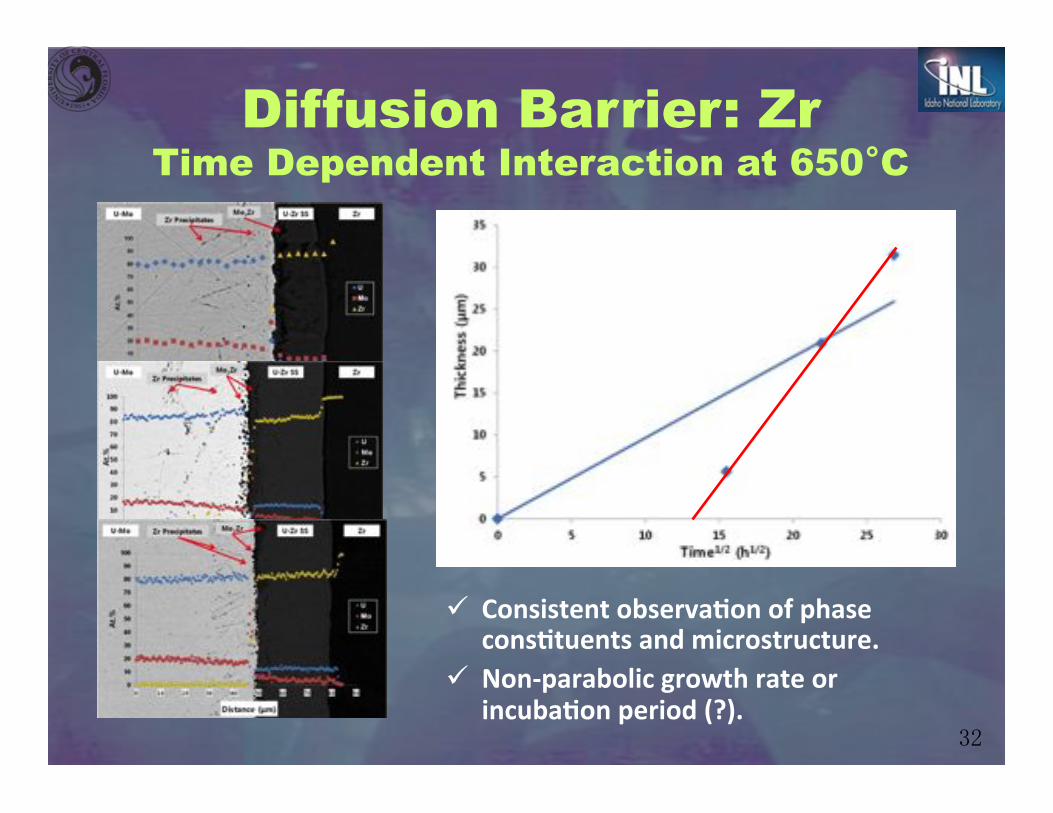
Diffusion Barrier: Zr Time Dependent Interaction at 650°C
" Consistent(observaOon(of(phase(consOtuents(and(microstructure.(
" Nondparabolic(growth(rate(or(incubaOon(period((?).(

���
Diffusion Barrier: Zr Negligible Interaction at 600°C (960 hrs)
1EC18"
1EC17"
1EC16"
1EC15"
1EC14"
1EC13"
1EC12"
1EC11"
0.7" 0.8" 0.9" 1" 1.1" 1.2"Grow
th(Con
stan
t((m2/s)(
1000/T((1/K)(
! On-going study on U-Mo-Zr diffusional interactions at lower temperature (650°C to 520°C) as a function of time.

���
Diffusion Barrier: Zr Phase Equilibria of U-Mo-Zr
900°C for 168 hr Water Quenched
650°C for 3 hrs Water Quenched
Water Quenched
560°C for 1.5 hrs
Furnace Cooled
Air Cooled
Alloys
U-10Mo U-10Mo-0.5Zr U-10Mo-1Zr U-10Mo-2Zr U-10Mo-5Zr
U-10Mo-10Zr U-10Mo-20Zr
Quantitative Analyses
XRD, SEM-Image
Analysis

���
Diffusion Barrier: Zr Phase Equilibria of U-Mo-Zr
1 U10Mo2 U10Mo.5Zr3 U10Mo1Zr4 U10Mo2Zr5 U10Mo5Zr6 U10Mo10Zr7 U10Mo20Zr
0"
200"
400"
600"
800"
30" 40" 50" 60" 70" 80"
U10Mo5Zr)
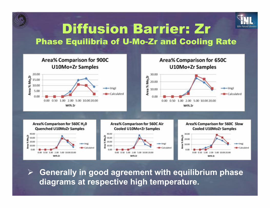
Diffusion Barrier: Zr Phase Equilibria of U-Mo-Zr and Cooling Rate
! Generally in good agreement with equilibrium phase diagrams at respective high temperature.

��
The(binary(phase(diagram(indicates(the(formaOon(of(many(possible(intermetallics(in(the(temperature(range(of(interest.(
Low(TE(=(660°C((
Diffusion Barrier: Zr Zr vs. Al Alloys Diffusion Couples
Familiar System but Unusual Observations

��
Excellent(agreement(with(previously(reported((e.g.,(Kidson,(1964;(Laik,(2004)(kineOcs(at(temperature(above(525°C.(
*J.(Dickson(et(al.,(Intermetallics,(2014;(49:(154.((
Diffusion Barrier: Zr Zr vs. Al Alloys Diffusion Couples

���
Diffusion Barrier: Zr Zr vs. Al Alloys Diffusion Couples
Al2Si(
Zr(τ1((Al5SiZr2)((
2 1/nm2 1/nm
0"2"0"
1"1"0"[0"0"1]"
(Si,Al)2Zr+–+oC12+
5 1/nm5 1/nm
1"1"4"
1"1̅"4"[4"0"1̅]"
Al2Si+
(Si,Al)2Zr+
τ1+(Al5SiZr2)+2+tI16+++
τ1+(Al5SiZr2)++
1"μm"
Zr (Al,Si)3Zr Al3SiZr2 Al2Zr
5 1/nm5 1/nm
1"1"4"1"1̅"4"
[4"0"1̅]"
(Al,Si)3Zr+–+tI16+
5 1/nm5 1/nm
2"1̅"0"1"1"2"
[2"4"3̅]"
Al3SiZr2+–+hP12++
" FormaOon(and(growth(of(τ1((Al5SiZr2)(ternary(intermetallic(phase.(
" Similar(for(Al5Si(Alloy.(
*J.(Dickson(et(al.,(Intermetallics,(2014;(49:(154.((

���
Diffusion Barrier: Zr Zr vs. Al Alloys Diffusion Couples
0"
10"
20"
30"
40"
50"
60"
70"
80"
90"
100"
0" 50" 100" 150" 200"
Concen
tra)
on*(a
t.%)*
Distance*(μm)*
(Al,Si)3Zr*τ1**
Al*
Zr*
Si* (Al,Si)2Zr*
Zr#Al# Al3Zr# Al2Zr#
Zr#Al(Si#Alloy#
τ1#(Al5SiZr2)#
(Al,Si)3Zr#
Zr#AA6061# (Al,Si)3Zr#
(Si,Al)2Zr#Al2Zr#
τ1#(Al5SiZr2)# (Al,Si)2Zr#
Al3SiZr2#
" FormaOon(and(growth(of(both(τ1((Al5SiZr2)(ternary(intermetallic(and(binary((Al,Si)3Zr(phases.(
" DisOnguished(by(Si(content.(
*J.(Dickson(et(al.,(Intermetallics,(2014;(49:(154.((

���
Unusual(behavior(at(lower(temperature.(
625°C&
560°C&
525°C&
425°C& 450°C& 425°C&
1E-17
1E-16
1E-15
1E-14
1E-13
1E-12
1.10 1.15 1.20 1.25 1.30 1.35 1.40 1.45
k (
m2/s)
1000/T(K)
High Temperature
Low Temperature
Dickson(et(al.,(Unpublished(Research.(
Diffusion Barrier: Zr Zr vs. Al Alloys Diffusion Couples

���
1. For U-Mo vs. Al diffusion couples, the interdiffusion zones in diffusion couples U-Mo vs. pure Al annealed at 550˚ and 600˚C consisted of finely distributed UAl3, UAl4, U6Mo4Al43 and UMo2Al20 phases in stratified microstructures.
2. For U-Mo vs. Al-Si diffusion couples, fast diffusing Si and Al result in the development of the (U,Mo)(Al,Si)3 and UMo2Al20 phases. The UAl4 and U6Mo4Al43 (potentially with poor irradiation behavior) phases do “not” develop in the interdiffusion zone. Addition of Si decreases the growth rate of interaction zone.
3. Zr, Mo, Nb and Mg barriers were examined for interaction kinetics with U-Mo alloy; all exhibited significant reduction in the rate of interaction by few to several orders of magnitude.
RERTR: Summary

���
RERTR: Summary 4. Rolled, HIP’ed and annealed fuel plate samples are being
examined for phase constituents and interdiffusion/reaction kinetics as functions of temperature and time.
5. U-Mo-Zr phase equilibria as a function of temperature and
quench is being investigated – preliminary results indicate that phase constituents generally agree with respective high temperature.
6. Detailed interdiffusion and reaction mechanisms, including
those at lower temperature, are being investigated for interaction between Zr and Al alloys.
Authors sincerely appreciate financial support and technical assistance of Dr. Dennis Keiser, Jr., at Idaho National Laboratory.
Acknowledgements