roll no. : group
TRANSCRIPT

pg. 1
NEW GOVERNMENT POLYTECHNIC
COLLEGE, PATNA -13
LAB MANUAL
SURVEYING LAB
DEPARTMENT OF CIVIL ENGINEERING
Name :
Branch :
Roll No. :
Group :

pg. 2
Experiment No.: 1
STUDY OF THEODOLITE
OBJECTIVE:
To study different parts of transit Theodolite and Temporary adjustments.
DEFINITON AND TERMS
VERTICAL AXIS:
It is the axis about which the telescope can be rotated in a horizontal plane.
HORIZONTAL AXIS:
It is the axis about which the telescope can be rotated in a vertical plane.
LINE OF COLLINATION:
It is the imaginary line joining the intersection of the cross hairs of the diaphragm to the
optical center of the object glass and its continuation.
AXIS OF THE TELESCOPE:
It is the line joining the optical center of the object glass to the center of the eye-piece.
AXIS OF THE LEVEL TUBE:
pg. 3
It is the straight line tangential to the longitudinal curve of the level tube at the center of the
tube.
CENTERING:
The process of setting the theodolite exactly over the station mark is known as centering.
TRANSITING:
It is the process of turning the telescope in vertical plane through 180º about the trunnion
axis.
DESCRIPTION OF EQUIPMENT:
TELESCOPE:
It consists of eye-piece, object glass and focusing screw and it is used to sight the object.
VERTICAL CIRCLE:
It is used to measure vertical angles.
LEVELLING HEAD:
It consists of two parallel triangular plates called tribrach plates. Its uses are
1. To support the main part of the instrument.
2. To attach the theodolite to the tripod.
LOWER PLATE:
It consists of lower clamp screw and tangent screw.
UPPER PLATE:
The upper plate is attached to the inner axis and it carries two verniers. It consists an upper
clamp screw and tangent screws. These screws are used to fix upper plate with lower plate
accurately.
FOOT SCREWS:
These are used to level the instrument
PLUMB BOB:
It is used to center theodolite exactly over the ground station mark.
SWINGING THE TELESCOPE:
It means turning the telescope about its vertical axis in the horizontal plane. A swing is
called right or left according as the telescope is rotated clockwise or counter clockwise.
FACE LEFT:
If face of the vertical circle is to the left side of the observer, then the observation of the
angles taken is known as face left observation.
FACE RIGHT:
If the face of the vertical circle is to the right side of the observation, then the observation of
the angles taken is known as face right observation.

pg. 4
CHANGING FACE:
It is an operation of bringing the face of the telescope from left to right and vice-versa.
TEMPORARY ADJUSTMENTS:
There are three temporary adjustments of a theodolite. These are
1. Setting up the theodolite over a station.
2. Leveling up.
3. Elimination of parallax.
SETTING UP:
It includes two operations
1. Centering a theodolite over a station: Done by means of plumb bob.
2. Approximately leveling it by tripod legs only: Done by moving tripod legs radially or
circumferentially.
LEVELING UP:
Having centered and approximately leveled the instrument, accurate leveling is done with
the help of foot screws with reference to the plate levels, so that the vertical axis shall be
truly vertical.
To level the instrument the following operations have to be done.
1. Turn the upper plate until the longitudinal axis of the plate level is roughly parallel to a
line joining any two of the leveling screws (A & B).

pg. 5
2. Hold these two leveling screws between the thumb and first finger of each hand
uniformly so that the thumb moves either towards each other or away from each other
until the bubble comes to the center.
3. Turn the upper plate through 90º i.e until the axes of the level passes over the position
of the third leveling screw ‘C’.
4. Turn this leveling screw until the bubble comes to the center.
5. Rotate the upper plate through 90º to its original position fig(a) and repeat step(2) till the
bubble comes to the center.
6. Turn back again through 90º and repeat step 4.
7. Repeat the steps 2 and 4 till the bubble is central in both the positions.
8. Now rotate the instrument through 180º. The bubble should be remaining in the center
of its run, provided it is in correct adjustment. The vertical axis will then be truly vertical.
3. ELIMINATION OF PARALLAX:
Parallax is a condition arising when the image formed by the objective is not in the plane of
the cross hairs. Unless parallax is eliminated, accurate sighting is not possible. Parallax
can be eliminated in two steps.
a. FOCUSSING THE EYE-PIECE:
Point the telescope to the sky or hold a piece of white paper in front of the telescope. Move
the eyepiece in and out until a distant and sharp black image of the cross-hairs is seen. b.
FOCUSSING THE OBJECT:
Telescope is now turned towards object to be sighted and the focusing screw is turned until
image appears clear and sharp.

pg. 6
Experiment No.: 2

pg. 7
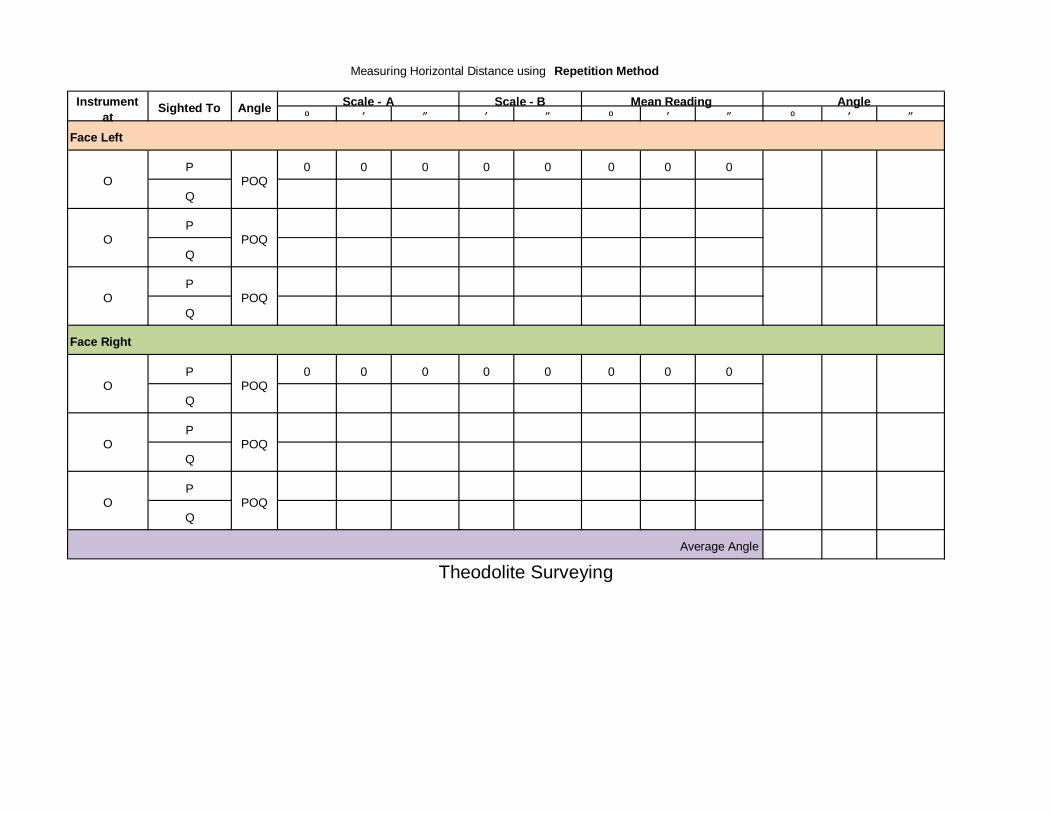
MEASUREMENT OF HORIZONTAL ANGLE BY REPETITION METHOD
OBJECTIVE:
To measure a horizontal angle by repetition method.
THEORY: In this method, the angle is added several times mechanically and the value of
the angle obtained by dividing the accumulated reading by the number of repetitions.
EQUIPMENTS USED:
• Transit Theodolite
• Tripod and
• Ranging rods
PROCEDURE:
1. Set up the instrument over ‘O’ and level it accurately.
2. With the help of upper clamp and tangent screw, set 0º reading on vernier ‘A’. Note the
reading of vernier ‘B’.
3. Release the upper clamp and direct the telescope approximately towards the point ‘P’.
Tighten the lower clamp and bisect point ‘P’ accurately by lower tangent screw.
4. Release the upper clamp and turn the instrument clock-wise towards Q. Clamp the upper
clamp and bisect ‘Q’ accurately with the upper tangent screw. Note the readings of
verniers ‘A’ and ‘B’ to get the values of the angle POQ.
5. Release the lower clamp and turn the telescope clockwise to sight P again. Bisect P by
using the lower tangent screw.
6. Release the upper clamp, turn the telescope clockwise and sight Q. Bisect Q by using
the upper tangent screw.
7. Repeat the process until the angle measured (required number of times is 3). The
average angle with face left will be equal to final reading divided by three.
pg. 8
8. Change face and make three more repetitions as described above. Find the average
angle with face right, by dividing the final reading by three.
9. The average horizontal angle is then obtained by taking the average of the two angles
with face left and face right.

pg. 9
Experiment No.: 3
MEASUREMENT OF HORIZONTAL ANGLE BY REITERATION METHOD
OBJECTIVE:
To measure horizontal angle by reiteration method.
EQUIPMENTS:
• Transit Theodolite
• Tripod and
• Ranging rods
PROCEDURE:
If it is required to measure angles AOB, BOC, and COD etc by reiteration method
The following steps are to be used.
1. Set the instrument over “O” and level it set the Vernier to zero and bisect point A
accurately.
2. Loose the upper clamp and turn the Telescope clockwise to point B. Bisect B by
using the upper tangent screw. Read both the Verniers, the mean of the Verniers will give
the angles AOB.
3. Similarly, bisect successively C, D etc, thus closing the circle. Read both the
Verniers at each bisection.
4. Finally sight to A the reading of the vernier should be the same as the original
setting reading.
Repeat the steps 02 to 04 with other face i.e. face Right.
pg. 10
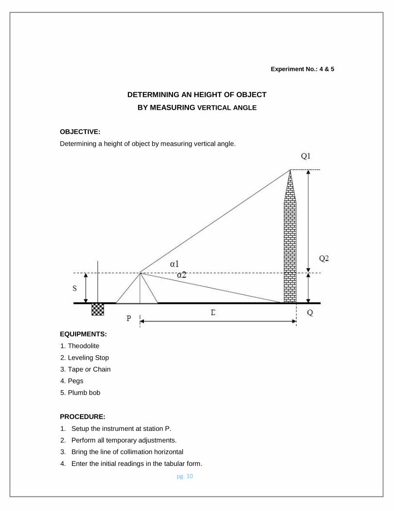
Experiment No.: 4 & 5
DETERMINING AN HEIGHT OF OBJECT
BY MEASURING VERTICAL ANGLE
OBJECTIVE:
Determining a height of object by measuring vertical angle.
EQUIPMENTS:
1. Theodolite
2. Leveling Stop
3. Tape or Chain
4. Pegs
5. Plumb bob
PROCEDURE:
1. Setup the instrument at station P.
2. Perform all temporary adjustments.
3. Bring the line of collimation horizontal
4. Enter the initial readings in the tabular form.

pg. 11
5. Swing the telescope and take staff reading over the given B.M.
6. Swing the telescope towards the object.
7. Release the vertical clamp screw, sight the top of the object Q1, and clamp the vertical
clamp screw.
8. Read C and D verniers and enter the readings.
9. Release the vertical clamp screw, sight the bottom of the object Q, and clamp the
screw.
10. Read vernier readings and enter in the tabular form.
11. Measure the Horizontal distance between the instrument station and the object.
12. The above procedure will be repeated with the face right observation.
13. The average of the two observations by transiting the telescope taken with different
faces will be vertical angle.
14. Calculate the height of the top point Q1 from horizontal line (h1) and height of the
bottom point Q0 from horizontal line (h2) by using formula h = d tan α
Methods:
1. Measurement of Height of an object when base is accessible (on level ground)
h = D tan α Height of the object = s + h R.L. of top of the object = R. L. of B.M.
+ s + h

pg. 12
2. Measurement of Height of an object when base is inaccessible

pg. 13
Experiment No.: 6
DETERMINATION OF CONSTANTS OF TACHEOMETER
OBJECTIVE
To determine the multiplying constant and additive constant of the given theodolite.
EQUIPMENTS
• Theodolite
• Ranging Rods
• Levelling Staff
• Tape
PROCEDURE
1. Stretch the chain in the field and drive pegs at 10m, 20m interval.
2. Set the theodolite at the zero and do the temporary adjustments.
3. Keep the staff on the pegs and observe the corresponding staff intercepts with horizontal
site.
4. Substitute the values of distance (D) and staff intercept (s) for different points in the
equation D = ks + C, where k & s are the tacheometric constants. k is the multiplying
constant & C is the additive constant.
5. Solve the successive pairs of equations to get the value of k & C and find out the
average of these values.

pg. 14
Measurement of Horizontal Distance
Instrument Station
Staff Station
Distance
Stadia Reading Stadia Intercept
(S) Top Middle Bottom
O
A
B
D = KS + C
D1 = K.S1 + C 1
D2 = K.S2 + C 2
Solve Two Equations & find K & C
RESULT:
Multiplying constant, K =
Additive constant, S =

pg. 15
Experiment No.: 7
MEASUREMENT OF HORIZONTAL DISTANCE & VERTICAL HEIGHTS USING
TACHEOMETRIC SURVEYING
OBJECTIVE:
Determination of elevation of points by Tacheometric surveying
EQUIPMENT:
• Tacheometer with tripod,
• Tape,
• Leveling staff,
• Ranging rods
THEORY:
The Tacheometer is an instrument which is generally used to determine the horizontal as
well as vertical distance . it can also be used to determine the elevation of various points
which cannot be determine by ordinary leveling. When one of the sight is horizontal and
staff held vertical then the RLs of staff station can be determined as we determine in
ordinary leveling .But if the staff station is below or above the line of collimation then the
elevation or depression of such point can be determined by calculating vertical distances
from instrument axis to the central hair reading and taking the angle of elevation or
depression made by line of sight to the instrument made by line of sight to the instrument
axis.
Procedure:
1) Set up the instrument in such a way that all the point should be visible from the
instrument station.
2) Carryout the temporary adjustment and set vernier zero reading making line of sight
horizontal.
3) Take the first staff reading on Benchmark and determine height of instrument.

pg. 16
4) Then sight the telescope towards the staff station whose R.Ls are to be calculated.
Measure the angle on vernier if line of sight is inclined upward or downward and also
note the three crosshair readings.
5) Determine the R.Ls of various points by calculating the vertical distance

pg. 17

pg. 18
Experiment No.: 8
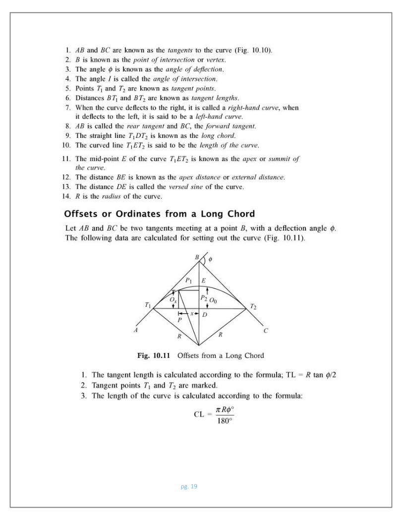
SIMPLE CURVE SETTING BY OFFSETS FROM LONG CHORD METHOD
OBJECTIVE:
To set out a simple curve by linear method (offsets from long chord method)
EQUIPMENT:
• Cross Staff,
• Arrows,
• Ranging rod
• Tape
THEORY:
Linear methods are used when:- 1. High
degree of accuracy is not required
2. The curve is short
Linear methods for setting out curve include
1. By ordinates or offsets from long chord.
2. By offsets from tangents (T)
a. Perpendicular offsets
b. Radial offsets
ELEMENTS OF SIMPLE CIRCULAR CURVE
pg. 19

pg. 20
Experiment No.: 9

pg. 21
SETTING OUT OF SIMPLE CIRCULAR CURVE BY RANKINE METHOD
OBJECTIVE:
Setting out of simple circular curve by Rankine method of tangential angle.
EQUIPMENT:
• Theodolite with Tripod
• Ranging rods
• Arrows
• Tape
Horizontal Curve Setting by Ranking Method

pg. 22
PROCEDURE:

pg. 23
1. Set the theodolite at the point of curve T1.
2. With both the plates clamped to zero, direct the theodolite to bisect the point of
intersection V. The line of sight is thus in the direction of the rear tangent.
3. Release the vernier plate and set angle 1 on the vernier .The line of sight is thus directed
along chord T1A.
4. With zero end of tape pointed at T1 and arrow held at a distance T1A = c along it, swing
the tape around T1 till the arrow is bisected by the cross hairs.
5. Thus the first point A is fixed.
6. Set the second deflection angle 2 on the vernier so that the line of sight is directed along
T1B.
7. With the zero end of the tape pinned at A, and an arrow held at distance AB = C along it,
swing the tape around A till the arrow is bisected by the cross hairs, thus fixing the point
B.
8. Repeat steps 4 and 5 till last point is reached.

pg. 24

1
TOTAL STATION
1. PREPARATION
1.1 Precautions
1. Never point the instrument at the sun without
a filter.
2. Never store the instrument in extreme
temperatures and avoid
sudden changes of temperature.
3. When not using the instrument, place it in the
case to avoid
shock, dust, and humidity.
4. If thereis a greatdifferencein
temperaturebetweenthe work site and the instrument
storage location leave the instrument in the
case until it adjusts to the temperature of the surrounding
environment.
5.Pleaseremovethebatteryforseparatestorageiftheinstrument
istobeinstorageforanextendedtime.Thebatteryshouldbecharged
once a month during storage.
6. The instrument should be placed in its
carrying case during transportation. It is recommended that
the original packing case be
used for cushioning during extended transportation.
7. Be sure to secure the instrument with one hand
when mounting
2
or removing from the tripod.
8.Cleanexposedopticalpartswithdegreasedcottonorlenstissue
only.
9.Cleantheinstrument'ssurfacewithawoolenclothwhenfinished with
use. Dry it immediately if it gets wet.
10. Check the battery, functions, and indications
of the
instrument as well as its initial setting and correction parameters
before operating.
11. Unless you are a maintenance specialist do not
attempt to disassemble the instrument for any reason.
Unauthorized disassembly
of the instrument can result in a void warranty.
12. Thetotalstationsemitalaserduringoperation.DONO
Tstare into the beam or laser source when instrument is
operation.

3
1.2 Nomenclature

4
1.3 Unpacking and Storage of the Instrument
Unpacking of the Instrument
Place the caselightly withthe cover upward,unlock the case and
take out the instrument.
Storage of the Instrument
Replacethecoveronthetelescopelens,placetheinstrumentinto the
case with the vertical clamp screw and circular vial upward

5
(objectivelenstowardthetribrach),tightentheverticalclampscrew, close
and lock the case.
1.4 Instrument Set Up
Mounttheinstrumentontothetripod andsecurefirmly.Leveland center
the instrument precisely to ensure the best performance. Use
the tripod with a 5/8” tripod screw.
Operation Reference: Leveling and Centering the Instrument
1). Setting up the tripod
Firstextendtheextensionlegstosuitablelengthandtightenthe
screws, firmly plant the tripod in the ground over the point of
beginning.
2). Attaching the instrument to the tripod
Secure the instrument carefully on the tripod and slide the
instrumentbylooseningthetripodmountingscrew.Iftheopticalplumb site
is positioned over the center of the point tighten the mounting
screw.
3). Roughly leveling the instrument by using the circular vial
TurnthelevelingscrewA and Bto movethebubblein thecircular vial,
in which case the bubble is located on a line perpendicular to a
line running through the centers of the two leveling screw being
adjusted. Turn the leveling screw C to move the bubble to the
center of the circular vial.Recheckthe positionof the
instrumentover the
point and adjust if needed.
4). Leveling by using the plate vial

6
Rotate the instrument horizontally by loosening the Horizontal
ClampScrewandplacetheplatevialparallelwiththelineconnecting
leveling screws A and B, then bring the bubble to the center of the
plate vial by turning the leveling screws A and B.
Rotate the instrument 90° (100g) around its vertical axis and
turn the remaining leveling screw or leveling C to center the
bubble
once more.
Repeat the procedures for each 90° (100g) rotation of the
instrument and check whether the bubble is correctly centered in
all
directions.
5). Centering by using the optical plummet(or laser plumment)
Adjust the eyepiece of the optical plummet telescope to your
eyesight. Slide the instrument by loosening the tripod screw; place
the point on the center mark of the optical plummet. Sliding the
instrument carefully as to not rotate the axis will allow you to
get the least dislocation of the bubble.(Place star-key after power
on, thenpressF4(LASER)key,pressF1(ON)keytoturnonthelaserplumment.
Slidetheinstrumentbylooseningthetripodscrew;Placelaserfacular on
the occupied pointing, Sliding the instrument carefully as to not
rotate the axis will allow you to get the least dislocation of the
bubble. The last, press ESC key, and laser plummet turn off
automatically.)
6). Complete leveling the instrument

7
LeveltheinstrumentpreciselyasinStep4.Rotatetheinstrument and
check to see that the bubble is in the center of the plate level
regardless of the telescope direction then tighten the tripod screw
firmly.
1.5 Battery Removal & Insertion - Information and Recharging
Battery removal & insertion
Insertthebatteryintothebatteryslotandpushthebatteryuntil
it clicks.
Press the right and left buttons of the battery compartment to
remove the battery.
Battery information
------------- Indicates that battery is fully
charged
-------------Indicatesthatthebatterycanonlybe used
for about 1 hour.
Recharge the battery or prepare a recharged
battery for use.
-------------Rechargethebatteryorpreparearecharged
battery for use.

8
Note:Theworkingtimeofthebatteryisdeterminedbyenvironment
conditions, recharging time, and other factors.
Battery Recharging
Battery should be recharged only with the charger supplied with
the instrument.
Remove the on-board battery from instrument as instructed and
connect to the battery charger.
Battery Removal Caution
▲Beforeyoutakethebatteryoutoftheinstrument,makesurethat the
power is turned off. Otherwise the instrument can be damaged.
Recharging Caution:
▲ The charger has built-in circuitry for protection from
overcharging.However,donotleavethechargerpluggedintothepower outlet
after recharging is completed.
▲Be sure to recharge the battery at a temperature of 0℃~45
℃, recharging may be abnormal beyond the specified temperature
range.
▲When the indicator lamp does not light after connecting the
battery and charger the battery or the charger may be damaged.
Storage Caution:
▲The rechargeable battery can be repeatedly recharged 300-500
times.Completedischargeofthebatterymayshortenitsservicelife.
▲In ordertogetthemaximumservicelifebe suretorechargethe
battery at least once a month.

9
1.6 Reflector Prisms
When doing distance measuring in prism mode a reflector prism
needs to be placed as the target. Reflector systems can be single
or multipleprisms which canbe mountedwith a tripod/tribrachsystem
or mounted on a prism pole. Unique mini prism systems allow setups
at cornersthatarehardtoreach.Reflectorlesstargetsextendtherange
of the instrument when used in reflectorless mode.
Illustrated are some prisms and a reflector compatible with
instruments:

10
1.7MountingandDismountingtheInstrumentfromthe
Tribrach
Dismounting
Whennecessarytheinstrumentcanbedismountedfromthetribrach.
Loosen the tribrach locking screw in the locking knob with a
screwdriver if necessary. Turn the locking knob 180 degrees
counter-clockwise to disengage anchor jaws and remove the
instrument from the tribrach.
Mounting
Insert three anchor jaws into holes in tribrach and line up the
directing stub on the instrument with the directing slot of the
tribrach. Turnthe lockingknob180 degreesclockwiseand tightenthe
locking screw with a screwdriver.
11
1.8 Eyepiece Adjustment and Object Sighting
Method of Object Sighting (for reference)
Sightthetelescopetotheskyandrotatetheeyepiecetubetomake
the reticule clear.
Collimate the target point with top of the triangle mark in the
collimator. (keepacertaindistancebetweeneyeandthecollimator). Make
the target image clear with the telescope focusing screw.
If there is parallax when your eye moves up and down or left
and right this indicatesthe diopterof the eyepiecelens or focus is
not adjusted well and accuracy will be effected. You should
readjust the eyepiece tube carefully to eliminate the parallax.
1.9 Turning the instrument On and Off
Power on
1. Be sure that the instrument is leveled.
2. Press and momentarily hold the power (POWER) key.
3. Rotate the EDM head in an upwards direction to initialize.
4.ToturnOFFpressandholdthepowerkeyuntilinstrumentpowers
down.
Be sure there is sufficient battery power. If 'Battery Empty'
is shown on the display, the battery should be recharged or
replaced.
***DONOTremovethebatteryduringmeasuring,otherwisethedatawill be
lost and the instrument could be harmed!! ***

12
1.10 How To Enter Alphanumeric Characters
*How to select an item
[Example 1] Select INS.HT (instrument height) in the data
collectionmode (firstpressthe MENUbutton thenF1:DATACOLLECTand then
select the data file desired. Press F2 to list, the arrow keys to
choose and then F4 to select). Press F1 again for OCC.PT# INPUT.
The arrow(→) indicates an item to enter. Press[▲] [▼] key to
move the arrow line up or down
Press [▼] move->R..HT
Press F1 INPUT then 1 to input“1”
Press . to input “. ”
Press 5 to input “5 ”, press ENT
Then R. HT =1.5 m *How to enter characters
[Example 2] Input the code “ABC1”of instrument point in Data
Collection Mode.
1.Move the arrow to PCODE using the [▲]or [▼]key

13
Press [7] key once for “A”
Press [7] key twice for “B”
Press [7] key three times for “C”
Press[1]keyoncefor “1”(*PressF3toswitchtoNUMBmodefirst) Press
enter key to finish input
2. FUNCTION KEY AND DISPLAY
2.1 Operating Key

14
key)
0- 9 Number key Input numbers
Keys Names Function
ANG Angle meas. key Angle measurement mode
Distance meas. key Distance measurement mode
Coordinate meas.
key Coordinate measurement mode ( Up)
S.O Layout key Layout measurement mode ( Down)
K1 Quick key1 User-defined quick key 1( Left)
K2 Quick key 2 User-defined quick key 2( Right)
ESC Escape key Return to the measurement mode or
previous layer mode.
ENT Enter key Press after confirmation of
inputting values
M Menu key Switches menu mode and normal mode
T Shift key Shift distance measuring key
Star key Press once to adjust contrast or
twice for illumination of keypad
Power key On / Off key press and hold
F1 - F4 Soft key ( Function Responds to the message displayed

15
— Minus key Input minus sign, displays
electronic bubble
. Point key On / Off laser pointing function
Display marks:
Display Content
V Vertical angle
V% Vertical angle
display) as a percentage (Gradient
HR Horizontal angle (right)
HL Horizontal angle (left)
HD Horizontal distance
VD Elevation difference
SD Slope distance
N North coordinate
E East coordinate
Z Z or elevation coordinate
* EDM working
m/ft Switches units between meters and feet
m Meter unit
S/A Sets temperature,air pressure, prismconstant
PSM Prism constant (unit:mm)
PPM Atmospheric correction
2.2 Function Key
Angle measurement mode (three-page menu)

16
Page Ke ys Display
marks Function
P1 F1 0SET Horizontal angle is set to 0°0′0″
F2 HOLD Hold the horizontal angle
F3 HSET Setarequiredhorizontalanglebyentering
numbers
F4 P1↓ Scroll to the next page (P2)
P2
F1
TILT
Tilt correction screen. If the correction
is turnedon thedisplaywillshowthetilt
correction value.
F2
F3 V% Vertical angle percent grade (%) mode
F4 P2↓ Scroll to the next page (P3)
P3 F1 R/L SwitchesRight/Leftrotationofhorizontal
angle
F2
F3 CMPS Switches vertical angle “0” position
F4 P3↓ Scroll to the next page (P1)
Distance measurement mode (two-page menu)

17
Page Ke ys Display marks Function
P1 F1 MEAS Begin measuring
F2 MODE Sets measuring mode,
Fine/--/Tracking
F3 S/A Sets temperature, air pressure,
prism constant
F4 P1↓ Scroll to the next page (P2)
P2 F1 OFSET Selects Off-set measurement mode
F
2 S.O. Selects Stake Out measurement mode
F3 m / ft Switches units between meters and
feet
F4 P2↓ Scroll to the next page (P1)
Coordinate measurement mode(three-page menu)

18
P3 F1 OFSET Off-set measurement mode
F2 BACKSIGHT Setting a direction angle for
backsight orientation
F3 m / ft Switches meter and feet unit.
F4 P3↓ Shows the function of soft keys on
page1
2.3 star-key mode
The total station(non-reflectorless):
Press the star key , following is displayed:

19
1.Contratadjustment:Afterpressingstarkey,adjustthedisplay
contrast by pressing [▲] or [▼] key.
2. Illumination: After pressing star key, select
[Illumination]
by pressing F1(LAMP) key or press star key.
3. Tilt: After pressing star key, select [tilt] by pressing
F2
(TILT) key, and select ON or OFF by pressing F1 or F3 key, press F4
(ENT) key.
4.S/A:Afterpressingstarkey,select[S/A]bypressingF3(S/A) key,
then you can set Prism contrast, air pressure and temperature.
5. Laser plumment: If total station has this function, after
pressingstarkey,select[laser]bypressingF4(LASR)key,andselect ON or
OFF by pressing F1 or F2 key.
*In some interface, you can turn on or turn off panel backlight
by press star key directly.
The total station(reflectorless):
Press the star key , following is displayed:

20
1.Mode: Press the F1 (mode) key, the following is displayed :
You can select the type of measure mode by pressing the F1—F3
keys.
2.You can turn on the lampby pressing the starkey once more or
by pressing twice from any menu.
2.4 Dot-key Mode
The total station can function as a laser pointer
The laser pointer can be turned on or off by pressing the (.)
dot key.
21
3. INITIAL SETTINGS
The series total station can be reset to the instruments
original factory settings.
See Section 11 “Basic Settings”
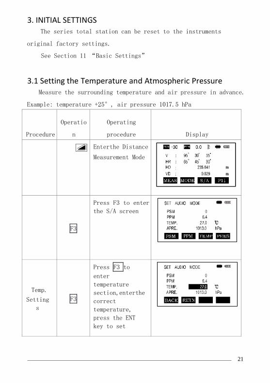
3.1 Setting the Temperature and Atmospheric Pressure
Measure the surrounding temperature and air pressure in advance.
Example: temperature +25°, air pressure 1017.5 hPa
Procedure
Operatio
n
Operating
procedure Display
Enterthe Distance
Measurement Mode
F3
Press F3 to enter
the S/A screen
Temp.
Setting
s
F3
Press F3 to
enter
temperature
section,enterthe
correct
temperature,
press the ENT
key to set
22
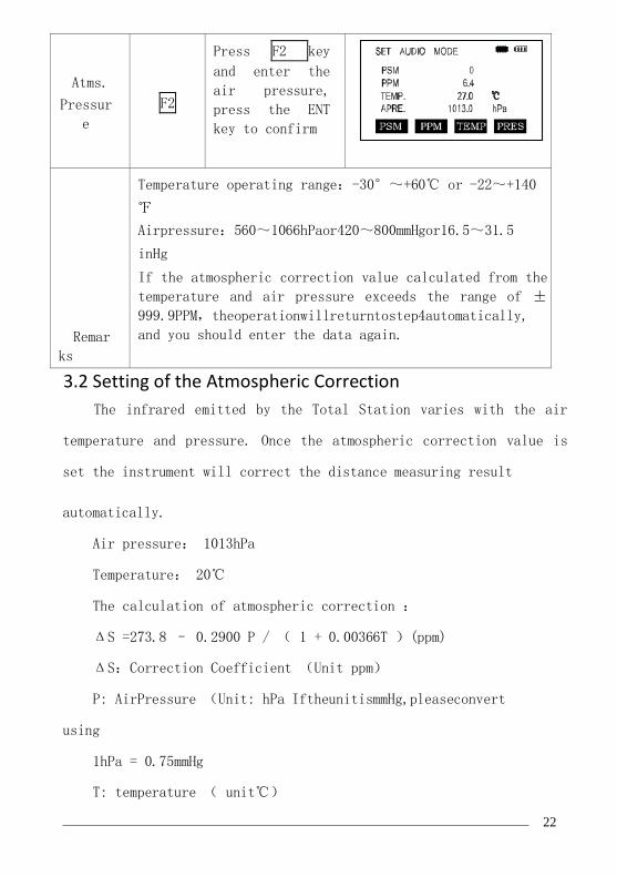
Atms.
Pressur
e
F2
Press F2 key
and enter the
air pressure,
press the ENT
key to confirm
Remar
ks
Temperature operating range:-30°~+60℃ or -22~+140
℉
Airpressure:560~1066hPaor420~800mmHgor16.5~31.5
inHg
If the atmospheric correction value calculated from the
temperature and air pressure exceeds the range of ±
999.9PPM,theoperationwillreturntostep4automatically,
and you should enter the data again.
3.2 Setting of the Atmospheric Correction
The infrared emitted by the Total Station varies with the air
temperature and pressure. Once the atmospheric correction value is
set the instrument will correct the distance measuring result
automatically.
Air pressure: 1013hPa
Temperature: 20℃
The calculation of atmospheric correction :
ΔS =273.8 – 0.2900 P / ( 1 + 0.00366T )(ppm)
ΔS:Correction Coefficient (Unit ppm)
P: AirPressure (Unit: hPa IftheunitismmHg,pleaseconvert
using
1hPa = 0.75mmHg
T: temperature ( unit℃)

23
Direct Setting Method of Atmosphere Correction Value
After measuring the temperature and air pressure the atmosphere
correction value can be obtained from an atmospheric correction
chart or correction formula (PPM).
Procedur
e Operatio
n Operation Procedure Display
F3 Press F3 Key in
distance
measurement or
coordinate
measurement
mode
F2
Press F2 [ppm] key
, which shows the
current setting
value
Enter
value
Enter atmospheric
correctionandpress
ENT
*1)See 2.10“How to Enter Alphanumeric Characters”
Input range:-999. 9PPM to +999. 9 Step length: 0 .1PPM *2)If
Temperature and Atmospheric Pressureare reset,the PPM will be
recalculated automatically.
3.3 Setting of the Prism Constant
In the factory the prism constant for the total station is set
at -30mm. Ifthe constantof theprismusedis not-30mm,you mustchange

24
this setting. Once the prism constant is set it will become the new
default value until changed.
Procedur
e
Operatio
n
Operation
Procedure
Display
F3
PressF3(S/A)Key
in Distance
Measurement Mode
or Coord.
Measurement Mode.
② F1 ② PressF1(PRISM
) key
③ Enter
data
Press F1 (INPUT)
key to enter the
Prism Constant
correction value.
*1, press F4 to
confirm and return
to the Setting
Mode.
Input range:-99. 9mm to +99. 9mm Step length 0. 1mm
*The total station in reflectorless measuring mode sets the prism
constant to 0 automatically.
25
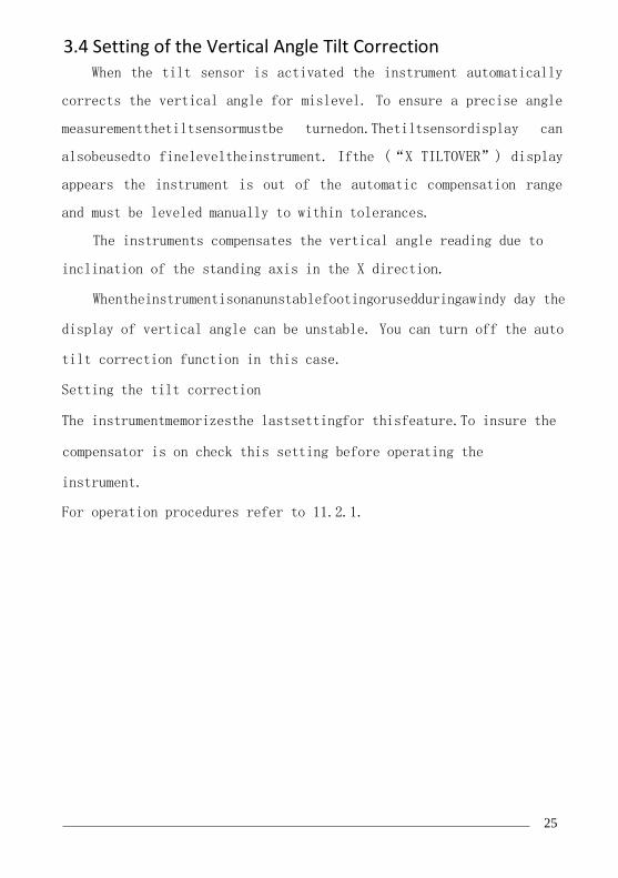
3.4 Setting of the Vertical Angle Tilt Correction When the tilt sensor is activated the instrument automatically
corrects the vertical angle for mislevel. To ensure a precise angle
measurementthetiltsensormustbe turnedon.Thetiltsensordisplay can
alsobeusedto fineleveltheinstrument. Ifthe (“X TILTOVER”) display
appears the instrument is out of the automatic compensation range
and must be leveled manually to within tolerances.
The instruments compensates the vertical angle reading due to
inclination of the standing axis in the X direction.
Whentheinstrumentisonanunstablefootingorusedduringawindy day the
display of vertical angle can be unstable. You can turn off the auto
tilt correction function in this case.
Setting the tilt correction
The instrumentmemorizesthe lastsettingfor thisfeature.To insure the
compensator is on check this setting before operating the
instrument.
For operation procedures refer to 11.2.1.

26
4.ANGLE MEASUREMENT
4.1 Measuring Horizontal Angle Right and Vertical Angles
Make sure the angle measurement mode is selected.
Operation procedure Operation Display
①Collimate the first
target (A) Collimate A
Tosethorizontalangle
of target A at 0º
00’00" press the F1
(0SET) key and then
press the F4 (YES) key
F1
F4
③Collimate the second
target (B)
The required V/H angle
to target B will be
displayed Collimate B
Note : The horizon anglewill be savedwhen the instrument is powered
off and displayed when powered on.

27
Reference: How to Collimate Point the telescope toward a light surface or sky. Turn the diopter
ring and adjust the diopter so that the cross hairs are clearly
observed.
Aim the target at the peak of the triangle mark of the sighting
collimator. Allowa certainspacebetweenthesightingcollimatorand
yourself for collimating.
Focus the target with the focusing knob.
If parallax is created between the cross hairs and the target when
viewing vertically or horizontally while looking into the
telescope, focusing is incorrect or diopter adjustment is poor.
This adversely affects precision in measurement please eliminate
the parallax by carefully focusing and using the diopter
adjustment.

28
4.2 Switching Horizontal Angle Right/Left
Make sure the angle measurement mode is selected.
Operation procedure Operatio
n
Display
Pressthe F4 Keytwicetoget
the menu to page 3. (P3)
F4
twice
Press the F1(R/L)key. The
Horizontal Right angle
mode (HR) Switches to
Horizontal Left mode (HL) F1
Measure as HL mode
*Each time the F2 (R/L) key is pressed the HR/HL mode switches
4.3 Setting of the Horizontal Angle
4.3.1 Setting by Holding the Angle
Make sure the angle measurement mode is selected.
Operation procedure Operatio
n
Display

29
① Set the required
horizontalangleusingthe
horizontal tangent screw
Display
angle
②Press the F2 (HOLD)key F2
③Collimate the target
Collimat
e
④Press the
to finish
horizontal
display turn
normal angle
measurement
F4 (YES) key
holding the
angle, the
s back to the
mode F4
*To return to the previous mode, press the ESC key.
4.3.2 Setting the Horizontal Angle from the Keypad

30
Make sure the angle measurement mode is selected.
Operation procedure Operatio
n
Display
①Collimate the target
Collimat
e
②Press the F3 (HSET)
key
F3
③ Input the
horizontal angle
the keys, for
150.10.20, inputs
150º10′20″.
Press ENT
Carry on
measurement
entering the
horizontal angle
required
by using
example:
normal
after
required
150.10.2
0
ENT

31
Make sure the angle measurement mode is selected.
Operation procedure Operatio
n
Display
Press F4 key to get
the function on menu
page P2
F4
Press the F3 ( V% ) key
* F3

5. DISTANCE MEASUREMENT
When setting the atmospheric correction obtain the correction
value by measuring the temperature and pressure.
5.1 Setting of the Atmospheric Correction
When setting the atmospheric correction obtain the correction
valueby measuring thetemperature and pressure.Referto Section3.2
“Setting of the Atmospheric Correction”.
Operation procedure Operatio
n
Display
Press F4 key twice to get the
menu on page 3 ( P 3) :
F4
twice
Press the F3 ( CMPS ) key * F3
* Each time the F3 key is pressed the display mode switches.

5.2 Setting of the Correction for Prism Constant 343435
The instrument is preset for a Prism Constant value of -30mm at
the factory.If the prismis of anotherconstantthe instrumentneeds to
be updated with this constant. Refer to Chapter 3.3 “Setting of
thePrismConstant”.Theupdatedvalueiskeptintheinstrumentmemory after
the power is shut off.
5.3 Distance Measurement (Continuous Measurement) Make
sure the angle measurement mode is selected.

3635 *1)The total station prism mode collimate center of prism when
measuring;
*2)WhenEDM is working,the “*” markappearsin thedisplay.The
total stations will display “weak signal” when measuring if the
signal is weak.
*3)To change the mode from Fine to Tracking, refer to section 5.4
“Fine mode / Tracking Mode”. To set the distance measurement on
when the instrument is powered up, refer to Chapter 11 “Basic
Settings”.

*4)Thedistanceunitindicator"m"(formeter)or “ft” (forfeet)
appearsanddisappearsalternativelywithabuzzersoundingatevery
renewal of distance data.
*5) Measurement may repeat automatically in the instrument if the
result is affected by external factors*.
*6 ) To return to the angle measuring angle mode from the
distance-measuring mode, press the ANG key.
*7)Itispossibletochoosethedisplayorder(HR,HD,VD)or(V,HR,SD) for
initial measuring mode. Refer to Chapter 11 "Basic Settings".
5.4 Changing the Distance Measurement Mode
(Repeat Measurement / Single Measurement/ Track
Measurement)
Make sure the angle measurement mode is selected.
Operation procedure Operatio
n Display
37

5.5 Stake Out (S.O.)
38
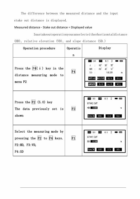
The difference between the measured distance and the input
stake out distance is displayed.
Measured distance - Stake out distance = Displayed value
Inastakeoutoperationyoucanselecteitherhorizontaldistance
(HD), relative elevation (VD), and slope distance (SD.)

39
Enterthedistance350, press
F4
Enter
350
F4
Collimate the target
(Prism), measurement starts.
The difference between the
measured distance and the
stake out distance is
displayed.
Collimat
e
Pris
m
Move the target until the
difference becomes 0.
To return to normaldistancemeasurement mode,stake out distance to
“0” or switch to other measurement mode.
5.6 Offset Measurement
There are four offset measurement modes:
40

52
*1)To return to procedure 5, press F4 (NEXT) key
*2)Toescapethemeasuring,pressESCkey,thedisplayreturnstothe
previous mode.
6. COORDINATE MEASUREMENT
6.1 Execution of Coordinate Measurement
Measure the coordinates by entering the instrument height and
prismheight,coordinatesofunknownPointwillbe measureddirectly.
* When setting coordinate values of occupied point, see
Section 6.2 “Setting Coordinate Values of Occupied Station
Point”.
*Whensettingtheinstrumentheightandprismheight,seeSection 6.3
“SettingHeight of the Instrument” and 6.4 “SettingHeight of
Target (prism Height)”.
* To set backsight, determine the backsight azimuth or
check the known azimuth, coordinate and distance.
Thecoordinatesoftheunknownpointarecalculatedasshownbelowand
displayed:
Coordinates of occupied point:(N0,E0,Z0)
To show the coordinate
of point P0 , press
key. *1*2

53
Instrument height :INS.HT
Prism height: R.HT
Vertical distance (Relative elevation):Z(VD)
Coordinatesofthecenteroftheprism,originatedfromthecenter point
of the instrument:(n,e,z)
Coordinates of unknown point:(N1,E1,Z1)
N1=N0+n
E1=E0+e
Z1=Z0+INS.HT+Z-R.HT
Center point of the instrument (N0, E0, Z0+INS.HT)
When doing coordinate measurement coordinates of occupied point,
the instrument height, the prism height and back sight azimuth
should be
set.

54
6.2 Setting Coordinate Values of Occupied Point
Set the coordinates of the instrument (occupied point)
according
toknownvaluesandtheinstrumentautomaticallyconvertsanddisplays
theunknownpoint(prismpoint)coordinatesfollowingtheobservation.
Theinstrumentretainsthecoordinatesoftheoccupiedpointafter
turning the power off.

55
Operation procedure Operatio
n
Display
Press the F4 (P1↓) key
from the coordinate
measurement
modetogetthefunctionon
menu P2.
F4
Press the F3(OCC)key F3
③EnterN coordinatevalue
Enter
data
ENT

56
④EnterE and Z coordinate
values in the same
manner. After entering
the
values, the display
returns to the coordinate
measuring display menu.
Enter
data
ENT
Input range:-999999.999m/ft ≤ N、E、Z ≤ +999999.999m/ft
6.3 Setting Height of the Instrument
The instrument height value will be retained after the instrument
is powered off.
Operation procedure Operatio
n
Display
Press the F4 (P1
the coordinate
mode to access
screen.
↓) key from
measurement
the P2 menu
F4

57
② Press the F2
The current
displayed.
(I.HT) key,
value is
F2
Enter the instrument height
andpressthe ENT keyto get
to the coordinate
measuring display
Enter
the I.H.
ENT
Input range:
—999.999≤INS.HT≤+999.999m
6.4 Setting Height of Target (Prism Height)
This mode can be used to obtain z coordinate values. The target
height value will be retained after the instrument is powered off.
Operation procedure Operatio
n
Display

58
Pressthe F4 (P1↓) key from
the coordinate measurement
mode
toaccesstheP2menuscreen.
F4
②Press the F1 (R.HT) key
The current value is
displayed. F1
Enter the prism height,
then
pressthe ENT key to get
to the coordinate measuring
display
Enter
the
prism
height
ENT
Input range:
—999.999m≤prism height≤+999.999m/ft
7. SURVEYING PROGRAM Surveying
Program Mode (programs)
By pressing the menu key M , the instrument will be in Menu Mode.
59
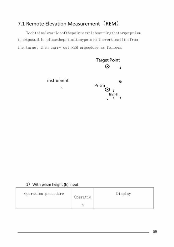
7.1 Remote Elevation Measurement(REM)
Toobtainelevationofthepointatwhichsettingthetargetprism
isnotpossible,placetheprismatanypointontheverticallinefrom
the target then carry out REM procedure as follows.
1)With prism height (h) input
Operation procedure Operatio
n
Display

60

61
⑥Collimate prism
Collimat
e Prism
⑦PresstheF1(MEAS)key,
measurement starts.
Horizontal distance (HD)
betweentheinstrumentand
prism will be shown. F1
⑧Press the F4 (SET)
Theprismpositionwillbe
decided. F4
⑨ Collimate target K.
Vertical distance
(VD) will be shown.
Collimat
e K
To return to procedure 5,press F2 (R.HT) key.
To return to procedure 6,press F3 (HD) key.
To return to PROGRAMS Menu, press the ESC key.

62
2)Without prism height input
Operation procedure Operatio
n
Display
Press the M menu key M
PresstheF2key,enterthe
measure programs menu. F2
③Press the F1 (REM) Key. F1
④ Press the F2 key to
select the mode without
prism height. F2

63
Collimateprism,pressthe
F1 (MEAS) key. Measuring
starts. Horizontal
distance (HD) between the
instrumentandtargetwill Collimat
e target
be shown..
⑥Press the F4 (SET)
Thetargetpositionwillbe
decided. F4
Collimate ground pointG ,
presstheF4(SET)key.The
position of point G will
be decided
F4
Collimate target K
Vertical distance (VD)
will be shown Collimat
e K
To return to procedure 5, press the F3 (HD) key.
To return to procedure 6, press the F2 (V) key.
To return to PROGRAMS Menu, press the ESC key.

64
7.2 Missing Line Measurement (MLM)
Measurement for horizontal distance (dHD) , slope distance
(dVD),elevation (dVR) and horizontal bearing (HR) between two
target
prisms.
Itispossibletoenterthecoordinatevaluedirectlyorcalculate
from coordinate data file.
MLM Mode has two modes:
1. MLM-1 (A-B, A-C): Measurement A-B, A-C, A-D
2. MLM-2 (A-B, B-C): Measurement A-B, B-C, C-D
It is necessary to set the direction angle of the instrument.
[Example] MLM-1 (A-B, A-C)
ProcedureofMLM-2(A-B,B-C)modeiscompletelythesameasthat of
MLM-1 mode.

65
Operation procedure Operatio
n
Display
①Press the M menu key
M
②Press the F2 key, enter
MEAS PROGRAMS F2
③Press the F2 (MLM) key F2
④Enter file name
Enter
file
name

66
⑤Press ENT key. ENT
⑥Press the F1 key F1
⑦Collimate prism A, and
press the F1 (MEAS) key.
Horizontal distance (HD)
between the instrument
and target A will be
shown.
Collimat
e A
F1
⑧Press the F4 (SET) key
The position of the
target is confirmed. F4

67
⑨Collimate prism B and
press the F1 (MEAS) key.
Horizontal distance (HD)
between the instrument
and target B will be
shown..
Collimat
e B
F1
⑩Press the F4 (SET) key
The horizontal
distance(dHD)andrelative
elevation (dVD) between
target A and B. F4
⑾To measure the distance
between points
AandC,presstheF4(NEXT)
key*1) F4
⑿ Collimate point C
(targetC)andpresstheF1
(MEAS) key.
Horizontal distance (HD)
between the instrument
and target C will be
shown.
Collimat
e C
F1

68
⒀Press the F4 (SET) key.
The horizontal distance
(dHD) and relative
elevation (dvD) between
tagetA andCwillbeshown
F4
⒁To measure the distance
between points
A and D, repeat procedure
12 to 14 *
*To return to Previous mode , press the ESC key.
HOW TO USE COORDINATE DATA
It is possible to input coordinate values directly or calculate
from a coordinate data file.
[Example] Input the data (NEZ) directly:
Operation procedure Operatio
n
Display

69
①Press the F3(NEZ) key F3
② Press the
F4(coordinate) key F4
③Entercoordinate,press
ENT key to get to the
second point.
ENT
*To return to PROGRAMS Menu, press the ESC key.
7.3 Area Calculation
This mode calculates the area of an enclosed figure.
There are two area calculation methods as follows:
1) Area calculation from Coordinate data file

70
2) Area calculation from measured data
Note:
Areaisnotcalculatedcorrectlyifobservedlinescrosseachother.
It is not possible to calculate area from a mix of coordinate
file data and measured data.
The number of points used for calculation is not limited.
The area to be calculated shall not exceed 200000 sqm. (approx.
49
acres)
1) Area calculation from Coordinate data file
Operation procedure Operatio
n
Display
①Press M menu key M
②Press the F2 key,
enter
the Measurement Program. F2

71
③Press F3 (AREA) key F3
Press F1 (FILE DATA) key F1
Enter file name or press
F2 for LIST. Press ENT
key, Initial displaywill
be shown .
Enter
File
name
ENT
⑥Press F4 (NEXT) key
The top of the file data
(DATA-01) will be set and
the second point number
F4
will be shown.

72
Repeatpressing F4 (NEXT)
keytosetrequirednumber
of the points. When 3
points are set, the area
surrounded by the points
is calculated and the
result will be shown.
F4
* To set the required point number, press F1 (PT#) key.
*Toshowthelistofthecoordinatedatainthefile,pressF2 (LIST)
key.
2) Area calculation from measured data
Operation procedure Operation Display
①Press M menu key M
②Press the F2 key, enter
the Measurement Program. F2

73
③Press F3 (AREA) key F3
Pressthe F2 (MEASUREMENT)
key
F2
Collimateatargetorprism
and press the F1 (MEAS)
key. Measuring starts *
Collimate
Prism
F1
Press the F4 key to
affirm F4
⑦Collimate a next prism
and press F1 (MEAS) key.
When 3 points are set,
the area surrounded by
the points is calculated
and the result will be
shown.
Collimate
F1

74
*1 Measurement is N-time measurement mode.

T
h
e
o
d
o
l
i
t
e
S
u
r
v
e
y
i
n
g
⁰ ’ ”
Main Scale 30 40
Vernier Scale
17 40
Reading 30 57 40
40 minutes 40 seconds
Theodolite Surveying
⁰ ⁰ ⁰
0 0 0 0 0 0 0 0 P
Q
P
Q
P
Q
0 0 0 0 0 0 P 0 0
Q
P
Q
P
Q O POQ
POQ O
Average Angle
Measuring Horizontal Distance using Repetition Method
A Scale - Scale - B Mean Reading Angle Instrument at
Angle Sighted To
Face Left
Face Right
POQ O
O POQ
O POQ
POQ O


Theodolite Surveying
Measurement of Height of an object when base is accessible
Instrument at Reading on B.M. Face Sighted To Angle
Scale - C Scale - D Angle Average Angle
⁰ ’ ” ’ ” ⁰ ’ ” ⁰ ’ ”
P
Face Left Q α1
Face Right Q α1
Measurement of Height of an object when base is inaccessible
Instrument at Reading on B.M. Face Sighted To Angle
Scale - C Scale - D Angle Average Angle
⁰ ’ ” ’ ” ⁰ ’ ” ⁰ ’ ”
P
Face Left Q α1
Face Right Q α1
R
Face Left Q α2
Face Right Q α2
