roller - robinsons hardware - best hardware stores by a ... sliding, falling or tipping. 2.1.7...
TRANSCRIPT

www.wackergroup.com
Roller
RD 11 /...
OPERATOR’S MANUAL
0155952en 004
0605
0 1 5 5 9 5 2 E N


RD 11 /... Table of Contents
wc_bo0155952003enTOC.fm 1
1. Foreword 4
2. Safety Information 5
2.1 Operating Safety .................................................................................. 62.2 Operator Safety while using Internal Combustion Engines .................. 72.3 Service Safety ...................................................................................... 82.4 Label Locations .................................................................................... 92.5 Safety Labels ...................................................................................... 102.6 Operating Labels ................................................................................ 11
3. Technical Data 15
3.1 Engine ................................................................................................ 153.2 Roller .................................................................................................. 163.3 Lubrication .......................................................................................... 163.4 Dimensions ......................................................................................... 173.5 Sound and Vibration Measurements .................................................. 17
4. Operation 18
4.1 Operation and Service Locations ....................................................... 184.2 Application .......................................................................................... 204.3 Recommended Fuel ........................................................................... 204.4 Before Starting ................................................................................... 204.5 Starting (RD11A / RD11V) ................................................................. 214.6 Stopping/Parking (RD11A / RD11V) .................................................. 224.7 Direction and Speed (RD11A / RD11V) ............................................. 234.8 Braking Machine (RD11A / RD11V) ................................................... 234.9 Starting (RD11AEC) ........................................................................... 244.10 Stopping/Parking (RD11AEC) ............................................................ 254.11 Direction and Speed (RD11AEC) ....................................................... 264.12 Braking Machine (RD11AEC) ............................................................. 274.13 Vibration (RD11A / RD11V) ................................................................ 284.14 Vibration (RD11AEC) ......................................................................... 294.15 Watering System ................................................................................ 304.16 Articulation Joint Lockarm .................................................................. 304.17 Adding Ballast to Rear Drum .............................................................. 31

Table of Contents RD 11 /...
wc_bo0155952003enTOC.fm 2
4.18 Roll Over Protection Structure (ROPS) ...............................................324.19 Hour Meter / Tachometer ....................................................................334.20 Operation on Slopes ............................................................................344.21 Hood Prop Bar .....................................................................................354.22 Battery Disconnect (RD11AEC) ..........................................................354.23 Operator Presence System (RD11AEC) .............................................36
5. Maintenance 37
5.1 Engine Maintenance ............................................................................375.2 Maintenance Schedule ........................................................................385.3 Fuel Filter ............................................................................................395.4 Engine Oil Drain ..................................................................................395.5 Engine Oil ............................................................................................405.6 Oil Filter (Honda) .................................................................................415.7 Oil Filter (Vanguard) ............................................................................415.8 Spark Plug ...........................................................................................425.9 Air Cleaner (Honda) ............................................................................435.10 Air Cleaner (Vanguard) .......................................................................445.11 Carburetor (Vanguard) ........................................................................455.12 Scraper Bars .......................................................................................465.13 Grease Fittings ....................................................................................475.14 Hydraulic System Cleanliness .............................................................485.15 Hydraulic Oil Requirements .................................................................495.16 Hydraulic Oil Level ..............................................................................505.17 Suction Filter .......................................................................................505.18 Changing Hydraulic Oil & Filter ...........................................................515.19 Bleeding the Hydraulic System ...........................................................525.20 Adjusting the Drive Control Cable .......................................................535.21 Parking Brake Adjustment (RD11A / RD11V) .....................................545.22 Throttle Solenoid Adjustment ..............................................................555.23 Lifting Machine ....................................................................................565.24 Transporting Machine ..........................................................................575.25 Storage ................................................................................................575.26 Towing (RD11A / RD11V) ...................................................................585.27 Towing (RD11AEC) .............................................................................595.28 Hydraulic Schematic (RD11A / RD11V) ..............................................605.29 Hydraulic Diagram (RD11A / RD11V) .................................................625.30 Hydraulic Schematic (RD11AEC) ........................................................645.31 Hydraulic Diagram (RD11AEC) ...........................................................665.32 Electrical Schematic (RD11A) Revisions 116 & lower ........................68

RD 11 /... Table of Contents
wc_bo0155952003enTOC.fm 3
5.33 Electrical Schematic (RD11A) Revisions 117 & higher ...................... 705.34 Electrical Schematic (RD11V) ............................................................ 725.35 Electrical Schematic (RD11AEC) Revisions 125 & lower ................... 745.36 Electrical Schematic (RD11AEC) Revisions 126 & higher ................. 765.37 Troubleshooting (RD11A / RD11V) .................................................... 785.38 Troubleshooting (RD11AEC) .............................................................. 79

Foreword
wc_tx000047gb.fm 4
CALIFORNIA
Proposition 65 Warning:
Engine exhaust, some of its constituents, and certain vehiclecomponents contain or emit chemicals known to the State of Californiato cause cancer and birth defects or other reproductive harm.
1. Foreword
This manual provides information and procedures to safely operateand maintain this Wacker model. For your own safety and protectionfrom injury, carefully read, understand and observe the safetyinstructions described in this manual.
Keep this manual or a copy of it with the machine. If you lose thismanual or need an additional copy, please contact WackerCorporation. This machine is built with user safety in mind; however,it can present hazards if improperly operated and serviced. Followoperating instructions carefully! If you have questions about operatingor servicing this equipment, please contact Wacker Corporation.
The information contained in this manual was based on machines inproduction at the time of publication. Wacker Corporation reserves theright to change any portion of this information without notice.
All rights, especially copying and distribution rights, are reserved.
Copyright 2004 by Wacker Corporation.
No part of this publication may be reproduced in any form or by anymeans, electronic or mechanical, including photocopying, withoutexpress written permission from Wacker Corporation.
Any type of reproduction or distribution not authorized by WackerCorporation represents an infringement of valid copyrights and will beprosecuted. We expressly reserve the right to make technicalmodifications, even without due notice, which aim at improving ourmachines or their safety standards.
WARNING

RD 11 /... Safety Information
wc_si000013gb.fm 5
2. Safety Information
This manual contains DANGER, WARNING, CAUTION, and NOTEcallouts which must be followed to reduce the possibility of personalinjury, damage to the equipment, or improper service.
This is the safety alert symbol. It is used to alert you to potentialpersonal injury hazards. Obey all safety messages that follow thissymbol to avoid possible injury or death.
DANGER indicates an imminently hazardous situation which, if notavoided, will result in death or serious injury.
WARNING indicates a potentially hazardous situation which, if notavoided, could result in death or serious injury.
CAUTION indicates a potentially hazardous situation which, if notavoided, may result in minor or moderate injury.
CAUTION: Used without the safety alert symbol, CAUTION indicatesa potentially hazardous situation which, if not avoided, may result inproperty damage.
Note: Contains additional information important to a procedure.
DANGER
WARNING
CAUTION
Safety Information RD 11 /...
wc_si000013gb.fm 6
2.1 Operating Safety
Notice: State Health Safety Codes and Public Resources Codesspecify that in certain locations spark arresters be used on internalcombustion engines that use hydrocarbon fuels. A spark arrester is adevice designed to prevent accidental discharge of sparks or flamesfrom the engine exhaust. Spark arresters are qualified and rated bythe United States Forest Service for this purpose.
In order to comply with local laws regarding spark arresters, consultthe engine distributor or the local Health and Safety Administrator.
Familiarity and proper training are required for the safe operation ofequipment! Equipment operated improperly or by untrained personnelcan be dangerous! Read the operating instructions contained in boththis manual and the engine manual and familiarize yourself with thelocation and proper use of all controls. Inexperienced operators shouldreceive instruction from someone familiar with the equipment beforebeing allowed to operate the machine.
2.1.1 ALWAYS disengage and stow locking bar for the articulated jointbefore operating machine. The machine cannot be steered when thelocking bar is engaged.
2.1.2 ALWAYS check that all controls are functioning properly immediatelyafter start-up! DO NOT operate machine unless all controls operatecorrectly.
2.1.3 ALWAYS remain aware of changing positions and movement of otherequipment and personnel on the job site.
2.1.4 ALWAYS remain seated at all times while operating machine.
2.1.5 ALWAYS remain aware of changing surface conditions and use extracare when operating over uneven ground, on hills, or over soft orcoarse material. The machine could shift or slide unexpectedly.
2.1.6 ALWAYS use caution when operating near the edges of pits, trenchesor platforms. Check to be sure that ground surface is stable enough tosupport the weight of the machine and that there is no danger of theroller sliding, falling or tipping.
2.1.7 ALWAYS wear protective clothing appropriate to the job site whenoperating equipment.
2.1.8 ALWAYS keep hands, feet, and loose clothing away from moving partsof the machine.
2.1.9 ALWAYS read, understand, and follow procedures in Operator'sManual before attempting to operate equipment.
2.1.10 ALWAYS store equipment properly when it is not being used.Equipment should be stored in a clean, dry location out of the reach ofchildren.
WARNING

RD 11 /... Safety Information
wc_si000013gb.fm 7
2.1.11 ALWAYS operate machine with all safety devices and guards in placeand in working order.
2.1.12 NEVER allow anyone to operate this equipment without propertraining. People operating this equipment must be familiar with therisks and hazards associated with it.
2.1.13 NEVER touch the engine or muffler while the engine is on orimmediately after it has been turned off. These areas get hot and maycause burns.
2.1.14 NEVER use accessories or attachments that are not recommended byWacker. Damage to equipment and injury to the user may result.
2.1.15 NEVER leave machine running unattended.
2.1.16 NEVER operate with fuel cap loose or missing.
2.2 Operator Safety while using Internal Combustion Engines
Internal combustion engines present special hazards during operationand fueling! Read and follow warning instructions in engine owner'smanual and safety guidelines below. Failure to follow warnings andsafety guidelines could result in severe injury or death.
2.2.1 DO NOT smoke while operating machine.
2.2.2 DO NOT smoke when refueling engine.
2.2.3 DO NOT refuel hot or running engine.
2.2.4 DO NOT refuel engine near open flame.
2.2.5 DO NOT spill fuel when refueling engine.
2.2.6 DO NOT run engine near open flames.
2.2.7 DO NOT run machine indoors or in an enclosed area such as a deeptrench unless adequate ventilation, through such items as exhaustfans or hoses, is provided. Exhaust gas from the engine containspoisonous carbon monoxide gas; exposure to carbon monoxide cancause loss of consciousness and may lead to death.
2.2.8 ALWAYS refill fuel tank in well-ventilated area.
2.2.9 ALWAYS replace fuel tank cap after refueling.
2.2.10 ALWAYS keep area around hot exhaust pipes free of debris to reducethe chance of an accidental fire.
DANGER
Safety Information RD 11 /...
wc_si000013gb.fm 8
2.3 Service Safety
Poorly maintained equipment can become a safety hazard! In orderfor the equipment to operate safely and properly over a long period oftime, periodic maintenance and occasional repairs are necessary.
2.3.1 DO NOT attempt to clean or service machine while it is running.Rotating parts can cause severe injury.
2.3.2 DO NOT crank a flooded engine with the spark plug removed ongasoline-powered engines. Fuel trapped in the cylinder will squirt outthe spark plug opening.
2.3.3 DO NOT test for spark on gasoline-powered engines, if engine isflooded or the smell of gasoline is present. A stray spark could ignitefumes.
2.3.4 DO NOT use gasoline or other types of fuels or flammable solvents toclean parts, especially in enclosed areas. Fumes from fuels andsolvents can become explosive.
2.3.5 DO NOT modify the equipment without express written approval of themanufacturer.
2.3.6 ALWAYS check and tighten all external fasteners at regular intervals.
2.3.7 ALWAYS keep area around muffler free of debris such as leaves,paper, cartons, etc. A hot muffler could ignite them, starting a fire.
2.3.8 ALWAYS replace worn or damaged components with spare partsdesigned and recommended by Wacker.
2.3.9 ALWAYS disconnect spark plug on machines equipped with gasolineengines, before servicing, to avoid accidental start-up.
2.3.10 ALWAYS keep machine clean and labels legible. Replace all missingand hard-to-read labels. Labels provide important operatinginstructions and warn of dangers and hazards.
2.3.11 ALWAYS switch off the power supply at the battery disconnect beforeadjusting or maintaining the electrical equipment.
2.3.12 ALWAYS do Periodic Maintenance as recommended in Operator’sManual.
WARNING

RD 11 /... Safety Information
wc_si000013gb.fm 9
2.4 Label Locations

Safety Information RD 11 /...
wc_si000013gb.fm 10
2.5 Safety Labels
Wacker machines use international pictorial labels where needed.These labels are described below:
Ref. Label Meaning
A DANGER!Engines emit carbon monoxide; operate only in well ventilated area. Read the operator's manual.No sparks, flames or burning objects near machine. Shut off engine before refueling.
B DANGER! Before fueling, stop the engine. No sparks, flames or burning objects near machine.
C WARNING! Hot surface!
D WARNING!Read and understand the supplied oper-ator's manual before operating this machine. Failure to do so increases the risk of injury to yourself or others.
E CAUTION!Read and understand the supplied oper-ator's manuals before operating this machine. Failure to do so increases the risk of injury to yourself or others.
F WARNING! To prevent hearing loss, wear hearing protection when operating this machine.

RD 11 /... Safety Information
wc_si000013gb.fm 11
2.6 Operating Labels
G WARNING! Always wear seat belt when operating roller.
H CAUTION! Lifting point
I WARNING! Pinch point.
Ref. Label Meaning
J Tie-down point
K Hydraulic oil drain
L Hydraulic oil reservoir fill
M Hydraulic oil reservoir level
Ref. Label Meaning
Safety Information RD 11 /...
wc_si000013gb.fm 12
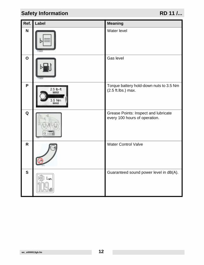
N Water level
O Gas level
P Torque battery hold-down nuts to 3.5 Nm (2.5 ft.lbs.) max.
Q Grease Points: Inspect and lubricate every 100 hours of operation.
R Water Control Valve
S Guaranteed sound power level in dB(A).
Ref. Label Meaning

RD 11 /... Safety Information
wc_si000013gb.fm 13
T A nameplate listing the Model Number, Item Number, Revision, and Serial Num-ber is attached to each unit. Please record the information found on this plate so it will be available should the name-plate become lost or damaged. When ordering parts or requesting service infor-mation, you will always be asked to spec-ify the model, item number, revision number, and serial number of the unit.
Variable speed throttle
Variable choke
Variable direction control
Vibration control
Key switch, engine start:OffOnStart
Ref. Label Meaning

Safety Information RD 11 /...
wc_si000013gb.fm 14
This machine may be covered by one or more patents.
Ref. Label Meaning

RD 11 /... Technical Data
wc_td000022gb.fm 15
3. Technical Data
3.1 Engine
Item Number Revision
0007693 128 & higher
0007694 128 & higher
0007695 128 & higher
Item No. RD 11A0007693
RD11 AEC0007695
RD 11V0007694
Engine
Engine Type 4-stroke, 2 cylinder, air cooled
Engine Make Honda Honda Briggs & Stratton
Engine Model GX 610 QDF Vanguard 350447
Rated Power kW (Hp) 13.4 (18)
Displacement cm³ (in³) 614 (37.5) 570 (34.7)
Spark Plug (NGK) BPR6ES / (NGK) BPR6ESHigh Heat
Champion RC12YC
Electrode Gap mm (in) 0.71–0.79 (0.028–0.031) 0.76 (0.030)
Engine Speed - full load rpm 3200
1800Engine Speed - idle rpm
Valve Clearance (cold)intake:exhaust:
mm (in.) 0.10–0.16 (0.004–0.006)0.10–0.16 (0.004–0.006)
Battery V 12 VDC
Air Cleaner type Dual Element
Fuel type Regular Unleaded Gasoline
Fuel Tank Capacity l (gal.) 24 (6.3)
Fuel Consumption l (gal.)/hr. 4.6 (1.2)

Technical Data RD 11 /...
wc_td000022gb.fm 16
3.2 Roller
3.3 Lubrication
Item No. RD 11A0007693
RD 11AEC0007695
RD 11V0007694
Roller
Dry Weight 925 (2040) 1067 (2353) 925 (2040)
Curb Clearance: RightLeft
mm (in.) 470 (18.4)205 (8.1)
390 (15.4)210 (8.7)
470 (18.4)205 (8.1)
Water Tank Capacity l (gal.) 151 (40)
Outside Turning Radius m (ft.) 2.8 (9.2)
Forward / Reverse Speed
m (ft.) /min.
0–126 (0–414)
Gradeability 27% (12º)
Vibration Frequency Hz (vpm) 65 (3900)
Item No. RD 11A0007693
RD 11AEC0007695
RD 11V0007694
Lubrication
Engine Lubrication typel (pt.)
SAE 10W30 Class SG, SF,or SE rated1.6 (3.5)
Hydraulic System typel (gal)
Premium grade, Anti-wear hydraulic fluid 10W3021.6 (5.7)
Exciter type Wheel Bearing Grease Filmite EMB
Rear Drum Drive Bearing
typeqty.
Shell Alvania No. 2 Grease (1 grease fitting)2–3 shots with hand-held grease gun
Front Drum Drive Bearing
type Sealed Bearings —No lubrication required
Articulated Joint typeqty.
Shell Alvania No. 2 Grease (1 grease fitting)2–3 shots with hand-held grease gun

RD 11 /... Technical Data
wc_td000022gb.fm 17
3.4 Dimensions
3.5 Sound and Vibration Measurements
The required sound specification, Paragraph 1.7.4.f of 89/392/EECMachinery Directive, is:
The sound pressure level at operator’s location (LpA) = 89.1 dB(A).
The guaranteed sound power level (LWA) = 109 dB(A).
These noise values were obtained at the operator's location accordingto ISO 3744 for the sound power level (LWA) and ISO 6081 for thesound pressure level (LpA).
The weighted effective acceleration value, determined according toISO 8662 Part 1, is approximately:
Hands = 5.65 m/s2, Feet = 0.64 m/s2, Seat = 1.05 m/s2.
The sound and vibration measurements were obtained with themachine operating on hard asphalt at maximum RPM and top speed.

Operation RD 11 /...
wc_tx000048gb.fm 18
4. Operation
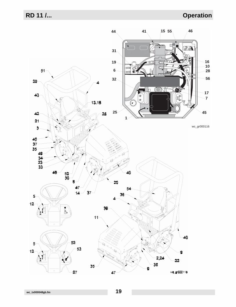
4.1 Operation and Service Locations
See Graphic: wc_gr000115 & wc_gr000114Ref. Description Ref. Description
1. Air Cleaner 29. Water Tank
2. Articulated Joint 30. Lockarm
3. Water Level Sight Gauge 31. Drive Manifold Assembly(Valve Block)
4. Hand holds 32. Oil Filter - Engine
5. Choke Lever 33. Rear Drum Fill/Drain Plug
6. Coupling - Engine 34. Rear Drum - Static
7. Dipstick 35. Scraper Bar (4 places)
8. Drain Plug - Hydraulic Tank 36. Sightglass - Hydraulic Tank
9. Drive Motor 37. Sprinkler Tube (4)
10. Drive Pump 38. Steering Wheel
11. Engine Hood 39. Steering Cylinder
12. Engine Throttle Control 40. Tiedown (2 places)
13. Vibration Control Button 41. Battery disconnect (RD11AEC)
14. Exciter Motor 42. Water System Control - Front Drum
15. Exciter/Steering Pump 43. Water System Control - Rear Drum
16. Filter - Return Line 44. Battery
17. Filter - Suction Line 45. Hour Meter / Tachometer
18. Forward / Reverse Control 46. Suction Line
19. Forward / Reverse Control Cable 47. Grease Fitting - Exciter (2 places)
20. Front Drum - Vibratory 48. Fuel Level Sight Gauge
21. Fuel Tank Access Door 49. Lifting Eye (4 places)
22. Fuel Filter (under floor panel) 50. Step (2)
23. Grease Fitting - Rear Drum 51. ROPS
24. Grease Fittings - Articulated Joint (4 places)
52. Emergency Stop Pushbutton / Parking Brake (RD11AEC)
25. Hydraulic Tank Fill Port 53. Horn Switch (RD11AEC)
26. Identification Plate 54. Adjustable Seat with Seatbelt (RD11AEC)
27. Ignition Switch 55. Brake Release-tow valve (RD11AEC)
28. Steering/Exciter Manifold 56. Horn (RD11AEC)
RD 11 /... Operation
wc_tx000048gb.fm 19
wc_gr000116
44 41 15 55 46
161028
56
177
451
25
32
6
19
31
Operation RD 11 /...
wc_tx000048gb.fm 20
4.2 Application
This machine is designed as a lightweight roller to be used in thecompaction of sublayers and finish layers of asphalt on roads,driveways, parking lots, and other types of asphalt-covered surfaces.Do not use this machine for any other purpose.
4.3 Recommended Fuel
The engine requires regular grade unleaded gasoline. Use only fresh,clean gasoline. Gasoline containing water or dirt will damage fuelsystem. Consult engine owner’s manual for complete fuelspecifications.
4.4 Before Starting
Before starting the machine check the following:
• Engine oil level
• Hydraulic fluid level
• Condition of fuel lines
• Condition of air cleaner
• Operation of the brake system
• Fuel level
• Water level
• Safety belt
• Scraper bars are clean and properly adjusted
Note: All fluid levels should be checked with the machine on a levelsurface.
Ensure that regular maintenance has been carried out.
Ensure that the driver's platform is clean.
Always use the steps and handrails when climbing on and off themachine.

RD 11 /... Operation
wc_tx000048gb.fm 21
4.5 Starting (RD11A / RD11V)
See Graphic: wc_gr000123
4.5.1 If the engine is cold, place the choke lever in the closed position (b2).If the engine is warm, place the choke control in the open position (b1).
4.5.2 Set the forward/reverse control in the neutral position (e2).
Note: The roller will not start unless the forward/reverse control is inneutral.
4.5.3 Check that the parking brake is set (d).
4.5.4 Turn the ignition switch (f) to start the engine. If exciter indicator light(g) is on, turn vibration off.
CAUTION: Do not crank the engine starter for more than 15 secondsat one time. Longer cranking cycles could lead to starter damage.
4.5.5 Gradually place the choke lever to the open position (b1) as the enginewarms up. Allow the engine to warm up for a few minutes beforeoperating the roller.
wc_gr000123
a2
a1
b2
b1
c
d
g
f
e3 e2 e1

Operation RD 11 /...
wc_tx000048gb.fm 22
4.6 Stopping/Parking (RD11A / RD11V)
See Graphic: wc_gr000123
4.6.1 Turn vibration off.
4.6.2 Close both watering valves.
4.6.3 Return engine throttle to idle (a1) by pressing the throttle switch andallow engine to cool down.
4.6.4 Stop engine by turning ignition switch to “OFF”.
4.6.5 Set parking brake.To set the brake (d), pull the brake lever up untilbrake pad engages drum. To release, lower lever. Always set parkingbrake before leaving machine.
The parking brake is connected to the brake pads and can be adjustedby turning the knob (c) on the end of the handle. See Parking BrakeAdjustment.
Note: The parking brake engages the rear drum only.
CAUTION: Avoid parking roller on a hill or incline. If roller must beparked on a hill, block drums in addition to setting brake to preventroller from moving.
wc_gr000123
a2
a1
b2
b1
c
d
g
f
e3 e2 e1
RD 11 /... Operation
wc_tx000048gb.fm 23
4.7 Direction and Speed (RD11A / RD11V)
See Graphic: wc_gr000123
The forward/reverse lever controls both the direction and speed of theroller. Use the control lever, rather than the throttle, to control thespeed of the machine while compacting.
Daily, before operating, check the machine for “drift” (movement withthe forward/reverse control in the NEUTRAL position) and adjust asneeded. See Adjusting the Drive Control Cable.
Speed is controlled by the amount the lever is moved in the directionof travel—forward (e1) or reverse (e3).
During operation, to run the machine at full throttle (a2), quickly pressand release the throttle switch. This ensures maximum travel speedsand will produce the best compaction results. Operating the machineat slower engine speeds will reduce compaction, slow down machinefunctions, and damage hydraulic components.
CAUTION: Holding the throttle switch in for a period of time will trip thecircuit breaker.
4.8 Braking Machine (RD11A / RD11V)
See Graphic: wc_gr000123
The machine will brake automatically when the control lever is returnedto neutral (e2). If machine continues to drift, shift the control leverslightly in the opposite direction to stop movement and then returnlever to neutral. If it will not remain stationary in neutral, adjust asneeded. See Adjusting the Drive Control Cable.
Note: Do not stop the machine using the parking brake! The parkingbrake is not intended to be used to stop the machine.

Operation RD 11 /...
wc_tx000048gb.fm 24
4.9 Starting (RD11AEC)
See Graphic: wc_gr000139
4.9.1 If the engine is cold, place the choke lever in the closed position (b2).If the engine is warm, place the choke control in open position (b1).
4.9.2 Set the forward/reverse control in the neutral position (c2).
Note: The roller will not start unless the forward/reverse control is inneutral.
4.9.3 Push the emergency stop pushbutton (d) to make sure that the parkingbrake is set.
4.9.4 Turn the ignition switch (e) to start engine.
CAUTION: Do not crank the engine starter for more than 15 secondsat one time. Longer cranking cycles could lead to starter damage.
4.9.5 Gradually place the choke lever to the open position (b1) as the enginewarms up. Allow the engine to warm up for a few minutes beforeoperating roller.
4.9.6 Disengage the parking brake by turning the emergency stop button (d)until it pops out.
wc_gr000139
c3 c2 c1
d
e
b1
b2
a2
a1
RD 11 /... Operation
wc_tx000048gb.fm 25
4.10 Stopping/Parking (RD11AEC)
See Graphic: wc_gr000139
4.10.1 Turn vibration off.
4.10.2 Close both watering valves.
4.10.3 Return engine throttle to idle (a1) by pressing the throttle switch andallow engine to cool down.
4.10.4 Stop engine by turning ignition switch to “OFF”.
4.10.5 To engage the parking brake (d), push the emergency stop button.This switch engages a hydraulically activated brake on the drivemotors.Always set parking brake before leaving machine.
CAUTION: Avoid parking roller on a hill or incline. If roller must beparked on a hill, block drums in addition to setting brake to preventroller from moving.

Operation RD 11 /...
wc_tx000048gb.fm 26
4.11 Direction and Speed (RD11AEC)
See Graphic: wc_gr000139
The forward/reverse lever controls both the direction and speed of theroller. Use the control lever, rather than the throttle, to control thespeed of the machine while compacting.
Daily, before operating, check the machine for “drift” (movement withthe forward/reverse control in the NEUTRAL position) and adjust asneeded. See Adjusting the Drive Control Cable.
Speed is controlled by the amount the lever is moved in the directionof travel—forward (c1) or reverse (c3).
During operation, to run the machine at full throttle (a2), quickly pressand release the throttle switch. This ensures maximum travel speedsand will produce the best compaction results. Operating the machineat slower engine speeds will reduce compaction, slow down machinefunctions, and damage hydraulic components.
CAUTION: Holding the throttle switch in for a period of time will trip thecircuit breaker.
Note: This machine is fitted with an "Operator Presence" safetysystem which prevents the machine from moving if an operator is notseated in the driver's seat.
Do not use the machine without the ROPS in place. The ROPS isdesigned to protect the operator in a rollover accident.
Always wear the seat belt provided when operating the roller.
WARNING
WARNING

RD 11 /... Operation
wc_tx000048gb.fm 27
4.12 Braking Machine (RD11AEC)
See Graphic: wc_gr000139
Automatic functions
The machine will brake automatically when the control lever is returnedto neutral. If machine continues to drift, shift the control lever slightly inthe opposite direction to stop movement and then return lever toneutral. If it will not remain stationary in neutral, adjust per SectionAdjusting the Drive Control Cable.
The emergency stop / parking brakes will automatically apply when:
• The emergency stop button is pushed.
• The engine is off.
• A loss of hydraulic or electrical power occurs.
• The operator rises from the driver's seat, activating the Operator Presence System.
Note: The Operator Presence System will only trip after a one-halfsecond delay.
Emergency stop pushbutton
When pushed, the emergency stop button not only stops all travel(either forward or reverse) and applies the brake, but it also stopsvibration of the exciter.
When the emergency stop button is reset, vibration will not resumeuntil it is turned ON. See Vibration.
Before releasing the emergency stop button, place the Forward/Reverse Control in neutral.
wc_gr000139
c3 c2 c1
d
e
b1
b2
a2
a1

Operation RD 11 /...
wc_tx000048gb.fm 28
4.13 Vibration (RD11A / RD11V)
See Graphic: wc_gr000117
Vibration is turned “ON” or “OFF” by a push button (a) located in the
uppermost portion of the Forward/Reverse Control. Push the button to
turn vibration on; push it again to turn it off. Vibration can be turned on
while operating in either forward or reverse and will remain on until it is
switched off.
CAUTION: If machine has been turned off with the vibration on, the
vibration will come on as soon as machine is restarted. Therefore, for
easier starting and to keep surface finish smooth, be ready to switch
vibration off should it come on while cranking engine.
Note: Vibration will remain on even when the forward/reverse control
is in neutral. When operating on asphalt, to keep surface finish
smooth, turn vibration off before stopping roller.

RD 11 /... Operation
wc_tx000048gb.fm 29
4.14 Vibration (RD11AEC)
See Graphic: wc_gr000117
Vibration is turned “ON” or “OFF” by a pushbutton (a) located in theuppermost portion of the Forward/Reverse Control. Press the button toturn vibration on; press it again to turn it off. Vibration can be turned onwhile operating in either forward or reverse and will remain on until it isswitched off.
Note: Vibration will always be OFF when the engine is started.
Note: Vibration will remain on even when the forward/reverse controlis in neutral. When operating on asphalt, to keep surface finishsmooth, turn vibration off before stopping roller.
Note: Pressing the emergency stop button will also stop vibration.After the emergency stop button has been reset, press pushbutton (a)to restart vibration.

Operation RD 11 /...
wc_tx000048gb.fm 30
4.15 Watering System
See Graphic: wc_gr000118
The watering system is controlled by two valves, one for each drum.The valve handles (a) are located to the right of the operator. Rotatethe valve handles to control the amount of water being applied to thedrum.
4.16 Articulation Joint Lockarm
See Graphic: wc_gr000119
A lockarm (a), located above the articulated joint, is provided to securethe front and rear halves of the roller together. Once secured, thelockarm prevents the two halves from swinging together.
To avoid being pinched by machine halves, set the lockarm beforelifting the machine for transport or repairs!
To set lockarm, release it from its holder and swing it out from its storedposition. Place the forward end of the arm into the hole provided in thefront frame of the machine. Secure it in this position using the largehairpin cotter (b) provided.
WARNING

RD 11 /... Operation
wc_tx000048gb.fm 31
4.17 Adding Ballast to Rear Drum
See Graphic: wc_gr000120
The rear drum can be filled with ballast to provide additional weight.Add ballast through plug opening (a).
Drum Capacity: 30.2 gal. (114 liters)
Added Weight (water ballast): 250 lbs. (113 Kg)
If water is used as ballast, add antifreeze or drain drum after use, inareas where temperatures are below freezing.
Operation RD 11 /...
wc_tx000048gb.fm 32
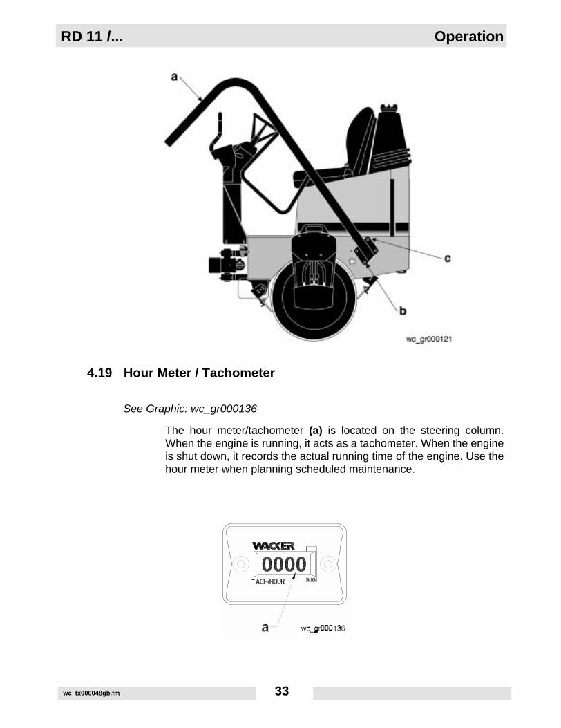
4.18 Roll Over Protection Structure (ROPS)
See Graphic: wc_gr000121
The machine is fitted with a Roll Over Protection Structure (ROPS).The machine is normally delivered to the customer with the ROPSfolded forward to facilitate transport.
Before using the machine, position the ROPS in the fully uprightposition as follows:
4.18.1 Support the ROPS (a) using a crane and suitable rigging capable ofsupporting 105 lbs. (48 kg.), or two individuals capable of supportingthe ROPS.
4.18.2 Loosen the screws (c) (one on each side) without removing them.
4.18.3 Raise the ROPS to the upright position.
4.18.4 Insert the screws into the holes (b) and torque all screws to 88 ft.lbs.(120 Nm).
4.18.5 Remove the rigging from the ROPS.
CAUTION: Do not use the ROPS to lift the machine.
Each month, check that the screws holding the ROPS in place aretight. Check that the ROPS frame is not rusty, cracked, broken ordamaged in any way.
If the frame has been removed from the machine, it must be reinstalledbefore the machine is used. When reinstalling a safety frame, use theoriginal nuts and bolts.
Keep the safety frame upright when working with the roller, and use thesafety belt provided.
To remove the ROPS:
4.18.6 Support the ROPS with a crane and rigging with sufficient capacity tosupport 105 lbs. (48 Kg).
4.18.7 Remove all the screws securing the ROPS to the machine.
4.18.8 Lift the ROPS from the machine and place it on the ground.
CAUTION: Do not use the ROPS to lift the machine.
Do not use the machine without the ROPS in place. The ROPS isdesigned to protect the operator in a rollover accident.
Always wear the safety belt provided when operating the roller.
WARNING
WARNING
RD 11 /... Operation
wc_tx000048gb.fm 33
4.19 Hour Meter / Tachometer
See Graphic: wc_gr000136
The hour meter/tachometer (a) is located on the steering column.When the engine is running, it acts as a tachometer. When the engineis shut down, it records the actual running time of the engine. Use thehour meter when planning scheduled maintenance.

Operation RD 11 /...
wc_tx000048gb.fm 34
4.20 Operation on Slopes
See Graphic: wc_gr000122
When operating on slopes or hills special care must be taken to reducethe risk of personal injury or damage to the equipment. Alwaysoperate the machine up and down hills rather than from side to side.For safe operation and for protection of the engine, continuous dutyuse should be restricted to front/rear slopes of 17° (30% grade) or less.
NEVER operate machine on side slopes. The machine may roll over,even on stable ground.
WARNING

RD 11 /... Operation
wc_tx000048gb.fm 35
4.21 Hood Prop Bar
See Graphic: wc_gr000135
The hood prop bar (a) is designed to prevent the hood from shuttinginadvertently while maintenance is being performed in the enginecompartment. To close the hood, release the prop by lifting up on thebottom of the bar, then lower the hood.
4.22 Battery Disconnect (RD11AEC)
See Graphic: wc_gr000138
This machine is equipped with a battery disconnect switch locatedadjacent to the battery.
To disconnect and isolate the electrical system from the battery, turnthe selector key (a) counter-clockwise 1/4 of a turn and remove.
To reconnect the battery, insert the selector key and turn clockwise tothe end of its travel.
Isolate the battery using this switch before performing anymaintenance operations on electrical equipment.
WARNING

Operation RD 11 /...
wc_tx000048gb.fm 36
4.23 Operator Presence System (RD11AEC)
See Graphic: wc_gr000137
The machine is equipped with an “operator presence system”. Thissystem is part of the driver's seat and senses the weight of an operatorin the seat. If the operator is not sitting in the driver's seat, the rollerwill NOT drive, and the exciter will NOT vibrate. If the operator leavesthe driver's seat, the roller will stop moving and vibrating. When theoperator sits down again, the forward/reverse lever must be placed inthe neutral position before the roller can be driven or the vibration canbe started.
A one-half second delay keeps the system from tripping when the rollerpasses over a bump.
The seat can be adjusted as follows:
• Knob (a) for adjusting the seat tension to the driver's weight.
• Lever (b) for adjusting the distance from the seat to the driving controls.
Note: Do not change position of the driver’s seat while the machine ismoving. The “OPERATOR PRESENCE” safety device will prevent allmachine movements if an operator is not seated.
Always wear the seat belt provided when operating the roller.
WARNING
RD 11 /... Maintenance
wc_tx000049gb.fm 37
5. Maintenance
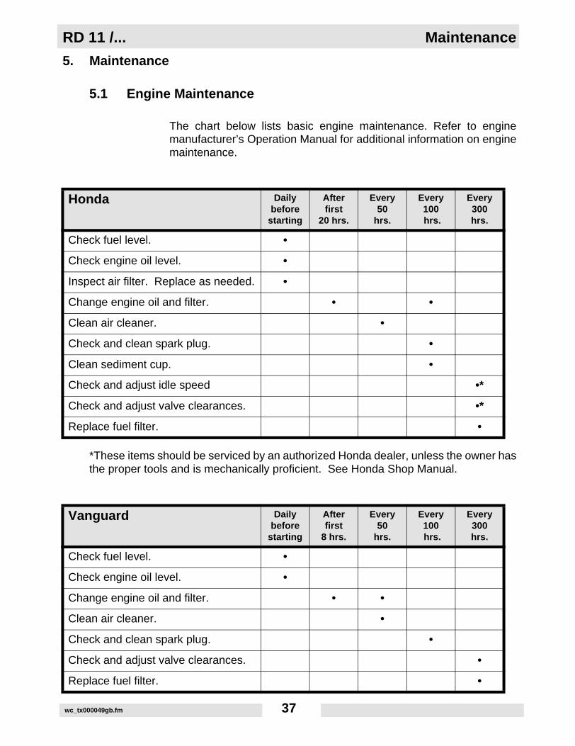
5.1 Engine Maintenance
The chart below lists basic engine maintenance. Refer to enginemanufacturer’s Operation Manual for additional information on enginemaintenance.
*These items should be serviced by an authorized Honda dealer, unless the owner hasthe proper tools and is mechanically proficient. See Honda Shop Manual.
Honda Dailybefore
starting
Afterfirst
20 hrs.
Every50
hrs.
Every100 hrs.
Every300hrs.
Check fuel level. •
Check engine oil level. •
Inspect air filter. Replace as needed. •
Change engine oil and filter. • •
Clean air cleaner. •
Check and clean spark plug. •
Clean sediment cup. •
Check and adjust idle speed •*
Check and adjust valve clearances. •*
Replace fuel filter. •
Vanguard Dailybefore
starting
Afterfirst
8 hrs.
Every50
hrs.
Every100 hrs.
Every300hrs.
Check fuel level. •
Check engine oil level. •
Change engine oil and filter. • •
Clean air cleaner. •
Check and clean spark plug. •
Check and adjust valve clearances. •
Replace fuel filter. •

Maintenance RD 11 /...
wc_tx000049gb.fm 38
5.2 Maintenance Schedule
Periodically:
• Check operation of parking brake, making sure it engages.
• Check for leaks around hydraulic hoses and connections.
• Clean engine exterior, cooling fins, and blower housing.
• Check electrical wiring and connections.
• Check operation of neutral safety switch.
New Machines:
• Change engine oil per engine schedule.
• Replace hydraulic system return line filter after first month or 100 hours of operation.
All machines:
• Increase air cleaner / filter inspections and cleaning under dusty conditions.
RD 11 /... Dailybefore
starting
Every100hrs.
Every600hrs.
Every1200hrs.
Check and tighten external hardware. •
Check level of hydraulic fluid. •
Grease articulated joint. •
Grease rear drum drive bearing. •
Grease exciter bearing. •
Change hydraulic system return line filter. •
Check and adjust scraper bars. •
Clean battery terminals. •
Change hydraulic oil. •

RD 11 /... Maintenance
wc_tx000049gb.fm 39
5.3 Fuel Filter
See Graphic: wc_gr000163
5.3.1 Change in-line fuel filter (a) once a year. Check fuel lines and fittingsdaily for cracks or leaks. Replace as needed.
Gasoline is extremely flammable! Turn engine off and allow engine tocool before replacing fuel filter.
Note: The fuel filter is located under the floor panel of the operatingplatform.
5.4 Engine Oil Drain
See Graphic: wc_gr000164
The engine oil drain (a) has been routed to the outside of the front halfof the RD-11. This is to make draining easier and to help keep theengine compartment clean.

Maintenance RD 11 /...
wc_tx000049gb.fm 40
5.5 Engine Oil
See Graphic: wc_gr000173 (RD11A / RD11AEC)See Graphic: wc_gr000172 (RD11V)
Drain oil while engine is still warm. To drain oil:
5.5.1 Remove filler cap (a), drain screw, and washer. Drain oil into a suitablecontainer.
Note: In the interests of environmental protection, place plasticsheeting and a container under the machine to collect the liquid whichdrains off. Dispose of this liquid properly.
5.5.2 Re-insert the drain screw and washer and tighten the screw securely.
5.5.3 Fill the engine with the recommended oil to the upper limit mark on thedipstick (b). See Technical Data for correct oil type and amount.
Danger of burns! Care must be taken when draining hot engine oil. Hotoil can burn!
WARNING

RD 11 /... Maintenance
wc_tx000049gb.fm 41
5.6 Oil Filter (Honda)
See Graphic: wc_gr000165
Replace the oil filter after every 200 hours of operation.
To change filter:
5.6.1 Drain the engine oil. See Engine Oil. Remove used filter.
5.6.2 Before installing new filter, lightly oil filter gasket (a) with fresh, cleanengine oil. Screw filter on by hand until gasket makes contact, thentighten an additional 7/8 turn.
5.6.3 Fill the engine with the recommended oil. See Engine Oil.
5.6.4 Start and run engine to check for leaks. Stop engine. Recheck oil leveland add oil if required. Refer to engine owner’s manual.
5.7 Oil Filter (Vanguard)
See Graphic: wc_gr000174
Replace oil filter every 100 hours of operation.
5.7.1 Drain engine oil and replace with fresh oil before removing used oilfilter. See Technical Data for oil quantity and type.
Note: In the interests of environmental protection, place a plastic sheetand a container under the machine to collect any liquid which drainsoff. Dispose of this liquid in accordance with environmental protectionlegislation.
5.7.2 Remove used filter, and before installing new filter, lightly oil filtergasket with fresh, clean engine oil.
5.7.3 Screw filter (a) on by hand until gasket makes contact, then tighten anadditional 1/2 to 3/4 turn.
5.7.4 Start and run engine to check for leaks. Stop engine. Recheck oil leveland add oil if required. See Engine Lubrication.
Maintenance RD 11 /...
wc_tx000049gb.fm 42
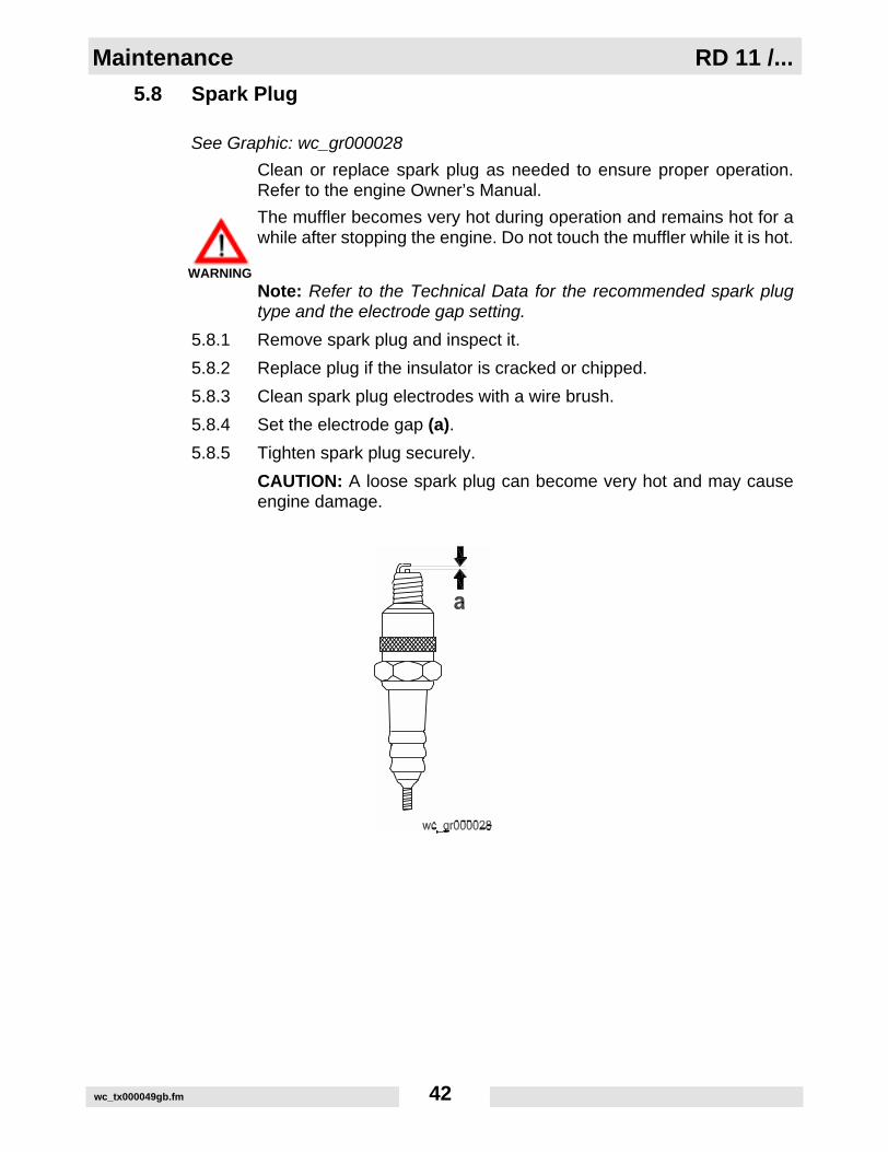
5.8 Spark Plug
See Graphic: wc_gr000028
Clean or replace spark plug as needed to ensure proper operation.Refer to the engine Owner’s Manual.
The muffler becomes very hot during operation and remains hot for awhile after stopping the engine. Do not touch the muffler while it is hot.
Note: Refer to the Technical Data for the recommended spark plugtype and the electrode gap setting.
5.8.1 Remove spark plug and inspect it.
5.8.2 Replace plug if the insulator is cracked or chipped.
5.8.3 Clean spark plug electrodes with a wire brush.
5.8.4 Set the electrode gap (a).
5.8.5 Tighten spark plug securely.
CAUTION: A loose spark plug can become very hot and may causeengine damage.
WARNING
RD 11 /... Maintenance
wc_tx000049gb.fm 43
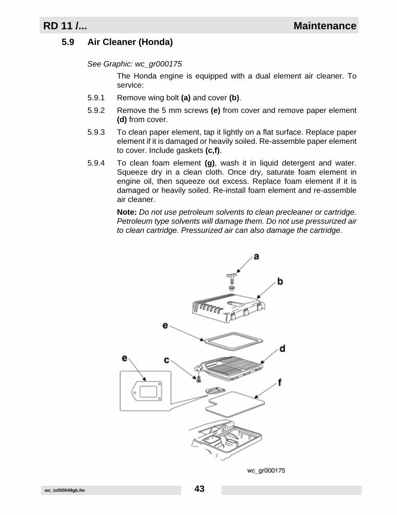
5.9 Air Cleaner (Honda)
See Graphic: wc_gr000175
The Honda engine is equipped with a dual element air cleaner. Toservice:
5.9.1 Remove wing bolt (a) and cover (b).
5.9.2 Remove the 5 mm screws (e) from cover and remove paper element(d) from cover.
5.9.3 To clean paper element, tap it lightly on a flat surface. Replace paperelement if it is damaged or heavily soiled. Re-assemble paper elementto cover. Include gaskets (c,f).
5.9.4 To clean foam element (g), wash it in liquid detergent and water.Squeeze dry in a clean cloth. Once dry, saturate foam element inengine oil, then squeeze out excess. Replace foam element if it isdamaged or heavily soiled. Re-install foam element and re-assembleair cleaner.
Note: Do not use petroleum solvents to clean precleaner or cartridge.Petroleum type solvents will damage them. Do not use pressurized airto clean cartridge. Pressurized air can also damage the cartridge.

Maintenance RD 11 /...
wc_tx000049gb.fm 44
5.10 Air Cleaner (Vanguard)
See Graphic: wc_gr000176
To service air cleaner:
5.10.1 Remove cover (a), knob (b), and retaining plate (c).
5.10.2 Remove foam precleaner (e) from filter cartridge (d).
5.10.3 Wash precleaner in liquid detergent and water. Squeeze dry in a cleancloth. Saturate precleaner in engine oil, squeeze out excess oil.Replace precleaner if it is damaged or heavily soiled.
5.10.4 To clean cartridge, remove and tap lightly on a flat surface. Replacecartridge if it is damaged or heavily soiled.
Note: Do not use petroleum solvents to clean precleaner or cartridge.Petroleum type solvents will damage them. Do not use pressurized airto clean cartridge. Pressurized air can also damage the cartridge.
RD 11 /... Maintenance
wc_tx000049gb.fm 45
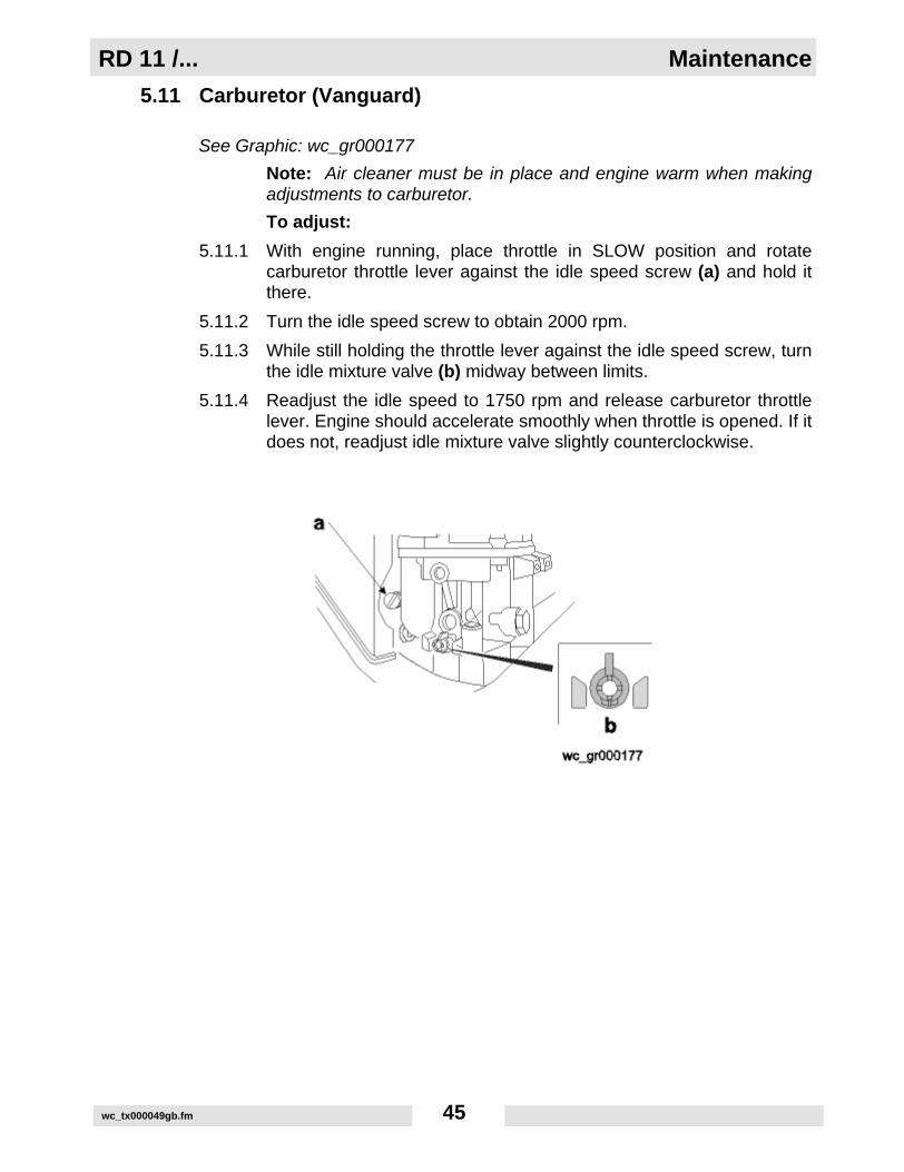
5.11 Carburetor (Vanguard)
See Graphic: wc_gr000177
Note: Air cleaner must be in place and engine warm when makingadjustments to carburetor.
To adjust:
5.11.1 With engine running, place throttle in SLOW position and rotatecarburetor throttle lever against the idle speed screw (a) and hold itthere.
5.11.2 Turn the idle speed screw to obtain 2000 rpm.
5.11.3 While still holding the throttle lever against the idle speed screw, turnthe idle mixture valve (b) midway between limits.
5.11.4 Readjust the idle speed to 1750 rpm and release carburetor throttlelever. Engine should accelerate smoothly when throttle is opened. If itdoes not, readjust idle mixture valve slightly counterclockwise.
Maintenance RD 11 /...
wc_tx000049gb.fm 46
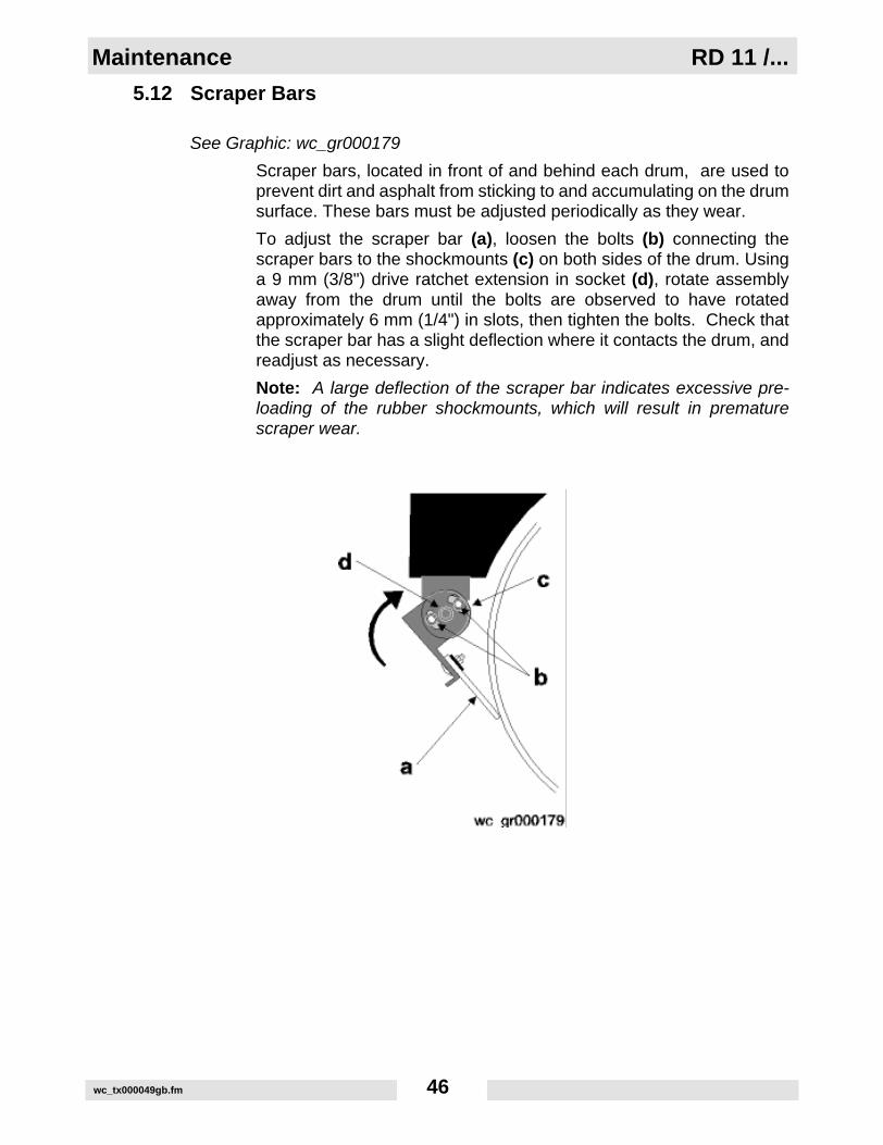
5.12 Scraper Bars
See Graphic: wc_gr000179
Scraper bars, located in front of and behind each drum, are used toprevent dirt and asphalt from sticking to and accumulating on the drumsurface. These bars must be adjusted periodically as they wear.
To adjust the scraper bar (a), loosen the bolts (b) connecting thescraper bars to the shockmounts (c) on both sides of the drum. Usinga 9 mm (3/8") drive ratchet extension in socket (d), rotate assemblyaway from the drum until the bolts are observed to have rotatedapproximately 6 mm (1/4") in slots, then tighten the bolts. Check thatthe scraper bar has a slight deflection where it contacts the drum, andreadjust as necessary.
Note: A large deflection of the scraper bar indicates excessive pre-loading of the rubber shockmounts, which will result in prematurescraper wear.

RD 11 /... Maintenance
wc_tx000049gb.fm 47
5.13 Grease Fittings
See Graphic: wc_gr000178
See Technical Data - Lubrication.
Articulated Joint:
The articulated joint is equipped with grease fittings (a) for lubrication.
Rear Drum:
The rear drum drive bearing is equipped with a grease fitting (b)located at the center of the drum behind the right rear drum support.
Exciter:
The exciter is grease lubricated. There are two grease fittings (c), oneon each side of the machine, located behind the front drum supports.

Maintenance RD 11 /...
wc_tx000049gb.fm 48
5.14 Hydraulic System Cleanliness
Keeping the hydraulic oil clean is a vital factor affecting the service lifeof hydraulic components. Oil in hydraulic systems is used not only totransfer power, but also to lubricate the hydraulic components used inthe system. Keeping the hydraulic system clean will help avoid costlydowntime and repairs.
Major sources of hydraulic system contamination include:
• Particles of dirt introduced when the hydraulic system is opened for maintenance or repair.
• Contaminants generated by the mechanical components of the system during operation.
• Improper storage and handling of hydraulic oil.
• Use of the wrong type of hydraulic oil.
• Leakage in lines and fittings.
To minimize hydraulic oil contamination:
CLEAN hydraulic connections before opening lines. When adding oil,clean hydraulic tank filler cap and surrounding area before removing.
AVOID opening pumps, motors, or hose connections unlessabsolutely necessary.
PLUG or cap all open hydraulic connections while servicing system.
CLEAN and cover the containers, funnels, and spouts used to storeand transfer hydraulic oil.
CHANGE hydraulic filters and oils at the recommended serviceintervals.
RD 11 /... Maintenance
wc_tx000049gb.fm 49
5.15 Hydraulic Oil Requirements
Wacker recommends the use of a good petroleum-based, anti-wearhydraulic oil in the hydraulic system of this equipment. Good anti-wearhydraulic oils contain special additives to reduce oxidation, preventfoaming, and they provide for good water separation.
When selecting hydraulic oil for your machine, be sure to specify anti-wear properties. Most hydraulic oil suppliers will provide assistance infinding the correct hydraulic oil for your machine.
Avoid mixing different brands and grades of hydraulic oils.
Most hydraulic oils are available in different viscosities.
The SAE number for an oil is used strictly to identify viscosity—it doesnot indicate the type of oil (engine, hydraulic, gear, etc.).
When selecting a hydraulic oil be sure it matches the specified SAEviscosity rating and is intended to be used as a hydraulic oil. SeeTechnical Data - Lubrication.
Maintenance RD 11 /...
wc_tx000049gb.fm 50
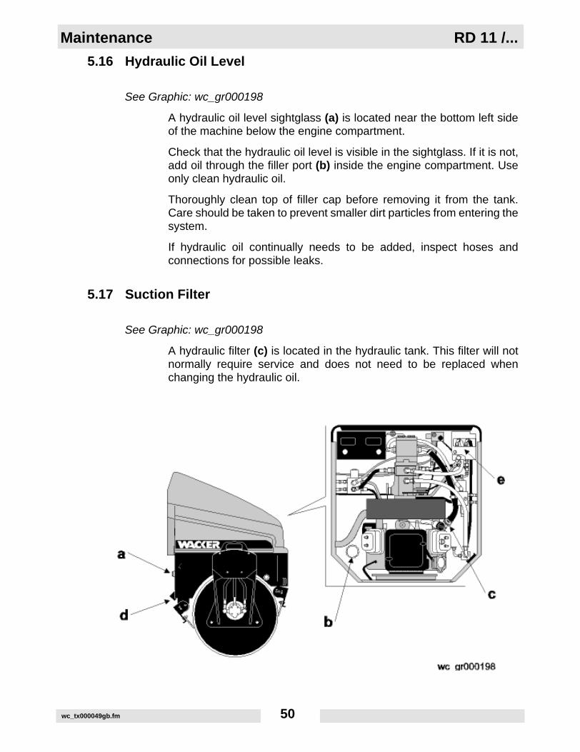
5.16 Hydraulic Oil Level
See Graphic: wc_gr000198
A hydraulic oil level sightglass (a) is located near the bottom left sideof the machine below the engine compartment.
Check that the hydraulic oil level is visible in the sightglass. If it is not,add oil through the filler port (b) inside the engine compartment. Useonly clean hydraulic oil.
Thoroughly clean top of filler cap before removing it from the tank.Care should be taken to prevent smaller dirt particles from entering thesystem.
If hydraulic oil continually needs to be added, inspect hoses andconnections for possible leaks.
5.17 Suction Filter
See Graphic: wc_gr000198
A hydraulic filter (c) is located in the hydraulic tank. This filter will notnormally require service and does not need to be replaced whenchanging the hydraulic oil.

RD 11 /... Maintenance
wc_tx000049gb.fm 51
5.18 Changing Hydraulic Oil & Filter
See Graphic: wc_gr000198
All oils eventually shear or thin out with use, reducing their lubricatingability. In addition, heat, oxidation, and contamination may cause theformation of sludge, gum, or varnish in the system. For these reasons,it is important to change the hydraulic oil at specified intervals. SeeMaintenance Schedule.
5.18.1 Remove filler cap (b) from top of hydraulic tank.
5.18.2 Remove drain plug (d) and allow hydraulic fluid to drain.
Note: In the interests of environmental protection, place plasticsheeting and a container under the machine to collect the liquid whichdrains off. Dispose of this liquid properly.
5.18.3 Unscrew the return line filter (e) and replace filter cartridge.
5.18.4 Install drain plug.
5.18.5 Fill hydraulic tank through filler port with clean hydraulic fluid.
5.18.6 Bleed hydraulic system. See Bleeding the Hydraulic System.

Maintenance RD 11 /...
wc_tx000049gb.fm 52
5.19 Bleeding the Hydraulic System
See Graphic: wc_gr000199
5.19.1 Fill the hydraulic system with clean hydraulic oil until it is visible in thesightglass. Do not re-use used hydraulic oil.
5.19.2 Disconnect the line (a) from drive pump. Fill pump case with hydraulicoil through the open connection. Reconnect the line.
5.19.3 Disconnect spark plug wires to prevent engine from starting and crankengine 5 – 10 seconds. This will allow oil to fill inlet lines.
5.19.4 Reconnect spark plug wires and place forward/reverse control lever inNEUTRAL. Start engine and run machine at idle for 3 – 4 minutes.
5.19.5 With engine still running at idle, move control slowly back and forthfrom forward to reverse for a short time to bleed air trapped in drivecircuit.
5.19.6 Gradually increase engine speed to full throttle and operate all controlsto bleed remaining air from hydraulic lines.
5.19.7 Check hydraulic oil level and add oil as required.
Note: If drive pump chatters or operation is noisy, turn machine off andcheck for air leaks in the inlet line of the charge pump.

RD 11 /... Maintenance
wc_tx000049gb.fm 53
5.20 Adjusting the Drive Control Cable
See Graphic: wc_gr000200
If the RD11 tends to “drift” in either direction when the forward/reversecontrol is in neutral, the drive control cable must be adjusted.
Check the adjustment with the machine on a hard level surface, theengine running, and the forward/reverse control in NEUTRAL. Thepump control lever (a) should be centered. If the machine does notremain stationary, loosen the jam nuts (b) and move the turnbuckle (c)as needed until movement stops.
If adjusting the turnbuckle does not achieve the desired results, agross adjustment can be made at nut (d) and then fine-tuned asdescribed above.
Maintenance RD 11 /...
wc_tx000049gb.fm 54
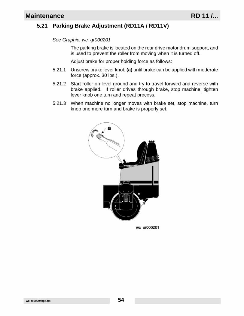
5.21 Parking Brake Adjustment (RD11A / RD11V)
See Graphic: wc_gr000201
The parking brake is located on the rear drive motor drum support, andis used to prevent the roller from moving when it is turned off.
Adjust brake for proper holding force as follows:
5.21.1 Unscrew brake lever knob (a) until brake can be applied with moderateforce (approx. 30 lbs.).
5.21.2 Start roller on level ground and try to travel forward and reverse withbrake applied. If roller drives through brake, stop machine, tightenlever knob one turn and repeat process.
5.21.3 When machine no longer moves with brake set, stop machine, turnknob one more turn and brake is properly set.

RD 11 /... Maintenance
wc_tx000049gb.fm 55
5.22 Throttle Solenoid Adjustment
See Graphic: wc_gr000103
5.22.1 With engine still operating, set the throttle lever stop screw (c) onengine to 3200 rpm.
5.22.2 Shut down engine and then turn key to the first position (don't start theengine). Activate throttle solenoid. While holding the throttle lever (b)on engine to the fully engaged position (as set in step 2), pull cabletight through throttle nut/set screw (d) and secure cable. Disengagesolenoid.
5.22.3 Turn the throttle lever stop screw (c) counter-clockwise three turns.
5.22.4 Start the engine and engage solenoid. Using the 5/16" mounting nutson threaded casing end, adjust top speed to 3200 rpm.
Maintenance RD 11 /...
wc_tx000049gb.fm 56
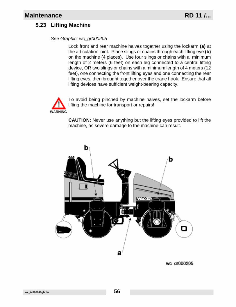
5.23 Lifting Machine
See Graphic: wc_gr000205
Lock front and rear machine halves together using the lockarm (a) atthe articulation joint. Place slings or chains through each lifting eye (b)on the machine (4 places). Use four slings or chains with a minimumlength of 2 meters (6 feet) on each leg connected to a central liftingdevice, OR two slings or chains with a minimum length of 4 meters (12feet), one connecting the front lifting eyes and one connecting the rearlifting eyes, then brought together over the crane hook. Ensure that alllifting devices have sufficient weight-bearing capacity.
To avoid being pinched by machine halves, set the lockarm beforelifting the machine for transport or repairs!
CAUTION: Never use anything but the lifting eyes provided to lift themachine, as severe damage to the machine can result.
WARNING

RD 11 /... Maintenance
wc_tx000049gb.fm 57
5.24 Transporting Machine
See Graphic: wc_gr000204
When transporting the machine place blocks in front of and behindeach drum and use the front and rear tie-down lugs (a) provided tosecurely fasten the machine to the trailer (2 places).
CAUTION: Never use anything but the tiedown lugs provided to tiedown the machine, as severe damage to the machine can result.
5.25 Storage
If unit is to be stored for more than 30 days:
• Drain fuel tank and water tank. Also drain rear drum, if ballast was added.
• Open water valves and drain water from sprinkling system.
• Change engine oil.
• Remove spark plugs and pour approximately 1 ounce (3 ml) of SAE 30W oil into each engine cylinder through spark plug open-ing.
• Install spark plugs. Leave ignition wires disconnected to prevent engine from starting. Crank engine for one or two seconds to dis-tribute oil inside engine cylinders. Connect ignition wires.
• Clean entire roller and engine compartment.
• Remove dirt from cooling fins on engine cylinders and on blower housing.
• Set lockarm to secure roller halves together.
• Remove battery from machine and charge it periodically.
• Cover entire machine and place in a dry, protected area.
Maintenance RD 11 /...
wc_tx000049gb.fm 58
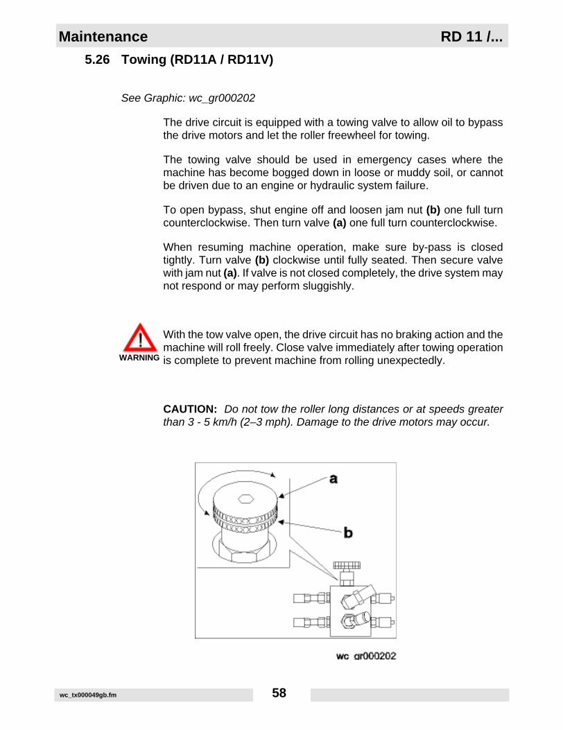
5.26 Towing (RD11A / RD11V)
See Graphic: wc_gr000202
The drive circuit is equipped with a towing valve to allow oil to bypassthe drive motors and let the roller freewheel for towing.
The towing valve should be used in emergency cases where themachine has become bogged down in loose or muddy soil, or cannotbe driven due to an engine or hydraulic system failure.
To open bypass, shut engine off and loosen jam nut (b) one full turncounterclockwise. Then turn valve (a) one full turn counterclockwise.
When resuming machine operation, make sure by-pass is closedtightly. Turn valve (b) clockwise until fully seated. Then secure valvewith jam nut (a). If valve is not closed completely, the drive system maynot respond or may perform sluggishly.
With the tow valve open, the drive circuit has no braking action and themachine will roll freely. Close valve immediately after towing operationis complete to prevent machine from rolling unexpectedly.
CAUTION: Do not tow the roller long distances or at speeds greaterthan 3 - 5 km/h (2–3 mph). Damage to the drive motors may occur.
WARNING

RD 11 /... Maintenance
wc_tx000049gb.fm 59
5.27 Towing (RD11AEC)
See Graphic: wc_gr000203
The drive circuit is equipped with a brake release system to manuallyrelease the brakes and allow the roller to freewheel for towing.
The brake release system should be used in emergency cases wherethe machine has become bogged down in loose or muddy soil, orcannot be driven due to an engine or hydraulic system failure.
To release the brakes:
• Shut off the engine.
• Push down on the brake override valve (a).
• Stroke the brake release pump (b) just until firm resistance is felt.
Note: It will take approximately 25 strokes of the pump to release thebrakes.
When resuming machine operation, pull up on the brake override valve(a).
CAUTION: Do not tow the roller long distances or at speeds greaterthan 3–5 km/h (2–3 mph). Damage to the drive motors may occur.
Note: The brake release system will automatically reset when theengine is started.
With the brakes released, the drive circuit has no braking action andthe machine will roll freely. Pull up on the brake override valveimmediately after towing operation is complete to prevent machinefrom rolling unexpectedly.
WARNING

Maintenance RD 11 /...
wc_tx000049gb.fm 60
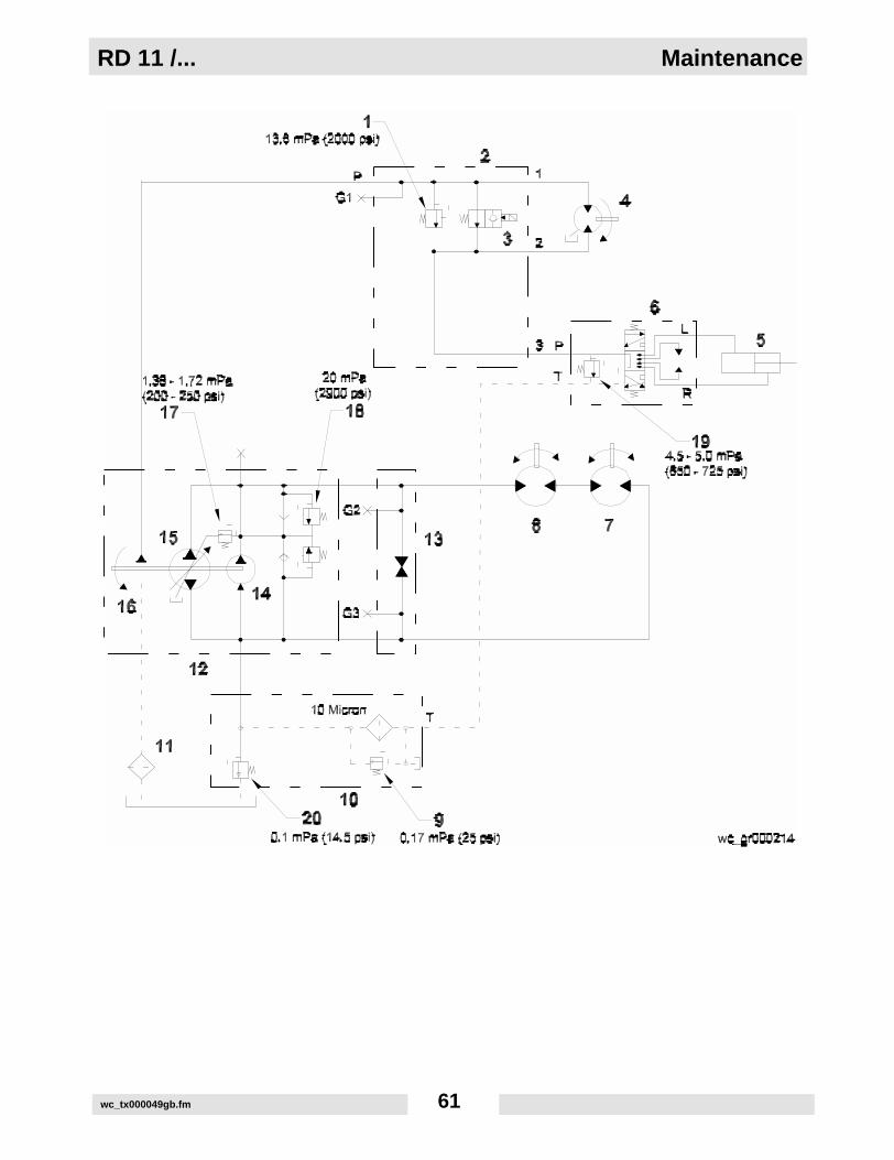
5.28 Hydraulic Schematic (RD11A / RD11V)See Graphic: wc_gr000214
Ref. Description Ref. Description
1. Exciter Relief Valve 11. Suction Filter
2. Manifold 12. Pump Assembly
3. Exciter Control Valve 13. Towing Valve
4. Exciter Motor 14. Charge Pump
5. Steering Cylinder 15. Drive Pump
6. Steering Valve 16. Exciter Pump
7. Rear Drive Motor 17. Charge Pressure Relief Valve
8. Front Drive Motor 18. Internal Drive Pump Relief Valves
9. Filter Bypass 19. Steering Relief Valve
10. Return Line Filter Assembly 20. Backpressure Valve
RD 11 /... Maintenance
wc_tx000049gb.fm 61

Maintenance RD 11 /...
wc_tx000049gb.fm 62
5.29 Hydraulic Diagram (RD11A / RD11V)
See Graphic: wc_gr000215
Ref. Description Ref. Description
1. Exciter Relief Valve 11. Suction Filter
2. Manifold 12. Pump Assembly
3. Exciter Control Valve 13. Towing Valve
4. Exciter Motor 14. Charge Pump
5. Steering Cylinder 15. Drive Pump
6. Steering Valve 16. Exciter Pump
7. Rear Drive Motor 17. Charge Pressure Relief Valve
8. Front Drive Motor 18. Internal Drive Pump Relief Valves
9. Filter Bypass 19. Steering Relief Valve
10. Return Line Filter Assembly 20. Backpressure Valve

RD 11 /... Maintenance
wc_tx000049gb.fm 63

Maintenance RD 11 /...
wc_tx000049gb.fm 64
5.30 Hydraulic Schematic (RD11AEC)
See Graphic: wc_gr000206
Ref. Description Ref. Description
1. Exciter Relief Valve 14. Charge Pump
2. Manifold 15. Drive Pump
3. Exciter Control Valve 16. Exciter Pump
4. Exciter Motor 17. Charge Pressure Relief Valve
5. Steering Cylinder 18. Internal Drive Pump Relief Valves
6. Steering Valve 19. Steering Relief Valve
7. Rear Drive Motor 20. Backpressure Valve
8. Front Drive Motor 21. Manual Override Valve
9. Filter Bypass 22. Brake Valve
10. Return Line Filter Assembly 23. Hand Pump
11. Suction Filter 24. Shuttle Valve
12. Pump Assembly 25. Pressure Reducing Valve
13. Pump Shunt Valve

RD 11 /... Maintenance
wc_tx000049gb.fm 65

Maintenance RD 11 /...
wc_tx000049gb.fm 66
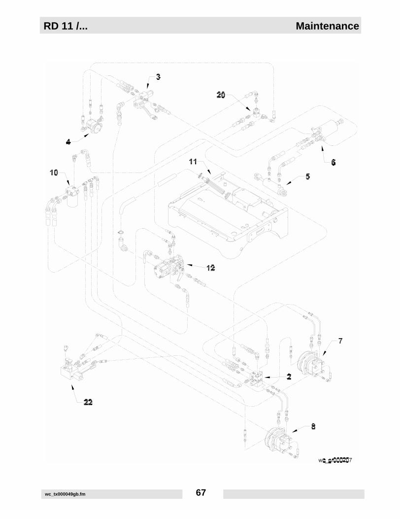
5.31 Hydraulic Diagram (RD11AEC)
See Graphic: wc_gr000207
Ref. Description Ref. Description
1. Exciter Relief Valve 14. Charge Pump
2. Manifold 15. Drive Pump
3. Exciter Control Valve 16. Exciter Pump
4. Exciter Motor 17. Charge Pressure Relief Valve
5. Steering Cylinder 18. Internal Drive Pump Relief Valves
6. Steering Valve 19. Steering Relief Valve
7. Rear Drive Motor 20. Backpressure Valve
8. Front Drive Motor 21. Manual Override Valve
9. Filter Bypass 22. Brake Valve
10. Return Line Filter Assembly 23. Hand Pump
11. Suction Filter 24. Shuttle Valve
12. Pump Assembly 25. Pressure Reducing Valve
13. Pump Shunt Valve
RD 11 /... Maintenance
wc_tx000049gb.fm 67

Maintenance RD 11 /...
wc_tx000049gb.fm 68
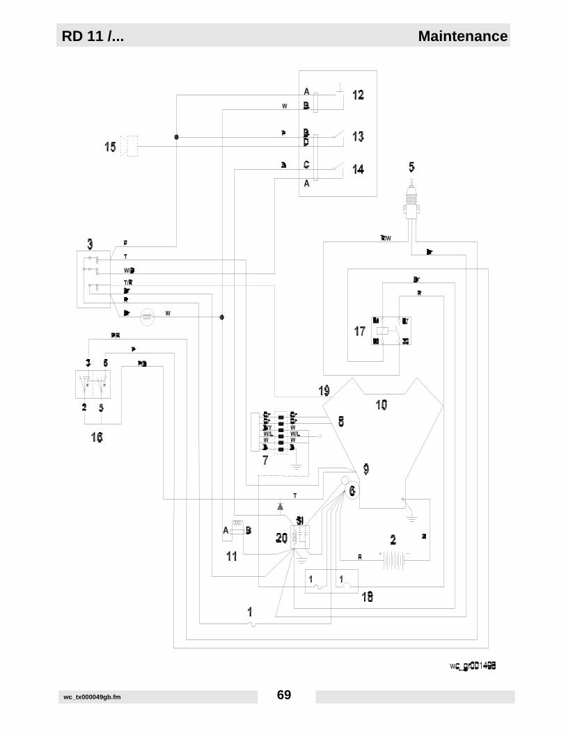
5.32 Electrical Schematic (RD11A) Revisions 116 & lower
See Graphic: wc_gr001498
Ref. Description Ref. Description
1. 20 Amp fuse 11. Exciter Manifold
2. Battery 12. Vibration Switch
3. Key Switch 13. Forward/Reverse Control
4. 14. Neutral Safety Switch
5. Throttle Solenoid 15. Backup Alarm (optional)
6. Starter 16. Throttle Switch
7. Regulator / Rectifier 17. 12VDC Relay
8. Alternator 18. 20 Amp Circuit Breaker
9. Anti-backfire 19. Magneto Kill
10. Engine 20. Starter Relay
Wire Colors
B Black R Red Y Yellow Or Orange
G Green T Tan Br Brown Pr Purple
L Blue V Violet Cl Clear Sh Shield
P Pink W White Gr Gray LL Light Blue
RD 11 /... Maintenance
wc_tx000049gb.fm 69

Maintenance RD 11 /...
wc_tx000049gb.fm 70
5.33 Electrical Schematic (RD11A) Revisions 117 & higher
See Graphic: wc_gr000210
Ref. Description Ref. Description
1. 20 Amp fuse 11. Exciter Manifold
2. Battery 12. Vibration Switch
3. Key Switch 13. Forward/Reverse Control
4. 14. Neutral Safety Switch
5. Throttle Solenoid 15. Backup Alarm (optional)
6. Starter 16. Throttle Switch
7. Regulator / Rectifier 17. 12VDC Relay
8. Alternator 18. 20 Amp Circuit Breaker
9. Anti-backfire 19. Magneto kill
10. Engine 20. Starter Relay
Wire Colors
B Black R Red Y Yellow Or Orange
G Green T Tan Br Brown Pr Purple
L Blue V Violet Cl Clear Sh Shield
P Pink W White Gr Gray LL Light Blue

RD 11 /... Maintenance
wc_tx000049gb.fm 71

Maintenance RD 11 /...
wc_tx000049gb.fm 72
5.34 Electrical Schematic (RD11V)
See Graphic: wc_gr000209
Ref. Description Ref. Description
1. 20 Amp fuse 11. Exciter Manifold
2. Battery 12. Vibration Switch
3. Key Switch 13. Forward/Reverse Control
4. 14. Neutral Safety Switch
5. Throttle Solenoid 15. Backup Alarm (optional)
6. Starter 16. Throttle Switch
7. Regulator / Rectifier 17. 12VDC Relay
8. Alternator 18. 20 Amp Circuit Breaker
9. Anti-backfire 19. Magneto Kill
10. Engine 20. Starter Relay
Wire Colors
B Black R Red Y Yellow Or Orange
G Green T Tan Br Brown Pr Purple
L Blue V Violet Cl Clear Sh Shield
P Pink W White Gr Gray LL Light Blue

RD 11 /... Maintenance
wc_tx000049gb.fm 73

Maintenance RD 11 /...
wc_tx000049gb.fm 74
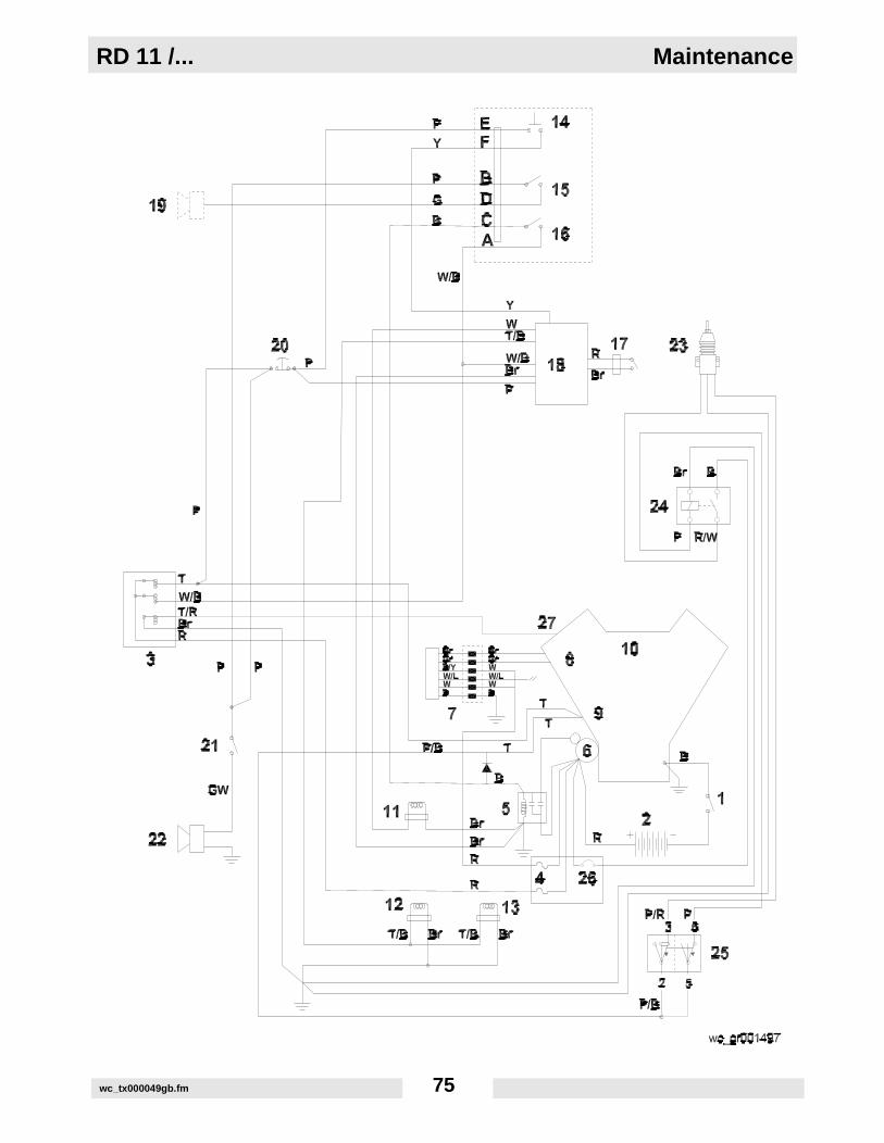
5.35 Electrical Schematic (RD11AEC) Revisions 125 & lower
See Graphic: wc_gr001497
Ref. Description Ref. Description
1. Battery Disconnect 15. Forward/Reverse Control
2. Battery 16. Neutral Safety Switch
3. Key Switch 17. Seat Switch
4. 20 Amp fuse 18. Seat Switch Delay and Neutral Start Module
5. Starter Relay 19. Backup Alarm (Optional)
6. Starter 20. Emergency Stop Pushbutton
7. Regulator / Rectifier 21. Horn Switch
8. Alternator 22. Horn
9. Anti-Backfire 23. Throttle Solenoid
10. Engine 24. 12VDC Relay
11. Exciter Manifold 25. Throttle Switch
12. Brake Manifold 26. 20 Amp Circuit Breaker
13. Brake Bypass (Towing Valve) 27. Magneto Kill
14. Vibration Switch
Wire Colors
B Black R Red Y Yellow Or Orange
G Green T Tan Br Brown Pr Purple
L Blue V Violet Cl Clear Sh Shield
P Pink W White Gr Gray LL Light Blue
RD 11 /... Maintenance
wc_tx000049gb.fm 75
Maintenance RD 11 /...
wc_tx000049gb.fm 76
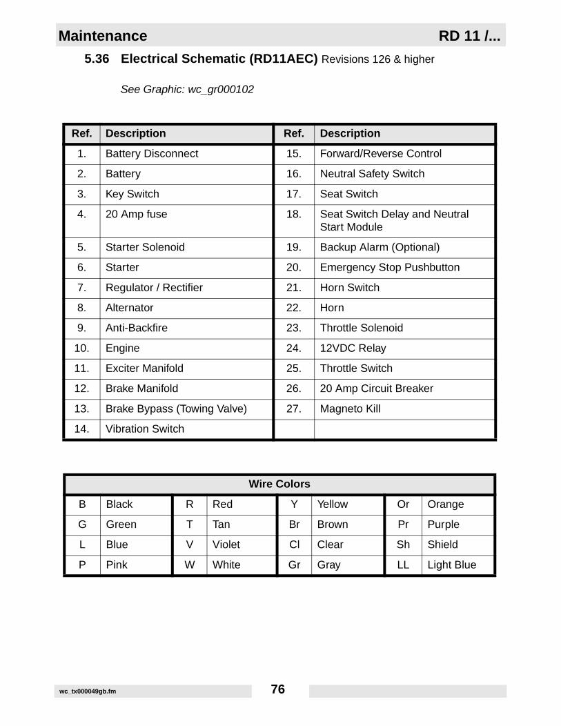
5.36 Electrical Schematic (RD11AEC) Revisions 126 & higher
See Graphic: wc_gr000102
Ref. Description Ref. Description
1. Battery Disconnect 15. Forward/Reverse Control
2. Battery 16. Neutral Safety Switch
3. Key Switch 17. Seat Switch
4. 20 Amp fuse 18. Seat Switch Delay and Neutral Start Module
5. Starter Solenoid 19. Backup Alarm (Optional)
6. Starter 20. Emergency Stop Pushbutton
7. Regulator / Rectifier 21. Horn Switch
8. Alternator 22. Horn
9. Anti-Backfire 23. Throttle Solenoid
10. Engine 24. 12VDC Relay
11. Exciter Manifold 25. Throttle Switch
12. Brake Manifold 26. 20 Amp Circuit Breaker
13. Brake Bypass (Towing Valve) 27. Magneto Kill
14. Vibration Switch
Wire Colors
B Black R Red Y Yellow Or Orange
G Green T Tan Br Brown Pr Purple
L Blue V Violet Cl Clear Sh Shield
P Pink W White Gr Gray LL Light Blue

RD 11 /... Maintenance
wc_tx000049gb.fm 77

Maintenance RD 11 /...
wc_tx000049gb.fm 78
5.37 Troubleshooting (RD11A / RD11V)
Problem / Symptom Reason / Remedy
ENGINE DOES NOT START
• Fuel tank empty.• Wrong type of fuel.• Old fuel. Drain tank, change fuel filter and fill with fresh fuel.• Fuel system not primed.• Fuel filter restricted or plugged. Replace filter.• Battery connections loose or corroded. Battery dead.• Air cleaner element plugged.• Starter motor defective.• Fuel solenoids on engine inoperative. • Starter relay inoperative.• Electrical connections loose or broken.• Key switch defective.
ENGINE STOPS BY ITSELF
• Fuel tank empty.• Fuel filter plugged.• Fuel lines broken or loose.• No spark.
NO VIBRATION • Defective switch or poor connection.• Solenoid on vibration valve damaged or disconnected.• Exciter assembly damaged.• Exciter motor coupling damaged or broken.• Exciter motor damaged.• Exciter pump damaged.
NO TRAVEL or TRAVEL ONLY IN ONE DIRECTION
• Pin sheared on control lever.• Control cable loose or broken.• Drive motor damaged.• Drive pump damaged.• Defective relief valve or valves.
NO STEERING • Steering cylinder damaged.• Steering unit damaged.• Steering relief valve stuck or damaged.• Articulation joint lockarm engaged.
RD 11 /... Maintenance
wc_tx000049gb.fm 79
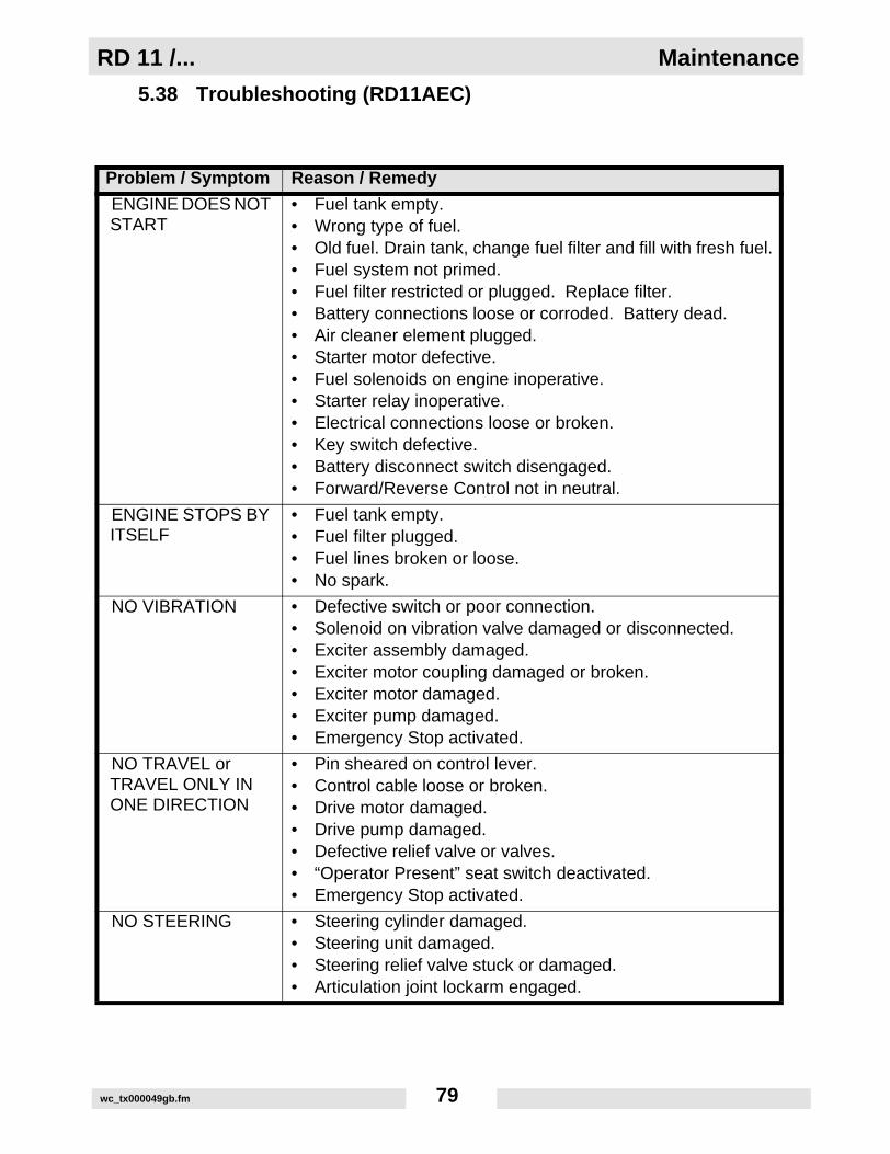
5.38 Troubleshooting (RD11AEC)
Problem / Symptom Reason / Remedy
ENGINE DOES NOT START
• Fuel tank empty.• Wrong type of fuel.• Old fuel. Drain tank, change fuel filter and fill with fresh fuel.• Fuel system not primed.• Fuel filter restricted or plugged. Replace filter.• Battery connections loose or corroded. Battery dead.• Air cleaner element plugged.• Starter motor defective.• Fuel solenoids on engine inoperative. • Starter relay inoperative.• Electrical connections loose or broken.• Key switch defective.• Battery disconnect switch disengaged.• Forward/Reverse Control not in neutral.
ENGINE STOPS BY ITSELF
• Fuel tank empty.• Fuel filter plugged.• Fuel lines broken or loose.• No spark.
NO VIBRATION • Defective switch or poor connection.• Solenoid on vibration valve damaged or disconnected.• Exciter assembly damaged.• Exciter motor coupling damaged or broken.• Exciter motor damaged.• Exciter pump damaged.• Emergency Stop activated.
NO TRAVEL or TRAVEL ONLY IN ONE DIRECTION
• Pin sheared on control lever.• Control cable loose or broken.• Drive motor damaged.• Drive pump damaged.• Defective relief valve or valves.• “Operator Present” seat switch deactivated.• Emergency Stop activated.
NO STEERING • Steering cylinder damaged.• Steering unit damaged.• Steering relief valve stuck or damaged.• Articulation joint lockarm engaged.

Maintenance RD 11 /...
wc_tx000049gb.fm 80

KE40246P1 6/9/05 3:14 PM Page 1
NOTICE OF COPYRIGHT PROTECTIONAEM Safety Manuals are protected as a copyrighted work withownership duly registered with the Copyright Office,Washington,D.C.Any reproduction, translation, decompiling or other use of anAEM Safety Manual, or portion thereof, or the creation of deriv-
ative works based on an AEM Safety Manual,without the prior writ-ten approval of AEM, is expressly prohibited. Copyright infringe-ment can result in civil and criminal sanctions, damages and otherpenalties being imposed.
Copyright © 1978 AEM (Association of Equipment Manufacturers)Former Copyright © CIMA (Construction Industry Manufacturer Association)
Revised 6/02, 9/04
SAFETY ALERT SYMBOLThis Safety Alert Symbol meansATTENTION is involved!
The Safety Alert Symbol identifies important safetymessages on machines, safety signs, in manuals, orelsewhere.When you see this symbol, be alert tothe possibility of personal injury or death. Followthe instructions in the safety message.
Why is SAFETY important to YOU?
3 BIG REASONS:• Accidents KILL or DISABLE• Accidents COST• Accidents CAN BE AVOIDED
KE40246P2 6/9/05 3:16 PM Page i

WORD OF EXPLANATION................................................................................ 2
FOREWORD.......................................................................................................... 4
A WORD TO THE USER ...................................................................................... 5
FOLLOW A SAFETY PROGRAM ...................................................................... 6
PREPARE FOR SAFE OPERATION.................................................................... 9
START SAFELY....................................................................................................15
WORK SAFELY .................................................................................................. 18
PARK & SHUTDOWN SAFELY ...................................................................... 23
LOAD & UNLOAD MACHINE SAFELY ........................................................ 25
TRANSPORTING SAFELY .............................................................................. 26
PERFORM MAINTENANCE SAFELY ............................................................ 28
SPECIAL OPERATING AND MAINTENANCE PRECAUTIONS................ 43
TEST YOUR KNOWLEDGE ............................................................................ 47
A FINAL WORD TO THE USER ...................................................................... 48
1
KE40246P2 6/9/05 3:16 PM Page 1
WORD OF EXPLANATION
The following is a partial list of reference material on safe operating practices:
U.S. Department of Labor publishes safety andhealth regulations and standards under theauthority of the Occupational Safety and Health Actfor the general construction and mining industries.Its address is: U.S. Department of Labor, 200Constitution Avenue, NW,Washington, DC 20210.
SAE - Society of Automotive Engineers, Inc., 400Commonwealth Drive,Warrendale, PA 15096,publishes a list, "Operator Precautions," SAE J153MAY, 1987.
Association of Equipment Manufacturers,111 East Wisconsin Avenue, Milwaukee,WI USA53202, publishes the Roller Compactor SafetyManual and other safety-related material.
2
KE40246P2 6/9/05 3:16 PM Page 2

3
This Safety Manual covers many different types ofroller compactors … including steel wheel rollers,vibratory rollers, rubber-tired rollers, segmentedpad/sheepsfoot soil compactors and landfill compactors.These may be either self-propelled ride-on, walk-behind or towed rollers.They may beused for the compaction of asphalt, soil, landfill orother materials. Excluded from coverage are vibratory plates and hand rammers.
Regardless of which machine you operate, it isYOUR responsibility to study and understand thisSafety Manual, and to see that a copy remainswith your machine.The manual begins with your“safety homework,” takes you step-by-stepthrough your working day, and ends withmaintenance operations.
Manufacturers produce machines with manybuilt-in safety features. Employers provideaccident prevention programs.Yet, the ultimateresponsibility to operate and maintain yourmachine with the skill, care and knowledgeessential for safety is YOURS.
Do not operate your machine until you have beentrained in the use of all operating controls andunderstand the handling characteristics of themachine.
REMEMBER — SAFETY … YOURS AND THAT OFTHOSE AROUND YOU … IS UP TO YOU!
WORD OF EXPLANATION
KE40246P2 6/9/05 3:16 PM Page 3
4
This safety manual is intended to point out some ofthe basic situations which may be encounteredduring the normal operation and maintenance ofyour machine, and to suggest possible ways ofdealing with these conditions.
Additional precautions may be necessary, dependingon application, machine type, configuration andattachments used, and conditions at the work-siteor in the maintenance area.The manufacturer has nodirect control over machine application, operation,inspection, lubrication or maintenance.Therefore, itis your responsibility to use good safe practices inthese areas.
The information provided in this manual supplementsthe specific information about your machine that iscontained in the manufacturer's manual(s). Otherinformation which may affect the safe operation ofyour machine may be contained on safety signs, or ininsurance requirements, employer's safety programs,safety codes, local, state/provincial and federal laws,rules and regulations.
If you do not understand any of this information, orif errors or contradictions seem to exist, consult withyour supervisor before operating your machine.
IMPORTANT: If you do not have themanufacturer's manual(s) for your particularmachine, get a replacement manual from youremployer, equipment dealer, or manufacturerof your machine. Keep this safety manual andthe manufacturer's manual(s) with yourmachine.
Unauthorized modifications of machines createhazards. Machines should not be modified or alteredunless prior approval is obtained from the manufacturer.
FOREWORD
KE40246P2 6/9/05 3:16 PM Page 4
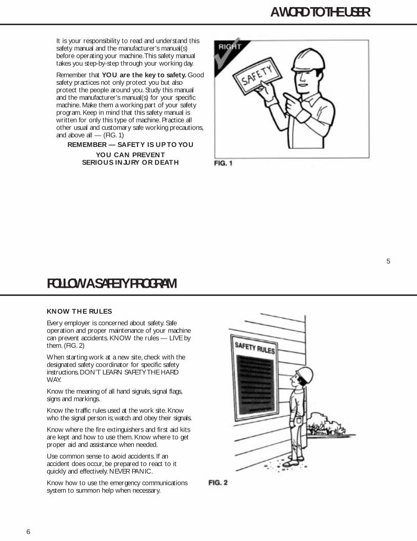
It is your responsibility to read and understand thissafety manual and the manufacturer's manual(s)before operating your machine.This safety manualtakes you step-by-step through your working day.
Remember that YOU are the key to safety. Goodsafety practices not only protect you but also protect the people around you. Study this manualand the manufacturer's manual(s) for your specificmachine. Make them a working part of your safetyprogram. Keep in mind that this safety manual iswritten for only this type of machine. Practice allother usual and customary safe working precautions,and above all — (FIG. 1)
REMEMBER — SAFETY IS UP TO YOU
YOU CAN PREVENTSERIOUS INJURY OR DEATH
5
A WORD TO THE USER
KE40246P2 6/9/05 3:16 PM Page 5
6
KNOW THE RULES
Every employer is concerned about safety. Safeoperation and proper maintenance of your machinecan prevent accidents. KNOW the rules — LIVE bythem. (FIG. 2)
When starting work at a new site, check with thedesignated safety coordinator for specific safetyinstructions. DON’T LEARN SAFETY THE HARDWAY.
Know the meaning of all hand signals, signal flags,signs and markings.
Know the traffic rules used at the work site. Knowwho the signal person is; watch and obey their signals.
Know where the fire extinguishers and first aid kitsare kept and how to use them. Know where to getproper aid and assistance when needed.
Use common sense to avoid accidents. If an accident does occur, be prepared to react to itquickly and effectively. NEVER PANIC.
Know how to use the emergency communicationssystem to summon help when necessary.
FOLLOW A SAFETY PROGRAM
KE40246P2 6/9/05 3:16 PM Page 6

7
KNOW WHAT IT IS?
Consult your supervisor for specific instructions ona job, and the personal safety equipment required.For instance, you may need:• Hard Hat• Safety Shoes• Eye Protection• Face Protection• Heavy Gloves• Reflector Vests• Hearing Protection• Respirators
Do not wear loose clothing or any accessory — flopping cuffs, untied shoelaces, dangling necktiesand scarves, rings, wrist watches, or other jewelry— that can catch on protruding or moving parts orcontrols. Long hair should be securely bound toprevent entanglement with moving parts. (FIG. 3)
FOLLOW A SAFETY PROGRAM
KE40246P2 6/9/05 3:16 PM Page 7
8
BE ALERT!
Know where to get assistance. Know how to use afirst aid kit and fire extinguisher or fire suppressionsystem. (FIG. 4)
BE AWARE!
Take advantage of training programs offered.
Safety programs require that one person at eachjobsite be assigned the overall responsibility andauthority for safety. Know who that person is,and COMMUNICATE.
Know what the jobsite rules are, and FOLLOW THERULES. Be safety conscious, responsible and reliable.Think about safety BEFORE something happens.
Report unsafe conditions to a supervisor immediately!
BE CAREFUL!
Human error is caused by many factors:carelessness, fatigue, overload, preoccupation,incompatibility between operator and the machine,drugs, and alcohol to name a few. Eliminate thesefactors BEFORE accidents occur. Damage to themachine can be fixed in a short period of time, butinjury, or death has a lasting effect.
FOR YOUR SAFETY AND SAFETY OFOTHERS, ENCOURAGE YOUR FELLOWWORKERS TO ACT SAFELY.
FOLLOW A SAFETY PROGRAM
KE40246P2 6/9/05 3:16 PM Page 8

LEARN TO BE SAFE
READ the operator’s manual. If one has not beenprovided, GET ONE AND STUDY IT BEFOREOPERATING THE MACHINE. If you have anyquestions contact the manufacturer.Know the positions and understand the functionsof all controls before attempting to operate amachine. Know the meaning of all identificationsymbols on your controls and gauges. (FIG. 5)Know the location of the emergency shut-downcontrol if the machine is so equipped.Know the capabilities and limitations of themachine … such as speed, breaking and steering.Know the operational and transport dimensionsof your machine to avoid inadvertently hittingsomething during operation or transporting.Carefully read and follow the instructions on allsafety signs on the machine. Keep safety signs ingood condition. Replace missing or damagedsafety signs.
9
PREPARE FOR SAFE OPERATION
NEVER operate a machine which is new to youwithout first being instructed in its proper operation.
CHECK IT OUT!
Always conduct a pre-shift inspection before operatingany machine. Know what safety devices your machineis equipped with … and see that each item is securelyin place and in operating condition. (FIG. 6)
For example:• Safety Blocks and Locks• Other Locking Devices• Lights• Alarms• Horn• Guards and Shields• Shut-Down Devices• First Aid Kit• Fire Extinguishers
KE40246P2 6/9/05 3:17 PM Page 9
TIRES
Inspect pneumatic tires (if so equipped) fordamage, wear, and proper inflation. Never operatewith over-inflated or under-inflated tires. (FIG. 7)
Check that all wheel lug nuts are present and tight.
NEVER START OR OPERATE A MACHINEKNOWN OR SUSPECTED TO BE DEFECTIVEOR MALFUNCTIONING.
10
PREPARE FOR SAFE OPERATION
KNOW YOUR MACHINE
Never operate a machine for which you are nottrained or qualified.
Familiarize yourself with pedals, controls andinstruments – their locations and function.
To handle controls without slipping, wipe themclean of oil and grease.
Remove tools, supplies and other materials fromthe working areas and machine walkways – andkeep these areas free of trash.
Make sure the items you do carry are not looseor in the way.
ARE REPAIRS MADE?
If your daily check uncovers any item that needsattention – repair, replacement, or adjustment –report it to your supervisor and tag the machineon the start switch and/or other appropriate,prominent location. A minor malfunction couldbe a sign of a more serious problem if themachine is operated.
KE40246P2 6/9/05 3:17 PM Page 10

FIRE PREVENTION
Never allow flammable fluids or materials tocontact hot surfaces.
Never refuel:• When engine is running• While smoking• Near open flames or sparks• In poorly ventilated area
Never overfill fuel tank or fluid reservoirs.Clean up spills immediately.
Replace fuel cap securely after filling.
Check for fuel, oil and hydraulic fluid leaks.Replace worn or damaged hoses/tubes.Afterrepairs are made, clean the machine before youoperate it.
Inspect electrical wiring for worn or damagedinsulation. Install new wiring if wires are damaged.
11
PREPARE FOR SAFE OPERATION
Because ether or other starting fluids are flammable,do not smoke when using them.Always follow theinstructions on the container and in the operator’smanual for your machine. (See page 19.)
Batteries produce explosive gases. Keep open flameor sparks away. See the manufacturer’s instructionswhen servicing the batteries, when using jumpercables or when using a battery charger. (See pages36 and 37.)
Remove all trash or debris from the machine. Makesure that oily rags or other flammable material arenot stored on the machine. (FIG. 8)
KE40246P2 6/9/05 3:17 PM Page 11
PREPARING TO ROAD THE MACHINE
Know what conditions you will likely encounter:• Insufficient clearances• Traffic congestion• Type of surface• Steep grades• Restricted visibility
Determine appropriate warnings to be used. (FIG. 9)Know whether you will need to be escorted.
If the machine is to travel on a road or highway,refer to the manufacturer’s manual(s) for instructions.Become familiar with local laws and ordinances affectingdriving on highways. Use “slow moving vehicle” emblem.Make sure flags, lights, and warning signs are in place.
Select the proper gear before negotiating steep grades. (FIG. 10)
12
PREPARE FOR SAFE OPERATION
KE40246P2 6/9/05 3:17 PM Page 12

Before starting, carefully inspect your machine forany evidence of physical damage such as cracking,bending or deformation of plates or welds. Check forcracking or flaking of paint, which may indicate anexcessive strain or dangerous crack in the materialbelow. Check for loose, broken or missing parts suchas Roll-Over Protective Structure (ROPS) supportbrackets, vibration isolators, and nuts and bolts. Ifpotentially serious problems are found, do notoperate the machine until appropriate repairs arecompleted.
Check the level of all fluids … brake, transmission,power steering, engine coolant, hydraulic system, andothers. Fill low reservoirs only to the proper level.
Check the various systems (hydraulic, cooling, etc.)for leaks. (FIG. 11) Inspect all plugs, filler caps andfittings for tell-tale signs of leaks.ALWAYS use aflashlight or shielded trouble light when checking …Never an open flame. Repair any leaks, or have themrepaired by authorized service personnel. (See pages28 through 42 for additional service cautions.)
Check the fuel level and, if low, fill the tank with theproper grade of clean fuel before extended operation(following the instructions on page 34).
A stalled or faltering engine can result in a realhazard when operating on grades, in traffic or inheavily congested areas.
NEVER smoke when checking fuel level or refueling.
13
PREPARE FOR SAFE OPERATION
KE40246P2 6/9/05 3:17 PM Page 13
BE SURE THE WORK AREA IS SAFE
Before beginning operation, thoroughly check thearea for any unusual conditions that could bedangerous. (FIG. 12) Check for hidden holes,drop-offs or overhead obstacles that could bedangerous. Check the clearance under overheadpower and phone lines. LOOK UP AS WELL ASDOWN.
Be observant of other workmen, bystanders andother machines in the area. Be especially careful iftrenches, lightpoles, tiles, buildings, etc. are withinthe effective range of a vibratory compactor.IMPROPER OPERATION COULD RESULT INDAMAGE OR INJURY.
Remember, the danger of sliding and/or tipping onsteep slopes is always present … regardless ofhow heavy or “stable” your machine may appear tobe.When operating under these conditions, theuse of ROPS and seat belts reduces the hazard tooperating personnel.
14
PREPARE FOR SAFE OPERATION
FIG. 12
KE40246P2 6/9/05 3:17 PM Page 14

Walk around your machine once more just prior tomounting it – checking for people and objects thatmight be in the way – then MOUNT PROPERLYUSING STEPS AND HANDHOLDS PROVIDED.
Always use seat belts if your machine is equippedwith a ROPS.
Just before starting, check all controls … such asforward and reverse, steering, transmission andthrottle to be sure they are in the correct start-upposition. (FIG. 13) The parking brake should beapplied during the start-up operation.
Check for proper functioning of all operating andshut-down controls.
START CORRECTLY
Know the PROPER starting procedure for yourmachine. Follow the manufacturer’s operationmanual … to the letter.
Then, start your engine.
15
START SAFELY
KE40246P2 6/9/05 3:17 PM Page 15
IMMEDIATELY AFTER STARTING THE ENGINE …
• Observe gauges, instruments, and warning lights toensure that they are functioning and their readingsare within the normal operating range. (FIG. 14)
• Be sure work area is safe for test operation of thevarious controls and attachments.
• Operate all controls: make certain they operate properly, and “feel” right.Accustom yourself to the“feel” of your machine.
• Listen for any unusual noises; smell for any unusualodors; look for any signs of trouble.
• Check all warning and safety devices and indicators.
• If safety-related defects or malfunctions are detected, shut down the machine. Correct it, or notify your supervisor. DO NOT OPERATE UNTIL CORRECTED.
Check operation of service and parking brakes onlevel ground if possible.
Check service brakes (including hydrostatic brakes,if so equipped) in both forward and reverseoperation (FIG. 15) ACCORDING TO THEMANUFACTURERS INSTRUCTIONS.
If an unsafe condition cannot be remedied immediately, notify your supervisor and tag themachine on the start switch and/or other appropriate, prominent location. (See page 28 forLockout/Tagout procedure.) No machine should be operated if any part is not in safe operating condition. Make certain that any unsafecondition has been satisfactorily remedied.
16
START SAFELY
KE40246P2 6/9/05 3:17 PM Page 16

COLD WEATHER OPERATION
Consult the engine manufacturer’s operation manualfor proper cold weather starting procedure.
When using cold weather starting aids, be sure tofollow the engine manufacturer’s instructions.(FIG. 16)
After starting, operate all systems slowly and gentlyuntil properly warmed up.
BOOSTER CABLE INSTRUCTIONS
1. Connect positive (+) cable to positive post ofdischarged battery.
2. Connect other end of same cable to same markedpost of booster battery.
3. Connect negative (-) cable to other post of booster battery.
4. Make final connection on stalled vehicle away frombattery, either on vehicle frame or engine block.
5. Start vehicle and remove cables in reverse order of connection.
17
START SAFELY
KE40246P2 6/9/05 3:17 PM Page 17
REMEMBER THESE RULES
When roading or operating a machine, always stayin the operator’s station. NEVER mount or dismounta machine that is moving. Maintain control of yourmachine at all times.
ALWAYS operate your machine slowly until fullyfamiliarized with it’s operation.
Constantly check your total work area forpotential hazards.
Never JUMP on or off your machine. Use the stepsand handholds provided to mount or dismountsafely. Maintain three point contact when mountingor dismounting.(FIG. 17)
• Never use controls or levers as hand holds.• Never jump off the machine.
Look, listen and smell for possible malfunctions. Ifmalfunctioning controls or erratic operation aredetected, correct or report them immediately.DO NOT OPERATE THE MACHINE UNTILCORRECTED.
Prevent asphyxiation. If you must operate in abuilding or other enclosed area, or if yourmachine is equipped with an enclosed cab, be cer-tain there is adequate ventilation.
Use extra care when refueling. (See page 34 forspecial precautions.)
18
WORK SAFELY
KE40246P2 6/9/05 3:17 PM Page 18
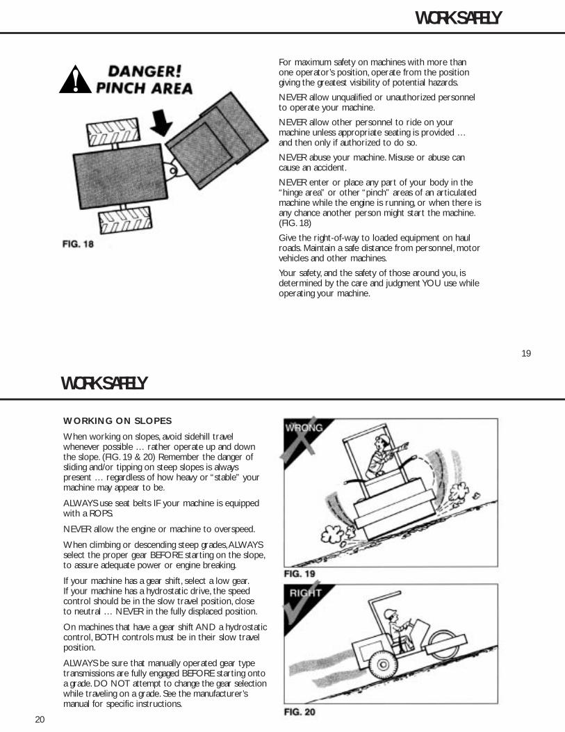
For maximum safety on machines with more thanone operator’s position, operate from the positiongiving the greatest visibility of potential hazards.
NEVER allow unqualified or unauthorized personnelto operate your machine.
NEVER allow other personnel to ride on yourmachine unless appropriate seating is provided …and then only if authorized to do so.
NEVER abuse your machine. Misuse or abuse cancause an accident.
NEVER enter or place any part of your body in the“hinge area” or other “pinch” areas of an articulatedmachine while the engine is running, or when there isany chance another person might start the machine.(FIG. 18)
Give the right-of-way to loaded equipment on haulroads. Maintain a safe distance from personnel, motorvehicles and other machines.
Your safety, and the safety of those around you, isdetermined by the care and judgment YOU use whileoperating your machine.
19
WORK SAFELY
KE40246P2 6/9/05 3:17 PM Page 19
20
WORKING ON SLOPES
When working on slopes, avoid sidehill travel whenever possible … rather operate up and downthe slope. (FIG. 19 & 20) Remember the danger ofsliding and/or tipping on steep slopes is always present … regardless of how heavy or “stable” yourmachine may appear to be.
ALWAYS use seat belts IF your machine is equippedwith a ROPS.
NEVER allow the engine or machine to overspeed.
When climbing or descending steep grades,ALWAYSselect the proper gear BEFORE starting on the slope,to assure adequate power or engine breaking.
If your machine has a gear shift, select a low gear.If your machine has a hydrostatic drive, the speedcontrol should be in the slow travel position, closeto neutral … NEVER in the fully displaced position.
On machines that have a gear shift AND a hydrostaticcontrol, BOTH controls must be in their slow travelposition.
ALWAYS be sure that manually operated gear typetransmissions are fully engaged BEFORE starting ontoa grade. DO NOT attempt to change the gear selectionwhile traveling on a grade. See the manufacturer’smanual for specific instructions.
WORK SAFELY
KE40246P2 6/9/05 3:17 PM Page 20

21
Avoid operating your machine too close to anoverhang, deep ditch or hole. If your machineinadvertently gets close to a tipping conditionor drop-off, STOP and get off the machineafter applying the parking brake … plan yourmoves carefully before proceeding. Reversal isoften the best move.
Be alert to potential caving edges, falling rocksand slides.
Check for overhead obstacles that could bedangerous. LOOK UP AS WELL AS DOWN.(FIG. 21)
Be alert to obstacles and excessively roughterrain. Back away from them and go around.
Always travel slowly over rough terrain andhillsides. Maintain a speed consistent with theworking conditions.
WORK SAFELY
KE40246P2 6/9/05 3:17 PM Page 21
22
When traveling on a public road, obey all trafficregulations and be sure that the proper clearanceflags, lights and warning signs … such as the “slowmoving vehicle” emblem … are used. (FIG. 22)
NEVER speed … and NEVER coast in neutral.
When roading the machine know your approxi-mate stopping distance at any given speed.
NEVER turn corners at excessively high speeds.(FIG. 23)
Always look in all directions before reversingyour direction of travel.
Use EXTRA caution when working in closequarters or when traveling through congestedareas. Courtesy pays off.
WORK SAFELY
KE40246P2 6/9/05 3:17 PM Page 22
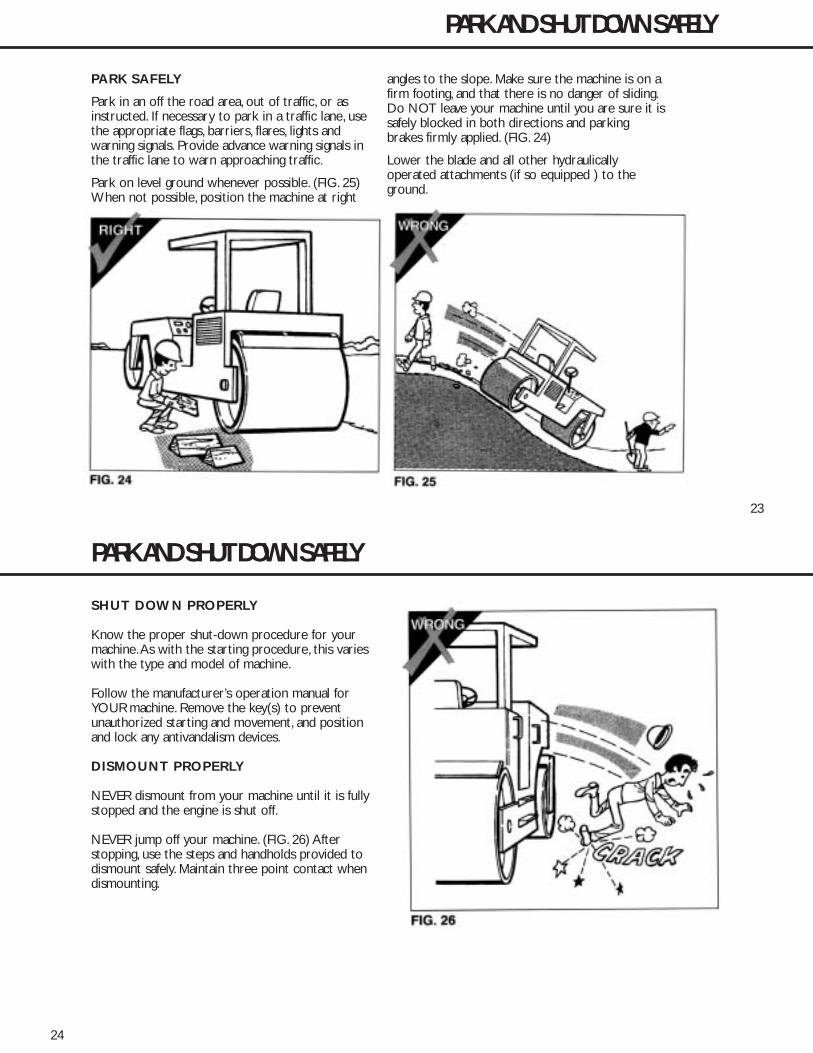
23
PARK SAFELY
Park in an off the road area, out of traffic, or asinstructed. If necessary to park in a traffic lane, usethe appropriate flags, barriers, flares, lights andwarning signals. Provide advance warning signals inthe traffic lane to warn approaching traffic.
Park on level ground whenever possible. (FIG. 25)When not possible, position the machine at right
angles to the slope. Make sure the machine is on afirm footing, and that there is no danger of sliding.Do NOT leave your machine until you are sure it issafely blocked in both directions and parkingbrakes firmly applied. (FIG. 24)
Lower the blade and all other hydraulicallyoperated attachments (if so equipped ) to theground.
PARK AND SHUT DOWN SAFELY
KE40246P2 6/9/05 3:17 PM Page 23
24
SHUT DOWN PROPERLY
Know the proper shut-down procedure for yourmachine.As with the starting procedure, this varieswith the type and model of machine.
Follow the manufacturer’s operation manual forYOUR machine. Remove the key(s) to preventunauthorized starting and movement, and positionand lock any antivandalism devices.
DISMOUNT PROPERLY
NEVER dismount from your machine until it is fullystopped and the engine is shut off.
NEVER jump off your machine. (FIG. 26) Afterstopping, use the steps and handholds provided todismount safely. Maintain three point contact whendismounting.
PARK AND SHUT DOWN SAFELY
KE40246P2 6/9/05 3:17 PM Page 24
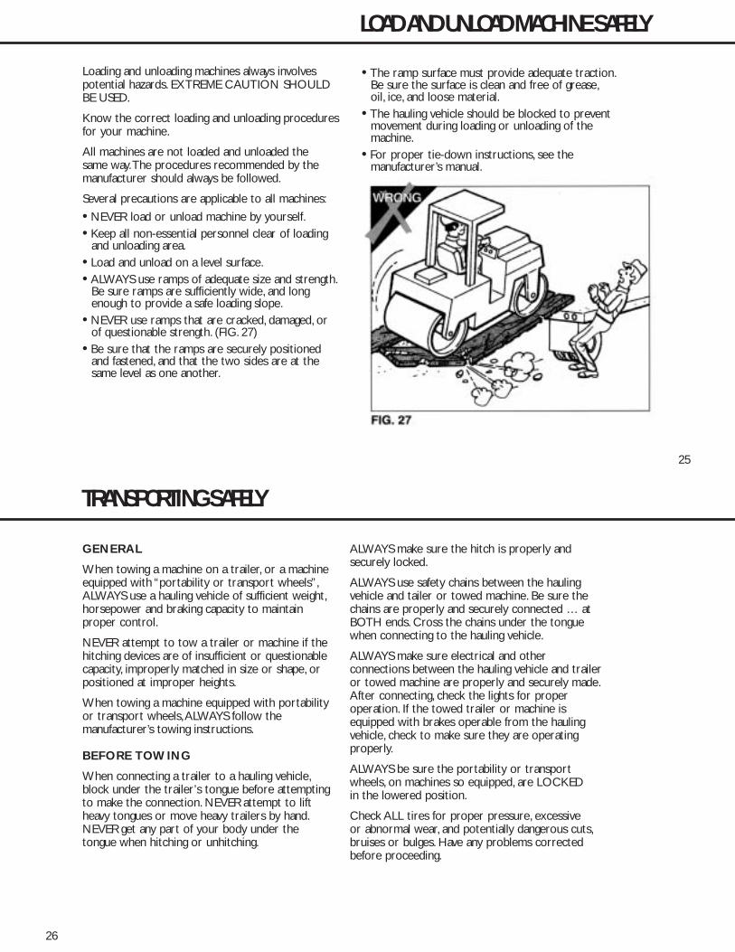
25
Loading and unloading machines always involvespotential hazards. EXTREME CAUTION SHOULDBE USED.
Know the correct loading and unloading proceduresfor your machine.
All machines are not loaded and unloaded thesame way.The procedures recommended by themanufacturer should always be followed.
Several precautions are applicable to all machines:
• NEVER load or unload machine by yourself.• Keep all non-essential personnel clear of loading
and unloading area.• Load and unload on a level surface.• ALWAYS use ramps of adequate size and strength.
Be sure ramps are sufficiently wide, and long enough to provide a safe loading slope.
• NEVER use ramps that are cracked, damaged, or of questionable strength. (FIG. 27)
• Be sure that the ramps are securely positioned and fastened, and that the two sides are at the same level as one another.
• The ramp surface must provide adequate traction.Be sure the surface is clean and free of grease,oil, ice, and loose material.
• The hauling vehicle should be blocked to prevent movement during loading or unloading of the machine.
• For proper tie-down instructions, see the manufacturer’s manual.
LOAD AND UNLOAD MACHINE SAFELY
KE40246P2 6/9/05 3:17 PM Page 25
26
GENERAL
When towing a machine on a trailer, or a machineequipped with “portability or transport wheels”,ALWAYS use a hauling vehicle of sufficient weight,horsepower and braking capacity to maintainproper control.
NEVER attempt to tow a trailer or machine if thehitching devices are of insufficient or questionablecapacity, improperly matched in size or shape, orpositioned at improper heights.
When towing a machine equipped with portabilityor transport wheels,ALWAYS follow themanufacturer’s towing instructions.
BEFORE TOWING
When connecting a trailer to a hauling vehicle,block under the trailer’s tongue before attemptingto make the connection. NEVER attempt to liftheavy tongues or move heavy trailers by hand.NEVER get any part of your body under thetongue when hitching or unhitching.
ALWAYS make sure the hitch is properly andsecurely locked.
ALWAYS use safety chains between the haulingvehicle and tailer or towed machine. Be sure thechains are properly and securely connected … atBOTH ends. Cross the chains under the tonguewhen connecting to the hauling vehicle.
ALWAYS make sure electrical and otherconnections between the hauling vehicle and traileror towed machine are properly and securely made.After connecting, check the lights for properoperation. If the towed trailer or machine isequipped with brakes operable from the haulingvehicle, check to make sure they are operatingproperly.
ALWAYS be sure the portability or transportwheels, on machines so equipped, are LOCKEDin the lowered position.
Check ALL tires for proper pressure, excessiveor abnormal wear, and potentially dangerous cuts,bruises or bulges. Have any problems correctedbefore proceeding.
TRANSPORTING SAFELY
KE40246P2 6/9/05 3:17 PM Page 26

27
TOWING
ALWAYS use EXTRA care when towing a trailer ormachine… when maneuvering in tight places, when backing(visibility is reduced, and jackknifing must be avoided), andwhen towing on steep grades.
Know and obey all local, state and federal laws and regulations.
NEVER travel at speeds above those recommended bythe manufacturer.
NEVER allow anyone to ride on a trailer or towedmachine. (FIG. 28)
When necessary to disconnect and park a trailer ortowed machine,ALWAYS select a location that is leveland, if possible, one where children are unlikely to bepresent. BEFORE disconnecting a trailer, chock the frontAND rear of the wheels, and block under the tongue.
See pages 23 through 24 for parking, shut-downprocedures and roading machine for transport.
TRANSPORTING SAFELY
KE40246P2 6/9/05 3:18 PM Page 27
28
GENERAL
Maintenance work can be hazardous if not done ina careful manner. All personnel should realize thehazards and strictly follow safe practices.
NEVER perform any work on the equipment unlessauthorized to do so. (FIG. 29) Before performing anymaintenance or repair work, consult the InstructionManual. Follow the manufacturer’s recommendedprocedures.
BEFORE any maintenance work is begun, reviewLOCKOUT/TAGOUT procedures. LOCKOUTcontrols and/or energy source and place a warninglabel to alert workers of shutdown.
PRIOR to removal of LOCKOUT/TAGOUT, theequipment must be fully operational and all personnelaccounted for. Except in cases of emergency, theremoval of the LOCKOUT/ TAGOUT should be doneby the initiating person prior to the return to start-up.
BEFORE doing any major work, or work on theelectrical system, disconnect the batteries.
REPLACE all missing or broken guards and panels.
USE proper nonflammable cleaning solvents. Followsolvent manufacturer’s instructions.
ALWAYS remove all flammable materials in thevicinity of welding and/or burning operations.
PERFORM MAINTENANCE SAFELY
BURNING OR WELDING in the vicinity of acousticalmaterial may release hazardous fumes.
KE40246P3 6/9/05 3:19 PM Page 28

29
PERFORM MAINTENANCE SAFELY
CLOTHING AND PERSONAL PROTECTIVE ITEMS
Keep hands and clothing well away from engine fan and moving parts while engine is running.
ALWAYS wear appropriate safety glasses, goggles or face shield when working. (FIG. 30) Proper eyeprotection can keep flying particles from grinding,drilling or hammering operations, or fluids such asfuel, solvents, lubricants and brake fluids, fromdamaging your eyes. Normal glasses do NOTprovide adequate protection.
ALWAYS wear a hard hat and safety shoes. (FIG. 30)ALWAYS wear hearing protectors when exposed tohigh noise levels for extended periods.ALWAYS weara respirator when painting or exposed to dustyconditions. ALWAYS keep your pockets free ofloose objects which can fall out and drop into
machinery. (FIG. 31) Heavy gloves should be wornfor many operations.
EXHAUST FUMES
Engine exhaust fumes can cause sickness or death.If it is necessary to run an engine in an enclosedarea, use an exhaust pipe extension. If you do nothave an exhaust pipe extension, be positive the areais adequately ventilated. (FIG. 32)
HEAVY PARTS
HEAVY PARTS
Handle tools and heavy parts sensibly – with regardfor yourself and other persons. Lower items – don’tthrow or drop them.
ALWAYS use proper hoisting equipment for liftingheavy loads.
KE40246P3 6/9/05 3:19 PM Page 29
30
• Keep machine in proper adjustment at all times.Serious injury could result if adjustments are neglected.
• Whenever possible,AVOID working on a machine with the engine running. If the engine must be run to make checks or adjustments, put the transmissionin neutral, set the parking brake and chock the drum and wheels securely ... front and rear ... to prevent movement in either direction.
• Personnel can be caught by moving parts when the guards are removed for access in making repairs.A repair or maintenance job is not complete until guards, plates and other safety devices have been replaced.
• NEVER put your fingers in open gears or reach through the spokes of a gear.
• Before working on the fuel system, close the fuel shut-off valve. NEVER smoke or use open flames near the machine while working on the fuel system.
• Remove and store all tools before resuming operation.
• Before working in the pivot or “pinch” area of an articulated machine, securely attach the steering frame lock to prevent the machine from turning.(FIG. 33) Enter this area only when necessary.
• Connect any other safety locks provided before proceeding with the work.
PERFORM MAINTENANCE SAFELY
KE40246P3 6/9/05 3:19 PM Page 30

31
Before beginning welding or burning operations, drainfuel lines and tank and move all flammable material to asafe distance, and be certain a fire extinguisher is readilyavailable.When welding fuel tanks, either gasoline ORdiesel,ALWAYS drain the tank, fill with water, and leavecap off during the welding operation.
All guards, plates and other safety devices mustbe properly replaced before the machine isreturned to service or serious injury to you or otherpersonnel may result.
AVOID burning or welding near acoustical materialwhenever possible, as hazardous fumes may bereleased. If unavoidable, make sure the area is adequatelyventilated, and that a fire extinguisher is ready available.
ALWAYS use authorized replacement parts that meetthe machine manufacturer’s specifications.
JACKING AND BLOCKING
ALWAYS lower all movable attachments to the groundor to their lowest position before servicing a machine.
If a machine must be raised for servicing or repairs,ALWAYS block the machine securely. Use axle stands orother rigid supports of ample capacity. NEVER rely solelyon the jacks for support. If necessary to work under amachine, be absolutely certain it is adequately supported.(FIG. 34)
WARNING: Never use concrete blocks for supports.They can collapse under even light loads.
When jacking up a machine, use a SUITABLE jack,placed in the proper position, on a solid foundation.
Before working on a machine, chock the drum andwheels securely … front and rear … in such a manneras to prevent movement in EITHER direction. Securelyattach the steering frame lock to prevent the machinefrom turning.
PERFORM MAINTENANCE SAFELY
KE40246P3 6/9/05 3:19 PM Page 31
32
FIRE PREVENTION
Whenever possible use a nonflammable solvent toclean parts. Do not use gasoline or other fluids thatgive off harmful vapors.
If flammable fluids, such as diesel fuel, must be used,extinguish open flames or sparks and do not smoke.
Store dangerous fluids in a suitable place, in approvedcontainers which are clearly marked. NEVER smokein areas where flammable fluids are used or stored.(FIG. 35)
Use proper nonflammable cleaning solvents. Followsolvent manufacturer’s instructions for use.
Always remove all flammable material in the vicinityof welding and/or burning operations.
ALWAYS keep the floor in the work area clean anddry. Oily, greasy floors can easily lead to falls. Wetspots, especially near electrical equipment, can behazardous. (FIG. 35)
Know where fire extinguishers are kept – how theyoperate – and for what type of fire they are intended.
Check readiness of any fire detectors and firesuppression systems.
PERFORM MAINTENANCE SAFELY
KE40246P3 6/9/05 3:19 PM Page 32

33
FIRE PREVENTION CHECKLIST (FIG. 36)
• Remove debris such as rags, coal dust, oil, leaves,pine needles.
• Check and repair fuel and hydraulic leaks.
• Check and repair damaged wiring.
• Prevent hose and electrical wire harness abrasion.
• Tighten loose clamps and fittings.
• Secure loose wiring.
• Make sure guards and protective covers are in place.
• Make sure fire extinguisher is available and operable.
PERFORM MAINTENANCE SAFELY
KE40246P3 6/9/05 3:19 PM Page 33
34
REFUELING (FIG. 37)
Precautions
When refueling, the following precautions must be followed:
• Add proper type and grade of fuel only when machine is not running and machine is parked with no one in the cab.
• Fuel in a well-ventilated area.
• Turn off all electrical switches.
• Turn off cab heaters.
• Open lights, lighted smoking materials, flames, or spark producing devices shall be kept at a safe distance while refueling.
• Keep fuel nozzle in contact with tank being filled,or provide a ground to prevent static sparks from igniting fuel.
• Do not spill fuel on hot surfaces.
• Any spillage shall be cleaned immediately.
• Do not start engine until fuel cap is secured to the fuel tank and people are clear of the machine.
• ALWAYS make sure fuel, oil, hydraulic fluid and water are added to their proper tanks.
PERFORM MAINTENANCE SAFELY
KE40246P3 6/9/05 3:19 PM Page 34

35
SERVICING COOLING SYSTEM
When checking coolant level:• Stop the engine and let the engine and radiator
cool before checking. (FIG. 38)
If an overheated engine requires a shutdown:• Wait for the radiator to cool. The hot
pressurized coolant can cause burn injuries. Neveradd coolant to an overheated system.
• Overheating is a symptom of trouble. Stop the engine and have the trouble corrected before serious damage occurs.
• If it is necessary to check an overheated engine use a heavy cloth, gloves, heavy clothing and safety glasses or goggles to protect yourself. Stand to the side, turn your face away, and slightly loosen the cap.Wait until the sound stops before removing the cap.
PERFORM MAINTENANCE SAFELY
KE40246P3 6/9/05 3:19 PM Page 35
36
SERVICING BATTERIES
Always wear safety glasses and gloves whenworking with batteries.
Before removing a battery, turn off all electricalequipment, then disconnect the negative (-)battery cable first. Before installing a battery,turn off all electrical equipment, then connectthe positive (+) battery cable first.
To prevent sparking at the posts when usinga battery charger, always turn the charger off ordisconnect it from its power source beforeconnecting or disconnecting charger leads tobattery posts. Caps on all cells should be lefton and the vent caps would be covered witha wet cloth.
Do not short across the battery terminals.The spark could ignite the gases.
BOOSTER CABLE INSTRUCTIONS (FIG.39)
1.Connect positive (+) cable to positive post of discharged battery.
2.Connect other end of same cable to same marked post of booster battery.
3.Connect negative (-) cable to other post of booster battery.
4.Make final connection on stalled vehicle away from battery, either on vehicle frame or engine block.
5.Start vehicle and remove cables in reverse order of connection.
PERFORM MAINTENANCE SAFELY
KE40246P3 6/9/05 3:19 PM Page 36
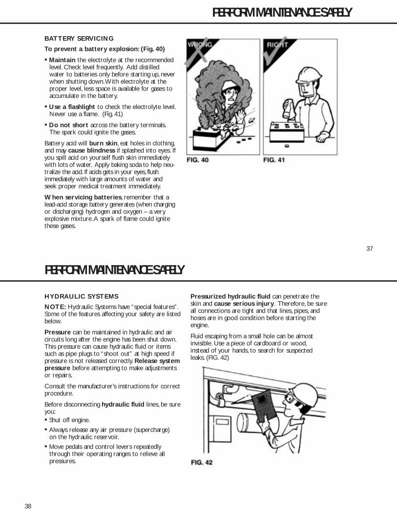
37
BATTERY SERVICING
To prevent a battery explosion: (Fig. 40)
• Maintain the electrolyte at the recommended level. Check level frequently. Add distilled water to batteries only before starting up, neverwhen shutting down.With electrolyte at the proper level, less space is available for gases toaccumulate in the battery.
• Use a flashlight to check the electrolyte level.Never use a flame. (Fig. 41)
• Do not short across the battery terminals.The spark could ignite the gases.
Battery acid will burn skin, eat holes in clothing,and may cause blindness if splashed into eyes. Ifyou spill acid on yourself flush skin immediatelywith lots of water. Apply baking soda to help neu-tralize the acid. If acids gets in your eyes, flushimmediately with large amounts of water andseek proper medical treatment immediately.
When servicing batteries, remember that alead-acid storage battery generates (when chargingor discharging) hydrogen and oxygen – a veryexplosive mixture.A spark of flame could ignitethese gases.
PERFORM MAINTENANCE SAFELY
KE40246P3 6/9/05 3:19 PM Page 37
38
HYDRAULIC SYSTEMS
NOTE: Hydraulic Systems have “special features”.Some of the features affecting your safety are listedbelow.
Pressure can be maintained in hydraulic and aircircuits long after the engine has been shut down.This pressure can cause hydraulic fluid or itemssuch as pipe plugs to “shoot out” at high speed ifpressure is not released correctly. Release systempressure before attempting to make adjustmentsor repairs.
Consult the manufacturer’s instructions for correctprocedure.
Before disconnecting hydraulic fluid lines, be sureyou:• Shut off engine.
• Always release any air pressure (supercharge) on the hydraulic reservoir.
• Move pedals and control levers repeatedly through their operating ranges to relieve all pressures.
Pressurized hydraulic fluid can penetrate theskin and cause serious injury. Therefore, be sureall connections are tight and that lines, pipes, andhoses are in good condition before starting theengine.
Fluid escaping from a small hole can be almostinvisible. Use a piece of cardboard or wood,instead of your hands, to search for suspectedleaks. (FIG. 42)
PERFORM MAINTENANCE SAFELY
KE40246P3 6/9/05 3:19 PM Page 38
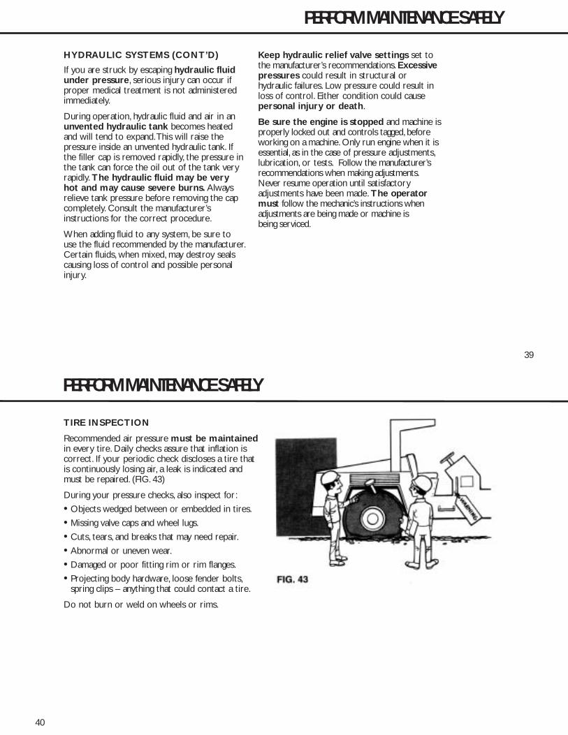
39
HYDRAULIC SYSTEMS (CONT’D)
If you are struck by escaping hydraulic fluidunder pressure, serious injury can occur ifproper medical treatment is not administeredimmediately.
During operation, hydraulic fluid and air in anunvented hydraulic tank becomes heatedand will tend to expand.This will raise thepressure inside an unvented hydraulic tank. Ifthe filler cap is removed rapidly, the pressure inthe tank can force the oil out of the tank veryrapidly. The hydraulic fluid may be veryhot and may cause severe burns. Alwaysrelieve tank pressure before removing the capcompletely. Consult the manufacturer’sinstructions for the correct procedure.
When adding fluid to any system, be sure touse the fluid recommended by the manufacturer.Certain fluids, when mixed, may destroy sealscausing loss of control and possible personalinjury.
Keep hydraulic relief valve settings set tothe manufacturer’s recommendations. Excessivepressures could result in structural orhydraulic failures. Low pressure could result inloss of control. Either condition could causepersonal injury or death.
Be sure the engine is stopped and machine isproperly locked out and controls tagged, beforeworking on a machine. Only run engine when it isessential, as in the case of pressure adjustments,lubrication, or tests. Follow the manufacturer’srecommendations when making adjustments.Never resume operation until satisfactoryadjustments have been made. The operatormust follow the mechanic’s instructions whenadjustments are being made or machine isbeing serviced.
PERFORM MAINTENANCE SAFELY
KE40246P3 6/9/05 3:19 PM Page 39
40
TIRE INSPECTION
Recommended air pressure must be maintainedin every tire. Daily checks assure that inflation iscorrect. If your periodic check discloses a tire thatis continuously losing air, a leak is indicated andmust be repaired. (FIG. 43)
During your pressure checks, also inspect for:
• Objects wedged between or embedded in tires.
• Missing valve caps and wheel lugs.
• Cuts, tears, and breaks that may need repair.
• Abnormal or uneven wear.
• Damaged or poor fitting rim or rim flanges.
• Projecting body hardware, loose fender bolts,spring clips – anything that could contact a tire.
Do not burn or weld on wheels or rims.
PERFORM MAINTENANCE SAFELY
KE40246P3 6/9/05 3:19 PM Page 40

41
PNEUMATIC TIRES
Changing tires or adding air can be a hazardousbusiness. Special tools and procedures arerequired for changing off-highway tires.
Explosion and separation of a tire and/or rim partscan cause serious injury or death. (FIG. 44) Alwaysfollow the manufacturer’s recommendations orsee your tire supplier.
PERFORM MAINTENANCE SAFELY
TIRE PRESSURE
Check tire pressure before starting operation.An air pressure rise during operation is normaland should NOT be reduced. Overloads or over-speeds may produce increased tire pressures dueto heat. Never bleed tires. Reduce your load – orspeed – or stop until tires cool.
ADD AIR
From a distance – with air chuck clipped on thetire valve – and with extension hose that permitsyou to stand behind tread. (FIG. 45) Always use atire cage or equivalent for protection.
KE40246P3 6/9/05 3:19 PM Page 41
42
ROPS (Roll-Over Protective Structures)
Periodically inspect ROPS for cracks and loose mountinghardware.
Replace all missing, deteriorated or worn rubber parts.
If it becomes necessary to remove a ROPS, reinstall it onlyon the same machine, in its original position. (FIG. 46)
NEVER alter the ROPS in any way without the writtenapproval of the manufacturer.
NEVER cut holes in or weld on ROPS without themanufacturer’s approval.
NEVER attempt to repair a damaged ROPS – it must bereplaced with a new unit, approved for that machine.
Periodically inspect seat belts for wear, tear, deteriorationor excessive dirt. Replace them if necessary.
AIR CONDITIONERS
NEVER attempt to weld on or near air conditioners.Poisonous gas may be formed when refrigerant gas isexposed to a flame or excessive heat.
Maintenance and repair of air conditioners … except forvery minor repairs or servicing … must be done only byan experienced air conditioner or refrigeration technician.(FIG. 47)
PERFORM MAINTENANCE SAFELY
KE40246P3 6/9/05 3:19 PM Page 42
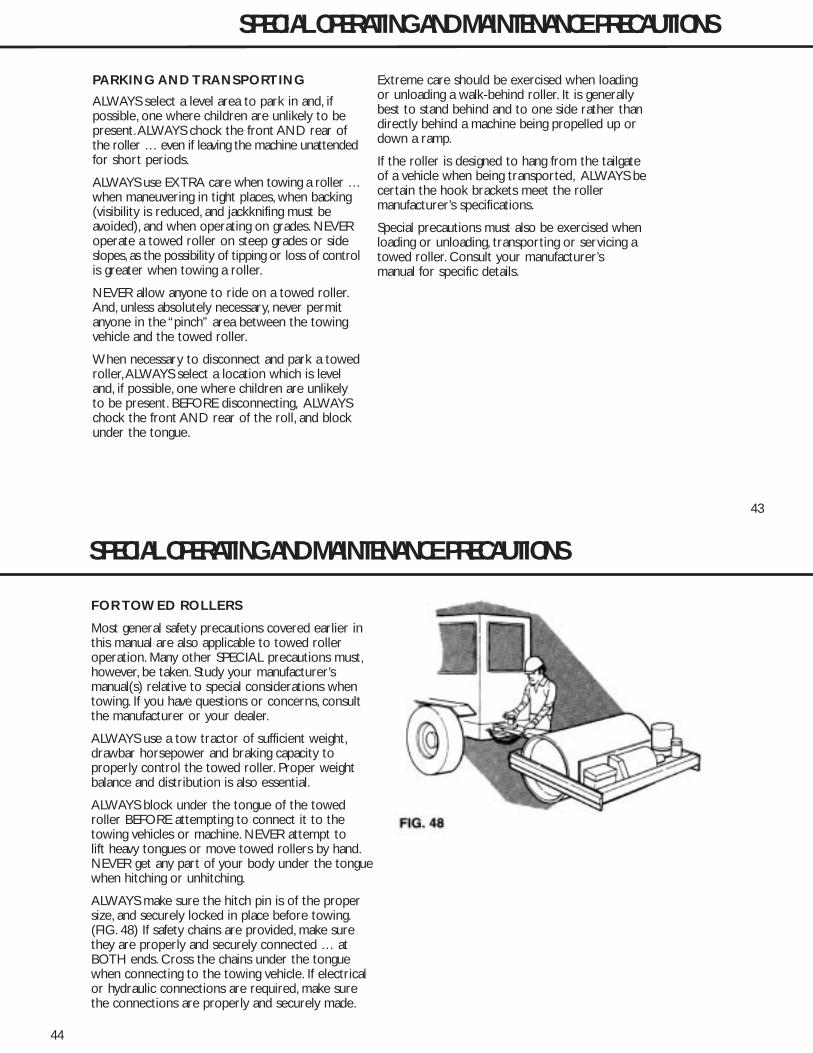
43
PARKING AND TRANSPORTING
ALWAYS select a level area to park in and, ifpossible, one where children are unlikely to bepresent.ALWAYS chock the front AND rear ofthe roller … even if leaving the machine unattendedfor short periods.
ALWAYS use EXTRA care when towing a roller …when maneuvering in tight places, when backing(visibility is reduced, and jackknifing must beavoided), and when operating on grades. NEVERoperate a towed roller on steep grades or sideslopes, as the possibility of tipping or loss of controlis greater when towing a roller.
NEVER allow anyone to ride on a towed roller.And, unless absolutely necessary, never permitanyone in the “pinch” area between the towingvehicle and the towed roller.
When necessary to disconnect and park a towedroller,ALWAYS select a location which is leveland, if possible, one where children are unlikelyto be present. BEFORE disconnecting, ALWAYSchock the front AND rear of the roll, and blockunder the tongue.
Extreme care should be exercised when loadingor unloading a walk-behind roller. It is generallybest to stand behind and to one side rather thandirectly behind a machine being propelled up ordown a ramp.
If the roller is designed to hang from the tailgateof a vehicle when being transported, ALWAYS becertain the hook brackets meet the rollermanufacturer’s specifications.
Special precautions must also be exercised whenloading or unloading, transporting or servicing atowed roller. Consult your manufacturer’smanual for specific details.
SPECIAL OPERATING AND MAINTENANCE PRECAUTIONS
KE40246P3 6/9/05 3:19 PM Page 43
44
FOR TOWED ROLLERS
Most general safety precautions covered earlier inthis manual are also applicable to towed rolleroperation. Many other SPECIAL precautions must,however, be taken. Study your manufacturer’smanual(s) relative to special considerations whentowing. If you have questions or concerns, consultthe manufacturer or your dealer.
ALWAYS use a tow tractor of sufficient weight,drawbar horsepower and braking capacity toproperly control the towed roller. Proper weightbalance and distribution is also essential.
ALWAYS block under the tongue of the towedroller BEFORE attempting to connect it to thetowing vehicles or machine. NEVER attempt tolift heavy tongues or move towed rollers by hand.NEVER get any part of your body under the tonguewhen hitching or unhitching.
ALWAYS make sure the hitch pin is of the propersize, and securely locked in place before towing.(FIG. 48) If safety chains are provided, make surethey are properly and securely connected … atBOTH ends. Cross the chains under the tonguewhen connecting to the towing vehicle. If electricalor hydraulic connections are required, make surethe connections are properly and securely made.
SPECIAL OPERATING AND MAINTENANCE PRECAUTIONS
KE40246P3 6/9/05 3:19 PM Page 44
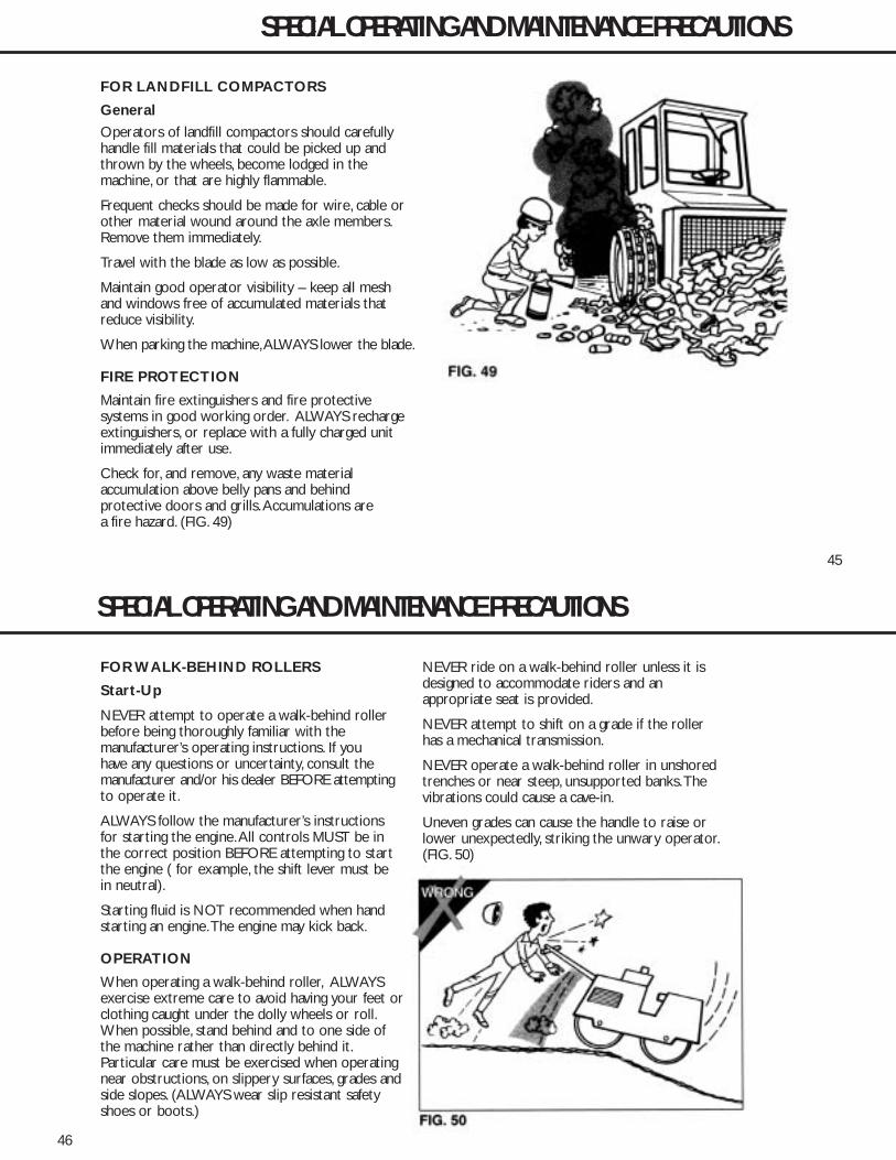
45
FOR LANDFILL COMPACTORS
General
Operators of landfill compactors should carefullyhandle fill materials that could be picked up andthrown by the wheels, become lodged in themachine, or that are highly flammable.
Frequent checks should be made for wire, cable orother material wound around the axle members.Remove them immediately.
Travel with the blade as low as possible.
Maintain good operator visibility – keep all meshand windows free of accumulated materials thatreduce visibility.
When parking the machine,ALWAYS lower the blade.
FIRE PROTECTION
Maintain fire extinguishers and fire protectivesystems in good working order. ALWAYS rechargeextinguishers, or replace with a fully charged unitimmediately after use.
Check for, and remove, any waste material accumulation above belly pans and behindprotective doors and grills.Accumulations are a fire hazard. (FIG. 49)
SPECIAL OPERATING AND MAINTENANCE PRECAUTIONS
KE40246P3 6/9/05 3:19 PM Page 45
46
FOR WALK-BEHIND ROLLERS
Start-Up
NEVER attempt to operate a walk-behind rollerbefore being thoroughly familiar with the manufacturer’s operating instructions. If you have any questions or uncertainty, consult themanufacturer and/or his dealer BEFORE attemptingto operate it.
ALWAYS follow the manufacturer’s instructionsfor starting the engine.All controls MUST be inthe correct position BEFORE attempting to startthe engine ( for example, the shift lever must bein neutral).
Starting fluid is NOT recommended when handstarting an engine.The engine may kick back.
OPERATION
When operating a walk-behind roller, ALWAYSexercise extreme care to avoid having your feet orclothing caught under the dolly wheels or roll.When possible, stand behind and to one side ofthe machine rather than directly behind it.Particular care must be exercised when operatingnear obstructions, on slippery surfaces, grades andside slopes. (ALWAYS wear slip resistant safetyshoes or boots.)
NEVER ride on a walk-behind roller unless it isdesigned to accommodate riders and anappropriate seat is provided.
NEVER attempt to shift on a grade if the rollerhas a mechanical transmission.
NEVER operate a walk-behind roller in unshoredtrenches or near steep, unsupported banks.Thevibrations could cause a cave-in.
Uneven grades can cause the handle to raise orlower unexpectedly, striking the unwary operator.(FIG. 50)
SPECIAL OPERATING AND MAINTENANCE PRECAUTIONS
KE40246P3 6/9/05 3:19 PM Page 46
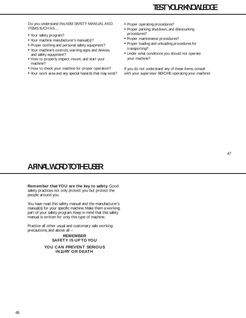
47
Do you understand this AEM SAFETY MANUAL ANDITEMS SUCH AS …
• Your safety program?• Your machine manufacturer’s manual(s)?• Proper clothing and personal safety equipment?• Your machine’s controls, warning signs and devices,
and safety equipment?• How to properly inspect, mount, and start your
machine?• How to check your machine for proper operation?• Your work area and any special hazards that may exist?
• Proper operating procedures?• Proper parking, shutdown, and dismounting
procedures?• Proper maintenance procedures?• Proper loading and unloading procedures for
transporting?• Under what conditions you should not operate
your machine?
If you do not understand any of these items, consultwith your supervisor BEFORE operating your machine!
TEST YOUR KNOWLEDGE
KE40246P3 6/9/05 3:19 PM Page 47
48
Remember that YOU are the key to safety. Goodsafety practices not only protect you but protect thepeople around you.
You have read this safety manual and the manufacturer’smanual(s) for your specific machine. Make them a workingpart of your safety program. Keep in mind that this safetymanual is written for only this type of machine.
Practice all other usual and customary safe workingprecautions, and above all –
REMEMBERSAFETY IS UP TO YOU
YOU CAN PREVENT SERIOUSINJURY OR DEATH
A FINAL WORD TO THE USER
KE40246P3 6/9/05 3:19 PM Page 48

NOTICE OF COPYRIGHT PROTECTIONAEM Safety Manuals are protected as a copyrighted work withownership duly registered with the Copyright Office,Washington,D.C.Any reproduction, translation, decompiling or other use of anAEM Safety Manual, or portion thereof, or the creation of deriv-
ative works based on an AEM Safety Manual,without the prior writ-ten approval of AEM, is expressly prohibited. Copyright infringe-ment can result in civil and criminal sanctions, damages and otherpenalties being imposed.
Copyright © 1978 AEM (Association of Equipment Manufacturers)Former Copyright © CIMA (Construction Industry Manufacturer Association)
Revised 6/02, 9/04
SAFETY ALERT SYMBOLThis Safety Alert Symbol meansATTENTION is involved!
The Safety Alert Symbol identifies important safetymessages on machines, safety signs, in manuals, orelsewhere.When you see this symbol, be alert tothe possibility of personal injury or death. Followthe instructions in the safety message.
Why is SAFETY important to YOU?
3 BIG REASONS:• Accidents KILL or DISABLE• Accidents COST• Accidents CAN BE AVOIDED
KE40246P1 6/9/05 3:14 PM Page 2
KE40246P1 6/9/05 3:14 PM Page 1

2005-CE-RD11AEC-Q.fm
William Lahner Greg OrzalVice President of Engineering Manager, Product Engineering
WACKER CORPORATIONDate / Datum / Fecha / Date
EC DECLARATION OF CONFORMITYCE-KONFORMITÄTSERKLÄRUNG
DECLARACIÓN DE CONFORMIDAD DE LA CE DÉCLARATION DE CONFORMITÉ C.E.
WACKER CORPORATION, N92 W15000 ANTHONY AVENUE, MENOMONEE FALLS, WISCONSIN USA
hereby certifies that the construction equipment specified hereunder / bescheinigt, daß das Baugerät / certifica que la máquina de construcción / atteste que le matériel :
1. Category / Art / Categoría / CatégorieVibrating Ride-On Rollers
Fahrergesteuerte Vibrationswalzen Rodillos Vibrantes con Conductor Montado
Rouleaux Compacteurs Vibrants à Conducteur Porté
2. Type / Typ / Tipo / Type RD 11AEC
3. Item number of equipment / Artikelnummer / Número de referencia de la máquina / Numéro de référence du matériel :
0007695
4. Net installed power / Absolute installierte Leistung / Potencia instalada neta / Puissance installée nette :
13,4 kW
Has been sound tested per Directive 2000/14/EC / In Übereinstimmung mit Richtlinie 2000/14/EG bewertet worden ist / Ha sido ensayado en conformidad con la norma 2000/14/CE / A été mis à l’épreuve conforme aux dispositions de la directive 2000/14/CEE :
and has been produced in accordance with the following standards:und in Übereinstimmung mit folgenden Richtlinien hergestellt worden ist:y ha sido fabricado en conformidad con las siguientes normas:et a été produit conforme aux dispositions des directives européennes ci-après :
2000/14/EC2002/88/EC89/336/EEC98/37/EECEN 500-1EN 500-4
AUTHORIZED REPRESENTATIVE IN THE EUROPEAN UNIONBEVOLLMÄCHTIGTER VERTRETER FÜR DIE EUROPÄISCHE GEMEINSCHAFTREPRESENTANTE AUTORIZADO EN LA UNIÓN EUROPEAREPRÉSENTANT AGRÉÉ AUPRÈS DE L’UNION EUROPÉENNE
WACKER CONSTRUCTION EQUIPMENT AGPreußenstraße 4180809 München
Conformity Assessment Procedure / Konformitätsbewertungsverfahren / Procedimiento para ensayar conformidad / Procédé pour l’épreuve de conformité
Name and address of notified body / Bei folgender einbezogener Prüfstelle / Oficina matriculadora / Organisme agrée
Measured sound power level / Gemessener Schall-leistungspegel / Nivel de potencia acústica determinado / Niveau de puissance acoustique fixé
Guaranteed sound power level / Garantierter Schallleistungspegel / Nivel de potencia acústica garantizado / Niveau de puissance acoustique garanti
Annex VIII BSI, 389 Chiswick High Road, London W4 4AL
United Kingdom
103 dB(A) 109 dB(A)
03.01.05

Wacker Construction Equipment AG · Preußenstraße 41 · D-80809 München · Tel.: +49-(0)89-3 54 02 - 0 · Fax: +49 - (0)89-3 54 02-3 90Wacker Corporation · P.O. Box 9007 · Menomonee Falls, WI 53052-9007 · Tel. : (262) 255-0500 · Fax: (262) 255-0550 · Tel. : (800) 770-0957Wacker Asia Pacific Operations · Skyline Tower, Suite 2303, 23/F · 39 Wang Kwong Road, Kowloon Bay, Hong Kong · Tel. +852 2406 60 32 · Fax: +852 2406 60 21