rolling thunder technical reference manual manual_0.3.pdf · rolling thunder consists of one...
TRANSCRIPT

Release 0.3
Rolling Thunder Technical Reference Manual

2
INTRODUCTION
Introduction
Rolling Thunder consists of one transmitter in a Paragon 3 Rolling
Thunder equipped locomotive and one Rolling Thunder receiver
connected to a bass sub-woofer. The transmitted sounds range from 1hz to
1khz allowing great bass response never achievable in Ho model
railroading.
DCC Characteristics
14 bit addressing
7 bit addressing (1-127)
Operations mode support for all CV settings
Configuration Variable Access Acknowledgement in Service mode
Direct, Address Only, Physical Addressing and Paged CV Addressing
Modes support in Service Mode including Write and Verify
DC characteristics
DCMaster uses Direct Mode for CV Programming
All CV’s Programmable and Readable
General Characteristics
Locomotive Mute Silences the Bass Sub-Woofer
Locomotive Volume Controls the Bass Sub-Woofer Volume
ThunderTune
Tune you Thunder Sounds; Set the parameters best for your layout
Full Graphical Display; Use Computer with Windows and USB Port
Read Locomotive Track Voltage as the Locomotive Moves
3
Operation
Connect your Rolling Thunder receiver to your train track power
using the supplied power cable. Connect your bass sub-woofer to the
rca jack on the receiver and power on the sub-woofer. Once power is
supplied to the receiver, the front led will blink rapidly about 5 seconds.
During this time, if service mode is detected, the receiver will accept
any service mode commands. If service mode is not detected, the led
lights solidly, indicating proper functioning. When a Rolling Thunder
equipped locomotive reaches the vicinity of the receiver, the receiver
starts to play the low frequency sounds received from the locomotive.
As the locomotive moves away from the receiver, the sounds will
diminish and go off until another Rolling Thunder equipped
locomotive approaches the receiver. The distance of reception may be
changed by varying the transmitter power CV213 in the locomotive.
Each Rolling Thunder locomotive should be set to a unique transmit
frequency. CV212 and CV213 allows for 58 unique locomotive transmit
frequencies.
Pressing the switch next to the led enters DCC programming in
operations mode for the receiver. Pressing the switch causes the led to
flash rapidly, indicating the receiver is ready to receive DCC commands.
The bass sub-woofer is disabled during DCC programming. Several
commands cause the receiver to reset (CV213, CV8=8) while all other
CV writes will not cause a reset. Pressing the switch while the led is
rapidly flashing in DCC programming mode exits DCC programming
mode and the bass sub-woofer is enabled.

4
Operation
Factory Reset
Hold the switch for 3 seconds while apply power forces a receiver
factory reset.
Operations Mode CV Programming
After the receiver is powered up using track power and stops flashing,
press the button to enter DCC programming. The bass sub-woofer is
disabled during DCC programming. Several commands cause the
receiver to reset (CV213, CV8=8) while all other CV writes will not
cause a reset. Pressing the switch while the led is rapidly flashing exits
the programming mode.
Multiple Transmitters
Program the Rolling Thunder locomotive to a unique channel
(CV212). The factory default is channel 1. Each transmitter must have
a unique address. The receiver has a digital filter for the receive signal
strength. As the locomotive gets closer and further away from the
receiver, the signal strength increases or decreases. Once the receiver
strength attains this level, the receiver locks to the locomotive. Once the
signal strength reaches the signal level of CV135, the volume starts
increasing at the rate specified by CV130, until the volume reaches
maximum volume specified by CV131. The receiver scans the selected
channels if insufficient signal strength is found. The signal strength
necessary is set by CV141. The channels scanned are set by CV142 and
CV143. For a single transmitter system, CV142 and CV143 are set to
channel 1, the default transmitter channel.

5
Operation
The receiver only scans channels in the selected frequency sub-band,
which is controlled by CV213. The transmitter and receiver must both
be set to the same sub-band.
Default Receiver Mode: Single transmitter operating on channel
one.
Please Note: The CV Defaults may vary from Locomotive to
Locomotive.
6
SYSTEM CVs
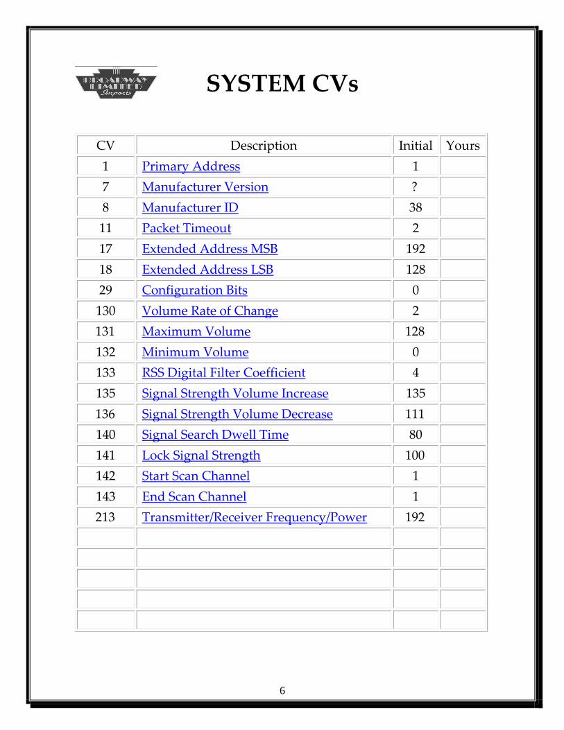
CV Description Initial Yours
1 Primary Address 1
7 Manufacturer Version ?
8 Manufacturer ID 38
11 Packet Timeout 2
17 Extended Address MSB 192
18 Extended Address LSB 128
29 Configuration Bits 0
130 Volume Rate of Change 2
131 Maximum Volume 128
132 Minimum Volume 0
133 RSS Digital Filter Coefficient 4
135 Signal Strength Volume Increase 135
136 Signal Strength Volume Decrease 111
140 Signal Search Dwell Time 80
141 Lock Signal Strength 100
142 Start Scan Channel 1
143 End Scan Channel 1
213 Transmitter/Receiver Frequency/Power 192

7
SYSTEM CVs
CV1
Receiver Primary Address
Description
The Receivers Primary Address is Stored Here
Values
Bits 0-6 contain an address with a value between 1 and 127
Initial Value
1
Related CVs
None
Bit 7 Bit 0
0 A6 A5 A4 A3 A2 A1 A0
The decoder responds to all valid commands if the address matches
the value in CV1 and CV29 Bit 5 is set to 0.
Programming CV1 will program CV19 (Consists Address) to zero
and programs CV29 Bit 5 to 0 (Extended Addressing Off).
8
SYSTEM CVs
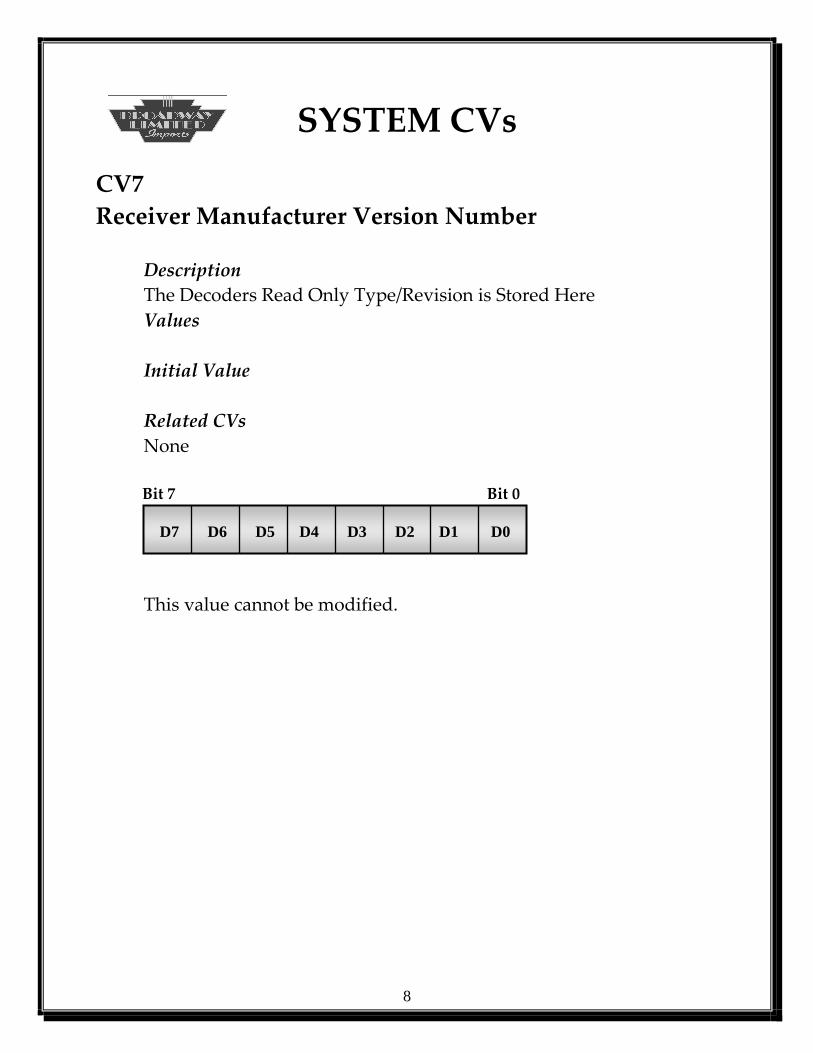
CV7
Receiver Manufacturer Version Number
Description
The Decoders Read Only Type/Revision is Stored Here
Values
Initial Value
Related CVs
None
Bit 7 Bit 0
D7 D6 D5 D4 D3 D2 D1 D0
This value cannot be modified.

9
SYSTEM CVs
CV8
Receiver Manufacturer ID
Description
The Decoders NMRA Assigned Number is Stored Here. Broadway
Limited is assigned ID 38.
Values
Initial Value
38
Related CVs
Bit 7 Bit 0
0 0 1 0 0 1 1 0
Setting CV8 to 8 resets all CVs back to their original manufactured
values
Receiver Note: The receiver will automatically reset when this CV
is changed.
10
SYSTEM CVs
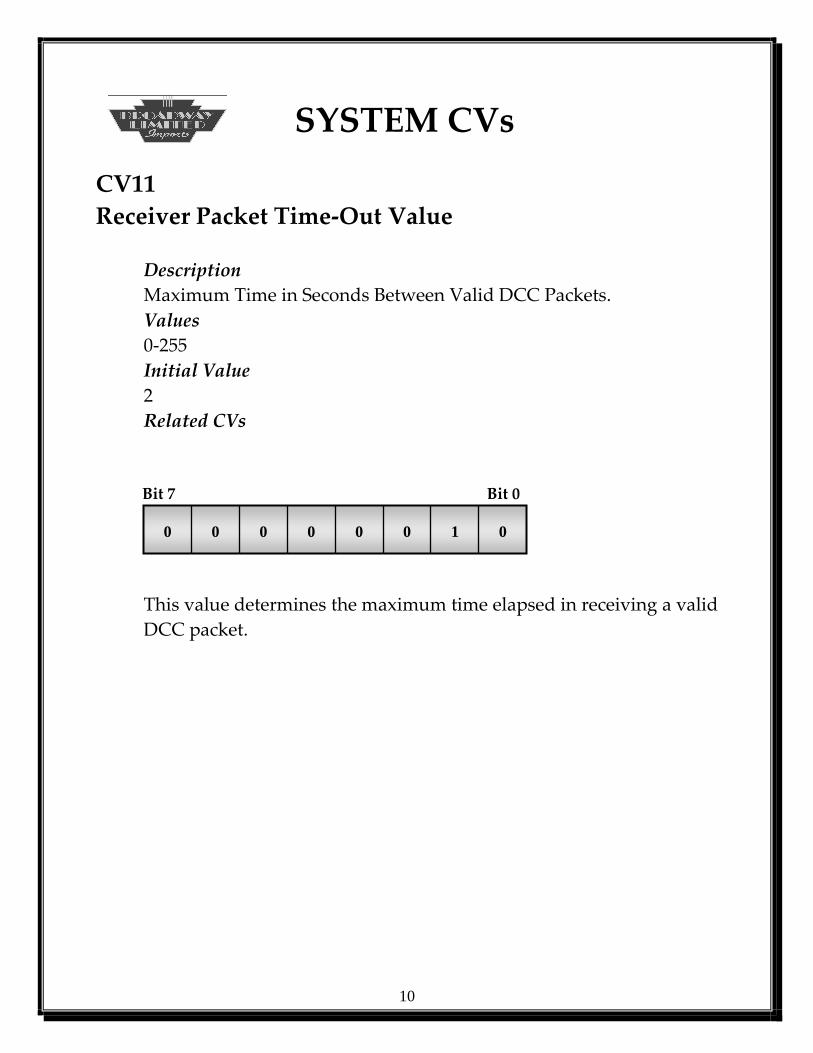
CV11
Receiver Packet Time-Out Value
Description
Maximum Time in Seconds Between Valid DCC Packets.
Values
0-255
Initial Value
2
Related CVs
Bit 7 Bit 0
0 0 0 0 0 0 1 0
This value determines the maximum time elapsed in receiving a valid
DCC packet.

11
SYSTEM CVs
CV17 and CV18
Receiver Extended Address
Description
This Value Contains the Decoders Extended Address and is Valid
Only if CV29 Bit 5 is 1
Values
Values From 0 to 10239 are Valid
Initial Value
1100 0000 1000 0000 (Engine 128)
Related CVs
CV29 Bit 5 Bit 15 Bit 8
1 1 A13 A12 A11 A10 A9 A8
CV17 Extended Address MSB
Bit 7 Bit 0
A7 A6 A5 A4 A3 A2 A1 A0
CV18 Extended Address LSB
CV17 Valid Values are 1100 0000 thru 1110 0111
CV18 Valid Values are 0000 0000 thru 0000 0000
12
SYSTEM CVs
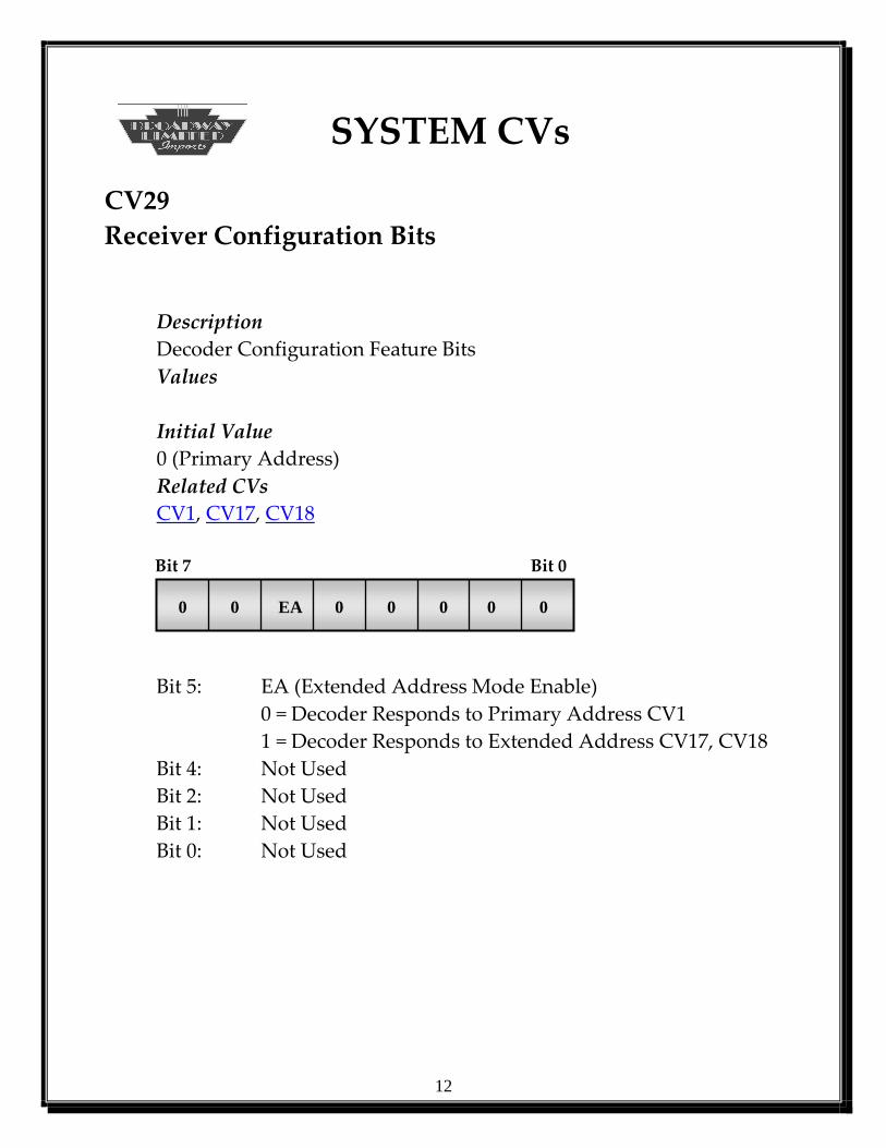
CV29
Receiver Configuration Bits
Description
Decoder Configuration Feature Bits
Values
Initial Value
0 (Primary Address)
Related CVs
CV1, CV17, CV18
Bit 7 Bit 0
0 0 EA 0 0 0 0 0
Bit 5: EA (Extended Address Mode Enable)
0 = Decoder Responds to Primary Address CV1
1 = Decoder Responds to Extended Address CV17, CV18
Bit 4: Not Used
Bit 2: Not Used
Bit 1: Not Used
Bit 0: Not Used

13
SYSTEM CVs
CV130
Receivers Volume Rate of Change
Description
Rate Volume Increases or Decreases with Signal Strength
Values
Initial Value
2
Related CVs
CV131, CV132, CV133
Bit 7 Bit 0
0 0 0 0 0 0 1 0
This value sets the rate of change of volume once the receiver detects
the Rolling Thunder Equipped Locomotive. The volume is
increased by this value. A larger number means the volume
increases much quicker.
14
SYSTEM CVs
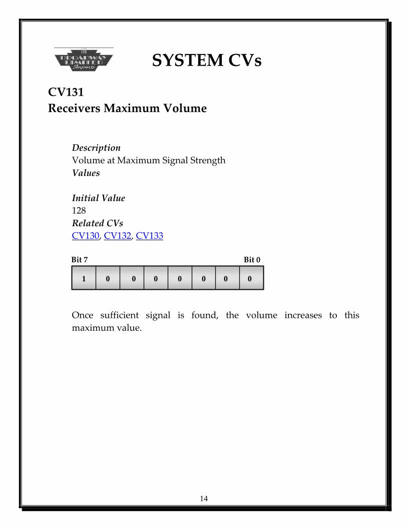
CV131
Receivers Maximum Volume
Description
Volume at Maximum Signal Strength
Values
Initial Value
128
Related CVs
CV130, CV132, CV133
Bit 7 Bit 0
1 0 0 0 0 0 0 0
Once sufficient signal is found, the volume increases to this
maximum value.

15
SYSTEM CVs
CV132
Receivers Minimum Volume
Description
Volume at Minimum Signal Strength
Values
Initial Value
0
Related CVs
CV130, CV131, CV133
Bit 7 Bit 0
0 0 0 0 0 0 0 0
Once the signal falls to an insufficient value, the volume decreases by
CV130 until this value (CV132) is reached.
16
SYSTEM CVs
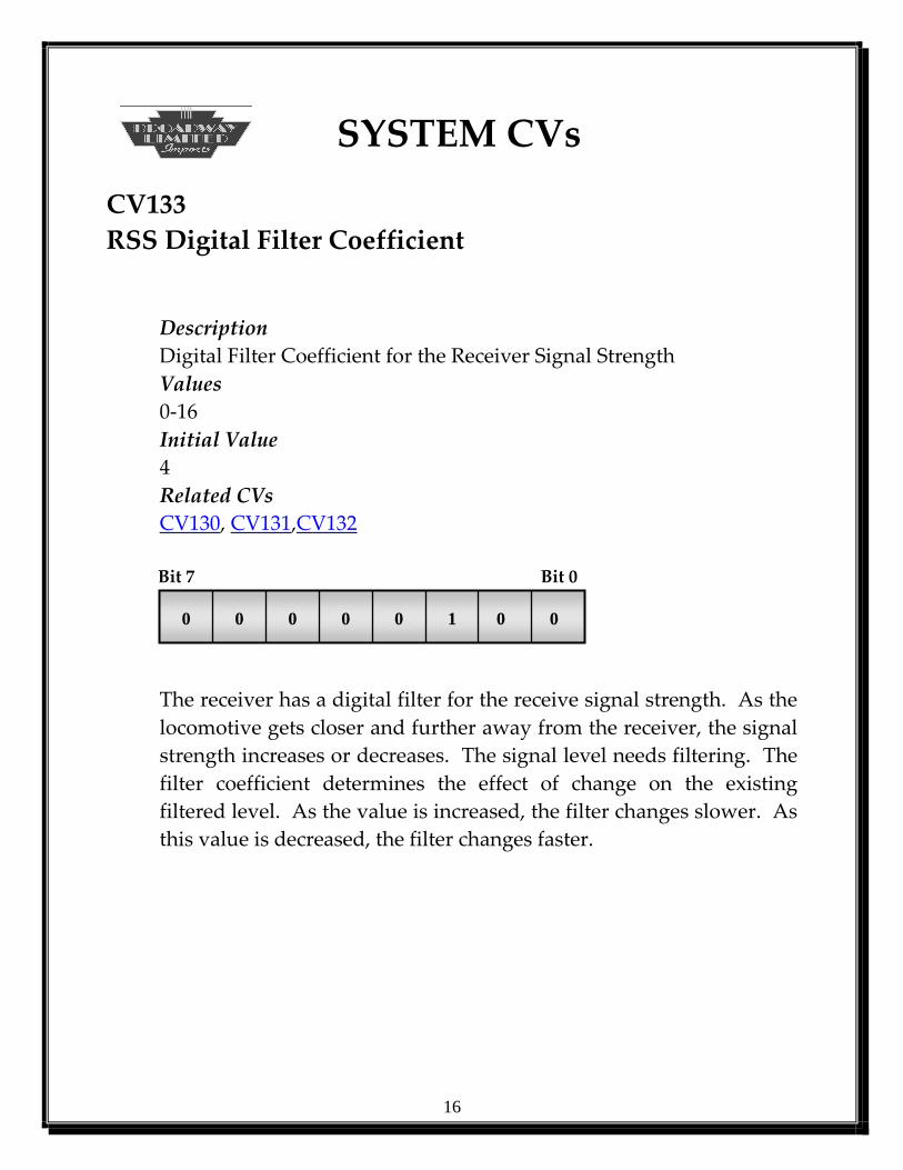
CV133
RSS Digital Filter Coefficient
Description
Digital Filter Coefficient for the Receiver Signal Strength
Values
0-16
Initial Value
4
Related CVs
CV130, CV131,CV132
Bit 7 Bit 0
0 0 0 0 0 1 0 0
The receiver has a digital filter for the receive signal strength. As the
locomotive gets closer and further away from the receiver, the signal
strength increases or decreases. The signal level needs filtering. The
filter coefficient determines the effect of change on the existing
filtered level. As the value is increased, the filter changes slower. As
this value is decreased, the filter changes faster.

17
SYSTEM CVs
CV135
Signal Strength Volume Increase
Description
Required Receiver Signal Strength to Increase Sub-Woofer Volume
Values
0-255
Initial Value
135
Related CVs
CV130, CV131,CV132, CV136
Bit 7 Bit 0
1 0 0 1 0 1 1 1
The receiver has a digital filter for the receive signal strength. As the
locomotive gets closer and further away from the receiver, the signal
strength increases or decreases. Once the receiver strength reaches
this level, the volume starts increasing at the increment in CV130.
Note: This value must be greater than CV136.

18
SYSTEM CVs
CV136
Signal Strength Volume Decrease
Description
Required Receiver Signal Strength to Decrease Sub-Woofer Volume
Values
0-255
Initial Value
111
Related CVs
CV130, CV131,CV132, CV135
Bit 7 Bit 0
0 1 1 0 1 1 1 1
The receiver has a digital filter for the receive signal strength. As the
locomotive gets closer and further away from the receiver, the signal
strength increases or decreases. Once the receiver strength falls
below this level, the volume starts decreasing at the increment in
CV130.
Note: This value must be less than CV135.
19
SYSTEM CVs
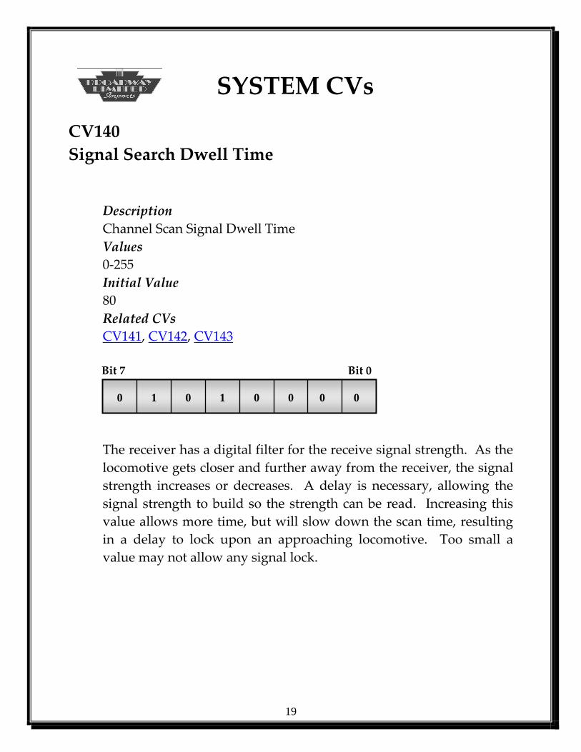
CV140
Signal Search Dwell Time
Description
Channel Scan Signal Dwell Time
Values
0-255
Initial Value
80
Related CVs
CV141, CV142, CV143
Bit 7 Bit 0
0 1 0 1 0 0 0 0
The receiver has a digital filter for the receive signal strength. As the
locomotive gets closer and further away from the receiver, the signal
strength increases or decreases. A delay is necessary, allowing the
signal strength to build so the strength can be read. Increasing this
value allows more time, but will slow down the scan time, resulting
in a delay to lock upon an approaching locomotive. Too small a
value may not allow any signal lock.
20
SYSTEM CVs
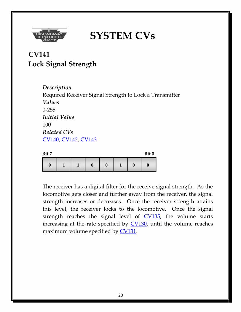
CV141
Lock Signal Strength
Description
Required Receiver Signal Strength to Lock a Transmitter
Values
0-255
Initial Value
100
Related CVs
CV140, CV142, CV143
Bit 7 Bit 0
0 1 1 0 0 1 0 0
The receiver has a digital filter for the receive signal strength. As the
locomotive gets closer and further away from the receiver, the signal
strength increases or decreases. Once the receiver strength attains
this level, the receiver locks to the locomotive. Once the signal
strength reaches the signal level of CV135, the volume starts
increasing at the rate specified by CV130, until the volume reaches
maximum volume specified by CV131.
21
SYSTEM CVs
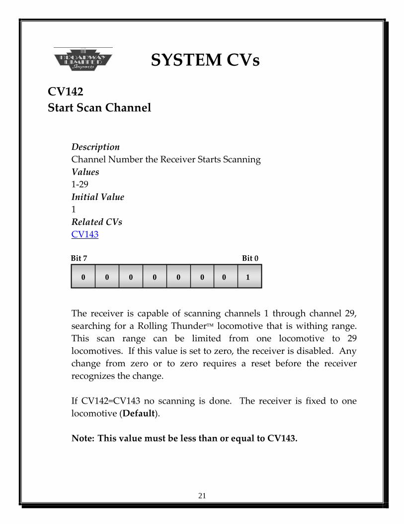
CV142
Start Scan Channel
Description
Channel Number the Receiver Starts Scanning
Values
1-29
Initial Value
1
Related CVs
CV143
Bit 7 Bit 0
0 0 0 0 0 0 0 1
The receiver is capable of scanning channels 1 through channel 29,
searching for a Rolling Thunder locomotive that is withing range.
This scan range can be limited from one locomotive to 29
locomotives. If this value is set to zero, the receiver is disabled. Any
change from zero or to zero requires a reset before the receiver
recognizes the change.
If CV142=CV143 no scanning is done. The receiver is fixed to one
locomotive (Default).
Note: This value must be less than or equal to CV143.

22
SYSTEM CVs
CV143
End Scan Channel
Description
Channel Number the Receiver Starts Scanning
Values
1-29
Initial Value
1
Related CVs
CV142
Bit 7 Bit 0
0 0 0 0 0 0 0 1
The receiver is capable of scanning channels 1 through channel 29,
searching for a Rolling Thunder locomotive that is within range.
This scan range can be limited from one locomotive to 29
locomotives.
If CV142=CV143 no scanning is done. The receiver is fixed to one
locomotive (Default).
Note: This value must be greater than or equal to CV142.
23
SYSTEM CVs
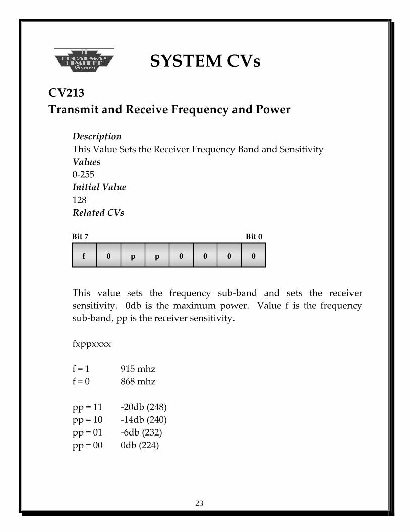
CV213
Transmit and Receive Frequency and Power
Description
This Value Sets the Receiver Frequency Band and Sensitivity
Values
0-255
Initial Value
128
Related CVs
Bit 7 Bit 0
f 0 p p 0 0 0 0
This value sets the frequency sub-band and sets the receiver
sensitivity. 0db is the maximum power. Value f is the frequency
sub-band, pp is the receiver sensitivity.
fxppxxxx
f = 1 915 mhz
f = 0 868 mhz
pp = 11 -20db (248)
pp = 10 -14db (240)
pp = 01 -6db (232)
pp = 00 0db (224)
24
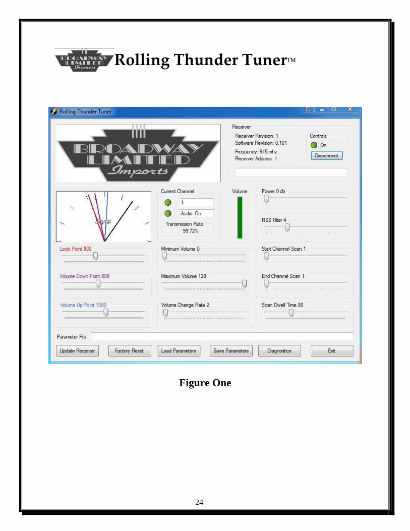
Rolling Thunder Tuner
Figure One

25
Rolling Thunder Tuner
Installation
Install ThunderTune on your PC. Plug in the USB cable and install the drivers following the
operating systems install procedures. Use the supplied drivers when asked. Now connect the
cable’s other end to the receiver. Power on the receiver and your Rolling Thunder equipped
Locomotive. Run the software program . Figure One should now be displayed. Placement of
the receiver will greater very the response. Try different locations as you attempt to tune for
your preference.
Version Information
The Rolling Thunder Receiver Version as well as the Software Version is given here after the
USB connection is enabled.
Power LED
The Power LED mirrors the receivers front red LED.
Receiver
Receiver revision, Rolling Thunder Tuner software revision, the current receiver frequency band
and receivers ID or CV1 (Short Address) is displayed here.

26
Rolling Thunder Tuner
Signal Meter
Signal. The Rolling Thunder Receivers Signal Meter displays four needles. The Black needle
is the signal strength needle, indicating the received strength of the transmitting Locomotive.
Before bass sounds are played, the black needle must be to the right of all the other needles.
Lock Point (CV141). The Lock Point needle (Red needle) indicates the necessary signal
strength needed by the receiver to lock on to the Current Channel Scanned. Changing the Lock
Point Slider changes the receiver’s value temporarily. To save the change to the receiver, press
the Update Receiver Button. This button causes the receiver to save all the temporary values.
This value should always be higher than the background noise. Determine the maximum noise
by running Diagnostics with no train transmitters. Determine the largest signal and click the
mouse on that channel. The maximum signal strength is displayed. Make sure the Lock Point is
greater than this value. If the lock point were lower, a scan would force a false lock onto a non-
existent transmitter.
Volume Up Point (CV135). Once the signal strength needle reaches and passes the Volume Up
needle (Violet Needle), the bass volume starts increasing. The Volume indicator’s blue bar will
rise. The Volume Up needle must be positioned to the right of the Volume Down needle. The
bass volume will remain at its current level when the signal needle is in the space between the
Volume Up needle and the Volume Down needle. The Volume Maximum may be set with the
Maximum Volume slider. The Volume indicator indicates the maximum volume set to by the
Maximum Volume slider. The Volume Change Rate Slider may control the rate of change of the
increasing volume.
Volume Down Point (CV136). Once the signal strength needle falls below the Volume Down
needle (Blue needle), the bass volume starts to decrease and is indicated by the blue Volume
indicator. The Volume Down needle must be positioned to the left of the Volume Up needle.
The bass volume will remain at its current level when the signal needle is in the space between
the Volume Up needle and the Volume Down needle. The Volume Minimum may be set with
the Minimum Volume slider. The Volume indicator indicates the minimum volume set to by the
Minimum Volume slider. The Volume Change Rate Slider may control the rate of change of the
decreasing volume.

27
Rolling Thunder Tuner
Current Channel
Current Channel LED
When the receiver is locked, the Current Channel LED displays green and the Current Channel
that the receiver is locked is displayed. When the receiver is searching for a transmitter
(Locomotive), the Current Channel will change from Start Channel Scan (CV142) to End
Channel Scan (CV143) and stop and turn Green if a channel within range is found.
Mute LED
If the transmitter that the receiver is locked onto is muted, the mute LED will light, indicating a
muted condition.
Volumes
Minimum Volume (CV132). This value sets the lowest volume level heard when the signal
level is below the Volume Down needle.
Maximum Volume (CV131). This value sets the highest volume level heard when the signal
level is greater than the Volume Up needle.
Volume Change Rate (CV130). This value determines the rate at which the volume changes
when the signal is greater than the Volume Up needle or less than the Volume Down needle.
Power and Filters
Receiver Power (CV213). The receiver’s power amplifier may be decreased which will
diminish the range of reception. Decreasing the power level will decrease the area of reception
to a smaller track area.
RSS Filter (CV133). The receiver signal strength’s digital filter may be altered. A higher value
slows the response, which is better for slow moving trains. However, fast moving trains should
use a lower value, so the track area the bass starts playing is not over shot.
28
Rolling Thunder Tuner
Channel Scanning
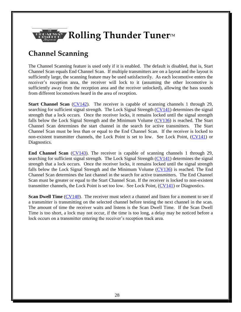
The Channel Scanning feature is used only if it is enabled. The default is disabled, that is, Start
Channel Scan equals End Channel Scan. If multiple transmitters are on a layout and the layout is
sufficiently large, the scanning feature may be used satisfactorily. As each locomotive enters the
receiver’s reception area, the receiver will lock to it (assuming the other locomotive is
sufficiently away from the reception area and the receiver unlocked), allowing the bass sounds
from different locomotives heard in the area of reception.
Start Channel Scan (CV142). The receiver is capable of scanning channels 1 through 29,
searching for sufficient signal strength. The Lock Signal Strength (CV141) determines the signal
strength that a lock occurs. Once the receiver locks, it remains locked until the signal strength
falls below the Lock Signal Strength and the Minimum Volume (CV136) is reached. The Start
Channel Scan determines the start channel in the search for active transmitters. The Start
Channel Scan must be less than or equal to the End Channel Scan. If the receiver is locked to
non-existent transmitter channels, the Lock Point is set to low. See Lock Point, (CV141) or
Diagnostics.
End Channel Scan (CV143). The receiver is capable of scanning channels 1 through 29,
searching for sufficient signal strength. The Lock Signal Strength (CV141) determines the signal
strength that a lock occurs. Once the receiver locks, it remains locked until the signal strength
falls below the Lock Signal Strength and the Minimum Volume (CV136) is reached. The End
Channel Scan determines the last channel in the search for active transmitters. The End Channel
Scan must be greater or equal to the Start Channel Scan. If the receiver is locked to non-existent
transmitter channels, the Lock Point is set too low. See Lock Point, (CV141) or Diagnostics.
Scan Dwell Time (CV140). The receiver must select a channel and listen for a moment to see if
a transmitter is transmitting on the selected channel before testing the next channel in the scan.
The amount of time the receiver waits and listens is the Scan Dwell Time. If the Scan Dwell
Time is too short, a lock may not occur, if the time is too long, a delay may be noticed before a
lock occurs on a transmitter entering the receiver’s reception track area.
29
Rolling Thunder Tuner
Configuration Management
Update Receiver. All parameter changes are updated within the receiver immediately. But the
changes are only temporary unless the Update Receiver button is selected. Once selected, the
parameters are saved and will become the new settings even after power down.
Factory Reset. Pressing this button will change all parameters to the factory default conditions.
All changed parameters will be lost.
Load/Save Parameters. The changed parameters may be saved for later use. The parameters
may be saved to a file name of your choice. In addition, the parameters may be restored from a
file that was previously saved. This feature allows restoration of different configurations. The
parameter file could be loaded and then saved as the new power on defaults.
Transmission Rate. Once the receiver locks to a transmitter, all valid receptions are tracked.
Transmissionr rates should be over 90% for acceptable operations. Clicking your mouse in the
Transmission Rate Box resets the rate to 100%.
Exit. Pressing this button terminates the software interface.

30
Rolling Thunder Tuner
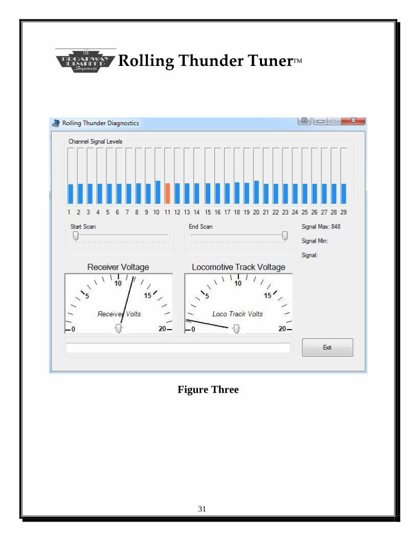
Diagnostics
During Diagnostics, the bass sounds are disabled. The diagnostics indicates the receiver voltage
and shows the signal strengths of all channels. Make sure all transmitters are off or ignore the
Channel Signal Levels for the transmitters that are on. Set the Start Scan for 1 and the End Scan
for 29. Note the highest signal level (Figure Two). Position the mouse cursor on the highest
signal level(Channel 10 for Figure Three). Note the Signal Max: 848 (Figure Three). The Lock
Signal Strength (CV141) must be larger than this value. This signal strength is the noise floor.
Set CV141 or the Lock Point Slider to a larger value than the noise floor. Again, this value is
applicable if scanning is enabled.
Figure Two
31
Rolling Thunder Tuner
Figure Three

32
Rolling Thunder Tuner
Locomotive Track Voltage. Each locomotive’s transmitter may be configured to send the track
voltage read by the locomotive. This ability allows diagnosis of any track areas that may have a
voltage problem or allow a block voltage read. This feature must be enabled on the transmitter.
Set CV213 bit d=1 or the default value would increment by one. Select the transmitter channel
(See Figure Four). The bass sounds are disabled for this feature.
Figure Four