rollover of a truck-tractor and cargo tank semitrailer carrying
TRANSCRIPT

Rollover of a Truck-Tractor and Cargo Tank Semitrailer
Carrying Liquefied Petroleum Gas and Subsequent Fire
Indianapolis, Indiana
October 22, 2009
Accident Report
NTSB/HAR-11/01 PB2011-916201
National
Transportation
Safety Board

NTSB/HAR-11/01 PB2011-916201 Notation 8202A
Adopted July 26, 2011
Highway Accident Report
Rollover of a Truck-Tractor and Cargo Tank Semitrailer
Carrying Liquified Petroleum Gas and Subsequent Fire
Indianapolis, Indiana
October 22, 2009
National
Transportation
Safety Board
490 L’Enfant Plaza, S.W.
Washington, DC 20594

National Transportation Safety Board. 2011. Rollover of a Truck-Tractor and Cargo Tank Semitrailer Carrying
Liquefied Petroleum Gas and Subsequent Fire, Indianapolis, Indiana, October 22, 2009. NTSB/HAR-11/01.
Washington, DC.
Abstract: On October 22, 2009, about 10:38 a.m. eastern daylight time, a 2006 Navistar International truck-tractor
in combination with a 1994 Mississippi Tank Company MC331 specification cargo tank semitrailer (the
combination unit), operated by AmeriGas Propane, L.P., and laden with 9,001 gallons of liquefied petroleum gas,
rolled over on a connection ramp after exiting Interstate 69 (I-69) southbound to proceed south on Interstate 465
(I-465), about 10 miles northeast of downtown Indianapolis, Indiana. The truck driver was negotiating a left curve in
the right lane on the connection ramp when the combination unit began to encroach upon the left lane, occupied by a
2007 Volvo S40 passenger car. The truck driver responded to the Volvo’s presence in the left lane by oversteering
clockwise, causing the combination unit to veer to the right and travel onto the paved right shoulder. The truck
driver’s excessive, rapid, evasive steering maneuver to return the combination unit to the roadway triggered a
sequence of events that caused the cargo tank semitrailer to roll over, decouple from the truck-tractor, penetrate a
steel W-beam guardrail, and collide with a bridge footing and concrete pier column supporting the southbound I-465
overpass. The collision entirely displaced the outside bridge pier column from its footing and resulted in a breach at
the front of the cargo tank that allowed the liquefied petroleum gas to escape, form a vapor cloud, and ignite. The
truck driver and the Volvo driver sustained serious injuries in the accident and postaccident fire, and three occupants
of passenger vehicles traveling on I-465 received minor injuries from the postaccident fire.
Major safety issues were identified in this investigation were cargo tank rollover prevention as they relate
to highway and vehicle design. As a result of its investigation, the National Transportation Safety Board has issued
safety recommendations to the U.S. Department of Transportation, Federal Motor Carrier Safety Administration,
Pipeline and Hazardous Materials Safety Administration, National Highway Traffic Safety Administration, Federal
Highway Administration, and American Association of State Highway and Transportation Officials.
The National Transportation Safety Board is an independent Federal agency dedicated to promoting
aviation, railroad, highway, marine, pipeline, and hazardous materials safety. Established in 1967, the agency is
mandated by Congress through the Independent Safety Board Act of 1974 to investigate transportation accidents,
determine the probable causes of the accidents, issue safety recommendations, study transportation safety issues, and
evaluate the safety effectiveness of government agencies involved in transportation. The NTSB makes public its
actions and decisions through accident reports, safety studies, special investigation reports, safety recommendations,
and statistical reviews.
Recent publications are available in their entirety on the Internet at <http://www.ntsb.gov>. Other information about
available publications also may be obtained from the website or by contacting:
National Transportation Safety Board
Records Management Division, CIO-40
490 L’Enfant Plaza, SW
Washington, DC 20594
(800) 877-6799 or (202) 314-6551
NTSB publications may be purchased, by individual copy or by subscription, from the National Technical
Information Service. To purchase this publication, order report number PB2011-916201 from:
National Technical Information Service
5301 Shawnee Road
Alexandria, Virginia 22312
(800) 553-6847 or (703) 605-6000
The Independent Safety Board Act, as codified at 49 U.S.C. Section 1154(b), precludes the admission into evidence
or use of Board reports related to an incident or accident in a civil action for damages resulting from a matter
mentioned in the report.

NTSB Highway Accident Report
i
Contents
Figures ........................................................................................................................................... iii
Acronyms and Abbreviations .......................................................................................................v
Executive Summary ................................................................................................................... viii
1. Factual Information ...................................................................................................................1 1.1 Accident Narrative .....................................................................................................................1 1.2 Emergency Response .................................................................................................................5 1.3 Injuries .......................................................................................................................................7
1.4 Survival Factors .........................................................................................................................8
1.5 Scene Evidence ..........................................................................................................................8
1.6 Weather ......................................................................................................................................8 1.7 Damage ......................................................................................................................................9 1.8 Vehicle Information (Cargo Tank Combination Unit) ............................................................12
1.8.1 Truck-Tractor .................................................................................................................12
1.8.2 Cargo Tank Semitrailer..................................................................................................14 1.8.3 Periodic Testing and Refurbishment .............................................................................16
1.9 Truck Driver Information ........................................................................................................16 1.9.1 Driving Experience ........................................................................................................17 1.9.2 Medical Information ......................................................................................................17
1.9.3 72-Hour History .............................................................................................................18 1.9.4 Toxicology .....................................................................................................................22
1.10 Motor Carrier Operations .......................................................................................................22
1.10.1 Driver Training ............................................................................................................24
1.10.2 Hours-of-Service Records ...........................................................................................24 1.10.3 Vehicle Maintenance ...................................................................................................25
1.11 Highway Information .............................................................................................................26
1.11.1. Cross-Slope Break ......................................................................................................27 1.11.2 Protection of Bridge Pier Columns ..............................................................................30
1.12 Cargo Tank Motor Vehicles...................................................................................................34 1.12.1 DOT Specification Cargo Tanks .................................................................................34 1.12.2 Crashworthiness of DOT Specification Cargo Tanks .................................................35 1.12.3 Hazardous Materials Carrier Registration ...................................................................36 1.12.4 Rollover Awareness .....................................................................................................37
1.13 Vehicle-Based Rollover Prevention .......................................................................................39
1.13.1 Stability Control Systems ............................................................................................39
1.13.2 Vehicle Design .............................................................................................................43 1.13.3 Performance-Based Standards .....................................................................................49 1.13.4 Partial Loads ................................................................................................................51
2. Analysis .....................................................................................................................................53 2.1 Exclusions ................................................................................................................................53 2.2 Accident Discussion.................................................................................................................55

NTSB Highway Accident Report
ii
2.2.1 Rollover Speed ...............................................................................................................58
2.2.2 Driver Fatigue ................................................................................................................59 2.3 Cargo Tank Rollover Prevention .............................................................................................63
2.3.1 Rollover Prevention Programs .......................................................................................64
2.3.2 Stability Control Systems ..............................................................................................66 2.3.3 Vehicle Design ...............................................................................................................67 2.3.4 Partial Loads ..................................................................................................................69 2.3.5 Cross-Slope Break .........................................................................................................71
2.4 Crashworthiness of DOT Specification Cargo Tanks ..............................................................73
2.4.1 Cargo Tank Breach ........................................................................................................73 2.4.2 Population of Cargo Tanks by DOT Specification ........................................................74 2.4.3 Cargo Tank Head Protection (MC331)..........................................................................75 2.4.4 Cargo Tank Crash Performance .....................................................................................76
2.5 Protection of Bridge Pier Columns ..........................................................................................77 2.5.1 Past Accident Investigations ..........................................................................................79
2.5.2 Risk Assessment ............................................................................................................81
3. Conclusions ...............................................................................................................................82 3.1 Findings....................................................................................................................................82 3.2 Probable Cause.........................................................................................................................84
4. Recommendations ....................................................................................................................85 4.1 New Recommendations ...........................................................................................................85 4.2 Previously Issued Recommendations Reclassified in This Report ..........................................88
5. Appendixes................................................................................................................................90
Appendix A: Investigation and Public Hearing .............................................................................90
Appendix B: Improvements to Connection Ramp ........................................................................ 92 Appendix C: Outdoor Advertising Signs ...................................................................................... 94

NTSB Highway Accident Report
iii
Figures
Figure 1. Accident location ............................................................................................................ 2
Figure 2. Plan view of connection ramp and direction of travel and final rest positions
of the truck-tractor and cargo tank semitrailer ................................................................................ 3
Figure 3. Tire marks indicating redirection of combination unit from the right shoulder
to the right lane ............................................................................................................................... 4
Figure 4. Truck-tractor and cargo tank semitrailer at final rest ..................................................... 5
Figure 5. Fire-damaged truck-tractor ............................................................................................. 9
Figure 6. Collision damage and breach at the lower right side of the cargo tank ........................ 10
Figure 7. Displaced bridge pier column struck by cargo tank semitrailer ................................... 11
Figure 8. Aerial view of the connection ramp and Interstate 465 overpasses ............................. 11
Figure 9. Fifth wheel plate ........................................................................................................... 13
Figure 10. Cargo tank semitrailer (MC331)................................................................................. 15
Figure 11. Location of loading terminal in relation to October 19–22 deliveries ....................... 19
Figure 12. Truck driver’s 72-hour history of activities before the accident ................................ 20
Figure 13. Cross-slope break ....................................................................................................... 27
Figure 14. Bridge pier column protection (before accident). ....................................................... 31
Figure 15. Fundamental design considerations for improving the roll stability of cargo tank
motor vehicles ............................................................................................................................... 43
Figure 16. Double tapered cargo tank with dropped center ......................................................... 45
Figure 17. Roll stability improved by increased track width of 102-inch-wide vehicles ............ 46
Figure 18. Lower CG height and increased track width .............................................................. 48
Figure 19. Rollover sequence....................................................................................................... 55
Figure 20. Tire imprints in the right lane and on the shoulder indicating where the
combination unit rolled over onto its right side ............................................................................ 56
Figure 21. Final rest position of cargo tank semitrailer ............................................................... 57

NTSB Highway Accident Report
iv
Figure 22. Mounting pad and rear-facing fold above upper coupler assembly ........................... 74
Figure B-1. Cross-slope break and bridge pier column protection (before improvements) ........ 92
Figure B-2. Cross-slope break and bridge pier column protection (after improvements) ........... 93

NTSB Highway Accident Report
v
Acronyms and Abbreviations
AAR Association of American Railroads
AASHO American Association of State Highway Officials
AASHTO American Association of State Highway and
Transportation Officials
ABS antilock braking system
AmeriGas/PTI AmeriGas Propane, L.P./Propane Transport International
API American Petroleum Institute
ASME American Society of Mechanical Engineers
BMCS Bureau of Motor Carrier Safety
BP blood pressure
CAMI Civil Aerospace Medical Institute
CDL commercial driver’s license
CDLIS Commercial Driver’s License Information System
CFR Code of Federal Regulations
CG center of gravity
DOT U.S. Department of Transportation
DVIR Driver Vehicle Inspection Report
EDT eastern daylight time
EIGA European Industrial Gases Association
ESC electronic stability control [system]
FHWA Federal Highway Administration
FMCSA Federal Motor Carrier Safety Administration
FMCSRs Federal Motor Carrier Safety Regulations
g acceleration of gravity
GES General Estimates System
GVWR gross vehicle weight rating
HMIS Hazardous Materials Information System
hp horsepower
HVOSM Highway-Vehicle-Object-Simulation Model
I-69 Interstate 69

NTSB Highway Accident Report
vi
I-465 Interstate 465
IFD Indianapolis Fire Department
IMPD Indianapolis Metropolitan Police Department
INDOT Indiana Department of Transportation
IN-TIME Indiana Traffic Incident Management Effort
ISP Indiana State Police
LRFD Load and Resistance Factor Design
LTCCS
LTFD
Large Truck Crash Causation Study
Lawrence Township Fire Department
MC motor carrier [number]
MCMIS Motor Carrier Management Information System
MECA Metropolitan Emergency Communications Agency
mg/dL milligrams per deciliter
m/s2 meters per second/per second
MUTCD Manual on Uniform Traffic Control Devices
MY model year
NADS National Advanced Driving Simulator
NASS National Accident Sampling System
NCHRP National Cooperative Highway Research Program
NHS National Highway System
NHTSA National Highway Traffic Safety Administration
NQT nonquenched and tempered
NTSB National Transportation Safety Board
NTTC National Tank Truck Carriers
PCP phencyclidine
PHMSA Pipeline and Hazardous Materials Safety Administration
psig pounds per square inch, gauge
PTI
QT
Propane Transport International
quenched and tempered
RSC rollover stability control [system]
RSPA Research and Special Programs Administration
SAFER Safety and Fitness Electronic Records

NTSB Highway Accident Report
vii
STAA-82 Surface Transportation Assistance Act
TL test level
TRB Transportation Research Board
UCP unified command post
UMLER Universal Machine Language Equipment Register
UMTRI University of Michigan Transportation Research Institute
UN United Nations
UNECE United Nations Economic Commission for Europe
USDOT U.S. Department of Transportation [number]
VDANL Vehicle Dynamics Analysis, Non-Linear

NTSB Highway Accident Report
viii
Executive Summary
On October 22, 2009, about 10:38 a.m. eastern daylight time, a 2006 Navistar
International truck-tractor in combination with a 1994 Mississippi Tank Company MC331
specification cargo tank semitrailer (the combination unit), operated by AmeriGas Propane, L.P.,
and laden with 9,001 gallons of liquefied petroleum gas, rolled over on a connection ramp after
exiting Interstate 69 (I-69) southbound to proceed south on Interstate 465 (I-465), about 10 miles
northeast of downtown Indianapolis, Indiana.
The truck driver was negotiating a left curve in the right lane on the connection ramp,
which consisted of two southbound lanes, when the combination unit began to encroach upon the
left lane, occupied by a 2007 Volvo S40 passenger car. The truck driver responded to the
Volvo’s presence in the left lane by oversteering clockwise, causing the combination unit to veer
to the right and travel onto the paved right shoulder. Moments later, the truck driver steered
counterclockwise to redirect and return the combination unit from the right shoulder to the right
lane.
The truck driver’s excessive, rapid, evasive steering maneuver triggered a sequence of
events that caused the cargo tank semitrailer to roll over, decouple from the truck-tractor,
penetrate a steel W-beam guardrail, and collide with a bridge footing and concrete pier column
supporting the southbound I-465 overpass. The collision entirely displaced the outside bridge
pier column from its footing and resulted in a breach at the front of the cargo tank that allowed
the liquefied petroleum gas to escape, form a vapor cloud, and ignite. The truck-tractor came to
rest on its right side south of the I-465 overpasses, and the decoupled cargo tank semitrailer came
to rest on its left side, near the bridge footing supporting the southbound I-465 overpass.
The truck driver and the Volvo driver sustained serious injuries in the accident and
postaccident fire, and three occupants of passenger vehicles traveling on I-465 received minor
injuries from the postaccident fire. At the time of the accident, the sky was overcast, winds were
calm, pavement was dry, and the temperature was about 58° F.
The National Transportation Safety Board determines that the probable cause of this
accident was the excessive, rapid, evasive steering maneuver that the truck driver executed after
the combination unit began to encroach upon the occupied left lane. Contributing to the rollover
was the driver’s quickly steering the combination unit from the right shoulder to the right lane,
the reduced cross slope of the paved right shoulder, and the susceptibility of the combination unit
to rollover because of its high center of gravity. Mitigating the severity of the accident was the
bridge design, including the elements of continuity and redundancy, which prevented the
structure from collapsing.

NTSB Highway Accident Report
ix
The following safety issues were identified in this investigation:
Essential elements of a comprehensive rollover prevention program.
Rollover propensity of cargo tank motor vehicles, which provides little tolerance
for operator error.
Safety implications of reduced shoulder cross slope on the roll stability of heavy
commercial vehicles with a high center of gravity.
Lack of quality data necessary for conducting meaningful risk analyses to
evaluate the crash performance of U.S. Department of Transportation
specification cargo tanks.
Absence of guidelines for identifying and protecting bridges vulnerable to
collapse if struck by errant heavy commercial vehicles negotiating direct and
semi-direct connection ramps.
As a result of its investigation, the National Transportation Safety Board has issued safety
recommendations to the U.S. Department of Transportation, Federal Motor Carrier Safety
Administration, Pipeline and Hazardous Materials Safety Administration, National Highway
Traffic Safety Administration (NHTSA), Federal Highway Administration, and American
Association of State Highway and Transportation Officials (AASHTO). Additionally, this report
reclassifies previously issued recommendations to NHTSA and AASHTO.

NTSB Highway Accident Report
1
1. Factual Information
1.1 Accident Narrative
On October 22, 2009, about 10:38 a.m. eastern daylight time (EDT),1 a 2006 Navistar
International truck-tractor in combination with a 1994 Mississippi Tank Company MC331
specification 11,600-gallon cargo tank semitrailer2 (the combination unit), operated by AmeriGas
Propane, L.P., and laden with 9,001 gallons of liquefied petroleum gas,3 rolled over on a
connection ramp after exiting Interstate (I-69) southbound to proceed south on Interstate 465
(I-465), about 10 miles northeast of downtown Indianapolis, Indiana (see figure 1).4
The truck driver was negotiating a left curve in the right lane on the connection ramp,
which consisted of two southbound lanes, when the combination unit began to encroach upon the
left lane, occupied by a 2007 Volvo S40 passenger car (see figure 2).5 During a postaccident
interview, the Volvo driver told National Transportation Safety Board (NTSB) investigators that
he sounded the horn a few times when the rear of the cargo tank (which was initially observed
ahead of the Volvo in the right lane) started to move into the left lane. The truck driver
responded to the Volvo’s presence in the left lane by oversteering clockwise, causing the
combination unit to veer to the right and travel onto the paved right shoulder. Moments later, the
truck driver steered counterclockwise—as indicated by tire marks—to redirect the combination
unit from the right shoulder to the right lane (see figure 3).
1 Unless otherwise designated, all times in this report are eastern daylight time.
2 Cargo tank semitrailers are the most common articulated commercial vehicles used to transport bulk liquids.
Another type of vehicle used to transport bulk liquids, the single-unit cargo tank truck, consists of a power unit with a tank that is not coupled to a trailer. Cargo tank motor vehicles refer to the entire population of heavy trucks equipped with cargo tanks (regardless of size, configuration, and whether the commodity transported is a hazardous material).
3 Liquefied petroleum gas is a flammable gas that is transported under pressure as a liquid with a lower
explosive limit of 2.1-percent concentration with air and a flash point of -219.9° F. Liquefied petroleum gas is 270 times more compact as liquid than as gas, making it more economical to store and transport.
4 The accident occurred at the transition between I-69, which runs in a north-south direction, and the west and
south segments of I-465, a beltway around Indianapolis (see figure 2). 5 No physical evidence or witness reports were available to independently corroborate the preaccident
placement of vehicles and sequence of events that may have led to the encroachment of the combination unit upon the left lane; consequently, it is not known to what extent, if any, the combination unit had entered the left lane.

NTSB Highway Accident Report
2
Figure 1. Accident location.

NTSB Highway Accident Report
3
Figure 2. Plan view of connection ramp and direction of travel and final rest positions of the truck-tractor and cargo tank semitrailer.

NTSB Highway Accident Report
4
Figure 3. Tire marks indicating redirection of combination unit from the right shoulder to the right lane. (Source: Indiana State Police.)
The truck driver’s excessive, rapid, evasive steering maneuver6 triggered a sequence of
events that caused the cargo tank semitrailer to roll over, decouple from the truck-tractor,
penetrate a steel W-beam guardrail, and collide with a bridge footing and concrete pier column
supporting the southbound I-465 overpass. The collision entirely displaced the outside bridge
6 A rapid, evasive maneuver is defined by the National Highway Traffic Safety Administration (NHTSA) as
steering, braking, accelerating, or any combination of control inputs that approaches the limits of a vehicle’s capabilities. For further information, see Evaluating the Relationship Between Near-Crashes and Crashes: Can Near-Crashes Serve as a Surrogate Safety Metric for Crashes? DOT-HS-811-382 (Washington, DC: U.S. Department of Transportation, National Highway Traffic Safety Administration, 2010).

NTSB Highway Accident Report
5
pier column from its footing and resulted in a breach at the front of the cargo tank, which
allowed the liquefied petroleum gas to escape, form a vapor cloud, and ignite. The truck-tractor
came to rest on its right side south of the I-465 overpasses, and the decoupled cargo tank
semitrailer came to rest on its left side, near the bridge footing supporting the southbound I-465
overpass (see figure 4).
Figure 4. Truck-tractor and cargo tank semitrailer at final rest. (Source: Lawrence Township Fire Department.)
After witnessing the cargo tank semitrailer rollover, the Volvo driver stated that he
immediately stopped his vehicle but did not have time to call 911 before the vapor cloud that had
emitted from the cargo tank was ignited. The Volvo driver immediately exited his vehicle and
ran north on the connection ramp to get away from the fire. The vapor ignited and created a
fireball that extended approximately 250 feet above the I-465 overpasses. The truck driver and
the Volvo driver sustained serious injuries in the accident and from the postaccident fire; and
three occupants of passenger vehicles traveling above the connection ramp on I-465 received
minor injuries from the postaccident fire. At the time of the accident, the sky was overcast, the
winds were calm, the pavement was dry, and the temperature was about 58° F.
1.2 Emergency Response
The accident was reported at 10:41 a.m. to the Marion County Sheriff’s Department
911 system as a tanker spill on southbound I-465. The Indianapolis Metropolitan Police
Department (IMPD) was notified moments later and arrived on scene at 10:47 a.m. The IMPD
initially assumed command for law enforcement until a commander with the Indiana State Police
(ISP) arrived on scene. The ISP sent approximately 25 units to the accident site, with the first
3 units dispatched at 10:41 a.m. and simultaneously arriving on scene at 10:48 a.m.

NTSB Highway Accident Report
6
After arriving on scene, ISP troopers provided first aid and spoke with the truck driver,
who told them he could not remember what happened. At 10:58 a.m., traffic approaching the
interchange was diverted from southbound I-69 and, at 11:08 a.m., from both directions of I-465.
The ISP incident commander arrived on scene at 11:19 a.m. and deployed the Indiana Traffic
Incident Management Effort (IN-TIME)7 traffic management plan to establish traffic control in
the accident vicinity, alleviate traffic congestion in northeast Indianapolis, and initiate a
contingency plan for road closures.
The fire department was notified at 10:42 a.m. and, moments later, the Lawrence
Township Fire Department (LTFD)8 and Indianapolis Fire Department (IFD) were dispatched.
Shortly after that, the City of Lawrence and Town of Fishers fire departments were also
dispatched. Four fire departments responded to the scene with approximately 39 firefighting
apparatus units.
A LTFD captain, who arrived on scene at 10:44 a.m., was the initial incident commander.
The IFD firefighter hazardous materials team, which arrived on scene at 10:48 a.m., was notified
en route that the cargo tank displayed a placard with United Nations (UN) identification number
1075.9 The placard’s UN identification number, tank shape, and eruption of a fireball after
impact indicated to firefighters that the incident involved liquefied petroleum gas. The
firefighters also observed a boiling fog escaping from a breach near the front head of the cargo
tank.
The first of five ambulances arrived on scene at 10:50 a.m. Three ambulances transported
occupants with injuries to area hospitals (Wishard Hospital, Clarian Methodist Hospital, and
Community North Hospital).
The Chief of the LTFD assumed command after arriving on scene at 11:04 a.m. as the
unified command post (UCP) was being established east of the southbound I-465 overpass. Fire
suppression units were located primarily north and south of the accident location to extinguish
fires at the locations where the truck-tractor and the cargo tank semitrailer came to rest. At
11:08 a.m., the incident commander reported that the fires were primarily under control, with the
exception of small brush fires that continued to burn until 12:10 p.m.
Combustible gas meter testing indicated the presence of flammable vapors in the area.10
The IFD then focused on deploying water to cool the tank and dissipate flammable vapors. At
11:19 a.m., the IFD safety coordinator reported that liquefied petroleum gas vapors continued to
accumulate near the damaged cargo tank. For 30–40 minutes, while fog continued escaping from
7 IN-TIME is a public–private sector group that develops and recommends policy and operational protocols for
the safe and efficient mitigation of traffic incidents. 8 The LTFD merged with the Indianapolis Fire Department on January 1, 2011.
9 The four-digit numbers that follow UN letters are displayed on package labels and placards attached to the
external surface of commercial motor vehicles to identify the presence and type of hazardous materials being transported. Firefighters can utilize UN numbers to obtain information about how to respond to hazardous material releases.
10 The combustible gas meter detects the presence of gas concentrations up to 100 percent of the lower
explosive limit, which is the lowest concentration of a flammable gas or vapor emitted into the air capable of producing a flash of fire in the presence of an ignition source.

NTSB Highway Accident Report
7
the tank, burning embers falling from a nearby outdoor advertisement sign caused at least three
minor flashbacks of the vapor trail. Meanwhile, the UCP was transferred into the Metropolitan
Emergency Communications Agency (MECA)11
van at 11:47 a.m.
At 2:50 p.m., the fire department was still measuring flammable vapor concentrations at
the cargo tank. The flammable vapor was eliminated once the City of Lawrence Fire Department
and the IFD established a steady supply of water from a fire hydrant at a nearby apartment
complex. When no flammable vapor levels were measured at 4:18 p.m., water operations were
terminated.
Unified command was transferred to the ISP at 6:59 p.m. By 8:00 p.m., the Indiana
Department of Transportation (INDOT) and the ISP had opened the majority of the ramps that
had been closed, except for the connection ramp (where the accident occurred) from southbound
I-69 to southbound I-465, which was repaired and opened by 7:00 a.m. on October 27, 2009.
I-465 remained closed to traffic for at least 1 day after the accident.12
The ISP and the LTFD had conducted recent disaster drills. A post-incident analysis of
this accident was held by responding fire departments on October 28, 2009, to review the
response, lessons learned, and problems encountered. The ISP facilitated an after-action review
with all first responders on November 19, 2009.
1.3 Injuries
The truck driver sustained serious injuries, including multiple contusions, heat blistering
to his shoulders and upper back, and a laceration to the right ear. The driver of the 2007 Volvo
sustained second-degree burns to his face, head, and arms. Three occupants in passenger vehicles
traveling above the connection ramp on I-465 sustained minor burns (see table 1).
Table 1. Injuries.
Injury Severity Truck Driver Passenger Vehicle Occupants Total
Fatal 0 0 0
Serious 1 1 2
Minor 0 3 3
None 0 0 0
Total 1 4 5
Title 49 Code of Federal Regulations (CFR) 830.2 defines a fatal injury as any injury that results in death within 30 days of the accident. It defines a serious injury as an injury that requires hospitalization for more than 48 hours, commencing within 7 days of the date of injury; results in a fracture of any bone (except simple fractures of the fingers, toes, or nose); causes severe hemorrhages or nerve, muscle, or tendon damage; involves any internal organ; or involves second- or third-degree burns, or any burn affecting more than 5 percent of the body surface.
11
The MECA vehicle is equipped with the necessary equipment and personnel to provide emergency communication and record management services.
12 Correspondence received from INDOT, June 9, 2011.

NTSB Highway Accident Report
8
1.4 Survival Factors
Motorists traveling on I-465 stopped and walked to where the truck-tractor came to rest
on its right side. They observed the truck driver inside the cab compartment leaning against the
passenger door attempting to reach the steering wheel, with his seat belt slightly outstretched.
One motorist first used his foot to dislodge and then his hands to remove the windshield from the
truck-tractor before helping the truck driver exit the cab compartment. The truck driver was able
to walk with assistance from others to move away from the truck-tractor. The truck driver stated
in a postaccident interview with NTSB investigators that he was wearing his seat belt.13
1.5 Scene Evidence
The ISP reconstruction team documented evidence at the accident scene using
close-range photogrammetry.14
Tire marks extended in an arc from the right shoulder to the right
lane, with the longest (on a scaled diagram prepared by ISP) measuring approximately 322 feet.
Gouge marks were adjacent to where the right W-beam guardrail was damaged, and tire imprints
were on the right shoulder and in the right lane directly north of the westbound I-465 overpass.
Three scrape marks, 13–35 feet long, were in the right lane below the westbound I-465 overpass.
The cargo tank semitrailer came to rest on its left side under the southbound I-465 overpass, with
the front of the tank near the I-465 bridge footing and the rear bumper approximately 2 feet from
railroad tracks. The rearmost axle15
on the cargo tank semitrailer (axle 5) separated and came to
rest straddling the centerline on the connection ramp. The truck-tractor came to rest across both
lanes of the ramp, approximately 135 feet from the front head of the cargo tank semitrailer. With
the exception of the right rear tire, the Volvo passenger car was stopped entirely on the left paved
shoulder adjacent to the left W-beam guardrail and below the westbound I-465 overpass,
approximately 103 feet from where the cargo tank came to rest.
1.6 Weather
Astronomical data reported near the accident location on October 22, 2009, the day of the
accident, showed that sunrise occurred at 8:03 a.m. and that the sun’s altitude was 33.5° and
azimuth was 149.1° east of true north at 10:45 a.m.16
A weather station near the accident site
13
Title 49 CFR 392.16 states that ―a commercial motor vehicle which has a seat belt assembly installed at the driver’s seat shall not be driven unless the driver has properly restrained himself/herself with the seat belt assembly.‖ The 2009 overall seat belt usage rate for drivers of all medium and heavy duty trucks and buses combined was 74 percent. For more information, see Commercial Motor Vehicle Driver Safety Belt Usage, Commercial Truck and Bus Safety Synthesis 8 (Washington, DC: Transportation Research Board) and Seat Belt Usage by Commercial Motor Vehicle Drivers, 2009 Survey, December 2009 (Washington, DC: Federal Motor Carrier Safety Administration).
14 Photogrammetry takes two or more two-dimensional images from different angles, with at least one known
distance within the field of view, and translates them into three-dimensional models to analyze and obtain measurements of objects or distances within a spatial area.
15 For reference purposes, the five axles on the articulated combination unit are referred to by a single-digit
number beginning with the steering axle (axle 1), followed by the first drive axle (2), second drive axle (3), first semitrailer axle (4), and second semitrailer axle (5).
16 Information obtained from the U.S. Naval Observatory website <http://aa.usno.navy.mil>, accessed
October 25, 2009.

NTSB Highway Accident Report
9
reported a temperature of 58° F, a dew point of 54° F, and southerly winds of 4 mph at
10:44 a.m. No precipitation was recorded on October 22, 2009. At 10:54 a.m. that day, the
Indianapolis International Airport—located approximately 16 miles southwest of the accident
scene—reported overcast, dry conditions and visibility of 10 statute miles.
1.7 Damage
The entire cab of the three-axle truck-tractor, upper sections of the fuel tanks, and
combustible materials near the engine compartment—including brake system air lines—were
consumed by the postaccident fire (see figure 5). The brake chamber mounting brackets on the
steering axle were bent. The left- and right-quarter fenders on the truck-tractor were damaged.
The frame rails at the rear of the truck-tractor were twisted, and the fifth wheel plate was entirely
separated from the slide rail bracket. The tires on the steering axle were almost completely
destroyed by fire. The inboard and outboard tires on the right side of axle 2 and the outboard tire
on axle 3 were deflated, and the outboard right wheels were damaged.
Figure 5. Fire-damaged truck-tractor.
The lower front head of the MC331 cargo tank semitrailer was deformed after impacting
the bridge pier column. The impact resulted in a breach at the lower and right side of the front
head, which generally followed the fillet weld around the perimeter of the mounting pad that
attached the bottom of the tank to the upper coupler assembly.17
The majority of the opened
portion of the breach measured approximately 20 inches by 29 inches, with the adjacent head and
shell material peeled outward (see figure 6).
17
The upper coupler assembly, which consists of the coupler plate, kingpin, and supporting framework at the front of a semitrailer, interfaces with and couples to a truck-tractor’s fifth wheel.

NTSB Highway Accident Report
10
Figure 6. Collision damage and breach at the lower right side of the cargo tank.
The flammable gas placard on the right side of the tank was destroyed. A wide scrape
extended along the entire right shell of the cargo tank. The rear head sustained a cylindrically
shaped transverse dent centered near the edge of the head, measuring approximately 37 inches
long, 18 inches wide, and 4 inches deep. Black soot coated the right two-thirds of the rear head.
The transverse baffles inside the tank were bowed forward about 6 inches. Axle 5 separated from
the semitrailer during the crash, and axle 4 became detached when the cargo tank trailer was
recovered from the scene. All outboard tires on axles 4 and 5 and the inboard left tire on axle 4
were deflated, and all outboard wheels were damaged. The outboard tire on the right side of
axle 4 was detached from the wheel, and the outer sidewall of the outboard tire on the left side of
axle 4 was lacerated.
The steel W-beam guardrail along the connection ramp was damaged, and the outermost
concrete bridge pier column that supported the southbound I-465 overpass separated from the
bridge footing and pier cap (see figure 7).
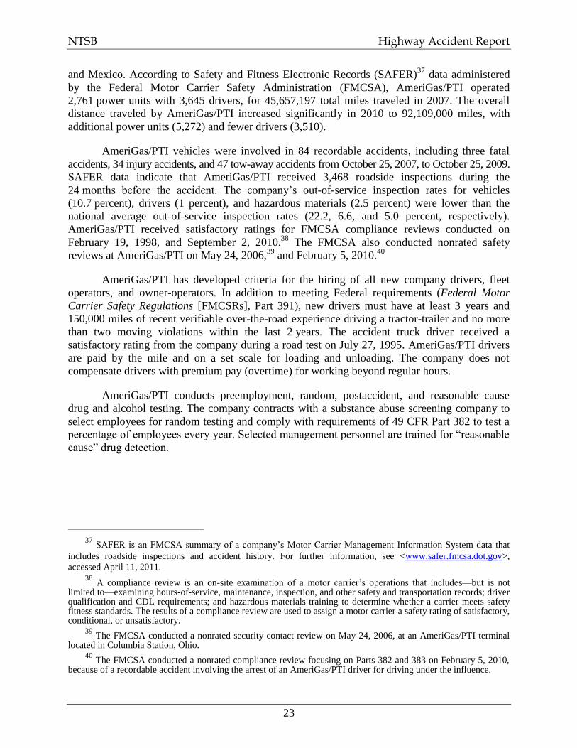
The heat of the postaccident fire damaged two outdoor advertisement signs and a
telecommunication tower (see figure 8). Eight passenger vehicles traveling on the connection
ramp and on the I-465 overpasses received minor-to-extensive heat-related damage, with two
vehicles being towed from the accident scene. Damage from the fire extended approximately
280 feet north and 110 feet south of where the cargo tank semitrailer came to rest under the I-465
overpasses.
NTSB Highway Accident Report
11
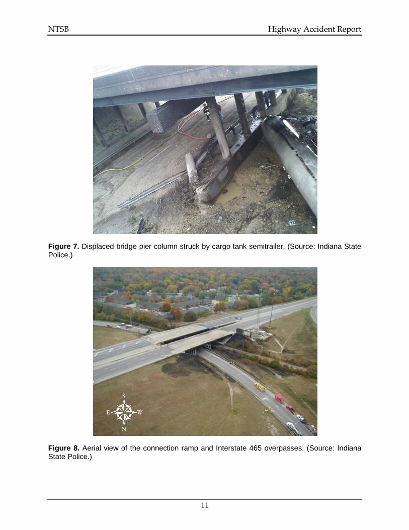
Figure 7. Displaced bridge pier column struck by cargo tank semitrailer. (Source: Indiana State Police.)
Figure 8. Aerial view of the connection ramp and Interstate 465 overpasses. (Source: Indiana State Police.)

NTSB Highway Accident Report
12
1.8 Vehicle Information (Cargo Tank Combination Unit)
The 2006 Navistar International truck-tractor and 1994 Mississippi Tank Company cargo
tank semitrailer were operated by AmeriGas Propane, L.P./Propane Transport International
(AmeriGas/PTI), which has a corporate office in King of Prussia, Pennsylvania. The five-axle
articulated combination unit was approximately 8 feet wide, with an overall length of
approximately 60 feet. NTSB investigators, together with the ISP and a representative of the
Mississippi Tank Company, conducted a postaccident examination of the combination unit.
1.8.1 Truck-Tractor
The three-axle truck-tractor, manufactured in October 2005 by Navistar International
Corporation, had a shipped weight18
when built of 16,921 pounds. The truck-tractor was
factory-equipped with a 430-horsepower (hp) Caterpillar C13 diesel engine, 10-speed manual
transmission, leaf spring suspension on the steer axle, air ride suspension on the drive axles, air
brake system with S-cam service brakes, and antilock braking system (ABS). The truck-tractor
received its last periodic inspection on May 22, 2009 (invoice date June 3, 2009), from Selking
International, Fort Wayne, Indiana. The odometer was destroyed in the postaccident fire;
maintenance records indicated an odometer reading of 268,713 miles when the truck-tractor was
serviced on October 13, 2009 (invoice date October 22, 2009), by Star Truck Rentals, Inc.,
Grand Rapids, Michigan.
Damage from the fire restricted testing on the pneumatic portion of the truck-tractor’s
braking system. All service brakes, except for the brakes on the steering axle, which were
damaged and could not be measured, were found to be within proper adjustment limits.19
The steering linkage was intact despite damage at both outboard ends and the underside
of the front axle. The steering gear (R.H. Sheppard model M100PMX3) was removed and an
internal examination was conducted in the presence of an NTSB investigator by a representative
of R.H. Sheppard Company, Inc., Hanover, Pennsylvania. The internal examination revealed
signs of excessive heat throughout the steering gear. No damage or cracks were observed on the
pitman arm splines, sector teeth, or piston teeth. In addition, no damage was observed to the
upper thrust bearing or washers, rotary valve, and lower thrust washer.
18
Shipped weight is a vehicle’s unladed dry weight with minimal or no fuel, fluids, or optional equipment. 19
The applied pushrod stroke of each brake chamber that could be measured was within the maximum applied readjustment limits specified in 49 CFR Part 396, Appendix G, and the North American Out-of-Service Criteria that are utilized by the Commercial Vehicle Safety Alliance at roadside inspections.

NTSB Highway Accident Report
13
During the accident, the truck-tractor and cargo tank semitrailer decoupled at the fifth
wheel before coming to rest. The fifth wheel coupler assembly20
was examined by
NTSB investigators and a Fontaine Fifth Wheel Company representative. Postaccident
examination revealed that the frame rails at the rear of the truck-tractor were twisted (left rail
higher than right rail), and the cross bars at the base of the mounting brackets of the fifth wheel
plate were significantly buckled and deformed (see figure 9). Signs of deformation were also
observed on the frame rails and tracks where the slide rail bracket was fastened to the rear of the
truck-tractor. The examination also found that the locks that keep the fifth wheel plate in a fixed
position on the slide rail bracket were fully engaged in the locked position. The welded stop bars
on the slide rail bracket that prevent the fifth wheel plate from inadvertently separating from the
slide rail bracket were intact and undamaged. Observations made during the examination were
consistent with the extended outboard edges of the cross bars of the fifth wheel plate becoming
deformed and the grooved section of the slide rail bracket twisting sufficiently for the fifth wheel
plate to separate from the slide rail bracket during the rollover sequence.
Figure 9. Fifth wheel plate.
In addition to separating from the slide rail bracket, the fifth wheel plate also separated
from the cargo tank semitrailer’s kingpin. The fifth wheel plate was found, with the pull handle
severely deformed, approximately 70 feet north of where the cargo tank semitrailer came to rest.
The jaw-and-wedge mechanism found in the open position at the scene and the deformation of
20
The fifth wheel coupler assembly at the rear of a truck-tractor consists of two joined components. The cross bars at the base of the fifth wheel plate (upper section) fit within metal slotted grooves on each side of the slide rail bracket (lower section). The fifth wheel plate is therefore connected to the slide rail bracket, which, in turn, is mounted to the frame rails at the rear of the truck-tractor with high-grade hexagonally shaped bolts. The fifth wheel plate is equipped with a jaw-and-wedge mechanism to allow the truck-tractor to couple to the cargo tank semitrailer’s kingpin, which serves as an anchor pin and articulation point and is located behind and under the front of the tank.

NTSB Highway Accident Report
14
the pull handle (as noted in figure 9) suggest that the pull handle became snagged as the cargo
tank semitrailer slid on its right side, allowing the fifth wheel plate to separate from the trailer
kingpin. The pull handle, located on the right side of the truck-tractor, is physically extended
outward by a driver to release the fifth wheel plate from the kingpin to decouple the truck-tractor
from the semitrailer.
The truck-tractor’s Eaton Fuller 10-speed transmission was examined to determine the
gear position at the time of the accident. The most forward of three synchronizers was observed
to be engaged in fourth or ninth gear, depending on whether the vehicle was in low or high
range, respectively. The Caterpillar C13 diesel engine had the capability, if enabled, of recording
time-series and vehicle-related speed data that may have been instrumental in reconstructing
accident events. Fire damage to the unit prevented NTSB investigators from recovering data that
may have been captured from the engine’s electronic control module.
1.8.2 Cargo Tank Semitrailer
The MC331 cargo tank semitrailer was manufactured in March 1994 by the Mississippi
Tank Company. The chassis was factory-equipped with a tandem three-leaf spring suspension
and an adjustable kingpin, which appeared undamaged. The hubometer on axle 4 displayed
298,827 miles when examined after the accident. Class 2 flammable gas placards with
identification number 1075 and the words LIQUEFIED PETROLEUM GAS were displayed on
the front, rear, and sides of the cargo tank.
The empty weight of the MC331 cargo tank semitrailer was 21,860 pounds. The bill of
lading indicated that the cargo tank was loaded with 9,001 gallons of liquefied petroleum gas
weighing approximately 37,900 pounds. The estimated weight of the combination unit laden
with 9,001 gallons of liquefied petroleum gas was 76,681 pounds.
The MC331 cargo tank was fabricated of quenched and tempered (QT)21
SA 517E steel
segments joined by butt welds that satisfied applicable American Society of Mechanical
Engineers (ASME) code requirements and Federal regulations (49 CFR 178.337). The
0.25-inch-thick hemispherical front and rear heads were each constructed from a central circular
plate and six approximately identical trapezoidally shaped gores. The tank’s shell consisted of
four 0.378-inch-thick shell sections that were cut and shaped into cylinders to match the diameter
of the head (see figure 10). The tank was 43 feet 11.5 inches long and had an inside diameter of
83.5 inches. The tank’s water capacity was 11,600 gallons, with a maximum allowable working
pressure of 250 pounds per square inch, gauge (psig).
21
Quenching is the process of heating and rapidly cooling steel to increase hardness. Tempering is a heat treatment that follows quenching to reduce the brittleness of steel without significantly lowering its hardness or strength. Quenched and tempered (QT) and nonquenched and tempered (NQT) carbon steel plate is commonly used in the construction of MC330 and MC331 cargo tanks.

NTSB Highway Accident Report
15
Figure 10. Cargo tank semitrailer (MC331).
Two X-shaped transverse baffles divided the interior volume of the MC331 cargo tank by
thirds to minimize the longitudinal surge of liquid in the tank against the front and rear heads.
The baffles were bolted to support clips and fastened to the tank shell by fillet-welded mounting
pads. Four pipe lines and fixtures used to load and unload product were contained in a steel
piping protection device. The cargo tank semitrailer was equipped with a pump to offload
product and aftermarket equipment designed to automatically close internal valves when a leak is
detected. Brake interlock devices were installed to prevent the trailer from being moved when
loading and unloading lines are connected.
Postaccident examination by the NTSB found that the head and shell cracks in the area of
impact were consistent with ductile overstress, with no indications of preexisting damage or
degradation. The majority of the cracking occurred along the fillet welds where the support
structure was attached to the tank, which is to be expected because the support structure creates
reinforcement where bending stresses are maximized. The weld geometry also introduces a stress
concentration, and the welding process could alter the microstructure of the steel to reduce the
material’s toughness. Cracking was also observed in the head of the tank within deep folds
caused by the impact with the bridge pier column, away from any fillet or butt welds.
No evidence was found of physical damage to the external piping and fittings, corrosion
pitting on the interior or exterior of the shell or heads of the tank, or weld defects in the tank
structure, such as lack of fusion. Postaccident examination of the two spring-loaded Fisher type
H732-250 pressure relief valves mounted on the top center of the tank revealed that the plastic
rain cap remained fully inserted in the forward pressure relief valve cup, but the rain cap and
specification tag for the rearmost pressure relief valve were missing.22
The internal valve stems
and springs of both valves revealed no visible signs of damage, such as corrosion, bending,
marks, or chipped paint. Postaccident bench testing determined that both valves functioned as
designed by opening within 110 percent of the maximum allowable working pressure of
250 psig.
22
The plastic cap is fully inserted into a cup located at the top of a pressure relief valve to seal and prevent rainwater from accumulating and leaking into the valve, which could lead to corrosion and affect the ability of a valve to function as designed.

NTSB Highway Accident Report
16
1.8.3 Periodic Testing and Refurbishment
Title 49 CFR Part 180.407 requires that MC330 and MC331 semitrailer pressure vessels
receive annual external visual inspections and leakage tests. Additionally, the following must be
completed every 5 years: an internal visual inspection, a wet fluorescent magnetic particle
inspection23
of all welds in and on the interior of QT and NQT cargo tanks, and a hydrostatic
pressure test. The accident vehicle’s most recent cargo tank test inspections were conducted
when the MC331 semitrailer’s chassis and cargo tank were refurbished by the Mississippi Tank
Company (Indiana Division) in July 2009. The cargo tank refurbishment included the installation
of several new components, including two pressure relief valves and a tank pressure gauge. Once
the refurbishment was completed, the wet fluorescent magnetic particle inspection and
hydrostatic pressure test were performed, and external and internal visual inspections of the tank
were conducted to check for weld defects, evidence of corrosion, abrasion, dents, and gouges.
The refurbishment of the chassis primarily involved installing new brake hardware, fabricating a
new steel plate and kingpin, and retrofitting the chassis with an ABS. The cargo tank and chassis
were sandblasted and repainted and passed all U.S. Department of Transportation (DOT)
mandated inspections.
1.9 Truck Driver Information
The truck driver was 73 years old and held a valid class ―A‖ Indiana commercial driver’s
license (CDL) with an expiration date of December 3, 2011,24
which had a restriction requiring
him to wear corrective lenses while driving. The truck driver also held endorsements for
operating a cargo tank motor vehicle and transporting hazardous materials. There were no
suspensions or disqualifications on the license. Information from the Indiana Department of
Motor Vehicles and the Commercial Driver’s License Information System (CDLIS) database
indicated that the truck driver had accumulated three moving violations during the 5 years before
the accident (see table 2). Two of the violations were for speeding, and one was for failure to
signal.
Table 2. Moving violations (2004–2009).
Violation Travel Above Posted Speed Limit
Vehicle Type Conviction Date
Failure to use/improper signal N/A Commercial vehicle October 29, 2007
Speeding* 16 mph Commercial vehicle June 7, 2007
Speeding* 17 mph Commercial vehicle May 13, 2004
*Withdrawn after the truck driver attended a safe driving course.
23
A wet fluorescent magnetic particle inspection is a nondestructive testing process for detecting surface and
near-surface flaws.
24 An Indiana CDL must be renewed every 4 years.

NTSB Highway Accident Report
17
1.9.1 Driving Experience
At the time of the accident, the truck driver had been driving heavy trucks for about
45 years, with the past 15 years spent transporting bulk liquid hazardous materials in cargo tank
motor vehicles. The truck driver said he had been involved in two accidents while driving
commercial vehicles, with the most recent occurring more than 5 years before this accident.
The truck driver had been employed by AmeriGas/PTI for about 14 years.25
He delivered
liquefied petroleum gas for AmeriGas/PTI from loading terminals in Huntington, Griffith, and
Milford, Indiana, to customer locations throughout Indiana, Illinois, and Ohio. He received
delivery assignments each day from a dispatch office in Houston, Texas, which were transmitted
to an onboard Qualcomm vehicle-tracking system26
that provided details about each load and
delivery location. Although the truck driver could be dispatched anywhere if required, most
loads were delivered within the state, allowing him to become familiar with Indiana’s network of
highways.
The truck driver was allowed to set his own work hours as long as he complied with
delivery schedules. Most working days were 14 hours. When the combination unit was not in
service, it was parked at a local AmeriGas Propane, L.P., retail facility located approximately
13 miles from the truck driver’s residence. Depending on workload, he either slept at home or in
the sleeper berth of his truck-tractor. The truck driver had been driving the same truck-tractor for
approximately 2 years before the accident occurred.
1.9.2 Medical Information
The truck driver had a 15-year history of hypertension and Type II diabetes controlled by
prescription medication. He was prescribed enalapril, hydrochlorothiazide, and atenolol to
control high blood pressure (BP) and glyburide and metformin to control blood glucose. He also
took tamsulosin to control symptoms of an enlarged prostate. The truck driver told NTSB
investigators that he tested his blood glucose level twice daily and had two pill carriers—one for
daytime and one for nighttime medication. Although he acknowledged taking all prescribed
medication at the usual times during the 3 days before the accident, he did not test his blood
glucose level on the morning that the accident occurred.
The truck driver had undergone cataract surgery on his left eye in 1995 and his right eye
in 1998. A complete ophthalmological exam in 2007 revealed no evidence of diabetic
retinopathy, and another eye exam in 2009 found the truck driver to have 20/20 corrected
distance visual acuity. The truck driver experienced an ischemic stroke approximately 10 years
25
The truck driver completed an application for employment with AmeriGas/PTI on June 23, 1995. 26
AmeriGas/PTI vehicles are equipped with a wireless communication device that provides two-way text data messaging and automatic satellite-tracking capabilities that include periodic reporting of the date, time, vehicle’s approximate location in relation to a nearby town, and status of the ignition key. Vehicle position history data can be used to locate the vehicle in real-time, later determine the route and time required to travel between two points, or review handwritten logbooks completed by commercial drivers.

NTSB Highway Accident Report
18
before the accident.27
Medical records indicate that he had a complete recovery from the stroke
except for dysarthria.28
The accident truck driver possessed a current medical certificate (signed April 21, 2009),
which expired in April 2010. The truck driver was required to be examined yearly (rather than
the typical 2-year examination period for commercial drivers)29
because of his hypertension and
diabetes.30
Commercial driver fitness examinations at AmeriGas/PTI are completed by a
physician retained by the company for that purpose. The truck driver’s most recent commercial
driver medical examination report noted his diabetes, high BP, and stroke but did not mention
any abnormalities with his extremities. An orthopedic clinic note of July 22, 2009, reported the
truck driver’s height as 72 inches and weight as 210 pounds.
The truck driver was on a 6-month medical leave in 2009 to have knee replacement
surgery for severe and painful arthritis of both knees. The right knee surgery was performed on
May 4, 2009, and the left knee on June 1, 2009. The truck driver underwent physical therapy and
was allowed by his surgeon to return to regular duties on September 28, 2009.
Postaccident hospitalization records indicated that the truck driver did not lose
consciousness, and an inpatient postaccident evaluation did not identify any neurologic or
cardiologic abnormalities that may have contributed to the accident. The truck driver’s weight
was noted as 224 pounds and his blood sugar as 258 milligrams per deciliter (mg/dL) at the time
of arrival at the emergency room. The hospital records also noted his most recent meal was at
9:45 a.m., and a laboratory record indicated his hemoglobin A1C was 6.3 percent.31
1.9.3 72-Hour History
From October 19–22, 2009, the truck driver received six loads of liquefied petroleum gas
from Dome Petroleum Corporation (the loading terminal), located approximately 2.6 miles east
of Huntington, Indiana. Five of the six loads were delivered to four locations in Indiana (see
figure 11). The one-way travel distance from the loading terminal to each of the four delivery
locations ranged from 30–133 miles.
27
Ischemic strokes account for approximately 85 percent of all stroke cases and occur when there is an
obstruction by blood clots or fatty deposits within a blood vessel that supplies blood to the brain. 28
Dysarthria is characterized by distorted speech that results from the inability to properly move the muscles of the tongue and mouth to produce speech.
29 Title 49 CFR 391.45 requires a 2-year examination cycle, unless the examining physician recommends a
shorter time period. 30
Title 49 CFR 391.43 requires a driver diagnosed with stage 1 hypertension (BP 140/90–159/99) to be certified for 1 year only. Upon recertification, if the driver’s BP is 140/90 or lower, he or she may be certified for a 1-year reexamination cycle. However, if the driver’s BP is greater than 140/90 but less than 160/100, a one-time certificate for 3 months can be issued. A driver diagnosed with stage 2 hypertension (BP 160/100–179/109) should be treated and a one-time certificate for 3 months issued. Once the driver has reduced his or her BP to 140/90 or lower, the driver may be recertified annually thereafter. A driver diagnosed with stage 3 hypertension (BP 180/110 or higher) should not be certified until his or her BP is 140/90 or lower and should be recertified every 6 months.
31 The A1C is a common blood test that reflects the average blood sugar level for the past 2–3 months.
Diabetics are recommended to maintain an A1C level below 7 percent.

NTSB Highway Accident Report
19
Figure 11. Location of loading terminal in relation to October 19–22 deliveries.

NTSB Highway Accident Report
20
A review of information recorded by the Qualcomm vehicle-tracking system revealed
that data and time-stamped information about the accident vehicle’s approximate location were
recorded approximately 80 times in the 3 days before the accident, with the first available record
generated at 11:48 a.m. near Columbia City, Indiana, on October 19, 2009, and the last at
8:44 a.m. near Chesterfield, Indiana, on October 22.
NTSB investigators utilized a software program (PC*MILER) to verify distances and the
approximate time for the truck driver to travel from the loading terminal to deliver five loads
throughout Indiana during the 3 days before the accident.32
NTSB investigators also reviewed
hours-of-service records that were provided by AmeriGas/PTI for trips that had been completed
by the truck driver in March 2009 (before the medical leave) and during the 2 weeks before the
accident. These records indicate that the truck driver worked on October 9, 12, 15, and 16, 2009,
and 3 consecutive days (October 19–21, 2009) before the accident occurred on October 22.
Hours-of-service logbooks completed by the truck driver from October 19–22, 2009,
were destroyed in the postaccident fire. Consequently, NTSB investigators obtained copies of
shipping documents, information from a postaccident interview, and Qualcomm vehicle position
history data from AmeriGas/PTI to reconstruct a 72-hour history of the truck driver’s activities
before the accident (see figure 12 and table 3). While the reconstruction of the truck driver’s
activities provides general information about his schedule, including available time for sleep, it
does not necessarily reflect the actual time that sleep was initiated or duration of sleep during the
3 nights before the accident. Based on the reconstruction of the handwritten hours-of-service
logbooks, the truck driver had driven the combination unit approximately 63 hours during 7 of
14 days from October 9–22, 2009.
Figure 12. Truck driver’s 72-hour history of activities before the accident.
32
PC*MILER is a routing and mapping software that is used by motor carriers for route navigation, rate calculation, fuel tax reporting, mileage verification, bid preparation, and freight auditing purposes.

NTSB Highway Accident Report
21
Table 3. Reconstruction of accident truck driver’s activities, October 19–22, 2009 (based on postaccident interview, shipping documents, and Qualcomm vehicle position history data).
Monday, October 19 Time (EDT) Activities Location
7:00 a.m. Awakens at residence Syracuse, IN
11:00 a.m. Begins driving Goshen, IN
12:30 p.m. On duty, loading (load #1) Huntington, IN
1:00 p.m. Begins driving Huntington, IN
2:15 p.m. On duty, unloading Ft. Wayne, IN
3:00 p.m. Begins driving Ft. Wayne, IN
4:15 p.m. On duty, loading (load #2) Huntington, IN
5:00 p.m. Begins driving Huntington, IN
8:15 p.m. On duty, unloading Lebanon, IN
8:45 p.m. Time available for sleep (3 hours 30 minutes) Lebanon, IN
Tuesday, October 20 Time (EDT) Activities Location
12:15 a.m. Begins driving Lebanon, IN
1:00 a.m. Time available for sleep (6 hours) Westfield, IN
7:00 a.m. Begins driving Westfield, IN
9:30 a.m. On duty, loading (load #3) Huntington, IN
10:00 a.m. Begins driving Huntington, IN
2:00 p.m. On duty, unloading Danville, IN
3:00 p.m. Begins driving Danville, IN
8:30 p.m. Time available for sleep (45 minutes) Huntington, IN
9:15 p.m. On duty, loading (load #4) Huntington, IN
9:45 p.m. Begins driving Huntington, IN
10:15 p.m. Time available for sleep (6 hours 45 minutes) Wabash, IN
Wednesday, October 21
Time (EDT) Activities Location
5:00 a.m. Begins driving Wabash, IN
5:30 a.m. Off duty, not driving Mexico, IN
9:00 a.m. Begins driving Mexico, IN
11:00 a.m. On duty, unloading Lebanon, IN
12:00 p.m. Begins driving Lebanon, IN
2:45 p.m. On duty, loading (load #5) Huntington, IN
4:30 p.m. Begins driving Huntington, IN
6:00 p.m. On duty, unloading Fort Recovery, OH
7:15 p.m. Begins driving Fort Recovery, OH
9:00 p.m. Time available for sleep (1 hour) Huntington, IN
10:00 p.m. On duty, loading (load #6) Huntington, IN
11:00 p.m. Begins driving Huntington, IN
Thursday, October 22
Time (EDT) Activities Location
12:00 a.m. (midnight) Time available for sleep (8 hours 15 minutes) Gaston, IN
8:15 a.m. Begins driving Gaston, IN
10:38 a.m.* Accident occurs I-69 connection to
I-465 *The accident truck driver took more than 2 hours to travel approximately 45 miles, possibly due to an
unscheduled stop between exit 45 and I-69 and the accident location. Vehicle position history data recorded by the Qualcomm vehicle-tracking system at 8:44 a.m. on October 22 and the truck driver’s last meal before the accident at approximately 9:45 a.m. (according to postaccident hospital records) suggest that he did not travel directly from a rest area at exit 45 and I-69 near Gaston, Indiana, to the accident location but instead stopped for a meal at exit 34 and I-69 near Chesterfield, Indiana.

NTSB Highway Accident Report
22
The truck driver told NTSB investigators that there were no internal or external
distractions before the accident and that he was not using the citizens band radio, manipulating
the controls of an AM/FM radio, using the Qualcomm vehicle-tracking system to send text
messages, or engaging in a cellular telephone conversation. He also said that his vision was not
temporarily obscured by sun glare nor was his concentration reduced or shifted by the large
outdoor advertising sign located directly in the line of sight of motorists traveling south on the
connection ramp. A review of the truck driver’s cellular telephone record indicated that he was
not using the telephone for talking or texting at the time of the accident.
1.9.4 Toxicology
During a postaccident interview with NTSB investigators, the truck driver indicated that
he had not consumed alcohol during the 3 days before the accident. A blood sample, taken at the
request of the ISP, was obtained from the truck driver at Clarian Methodist Hospital
approximately 3 hours after the accident (1:38 p.m.) and split into two samples. Toxicological
testing on one sample by the Indiana University Department of Pharmacology and Toxicology
did not detect alcohol or 17 other drug types.33
Toxicological testing of the other sample by the
Civil Aerospace Medical Institute (CAMI) in Oklahoma City, Oklahoma, was negative for a
wide range of legal and illegal drugs.34
The CAMI blood sample detected an antihypertensive
prescription medication, atenolol.
1.10 Motor Carrier Operations
The combination unit was operated by Propane Transport International (PTI), the
transportation division of AmeriGas Propane, L.P. PTI was established in the 1950s and operated
as a common carrier until it was acquired by AmeriGas Propane, L.P., in 1987 (referred to as
AmeriGas/PTI). AmeriGas Propane, L.P., is a subsidiary of AmeriGas Partners, L.P., a retail
propane marketer with distribution locations in 50 states.35
AmeriGas Propane, L.P. (legal name), doing business as PTI, was assigned
U.S. Department of Transportation (USDOT) number 388004 and motor carrier (MC)
number 114969.36
AmeriGas/PTI delivers bulk commodities such as propane, butane, and liquid
asphalt as a common and contract carrier within the United States, several Canadian provinces,
33
Amphetamines, barbiturates, benzodiazepines, cocaine, methadone, opiates, phencyclidine (PCP), cannabinoids (marijuana), oxycodone, opioids, LSD, fentanyl, MDMA (colloquially known as ―Ecstasy‖), propoxyphene, methqualone, buprenorphine, and ketamine.
34 Amphetamines, opiates, marijuana, cocaine, PCP, benzodiazepines, barbiturates, antidepressants,
antihistamines, meprobamate, methaqualone, and nicotine.
35 2010 Annual Report, AmeriGas Partners, L.P.
36 A USDOT number is a unique identifier used to track safety information collected during carrier audits,
compliance reviews, accident investigations, and vehicle inspections. The MC number is required to operate as a
―for-hire‖ motor carrier of regulated commodities or passengers in interstate commerce, unless the ―for-hire‖
operation is limited to transportation of exempt commodities, or the area operated within is exempt from interstate
operating authority rules (49 CFR 392.9a).
NTSB Highway Accident Report
23
and Mexico. According to Safety and Fitness Electronic Records (SAFER)37
data administered
by the Federal Motor Carrier Safety Administration (FMCSA), AmeriGas/PTI operated
2,761 power units with 3,645 drivers, for 45,657,197 total miles traveled in 2007. The overall
distance traveled by AmeriGas/PTI increased significantly in 2010 to 92,109,000 miles, with
additional power units (5,272) and fewer drivers (3,510).
AmeriGas/PTI vehicles were involved in 84 recordable accidents, including three fatal
accidents, 34 injury accidents, and 47 tow-away accidents from October 25, 2007, to October 25, 2009.
SAFER data indicate that AmeriGas/PTI received 3,468 roadside inspections during the
24 months before the accident. The company’s out-of-service inspection rates for vehicles
(10.7 percent), drivers (1 percent), and hazardous materials (2.5 percent) were lower than the
national average out-of-service inspection rates (22.2, 6.6, and 5.0 percent, respectively).
AmeriGas/PTI received satisfactory ratings for FMCSA compliance reviews conducted on
February 19, 1998, and September 2, 2010.38
The FMCSA also conducted nonrated safety
reviews at AmeriGas/PTI on May 24, 2006,39
and February 5, 2010.40
AmeriGas/PTI has developed criteria for the hiring of all new company drivers, fleet
operators, and owner-operators. In addition to meeting Federal requirements (Federal Motor
Carrier Safety Regulations [FMCSRs], Part 391), new drivers must have at least 3 years and
150,000 miles of recent verifiable over-the-road experience driving a tractor-trailer and no more
than two moving violations within the last 2 years. The accident truck driver received a
satisfactory rating from the company during a road test on July 27, 1995. AmeriGas/PTI drivers
are paid by the mile and on a set scale for loading and unloading. The company does not
compensate drivers with premium pay (overtime) for working beyond regular hours.
AmeriGas/PTI conducts preemployment, random, postaccident, and reasonable cause
drug and alcohol testing. The company contracts with a substance abuse screening company to
select employees for random testing and comply with requirements of 49 CFR Part 382 to test a
percentage of employees every year. Selected management personnel are trained for ―reasonable
cause‖ drug detection.
37
SAFER is an FMCSA summary of a company’s Motor Carrier Management Information System data that
includes roadside inspections and accident history. For further information, see <www.safer.fmcsa.dot.gov>,
accessed April 11, 2011. 38
A compliance review is an on-site examination of a motor carrier’s operations that includes—but is not limited to—examining hours-of-service, maintenance, inspection, and other safety and transportation records; driver qualification and CDL requirements; and hazardous materials training to determine whether a carrier meets safety fitness standards. The results of a compliance review are used to assign a motor carrier a safety rating of satisfactory, conditional, or unsatisfactory.
39 The FMCSA conducted a nonrated security contact review on May 24, 2006, at an AmeriGas/PTI terminal
located in Columbia Station, Ohio. 40
The FMCSA conducted a nonrated compliance review focusing on Parts 382 and 383 on February 5, 2010, because of a recordable accident involving the arrest of an AmeriGas/PTI driver for driving under the influence.

NTSB Highway Accident Report
24
1.10.1 Driver Training
AmeriGas/PTI drivers are required to attend four separate in-service training sessions
annually, lasting 8–72 hours and covering topics such as safe loading procedures and driving,
with each session requiring the driver to pass a written test. Drivers are also provided employee
training that meets the requirements of 49 CFR Part 172.41
The company has a committee that
reviews accidents and recommends remedial actions. AmeriGas Propane, L.P., management told
NTSB investigators that the company does not have a formal fatigue management program.
The company developed a Vehicle Incident Prevention Training program for preventing
backing, rear-ending, and rollover accidents. Materials to support the program include a slide
presentation, participant handbook, and instructor guide. The company also displays safety
posters and provides information in a safety bulletin about what can be done to prevent, as noted
in a company newsletter, ―an epidemic‖ of rollover accidents that have occurred in recent years,
including the rollover of 19 single-unit cargo tank trucks in 2009. Driver training handouts
identify excessive speed, inattention, and overcorrected steering as the root causes of rollovers.
The company’s training recommends that drivers not swerve to avoid an animal or debris on the
road because the inertia of the propane load could shift and lead to a rollover. Drivers were also
informed that the shifting of a partially filled tank can make a rollover situation even more likely
once the vehicle starts to tip. The accident truck driver attended the company’s rollover
awareness and prevention training and completed a Vehicle Incident Prevention Posttest on
August 15, 2008.
1.10.2 Hours-of-Service Records
AmeriGas/PTI drivers must submit handwritten logbooks to the company weekly, which
are then monitored and audited with a computer-based program (Rapid Log). Each logbook page
is reviewed for hours-of-service violations, and drivers are disciplined using a sliding scale
system if violations are found. AmeriGas/PTI provided the handwritten logs that had been
completed by the accident truck driver when he worked on October 9, 12, 15, and 16, 2009.42
The NTSB also received shipping documents and a vehicle position history report generated by
the Qualcomm vehicle-tracking system for the months of March 2009 and October 2009.43
A
detailed review that compared the truck driver’s handwritten logbook entries with shipping
documents and vehicle position history data revealed five instances of false log entries and
hours-of-service violations on 3 separate days in October 2009 (see table 4).
41
Title 49 CFR Part 172 requires that employees who work with hazardous materials receive training including general awareness/familiarization, function-specific information, emergency response procedures, hazardous materials protection, and accident prevention.
42 Title 49 CFR 395.8(K) requires the carrier to retain drivers’ records of duty (logbooks) for 6 months.
43 NTSB investigators did not receive hours-of-service records for the 6 months the driver was on medical leave
(April–September 2009).

NTSB Highway Accident Report
25
Table 4. Discrepancies between handwritten logbook and Qualcomm vehicle position history data.
Date Driver Status (handwritten log)
Truck Status (Qualcomm vehicle position
history data)*
Discrepancy
October 9, 2009 Departed Huntington, Indiana, at 1:30 p.m.
Departed Huntington, Indiana, ~1:06 p.m.
~24 minutes
Departed Noblesville, Indiana, at 6:30 p.m.
Departed Noblesville, Indiana, ~7:18 p.m.
~48 minutes
Arrived Goshen, Indiana, at 9:30 p.m.
Arrived Goshen, Indiana, ~11:05 p.m. ~95 minutes
October 12, 2009 Off duty, Goshen, Indiana, at 7:30 p.m.
Parked in White Pigeon, Michigan, ~10:01 p.m. on October 12 until ~5:06 a.m. and returned to Goshen, Indiana, ~6:18 a.m. on October 13
~642 minutes
October 15, 2009 Off duty, Huntington, Indiana, at 8:30 p.m.
Parked in New Paris, Indiana, ~7:57 p.m. on October 15 until ~5:07 a.m. and returned to Huntington, Indiana, ~10:09 a.m. on October 16
~819 minutes
*Vehicle position history data, which are captured approximately every 60 minutes, do not reflect the specific time that the combination unit departed from or arrived at a particular location.
1.10.3 Vehicle Maintenance
The 2006 International truck-tractor was leased by AmeriGas/PTI from Star Truck
Rentals in Grand Rapids, Michigan, as a new truck-tractor and brought into fleet service in
January 2006. The regular preventative maintenance on the truck-tractor was outsourced by
AmeriGas/PTI to Star Truck Rentals, Inc., in Grand Rapids, Michigan, and Donlen Corporation
in Northbrook, Illinois. The last preventative maintenance service on the truck-tractor occurred
on February 20, 2009 (invoice date February 26, 2009).
The FMCSRs require that AmeriGas/PTI and other commercial motor vehicles be
inspected annually.44
The truck-tractor received its most recent periodic inspection on May 22, 2009,
and the cargo tank semitrailer, on July 8, 2009. The most recent repairs to the truck-tractor were
performed by Star Truck Rentals, Inc., on September 18, 2009 (invoice date October 1, 2009), to
resolve an electrical problem and axle leak; and on October 13, 2009 (invoice date October 22,
2009), to install new lining and wheel seals on the steering axle, repair rear shocks, and tighten
air tanks.
Three Driver Vehicle Inspection Reports (DVIR) (October 9, 12, and 15, 2009) were
obtained from AmeriGas/PTI and reviewed. No maintenance-related concerns were noted by the
accident truck driver on these reports. DVIRs for October 19–22, 2009, were not available for
review and presumed to have been destroyed in the postaccident fire. The truck driver told NTSB
investigators that there were no mechanical problems with the combination unit on the day of the
accident.
44
Title 49 CFR 396.17 requires that all components identified in appendix G, 49 CFR Subtitle B, Subchapter B, Chapter III, be inspected yearly and that the vehicle comply with out-of-service criteria for the brake system, coupling devices, exhaust system, fuel system, lighting devices, safe loading, steering mechanism, suspension, frame, tires, wheels and rims, and windshield wipers. Documentation of this inspection must be carried in the vehicle.

NTSB Highway Accident Report
26
1.11 Highway Information
The accident occurred on an urban interstate approximately 10 miles northeast of
downtown Indianapolis, Indiana, at the I-69/I-465 interchange, on a semi-direct connection ramp
that carries the southbound lanes of I-69 to the southbound lanes of I-465 (the connection
ramp).45
The connection ramp was constructed in 1970. The twin bridges that carry the westbound
and southbound lanes of I-465 over the ramp, including the bridge pier columns that support the
superstructure and deck, were constructed in 1968. (See figure 8.) The ramp is a one-way,
two-lane roadway consisting of 12-foot-wide left and right lanes. The ramp’s paved shoulders
range from 8–9.5 feet on the right and 6–7.5 feet on the left.
The design speed for I-69 southbound approaching the connection ramp is 70 mph. The
posted regulatory speed limit for I-69 southbound north of the ramp is 55 mph. The posted speed
limit sign is on the right side of the southbound lanes of I-69, approximately 2,700 feet north of
the accident site. Approximately 0.5 mile north of the I-69 and I-465 interchange, the four
southbound lanes of I-69 expand to five lanes before splitting into two left lanes continuing south
and becoming Binford Boulevard and the three right lanes becoming a connection ramp to
channel vehicles westbound or southbound on I-465. (See figure 2.) The three lanes of the
connection ramp expand to four lanes before splitting into two right lanes curving to the right to
direct vehicles westbound on I-465 and two left lanes curving to the left to guide vehicles
southbound on I-465.
Two advisory speed limit signs posted for 50 mph are on the right side of the ramp
approximately 650 feet and 1,500 feet north of the accident site. The computed effective design
speed for the connection ramp is approximately 53 mph. Two spot-speed studies46
conducted on
the ramp by INDOT at separate locations on November 2, 2009, indicated that the 85th
percentile
speed at the first location (approximately 750 feet north of the accident site) was 56 mph for
passenger cars and 53 mph for heavy trucks. The study further indicated that the 85th
percentile
speed at the second location (approximately 2,450 feet south of the accident site) was 58 mph for
passenger cars and 55 mph for heavy trucks.
The connection ramp north of the accident location has a −0.8 percent downgrade slope.
The radius of the ramp’s leftward horizontal curve (direction of travel) is 881 feet. The ramp has
the following markings: a 6-inch-wide solid yellow line separating the left lane from the left
paved shoulder; 6-inch-wide, 10-foot-long broken white lines every 30 feet separating the left
lane from the right lane; and a 6-inch-wide solid white line separating the right lane from the
45
A semi-direct connection ramp channels vehicles from one high-speed highway to another by negotiating two curves—the first headed in a direction away from the intended route and the second gradually reversing back to connect with the other high-speed highway. For further information, see A Policy on Geometric Design of Highways and Streets, 5
th ed. (Washington, DC: American Association of State Highway and Transportation Officials, 2004),
p. 824. 46
A spot speed study uses automated methods with radar or laser speed detection equipment to measure the speed characteristics of vehicles at a specified location under the traffic and environmental conditions prevailing at the time of the study.

NTSB Highway Accident Report
27
right paved shoulder. No longitudinal rumble strips are on the ramp’s shoulders.47
The average
daily traffic on the ramp increased from 25,000 vehicles per day on April 1, 1998, to 34,000
vehicles per day on October 28, 2009. A full vehicle classification study conducted by INDOT
from October 28–30, 2009, found that traffic on the connection ramp consisted of approximately
87.5 percent passenger vehicles (class 1–3) and 12.5 percent trucks (class 4–13).48
From
2004–2008, 122 accidents occurred on the ramp, including one fatal accident in 2006.49
1.11.1. Cross-Slope Break
The cross-slope break, located at the edge of the paved traveled way or at the interface
between the traveled way and the shoulder, is calculated by taking the algebraic difference in
traverse grades between the traveled way and the shoulder. For example, a cross-slope break for
a traveled way with a positive 8 percent cross slope, sloped upward from left to right (in the
direction of travel), and a shoulder that has a negative 2 percent cross slope, sloped downward
from left to right (in the direction of travel)—such as existed in the vicinity of the connection
ramp—would be 10 percent (see figure 13).
Figure 13. Cross-slope break.
On straight roads, right shoulders are usually sloped downward to provide water drainage
away from the roadway. On curved roads, travel lanes should be sloped (superelevated) to reduce
the instability that could result in spinout or rollover accidents as vehicles negotiate curves, and
shoulders should be sloped sufficiently to prevent excessive rainwater drainage onto the traveled
way, but not so much as to create a hazard for vehicles that drive onto the shoulder.
47
Longitudinal rumble strips are raised or grooved patterns in the pavement that cause vehicles traveling over them to vibrate, alerting the driver. INDOT does not typically install longitudinal rumble strips on the shoulders of ramps.
48 The FHWA 13-category classification system includes class 1–3 vehicles, consisting of motorcycles,
passenger cars, and four-tire single unit vehicles, and class 4–13 vehicles, consisting of buses, multi-axle single-unit trucks, and articulated heavy combination vehicles.
49 The fatality resulted from a high-speed, run-off-the-road motorcycle accident.

NTSB Highway Accident Report
28
During the on-scene investigation, measurements were taken with a standard survey level
rod every 20 feet along the connection ramp up to the location where the cargo tank semitrailer
collided with the bridge pier column. These measurements found that the cross slope of the left
southbound lane varied from +7.20 to +8.27 percent, sloping upward from left to right (in the
direction of travel); the cross slope of the right southbound lane on the ramp varied from +6.58 to
+8.25 percent, sloping upward from left to right (in the direction of travel); and the cross slope of
the right shoulder varied from −1.25 to −2.75 percent, sloping downward from left to right (in
the direction of travel). Cross-slope measurements obtained on the connection ramp after the
accident indicated a cross-slope break between the right southbound lane and right shoulder
varying from 8.08–10.75 percent.
AASHTO Standards for Cross-Slope Break. The design plans for the connection ramp
developed in 1968 followed the 1957 American Association of State Highway Officials
(AASHO) A Policy on Arterial Highways in Urban Areas (commonly known as the Red Book)
and the 1965 AASHO A Policy on Geometric Design of Rural Highways (commonly known as
the Blue Book). Both the AASHO 1957 Red Book and 1965 Blue Book recommended a
maximum cross-slope break of 7 percent. Little change in the standards and philosophy of
cross-slope breaks has occurred from 1957 to the present, with the exception of a decision
published in the 2004 American Association of State Highway and Transportation Officials
(AASHTO)50
A Policy on Geometric Design of Highways and Streets51
(commonly known as the
Green Book) recommending that ―the grade break at the edge of the paved surface be limited to
approximately 8 percent.‖
Cross-Slope Break in Original Design Plans. INDOT’s original design plans for
construction of the connection ramp where this accident occurred included a +8 percent cross
slope for the left and right southbound lanes and a −4 percent cross slope for the right shoulder,
equaling a cross-slope break between the right southbound lane and right shoulder of
approximately 12 percent. Following this accident, INDOT conducted a records search to
determine why the ramp’s cross-slope break differed from the 7 percent maximum recommended
by AASHO standards developed in 1957 (Red Book) and 1965 (Blue Book).
The cross-slope break on the connection ramp was designed using a standard INDOT
ramp section sheet dated June 19, 1968,52
which appears as Sheet Number 5 on the original
design plans. The June 1968 standard INDOT ramp section sheet indicates that the ramp’s
traveled way was designed with a +8 percent cross slope and its right shoulder with a −4 percent
cross slope, corresponding to an original cross-slope break of approximately 12 percent between
the traveled way and right shoulder. The as-built plans confirmed that the cross-slope break was
constructed as shown on the original design plans. However, sometime after the connection ramp
was constructed with a 12 percent cross-slope break in 1970, the right shoulder on the ramp was
50
AASHTO (formerly AASHO) is a nonprofit, nonpartisan association representing highway and
transportation departments in the 50 states, the District of Columbia, and Puerto Rico that fosters the development,
operation, and maintenance of an integral national transportation system. 51
A Policy on Geometric Design of Highways and Streets, 5th
ed. (2004), p. 316. 52
The standard INDOT ramp section sheet dated June 19, 1968, would only have been used in situations where the traveled way was in full superelevation or +8 percent cross slope.

NTSB Highway Accident Report
29
modified by INDOT from a −4 percent cross slope, as illustrated on the original design plans for
the ramp, to a −2 percent cross slope. INDOT could not determine from available records when
the right shoulder was modified, resulting in a 10 percent cross-slope break; the agency surmised
that it occurred when the most recent work on the ramp—a 1997 pavement resurfacing project—was
conducted.
INDOT also determined from a records search that two changes occurred after the
original plans were developed in June 1968. A standard INDOT ramp section sheet, dated
August 12, 1968, illustrates the traveled way with a +8 percent cross slope and the right shoulder
with a cross slope dependent on the ramp degree of curvature. Had the ramp been designed using
the August 1968 standard INDOT ramp section sheet with a ramp curvature of 6° 30' (radius of
881 feet), the slope of the right shoulder would have been flat or zero percent. Another standard
INDOT ramp section sheet, dated October 3, 1968, illustrates the right shoulder following the
same 8 percent plane of superelevation53
as the traveled way. Had the ramp been designed and
built using the October 1968 standard INDOT ramp section sheet, the right shoulder would have
been superelevated +8 percent in the same direction as the traveled way.
INDOT records revealed that the October 1968 standard INDOT ramp section sheet was
utilized for designing cross-slope breaks on fully superelevated ramps until December 1, 1986,
when the standard drawings for typical cross-sections were developed and included in the
Indiana Design Manual, 54
which contains a list of typical applications for determining cross
slopes on shoulders based on the superelevation of the traveled way. If the ramp had been
designed today using the standards contained in the current Indiana Design Manual (January
2010), the right shoulder would have been superelevated +1 percent, resulting in a cross-slope
break between the traveled way and the right shoulder of 7 percent.
Cross-Slope Break Research. A limited Federal Highway Administration (FHWA)
study was conducted in 1981 to verify the adequacy of a maximum 7 percent cross-slope break
requirement in the 1965 AASHO Blue Book.55
A Highway-Vehicle-Object-Simulation Model
(HVOSM) was used to evaluate various cross-slope break designs by testing the effects of
curvature, speed, and path of a simulated passenger car. The simulations were performed with a
moderate (rather than shallow or severe) departure from the travel lane onto the shoulder.56
Because a moderate traversal is not a single definitive path but could be an infinite number of
paths, the study selected a nominal path that had a smaller radius than the highway curve and
permitted the simulated vehicle to come within 1.6 feet of the outside edge of the shoulder before
returning to the travel lane. The simulated vehicle traveled at the design speed, and the simulated
53
Superelevation, or cross slope, is expressed as a decimal and represents the ratio of the pavement width to elevation.
54 ―Horizontal Alignment,‖ Section 43-3.06(01) ―High-Side Shoulder,‖ Indiana Design Manual, Part 5,
Chapter 43, January 21, 2010 <http://www.in.gov/dot/div/contracts/standards/dm/2011/index.html>, accessed April 28, 2011.
55 J.C. Glennon and others, HVOSM Studies of Cross-Slope Breaks on Highway Curves, DOT-FH-11-9575
(Washington, DC: U.S. Department of Transportation, Federal Highway Administration, 1981). 56
A moderate departure onto the shoulder occurs when the vehicle could be steered back to the pavement if the shoulder is wide enough, and the cross-slope break and shoulder slope do not cause the vehicle to exceed available skid resistance or result in intolerable centrifugal force on the driver.

NTSB Highway Accident Report
30
driver released its foot from the accelerator pedal at the first point of encounter with the
cross-slope break.
A series of HVOSM runs were performed to compare the dynamic differences between
partial (straddling with right side wheels only) and full placement (entire vehicle) traversals onto
the shoulder. A maximum 0.3 g lateral acceleration for driver discomfort was established, which
was considered to be the level of apprehension most drivers could withstand during shoulder
traversals without the driver subsequently initiating a hard brake application or excessive steer
input that could result in a loss of control maneuver. The 0.3 g criterion was found to correspond
with the 1965 AASHO Blue Book recommendation for a maximum 7 percent cross-slope break.
The four-wheel traversals onto the shoulder (rather than two-wheel traversals) produced
the most extreme dynamic responses. Driver discomfort mainly increased with shoulder slope
and very little, if any, with the amount of cross-slope break. Thus, for a given design speed and
superelevation of a horizontal curve, the maximum tolerable cross-slope break was a function of
the shoulder cross slope. The most important conclusion from the study (according to the
authors) is that for a negative shoulder cross slope to be tolerable for a recovery maneuver, it
should be designed with just the minimum cross slope necessary to keep water from pooling in
the travel lanes.
1.11.2 Protection of Bridge Pier Columns
The support structure for the southbound I-465 overpass consisted of a concrete bridge
footing (crash wall), seven concrete cylindrical pier columns, and a pier cap. The bridge footing
was raised approximately 1.5 feet from the ground. The reinforced pier columns were 24 inches
in diameter and stood approximately 14.3 feet high, as measured from the top of the bridge
footing to the bottom of the pier cap. The outermost bridge pier column on the southbound I-465
overpass, which was struck by the cargo tank, was the first in a row of seven uniformly spaced
columns approximately 10 feet on center.
Strong post blocked-out W-beam guardrails were located on both sides of the connection
ramp adjacent to the paved shoulders to protect the bridge pier columns from vehicle impacts.
The strong posts that were connected to the steel W-beam rail element consisted of steel I-beams
spaced 6.25 feet apart and embedded approximately 4–5 feet in the ground. The W-beam rail
element was extended away (blocked out) from the posts with steel or timber spacer blocks. The
W-beam guardrail was 30 inches tall, as measured from the pavement surface to the top of the
W-beam rail element. The W-beam guardrail on the right side of the ramp began approximately
340 feet north of the I-465 overpasses, and the W-beam guardrail on the left side, approximately
930 feet. The concrete bridge pier column impacted by the semitrailer was offset from the
W-beam guardrail by approximately 6 feet (see figure 14).

NTSB Highway Accident Report
31
Figure 14. Bridge pier column protection (before accident).
Temporary construction shoring was erected after the accident behind the bridge pier
column to provide vertical support for the three outside beam lines of the southbound I-465
overpass. A reinforced concrete wall, measuring approximately 14 feet high by 12 feet long by
2 feet wide, was then erected between the bridge footing and pier cap to fill the void space
created after the bridge pier column was struck. I-465 remained closed to traffic for at least 1 day
after the accident. The connection ramp was reopened on October 27, 2009.
AASHTO Standards. Since the adoption of the first AASHO specifications in 1931, the
body of knowledge in bridge research and design has grown significantly. The most recent
framework—Load and Resistance Factor Design (LRFD) Bridge Design Specifications—utilizes
state-of-the-art analysis and design methodologies and makes use of load and resistance factors
based on the known variability of applied loads and material properties.57
A phased approach
was taken to implement the requirements of LRFD Bridge Design Specifications, with a
transition schedule extending from 1994–2007. All five editions of the LRFD Bridge Design
Specifications58
contain similar provisions for bridge pier protection, with the most recent edition
published by AASHTO in 2010. AASHTO and the FHWA determined that, after
October 1, 2007, all new bridges and replacements of existing bridges should be designed using
the most current edition of the LRFD Bridge Design Specifications,59
which requires that bridge
pier columns be protected if located within an area that extends approximately 30 feet from the
edge of the traveled way (clear zone). Further, obstacles located within the clear zone should be
removed, relocated, redesigned, or shielded by traffic barriers or crash cushions.
57
LRFD Implementation Plan, Initial Draft, Federal Highway Administration. <http://www.fhwa.dot.gov/bridge/lrfd/plan.cfm>, accessed June 22, 2011.
58 Publication dates for the LRFD Bridge Design Specifications are as follows: 1
st ed. (1994), 2
nd ed. (1998), 3
rd
ed. (2004), 4th
ed. (2007), and 5th
ed. (2010). 59
Design Standards for Highways, 23 CFR Part 625.

NTSB Highway Accident Report
32
The Transportation Research Board (TRB) National Cooperative Highway Research
Program (NCHRP) has established the following criteria for barrier protection testing:60
Test levels 1–3 (TL-1, TL-2, and TL-3): An 1,800-pound car striking a barrier at
a 20° angle and a 4,400-pound pickup truck striking a barrier at a 25° angle at
speeds of 30 mph (TL-1), 45 mph (TL-2), and 60 mph (TL-3), respectively.
Test level 4 (TL-4): A 17,600-pound single-unit truck striking a barrier at an
angle of 15° at 50 mph.
Test level (TL-5): An 80,000-pound truck-tractor and a van-type semitrailer
striking a barrier at an angle of 15° at 50 mph.
Test level (TL-6): An 80,000-pound truck-tractor and a cargo tank semitrailer
striking a barrier at an angle of 15° at 50 mph.
Minimum height requirements for bridge railings, which are contained in the AASHTO
LRFD Bridge Design Specifications, are as follows: TL-1, TL-2, and TL-3 barriers—27 inches;
TL-4 barrier—32 inches; TL-5 barrier—42 inches; and TL-6 barrier—90 inches.
Bridge pier columns in the clear zone can be protected by either providing structural
resistance to the bridge pier column or by redirecting or absorbing an impact from an errant
vehicle. The option to redirect or absorb can be provided with an embankment or a 54-inch-high
concrete barrier if the bridge pier column is located within 10 feet of the edge of the traveled way
or a 42-inch-high concrete barrier if the bridge pier column is located more than 10 feet but less
than 30 feet from the edge of the traveled way.61
These barriers must be structurally and
geometrically capable of withstanding the impact specified for a TL-5 barrier. The option to
provide structural resistance requires that the bridge pier column be designed for an equivalent
static force of 400 kips62
(400,000 pounds), acting in any direction in a horizontal plane at a
distance of 4 feet above the ground. Based on the results of a Transportation Pooled Fund
Program63
study entitled Guidelines for Designing Bridge Piers and Abutments for Vehicle
Collisions,64
a recommendation was made to AASHTO’s Subcommittee on Bridges and
Structures in May 2010 that the equivalent static force of 400 kips be increased to 600 kips.
New and Replacement Bridges. The LRFD Bridge Design Specifications contain
Federal requirements for the protection of bridge pier columns on approximately 500 new and
replacement bridges built in the United States each year (see table 5).65
This new construction
60
Recommended Procedures for the Safety Performance Evaluation of Highway Features, NCHRP Report 350 (Washington, DC: Transportation Research Board, 1993).
61 The requirements of AASHTO LRFD Bridge Design Specifications for protecting bridge pier columns differ
and are independent from test levels for roadside barriers.
62 A kip is a unit of force equaling 1,000 pounds.
63 A Transportation Pooled Fund Program study is generally conducted to solve transportation-related problems
with significant or widespread interest and may be funded jointly by several Federal, state, regional, and local transportation agencies. The Texas Department of Transportation was the sponsoring agency for this study.
64 Guidelines for Designing Bridge Piers and Abutments for Vehicle Collisions (College Station, Texas: Texas
Transportation Institute, Texas A&M University, December 2009). 65
FHWA Office of Bridge Technology, e-mail to the NTSB (November 17, 2010).

NTSB Highway Accident Report
33
represents a small percentage of the approximately 41,000 bridges in the United States66
with a
roadway passing underneath bridge spans, where intermediate columns are subject to vehicle
impacts.67
Table 5. New and replacement of bridges built in the United States, 2005–2009.
Year New and Replacement Bridges
2009 476
2008 640
2007 540
2006 597
2005 548
The AASHTO Roadside Design Guide provides guidance to highway agencies on the use
of roadside barriers to protect bridge pier columns that are part of new projects and major
projects involving the addition of a lane, significant changes to a roadway’s horizontal or vertical
alignment, or reconstruction of an interchange. The 2006 Roadside Design Guide does not
contain objective warrants but suggests that higher performance traffic barriers (TL-4 and above)
be utilized at locations with above-average heavy truck traffic, adverse geometrics with poor
sight distance, or severe consequences associated with the penetration of a barrier by a large
vehicle.
Existing Bridges. Although AASHTO’s LRFD Bridge Design Specifications and
Roadside Design Guide are adequate for planned highway improvements, documentation is
limited for assessing the protection of bridge pier columns on existing bridges not scheduled for
construction. The FHWA Office of Bridge Technology did indicate, however, that the criteria
contained in the LRFD Bridge Design Specifications, which specifies minimum requirements for
new bridges, may also be used by bridge owners to evaluate existing bridges,68
including
structures and piers.
An inventory conducted by INDOT on December 3, 2009, of all direct and semi-direct
connection ramps and roadside bridge pier protection revealed that approximately 44 direct or
semi-direct connection ramps were classified as underpasses69
in Indiana and each had some type
of roadside barrier for protecting bridge pier columns. The level of protection varied from a
W-beam guardrail (TL-3) to a concrete barrier (TL-4 or TL-5).
INDOT indicated that ramps in Indiana cannot be systematically ranked in terms of
traffic safety performance when a systemwide evaluation of roads is conducted because the large
number of accidents on ramps makes it impossible to assign precise latitude and longitude
coordinates. This limitation restricts the ability to compare accidents that occur on a particular
66
New and replacement bridges or other structures are built because of substandard load-carrying capacity or substandard bridge roadway geometry (FHWA Office of Safety e-mail to the NTSB, November 4, 2010).
67 The National Bridge Inventory, which aggregates structure inventory and appraisal data collected by each
state, consists of approximately 600,000 bridges. 68
FHWA Office of Bridge Technology e-mail to the NTSB (December 9, 2010). 69
Underpasses are considered direct or semi-direct connection ramps when the ramp is carried under another roadway, rather than over.

NTSB Highway Accident Report
34
ramp with other types of ramps or road segments, road intersections, and road interchanges. To
address this circumstance unique to ramps, INDOT plans to use supplementary analysis to gauge
the performance of ramps when it conducts future evaluations of the traffic safety performance
of its road system. The objective of such analysis will be to identify ramps operating poorly so
that they can be improved with infrastructure or engineering treatments, modification of traffic
control devices, enforcement, or other measures.70
1.12 Cargo Tank Motor Vehicles
Cargo tank motor vehicles represented 8.3 percent of the national fleet with five axles or
more in 1997; approximately 80 percent of these vehicles transport bulk liquids or gases and
approximately 20 percent, dry bulk materials.71
About 85 percent of all tractor-semitrailers
traveling with hazardous materials are cargo tank motor vehicles; the remainder are van-type
semitrailers.72
1.12.1 DOT Specification Cargo Tanks
Federal regulations for the design and construction of cargo tanks that transport bulk
liquid hazardous materials (―DOT specification cargo tanks‖) are established by the Pipeline and
Hazardous Materials Safety Administration (PHMSA). Design requirements for cargo tanks
contained in 49 CFR Part 178 (specifications for packaging) are supported by ASME standards.
Testing and inspection requirements for cargo tanks are contained in 49 CFR Part 180
(continuing qualification for maintenance of packaging). Depending on the specification of the
cargo tank, the following tests and inspections are required either annually or every 5 years:
periodic external and internal visual inspection, lining inspection, leakage testing, thickness
testing, wet fluorescent magnetic particle inspection of interior welds, and a hydrostatic pressure
test.
The MC331 cargo tank and its predecessor, the MC330, transport liquefied compressed
gases73
in a smooth-bore (single) compartment, noninsulated, straight round cargo tank with
hemispherical (half dome) or torispherical (shallow dome) heads and a maximum allowable
working pressure between 100 and 500 psig. The average useful life of an MC331 cargo tank
ranges from 25–50 years.74
MC330 cargo tanks, which were last manufactured in 1965, still
70
INDOT Director of Bridge Design, Inspection, Hydraulics, and Technical Support, response (September 2, 2010) to a question during the August 2010 NTSB public hearing on the Indianapolis rollover accident. For further information, see ―Rollover and Fire of a Truck-Tractor and Cargo Tank Semitrailer Carrying Liquefied Petroleum Gas in Indianapolis, Indiana, October 22, 2009,‖ public hearing, Washington, DC, August 3–4, 2010 <http://www.ntsb.gov/events/2010/Indianapolis-IN/Default.html>, accessed June, 22, 2011.
71 Analysis of the Vehicle Inventory and Use Survey for Trucks with Five-Axles or More (Washington, DC:
U.S. Department of Transportation, Federal Highway Administration, May 2001). 72
K.L. Campbell, National Estimates of the Number of Trucks, Travel, and Accident Experience of Tractor Semitrailers Used to Transport Hazardous Materials, Report No. UMTRI-89-1 (Ann Arbor, Michigan: University of Michigan Transportation Research Institute, 1989).
73 Compressed gases such as propane, butane, anhydrous ammonia, chlorine, and sulphur dioxide are
transported in a liquid form under pressure. 74
Testimony delivered by cargo tank manufacturers on August 4, 2010, at the NTSB public hearing concerning the Indianapolis rollover accident.

NTSB Highway Accident Report
35
represent approximately 15–20 percent of the cargo tanks currently transporting liquefied
compressed flammable gases.75
The most common articulated commercial motor vehicle for
transporting liquefied petroleum gas is a three-axle truck-tractor and two-axle cargo tank semitrailer,
the type of combination unit involved in this accident.
1.12.2 Crashworthiness of DOT Specification Cargo Tanks
The NTSB examined the crashworthiness of DOT specification cargo tanks in its
investigation of a 1994 accident76
involving a cargo tank motor vehicle rollover. In that accident,
a truck-tractor in combination with a specification MC331 cargo tank semitrailer transporting
9,200 gallons of liquefied petroleum gas, drifted across the left lane and left shoulder, struck a
guardrail, rolled over, and collided with a cylindrically shaped concrete bridge pier column. The
front head of the tank fractured, releasing liquefied petroleum gas, which vaporized and ignited.
The blast propelled the tank approximately 300 feet onto a wood-framed house. The driver was
killed, 23 people were injured, and an area with a radius of approximately 400 feet was engulfed
by fire. As a result of its investigation, the NTSB issued the following recommendation to the
Research and Special Programs Administration (RSPA)77
:
In cooperation with the Federal Highway Administration, study methods and
develop standards to improve the crashworthiness of front heads on cargo tanks
used to transport liquefied flammable gases and potentially lethal nonflammable
compressed gases. (H-95-37)
The recommendation prompted RSPA to sponsor two studies to determine the response
of MC331 cargo tank heads when striking various obstacles and the effect of head shielding on
improving the crashworthiness of cargo tanks in various impact scenarios. The first study
established a correlation between analytical models and damage resulting from actual accidents,
examined failure criteria for the puncture of unprotected heads and those with a full or partial
shield, compared the shape and thickness of heads to determine practical designs for unprotected
heads, and evaluated head shielding at various distances and energy-absorbing material.78
The
work involved developing a three-dimensional finite element model to determine the speed at
which the unprotected hemispherically shaped front head of an MC331—similar to the cargo
tank involved in the White Plains, New York, accident—would fail during four accident
scenarios: (1) frontal impact with a rigid wall, (2) angled impact at 45° into a rigid wall,
(3) impact into a 6-inch-diameter immovable circular post, and (4) impact with the tank rotated
onto its side into a 42-inch-diameter cylindrical column. The models indicated that the front head
75
Testimony delivered by Mike Pitts, Vice-President, Sales, Mississippi Tank Company, on August 4, 2010, at the NTSB public hearing concerning the Indianapolis rollover accident.
76 Propane Truck Collision with Bridge Column and Fire, White Plains, New York, July 27, 1994, Highway
Accident Report NTSB/HAR-95/02 (Washington, DC: National Transportation Safety Board, 1995). 77
Within DOT, RSPA was reorganized in 2004 into PHMSA and the Research and Innovative Technology Administration.
78 A. Selz and C.F. Heberling, Pressure Sciences Incorporated, Improving Crashworthiness of Front Head of
MC331 Cargo Tank Motor Vehicles (Washington, DC: Research and Special Programs Administration, February 2000).

NTSB Highway Accident Report
36
would fail at approximately 25 mph after striking a rigid wall and at less than 15 mph after
impacting a 42-inch-diameter concrete column.
Despite concerns about the adequacy of minimum construction requirements allowing the
front head to be thinner than the tank shell, researchers were surprised to find that the thicker
hemispherical head—as revealed by the models—had a lower failure speed than the thinner one
when both struck a rigid wall; and, furthermore, that the 0.25-inch and 0.378-inch-thick
hemispherical front heads of the cargo tanks both failed at impact speeds below 15 mph when a
cylindrical concrete column was struck. The study results indicated that protection against angled
impacts into rigid surfaces or collisions with bridge pier columns may be enhanced by placing
energy-absorbing material between the front head and a secondary head on the MC331 cargo
tank. Researchers recommended that a cost-benefit analysis be conducted for a conceptual head
shielding design to improve the crashworthiness of MC331 cargo tanks.
The second study sponsored by RSPA evaluated the feasibility, manufacturing costs, and
marketability considerations for reducing the probability of fractures and/or penetrations to the
front heads and adjacent structure of the MC331 cargo tank.79
Finite element models were again
used to evaluate different approaches to protect the front heads of MC331 cargo tanks. Various
densities and thicknesses of foam were examined to determine which configuration of
energy-absorbing material would prevent a cargo tank from rupturing during a collision. It was
determined that a foam thickness of 18 inches would protect the front head of the tank from
failure during a 45° angle impact into a rigid wall at 52 mph and into a rigid 42-inch-diameter
column at up to 59 mph. The estimated cost of installing an 18-inch-thick layer of
energy-absorbing foam covered with a 0.060-inch-thick layer of sheet steel over the head of an
MC331 cargo tank was $27,939 per trailer. The study concluded that although the modification
would protect the tank from failure during the crash and impact scenarios that were studied, at
speeds up to approximately 55 mph, the increased manufacturing cost and weight of
4,376 pounds of additional material for each cargo tank would not be cost effective.
In an August 18, 2003, letter to the Acting Administrator, RSPA, the NTSB
acknowledged the cost constraints of improving cargo tank crashworthiness but also asserted that
crashworthiness remains a critical issue for cargo tanks transporting liquefied petroleum gas,
with the concomitant potential for flammable gas explosions, toxic gas releases, and rocketing of
cargo tanks. Consequently, Safety Recommendation H-95-37 and its companion
recommendation to the FHWA, H-95-35, were classified ―Closed—Unacceptable Action.‖
1.12.3 Hazardous Materials Carrier Registration
An objective assessment of DOT specification cargo tank involvement in reportable
incidents requires access to accurate information about the population of cargo tanks by DOT
specification. Information associated with the operation of DOT specification cargo tanks is
collected and maintained by the FMCSA and PHMSA. According to the FMCSA, approximately
79
A. Selz and P. Burnside, Pressure Sciences Incorporated, Further Work to Improve Crashworthiness of Front Head of MC331 Cargo Tank Motor Vehicles (Washington, DC: Research and Special Programs Administration, March 2001).

NTSB Highway Accident Report
37
6,500 motor carriers operate a fleet of cargo tank motor vehicles that transport liquefied
petroleum gas.80
The FMCSA registration process requires all interstate motor carriers, commercial motor
vehicle registrants from select states, and commercial intrastate hazardous materials carriers
hauling quantities requiring a safety permit to complete and submit a Motor Carrier
Identification Report (MCS-150) to obtain a USDOT number. Carriers are also required to file
biennial updates to report changes in operations, including the number of vehicles operated in the
United States. Data contained on the MCS-150 form are stored in the Motor Carrier Management
Information System (MCMIS), a system of databases containing information from field offices
and other sources. These data include police-reported accidents involving cargo tank motor
vehicles in which no release of hazardous materials occurred. MCMIS is a source of inspection,
crash, compliance review, safety audit, and registration data.
Since 1992, PHMSA has required entities transporting certain hazardous materials,
including hazardous wastes, to submit a Hazardous Materials Registration Statement (DOT
Form F 5800.2) and pay an annual registration fee. DOT Form F 5800.2 requests the identity of
the hazardous materials carrier, the mode(s) of transportation used, business category, basic
description of hazardous materials activity, and states where operations are conducted.
Registration fees collected from hazardous materials carriers provide funding for grants
distributed to states and other professional organizations for hazardous materials emergency
response planning and for training through the Hazardous Materials Emergency Preparedness
Grants Program.
1.12.4 Rollover Awareness
More than 1,300 rollovers involving cargo tank motor vehicles occur yearly in the
United States.81
Approximately 60 percent of these rollovers involve semitrailers and 40 percent,
single-unit trucks.82
The rollover rate of cargo tank semitrailers is more than double that of all
other semitrailers.83
Rollovers occur in 24 percent of all hazardous material accidents and
account for 75 percent of all spills.84
About 50 percent of truck driver deaths and 47 percent of
80
―Effectiveness of Driver Training for Preventing Rollover Accidents,‖ PowerPoint presentation delivered by James O. Simmons, FMCSA, on August 3, 2010, at the NTSB public hearing concerning the Indianapolis rollover accident.
81 ―Tank Truck Drivers: This Sign’s for You!‖ Safety News (Washington, DC: U.S. Department of
Transportation, Federal Motor Carrier Safety Administration, May 13, 2008). 82
D.B. Pape and others, Battelle, Cargo Tank Roll Stability Study, final report, contract no. GS23-F-0011L (Washington, DC: U.S. Department of Transportation, Federal Motor Carrier Safety Administration, April 30, 2007).
83 UMTRI-89-1.
84 Hazardous Materials Serious Crash Analysis: Phase 2, final report (Washington, DC: U.S. Department of
Transportation, Federal Motor Carrier Safety Administration, April 2005).

NTSB Highway Accident Report
38
incapacitating injuries occur from rollovers.85
Driver error (such as decision or recognition error)
was found to be a factor in approximately 75 percent of cargo tank rollovers.86
Government and industry have been involved in a number of rollover awareness
initiatives. In 2005, the National Tank Truck Carriers (NTTC) partnered with J.J. Keller &
Associates, Inc., to develop an educational campaign consisting of a monthly poster, fact sheet,
and payroll stuffers to raise the awareness of drivers on how to prevent cargo tank rollovers.87
In
2006, the FMCSA sponsored a Cargo Tank Roll Stability Study to learn more about the factors
contributing to and strategies for reducing cargo tank rollovers.88
The study examined how
rollovers can be reduced by outfitting cargo tank motor vehicles with stability control systems,
enhancing the basic roll stability of cargo tank motor vehicles, employing strategies to address
difficult geometric and surface challenges, and improving driver training. The Cargo Tank Roll
Stability Study concluded that although the tasks of safely operating a cargo tank motor vehicle
are essentially the same as those for operating other class A heavy trucks, they must be mastered
to a greater proficiency. To date, traditional approaches for raising cargo tank vehicle driver
skills, such as disseminating instructional materials, have been employed in this effort. For
example, the FHWA’s Office of Motor Carriers (predecessor to the FMCSA) has issued
educational materials on the skills required for operating and controlling cargo tank motor
vehicles through its On Guard bulletins.
Following its investigation of a 1991 tractor-semitrailer (cargo tank) rollover,89
the NTSB
issued the following recommendation to the FHWA:
Issue periodic On Guard bulletins to remind all carriers and drivers to be attentive
and aware of the conditions that can lead to a loss of stability and rollover in a
tank truck. (H-91-33)
In response to the recommendation, the FHWA published two additional safety bulletins,
in August 1992 and March 1995, in addition to one previously published in June 1980 on cargo
tank motor vehicle safety,90
to remind drivers about the need to review the special handling
requirements for cargo tank motor vehicles with partial loads. Because the FHWA had published
several On Guard bulletins since 1980 regarding the loss of stability and potential for rollover of
cargo tank motor vehicles and stated it would continue to publish future bulletins if necessary,
the NTSB classified Safety Recommendation H-91-33 ―Closed—Exceeds Recommended
Action‖ on June 24, 1996.
85
1995 Truck and Bus Crash Fact Book, Report No. UMTRI-97-30 (Ann Arbor, Michigan: Center for National Truck Statistics, University of Michigan Transportation Research Institute, 1997).
86 Cargo Tank Roll Stability Study.
87 ―NTTC, J.J. Keller Launch Anti-Rollover Campaign,‖ Bulk Transporter, June 1, 2005.
88 Cargo Tank Roll Stability Study.
89 Overturn of a Tractor-Semitrailer (Cargo Tank) With Release of Automotive Gasoline and Fire, Carmichael,
California, February 13, 1991, Hazardous Materials Accident Report NTSB/HZM-91/01 (Washington, DC: National Transportation Safety Board, 1991).
90 ―Anything Other Than Full or Empty,‖ On Guard (Washington, DC: Office of Motor Carriers, Federal
Highway Administration, June 1980, August 1992, and March 1995).

NTSB Highway Accident Report
39
In late 2007, the FMCSA scheduled a series of Tank Truck Rollover Prevention Summits
to discuss and review approaches for rollover reduction and develop training and management
materials.91 To further address the problem, the FMCSA, in association with PHMSA and
industry partners, created a Cargo Tank Driver Rollover Prevention Video, which was released
on August 3, 2010, to serve as a training aid for commercial drivers of cargo tank motor vehicles
transporting hazardous materials.
The long-term effectiveness of traditional approaches (such as brochures and videos) for
raising driver awareness of rollover prevention strategies is generally unknown. A study
currently under development by the TRB, Role of Human Factors in Preventing Cargo Tank
Truck Rollovers, which seeks to identify and analyze the root causes of cargo tank rollovers, may
provide greater insight on increasing the awareness of drivers about actions necessary to prevent
the rollover of cargo tank motor vehicles.92
A Heavy Vehicle Rollover Prevention Program introduced by VicRoads93
to
approximately 5,000 commercial drivers in July 2009 was effective in reducing rollover
accidents. The program used truck models to visually demonstrate the effect of CG height on
heavy commercial truck rollovers and encouraged motor carriers to develop a written code of
behavior on the shared role of drivers and management in developing workable solutions for
preventing rollover accidents, as opposed to merely presenting driver- or management-driven
objectives. The program operated with the understanding that management would reduce the risk
of rollovers by purchasing trailers with as low a CG height as practical, selecting routes to avoid
high risk locations, and monitoring drivers’ schedules to prevent fatigue.
1.13 Vehicle-Based Rollover Prevention
Two primary vehicle-related approaches are available to prevent cargo tank motor
vehicle rollovers. One approach involves equipping vehicles with stability control systems to
reduce ―untripped‖ rollovers94
resulting from excessive speed in a curve, which represent
approximately 10–15 percent of rollovers involving cargo tank motor vehicles. The second
approach involves vehicle design strategies for improving roll stability to reduce the number of
tripped and untripped rollovers.
1.13.1 Stability Control Systems
The NTSB has long advocated the study and implementation of advanced crash
avoidance technologies to assist drivers in maintaining control of commercial motor vehicles.
91
―Tank Truck Rollover Prevention Summits,‖ Bulk Transporter, October 1, 2007. 92
The study was initiated in October 2010, with a final report anticipated in January 2012. 93
VicRoads is a statutory authority of the State of Victoria in the Commonwealth of Australia. For further information, see Heavy Vehicle Rollover Prevention Program, VicRoads, Australia <http://www.vicroads.vic.gov.au/truckrollover>, accessed May 1, 2011.
94 Untripped rollovers occur when tire/road interface friction is the only external force acting on a vehicle that
rolls over. In contrast, tripped rollovers are caused when vehicles impact curbs, potholes, and guardrails or when wheel rims burrow into soft soil or pavement.

NTSB Highway Accident Report
40
For example, in its investigation of a multiple-fatality mid-size bus rollover accident that
occurred in Dolan Springs, Arizona, in January 2009,95
the NTSB addressed the benefits of
equipping buses with a gross vehicle weight rating (GVWR) greater than 10,000 pounds with
stability control systems. As a result of that investigation, the NTSB issued the following
recommendations to NHTSA:
Develop stability control system performance standards applicable to newly
manufactured buses with a gross vehicle weight rating above 10,000 pounds.
(H-10-5)
Once the performance standards from Safety Recommendation H-10-5 have been
developed, require the installation of stability control systems in all newly
manufactured buses in which this technology could have a safety benefit.
(H-10-6)
In November 2009, NHTSA announced the availability96
of its Final Vehicle Safety
Rulemaking and Research Priority Plan for 2009–2011,97
which indicated test procedures would
be developed to support a stability control standard for truck-tractors. The planned research
involves testing rollover stability control (RSC) systems and electronic stability control (ESC)
systems for heavy trucks and vehicles greater than 10,000 pounds GVWR, including
truck-tractors, single-unit trucks, buses, and motorcoaches. In its initial response since
Safety Recommendations H-10-5 and -6 were issued in July 2010, NHTSA indicated to the
NTSB that efforts were underway to develop test procedures supporting a potential standard on
ESC systems.
In March 2011, NHTSA published a notice to announce the availability of its Final
Vehicle Safety Rulemaking and Research Priority Plan 2011–2013,98
which was developed to
apprise the public on the status of efforts delineated in the October 2009–2011 plan. The next
milestone in the 2011–2013 plan for developing stability control systems to address rollover and
loss-of-control accidents is a notice of proposed rulemaking in 2011, which will contain test
procedures for truck-tractors and motorcoaches.99
NHTSA also plans to make a decision in 2014
about developing test procedures as part of a stability control standard for trucks, buses, and all
other vehicles greater than 10,000 pounds GVWR that are not included in the truck-tractor and
motorcoach rulemaking activity. Therefore, pending the completion of these recommended
actions, Safety Recommendations H-10-5 and -6 were reclassified ―Open—Acceptable
Response.‖
95
Bus Loss of Control and Rollover, Dolan Springs, Arizona, January 30, 2009, Highway Accident Report NTSB/HAR-10/01 (Washington, DC: National Transportation Safety Board, 2010).
96 Federal Register, vol. 74, no. 215 (November 9, 2009), p. 57623.
97 Final Notice Rulemaking and Research Priority Plan 2009–2011, National Highway Traffic Safety
Administration, Document ID Number 2009-0108-0022, <http://www.regulations.gov/search/Regs/home.html#documentDetail?R=0900006480a53424>, accessed May 1, 2011.
98 Federal Register, vol. 76, no. 62 (March 31, 2011), p. 17808.
99 NHTSA Vehicle Safety and Fuel Economy Rulemaking and Research Priority Plan 2011–2013, March 2011.

NTSB Highway Accident Report
41
The benefits of stability control systems for passenger cars have been recognized for
several years. A study using National Accident Sampling System (NASS) General Estimates
System (GES) data from NHTSA to analyze different makes and models, but similar model
years (MYs), of passenger vehicles found that by installing ESC systems, loss-of-control
accidents could be reduced approximately 40.3 percent for cars and 71.5 percent for sport utility
vehicles.100
In addition, NHTSA issued a final rule in April 2007 requiring the installation of
ESC in 100 percent of light vehicles with a GVWR of 10,000 pounds or less by MY 2012
(except some vehicles manufactured in stages or by small volume manufacturers).101
ESC
systems are becoming increasingly common standard equipment in passenger vehicles—an
estimated 71 percent of MY 2010 light vehicles sold in the United States were equipped with
ESC.
Stability control systems are an emerging technology that also holds promise for reducing
heavy commercial motor vehicle accidents by preventing untripped rollovers (excessive speed in
a curve), mitigating severe oversteer and understeer conditions that could lead to loss of control,
and providing objective feedback to assist carriers monitor and improve driver performance.
NHTSA has conducted field operational tests and several studies since 1998 to examine the
effectiveness and safety benefits of active safety systems for enhancing the dynamic stability of
heavy truck operations. Two stability control systems, tractor- or trailer-based RSC systems and
tractor-based ESC, have been developed for commercial motor vehicles. RSC systems use
accelerometers to continually monitor and compare the lateral acceleration of vehicles to a
known critical rollover threshold. When the threshold has been reached, a tractor-based RSC
system automatically reduces delivery of fuel to the engine and applies the foundation brakes on
the drive axles and trailer to slow the speed of the vehicle in a curve. A trailer-based RSC system
only applies the foundation brakes on the trailer when a critical rollover threshold has been
detected. RSC is designed to prevent ―untripped‖ rollovers in which the speed of a vehicle
entering a curve is too fast.102
A tractor-based ESC system utilizes the same technology as RSC to prevent untripped
rollovers but has the added benefits of a steer-angle sensor and yaw-rate sensor to automatically
correct situations of understeer or oversteer, which can lead to loss of directional stability, and—unlike
a tractor-based RSC—the capability of also applying the steer axle brakes. Sensor information
(including wheel speed) is collected and analyzed by an electronic control module to determine
whether a signal should be sent to automatically apply all brakes to slow the vehicle or a
selective number of brakes to redirect the vehicle. To ensure wheels do not lock when brakes are
applied, the ABS determines whether to maintain a constant high pressure or to modulate
pressure to prevent wheel lockup.
Although a trailer-based RSC system can be retrofitted as aftermarket equipment,
tractor-based RSC and ESC systems must be factory installed to ensure the full integration of
sensors and other equipment with the vehicle’s internal communication system. Tractor-based
100
The Effect of Stability Control on Motor Vehicle Crash Prevention, Report No. UMTRI-2006-12 (Ann Arbor, Michigan: University of Michigan Transportation Research Institute, 2006).
101 Electronic Stability Control Systems; Controls and Displays, Final Rule, Federal Motor Vehicle Safety
Standards, Docket No. NHTSA-2007-27662, June 22, 2007. 102
Cargo Tank Roll Stability Study.

NTSB Highway Accident Report
42
RSC and ESC systems are offered by the three major suppliers of brake components in the North
American heavy vehicle market; the estimated retail cost of outfitting a vehicle with RSC or ESC
is between $620103
and $2,000.104
Such systems became commercially available for class 8
truck-tractors in 2003 and 2005, respectively.105
NHTSA estimates that 25 percent of
truck-tractors will be equipped with ESC by 2012.106
Manufacturer estimates as to ESC and RSC
installation vary widely: One cargo tank manufacturer stated that 26 percent of new cargo tank
semitrailers were equipped with RSC;107
another indicated that although less than 5 percent of
new cargo tank semitrailers were equipped with RSC between 2005 and 2008, that number
increased to approximately 80 percent of cargo tank semitrailers manufactured since 2009;108
and
a third manufacturer indicated that less than 5 percent of newly manufactured cargo tank
semitrailers were equipped with RSC.109
A 2009 NHTSA study conducted using the National Advanced Driving Simulator
(NADS) to assess the effectiveness of stability control systems in reducing the incidences of
rollovers and jackknifes for heavy trucks found performance differences between tractor-based
RSC and ESC systems.110
Sixty participants with a class A CDL were recruited to each complete
five experimental drives on the simulator while executing an emergency maneuver, negotiating a
decreasing radius curve, and traveling too fast around an exit ramp. Drivers were instructed to
maintain speed for each event at the critical range necessary for RSC and ESC systems to
provide a benefit. The RSC system showed strong reductions of rollovers in geometry-based
situations, such as excessive speed in tight curves and exit ramps. The ESC system was effective
in avoiding jackknifes but not to the same degree as the RSC system in preventing rollovers in
curves.111
Neither the ESC nor RSC system was effective in responding to emergency scenarios
(right and left lane incursions) due to aggressive steering inputs resulting in highly dynamic
vehicle stability changes. The swing of the trailer inertia in an emergency situation on dry road
proved very difficult for stability control systems to overcome. Similar conclusions were drawn
after a series of maneuvers were conducted on a test track, indicating that further study is
required to understand how stability control technology and other factors influence the dynamic
103
The Cargo Tank Roll Stability Study cited a cost of $619 for tractor-based RSC; factory-option costs for tractor-based, all-inclusive ESC systems are estimated to be $2,100.
104 Testimony delivered by Alan Korn, Director, Vehicle Dynamics and Control, Meritor WABCO, Vehicle
Control Systems, on August 3, 2010, at the NTSB public hearing concerning the Indianapolis rollover accident. 105
Class 8 truck-tractors have a GVWR greater than 33,001 pounds. 106
―Effectiveness of Stability Control Systems for Truck-Tractors,‖ Traffic Safety Factors, DOT-HS-811-437 (Washington, DC: U.S. Department of Transportation, National Highway Traffic Safety Administration, 2011).
107 Testimony delivered by Thomas J. Anderson, Vice-President of Product and Market Development, LBT,
Inc., on August 4, 2010, at the NTSB public hearing concerning the Indianapolis rollover accident.
108 NTSB telephone call with a cargo tank manufacturer, December 28, 2010.
109 NTSB telephone call with a cargo tank manufacturer, June 1, 2011.
110 T. Brown and others, Heavy Truck ESC Effectiveness Study Using NADS, DOT-HS-811-233 (Washington, DC:
U.S. Department of Transportation, National Highway Traffic Safety Administration, 2009). 111
The RSC system activated at lateral acceleration levels of approximately 0.24 g compared to approximately 0.33 g for the ESC system.

NTSB Highway Accident Report
43
response of heavy vehicles.112
The performance of ESC and RSC systems can also be
compromised by the lateral displacement of sloshing liquid loads.113
1.13.2 Vehicle Design
Solutions for reducing the number of rollovers should also consider measures available to
improve the design and manufacture of cargo tank motor vehicles. British Petroleum realized,
after 36 rollover accidents occurred in 9 months in 2005, that certain vehicle designs were less
stable and prone to rollover. The company subsequently made design changes to its cargo tank
motor vehicles to improve their rollover threshold.114
The static roll stability of cargo tank motor
vehicles can be improved to prevent tripped and untripped rollover accidents by maximizing the
track width (distance between the centerline of dual tires) and selecting several available options
for lowering the center of gravity (CG) height (see figure 15).
Figure 15. Fundamental design considerations for improving the roll stability of cargo tank motor vehicles.
Several factors must be considered in designing and manufacturing cargo tank motor
vehicles that transport hazardous materials. These include responding to customer operational
requirements; complying with Federal requirements for minimum ground clearance, maximum
112
F.S. Barickman and others, ―NHTSA’s Class 8 Truck-Tractor Stability Control Test Track Effectiveness,‖ Paper No. 09-0552, 21
st Annual Conference on Enhanced Safety of Vehicles, Stuttgart, Germany, June 15–18, 2009.
113 Marco P. daSilva, Greg Ayres, and Wassim G. Najm, Crash Problem Definition and Safety Benefits
Methodology for Stability Control for Single-Unit Medium and Heavy Trucks and Large-Platform Buses, DOT-HS-811-099 (Washington, DC: U.S. Department of Transportation, National Highway Traffic Safety Administration, 2009).
114 Rollover Awareness Training Pack (2005), British Petroleum, PowerPoint presentation.

NTSB Highway Accident Report
44
dimensions, and structural integrity of cargo tanks; and conforming to American Petroleum
Institute (API) requirements on allowable heights for bottom-loading cargo tanks. API loading
height requirements stipulate that the center of the loading pipes mounted on the side of cargo
tanks be positioned 24–54 inches above the ground. Roll stability can be influenced by decisions
made when cargo tank motor vehicles are designed and manufactured, such as limiting the
overall length of a cargo tank motor vehicle to optimize maneuverability without revising the
tank-carrying capacity or tire selections that unnecessarily raise the CG height.
Despite design constraints that tend to increase the CG height considerably above the
frame rails, measures can be taken to reduce the propensity of cargo tank motor vehicles to roll
over. Manufacturers can voluntarily select design options to strategically and effectively improve
the roll stability of cargo tank motor vehicles, such as reducing the CG height as much as
possible and maximizing track width (see table 6).
Table 6. Design options for improving the roll stability of cargo tank motor vehicles.
Design Option Truck-Tractor Single-Unit Truck
Cargo Tank Trailer
Lower CG Height
1 Minimize excess frame height √ √ √
2 Minimize suspension ride height √ √ √
3 Install low profile tires √ √ √
4 Minimize fifth wheel mounting bracket height √ — —
5 Minimize height of subframe that cradles cargo tank — √ √
6 Install inserted upper coupler — — √
7 Lower overall height of cargo tank — √ √
8 Change geometric shape of cargo tank — √ √
Increase Track Width
9 Increase track width from 71.5–77.5 inches (dual tires)
√ √ √
10 Install wide-base tires on outset wheels* √ √ √
*An outset wheel increases the track width by extending the hub mounting surface outward from the centerline of the wheel.
Center of Gravity Height. Although each option noted in table 6 may result in a
relatively small or modest drop in CG height (1–4 inches), collectively, these options can
incrementally amount to a considerable reduction, contributing to a significant improvement in
the roll stability of cargo tank motor vehicles.
For example, the vertical distance between the ground and the top of the fifth wheel
coupler on truck-tractors (regarded as the fifth wheel height) can be reduced by minimizing
excess frame height above the suspension components, minimizing the suspension ride height115
within allowable limits, and minimizing the fifth wheel mounting bracket height. The typical
fifth wheel height of truck-tractors ranges from 47–52 inches, with an estimated 80 percent of
truck-tractors with a fifth wheel height between 49–50 inches.116
A fifth wheel height of
115
A suspension’s designed ride height is defined as the distance from the suspension mounting surface to the center of the axle. For further information, see Technical Procedure Trailer Systems, Literature Number L1388, Hendrickson, November 2008.
116 Truck-tractor fifth wheel height influences the design and effective CG height of newly manufactured DOT
specification cargo tank semitrailers.

NTSB Highway Accident Report
45
40.5 inches has been achieved on a truck-tractor equipped with 22.5-inch-diameter wheels and
low profile tires.117
Similarly, the CG height of single-unit trucks and trailers with cargo tanks
can be reduced by minimizing excess frame height and suspension ride height and also by
limiting the surplus height of subframes that cradle the tank. The CG height of cargo tank
semitrailers can also be reduced by installing an ―inserted‖ upper coupler that is recessed at the
front of the trailer between the frame rails instead of a standard upper coupler, which is mounted
below the frame.
Geometric Shape. The roll stability of cargo tank motor vehicles can also be enhanced
by changing the geometric shape to reduce a tank’s CG height by making it wider or extending
the center bottom of the shell lower than the front and rear heads. The option of modifying
geometric shape to lower the CG height of DOT specification cargo tanks that transport
compressed gases at high allowable working pressures, such as the tank involved in this accident,
is not available because these tanks must comply with Section VIII of the ASME Boiler and
Pressure Vessel Code by maintaining a circular shape with no more than a 1 percent difference
between the maximum and minimum inside diameters of any cross section.
Elliptically shaped cargo tanks with a dropped-center height118
to reduce CG height were
introduced more than 50 years ago, when tank bottoms were straight. Initially, the base of the
tank was sloped downward in one direction, which eventually evolved into the double tapered
design, where the front and rear of the tank bottom slope toward the center (see figure 16). The
dropped-center height of DOT specification cargo tanks for transporting bulk liquid petroleum
products (DOT 406) ranges from 6–18 inches. Approximately 26–28 percent of new DOT 406
cargo tanks built are the double tapered design.119
Figure 16. Double tapered cargo tank with dropped center.
The double conical design, consisting of two truncated circular cones welded together at
the center, has been manufactured for about 35 years and represents approximately 20 percent of
cargo tanks built since 2005 for transporting bulk liquid chemical products (DOT 407).120
A
117
P.S. Fancher and others, A Factbook of the Mechanical Properties of the Components for Single-Unit and Articulated Heavy Trucks, Report No. UMTRI-86-12 (Ann Arbor, Michigan: University of Michigan Transportation Research Institute, 1986).
118 Dropped-center height is the difference between the maximum vertical diameter at the center of the tank
compared to the front and rear heads of the tank. The greater the dropped-center height, the more the CG height (as a fraction of dropped-center height) is lowered.
119 NTSB telephone calls with a cargo tank manufacturer, December 15, 2010, and July 25, 2011.
120 NTSB telephone call with a cargo tank manufacturer, December 28, 2010.

NTSB Highway Accident Report
46
typical dropped-center height for a double conical tank with the center bottom lower than the
front and rear heads (which, if viewed from the side, would appear similar to figure 16) is
approximately 10–12 inches, which does not necessarily result in a lower ground clearance than
straight-round tanks.121
DOT specification cargo tanks for transporting bulk liquid corrosives
(DOT 412) are predominantly round, but approximately 10 percent built since 2005 have a
double conical design with dropped-center heights ranging from 6–20 inches. The additional cost
of manufacturing a double conical/tapered cargo tank ranges from $1,500–$5,000 (depending on
the extent of dropped-center height and DOT specification).122
Increased Vehicle Width. The maximum allowable overall width of commercial motor
vehicles was increased from 96–102 inches by the 1982 Surface Transportation Assistance Act
(STAA-82). The roll stability of cargo tank motor vehicles with dual tires can be improved
substantially by increasing the track width from the 71.5 inches found on 96-inch-wide vehicles
to the 77.5 inches found on 102-inch-wide vehicles (see figure 17).123
Figure 17. Roll stability improved by increased track width of 102-inch-wide vehicles.
121
Because product transported in a DOT 407 cargo tank is usually drained from the rear (and not the center) of the tank, some motor carriers cannot use a double conical tank.
122 Slight differences in the design and manufacture of individual double tapered and double conical cargo
tanks may affect the actual reduction in CG height in relation to the amount of dropped-center height. 123
T.D. Gillespie and R.D. Ervin, Comparative Study of Vehicle Roll Stability, Report No. UMTRI-83-25 (Ann Arbor, Michigan: University of Michigan Transportation Research Institute, 1983).

NTSB Highway Accident Report
47
STAA-82 permitted 20,000-pound single-axle limits and designated a National Network
for Large Trucks consisting of federally designated interstates and approximately 160,000 miles
of other roads on which wider (102-inch) and longer tractor-semitrailers and twin trailers could
travel without restriction.124
STAA-82 also required states to allow trucks with authorized
dimensions to operate on the National Highway System (NHS) network and to provide
―reasonable access‖ between the network and terminals and other facilities for food, fuel, repairs,
and rest.125
Currently, 41 states allow 102-inch-wide vehicles to operate throughout their states.
The remaining states and the District of Columbia restrict the operation of 102-inch-wide
vehicles on certain roads.126
Although the regulation allowing 102-inch-wide vehicles to operate has been in effect
since 1982, motor carriers have been reluctant to voluntarily request increased track width on
newly manufactured cargo tank motor vehicles. Consequently, only 10–30 percent of newly
manufactured cargo tank motor vehicles feature increased track width for improving roll
stability—as estimated by cargo tank manufacturers during the August 2010 NTSB public
hearing and noted in published reports—which is significantly lower than for other major body
types, such as enclosed van-type semitrailers.127
In contrast, more than 90 percent of cargo tank
motor vehicles built by one cargo tank manufacturer and sold to Canadian fleets are equipped
with the wider 102-inch axles.128
Overall Tank Height. The CG height of cargo tank motor vehicles can also be reduced
by lowering the overall height of the tank, achievable by either expanding the overall width of
the tank closer to the outboard edge of the vehicle129
or dropping the entire height of the tank or
rear-only section lower to the ground. Lowering overall tank height is a feasible option for
improving the roll stability of cargo tanks that cannot be converted from the standard geometric
shape to a double conical or double tapered design. This limitation to altering tank geometry
particularly applies to the straight-round profile of MC331 and MC338 specification cargo tanks,
which transport compressed gases at maximum allowable working pressures as high as 500 psig.
Methods for improving the roll stability of these DOT specification cargo tanks include
extending the width of the frame rails to allow the tank to be positioned lower, installing
124
Title 23 CFR Part 658, Appendix A, contains a description of federally designated routes on the NHS network.
125 Report of the Subcommittee of Truck Size and Weight of the AASHTO Joint Committee on Domestic Freight
Policy (Washington, DC: American Association of State Highway and Transportation Officials, 1995). Public roads that restrict the operation of 102-inch-wide vehicles may be identified by utilizing routing and mapping software (for example, PC*MILER or TomTom) or referencing the Vehicle Sizes and Weights Manual (Neenah, Wisconsin: J.J. Keller & Associates, Inc.).
126 Testimony delivered by John Nicholas, Truck Size and Weight Program Manager, Federal Highway
Administration, on August 4, 2010 , at the NTSB public hearing concerning the Indianapolis rollover accident. 127
Analysis of the Vehicle Inventory and Use Survey for Trucks With Five-Axles or More (Washington, DC: Federal Highway Administration, May 2001).
128 Testimony delivered by John F. Cannon, Vice-President of Engineering, Walker Group Holdings, on
August 4, 2010, at the NTSB public hearing concerning the Indianapolis rollover accident. 129
The feasibility of manufacturing a wider tank depends on whether changing the original shape of the tank by making it wider and shorter would make it necessary to increase the original shell thickness of the tank (adding weight) to maintain a minimum required level of beam strength.

NTSB Highway Accident Report
48
wide-base tires to increase the track width (see figure 18), and limiting the height of the
subframe that cradles the tank.
Figure 18. Lower CG height and increased track width.
Lowering tank height is still possible even when it is not practical or possible to lower
both the front and rear sections of cargo tanks equally. For instance, in Australia, the rear section
of a tank is lowered as much as possible, resulting in a noticeable downward slope (when viewed
sideways) between the front and rear sections of the tank.
Tire Selection. The CG height of cargo tank motor vehicles can also be reduced by
installing low-profile tires with reduced section height (radial distance from the nominal rim
diameter to the outer diameter of the tire), thus lowering the tires’ static-loaded diameter
(distance from the ground to the top of tire mounted on a vehicle, calculated by adding half the
overall diameter with the static-loaded radius provided by the tire manufacturer). The
static-loaded diameter of the accident vehicle’s replacement tires was 40.2 inches, as compared
to 30.1–35.1 inches for low-profile tires manufactured for heavy trucks and commercial trailers
(see table 7). Although the installation of low-profile tires can lower the CG height of cargo tank
vehicles by several inches, the proportion of newly manufactured vehicles equipped with
low-profile tires is approximately 5–20 percent.130
130
NTSB telephone calls with cargo tank manufacturers, December 15, 2010, and June 1, 2011.

NTSB Highway Accident Report
49
Table 7. Difference in static-loaded diameter of standard tires and low-profile tires.
Tire Type Application Tire Description Tire Size Static-Loaded Diameter (inches)
Standard aspect ratio
Tires on accident truck-tractor and cargo tank semitrailer
Goodyear G149a 11R-22.5 40.2
Low profile Truck Michelin XDA2b 295/60R22.5 35.1
Low profile Trailer Bridgestone R184c 245/70R17.5 30.1
aSee <http://www.goodyear.com/truck/pdf/gy_engdata_images.pdf>, accessed July 8, 2011.
bSee <http://www.michelintruck.com/michelintruck/tires-retreads/tireInfo.do?tread=XDA2%2B%20ENERGY>, accessed
April 13, 2011. cSee<https://www.bfentirenet.com/product_catalogs/trucktires/app?task=TruckTiresPC&subtask=ttDetail&ctry=USA&language
=en_us&modelID=17&partial=true>, accessed April 13, 2011.
The roll stability of cargo tank motor vehicles can also be improved by installing
wide-base tires on 2-inch outset wheels,131
which would effectively increase (as noted in
figure 18) the track width of a cargo tank motor vehicle equipped with dual tires.
1.13.3 Performance-Based Standards
Performance-based standards can be used to design and manufacture vehicles with
rollover-resistant characteristics. After its investigation of a rollover and subsequent fire
involving a truck-tractor and cargo tank semitrailer laden with liquefied petroleum gas,132
an
accident that triggered collisions involving 29 vehicles and resulted in 6 fatalities and 3 serious
injuries, the NTSB made the following recommendation to NHTSA:
Set a high priority on establishing performance requirements for new buses,
trucks, trailers, and combinations in regard to: (1) improved braking capabilities
with balanced skid resistance, reduced ―fade,‖ and shorter stopping with
maximum load; (2) the use of energy-absorbing underride and override barriers to
reduce passenger-car impact decelerations through controlled yielding; and
(3) minimum limits on stability factors for loaded vehicles. (H-71-18)
NHTSA stated in a May 4, 1971, letter that the NTSB report was referred to its Research
Institute for review and indicated specific comments on the recommendations would be provided
directly to the NTSB. Safety Recommendation H-71-18 was classified ―Closed—Acceptable
Action‖ on January 1, 1980.
Europe and Canada have already made progress in this area. For example, Canada has
established performance-based standards to harmonize the large discrepancies in size and weight
regulations among provinces that allowed the manufacture of heavy truck configurations with
131
A wheel is outset when the hub mounting surface is outboard of the centerline of the wheel. 132
Multiple-Vehicle Collisions Under Fog Conditions, Followed by Fires, New Jersey Turnpike, North of Gate 2, November 29, 1969, Highway Accident Report NTSB/HAR-71/03 (Washington, DC: National Transportation Safety Board, 1971).

NTSB Highway Accident Report
50
poor dynamic performance.133
The Vehicle Weights and Dimension Study,134
completed in 1986,
produced a set of performance metrics for establishing vehicle configuration specifications that
has resulted in desirable dynamic characteristics. All provinces and territories have since
implemented the Canadian national memorandum of understanding on vehicle weights and
dimensions,135
which defines dimensional and dynamic performance requirements for heavy
vehicle configurations.
The European Industrial Gases Association (EIGA) believes that rollover prevention
should focus not only on the behaviors of drivers and managers but also on the design and
engineering of vehicles used to transport gases. The EIGA recognizes that trailer design can be
instrumental in lowering the CG height of cargo tank motor vehicles.136
Geneva Regulation UNECE (United Nations Economic Commission for Europe)137
No. R111 established a minimum rollover threshold for cargo tank motor vehicles that transport
dangerous goods.138
Compliance with R111 requirements must be verified by a tilt-table test or a
calculation method. The static rollover threshold of the vehicle at the point at which overturning
occurs139
must be greater than 23° when tested in both directions on a tilt table140
or at least
4 meters per second/per second (m/s2) when calculated by simulation in a steady-state circular
test (constant radius, speed, and lateral acceleration). UNECE regulations were also developed to
provide guidance for the construction of cargo tank motor vehicles first registered on July 1, 2003.141
Further, the National Research Council of Canada conducted tilt-table tests to determine
the rollover threshold and characteristics of 17 tank-truck configurations that are deployed across
133
J. Woodrooffe and others, Review of Canadian Experience With the Regulation of Large Commercial Motor Vehicles, NCHRP Report No. 671 (Washington, DC: Transportation Research Board, National Cooperative Highway Research Program, 2010).
134 Vehicle Weights and Dimensions Study, Technical Reports, vols. 1-16 (Ottawa, Canada: Roads
Transportation Association of Canada, July 1986). 135
Memorandum of Understanding on Interprovincial Heavy Vehicle Weights and Dimensions, Task Force on Vehicle Weights and Dimension Policy, Council of Ministers Responsible for Transportation and Highway Safety, October 2009 <http://www.comt.ca/english/programs/trucking/MOU%202009.pdf>, accessed July 18, 2011.
136 ―Vehicle Rollover Incidents,‖ Safety Newsletter (Brussels, Belgium: European Industrial Gases Association,
2009). 137
UNECE is one of five regional commissions of the United Nations that brings together 56 countries located in the European Union, non-EU Western and Eastern Europe, southeastern Europe, the Commonwealth of Independent States, and North America.
138 Agreement Concerning the Approval of Tank Vehicles of Categories N and O with Regard to Rollover
Stability, Regulation No.111, December 28, 2000, World Forum for Harmonization of Vehicle Regulations <http://live.unece.org/fileadmin/DAM/trans/main/wp29/wp29regs/r111e.pdf>, accessed April 28, 2011.
139 UNECE Regulation No. R111 considers ―rollover threshold‖ as the instant when all wheels on one side of a
vehicle have lost contact with the supporting surface of a tilt-table platform. 140
A tilt table is a test device used to quantify the rollover threshold of a heavy commercial vehicle in a steady-state curve. After the vehicle is driven onto the tilt table and constrained with safety restraints, one side of the platform is very slowly lifted until the vehicle reaches the point of roll instability. This phase of the test is determined when the semitrailer tires on the unladen side of the vehicle begin to lift off the tilt-table platform.
141 Requirements Concerning the Construction and Approval of Vehicles, European Agreement concerning the
International Carriage of Dangerous Goods by Road (ADR), annex B, part 9, chapter 9.7, point 9.7.5.2.

NTSB Highway Accident Report
51
Canada and travel to the United States.142
A computer simulation was used to determine the
lowest rollover threshold of each vehicle configuration with tanks full and loaded to the
maximum allowable gross weight. The results of the simulations and tilt-table tests were
compared to the following minimum rollover thresholds: 0.35 g (acceleration of gravity)143
for
all heavy vehicles, as required in New Zealand;144
0.40 g for tank trucks by tilt-table test or
0.42 g by the calculation method, as established by the UNECE; and 0.40 g for special permit
vehicles, as developed by the Transportation Association of Canada.
Tilt-table test results indicated that 7 of the 17 tank-truck configurations (41 percent) had
a rollover threshold less than 0.35 g, and 14 of the 17 tank-truck configurations (83 percent) had
a rollover threshold less than 0.40 g. The authors concluded that although a minimum rollover
threshold requirement for new tank trucks would improve the roll resistance of the Canadian tank
truck fleet, based on a tank truck fleet replacement rate of 3–5 percent per year and the long
service life of cargo tanks, it would take 25–30 years after a performance-based standard became
effective before the existing fleet of tank trucks was replaced. The study suggested that an
operational requirement for all in-use tank trucks transporting hazardous materials to comply
with a specific rollover threshold would decrease the time it would take to improve the rollover
threshold of the tank truck fleet.
1.13.4 Partial Loads
The dynamic movement of fluid within a partially filled cargo tank was suggested as an
explanation for why the involvement rate of five-axle cargo tank semitrailers by rollover
threshold was markedly higher than for five-axle van-type semitrailers.145
Fluid slosh generated
by dynamic motions encountered under braking, acceleration, cornering, or lane-change
maneuvers can yield significant transient load shifts in the roll and pitch planes and alter the
directional properties of a cargo tank motor vehicle.146
Dynamic slosh motions can be readily
excited on a cargo tank motor vehicle, especially when executing a lane change or an evasive
maneuver with a counter-steer input.147
The maximum carrying capacity of a highway-operated cargo tank is generally decided
(when the vehicle is being purchased) by the lightest density of product that will be transported.
Densities of bulk liquid loads transported by cargo tank motor vehicles differ considerably, with
petroleum products ranging from 6–8 pounds per gallon and common industrial acids,
142
J.R. Billing and J.D. Patten, An Assessment of Tank Truck Roll Stability, Report No. TP 14237E (Ottawa, Canada: Centre for Surface Transportation Technology, National Research Council of Canada, 2005).
143 The acceleration rate of gravity is approximately 32.2 feet (9.8 meters) per second/per second.
144 Restricted tank volumes and modest axle/gross axle weights raise the roll stability of cargo tank motor
vehicles beyond the minimum rollover threshold of 0.35 g established for all heavy trucks in New Zealand. 145
P. Fancher and others, Turner Truck Handling and Stability Properties Affecting Safety, Report No. UMTRI-89-11 (Ann Arbor, Michigan: University of Michigan Transportation Research Institute, 1989).
146 G.R. Yan, S. Rakheja, and K. Siddiqui, ―Analysis of Transient Fluid Slosh in Partly-Filled Tanks With and
Without Baffles; Part 1—Model Validation,‖ International Journal of Heavy Vehicle Systems, vol. 17, no. 3/4 (October 2010).
147 Future Configuration of Tank Vehicles Hauling Flammable Liquids in Michigan, Report No. UM-HSRI-80-73-1
(Ann Arbor, Michigan: University of Michigan Highway Safety Research Institute, April 1983).

NTSB Highway Accident Report
52
9–16 pounds per gallon.148
A single-compartment cargo tank transporting product with a density
of 9 pounds per gallon could have limited void space above the fill level; the same trailer
transporting a product with a density of 16 pounds per gallon could have significant outage.149
Factors that can lead to the sloshing (splashing lateral motion) and surging (rolling
forward like a wave) of partially filled compartments include the density and viscosity of the
commodity hauled; number and size of compartments; customer requirements; axle and vehicle
weight restrictions; and filling level of the tank, as determined by the density of a product in
relation to its total liquid carrying capacity. The fill level and geometric shape of a tank may
determine how significantly the lateral sloshing and longitudinal surging of bulk liquid affect the
directional stability and rollover threshold of cargo tank motor vehicles. A substantial number of
partial loads are transported in smooth bore (single-compartment) cargo tanks that are not
outfitted with interior bulkheads or baffles to mitigate the sloshing and surging of bulk liquid
loads.150
Partial liquid loading is involved in 94 percent of cargo tank rollover accidents.151
148
L.A. Botkin, Safe Highway Transportation of Bulk Liquids, Technical Paper No. 700872 (Warrendale, Pennsylvania: SAE International, 1970).
149 Outage refers to the amount that a package (such as a cargo tank) falls short of being fully loaded, usually
expressed in percent by volume (49 CFR 171.8). 150
R.D. Ervin, M. Barnes, and A. Wolfe, Liquid Cargo Shifting and the Stability of Cargo Tank Trucks, Report No. UMTRI-85-35/2 (Ann Arbor, Michigan: University of Michigan Transportation Research Institute, 1985).
151 Cargo Tank Driver Rollover Prevention Video, Federal Motor Carrier Safety Administration, August 2010.

NTSB Highway Accident Report
53
2. Analysis
The analysis begins with a discussion of the factors and conditions that the NTSB has
excluded as having caused or contributed to the accident, the sequence of events and speed
during the combination unit’s rollover, and an evaluation of driver fatigue. Next, the analysis
reviews measures for mitigating the rollover of cargo tank motor vehicles, which include a
comprehensive rollover prevention program, stability control systems, vehicle design
enhancements, highway design, and the effect of the lateral displacement (sloshing) of partially
filled loads. The analysis then examines initiatives for reducing the release of hazardous
materials when DOT specification cargo tanks are involved in motor vehicle accidents and for
preventing vulnerable bridges from collapsing when bridge pier columns located near the
traveled way are struck by an errant heavy commercial vehicle.
2.1 Exclusions
At the time of the accident, skies were overcast, with a temperature of 58° F and winds of
4 mph. The truck driver did not report any problems with illumination or glare. The NTSB
concludes that the weather did not contribute to the accident.
Postaccident examination found no preexisting defects on the truck-tractor or cargo tank
semitrailer. The steering gear was functionally operational, and damage to internal components
was determined to have been caused by the impact loading and excessive heat generated by the
postaccident fire. With the exception of the steer axle brakes, which were damaged and could not
be measured, the service brakes on the truck-tractor and cargo tank semitrailer were within
proper readjustment limits. The truck-tractor and semitrailer decoupled as a result of the
excessive twisting of the frame rails and buckling of the cross bars during the rollover, which
allowed the fifth wheel plate to separate from the slide rail bracket. The patterns of damage and
fracturing of the front head of the tank indicated that the breach of the cargo tank head and shell
resulted from the collision with the bridge pier column and not from preexisting damage, fatigue
cracking, corrosion, or weld defects such as lack of fusion. Further, mechanical properties of the
materials and cargo tank design met or exceeded all of the structural integrity requirements
imposed by Federal regulations (49 CFR 178.337). Therefore, the NTSB concludes that there
was no evidence of mechanical defects or preexisting damage to the combination unit and cargo
tank.
The truck driver was properly licensed and had the requisite endorsements to operate a
truck-tractor semitrailer. He had approximately 45 years of experience driving heavy commercial
vehicles and had spent the past 15 years transporting bulk liquid hazardous materials in cargo
tank motor vehicles. The truck driver drove the same truck-tractor for approximately 2 years and
was familiar with traveling on highways throughout Indiana, including the interchange where the
accident occurred. Therefore, the NTSB concludes that the truck driver was adequately licensed
and familiar with both the route and driving the combination unit.
Blood samples obtained from the truck driver after the accident were negative for alcohol
and a wide range of over-the-counter and illicit drugs. Atenolol, an antihypertensive medication

NTSB Highway Accident Report
54
that had been prescribed to the driver, was the only drug for which the driver tested positive. The
NTSB therefore concludes that the truck driver’s performance was not impaired by alcohol or
any of the prescription, over-the-counter, or illicit drugs for which he was tested following the
accident.
Although NTSB investigators were informed by one witness that another witness
allegedly observed the accident truck driver talking on a cellular telephone, a review of cellular
records confirmed that the driver was not using a cellular telephone before the accident.
Therefore, the NTSB concludes that there was no evidence that the truck driver was distracted by
his cellular telephone immediately before the accident.
Other than a speech deficit, the truck driver had no neurologic abnormalities from a
stroke that occurred approximately 10 years before the accident. The truck driver indicated that
he had no difficulties with the knee replacements that he received less than 6 months before the
accident. Further, although the truck driver’s prescribed medications would not have been
expected to directly result in impairment, one of them, glyburide, can result in hypoglycemia
(low blood sugar), particularly when used in combination with other glucose-lowering
medications such as metformin.152
Based on his average blood glucose, blood glucose in the
emergency room, and the expected rise in blood glucose following trauma,153
it seems most
probable that the truck driver’s blood glucose level was 135–200 mg/dL at the time of the
accident, a level at which no significant adverse effects in performance would be expected.154
No
evidence exists that the truck driver—who had made several steering inputs prior to the
rollover—had an incapacitating event. Therefore, the NTSB concludes that neither the staged
bilateral knee replacement surgery155
nor the general health of the truck driver caused or
contributed to the accident.
Emergency response from the LTFD, ISP, and other responding agencies and fire
suppression units occurred as expeditiously as possible, considering the number of high-volume
highway lanes that had to be rerouted and the hazards of working in a relatively confined area
surrounded by flammable vapors. In addition, the unified incident command, traffic control,
transport of the injured, and scene safety were well coordinated. The absence of shipping papers,
which were destroyed in the fire, did not prevent first responders from identifying the product
and responding to the incident in an appropriate manner. Therefore, the NTSB concludes that the
emergency response was timely and adequate.
152
J.A. Davidson, A.J. Scheen, and H.C. Howlett, ―Tolerability Profile of Metformin/Glibenclamide Combination Tablets (Glucovance): A New Treatment for the Management of Type 2 Diabetes Mellitus,‖ DrugSafe, vol. 27, no. 15 (2004), pp. 1205–1216.
153 L. Li and J.L. Messina, ―Acute Insulin Resistance Following Injury,‖ Trends in Endocrinology and
Metabolism, vol. 20, no. 9 (2009), pp. 429–435. 154
I. Pais and others, ―Mood and Cognitive Functions During Acute Euglycaemia and Mild Hyperglycaemia in Type 2 Diabetic Patients,‖ Experimental and Clinical Endocrinology Diabetes, vol. 115, no. 1 (2007), pp. 42–46.
155 Bilateral knee replacement surgery replaces both knees in a staged procedure on separate days that could be
several days, weeks, or months apart.

NTSB Highway Accident Report
55
2.2 Accident Discussion
When the accident occurred, the AmeriGas/PTI combination unit had just exited
southbound I-69 and was on a connection ramp to travel southbound on I-465. While in the right
lane of the I-465 southbound connection ramp, the combination unit, negotiating a left curve
with a +8 percent cross slope (left side of lane lower than right side), began to encroach upon the
left lane, occupied by a Volvo passenger car. The truck driver responded to the Volvo’s presence
in the left lane by executing an excessive, rapid, evasive steering maneuver that caused the
combination unit to veer right and travel onto the paved right shoulder, which had a −2 percent
cross slope (left side higher than right side). The truck driver then made a rapid counterclockwise
steering input to redirect the combination unit from the shoulder to the right lane (see figure 19).
Therefore, the NTSB concludes that the truck driver’s excessive, rapid, evasive steering
maneuver triggered the subsequent accident sequence.
Figure 19. Rollover sequence.
As the combination unit advanced closer to the I-465 overpasses, the lateral displacement
of the vehicle’s CG allowed weight to transfer off the inside wheels and create a rolling motion,
which caused the cargo tank semitrailer to lean to the right and begin to roll over. The truck
driver’s attempt to steer the combination unit away from the shoulder and into the right lane
exacerbated the roll motion by reducing the curvature of the vehicle trajectory from 881 to
630 feet, as evidenced by visible weight-shift tire marks. Therefore, the NTSB concludes that the
truck driver’s quickly steering the combination unit from the right shoulder to the right lane
contributed to the rollover.
The weight-shift marks indicated that the cargo tank semitrailer came near the edge of the
pavement before it moved closer to the white painted solid line and rolled over. The combination
unit struck the ground at an angle (relative to the travel lanes on the connection ramp), with the
right-rear side of the semitrailer impacting the right shoulder and the right-front side of the
semitrailer and truck-tractor landing diagonally across the right lane. The dark tire imprints on
the right shoulder and in the right lane indicate where the sidewalls of the right outboard tires on
the semitrailer and truck-tractor’s drive axles struck the ground (see figure 20).

NTSB Highway Accident Report
56
Figure 20. Tire imprints in the right lane and on the shoulder indicating where the combination unit rolled over onto its right side. (Source: Indiana State Police.)
During the rollover sequence, the truck-tractor’s fifth wheel plate attached to the kingpin
at the front of the cargo tank semitrailer separated from the slide rail bracket fastened to the rear
of the truck-tractor. After decoupling, the trajectory of the truck-tractor and the front of the cargo
tank semitrailer shifted away from the centerline toward the right shoulder, with each unit sliding
independently on its right side toward the right guardrail. The truck-tractor struck and rebounded
from the right guardrail before coming to rest on the connection ramp south of the I-465
overpasses. The front head of the cargo tank penetrated the W-beam guardrail at an
approximately 20° angle before striking the I-465 bridge footing and completely displacing one
of seven concrete bridge pier columns supporting the I-465 southbound overpass.
The impact resulted in a breach of the head and shell, which provided a portal for
compressed liquefied petroleum gas to escape, form a vapor cloud, ignite, and erupt into a
fireball. The remaining kinetic energy and swift expulsion of liquefied petroleum gas caused the
cargo tank semitrailer to advance forward and rotate counterclockwise. The cargo tank
eventually came to rest on its left side, with its front head near the southbound I-465 bridge
footing and the rear bumper close to the railroad tracks located west of the connection ramp (see
figure 21).

NTSB Highway Accident Report
57
Figure 21. Final rest position of cargo tank semitrailer. (Source: Indiana State Police.)
The lateral acceleration required to shift the CG far enough outward to create weight-shift
marks, lift the inside wheels off the ground, and induce the untripped rollover was not solely
caused by the speed at which the truck driver negotiated the left curve on the ramp but also by
the excessive, rapid steering wheel inputs made during the evasive maneuver; the vehicle
instability resulting from traveling on a −2 percent cross slope; the side-to-side displacement of
the partial bulk liquid load within the cargo tank; and the truck driver’s decision to quickly return
the combination unit from the right shoulder to the right lane.

NTSB Highway Accident Report
58
2.2.1 Rollover Speed
The spot-speed study conducted by INDOT approximately 750 feet north of the
westbound I-465 overpass shortly after the accident (November 2, 2009) showed that the
85th
percentile speed for heavy trucks traveling on the ramp was 53 mph, slightly above the
posted advisory speed of 50 mph. The Volvo driver indicated during a postaccident interview
that he was not speeding on the ramp and could not estimate the combination unit’s speed. The
engine’s electronic control module was destroyed in the postaccident fire, so limited objective
information was available to accurately estimate the combination unit’s speed at rollover. As an
alternative means of estimating the combination unit’s speed at rollover, NTSB investigators
analyzed information collected during the postaccident examination of the truck-tractor and
performed computer simulations.
NTSB investigators used a sawtooth curve chart and data sheet obtained from Navistar
International Corporation to determine the range of speeds at which the truck-tractor could travel
when the transmission was engaged in ninth gear, as observed during the postaccident
inspection.156
The data sheet, which provides speed calculations for the truck-tractor in each gear
of the 10-speed transmission, with a Caterpillar C13 diesel engine operating at approximately
1,522–2,100 rpm, revealed that the accident truck-tractor was capable of traveling 47–65 mph
with the transmission in ninth gear. Operating the engine at a lower speed of 1,200 rpm, as
recommended by the engine manufacturer, would extend the speed range of the truck-tractor in
ninth gear to a lower limit of 38 mph (see table 8).157
Table 8. Speed range of truck-tractor in ninth gear.
Engine Operating Range
Transmission Gear
Engine RPM Speed (mph)
Navistar 9 1522–2100 47–65
Caterpillar 9 1200–2100 38–65
The NTSB conducted a vehicle dynamics study to investigate the propensity of a
truck-tractor semitrailer to roll over while traveling on a paved shoulder with a −2 percent cross
slope and, moreover, to determine whether the wide speed range calculated in ninth gear
(38–65 mph) could be narrowed. Using TruckSim158
software, NTSB staff performed computer
simulations to determine the rollover speed of a truck-tractor semitrailer negotiating a
steady-state curve with a constant radius of 700, 800, and 881 feet. The three different curve
radii were selected to replicate the nominal curve radius of the connection ramp (881 feet) and
the reduced instantaneous radius of trajectory curvature when the combination unit rolled over
(800 and 700 feet). For each of the three curve radii selected, the simulations also considered a
truck-tractor semitrailer traveling on a surface similar to the measured superelevation of the
156
The travel speed of a vehicle in each transmission gear depends upon (and can be predicted by) engine speed.
157 On-Highway Diesel Engine with ACERT Technology <http://www.cat.com/cda/files/2202661/7/LEHT8892-
00.pdf>, accessed April 30, 2011. 158
TruckSim is a software tool used for simulating and analyzing the dynamic behavior of medium-to-heavy trucks, buses, and articulated vehicles.

NTSB Highway Accident Report
59
travel lanes on the ramp (+8 percent) and right shoulder (−2 percent) and the effective
superelevation when the combination unit was partially on the right shoulder and the right lane
of the connection ramp (0 percent).
The nine iterations computed the combination unit’s rollover speed when optimally
driven along a curve by an ideal simulated driver and the speed at which the combination unit’s
inside trailer wheels would lift off the ground. In each case, the semitrailer’s inside wheels were
the first to lift off the ground. The simulations indicated that the maximum speed at which a
truck-tractor semitrailer combination unit could negotiate a curve with a radius of 881 feet and
+8 percent superelevation without rolling over was 77 mph. The maximum speed without wheel
lift was 73 mph, which was lowered to 66 mph when the effective superelevation was changed
from +8 to 0 percent and to 55 mph when the nominal radius of the curve was reduced to
700 feet.
The simulations did not take into account the additional lateral acceleration generated by
rapid steering inputs or the resulting side-to-side displacement of the partial bulk liquid load in
the cargo tank. Under those conditions, the combination unit’s maximum speed before wheel lift
may have been less than 55 mph.159
Therefore, the NTSB concludes that the combination unit’s
speed at the onset of rollover may have been near the posted advisory speed limit.
2.2.2 Driver Fatigue
NTSB investigators examined whether fatigue played a role in the accident. The
examination included reviewing the 72-hour reconstruction of the truck driver’s activities, which
was developed by interpreting Qualcomm vehicle position history data, shipping documents, and
information provided by the driver about when he slept. The truck driver indicated that he
generally went to bed at home about 11:00 p.m. and awakened about 7:00 a.m. He stated that he
did not have difficulty falling asleep but did awaken once or twice at night to use the bathroom.
His self-reported sleep quality at home on a 1 to 5 scale (with ―1‖ being quite tired and ―5‖ fully
alert) was 5, higher than the 4 he reported when he slept in the truck-tractor. The driver said he
occasionally took a nap in the sleeper berth (usually in the afternoon) when he was away from
home driving the combination unit.
Investigators were able to estimate the driver’s off-duty time, which was assigned
whenever the driver was not on duty loading (supported by shipping documents) or when the
combination unit (according to vehicle position history data) was stationary.160
The driver’s time
available for sleep, or sleep opportunity, will necessarily be less than his off-duty time due to
159
A spot-speed study of the connection ramp directly north of the I-465 westbound overpass conducted on November 2, 2009, found that the 85
th percentile speed was 56 mph for passenger cars and 53 mph for heavy trucks.
160 On-duty status was assigned according to shipping documents produced when the driver loaded the
combination unit at the loading terminal and estimated when the cargo tank was unloaded at a delivery location. Driving status was assigned when the combination unit traveled away from or returned to the loading terminal. The only off-duty time assigned was on October 21, when the combination unit was stationary from 5:30–9:00 a.m. in Mexico, Indiana, before traveling to the loading terminal in Lebanon.

NTSB Highway Accident Report
60
other normal daily activities such as eating, bathing, and socializing. However, investigators
were not able to determine the driver’s activities and their duration during his off-duty time.
Furthermore, the actual sleep obtained by the driver, a subset of the sleep opportunity, was also
unknown.
Investigators examined the possibility of driver fatigue using the driver’s off-duty time,
which represents a maximum sleep opportunity for the driver. Two sleep schedules were
analyzed because it was not known whether the driver slept during each off-duty period
(schedule 1 in table 9) or just during the one off-duty period that encompassed the longer night
sleep (schedule 2). The first sleep schedule assumes that the truck driver slept 0.75–3.5 hours
daily when he went off duty, providing him with a maximum of 9.25–11 hours of sleep
opportunity each day. The second sleep schedule provided the driver with a maximum of
6.0–8.25 hours of sleep opportunity each day.
Table 9. Time available for truck driver to rest.
Date
Time
Awake
Long Sleep
(start)
Total Work
Time* (hours)
Maximum Sleep Opportunity
Schedule 1 (hours)
Schedule 2 (hours)
October 19 7:00 a.m. 1:00 a.m. 9.75 9.5 6.0
October 20 7:00 a.m. 10:15 p.m. 15.25 11.0 6.75
October 21 5:00 a.m. 12:00 a.m. 14.5 9.25 8.25
October 22 8:15 a.m. — 2.4 — — * Includes on-duty time spent loading, unloading, and driving.
Factors that can lead to an accident from loss of alertness due to driver fatigue include the
duration of the last sleep, elapsed time awake, time of day, and known sleep disorders. Based on
the first sleep schedule, the truck driver had a maximum of 9.25 hours of sleep opportunity the
night before the accident and was awake the following day for approximately 2.4 hours before
the accident occurred at approximately 10:38 a.m. The second sleep schedule provided the truck
driver an average of 7.0 hours of sleep opportunity each day, which was an average of 2.91 hours
less than the first sleep schedule and 1.25–2 hours less sleep for 2 nights than the 8 hours that he
customarily received at home. Research measuring the effects of different amounts of nightly
time in bed (3, 5, 7, or 9 hours) on the subsequent performance (cognitive tasks and simulated
driving) of bus and truck drivers holding a valid CDL161
showed that across 7 consecutive days
of testing, driver performance in the 7-hour group (averaging 6.28 hours of actual sleep, slightly
less than population norms) was measurably poorer than driver performance in the 9-hour group
(averaging 7.93 hours of actual sleep, within normal limits). The results of this study suggest that
commercial drivers, including the AmeriGas/PTI truck driver, may not be able to adapt to, or
compensate for, even mild reductions in total sleep time. Further, although the driver’s maximum
sleep opportunity on the second sleep schedule the night before the accident was 8.25 hours, a
161
T. Balkin and others, Effects of Sleep Schedules on Commercial Motor Vehicle Driver Performance, DOT contract DTFH61-94-Y-00090, Report No. DOT-MC-00-133 (Silver Spring, Maryland: Walter Reed Army Institute of Research, 2000).

NTSB Highway Accident Report
61
length the driver reported that he normally slept, research has found that 2 full nights of sleep is
required to obtain a near or full recovery from protracted sleep loss or sleep restriction.162
The truck driver did not comply with the sleeper berth provision and exceeded the
14-hour limit within hours-of-service regulations,163
maintained an irregular sleep/wake schedule
by rising earlier one day than the next, and remained awake the day before the accident (on the
second sleep schedule) for 19 hours. An arduous work schedule is one of the most highly
predictive underlying factors associated with long-distance truck drivers falling asleep at the
wheel.164
To summarize, because of inconsistencies with the truck driver’s reported sleep, the
NTSB constructed two possible sleep schedules. Under the first sleep schedule, the driver’s
performance was unlikely affected by fatigue but may have been affected by other factors, such
as distraction or inattention. However, under the second sleep schedule, the driver may have been
fatigued. Therefore, the NTSB concludes that there was insufficient information available to
determine whether the truck driver was fatigued.
The truck driver did not meet regularly with a supervisor or report to a company-operated
terminal. Consequently, he worked independently, setting his own hours within the delivery
schedule assigned by a dispatch office in Houston, Texas. A review of the truck driver’s
work/rest schedule indicated that it differed daily and was inconsistent with sound sleep
management practices. The truck driver’s decisions about when and how long to sleep may be
indicative of similar choices being made by other AmeriGas/PTI drivers.
In this accident, the truck driver violated Federal regulations (49 CFR Part 395) by either
splitting sleep periods or not resting at least 8 consecutive hours in the sleeper berth on
2 consecutive nights before the accident. Additionally, after conducting a detailed review of the
truck driver’s reported hours, comparing entries made in the driver’s handwritten logbook with
shipping documents and Qualcomm vehicle position history data, NTSB investigators discovered
five false log entries and hours-of-service violations on 3 separate days during the weeks before
the accident.
Surveys conducted for the Cargo Tank Roll Stability Study consistently identified driver
fatigue and inattention as major contributors to rollover accidents. Information from the Trucks
Involved in Fatal Accidents (1999–2003) and GES (2000–2004) databases revealed that
162
a) A. Smiley and R. Heslegrave, A 360 Hour Recovery Period for Truck Drivers; Synopsis of Current Scientific Knowledge, TP 13035E (Ottawa, Canada: Transport Canada, Transportation Development Centre, 1997). (b) D.F. Dinges and others, ―Cumulative Sleepiness, Mood Disturbance, and Psychomotor Vigilance Performance Decrements During a Week of Sleep Restricted to 4–5 hours Per Night,‖ Sleep, vol. 20, no. 4 (1997), pp. 267–277. (c) S. Vespa and others, ―Study of Commercial Vehicle Driver Rest Periods and Recovery of Performance in an Operational Environment,‖ Third International Conference on Fatigue and Transportation, Institute for Research in Safety and Transport, Murdoch University, February 9–13, 1998, Fremantle, Western Australia.
163 Title 49 CFR Part 395 stipulates that property-carrying commercial drivers may not drive beyond the 14
th
consecutive hour after coming on duty, following 10 consecutive hours off duty. Off-duty time does not extend the 14-hour limit. Drivers using the sleeper berth provision must take at least 8 consecutive hours in the sleeper berth, plus 2 consecutive hours either in the sleeper berth, off duty, or any combination of the two.
164 A.T. McCartt and others, ―Factors Associated With Falling Asleep at the Wheel Among Long-Distance
Truck Drivers,‖ Accident Analysis & Prevention, vol. 32, no. 4 (2000), pp. 493–504.

NTSB Highway Accident Report
62
inattention was a factor in 12–14 percent of rollover accidents involving cargo tank motor
vehicles. One countermeasure that motor carriers can implement to minimize the risk of
fatigue-related accidents is a fatigue management program, the key components of which
include organizational commitment; education; medical screening and treatment; scheduling; and
a strategy for implementing, monitoring, and evaluating the program. The North American
Fatigue Management Program, currently under development and anticipated to be completed by
2012, is a collaborative effort by the FMCSA, Canadian regulators, and industry associations to
reduce fatigue-related accidents by creating the components necessary to manage commercial
driver fatigue.
The NTSB issued the following recommendations associated with fatigue management to
the FMCSA after its investigation of a 2009 multi-vehicle rear-end accident165
resulting in
10 passenger vehicle occupant fatalities:
Create educational materials that provide current information on fatigue and
fatigue countermeasures and make the materials available in different formats,
including updating and redistributing your truck-driver-focused driver fatigue
video; make the video available electronically for quicker dissemination; and
implement a plan to regularly update the educational materials and the video with
the latest scientific information and to regularly distribute them. (H-10-8)
Require all motor carriers to adopt a fatigue management program based on the
North American Fatigue Management Program guidelines for the management of
fatigue in a motor carrier operating environment. (H-10-9)
NTSB Safety Recommendations H-10-8 and -9 are currently classified ―Open—Await
Response.‖
A fatigue management program should include, at a minimum, an accurate method of
verifying hours-of-service records and disseminating information on sleep physiology, effect of
altering sleep/wake cycles, accumulated sleep debt, sleep management, sleep disorders, and
fatigue countermeasures. A recent study examining the effect of such programs on driver fatigue
found that drivers experienced improvements in subjective sleep quality and in the sleep
achieved during on-duty days when a fatigue management program was implemented.166
As
noted earlier, when asked by NTSB investigators, AmeriGas Propane, L.P., management
indicated that the company does not have a formal fatigue management program.
165
Truck-Tractor Semitrailer Rear-End Collision Into Passenger Vehicles on Interstate 44, Near Miami, Oklahoma, June 26, 2009, Highway Accident Report NTSB/HAR-10/02 (Washington, DC: National Transportation Safety Board, 2010).
166 A. Smiley and others, Effects of Fatigue Management Program on Fatigue in the Commercial Motor
Carrier Industry (Ottawa, Canada: Transportation Development Centre, Transport Canada and Federal Motor Carrier Safety Administration, 2009).

NTSB Highway Accident Report
63
Such programs have been recognized by the NTSB,167
the FMCSA,168
and the motor
carrier industry169
as a valuable and effective safety tool for reducing incidents from commercial
driver fatigue. The NTSB concludes that AmeriGas Propane, L.P., drivers would be less likely to
violate hours-of-service regulations and make better informed choices about sleep if the
company implemented a fatigue management program.
2.3 Cargo Tank Rollover Prevention
Cargo tank motor vehicles represent approximately 6 percent of large trucks170
yet
account for 31 percent of all fatal commercial truck rollover accidents.171
The Cargo Tank Roll
Stability Study examined data from the Large Truck Crash Causation Study (LTCCS)172
and
found that cargo tank motor vehicles were more prone to rollover while negotiating a curve
(57.1 percent) than all heavy trucks (40.1 percent). Therefore, the NTSB maintains that a holistic
approach involving commercial drivers, dispatchers, carrier management, manufacturers, and
highway design engineers working together to prevent cargo tank motor vehicle rollovers is an
effective strategy for reducing hazardous materials releases. Measures discussed in the following
sections include:
Developing and implementing a comprehensive rollover prevention program;
Equipping cargo tank motor vehicles with stability control systems;
Making design and manufacturing changes to improve the rollover threshold of
cargo tank motor vehicles;
Minimizing the effect of partial loads on the rollover threshold of cargo tank
motor vehicles, particularly when evasive maneuvers are executed; and
Addressing the reduced effective superelevation through changes in cross slope
on curve sections of high-speed highways.
167
Truck-Tractor Semitrailer Rollover and Motorcoach Collision with Overturned Truck, Interstate Highway 94, Near Osseo, Wisconsin, October 16, 2005, Highway Accident Report NTSB/HAR-08/02 (Washington, DC: National Transportation Safety Board, 2008).
168 Pilot Test of Fatigue Management Technologies, Report Number FMCSA-RT-05-002 (Washington, DC:
Federal Motor Carrier Safety Administration, 2005). 169
For further information, see ―Hours of Service Listening Session: MCSAC Briefing‖ <http://mcsac.fmcsa.dot.gov/documents/HOS%20Listening%20Session%20Summary%20V1.ppt>, accessed April 30, 2011.
170 Vehicle Inventory and Use Survey, 2002 Economic Census (Washington, DC: U.S. Department of
Commerce, December 2004). 171
―Tank Truck Drivers: This Sign’s for You!‖ Safety News. 172
The LTCCS contains a nationally representative sample of 967 large-truck fatal and injury crashes that were investigated in 2001–2003 at 24 sites in 17 states. For further information, see Report to Congress on the Large Truck Crash Causation Study, Report Number MC-R/MC-RRA (Washington, DC: Federal Motor Carrier Safety Administration, March 2006).

NTSB Highway Accident Report
64
2.3.1 Rollover Prevention Programs
Rollover threshold has been defined as the maximum value of lateral acceleration
required to bring a vehicle to the point of initiating roll instability.173
Rollover threshold for a
five-axle articulated vehicle combination unit occurs when the inside wheels of the semitrailer
begin to lift off the ground as the combination unit negotiates a curved path. The basic measure
of vehicle roll stability is static rollover threshold, which is expressed as lateral acceleration in
gravitational units (g).174
The typical rollover threshold of a fully loaded five-axle cargo tank
motor vehicle is 0.35 g for a semitrailer carrying petroleum and 0.26 g for a semitrailer with
cryogenic175
product.176
Drivers usually maneuver cars, light trucks, vans, and sport-utility
vehicles below 0.2 g,177
which is well below the calculated rollover threshold of 0.8–1.2 g for
passenger vehicles. The wide range of maneuvering capability that allows passenger vehicle
drivers to recover when errors are made, such as traveling too fast around a curve or introducing
a rapid steering input, is not available to commercial drivers because the rollover threshold of
loaded heavy trucks extends occasionally into the ―normal‖ maneuvering range and well within
the ―emergency‖ maneuvering capability of the vehicle,178
particularly when rapid, evasive
steering maneuvers are executed. Therefore, the NTSB concludes that laden cargo tank motor
vehicles provide little tolerance for operator error.
Leaders from three of the largest propane retailers, including AmeriGas Propane, L.P.,
identified better driver training as the foremost solution for reducing the 120–150 yearly
rollovers involving single-unit cargo tank trucks that transport liquefied petroleum gas.179
Training has been provided to ―program‖ drivers not to jerk the steering wheel or attempt to
overcorrect when the wheels of the vehicle move off the road.
The rollover segment of the Vehicle Incident Prevention Training program provided by
AmeriGas Propane, L.P., to its commercial drivers primarily consisted of seven PowerPoint
slides containing images and information about the basic considerations for preventing the
rollover of cargo tank motor vehicles. The training, which was completed by the accident truck
driver on August 15, 2008, emphasized the importance of not ―swerving‖ because it could result
in the instability and untripped rollover of a cargo tank motor vehicle. In response to a question
on the post-training test about what action should be avoided if an animal darts onto the road, the
truck driver correctly responded ―swerve.‖ However, contrary to the training he had received to
avoid ―swerving‖ to prevent rollovers, the truck driver executed an excessive, rapid, evasive
173
UMTRI-83-25. 174
C.B. Winkler and R.D. Ervin, Rollover of Heavy Commercial Vehicles, UMTRI-99-19 (Ann Arbor, Michigan: University of Michigan Transportation Research Institute, 1999).
175 Cryogenic liquids are liquefied gases such as nitrogen, natural gas, oxygen, argon, and methane that are kept
in a liquid state at temperatures from -150 to -453° F. 176
UMTRI-99-19. 177
AASHTO guidelines for highway curve design result in lateral accelerations as high as 0.17 g at the posted advisory speed.
178 UMTRI-99-19.
179 ―Tipping Point: Bobtail Rollover Frequency Concerns Prompt Push for New Training Remedies,‖ LPGas
magazine, June 1, 2010.

NTSB Highway Accident Report
65
steering maneuver during this accident in response to becoming aware of a passenger vehicle’s
horn in an adjacent lane.
The truck driver indicated during a postaccident interview with NTSB investigators that
he had not received training for preventing or recognizing rollovers, although employee records
showed he had attended the Vehicle Incident Prevention Training program in August 2008, just
over a year before the accident. The NTSB concludes that the rollover training received by the
truck driver was not effective in preventing this accident.
Approximately 66 percent of cargo tank rollovers involve drivers with 10 or more years
of driving experience.180
The Cargo Tank Roll Stability Study found the main training challenge
facing the cargo tank industry was trying to modify human performance by motivating drivers to
remain alert and not become distracted. The Cargo Tank Roll Stability Study also found that
although more ―hands on‖ training using driving simulators has proven cost-effective by
reducing training time, no demonstrated business model exists for incorporating simulators for
small carriers; further, no long-term studies have been conducted to validate the benefits of
simulator training for rollover prevention.
Rollover training should not be limited to commercial drivers but also include action that
can be taken by management to reduce schedule-related demands, minimize delivery of loads
with partially filled compartments, and identify strategic steps that could be taken to improve the
roll stability of existing and newly manufactured cargo tank motor vehicles. The Cargo Tank
Roll Stability Study concluded the leading factor for increasing or decreasing cargo tank rollover
risk is the dispatcher, who can control the operational demands to comply with tight delivery
schedules that often pressure drivers to travel at excessive speeds or drive when drowsy.
Dispatchers now more commonly have access to real-time information that can be used to
monitor hours-of-service records and vehicle position history data to identify drivers who may be
fatigued or driving faster than posted speed limits.
Similar to the Heavy Vehicle Rollover Prevention Program initiated in Australia,181
rollover prevention programs should include, as a minimum, a detailed and informed discussion
about rollover dynamics using truck models and written policies that identify the roles of—and
reasonable measures to be taken collaboratively by—drivers, dispatchers, and management for
preventing cargo tank motor vehicle rollovers. These policies should specifically clarify motor
carrier actions to reduce the operational demands that may inadvertently be imposed on drivers
and contribute to rollover accidents, and stipulate initiatives for improving the roll stability of
cargo tank motor vehicles.
The NTSB concludes that although a rollover prevention program will not eliminate all
rollovers due to driver errors, it can be effective for identifying ways for cargo tank motor
vehicle drivers and management to work collaboratively to prevent rollover accidents. The
NTSB recommends that the FMCSA work with PHMSA, as appropriate, to develop and
disseminate guidance that will assist hazardous materials carriers in implementing
180
―Tank Truck Drivers: This Sign’s for You!‖ Safety News. 181
Heavy Vehicle Rollover Prevention Program, VicRoads, Australia <http://www.vicroads.vic.gov.au/truckrollover>, accessed May 1, 2011.

NTSB Highway Accident Report
66
comprehensive cargo tank motor vehicle rollover prevention programs, including the active
participation of drivers, dispatchers, and management through training, loading practices,
delivery schedules, and acquisition of equipment.
2.3.2 Stability Control Systems
Simulations were conducted during the Cargo Tank Roll Stability Study using Vehicle
Dynamics Analysis, Non-Linear (VDANL) software182
to compare the overall probability of a
rollover crash with and without tractor-based RSC in combination with a two-axle cargo tank
semitrailer. The analysis examined 126 specific events with dynamic characteristics found to
precede a rollover crash, as identified during a DOT-sponsored field operational test. The
simulations found that rollover crash probability was reduced with a tractor-based RSC
system.183
The simulation analysis estimated that a tractor-based RSC system could prevent
approximately 53 percent of untripped rollovers resulting from excessive speed in a curve.
It was not possible to determine whether stability control systems could have prevented
this specific accident due to the absence of information as a result of the truck-tractor’s engine
electronic control module being destroyed in the fire. However, simulations conducted by the
NTSB using circumstances similar to the accident indicated that an RSC system has the potential
to prevent rollovers by applying the service brakes when the lateral acceleration of a simulated
vehicle exceeds 0.3 g.
Research has found the effectiveness of ESC and RSC in reducing rollover and loss of
control accidents can vary depending on the crash scenario. The combined effectiveness rates of
ESC installed on class 8 truck-tractors was found to be greater (28–36 percent) than for RSC
(21–30 percent).184
A 2009 DOT study involving tractor-semitrailers found that more overall
safety benefits were provided with ESC than with RSC; 106 fewer fatalities and 4,384 fewer
injuries would be expected to occur if all existing five-axle tractor-semitrailers in the United
States were outfitted with ESC systems.185
The NTSB concludes that a stability control system
on the combination unit may have prevented this accident.
The NTSB recommended, as a result of its investigation of a 2009 bus rollover in Dolan
Springs, Arizona,186
that NHTSA develop performance standards and ultimately require that all
newly manufactured buses with a GVWR greater than 10,000 pounds be equipped with stability
control systems. Separate rulemakings may be required to equip all commercial motor vehicles
182
VANDL Systems Technology, Inc., Hawthorne, California <http://www.stisimdrive.com/our-solutions/associated-products/vdanlatrade.html#tvm>, accessed May 10, 2011.
183 Simulations were used during the Cargo Tank Roll Stability study because (as reported in DOT-HS-811-437)
statistical analysis of heavy commercial vehicles using real-world accident data has not been feasible due to ESC and RSC being relatively new technologies that were implemented primarily as optional safety features.
184 Effectiveness of Stability Control Systems for Truck Tractors, Traffic Safety Factors, DOT-HS-811-437
(Washington, DC: National Highway Traffic Safety Administration, January 2011). 185
J. Woodrooffe and others, Safety Benefits of Stability Control Systems for Tractor-Semitrailers, DOT-HS-811-205 (Washington, DC: U.S. Department of Transportation, National Highway Traffic Safety Administration, 2009).
186 NTSB/HAR-10/01.

NTSB Highway Accident Report
67
with a GVWR greater than 10,000 pounds with such systems because some vehicles have
hydraulic brakes and others have pneumatic brakes, which use different components and
approaches to modulate, maintain, and release the pressurized fluid or air sent to the foundation
brakes to prevent wheel lockup. Therefore, the NTSB recommends that NHTSA develop
stability control system performance standards for all commercial motor vehicles and buses with
a GVWR greater than 10,000 pounds, regardless of whether the vehicles are equipped with a
hydraulic or a pneumatic brake system; and, once the performance standards have been
developed, require the installation of stability control systems on all newly manufactured
commercial vehicles with a GVWR greater than 10,000 pounds. As a result of these new
recommendations to NHTSA, the NTSB reclassifies Safety Recommendations H-10-5 and -6
―Closed—Superseded.‖
The NTSB concludes that, given the long service life of cargo tanks, 25–50 years could
pass before all cargo tank trailers would be equipped with stability control systems. While it is
feasible to retrofit trailers with an RSC system, it is not practical to fully integrate sensors and
internal communication systems on single-unit trucks and truck-tractors. Consequently, the
NTSB recommends that the FMCSA require all in-use cargo tank trailers with a GVWR greater
than 10,000 pounds to be retrofitted with an RSC system.
2.3.3 Vehicle Design
Although several aspects of transporting hazardous materials on public roads are covered
by Federal regulations, no current regulations address optimizing the roll stability of cargo tank
motor vehicles. In the absence of requirements, there has been little improvement in the roll
stability of cargo tank motor vehicles in the United States. Meanwhile, several countries have
developed procedures, such as testing rollover propensity using a tilt table or conducting
dynamic tests on a closed track, to objectively quantify and evaluate the roll stability of newly
manufactured cargo tank motor vehicles. The NTSB concludes that the absence of regulatory
guidance in the United States has discouraged proactive measures to improve the roll stability of
cargo tank motor vehicles during the design and manufacturing process.
NTSB investigators used crash data from the Cargo Tank Roll Stability Study, extracted
from the GES, to determine how many rollovers could be prevented annually, on average, by
equipping truck-tractors with an RSC system, lowering CG height by 3 inches, and increasing
track width by 6 inches. GES crash data for 1999–2004 indicated that an average 1,265 cargo
tank rollovers occurred annually, with approximately 702 (55.5 percent) of these involving a
truck-tractor in combination with a cargo tank semitrailer.187
Of the 702 average annual rollovers
involving cargo tank semitrailers, approximately 84 (12 percent) could be prevented by lowering
the CG height 3 inches and approximately 119 (17 percent) by increasing the track width by
6 inches. An estimated one of every four cargo tank semitrailer rollovers could be
prevented (27 percent) by both nominally lowering the CG height 3 inches and increasing the
track width 6 inches. The relative effects and rollover prevention rate of these vehicle
modifications and those that may be obtained by a tractor-based RSC, as determined by
commercially available vehicle simulation software, are shown in table 10.
187
Cargo Tank Roll Stability Study, table 2-8, p. 17.

NTSB Highway Accident Report
68
Table 10. Estimated annual reduction in cargo tank semitrailer rollover accidents.
Vehicle Improvements
a
Annual Rollover
Reduction
Rollover Prevention
Rate
Install tractor-based RSC system to reduce untripped rollovers (traveling too fast in a curve)
37 5%
Lower CG height 3 inches to reduce tripped and untripped rollovers 84 12%
Increase track widthb 6 inches to reduce tripped and untripped rollovers 119 17%
Reduce CG height 3 inches and increase track width 6 inchesc to reduce tripped and
untripped rollovers 189 27%
aEstimates assume that all truck-tractors are equipped with an RSC system and all cargo tank semitrailers have had their CG
height lowered 3 inches and/or track width increased 6 inches. Analyses to quantify the safety benefits of improving roll statiblity
by lowering CG height and increasing track width were performed using DOT 406 cargo tanks. Results of similar analyses using other DOT specification cargo tanks may differ. bNo data exist to quantify the proportion of cargo tank semitrailers with increased track width, which has been estimated at 10–30
percent. Analyses performed to estimate the rollover prevention rate for increasing track width 6 inches were based on all existing cargo tanks having a standard (and not a wider) track width. Consequently, the prevention rate calculated for equipping cargo tank semitrailers with increased track width may be less than 17 percent.
cThe rollover prevention rate for lowering the CG height 3 inches and increasing track width 6 inches is slightly less than the
combined total because of the decreasing slope in the relationship between rollovers per million miles of travel and rollover threshold of heavy trucks, as developed from historical accident data.
The authors of the Cargo Tank Roll Stability Study emphasized that improving the roll
stability of cargo tank motor vehicles, by lowering CG height and increasing track width, was the
only approach that would reduce tripped and untripped rollovers because the rollover
involvement of heavy trucks is strongly related to their rollover threshold. Although design
improvements for increasing the roll stability of cargo tank motor vehicles have been found cost
beneficial, such improvements have been slow to gain market share because of a small cost
premium and thus their benefit has not been widely appreciated.188
The safety benefits of concept
cargo tank semitrailers that were unveiled in the 1980s, featuring improved roll stability and an
additional axle to increase the GVWR by approximately 10 percent, did not lead to widespread
changes in the design and manufacture of cargo tank motor vehicles.189,190
In summary, the NTSB concludes that the roll stability of cargo tank motor vehicles can
be improved significantly by two design considerations: maximizing track width and selecting
several available options for lowering CG height. Both of these design improvement strategies
are utilized today.
Performance-Based Standards. The success of performance-based standards depends
on empirically establishing a link between performance measures and accident risks.191
NHTSA
has effectively linked the rollover risk of sport-utility vehicles and other high CG vehicles to
their static stability factor, the measurement of a vehicle’s resistance to rollover, which led to
188
Cargo Tank Roll Stability Study. 189
L.A. Botkin, ―Proposed Tri-Axle Tank Trailer Improves Stability and Productivity,‖ Modern Bulk Transporter, September 1983.
190 B. Klingenberg, G. Rossow, and R. Jacobsen, FACT—The Freightliner/Heil Advanced Concept Truck,
Technical Paper No. 892462 (Warrendale, Pennsylvania: SAE International, 1989). 191
Regulation of Weights, Lengths, and Widths of Commercial Motor Vehicles, Special Report 267 (Washington, DC: Transportation Research Board, 2002).

NTSB Highway Accident Report
69
design changes and improvements in the geometric stability and rollover resistance of those
vehicles.192
In the case of cargo tank motor vehicles, no additional data are required to establish a
link between the risks associated with high CG vehicles that are prone to rollover and the release
of hazardous materials. A performance-based roll stability standard for all cargo tank motor
vehicles transporting hazardous materials in the United States was previously recommended by
UMTRI.193
The NTSB maintains that a regulation establishing minimum operational
requirements for cargo tank motor vehicles may direct attention toward the efforts necessary for
heavy truck and cargo tank manufacturers to build rollover-resistant cargo tank motor vehicles.
The NTSB concludes that although manufacturers have the ability to improve the roll stability of
cargo tank motor vehicles, little incentive exists for making improvements. Therefore, the NTSB
recommends that NHTSA establish comprehensive minimum rollover performance standards,
based on the least stable condition operated, for all cargo tank motor vehicles with a GVWR
greater than 10,000 pounds. Further, the NTSB recommends that NHTSA, once the performance
standards have been developed, require that all newly manufactured cargo tank motor vehicles
with a GVWR greater than 10,000 pounds comply with the performance standards.
2.3.4 Partial Loads
A partial liquid load has the potential to roll up the side of the tank and shift the CG as a
vehicle negotiates a curve or if rapid steering movements are introduced. Assuming all other
factors that could affect the stability of a vehicle remain constant, the rollover thresholds of cargo
tank motor vehicles with fill levels of 80 and 100 percent would not differ significantly while
negotiating a steady-state curve.194
However, during a transient maneuver,195
the lateral
displacement of a partially filled tank introduces the added dimension of dynamic effects, which
can cause bulk liquid to be displaced in one direction and then the other with an amplitude
(resulting from a quick succession of steering inputs) that is twice the level of the steady-state
amplitude.196
Consequently, when a rapid, evasive steering maneuver occurs, the potential for
rollover of a cargo tank with a fill level of 80 percent can be greater, despite a lower CG height,
than for a cargo tank with a fill level of 100 percent.197
In this accident, the fill level of the cargo tank with 9,001 gallons of liquefied petroleum
gas was approximately 78 percent by volume, which resulted in approximately 23 inches of void
space between the top surface of the product (fill level) and the uppermost interior surface of the
tank. Evaluating the dynamic effect of the sloshing and surging of liquefied petroleum gas within
the MC331 cargo tank and its contribution to the rollover of the combination unit after the rapid,
evasive steering maneuver was executed is beyond the capabilities of commercially available
192
M.C. Walz, Trends in the Static Stability Factor of Passenger Cars, Light Trucks, and Vans, Report No. DOT HS 809-868 (Washington, DC: National Highway Traffic Safety Administration, 2005).
193 UMTRI-85-35/2.
194 In a steady state curve, the steering wheel is maintained in a relatively constant position.
195 In a transient maneuver, such as when a double lane change is quickly executed, the steering wheel is turned
rapidly in one direction and then quickly reversed at an equal steer angle in the opposite direction. 196
C.B. Winkler and others, Rollover of Heavy Commercial Vehicles, Research Report No. RR-004 (Warrendale, Pennsylvania: SAE International, 2000).
197 Research Report No. RR-004.

NTSB Highway Accident Report
70
vehicle simulation software. Although more advanced simulations are possible, data for
validating a model of fluid sloshing and surging are not available, and a more precise description
of the actual vehicle motion would be required to evaluate the effect of sloshing.
The NTSB has issued at least two recommendations to the Bureau of Motor Carrier
Safety (BMCS, predecessor to the FMCSA) to address the instability that can result from the
lateral and longitudinal displacement of bulk liquid in partially filled cargo tanks:
In cooperation with affected industries, as represented by the Tank Truck
Technical Council, conduct an investigation designed to resolve the overturn
stability problems created by liquid surging of partially loaded tank-truck
combinations. The ultimate objective of such a research program should be the
promulgation of Federal regulations to limit the effects of surge to a specific
degree. Such regulations might be based on acceptable liquid cargo outage and/or
dampening requirements, consistent with safe tank truck operations. (H-72-45) 198
In cooperation with the Tank Truck Technical Council, investigate the overturn
stability problem created by liquid cargo surging in tank-truck combinations. The
ultimate objective of such an investigation should be the promulgation of Federal
regulations to specifically limit the effects of surge. (H-73-24)199
The BMCS responded to Safety Recommendation H-72-45 by stating it would not issue
special permits for cargo tank semitrailers pending research that was to be conducted by the
National Bureau of Standards. Safety Recommendation H-72-45 was classified ―Closed—Acceptable
Action‖ on January 1, 1980. The BMCS responded to Safety Recommendation H-73-24 by
indicating it would determine whether to initiate rulemaking to address the surging of partial
loads transported by cargo tanks after reviewing the results of a NHTSA study on the handling of
trucks and buses to be completed in March 1974. In June 1980, the BMCS issued an On Guard
bulletin to raise driver awareness of the instability of partial loads. Safety Recommendation
H-73-24 was classified ―Closed—Acceptable Action‖ on September 26, 1980.
The Truck Trailer Manufacturers Association has long expressed concern about the
practice of partial loading of cargo tank motor vehicles, stating in a 1980 technical bulletin that
―a partially downloaded cargo tank will be less stable under cornering and braking conditions
than an ordinary liquid tank loaded to its normal capacity.‖200
Cargo tank manufacturers have
also expressed concern, as reported during the August 2010 NTSB public hearing, about the
198
Tank-Truck Combination Overturn Onto Volkswagen Microbus Followed by Fire, U.S. Route 611, Moscow, Pennsylvania, September 5, 1971, Highway Accident Report NTSB/HAR-72/06 (Washington, DC: National Transportation Safety Board, 1972). Safety Recommendation H-72-45 was reiterated in Transport Company of Texas, Tractor-Semitrailer (Tank) Collision With Bridge Column and Sudden Dispersal of Anhydrous Ammonia Cargo, I-610 at Southwest Freeway, Houston, Texas, May 11, 1976, Highway Accident Report NTSB/HAR-77/01 (Washington, DC: National Transportation Safety Board, 1977).
199 Propane Tractor Semitrailer Overturn and Fire, U.S. Route 501, Lynchburg, Virginia, March 9, 1972,
Highway Accident Report NTSB/HAR-73/03 (Washington, DC: National Transportation Safety Board, 1973). 200
MC 307 Tank Vehicles, Technical Bulletin 81 (Alexandria, Virginia: Truck Trailer Manufacturers Association, June 16, 1980).

NTSB Highway Accident Report
71
practice of partially loading cargo tanks, explaining to motor carriers via letter the limitations of
partially loaded cargo tank motor vehicles.
The Cargo Tank Driver Rollover Prevention Video developed by the FMCSA, PHMSA,
and industry partners cautions drivers that sloshing can move the liquid sideways too suddenly
and too strongly, causing a cargo tank motor vehicle to roll over. Additional strategies for
reducing the number of cargo tank motor vehicle rollovers that result from the sloshing and
surging of bulk liquid include specifying or retrofitting vehicles with high roll stiffness
suspensions, subdividing the tank into separate compartments, and installing transverse and
longitudinal baffles to impede the fore/aft and lateral movement of product.
Although a great deal is known about the mechanics of sloshing liquids in transportation
tanks, fluid mechanics is exceedingly complex and slosh motions are difficult to generalize when
wave amplitudes become severe.201
While several studies have been conducted to learn more
about the stability of cargo tank motor vehicles, few, if any, have included performing dynamic
tests on a closed track to quantify the effect of partial liquid loads on the roll stability of cargo
tank semitrailers. The NTSB concludes that the directional stability and rollover threshold of
cargo tank motor vehicles can be degraded by the sloshing and surging of partial liquid loads.
Therefore, the NTSB recommends that NHTSA evaluate the effect of emergency maneuvers on
the sloshing and surging of bulk liquids that have various densities over a range of partially filled
levels in a DOT specification cargo tank. The NTSB further recommends that, if the results of
the evaluation warrant action, NHTSA establish and implement performance standards for
mitigating the sloshing and surging of bulk liquids in all newly manufactured cargo tank motor
vehicles with a GVWR greater than 10,000 pounds.
2.3.5 Cross-Slope Break
The most detrimental effect of cross-slope break traversals is the lateral acceleration
generated when a vehicle migrates from the travel lane fully onto the shoulder. If the lateral
acceleration is great enough, loss of directional control can occur directly because of the lack of
available skid resistance at the tire/road interface or indirectly because of intolerable centrifugal
forces that may cause a driver to become apprehensive and take inappropriate actions (hard
braking or excessive steer input).
An unpublished 1983 FHWA report contained the results of a study that evaluated the
dynamic effects of centerline crowns when passing maneuvers were conducted on tangent
roadway sections with passenger cars and loaded and empty truck-tractor combinations and
single-unit trucks.202
The simulations produced vehicle dynamic responses of 0.28–0.34 g for
cross slopes of 2 percent for all vehicle types. The findings indicated that cross slopes should be
kept to a minimum on high-speed highways. These results were consistent with simulation-based
analyses conducted by the NTSB that revealed a high CG vehicle would be significantly less
stable on a shoulder with a −2 percent cross slope than on a travel lane with an 8 percent cross
201
UMTRI-85-35/2. 202
J.C. Glennon and others, HVOSM Studies of Highway Centerline Crowns, Technical Report, Contract No. DOT-FH-11-9575, unpublished, August 1983.

NTSB Highway Accident Report
72
slope. Therefore, the NTSB concludes that the transition from a positive to a negative cross slope
as the combination unit moved laterally from the right lane onto the shoulder significantly
decreased the speed at which the combination unit involved in this accident could negotiate the
curve without rolling over.
The effect of cross-slope breaks on the roll stability of heavy trucks has not been fully
evaluated. The results of the limited FHWA study that examined the dynamic response of
cross-slope break traversals on highway curves was based on simulations performed with a
passenger car, not articulated truck-tractor semitrailers.203
NCHRP Report 505 indicated that the
2001 AASHTO Green Book criteria for cross-slope breaks and vertical clearances appeared to be
appropriate for the current truck fleet; however, the report also acknowledged that no further data
were found in the literature to address questions on the sensitivity of heavy trucks to cross-slope
break traversals. Furthermore, the FHWA confirmed in a September 3, 2010, memorandum that
it did not have adequate data to establish an appropriate cross-slope break for heavy trucks.204
The same assessment was noted during the August 2010 NTSB public hearing, when a question
was asked about FHWA research regarding the effect of cross-slope breaks on the safe operation
of heavy commercial vehicles. The NTSB concludes that the guidance on cross-slope break in
the current AASHTO publication A Policy on Geometric Design of Highways does not take into
account low-stability heavy trucks that are susceptible to rollover, such as cargo tank motor
vehicles with a high CG.
The NTSB believes that more information is needed on heavy truck rollover
characteristics relative to cross-slope break traversals. Therefore, the NTSB recommends that
AASHTO work with the FHWA to evaluate vehicle design characteristics specific to the rollover
thresholds of heavy trucks, including those having cargo tanks, and use the information obtained
to develop best practices in highway design that will mitigate the increased rollover risk caused
by reduced effective superelevation through changes in cross slope that high CG commercial
vehicles experience when they migrate onto the shoulder while negotiating curve sections of
high-speed highways. The NTSB also recommends that AASHTO incorporate the findings of
this evaluation in A Policy on Geometric Design of Highways and Streets. Further, if the results
of the heavy vehicle design evaluation warrant such action, the NTSB recommends that the
FHWA work with AASHTO to develop and implement best practices to assist state
transportation agencies in identifying existing locations where cross-slope breaks pose a rollover
hazard, placing an emphasis on those roadways having high volumes of heavy truck traffic, and
develop appropriate strategies for mitigating the hazard. The NTSB further recommends that,
until these best practices have been developed and disseminated, the FHWA provide information
to state transportation agencies about the safety risks associated with cross-slope breaks and their
potential for increasing the rollover propensity of commercial vehicles that have a high CG.
203
J.C. Glennon, T.R. Neuman, R.R. McHenry, and B.G. McHenry, HVOSM Studies of Cross-Slope Breaks on Highway Curves, DOT-FH-11-9575 (Washington, DC: U.S. Department of Transportation, July 1981).
204 Associate Administrator for Safety, Federal Highway Administration, memorandum (regarding design
considerations for prevention of cargo tank rollovers) to Directors of Field Services, Division Administrators, and Federal Land Engineers, September 3, 2010, p. 2

NTSB Highway Accident Report
73
The NTSB addressed highway geometry in its 1994 investigation of a rollover accident
involving a cargo tank semitrailer.205
The investigation determined that cargo tank motor
vehicles that are susceptible to rollover should be considered when designing cross sections and
horizontal curves. As such, the NTSB recommended that AASHTO:
Add a cargo tank to the design vehicle in the AASHTO A Policy on Geometric
Design of Highway and Streets. (H-95-39)
In its response to Safety Recommendation H-95-39, AASHTO indicated the development
of a cargo tank as a design vehicle would not address rollover issues because the Green Book’s
design vehicles are used for assessing two-dimensional aspects of highway design using a
minimum centerline turning radius, out-to-out track width (overall distance across the axle from
the outboard edge of right tire to the outboard edge of left tire), wheelbase, and path of the
inner-rear tire. Due to the Green Book’s limitations for evaluating rollover issues and because
the NTSB believes that the new recommendations address the intent of Safety Recommendation
H-95-39, this recommendation is classified ―Closed—Reconsidered.‖
The collision between the cargo tank and bridge pier column in this accident both
breached the tank and displaced the outermost bridge pier column supporting the southbound
I-465 overpass. In the sections that follow, the NTSB examines the availability of statistical data
for evaluating the accident performance of DOT specification cargo tanks and the adequacy of
bridge pier protection guidelines.
2.4 Crashworthiness of DOT Specification Cargo Tanks
2.4.1 Cargo Tank Breach
In this accident, the lower half of the front tank head was deformed inward by impacting
the bridge pier column, initiating a breach. The breach, which began as a fracture of the cargo
tank, generally followed a fillet weld around the perimeter of the right mounting pad attaching
the bottom of the tank to the upper coupler assembly. The front head of the tank then rebounded
forward, as evidenced by 180° rear-facing folds at the front ends of the left and right mounting
pads (see figure 22). During the forward rebound, the tank head broke free from the mounting
pads, causing shell material to overlay the folds at the end of the mounting pads. The tank head
rebounded approximately 3 inches forward from the left mounting pad and 8 inches forward
from the right mounting pad.
205
NTSB/HAR-95/02.

NTSB Highway Accident Report
74
Figure 22. Mounting pad and rear-facing fold above upper coupler assembly.
The largest breach in the tank was a vertically oriented 20- by 29-inch opening at the
right side of the head/shell interface, which was formed as the crack progressed from the front of
the head. Two large petal-shaped flaps of shell material were peeled outward and forward and aft
of the opening; this deformation was caused by pressure loading on the interior front head of the
tank. Additional damage from the force of the surging liquefied petroleum gas was seen in the
forward deformation of both interior transverse baffles, in which the baffles apparently reduced
some of this force. The severe deformation of the baffle panels would not be expected to occur
from normal transport operations.206
The NTSB therefore concludes that the large opening at the
right side of the head/shell interface was caused by internal pressure within the tank and forward
surging of liquefied petroleum gas after the tank struck the bridge pier column.
2.4.2 Population of Cargo Tanks by DOT Specification
A basic requirement for evaluating the accident performance of DOT specification cargo
tanks (such as the MC331) is access to data that can be used to quantify both the involvement of
those tanks in reportable incidents and the in-service population of those same tanks. While the
approximate number of DOT specification cargo tanks involved in accidents may be obtained
206
Comments by representatives affiliated with the Mississippi Tank Company and AmeriGas/PTI.

NTSB Highway Accident Report
75
from the Hazardous Materials Information System (HMIS) or other databases, there is limited
access to accurate information on the population of cargo tanks by DOT specification. For
example, the most precise number of petroleum-hauling DOT 406 cargo tank semitrailers cited
in the Cargo Tank Roll Stability Study appeared to be somewhere between 10,648–60,003 units.
When asked at the August 2010 NTSB public hearing, a PHMSA official acknowledged
that they did not know the total number of cargo tanks by DOT specification that were currently
in service.207
Further, PHMSA indicated that data analyses for evaluating the performance of
DOT specification cargo tanks could be enhanced if the population of cargo tanks by DOT
specification were available. The NTSB concludes that the absence of a requirement for motor
carriers to periodically provide the number of cargo tanks by DOT specification limits the ability
to perform accurate trend analyses.
The limited information currently available for PHMSA to quantify the distribution of
cargo tanks by DOT specification differs considerably, for example, from information that can
be accessed by the Association of American Railroads (AAR) about tank cars used for
transporting bulk liquids by rail. The AAR has used the Universal Machine Language Equipment
Register (UMLER) equipment management information system as the industry’s central
repository for registered railroad and intermodal equipment since 1968. The UMLER system is
updated in real time and capable of tracking equipment status, ownership, and inspection history
and providing the particular fleet profile.
The population of cargo tanks by DOT specification could be obtained by modifying the
Hazardous Materials Registration Statement (DOT Form F 5800.2) administered by PHMSA or
the Motor Carrier Identification Report (MCS-150) administered by the FMCSA. Although the
MCS-150 requires carriers to report the classes of hazardous materials transported and the
number of cargo tank single-unit trucks and trailers that are owned and leased, no obligation
exists to provide the DOT specification, age, or carrying capacity of cargo tanks. Consequently,
arrangements could be made to revise the MCS-150 form to regularly require all intrastate and
interstate hazardous materials carriers to provide basic information about a cargo tank motor
vehicle’s manufacture date, carrying capacity, DOT specification, and other pertinent
information for conducting risk assessments. Therefore, the NTSB recommends that the DOT
require all intrastate and interstate hazardous materials carriers to submit annually the number
and types of DOT specification cargo tanks that are owned or leased in addition to data displayed
on the specification plates of such tanks and, if necessary, modify the appropriate database to
accept additional data fields.
2.4.3 Cargo Tank Head Protection (MC331)
The NTSB determined that the heads on the accident tank were approximately 30 percent
thicker than necessary to meet design and ASME code requirements. A statistical review of DOT
HMIS database information by NTSB investigators indicated that the majority of releases of
liquefied compressed gases from cargo tanks involve leaks from damaged hoses, valves, pipes,
and fittings. Despite the inability to normalize these statistics because of uncertainty in the
207
Testimony delivered by Charles H. Hochman, Director, Office of Hazardous Materials Technology, on August 4, 2010, at NTSB public hearing concerning the Indianapolis rollover accident.

NTSB Highway Accident Report
76
distribution of DOT specification cargo tanks, the risk of catastrophic releases from breaches of
MC331 heads appears relatively low compared to other DOT specification cargo tanks, with one
fatality in the past 10 years. While MC330/331 cargo tanks represent approximately 15 percent
of the national fleet of cargo tank semitrailers, they sustained—according to 1999–2009 HMIS
data—0.5 percent of tank shell and head breaches in rollover accidents.208
PHMSA takes the position that the limited number of catastrophic releases from MC331
cargo tank head breaches provides insufficient justification for taking further measures to
increase the crashworthiness of these structures. The strong negative cost-benefit analysis cited
in the 2001 cargo tank crashworthiness study209
continues to discourage PHMSA from advancing
any requirement for supplemental protection of the front heads of MC331 cargo tanks. There is
also opposition to the additional cost of equipping cargo tanks with energy-absorbing material
and to the estimated 4,376 pounds of weight needed to protect the front head, which would
increase the number of individual shipments and potentially result in more accidents because of
greater accident exposure for delivering an equivalent amount of hazardous materials.
2.4.4 Cargo Tank Crash Performance
Federal regulations associated with the structural integrity of DOT specification cargo
tanks require design calculations for the tank shell and heads to account for the load resulting
from the design pressure in combination with the dynamic pressure of a longitudinal
deceleration.210
The regulations, however, do not consider the magnitude of accident impact
forces imposed on the external surface of DOT specification cargo tanks. Accordingly, while
current regulatory requirements account for stresses imposed from a 2 g or equivalent force
generated by the longitudinal surge of bulk liquid impacting the interior tank head during an
abrupt stop, there is no consideration for stresses imposed when accident impact forces are
applied to the tank’s external structure. PHMSA and industry panelists at the August 2010 NTSB
public hearing maintain that this standard is still applicable today because a 2 g longitudinal
deceleration force generated by product surge represents an extreme condition that could not be
achieved by a hard brake application. However, the 2 g longitudinal deceleration does not
represent all potential impact accident scenarios. For example, a cargo tank initially moving at 60
mph and decelerating at 2 g would come to a stop in 1.4 seconds after traveling a distance of 60
feet. In contrast, if a cargo tank traveling at 60 mph were to strike an immovable object and come
to a stop by crushing the front head of the tank over a distance of 4 feet, the average deceleration
would be 30 g, and the tank would come to a stop in less than 0.1 second.
Specification MC331 cargo tanks are required to be designed to transport compressed
liquefied gases under high internal tank pressures that are significantly greater than the dynamic
force generated during a 2 g deceleration. Consequently, the 2 g standard does not affect the
design and construction of MC331 cargo tanks but does affect other DOT specification cargo
208
Testimony delivered by cargo tank manufacturers (population estimates for DOT specification cargo tanks) and PHMSA (HMIS data) on August 4, 2010, at the NTSB public hearing concerning the Indianapolis rollover accident.
209 Further Work to Improve Crashworthiness of Front Head of MC331 Cargo Tank Motor Vehicles.
210 Title 49 CFR 178.338-3(d), Structural Integrity, and 49 CFR 178.345-8, Accident Damage Protection,
Specifications for Packaging.

NTSB Highway Accident Report
77
tanks that transport hazardous materials. The NTSB concludes that performance standards for
impacts to the external surfaces of all DOT specification cargo tanks, under varying accident
conditions, would provide objective guidance for regulators and cargo tank manufacturers in
identifying appropriate designs and protective systems for mitigating the release of hazardous
materials.
Statistical analysis of accident data provides a starting point for determining which DOT
specification tanks are more likely to release product during rollover accidents. A review of
additional information—such as the DOT specification of cargo tanks, detailed accident
description, tank damage, and type of object that struck the tank—would be instrumental in
identifying specific measures to protect cargo tanks and prevent the release of product after
rollover accidents. For example, the higher number of shipments carried by DOT specification
cargo tanks that transport petroleum may account for their greater frequency of rolling over and
such tanks’ thin-wall aluminum shell construction may account for their greater risk of releasing
hazardous materials than other DOT specification cargo tanks transporting bulk liquid hazardous
materials. A statistical analysis of reportable incidents, for instance, may identify DOT
specification tanks that were vulnerable to abrasion. Additionally, modeling impact forces and
testing may identify a solution or the development of protective devices for mitigating damage
that could result in the release of hazardous materials.
The current 2 g longitudinal deceleration standard should be supplemented by accident
impact performance standards that provide guidance about how structures could withstand
significant impacts under varying accident conditions without the release of hazardous materials.
Such performance standards would be more meaningful in predicting the performance and safety
of DOT specification cargo tanks in accident situations than the current longitudinal 2 g
deceleration standard. Therefore, the NTSB recommends that PHMSA conduct a comprehensive
analysis of all available accident data on DOT specification cargo tanks to identify cargo tank
designs and the associated dynamic forces that pose a higher risk of failure and release of
hazardous materials in accidents; and, once such cargo tanks have been identified, study the
dynamic forces acting on susceptible structures under varying accident conditions and develop
performance standards to eliminate or mitigate these risks. Further, the NTSB recommends that,
once the performance standards have been developed, PHMSA require that all newly
manufactured cargo tanks comply with the performance standards.
2.5 Protection of Bridge Pier Columns
A W-beam guardrail was installed during the connection ramp’s original construction in
1970 to prevent vehicles from colliding with the bridge pier columns that supported the
westbound and southbound I-465 overpasses. Guidance at that time for selecting roadside
barriers called for installing a W-beam guardrail to contain and redirect errant passenger vehicles
traveling south on the ramp.211
The W-beam guardrail was not upgraded to a higher performance
barrier in 1992, when the I-465 overpasses were rehabilitated and widened and the guardrail was
lengthened at select locations, nor during a 1997 pavement resurfacing project.
211
Location, Selection and Maintenance of Highway Guardrails and Median Barriers, NCHRP Report No. 54 (Washington, DC: Highway Research Board, National Cooperative Highway Research Program, 1968).

NTSB Highway Accident Report
78
The 1989 AASHTO Roadside Design Guide—which may have been considered in
determining whether to upgrade the W-beam guardrail—contained subjective factors but no
objective warrants. Even if INDOT had believed in 1997 that the W-beam guardrail needed
upgrading, no objective warrants were contained in the 1996 AASHTO Roadside Design Guide
(second edition) to justify upgrading the W-beam guardrail to a higher performance barrier;
further, the 1994 AASHTO LRFD Bridge Design Specifications only applied to new and
replacement of existing bridges, not resurfacing projects. Essentially, the Roadside Design Guide
provides guidance for protecting occupants from harm by redirecting vehicles away from bridge
pier columns, which differs from the LRFD Bridge Design Specifications, which were created to
protect bridge pier columns from vehicle impacts.
As evidenced by the Indianapolis connection ramp, where the level of protection from a
roadside barrier had not changed in 40 years, the upgrading of ―existing‖ roadside barriers is
generally not high on the list of priorities competing for limited safety program funds. In
contrast, if a new bridge overpass were built on I-465 today, a 42-inch concrete barrier (and not a
W-beam guardrail) would be required, per the AASHTO LRFD Bridge Design Specifications, to
protect the bridge pier columns, which are located approximately 14 feet from the edge of the
traveled way and within the 30-foot clear zone. Therefore, the NTSB concludes that the
proximity of the I-465 overpass bridge pier columns to the travel lanes on the connection ramp
made them more vulnerable to damage resulting from a heavy vehicle collision. However, given
the circumstances of this accident—with the combination unit vehicle not upright but on its right
side, the angle of impact between the barrier and front head of the tank greater than 15°, and the
spherical shape and robustness of the front of the tank—it is possible that even a 42-inch
concrete continuous barrier may not have been able to redirect the combination unit back into the
travel lane and protect the bridge pier column from a high-speed, heavy-vehicle impact.
Under current FHWA policy, the upgrade of existing roadside barriers to protect bridge
pier columns can be accomplished through planned highway improvements or a rational
documented policy developed by the states for determining when upgrades are necessary. Major
highway improvements include construction of new bridges and replacement of existing bridges;
major reconstruction projects; and resurfacing, rehabilitation, or restoration projects.
Prior to the accident, approximately 150 linear feet of W-beam guardrail on the
connection ramp was replaced on October 27, 2008, and approximately 225 linear feet of
damaged W-beam guardrail on the left and right sides of the ramp was replaced on October 5, 2009.
INDOT’s maintenance section determines how damaged guardrail is replaced,212
which in the
majority of cases will be with the same type of guardrail that was there before the damage
occurred. The INDOT maintenance section consults with the INDOT design section on a
case-by-case basis to determine whether a guardrail should be upgraded at high-accident
locations. The INDOT design section typically evaluates guardrail replacement as part of a
planned project, such as the upgrade of roadside barriers or median barriers along a stretch of
interstate.
212
INDOT becomes aware of the thousands of locations in the state where guardrail is damaged through annual maintenance reviews, weekly drive inspections, damage notifications following accidents, and calls from the public.

NTSB Highway Accident Report
79
2.5.1 Past Accident Investigations
The need to identify and assess existing bridges that could be vulnerable to impact by a
heavy commercial vehicle was identified following the NTSB’s 1993 investigation of an
overpass collapse in Evergreen, Alabama.213
In this accident, a tractor with a bulk-cement-tank
semitrailer left the paved road, traveled along the embankment, overran a guardrail, and collided
with a supporting bridge pier column of an overpass. Two spans of the overpass collapsed onto
the semitrailer and the southbound lanes of the interstate. An automobile and another
tractor-semitrailer, also southbound, then collided with the collapsed bridge spans. The cement-tank
truck driver sustained serious injuries; the drivers of the other two vehicles were killed. The
NTSB determined that the bridge collapse, which occurred after the semitrailer collided with and
demolished the north column, was a combined result of nonredundant bridge design, the
proximity of the column bent to the road, and the lack of protection for the column bent from a
high-speed, heavy-vehicle collision. The identification and evaluation of bridges that are
vulnerable to high-speed, heavy-vehicle collisions and subsequent collapse was discussed in the
report, resulting in the following recommendation to the FHWA:
Request States to identify and assess bridges that are vulnerable to collapse from a
high-speed heavy-vehicle collision with their bridge columns and develop and
implement countermeasures to protect the structures. (H-94-5)
In response to Safety Recommendation H-94-5, the FHWA indicated that a program to
retrofit all existing structures that may be vulnerable, or slightly vulnerable, to heavy-vehicle
collisions with bridge pier columns should not be undertaken at the expense of other
improvements that may be more effective and efficient in terms of reducing accidents.
Furthermore, the FHWA advised the states in an April 12, 1995, memorandum to evaluate
initiatives as part of a comprehensive program for improving bridge safety, noting that it would
be inappropriate to bypass the bridge management processes by singling out one type of
mitigation action for implementation. Because the FHWA intended to encourage the states to use
the LRFD requirements pertinent to pier design and protection of structures on Federal-aid
projects, which the states later began to use, and because these requirements can also be utilized
to evaluate the vulnerability of existing bridges, Safety Recommendation H-94-5 was classified
―Closed—Acceptable Alternate Action‖ on October 7, 1997.
One year after the Evergreen accident, a truck-tractor cargo-tank semitrailer loaded with
9,200 gallons of liquefied petroleum gas drifted across the left lane onto the left shoulder, struck
a guardrail, and collided with a bridge pier column that supported an overpass.214
The tractor and
the semitrailer separated and the front head of the tank fractured, releasing the liquefied
petroleum gas, which vaporized and ignited. The NTSB investigation of the accident found that
the design of the highway geometries and appurtenances, which did not accommodate the
protection of the bridge pier columns by an errant heavy vehicle, increased the bridge’s
vulnerability to collapse. As a result of its investigation, the NTSB issued two recommendations
to the FHWA:
213
Tractor-Semitrailer Collision With Bridge Columns on Interstate 65, Evergreen, Alabama, May 19, 1993, Highway Accident Report NTSB/HAR-94/02 (Washington, DC: National Transportation Safety Board, 1994).
214 NTSB/HAR-95/02.

NTSB Highway Accident Report
80
Require that highway geometric design and traffic operations of the National
Highway System be based on heavy-truck operating characteristics. (H-95-32)
Conduct research with cargo tanks (80,000 pounds) to evaluate the safety
performance of roadside barriers and highway geometrics, such as embankment
sideslopes and ditches, and change the standards accordingly. (H-95-33)
In response to these recommendations, the FHWA prepared and circulated a resource
document entitled Supplemental on Safe Accommodation of Heavy Vehicles on U.S. Highways,
dated October 8, 2004, containing references to truck characteristics in NCHRP 505,215
which
was distributed to its resource centers, field offices, and Federal lands highway divisions. The
supplemental document was also sent to all members of the AASHTO Technical Committee for
Roadside Safety, with a suggestion to incorporate the information in the document into the next
edition of the Roadside Design Guide. Because these actions met the intent of Safety
Recommendation H-95-33, to raise each state’s level of awareness concerning the continuing
need to weigh the likelihood and consequences of large truck crashes at selected highway
locations when new construction or reconstruction projects are being considered, this
recommendation was reclassified ―Closed––Acceptable Action‖ on April 1, 2005. The other
recommendation issued to the FHWA, Safety Recommendation H-95-32, was reclassified
―Closed—Acceptable Alternate Action,‖ on April 1, 2005, although the NTSB emphasized that
the full intent of the recommendation had not been met and that there was still concern that the
protection of bridge pier columns would be an issue in future investigations.
After the Indianapolis accident, on September 3, 2010, the FHWA sent a memorandum to
the directors of field services, division administrators, and Federal land engineers, along with
copies of the same Supplemental on Safe Accommodation of Heavy Vehicles on U.S. Highways
document that was distributed in 2004. In the memorandum, the FHWA restated its position that,
although crashes involving cargo tank motor vehicles can be catastrophic, they remain relatively
rare and generally occur at unpredictable locations.216
The FHWA again encouraged geometric
improvements at identified, predicted, or probable problem locations rather than advocating
system-wide reconstruction to geometric standards above and beyond those recommended in the
AASHTO Policy on Geometric Design of Highways and Streets (Green Book). The FHWA also
submitted a proposal to AASHTO in October 2010 to consider funding an NCHRP research
project217
for developing risk-based guidelines for designing or shielding bridge pier columns
from heavy truck impacts. The 30-month project, estimated to cost $500,000, was approved by
AASHTO in April 2011.
215
Review of Truck Characteristics as Factors in Roadway Design, NCHRP Report No. 505 (Washington, DC: Transportation Research Board, National Cooperative Highway Research Program, 2003).
216 FHWA memorandum regarding design considerations for prevention of cargo tank rollovers
(September 3, 2010), p. 1. 217
NCHRP Research Problem Statement, Guidelines for Design and Shielding of Bridge Piers, Project Number 2012-C-03.

NTSB Highway Accident Report
81
2.5.2 Risk Assessment
Bridges without two specific attributes—redundancy and continuity—are at higher risk of
failure due to pier column impacts.218
Redundancy means that alternate load paths are available
when a portion of a structure fails. In this accident, one of the outside columns collapsed.
However, the I-465 southbound bridge structure was supported by seven columns, so even
though the accident removed the outside column, the structure remained standing because six columns
were still carrying the load. Continuity means that the bridge beams are continuous over the top
of the pier columns, allowing the redistribution of loads in the superstructure from one beam to
another. In some older bridge structures, the joints are placed over the pier columns, resulting in
a superstructure that is not continuous. With such bridge structures, if the bridge pier columns
deflect (move in a different direction) as a result of an impact, the beams will also deflect and be
more likely to collapse. The bridge in this accident had continuous beams that did not deflect
when the outside pier column was removed by the cargo tank semitrailer. Thus, although the
right guardrail failed to redirect or prevent the combination unit from impacting the bridge pier
column, the ability of the I-465 overpass to remain standing after impact indicates that
consideration was taken when the bridge was designed to ensure that the integrity of the structure
would be maintained and not compromised when struck by a heavy commercial vehicle. The
NTSB therefore concludes that the bridge structure’s existing redundancy and continuity
prevented the southbound I-465 overpass from collapsing after the cargo tank semitrailer
collided with and displaced the outside bridge pier column.
It is not feasible to expect that all inadequate roadside barriers will be replaced or
upgraded through planned highway improvements. Accordingly, a risk assessment should be
performed to identify high-risk interchanges and prioritize bridges in terms of vulnerability to
collapse if struck. The risk assessment would examine key pier protection factors such as the
bridge’s redundancy, continuity, and distance of bridge pier columns from the edge of the
traveled way. It would also take a tiered approach, first looking at locations with no redundancy,
no continuity, and bridge pier columns close to the edge of the traveled way. Targeting the most
unsafe locations would be more focused and strategic than attempting to retrofit all existing
structures that may be vulnerable, or slightly vulnerable, to heavy-vehicle impacts.
The NTSB therefore recommends that the FHWA work with AASHTO to develop
guidance for a bridge pier protection program that will allow state transportation agencies to
conduct risk-based assessments of bridges located within highway interchanges. At a minimum,
the program should consider each structure’s redundancy, continuity, and the distance of bridge
pier columns from the edge of traveled ways. Additionally, consider traffic volumes, traffic type,
and the percentage of commercial vehicles transporting bulk liquid hazardous materials in
identifying and prioritizing initiatives for preventing vulnerable bridges at high-risk interchanges
from collapsing if struck or otherwise damaged by a heavy vehicle. Once the guidance for a
bridge pier protection program has been developed, the NTSB recommends that the FHWA
require that it be applied to bridges that are vulnerable to collapse if struck by a heavy vehicle.
218
Testimony delivered by the AASHTO Chair of the Technical Committee for Guardrail and Bridge Rail on August 4, 2010, at the NTSB public hearing concerning the Indianapolis rollover accident.

NTSB Highway Accident Report
82
3. Conclusions
3.1 Findings
1. The weather did not contribute to the accident.
2. There was no evidence of mechanical defects or preexisting damage to the combination unit
and cargo tank.
3. The truck driver was adequately licensed and familiar with both the route and driving the
combination unit.
4. The truck driver’s performance was not impaired by alcohol or any of the prescription,
over-the-counter, or illicit drugs for which he was tested following the accident.
5. There was no evidence that the truck driver was distracted by his cellular telephone
immediately before the accident.
6. Neither the staged bilateral knee replacement surgery nor the general health of the truck
driver caused or contributed to the accident.
7. The emergency response was timely and adequate.
8. The truck driver’s excessive, rapid, evasive steering maneuver triggered the subsequent
accident sequence.
9. The truck driver’s quickly steering the combination unit from the right shoulder to the right
lane contributed to the rollover.
10. The combination unit’s speed at the onset of rollover may have been near the posted
advisory speed limit.
11. There was insufficient information available to determine whether the truck driver was
fatigued.
12. AmeriGas Propane, L.P., drivers would be less likely to violate hours-of-service regulations
and make better informed choices about sleep if the company implemented a fatigue
management program.
13. Laden cargo tank motor vehicles provide little tolerance for operator error.
14. The rollover training received by the truck driver was not effective in preventing this
accident.
15. Although a rollover prevention program will not eliminate all rollovers due to driver errors,
it can be effective for identifying ways for cargo tank motor vehicle drivers and
management to work collaboratively to prevent rollover accidents.

NTSB Highway Accident Report
83
16. A stability control system on the combination unit may have prevented this accident.
17. Given the long service life of cargo tanks, 25–50 years could pass before all cargo tank
trailers would be equipped with stability control systems.
18. The absence of regulatory guidance in the United States has discouraged proactive measures
to improve the roll stability of cargo tank motor vehicles during the design and
manufacturing process.
19. The roll stability of cargo tank motor vehicles can be improved significantly by two design
considerations: maximizing track width and selecting several available options for lowering
center of gravity height.
20. Although manufacturers have the ability to improve the roll stability of cargo tank motor
vehicles, little incentive exists for making improvements.
21. The directional stability and rollover threshold of cargo tank motor vehicles can be
degraded by the sloshing and surging of partial liquid loads.
22. The transition from a positive to a negative cross slope as the combination unit moved
laterally from the right lane onto the shoulder significantly decreased the speed at which the
combination unit could negotiate the curve without rolling over.
23. The guidance on cross-slope break in the current American Association of State Highway
and Transportation Officials publication A Policy on Geometric Design of Highways does
not take into account low-stability heavy trucks that are susceptible to rollover, such as
cargo tank motor vehicles with a high center of gravity.
24. The large opening at the right side of the head/shell interface was caused by internal
pressure within the tank and forward surging of liquefied petroleum gas after the tank struck
the bridge pier column.
25. The absence of a requirement for motor carriers to periodically provide the number of cargo
tanks by U.S. Department of Transportation specification limits the ability to perform
accurate trend analyses.
26. Performance standards for impacts to the external surfaces of all U.S. Department of
Transportation specification cargo tanks, under varying accident conditions, would provide
objective guidance for regulators and cargo tank manufacturers in identifying appropriate
designs and protective systems for mitigating the release of hazardous materials.
27. The proximity of the Interstate 465 overpass bridge pier columns to the travel lanes on the
connection ramp made them more vulnerable to damage resulting from a heavy vehicle
collision.
28. The bridge structure’s existing redundancy and continuity prevented the southbound
Interstate 465 overpass from collapsing after the cargo tank semitrailer collided with and
displaced the outside bridge pier column.

NTSB Highway Accident Report
84
3.2 Probable Cause
The National Transportation Safety Board determines that the probable cause of this
accident was the excessive, rapid, evasive steering maneuver that the truck driver executed after
the combination unit began to encroach upon the occupied left lane. Contributing to the rollover
was the driver’s quickly steering the combination unit from the right shoulder to the right lane,
the reduced cross slope of the paved right shoulder, and the susceptibility of the combination unit
to rollover because of its high center of gravity. Mitigating the severity of the accident was the
bridge design, including the elements of continuity and redundancy, which prevented the
structure from collapsing.

NTSB Highway Accident Report
85
4. Recommendations
As a result of its investigation of this accident, the National Transportation Safety Board
makes the following recommendations:
4.1 New Recommendations
To the U.S. Department of Transportation:
Require all intrastate and interstate hazardous materials carriers to submit
annually the number and types of U.S. Department of Transportation specification
cargo tanks that are owned or leased in addition to data displayed on the
specification plates of such tanks and, if necessary, modify the appropriate
database to accept additional data fields. (H-11-1)
To the Federal Motor Carrier Safety Administration:
Work with the Pipeline and Hazardous Materials Safety Administration, as
appropriate, to develop and disseminate guidance that will assist hazardous
materials carriers in implementing comprehensive cargo tank motor vehicle
rollover prevention programs, including the active participation of drivers,
dispatchers, and management through training, loading practices, delivery
schedules, and acquisition of equipment. (H-11-2)
Require all in-use cargo tank trailers with a gross vehicle weight rating greater
than 10,000 pounds to be retrofitted with a rollover stability control system.
(H-11-3)
To the Pipeline and Hazardous Materials Safety Administration:
Work with the Federal Motor Carrier Safety Administration, as appropriate, to
develop and disseminate guidance to assist hazardous materials carriers in
implementing comprehensive cargo tank motor vehicle rollover prevention
programs, including the active participation of drivers, dispatchers, and
management through training, loading practices, delivery schedules, and
acquisition of equipment. (H-11-4)
Conduct a comprehensive analysis of all available accident data on
U.S. Department of Transportation specification cargo tanks to identify cargo tank
designs and the associated dynamic forces that pose a higher risk of failure and
release of hazardous materials in accidents. Once such cargo tanks have been
identified, study the dynamic forces acting on susceptible structures under varying
accident conditions and develop performance standards to eliminate or mitigate
these risks. (H-11-5)

NTSB Highway Accident Report
86
Once the performance standards in Safety Recommendation H-11-5 have been
developed, require that all newly manufactured cargo tanks comply with the
performance standards. (H-11-6)
To the National Highway Traffic Safety Administration:
Develop stability control system performance standards for all commercial motor
vehicles and buses with a gross vehicle weight rating greater than 10,000 pounds,
regardless of whether the vehicles are equipped with a hydraulic or a pneumatic
brake system. (H-11-7) This safety recommendation supersedes H-10-5.
Once the performance standards from Safety Recommendation H-11-7 have been
developed, require the installation of stability control systems on all newly
manufactured commercial vehicles with a gross vehicle weight rating greater than
10,000 pounds. (H-11-8). This safety recommendation supersedes H-10-6.
Establish comprehensive minimum rollover performance standards, based on the
least stable condition operated, for all newly manufactured cargo tank motor
vehicles with a gross vehicle weight rating greater than 10,000 pounds. (H-11-9)
Once the performance standards in Safety Recommendation H-11-9 have been
developed, require that all newly manufactured cargo tank motor vehicles with a
gross vehicle weight rating greater than 10,000 pounds comply with the
performance standards. (H-11-10)
Evaluate the effect of emergency maneuvers on the sloshing and surging of bulk
liquids that have various densities over a range of partially filled levels in a U.S.
Department of Transportation specification cargo tank. (H-11-11)
If the results of Safety Recommendation H-11-11 warrant action, establish and
implement performance standards for mitigating the sloshing and surging of bulk
liquids in all newly manufactured cargo tank motor vehicles with a gross vehicle
weight rating greater than 10,000 pounds. (H-11-12)
To the Federal Highway Administration:
Work with the American Association of State Highway and Transportation
Officials to evaluate vehicle design characteristics specific to the rollover
thresholds of heavy trucks, including those having cargo tanks. Use the
information obtained to develop best practices in highway design that will
mitigate the increased rollover risk caused by reduced effective superelevation
through changes in cross slope that high center of gravity commercial vehicles
experience when they migrate onto the shoulder while negotiating curve sections
of high-speed highways. (H-11-13)
If the results of the evaluation in Safety Recommendation H-11-13 warrant such
action, work with the American Association of State Highway and Transportation
Officials to develop and implement best practices to assist state transportation

NTSB Highway Accident Report
87
agencies in identifying existing locations where cross-slope breaks pose a rollover
hazard, placing an emphasis on those roadways having high volumes of heavy
truck traffic, and develop appropriate strategies for mitigating the hazard.
(H-11-14)
Until the best practices in Safety Recommendations H-11-13 and -14 have been
developed and disseminated, provide information to state transportation agencies
about the safety risks associated with cross-slope breaks and their potential for
increasing the rollover propensity of commercial vehicles that have a high center
of gravity. (H-11-15)
Work with the American Association of State Highway and Transportation
Officials to develop guidance for a bridge pier protection program that will allow
state transportation agencies to conduct risk-based assessments of bridges located
within highway interchanges. At a minimum, the program should consider each
structure’s redundancy, continuity, and the distance of bridge pier columns from
the edge of traveled ways. Additionally, consider traffic volumes, traffic type, and
the percentage of commercial vehicles transporting bulk liquid hazardous
materials in identifying and prioritizing initiatives for preventing vulnerable
bridges at high-risk interchanges from collapsing if struck or otherwise damaged
by a heavy vehicle. (H-11-16)
Once the guidance for a bridge pier protection program as described in Safety
Recommendation H-11-16 has been developed, require that it be applied to
bridges that are vulnerable to collapse if struck by a heavy vehicle. (H-11-17)
To American Association of State Highway and Transportation Officials:
Work with the Federal Highway Administration to evaluate vehicle design
characteristics specific to the rollover thresholds of heavy trucks, including those
having cargo tanks. Use the information obtained to develop best practices in
highway design that will mitigate the increased rollover risk caused by reduced
effective superelevation through changes in cross slope that high center of gravity
commercial vehicles experience when they migrate onto the shoulder while
negotiating curve sections of high-speed highways. Also, incorporate the findings
in the American Association of State Highway and Transportation Officials
publication A Policy on Geometric Design of Highways and Streets. (H-11-18)
If the results of the evaluation in Safety Recommendation H-11-18 warrant such
action, work with the Federal Highway Administration to develop and implement
best practices to assist state transportation agencies in identifying existing
locations where cross-slope breaks pose a rollover hazard, placing an emphasis on
those roadways having high volumes of heavy truck traffic, and develop
appropriate strategies for mitigating the hazard. (H-11-19)
Work with the Federal Highway Administration to develop guidance for a bridge
pier protection program that will allow state transportation agencies to conduct

NTSB Highway Accident Report
88
risk-based assessments of bridges located within highway interchanges. At a
minimum, the program should consider each structure’s redundancy, continuity,
and distance of bridge pier columns from the edge of traveled ways. Additionally,
consider traffic volumes, traffic type, and the percentage of commercial vehicles
transporting bulk liquid hazardous materials in identifying and prioritizing
initiatives for preventing vulnerable bridges at high-risk interchanges from
collapsing if struck or otherwise damaged by a heavy vehicle. (H-11-20)
4.2 Previously Issued Recommendations Reclassified in This Report
The National Transportation Safety Board classifies the following previously issued
recommendations:
Safety Recommendation H-95-39 to the American Association of State Highway
and Transportation Officials is classified ―Closed—Reconsidered‖ in the
―Cross-Slope Break‖ section of this report’s Analysis.
Safety Recommendations H-10-5 and -6 to the National Highway Traffic Safety
Administration are classified ―Closed—Superseded‖ in the ―Stability Control
Systems‖ section of this report’s Analysis.

NTSB Highway Accident Report
89
BY THE NATIONAL TRANSPORTATION SAFETY BOARD
DEBORAH A.P. HERSMAN ROBERT L. SUMWALT Chairman Member
CHRISTOPHER A. HART MARK R. ROSEKIND Vice Chairman Member
EARL F. WEENER
Member
Adopted: July 26, 2011

NTSB Highway Accident Report
90
5. Appendixes
Appendix A
Investigation and Public Hearing
Investigation
The National Transportation Safety Board was notified of the Indianapolis, Indiana,
accident on October 22, 2009. An investigative team responded from the Washington, D.C.;
Gardena, California; and Arlington, Texas, offices. Groups were established to investigate
human performance; motor carrier operations; hazardous materials; structural integrity of cargo
tanks; and highway, vehicle, and survival factors. No Board Member traveled to the accident
scene.
Parties to the investigation were the Federal Highway Administration (FHWA), Indiana
Department of Transportation (INDOT), Lawrence Township Fire Department, Indiana State
Police, Mississippi Tank Company, and AmeriGas Propane, L.P.
Public Hearing
The NTSB held a public hearing on this accident August 3–4, 2010, in Washington, D.C.
NTSB Chairman Deborah A.P. Hersman presided over the hearing, and NTSB staff participated
as members of a Board of Inquiry. Six technical panels composed of subject matter experts
participated. Three panels explored the capability and limitations of electronic stability control
systems, role of driver training and testing, and feasibility of vehicle design improvements for
reducing cargo tank motor vehicle rollovers. Three other panels examined the prevalence and
cause-effect relationship between excessive cross-slope break and roll stability of heavy
commercial vehicles with a high center of gravity, guidelines for protecting the bridge pier
columns of vulnerable bridges at high-speed interchanges, and measures to improve the
crashworthiness of cargo tanks for mitigating the unintentional release of hazardous materials.
NTSB investigators were members of a technical panel that asked questions of the
subject matter experts. Additional questions were asked by the parties to the public hearing and
the Board of Inquiry. Parties to the hearing included the U.S. Department of Transportation
(DOT), the Federal Highway Administration (FHWA), the Federal Motor Carrier Safety
Administration (FMCSA), the National Highway Traffic Safety Administration (NHTSA), and
the Pipeline and Hazardous Materials Safety Administration (PHMSA); INDOT; and National
Tank Truck Carriers (NTTC), AmeriGas Propane, L.P., Mississippi Tank Company, and Truck
Trailer Manufacturers Association.

NTSB Highway Accident Report
91
Witnesses who participated at the hearing included representatives of the following
organizations: the DOT, FHWA, FMCSA, NHTSA, and PHMSA; Connecticut Department of
Motor Vehicles, INDOT, and the Ohio and Texas Departments of Transportation; and Battelle,
Meritor WABCO Vehicle Control Systems, Bendix Commercial Vehicle Systems LLC, Haldex
Commercial Vehicle Systems, Inc., Trimac Transportation System, All State Career School,
Commercial Vehicle Training Association, Praxair, Inc., Groendyke Transport, Inc.,
Vanasse Hangen Brustlin, Inc., Walker Group Holdings, LBT, Inc., Mississippi Tank Company,
and RLT, Inc.

NTSB Highway Accident Report
92
Appendix B
Improvements to Connection Ramp
Before Accident
Measurements of the connection ramp obtained after the accident revealed that the
cross-slope break between the right southbound lane and right shoulder varied from 8.08–10.75
percent. The concrete bridge pier column impacted by the semitrailer was offset from the
W-beam guardrail by approximately 6 feet (see figure B-1).
Figure B-1. Cross-slope break and bridge pier column protection (before improvements).
After Accident
Following the accident, the Indiana Department of Transportation installed a
32-inch-high temporary barrier before improvements were made to the Interstate 465 (I-465)
connection ramp to modify the cross-slope break and enhance the protection of the bridge pier
columns supporting the I-465 overpasses. As shown in figure B-2, the right shoulder was
reconstructed after the accident to change the superelevation from a −2 percent cross slope that
sloped downward from left to right (in the direction of travel) to a +4 percent cross slope that
sloped upward from left to right (in the direction of travel). This alteration allowed the right
shoulder to slope upward in the same direction as the travel lanes and changed the cross-slope
break from 10 percent (at the time of the accident) to 4 percent. A slotted drain pipe was
constructed on the right shoulder to drain stormwater runoff from the travel lanes. In addition, a
permanent 45-inch-high concrete barrier and moment slab was constructed approximately 4 feet1
1 The actual distance varied from 3.7–4.8 feet depending on the location of the bridge pier columns.

NTSB Highway Accident Report
93
from the bridge pier columns that support the southbound I-465 overpasses, extending
approximately 290 feet along the right shoulder. The barrier construction began on August 5, 2010, and
was completed October 21, 2010, at a cost of $277,343.
Figure B-2. Cross-slope break and bridge pier column protection (after improvements).
Planned Improvements
The twin bridges that carry the westbound and southbound lanes of I-465 over the
connection ramp will be replaced as part of a new I-69 and I-465 interchange project planned to
begin within 5 years. The new ramp will carry three lanes instead of two lanes, with a
ramp-to-ramp merge area located immediately north of the overpass. If bridge pier columns are
part of the new design and located within the 30-foot clear zone, bridge pier protection will
conform to current American Association of State Highway and Transportation Officials
guidance in the AASHTO LRFD [Load and Resistance Factor Design] Bridge Design
Specifications.

NTSB Highway Accident Report
94
Appendix C
Outdoor Advertising Signs
Federal law requires that all real property, including air space, within right-of-way
boundaries be devoted exclusively to public highway purposes (23 Code of Federal Regulations
[CFR] 1.23). State highway departments are responsible for ensuring that the right-of-way is free
of all public and private installations, facilities, or encroachments. Although exceptions exist,
any agreement for outdoor advertising signs entered into by a state must conform to Federal
advertising policy and standards (Federal-Aid Highway Act of 1958, section 12). Further, the
Manual on Uniform Traffic Control Devices (MUTCD) forbids the use of signs on the
right-of-way as an advertising medium; guide and information signs are intended solely for
traffic control and navigation (section 1A-1, 1988 edition). One notable exception is signage
covered by the Highway Beautification Act, which allows advertising on the right-of-way using
logo signs and, to a limited degree, in rest areas.
Two high-rise outdoor advertising signs are located near the accident location, with one
sign approximately 60 feet north of Interstate 465 (I-465) and the other approximately 60 feet
south of I-465. The signs were damaged by the postaccident fire but later restored. Current plans
for future reconstruction of the I-69/I-465 interchange, expected to occur within the next 5 years,
will require the removal or relocation of the sign on the south side of I-465 but not the sign on
the north side.
The sign north of I-465 was directly in the line of sight of vehicles entering the curved
portion of the ramp. The accident truck driver indicated during a postaccident interview with
NTSB investigators that there were no external distractions and he did not notice the outdoor
advertising sign.
The two signs are located on a railroad right-of-way owned by the Hoosier Heritage Port
Authority, a nonprofit organization established to preserve Indiana railroad history. The Indiana
Department of Transportation (INDOT) approved permits for the signs on October 5, 2005.
INDOT indicated that because the outdoor advertising signs are not on INDOT right-of-way, but
on a right-of-way owned by the railroad that traverses through the interchange, the agency did
not believe it had a legal basis to deny the permits.1
The Federal Highway Administration (FHWA) is investigating the circumstances
surrounding the permit approvals. The FHWA’s Indiana Division Office is working with INDOT
to trace the information provided on the permit application.2 The FHWA is also attempting to
determine (a) why the outdoor advertising signs were installed in 1999 before the permits were
approved, and (b) why the current multifamily residential zoning surrounding this area does not
allow outdoor advertising signs. INDOT is also attempting to determine whether the information
1 INDOT e-mail to the NTSB (August 19, 2010).
2 FHWA Office of Real Estate Services e-mail to the NTSB (October 18, 2010).

NTSB Highway Accident Report
95
contained on the permit application is correct, to include determining whether the zoning within
the vicinity of the signs in 1999 was commercial, as stipulated on the permit application. False
statements on a permit are grounds for permit revocation and removal of the billboard.