romexis viewer um en 3 - planmecausasupport.com€¦ · user’s manual planmeca romexis viewer 1...
TRANSCRIPT

Planmeca Romexis®
Viewer
EN10029550_4
user's manual


Table of contents
Chapter A: GENERAL1 INTRODUCTION ................................................................................................................. 1
2 STARTING PLANMECA ROMEXIS VIEWER ........................................................................ 22.1 Saving changes to images ..................................................................................................... 3
Chapter B: 2D MODULE1 OPENING DICOM FILES .................................................................................................... 4
2 OPENING DICOMDIR FILES ............................................................................................... 5
3 IMAGE BROWSER ............................................................................................................. 63.1 Opening an image .................................................................................................................. 63.2 Filtering images according to the exposure date .................................................................... 7
4 SETTING LAYOUT ............................................................................................................. 7
5 CLOSING ALL OPEN IMAGES ............................................................................................ 7
6 EXPORTING IMAGES ......................................................................................................... 8
7 PRINTING IMAGES ............................................................................................................ 8
8 ADJUSTING IMAGES ......................................................................................................... 98.1 Viewing tools .......................................................................................................................... 98.2 Measurement tools ............................................................................................................... 108.3 Drawing tools ........................................................................................................................ 12
Chapter C: 3D MODULE1 VOLUMES TAB ................................................................................................................. 14
1.1 Opening a 3D volume ........................................................................................................... 14
2 EXPLORER TAB ............................................................................................................... 142.1 Navigating 3D volume data in MPR slice views ................................................................... 152.2 Adjusting volumes ................................................................................................................ 162.3 3D rendering ......................................................................................................................... 20
3 PANORAMIC TAB ............................................................................................................. 233.1 Panoramic adjustment tools ................................................................................................. 243.2 Panoramic tools .................................................................................................................... 24
4 IMPLANT / CROSS SECTIONS TAB ................................................................................. 264.1 Adjusting cross sectional slices ............................................................................................ 274.2 Adjusting axial / panoramic slices ......................................................................................... 304.3 Nerves .................................................................................................................................. 304.4 Implant tools ......................................................................................................................... 31
5 TMJ TAB ......................................................................................................................... 355.1 TMJ tools .............................................................................................................................. 35
User’s manual Planmeca Romexis Viewer 1

Table of contents
The manufacturer, assembler and importer are responsible for the safety, reliability and performance of the unit only if:- installation, calibration, modification and repairs are carried out by qualified author-
ised personnel- electrical installations are carried out according to the appropriate requirements such
as IEC 60364- equipment is used according to the operating instructions.
Planmeca pursues a policy of continual product development. Although every effort is made to produce up-to-date product documentation this publication should not be re-garded as an infallible guide to current specifications. We reserve the right to make changes without prior notice.
COPYRIGHT PLANMECAPublication number 10029550 Revision 4Released 05 April 2016
6 3D MODULE TOP TOOLBAR ............................................................................................ 376.1 Opening DICOM files ............................................................................................................ 376.2 Opening DICOMDIR files ...................................................................................................... 376.3 Planmeca ProModel ............................................................................................................. 376.4 Save 2D view ........................................................................................................................ 416.5 Virtual ceph ........................................................................................................................... 416.6 Save view ............................................................................................................................. 426.7 Reset view ............................................................................................................................ 426.8 Image properties ................................................................................................................... 42
2 Planmeca Romexis Viewer User’s manual

Chapter A: GENERAL
1 INTRODUCTIONPlanmeca Romexis Viewer is a freely distributable viewer software for 2D images and Planmeca 3D DICOM files (*.dcm). It has the ability to read DICOM Multi-frame images displaying slice views, rendered, panoramic, cross sections and TMJ views.With Planmeca Romexis Viewer you can also import Planmeca DICOMDIR image catalogues containing 2D and 3D images and place Planmeca ProModel orders.This manual describes Planmeca Romexis Viewer system recommendations and provides instructions for using the software.
User’s manual Planmeca Romexis Viewer 1

2 STARTING PLANMECA ROMEXIS VIEWER Chapter A: GENERAL
2 STARTING PLANMECA ROMEXIS VIEWER
1. Browse to Planmeca Romexis Viewer media folder. 2. Launch the application by double-clicking the Romexis_Viewer_Win.exe file (for Windows
OS) or the Romexis_Viewer_OS_X.app file (for Mac operating system).3. Select the interface language from the language drop-down menu.
4. To add an image or a directory to the Viewer directly by dropping it to the indicated area or click the Add images button and browse to the folder where the image is stored to select it.
NOTEOnly images captured using Planmeca imaging devices or images exported from Planmeca Romexis can be opened.
Depending on the media you are running the viewer from, you can select either Install or Start Viewer option:
• By selecting Install the Planmeca Romexis Viewer is installed to your Desktop for better performance.
• By selecting Start Viewer the Planmeca Romexis Viewer starts with selected patient images.
NOTEIf you have a previous instance of Planmeca Romexis Viewer installed to your desktop, the image folders will be merged during installation.
5. Select the patient images to open and click Start Viewer.
To start the Planmeca Romexis Viewer later on after installation you can find the installed software in the Planmeca Romexis Viewer folder on your desktop.
2 Planmeca Romexis Viewer User’s manual

Chapter A: GENERAL 2 STARTING PLANMECA ROMEXIS VIEWER
2.1 Saving changes to imagesWhen closing Planmeca Romexis Viewer you can select whether to save the changes to images.To save the changes click Yes.
User’s manual Planmeca Romexis Viewer 3

Chapter B: 2D MODULE
1 OPENING DICOM FILES 1. Click the Open Dicom File button or select Open Dicom File from the File menu.
2. Select an image from the list and click Open. To browse other DICOM images from the file system click Browse .
To view the image go the 3D Module, click the Volumes tab and double-click the image.
4 Planmeca Romexis Viewer User’s manual

Chapter B: 2D MODULE 2 OPENING DICOMDIR FILES
2 OPENING DICOMDIR FILESPlanmeca Romexis Viewer allows you to open a set of multiple patients with their patient information and images from DICOMDIR. To start opening images from DICOMDIR, click the DICOMDIR open button or Select Open DICOMDIR from the File menu:
First browse and select the DICOMDIR file to be opened by clicking the Browse button. When an appropriate DICOMDIR file is selected, a tree list with images and thumbnails is populated. The tree list on the top left shows each patient in the DICOMDIR and their images in a hierarchical list. When an image entry is selected in the tree list, its DICOM tags will be displayed at the bottom and its thumbnail will be highlighted on the right. To open images, tick them in the tree list and deselect any unwanted patients and images. After you have selected all desired images, click Import.
User’s manual Planmeca Romexis Viewer 5

3 IMAGE BROWSER Chapter B: 2D MODULE
3 IMAGE BROWSER The Image Browser shows all images of the patient grouped according to the image type (panoramic, CBCT, cephalometric, intraoral images and photos).
3.1 Opening an imageDouble-click the preview thumbnail of the image you want to view.
OR: Click the thumbnails of the image(s) you want to view and click View Selected.
3.1.1 Browsing images in different browsing modes
The following browsing modes are available:
All image typesDisplays thumbnails of all image types.
Image listDisplays a list of all patient images.
All ImagesDisplays an overview of all patient images.
GridDisplays images of the selected image type in grid format. In the grid browsing mode the maximum number of images are shown simultaneously.
Film-strip Displays images from left to right in film-strip format.
Carousel Displays images from left to right in a 3D carousel.
6 Planmeca Romexis Viewer User’s manual

Chapter B: 2D MODULE 4 SETTING LAYOUT
3.2 Filtering images according to the exposure dateTo filter /select images according to the exposure date tick the appropriate boxes in the Date field. To view all images tick the All Dates box.
4 SETTING LAYOUTClick this button to set the layout for currently displayed images.In the following window select the desired layout or create a customized one by selecting the desired number of columns and rows from the drop-down menus.
5 CLOSING ALL OPEN IMAGESTo close all open images click this button.
User’s manual Planmeca Romexis Viewer 7

6 EXPORTING IMAGES Chapter B: 2D MODULE
6 EXPORTING IMAGES1. Open the image(s) or study that you want to export. 2. Click this button.3. In the opening window select the appropriate options.
NOTEFor a detailed description on export options see section 7 "PRINTING IMAGES" on page 8.
4. To start the export click OK.
7 PRINTING IMAGESTo set the window scale for intraoral images, the margins and the page orientation click this button.In the opening window enter the appropriate values in the fields and click OK.
To print currently open images click this button. The images will be printed as displayed in the layout.
8 Planmeca Romexis Viewer User’s manual

Chapter B: 2D MODULE 8 ADJUSTING IMAGES
8 ADJUSTING IMAGES
8.1 Viewing tools
Fits images to viewing window
Shows images in their actual size.
Scales all images in same size
Magnifies the area in the loupe twice its size. The size of the loupe can be adjusted with mouse wheel. In addition magnification can be used with four different filters by right-clicking: invert, equalize, sharpen and emboss.
Shows an overviewUse this button to pan images on the screen.
Moves image on the screenWhen enabled, holding down the right or middle mouse button allows brightness/contrast adjustment on top of the image.
Click this button to open the sliders for contrast and brightness adjustment. Adjust values by moving the sliders up / down.
Magnify Invert Equalize Sharpen Emboss
User’s manual Planmeca Romexis Viewer 9

8 ADJUSTING IMAGES Chapter B: 2D MODULE
Defines the affective area for image processing tools and certain measurements. To view grey scale values of a region use this tool together with for example Histogram.You can specify multiple regions and to switch between them. The active region is denoted in green and the inactive regions in blue.To delete the selected region use Delete Measurements button or press the Delete key.
8.2 Measurement toolsCalibrate for measurement
1. Click this button. 2. Draw the calibration line by holding down the left mouse button, end the line with a right-
click and the calibration window appears.
3. Enter the length and click OK.
NOTEYou should not use the calibration tool on CBCT snapshots as they are automatically calibrated.
Measure angleClick this button. Draw the angle by pressing the left mouse button.
Measure lengthTo select between single measurement and polyline measurement press the left mouse button.Single measurement Select to measure length between 2 points (default). Hold down the left mouse button to define measurement, release mouse button to finish.
10 Planmeca Romexis Viewer User’s manual

Chapter B: 2D MODULE 8 ADJUSTING IMAGES
Polyline measurement
Select to measure length over multiple points. Draw the line by pressing the left mouse button. Release the button to finish. To select colour for measurements see section "Sketch lines are not saved or stored and are lost when image is closed." on page 13.
Line profileBy clicking the Line Profile button and drawing a line to the 2D image, the user can view the gray scale profile of the respective line. Min, Max, Average and Standard Deviation of the line profile are also available. If the line profile grey scale values are very near to each other, by ticking the Relative values check-box the variations between these values are emphasized.
Show histogramBy clicking this button the histogram of the open image/selected region of interest is shown. A histogram is a graphical representation of the gray scale distribution in the image/area. By default the histogram is drawn in square root scale. Linear scale can be enabled by ticking the Linear scale checkbox. Max, Average and Standard Deviation of the histogram data is also available.
Show / hide measurements
User’s manual Planmeca Romexis Viewer 11

8 ADJUSTING IMAGES Chapter B: 2D MODULE
8.3 Drawing toolsDraw Line Draw line over single or multiple points. Draw Line is a dual mode button, hold down mouse button to call up mode selection between single line and polyline drawing. Draw single line - use to draw line between 2 points (default). Hold down left mouse button to define line, release the button to finish.
Draw polyline - use to draw line over multiple points. Draw the line by pressing the left mouse button down and release the button to finish.
Draw horizontal line
Draw vertical line
Add arrow
Draw curve
Measure rectangle
Measure ellipse
Add text
Click this button and point with the mouse where you want to add the text. Type the text to the opening window and click OK.To edit the text later select the text with the Select annotations button (see below) and then double-click the text. Edit the text and click OK.Add Text Box button allows adding different free or itemized text lists into printouts. The following options are available:
• Add Free Text Box to Layout – Add freely editable text box. • Add Image Implant List to Layout – Add an itemized list of implants (only for 3D print). • Add Image Diagnosis to Layout – Add a copy of the image diagnosis if entered in the
Image Properties (only for 2D images or snapshots).
12 Planmeca Romexis Viewer User’s manual

Chapter B: 2D MODULE 8 ADJUSTING IMAGES
Select annotations When an annotation (line, arrow, circle, rectangle, curve) is selected, its colour and line width can be adjusted. To edit the colour select the annotation and click the color field on top of the image.
Click on the desired colour.
To edit the width and select the annotation and adjust the width using the up and down arrows.
Delete selected annotations or measurementsSelect the annotation/measurement to delete and click this button.
Show / hide annotationsShows and hides annotations. Even if the annotations are hidden they are still stored with the image.
Sketch a free lineSketch a free line for demonstration purposes.
NOTESketch lines are not saved or stored and are lost when image is closed.
User’s manual Planmeca Romexis Viewer 13

Chapter C: 3D MODULE
1 VOLUMES TAB
1.1 Opening a 3D volumeTo open a 3D volume click on the 3D module button and double-click the volume line.
2 EXPLORER TABIn the Explorer tab the 3D volume is displayed simultaneously in four different views:
• Sagittal (red), • Coronal (green), • Axial (blue) and • 3D rendered view.
The red, blue and green lines across the views indicate the slicing planes. To adjust the position of the volume hold down the left mouse button and move the mouse in the view.
NOTEThese adjustments affect all the other views except for the rendered view and are automatically adjusted correspondingly.
To rotate the viewing angle hold down the right mouse button while moving the mouse.

Chapter C: 3D MODULE 2 EXPLORER TAB
2.1 Navigating 3D volume data in MPR slice views
There are 2 modes for navigating 3D volumes described below. Enable this button for volume navigation and disable it for plane navigation.
2.1.1 Volume navigationYou can move and rotate volumes so that the orthogonal planes remain at right angles while moving/rotating the volume. This way the volume can be positioned so that the point of interest shows in other MPR views.
• To move the volume use the left mouse button.• To rotate the volume use the right mouse button.
2.1.2 Plane navigationWith plane navigation the volume remains static while the orthogonal planes are moved and rotated inside the volume. This can be used for arbitrary oblique slicing without moving the actual anatomy.The orthogonal planes can be reoriented as follows:
• To move the intersection of planes click and drag on a MPR slice using the left mouse button. This way the intersection of the orthogonal planes can be positioned so that the point of interest shows in the other MPR views.
• To rotate around their intersection the 2 planes perpendicular to the current slice click and drag the planes on a MPR slice using the right mouse button. (In the example below the 2 planes are shown on the current slice.)
User’s manual Planmeca Romexis Viewer 15

2 EXPLORER TAB Chapter C: 3D MODULE
This tool can be used for placing the planar intersection along the axis of a tooth and to rotate the planes in the Axial view while observing the tooth’s anatomy in Coronal and Sagittal views.
2.2 Adjusting volumes
2.2.1 ThicknessDefines the displayed slice thickness of the slice views.The re-sampling/thickness can be adjusted from the drop-down menu. The option Bilinear applies a bilinear interpolation filter on the thinnest slice data, resulting in a smoother but less detailed image.
NOTEThis setting will override view specific layer thickness settings.
2.2.2 Contrast, brightness and sharpness To adjust the contrast, brightness and sharpness of the coronal, sagittal and axial view use these sliders.
2.2.3 Toggle zoomWhen the Toggle zoom button is activated the sliced views can be scaled up and down. Move the mouse pointer over the desired view and turn the mouse wheel into the appropriate direction (up to zoom in, down to zoom out).
NOTEWhen the Zoom Mode button is deactivated, turning the mouse wheel over a view will scroll through the image layers as does the layer scroll bars next to the images.
NOTEThe rendered volume can be zoomed with and without the Zoom Mode button activated.
Axial Coronal Sagittal
Contrast
Brightness
Sharpness
16 Planmeca Romexis Viewer User’s manual

Chapter C: 3D MODULE 2 EXPLORER TAB
2.2.4 Moving and rotating volumesMove / rotate volume toggles between the Volume navigation and Plane navigation modes. When enabled, Volume navigation mode is active.
NOTEThe annotations and measurements can only be selected and modified in the Plane navigation mode, e.g. when this button is inactive. For more information see section 2.1 "Navigating 3D volume data in MPR slice views" on page 15.
2.2.5 Resetting orientationResets orientation of orthogonal planes to default without affecting other settings.
2.2.6 Show / hide annotation overlayShows/hides orientation lines and measurements in the coronal, sagittal and axial views.
2.2.7 Adjust levels (adjusting contrast and brightness manually) If the automatic adjustments are not satisfactory, the adjustments can be done manually as follows:
1. Click this button.2. The Input values window opens and shows a graphic representation of the intensity
distribution in the volume.To adjust the gamma curve move the green line in the histogram. The value is displayed under the histogram in the middle field. To adjust contrast and brightness cut the histogram from both ends by moving the red lines.
To scale histogram up and down to bring out the details click the arrows. To restore the original scale of the histogram click the 1:1 button.
User’s manual Planmeca Romexis Viewer 17

2 EXPLORER TAB Chapter C: 3D MODULE
2.2.8 Cropping volumes for 3D renderingThe cropping applied over the sliced views affects only the 3D rendered volume view.Press the Crop button and move the mouse pointer over one of the sliced view. Press the left mouse button. A white framed rectangle appears. By dragging the mouse on the view the cropped area can be defined. The rectangle also appears in the two other sliced views, as reference to define an exact area for cropping. If the volume has not been rotated a preview of the cropped volume is shown. To finish cropping right-click with the mouse. The cropped rendering is automatically centred. To adjust the cropping turn on the cropping and move the crop box or adjust the cropping limit by dragging its corner points.
2.2.9 Exporting volume orientation to other viewsTo export the currently displayed volume orientation to Panoramic and Cross Sections views click this tool. The volume can then be processed in the other views as in the Explorer main view.Use this tool for example to align the volume coronally before generating a panoramic view.
2.2.10 Default settingsTo set elements on the display visible/hidden and to adjust the local default values click this button. In the General tab the default colours, contrast, brightness and sharpness can be adjusted. The colour settings apply for new annotations, nerves and cylinder implants but not for currently activated annotations. The contrast, brightness and sharpness settings apply for currently open and for new and reset images.
18 Planmeca Romexis Viewer User’s manual

Chapter C: 3D MODULE 2 EXPLORER TAB
In the Explorer tab overlay preferences and slice settings can be adjusted.
Overlay preferencesIn this field the following elements can be set visible or hidden.
• Rulers (millimetre scale)• Values - when view contains multiple images, they are balanced with values in other
views. • Axial Line - focus line • Secondary axial lines• Sagittal line - focus line• Secondary sagittal lines• Coronal line - focus line• Secondary coronal lines
The secondary lines are reference lines of possible multiple images of other views.
In the axial view image below: • The focus lines in the sagittal and coronal views are set visible (green and red arrow). • Both sagittal and coronal views have four images each of which secondary lines of sagittal
view is visible. • As the secondary lines in the coronal view are hidden only the green sections of the line
are visible (circled in brown). • The image values are set to be shown (blue circles).
User’s manual Planmeca Romexis Viewer 19

2 EXPLORER TAB Chapter C: 3D MODULE
Slice settingsIn this field the thickness, distance and grid size for each view can be adjusted. These settings are applied for currently open, new and reset images.
Rotate volume around crossTo apply this option use plane navigation mode by enabling Move/Rotate volume button. When this option is disabled the volume rotates around the centre of the slice view. (1)When enabled, the volume rotates around the intersection of planes. (2)The arrow points the centre of rotation.
2.3 3D renderingThe 3D Rendering tools can be used to adjust the rendered volume.To move the rendered volume press the mouse wheel or hold down the left and right mouse buttons while dragging the image. To re-centre the rendering right-click on the new centre point.
2.3.1 Setting 3D rendering contrast, brightness, cut-off threshold and transparency
To adjust 3D rendering contrast, brightness, cut-off threshold and transparency move the 3D rendering sliders.
(1) (2)
Contrast
Brightness
Cut-off threshold
Transparency
20 Planmeca Romexis Viewer User’s manual

Chapter C: 3D MODULE 2 EXPLORER TAB
2.3.2 Adjusting levels If the automatic adjustment of the 3D volume rendering is not satisfactory, the adjustments can be done manually.
NOTEThe following settings are only applicable to 3D rendering. For the other levels adjustments see section 2.2.7 "Adjust levels (adjusting contrast and brightness manually)" on page 17.
Adjusting thresholdThe black line increases or decreases the threshold and consequently has the same function than the slider Set 3D rendering cut-off threshold.
Adjusting pseudo colourThe gamma value buttons F and R modify the pseudo colours. The F button alters and allocates the colour for different tissues based on the curve of the histogram. The R button resets the pseudo colour settings.
To manually adjust the position and range of a specific pseudo colour drag the rectangles above the histogram to left or right.
To select ready made colour maps for 3D rendering click the arrow button.
Show/hide orientation linesShows/hides orientation lines and measurements in rendered view only.
Show/hide planes
Sagittal plane (red)
Coronal plane (green)
Axial plane (blue)
All planesThe following options are also available:
User’s manual Planmeca Romexis Viewer 21

2 EXPLORER TAB Chapter C: 3D MODULE
Show/hide volume boundaries:
Show linear perspective in 3D Rendering
Smoothing Applies a smoothing filter on the 3D rendering
Enhanced depthApplies a depth perception enhancing filter on the 3D rendering view.
2.3.3 Setting 3D rendering style To select 3D rendering style click this button on the right side of the rendering view. The following styles are available.
• MIP (Maximum Intensity Projection)• X-ray • X-ray shaded (default)• Shaded• Shiny• Surface• Black & White X-ray• Soft tissue
The currently selected style’s thumbnail is circled in white. To set the current rendering style as default setting click Add .To delete the current custom preset click the Del button.To set a new default rendering style, right-click on the desired style and select Set as default preset.
22 Planmeca Romexis Viewer User’s manual

Chapter C: 3D MODULE 3 PANORAMIC TAB
3 PANORAMIC TAB
In the Panoramic tab panoramic images can be generated from the 3D volume data and adjusted and processed in multiple ways. The image range, thickness and panoramic curve can be defined. The displayed view can be exported, see section 6.4 "Save 2D view" on page 41. The images can also be printed.
The Panoramic main view displays four sub-views: • In Sagittal view the volume can be rotated sagittally. (1)• In Axial view the volume can be rotated axially and the panoramic curve is created. (2)• In Panoramic view panoramic images (including 3D rendered views) are shown. (3)• 3D Rendered view (4)
NOTETo scroll through the image layers including panoramic, sagittal and axial using the mouse wheel deactivate the Zoom Mode, see section 3.1.1 “Define data range (area of interest)” on page 24.
User’s manual Planmeca Romexis Viewer 23

3 PANORAMIC TAB Chapter C: 3D MODULE
3.1 Panoramic adjustment tools
3.1.1 Define data range (area of interest)To define the area of interest for a panoramic image click this button.Use the left slider to adjust the data range for the upper jaw and the right slider for the lower jaw.
3.2 Panoramic tools
With the Panoramic tools, the panoramic view can be defined and adjusted by drawing a curve to the axial view and choosing a range to be displayed.
3.2.1 Drawing panoramic curveTo define a new curve, click this button. To draw the curve use the left mouse button. When finished click the right mouse button. The new panoramic view will be automatically calculated.
24 Planmeca Romexis Viewer User’s manual
Chapter C: 3D MODULE 3 PANORAMIC TAB
To delete currently displayed panoramic curve click this button. The standard curves are not deleted.
To edit the curve, click this button. To move single points in the curve or the whole curve grab the green line of the curve with left mouse button. When finished re-click the button.
To display a list of all saved panoramic curves click this button. All draws curves are saved and named according to the date and time of creation. To recall and apply a curve click the desired entry in the list.
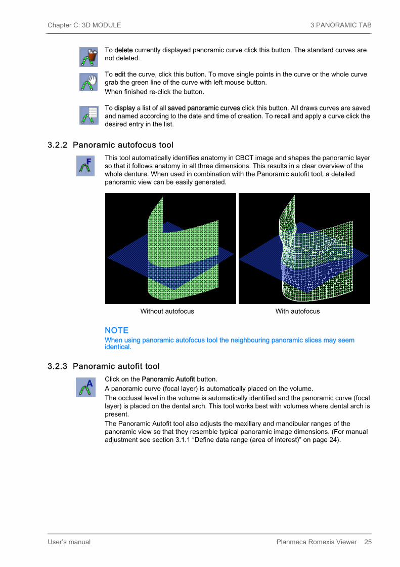
3.2.2 Panoramic autofocus tool This tool automatically identifies anatomy in CBCT image and shapes the panoramic layer so that it follows anatomy in all three dimensions. This results in a clear overview of the whole denture. When used in combination with the Panoramic autofit tool, a detailed panoramic view can be easily generated.
NOTEWhen using panoramic autofocus tool the neighbouring panoramic slices may seem identical.
3.2.3 Panoramic autofit toolClick on the Panoramic Autofit button.A panoramic curve (focal layer) is automatically placed on the volume. The occlusal level in the volume is automatically identified and the panoramic curve (focal layer) is placed on the dental arch. This tool works best with volumes where dental arch is present. The Panoramic Autofit tool also adjusts the maxillary and mandibular ranges of the panoramic view so that they resemble typical panoramic image dimensions. (For manual adjustment see section 3.1.1 “Define data range (area of interest)” on page 24).
Without autofocus With autofocus
User’s manual Planmeca Romexis Viewer 25

4 IMPLANT / CROSS SECTIONS TAB Chapter C: 3D MODULE
4 IMPLANT / CROSS SECTIONS TABIn the Implant / Cross Sections / cross sectional slices, axial slices and panoramic images can be created from the 3D data. The Cross Sections / Implant tab contains four views:
• Axial view (1)• Panoramic view (2)• Cross sectional slices view (3)• 3D rendered view (4)
The views can be expanded by clicking the small dual arrows in the ends of the view dividers or maximized by clicking the Maximize button.
26 Planmeca Romexis Viewer User’s manual

Chapter C: 3D MODULE 4 IMPLANT / CROSS SECTIONS TAB
4.1 Adjusting cross sectional slices
NOTEAdjustment in Cross sections view will also affect the settings in Panoramic view and vice versa and sagittal or axial rotation of the volume in the Panoramic view shows in the Cross sections view.
To mirror the cross sections click this button.
To mirror the cross-sections at the apex of the panoramic curve click this button.
To create two perpendicular slices of the implant or segmented tooth (instead of the normal cross sections view) click the Implant centric view button.
NOTEImplant centric view is available in Implants view only.
The slice on the left side is perpendicular to the panoramic curve (if defined) and the right side is parallel to the panoramic curve (if defined).
User’s manual Planmeca Romexis Viewer 27

4 IMPLANT / CROSS SECTIONS TAB Chapter C: 3D MODULE
To view the areas around the implant rotate the views with the slider. When moving an implant in any of the slices the implant centric view adjusts automatically to the new position.
To use implant centric view for another implant or segmented tooth added to the image click on the implant or tooth in 2D views or in the Object Browser.
To rotate the slices use the slider on top of them.
28 Planmeca Romexis Viewer User’s manual

Chapter C: 3D MODULE 4 IMPLANT / CROSS SECTIONS TAB
To adjust the spacing (1), width (2) and thickness (3) of the slices move the slider up or down. To define the number of slices move the mouse cursor over the slices to select the number of slices (4).
Using the cross sectional scroll barTo move the cross sections move the scroll bar to the right or left.
Moving the scroll bar shifts the visible slices along with the panoramic curve to the same direction. If the Cross section lines option is activated the visible slices will also shift to the axial and panoramic views. The middle section is indicated by a bright red line and ruler in the cross sections view.To move in cross sections voxel by voxel click on the arrows on both ends of the scroll bar.To move freely around cross sections drag the scroll cursor.To move in cross sections in increments of the distance between the slices, click between the scroll box and end arrows.
1 Spacing
2 Width
3 Thickness
4 Number of slices1
23
4
User’s manual Planmeca Romexis Viewer 29

4 IMPLANT / CROSS SECTIONS TAB Chapter C: 3D MODULE
4.2 Adjusting axial / panoramic slicesTo adjust axial / panoramic slices click this button in the upper right corner of the axial view.In the opening window the distance between the slices, the thickness and the number of slices can be defined.
4.3 Nerves
Draw nerveTo draw a new nerve channel click the Draw nerve button. Use the left mouse button to place points either on the panoramic or on the cross sectional view for a curve depicting the nerve channel of the patient. When finished click the right mouse button. The nerve channel will be displayed as a coloured line in the panoramic view and as dots of the same colour in the cross sectional views.
Nerve propertiesTo adjust the properties of a nerve channel click the adjustment button in the Object browser’s Nerves group.
The nerve can be named and the colour and diameter can be modified.
30 Planmeca Romexis Viewer User’s manual

Chapter C: 3D MODULE 4 IMPLANT / CROSS SECTIONS TAB
The Nerve properties dialogue can also be opened by double-clicking on the nerve in 2D slice views.
4.4 Implant tools
To place a pre-selected default implant into the plan click this button. The default implant can be defined in the Implant library.
To draw an approximation of the implant’s width and height, using the patient’s anatomy as a reference for sizing click this button.Next, search the nearest matching real implant from the Implant library.
To place an implant directly from the Implant Library click this button. Select the appropriate implant and press Add to add it into the plan.
Opens the implant verification tool, see section 4.4.1 "3D implant verification tool" on page 33.
To display the properties of a selected implant double-click the implant in the 2D slice views, or click this button in the Object Browser.
To set the length, diameter, and colour for the selected implant enter the appropriate value on the corresponding field or select the desired colour by clicking the colour map.
User’s manual Planmeca Romexis Viewer 31

4 IMPLANT / CROSS SECTIONS TAB Chapter C: 3D MODULE
To adjust the rotation angle of the selected implant drag the Rotation Angle slider.
32 Planmeca Romexis Viewer User’s manual
Chapter C: 3D MODULE 4 IMPLANT / CROSS SECTIONS TAB
4.4.1 3D implant verification tool
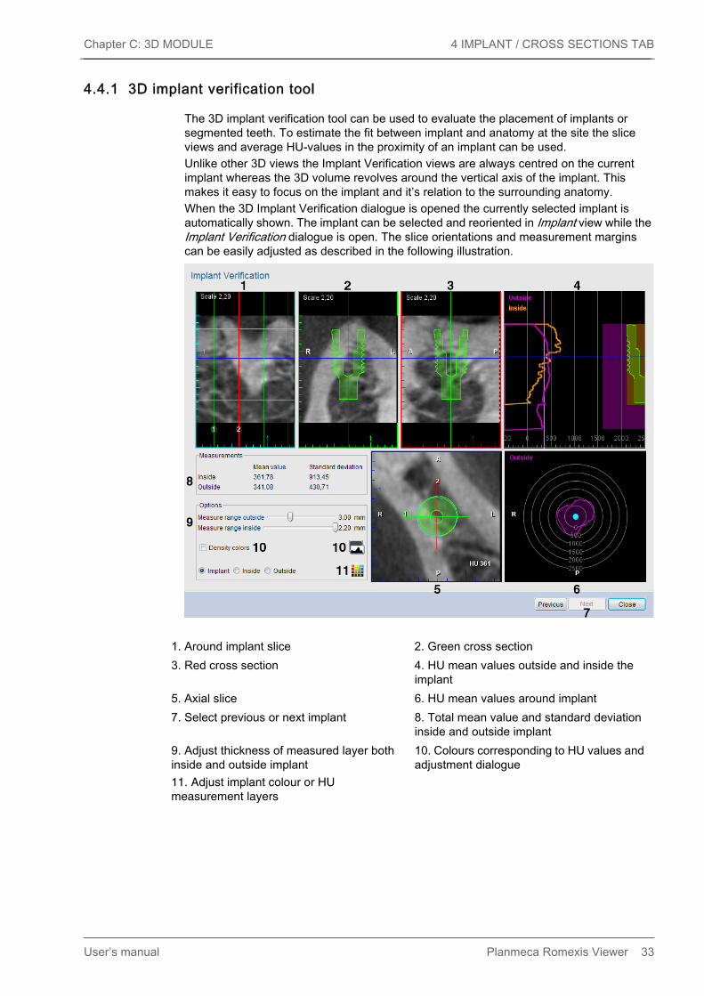
The 3D implant verification tool can be used to evaluate the placement of implants or segmented teeth. To estimate the fit between implant and anatomy at the site the slice views and average HU-values in the proximity of an implant can be used. Unlike other 3D views the Implant Verification views are always centred on the current implant whereas the 3D volume revolves around the vertical axis of the implant. This makes it easy to focus on the implant and it’s relation to the surrounding anatomy.When the 3D Implant Verification dialogue is opened the currently selected implant is automatically shown. The implant can be selected and reoriented in Implant view while the Implant Verification dialogue is open. The slice orientations and measurement margins can be easily adjusted as described in the following illustration.
1. Around implant slice 2. Green cross section3. Red cross section 4. HU mean values outside and inside the
implant5. Axial slice 6. HU mean values around implant7. Select previous or next implant 8. Total mean value and standard deviation
inside and outside implant9. Adjust thickness of measured layer both inside and outside implant
10. Colours corresponding to HU values and adjustment dialogue
11. Adjust implant colour or HU measurement layers
User’s manual Planmeca Romexis Viewer 33

4 IMPLANT / CROSS SECTIONS TAB Chapter C: 3D MODULE
Visual implant site evaluation
Axial, cross section and envelope slice viewsTo rotate the cross section views around the implant’s vertical axis by clicking and dragging with mouse in the axial slice. This allows you to inspect the anatomy by viewing the green and red cross sections (lines 1 and 2 respectively in the axial view) and compare them with the overview on the implant Envelope view.The implant envelope ring and the anatomical orientation of the data (anterior, posterior, left, right) are also shown on the Axial slice.To move the axial slice plane (blue line) up and down on the vertical axis of the implant use the mouse wheel. This allows you to view the axial slice at any level on the implant’s height.
Cross section viewsThe green and red cross sections (number 1. and 2. on the axial slice) are slices perpendicular to each other and parallel to the axis of the implant. They can be used to verify the anatomy around the implant when rotated using the axial view. The cross sections also show the silhouette of the implant, axial slice position and orientation (A, P, L, R).To zoom in and out use mouse wheel on the cross section and envelope slice views.
Implant envelope viewThe Implant Envelope view is a flattened cylinder view of the anatomy on the implant’s outer perimeter. It allows you to see if any of the implant’s outer wall would fall on a weaker bone for example instead of having to do with 360 degree rotation of the cross section views. Also the implant apex and insertion depths (cyan lines) and intersections with the green and red cross section slices are shown.
Density coloursTo enable pseudo-colouring of the data to differentiate different anatomy densities use this option. With pseudo-colours each gray scale value is mapped to different colour making the subtle differences between different values easier to perceive. The colours and their distribution over the gray scale histogram can be adjusted in the histogram.
Statistical implant site evaluationThe HU mean values display the mean value of voxels inside or outside of the implant in the margin. The margin is specified using the Options - Measure range outside / inside sliders. The values are shown in a line graph from top of the implant towards the apex with implant silhouette and margin thickness references on the right and HU value scale reference at the bottom.Under Measurements are shown the mean value totals corresponding to the vertical lines as well as the corresponding standard deviation values. By default the outside values are marked in violet and the inside values in orange. To adjust the colours use the colour chart icon at the bottom of the Options section.The bulls-eye chart at the bottom right indicates the distribution of mean HU values in the outside margin around the implant in the posterior/anterior and left/right directions.
34 Planmeca Romexis Viewer User’s manual

Chapter C: 3D MODULE 5 TMJ TAB
5 TMJ TAB
5.1 TMJ tools
5.1.1 Drawing PA line1. Verify alignment of the volume using the Axial view. Use the slider on its right edge to
bring condyles into view. 2. Draw right posterior anterior (PA) line using this button. 3. Click and hold down the left mouse button in the middle of the condyle.4. Draw the PA line by dragging with your mouse.
Planmeca Romexis will automatically display the opposite half of the line and round its total length to nearest millimetre.
5. Finish the line, by releasing the mouse button. The slices views will automatically appear.
6. To draw the left PA line click this button.7. Repeat the steps as described above starting from step 3. 8. Use the View settings dialogue to adjust the number, width and spacing of the PA and
lateral slices similar to other 3D modules. 9. To adjust the position of the PA lines verify that the Move / rotate volume button is
disabled. 10.Use the left mouse button to move a PA line or the right mouse button to rotate.11.To adjust the width of the slices (length of the PA line) either use the slice specific settings
menu or redraw the line.
User’s manual Planmeca Romexis Viewer 35

5 TMJ TAB Chapter C: 3D MODULE
Draw right PA line Use to draw and define the posterior-anterior PA line for the right side slices.
Draw left PA line Use to draw and define the posterior-anterior PA line for the left side slices.
Synchronise sides To enable / disable synchronisation of the left PA line with the right PA line click this button. When synchronisation is enabled (default) the length of the second PA line will be automatically constrained to match the length of the first drawn line. When synchronisation is disabled each PA line can be individually defined.
36 Planmeca Romexis Viewer User’s manual

Chapter C: 3D MODULE 6 3D MODULE TOP TOOLBAR
6 3D MODULE TOP TOOLBAR
6.1 Opening DICOM files
For detailed description see section 1 "OPENING DICOM FILES" on page 4.
6.2 Opening DICOMDIR filesFor detailed description see section2 "OPENING DICOMDIR FILES" on page 5.
6.3 Planmeca ProModelPlanmeca ProModel is a patient specific physical model to be used as an assisting tool for preoperative planning of dental and maxillo-facial procedures. It is designed to be used with the original 3D volume acquired with ProMax 3D. The model should not be used as the only tool for planning procedures. In no circumstances ProModel can be used in vivo. The Planmeca ProModel order button is enabled by default.
NOTEUser must have administrator rights in Planmeca Romexis to disable (or enable) Planmeca ProModel ordering, see section “LOCAL SETTINGS” in the Planmeca Romexis technical manual (10037884).
6.3.1 Placing order
NOTEPlanmeca ProModel is not autoclavable and it is not recommended to use liquid disinfectants.
NOTEIn case you need separate models for mandible and maxilla take 3D exposure with a mouthpiece on.
1. Open the volume of which you would like to create the model from the Explorer view.2. Click the ProModel button.
User’s manual Planmeca Romexis Viewer 37

6 3D MODULE TOP TOOLBAR Chapter C: 3D MODULE
The Planmeca ProModel order form opens.
3. Enter the necessary information.The obligatory fields are marked in bold. The order confirmation will be sent to the user by e-mail, please give a valid email address.
ProModel ID The ID will be printed on the ProModel. The software automatically uses the Person ID of the patient. The default ID automatically generated by Planmeca Romexis can be in text, number or special character format and can be freely modified.
Reference Used for order processing.The optional fields and buttons include:
Comments You can use the Comments field is for special requests, e.g. if you would like to order the model in other than the default (white) colour. If you would like to have the ROI marked in the model or give a notice to Planmeca concerning the volume you can write it down in the comments.
38 Planmeca Romexis Viewer User’s manual

Chapter C: 3D MODULE 6 3D MODULE TOP TOOLBAR
Reference Used for order processing.
Price listBy clicking this button a ProModel price list opens in your default web browser. If your computer is not online clicking the button gives the URL of the price list in your default web browser. The prices in the list are recommended prices. For further information contact your local Planmeca dealer.
Include nerves and implantsSelect this option if you have drawn mandibular nerve or placed implants in the patient’s data in Planmeca Romexis. The coloured nerve can be printed on the Planmeca ProModel and the implants will be included as cylinder representations.
NOTEFor the nerves to show in the ready ProModel, the order must be placed from the 3D module's Implant view.
Add billing addressIf you have selected the option Different Address for Delivery instead of Same address for Delivery and Billing this button will be enabled. To enter a different address for billing click the Add billing address button.
4. Enter the local Planmeca dealer information. It is required for billing purposes. The information is filled by your local Planmeca dealer and it needs to be entered once.
User’s manual Planmeca Romexis Viewer 39

6 3D MODULE TOP TOOLBAR Chapter C: 3D MODULE
• By selecting this box, I agree to these Terms and Conditions check boxTo read the terms and conditions click the respective hyper link. This box must be checked before placing the order.
Save this order form as a templateBy selecting this option you do not need to refill all the required fields every time you place an order.
5. After having entered all necessary information click the Continue button.6. Select the appropriate ordering option from the following:
NOTEIn all ordering options all personal information of the patient is removed from the 3D volume.
Send onlineThe image and order form are sent to Planmeca’s FTP server. The computer needs to be online and possible firewall needs to be set to allow outgoing FTP-connections. Order confirmation and courier package tracking number will be sent to customer’s email account
Burn to CD/DVDThe image and order are burned to CD or DVD which can be sent by mail to Planmeca.
Export to My DocumentsA zip-folder including the image and order form to user’s My Documents folder (OS WinXP).
7. Click Accept.
40 Planmeca Romexis Viewer User’s manual

Chapter C: 3D MODULE 6 3D MODULE TOP TOOLBAR
6.4 Save 2D viewThis tool can be used to generate 2D snapshots of 3D volumes. The snapshots will appear in the 2D module in CBCT group where they can be measured and processed using the tools described in the (see chapter C “2D MODULE”). By default the snapshots are generated as they appear on the screen but the appearance and number of snapshots can be adjusted in the Save 2D View window.
1. Click the Save 2D view on the top toolbar.
2. In the appearing window specify the image(s) or ranges of images to be included in the snapshots.
6.5 Virtual cephVirtual Cephalometric tool can be used to generate 2D cephalometric images from 3D volumes and save them to patient’s 2D images.
• To rotate and align the volume use left mouse button. Note that the projection is perspective free so the close and far anatomy can be aligned perfectly.
• To rotate the volume sagittally (nodding) use the Ctrl + right mouse button.
User’s manual Planmeca Romexis Viewer 41

6 3D MODULE TOP TOOLBAR Chapter C: 3D MODULE
• To adjust contrast and brightness use Ctrl + left mouse button.Use the direction buttons to set the direction of which the cephalometric image should be generated. These can be used together with crop options so that the far side of anatomy is removed from the cephalometric image creating an image where duplicate anatomy does not need to be considered. The following options can be selected from the drop-down menu:
• Default: Produces the most film like quality in the image. • Flat: Flattens the image by reducing differences in contrast between areas.• Log: Adds contrast
To show/hide ruler check/uncheck the Rulers check box.To turn on/off the ProFace profile overlay check/uncheck the ProFace profile check box.Use the scroll bar to adjust the left/right positioning of the ProFace profile line.
6.6 Save viewSaves the currently displayed view. Enter a name to the opening dialogue.
6.7 Reset view Restores the original orientation and settings of the views.
6.8 Image properties1. To view Image properties or add an image comment click the Image Properties button.
When finished click OK.
42 Planmeca Romexis Viewer User’s manual


Planmeca Oy | Asentajankatu 6 | 00880 Helsinki | Finland
tel. +358 20 7795 500 | fax +358 20 7795 555 | [email protected] | www.planmeca.com