ronald patterson lewis - internet archive
TRANSCRIPT

A DEVELOPMENTAL CW FM MULTI-TARGET RADAR
Ronald Patterson Lewis


3STGRADUATE SCHOOL
Monterey, California
THECJ
A DEVELOPMENTAL
CW FM MULTI-7TARGET RADAR
by
Ronald Patterson Lewis
Thesis Ad visor: David B. Ho Lsington
December 1971
Approved faon. pubtic n.cJl2jii> e; dii> V-JJoatioyi wnJiunltdd.


A Developmental
CW FM Multi-Target Radar
by
Ronald Patterson Lewis
Lieutenant, United States Navy
B.S.E.E., University of Florida, 1964
Submitted in partial fulfillment of the
requirements for the degree of
MASTER OF SCIENCE IN ELECTRICAL ENGINEERING
from the
NAVAL POSTGRADUATE SCHOOLDecember 19 71


ABSTRACT
The feasibility of an X-band (8.0-12.5 GHz) continuous-wave
multiple-target radar employing linear frequency modulation was
investigated.
From available laboratory equipment a working model was con-
structed and tested. Separate parabolic antennas were used for trans-
mitting and receiving. The transmitter employs a reflex klystron
followed by low and high-level traveling-wave tubes. The receiver
utilizes a single narrow-band crystal filter with a swept local oscillator
for range search.
Target data acquired with the developmental unit is presented.


TABLE OF CONTENTS
I. INTRODUCTION 7
II. GENERAL THEORY OF FM RADAR 9
A. PRINCIPLES OF OPERATION 9
1. Determination of Distance 9
2. Examination of the Spectrum 12
3. Considerations of Single-Gate FM
Radar Systems 13
B. COMPARISON BETWEEN PULSE AND FM RADAR 15
III. GENERAL ASPECTS OF FM RADAR APPARATUS 17
A. TRANSMITTING OSCILLATORS AND THEIR
MODULATION 17
B. ANTENNAS AND THE FEED-THROUGH PROBLEM 17
C. RECEIVING EQUIPMENT 18
IV. DEVELOPMENTAL FM RADAR 20
A. SYSTEM ANALYSIS 20
B. EXPERIMENTAL RESULTS 22
V. CONCLUSIONS 24
APPENDIX A EQUIPMENT LIST 25
APPENDIX B RADAR CHARACTERISTICS 26
FIGURES 27
BIBLIOGRAPHY 35

INITIAL DISTRIBUTION LIST 36
FORM DD 1473 37

LIST OF FIGURES
FIGURE PAGE
1. Linear FM Homodyne Radar 27
2. Method of Obtaining Echo Signals in FM Radar 27
3. Distribution of Range Beat Notes 28
4. Method of Resolving Range Ambiguity 28
5. Block Diagram of Developmental System 29
6. Sawtooth Generator Circuit 30
7. Map of NPGS 30
8. Map of Local Area 31
9. TWT Pulsed Off During Sawtooth Flyback 32
10. Transmit Spectrum Without Sawtooth Flyback
Suppressed 32
11. Transmit Spectrum With Sawtooth Flyback Suppressed 33
12. Radar Photograph at Long Range 33
13. Radar Photograph of the Sky 34
14. Radar Photograph at Short Range 34

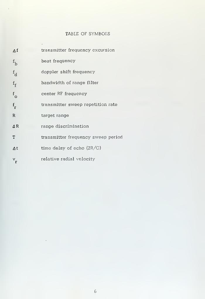
TABLE OF SYMBOLS
Af transmitter frequency excursion
f beat frequencyb
f . doppler shift frequencyd
f bandwidth of range filter
f center RF frequency
f transmitter sweep repetition rate
R target range
&R range discrimination
T transmitter frequency sweep period
At time delay of echo (2R/C)
v relative radial velocityr


I . INTRODUCTION
Continuous-wave frequency-modulated radar may be defined as
radar in which a continuous-wave transmission is frequency-modulated
in a known manner and correlated to the return signal in order to obtain
range information.
The earliest use of this type of system was by Appleton and
Barnett in 1924 [ 1] when they wished to obtain evidence of the exist-
ence of the ionosphere.
Since 1924, the principle of single-target frequency-modulated
radar has been used in aircraft altimeters . This type of altimeter came
into use during World War II [2, 3 J and is in widespread use today.
Little work was done on FM multi-target systems until 1940 when some
developments were made in England [4,5] and in the United States.
In 1955-1959 Keep [6] , Tucker [7 J , Kay [8] and others applied
the FM technique with better success. Still they concluded that a multi-
target system would have to await the development of such devices as
X-band amplifiers. In 1965 Barry and Fenwick of Stanford University
[9] demonstrated the improvement of a linear frequency-modulated pulse
ionogram over a pulsed sounder. Two advantages of CW FM are higher
average power for the same peak power and less vulnerability to narrow-
band interference.
Recent developments in solid-state technology have produced de-
vices and equipment that permit the construction of a practical


multi-target CW FM radar. The most obvious applications of this type
of system would be in situations where light weight, low power con-
sumption, and high reliability are of paramount importance. Light
weight requires operation at X-band or higher frequencies to obtain
narrow antenna beamwidth with reasonable antenna size.
Problems requiring further development include optimum solid
state circuitry for the complete system, and a duplexing system that
will permit the use of a single antenna.


II. GENERAL THEORY OF FM RADAR
A. PRINCIPLES OF OPERATION
A conventional pulse radar transmits a short pulse to obtain good
range resolution. In order to prevent range anbiguities , the pulse
repetition period must be at least equal to the delay of the signal from
the most distant detectable target. The above restriction results in
two shortcomings of the conventional pulse radar. First, since the
pulse width and pulse repetition frequency are constrained, the average
transmitted power can be increased only by increasing the peak trans-
mitted power.
The above-mentioned limitation of pulse radar can be overcome
by the use of CW radar. In the case of a CW radar, the average power
is equal to the peak power.
1 . Determination of Distance
Figure 1 illustrates a simplified block diagram of an FM
radar. Basically, energy taken from the transmitter is heterodyned with
the echo signal. The difference frequency is directly proportional to
distance. The relationship between the transmitted and received fre-
quency with linear FM is illustrated in Figure 2. Using linear sawtooth
modulation, the beat frequency is given by
dfb d t


where df/dt is the transmitter frequency excursion per transmitter fre-
quency sweep period (Af/T), t is the signal transit time (2R/C) and
C is the velocity of light. Substitution gives the range equation.
R = Cfb T
2 Af
In order to distinguish between targets at different ranges,
a set of frequency filters of bandwidth f with center frequencies equally
spaced may be used. Such a set of filters is used in what is known as
a multi-filter receiver.
As seen in Figure 3, for a single target illuminated for an
interval of time equal to or less than one sweep period, T, the spectrum
out of the mixer is continuous and is centered about f, . The spectrum
has a bandwidth between nulls of 2/(T- At). The range resolution will
be limited by the target spectral bandwidth if the filter bandwidth is
equal to or less than this amount, but will be limited by the filter band-
width if it is greater than this . With range resolution limited by spectral
bandwidth, the approximate equation for range resolution is given by
n ^ CT2 A f (T - A t)
If At << T, this becomes
CAR2 Af
This is equivalent to the range resolution of a pulse radar
having the same transmitter bandwidth. With a CW FM radar the range
10


resolution can be changed simply by changing £f without changing
anything else. In a pulse radar both the transmitted pulse width and
the IF bandwidth would have to be changed
.
During the flyback of the frequency modulation, false sig-
nals will be produced if the flyback time is finite. To avoid this in the
developmental system, the transmitter is suppressed during flyback.
Because the doppler frequency shift adds to or subtracts
from the beat frequency (depending on the relative motion of the target
and the sign of the slope of the frequency sweep), the indicated range
of a moving target will be inaccurate. The doppler frequency shift, f^
,
is given by
fd = -2 V
rfo
C
where v is the relative radial velocity and f is the center RF frequency,
For a relative velocity of 3 knots, the doppler shift at 9 GHz is approxi-
mately 900 Hz. It follows from the above equation and Figure 2 that
the range error due to target motion is
AR =Tv
r fo
It
For a 9 GHz radar with T - 380 microseconds and A f =
12 MHz, the range error is only 16 yards for a 100 knot relative radial
velocity. This is of little importance for a system that is designed pri-
marily for surface search, harbor and river navigation.
11


2 . Examination of the Spectrum
In a FM radar system with linear sawtooth modulation, the
transmitted wave is a CW signal of constant amplitude and linearly
changing frequency. Normally the transmit signal is considered repeti-
tive with repetition time T, and its Fourier transform consists of a
spectrum of lines evenly spaced at intervals of the repetition time.
However, with a free running oscillator where the phasing of the RF
is not coherent from sweep to sweep, the transmit signal is not repeti-
tive, and the transmit and receive spectrum is not a line spectrum but
rather a continuous spectrum.
Since the sawtooth modulating waveform does not have
instantaneous flyback, the transmit spectrum is as in Figure 10 and
the received signal out of the mixer consists of two beat notes (Figure 2,
3). This leads to a range ambiguity which is peculiar to FM systems.
However if the transmitter is pulsed off during the flyback time Figure
4a, 9) the transmit spectrum is as seen in Figure 11 and the second beat
note ambiguity vanished as illustrated in Figure 4b. With the type of
system mentioned, the received spectrum is continuous with a single
beat note (f^) for each point target and side lobes as seen in Figure 3.
Three other types of range ambiguity are present in a CW FM
system: second time around echoes, doppler frequency shift, and
finite bandwidth of the received beat note along with its side lobes.
The first of these can be minimized in the same way as with pulse radars
by making T large compared to the maximum expected echo time. The
12

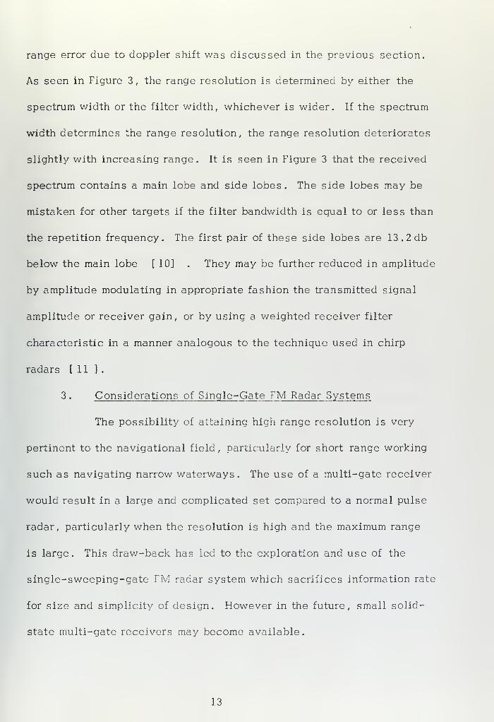
range error due to doppler shift was discussed in the previous section.
As seen in Figure 3, the range resolution is determined by either the
spectrum width or the filter width, whichever is wider. If the spectrum
width determines the range resolution, the range resolution deteriorates
slightly with increasing range. It is seen in Figure 3 that the received
spectrum contains a main lobe and side lobes . The side lobes may be
mistaken for other targets if the filter bandwidth is equal to or less than
the repetition frequency. The first pair of these side lobes are 13.2db
below the main lobe [10] . They may be further reduced in amplitude
by amplitude modulating in appropriate fashion the transmitted signal
amplitude or receiver gain, or by using a weighted receiver filter
characteristic in a manner analogous to the technique used in chirp
radars [ 11 ]
.
3 . Considerations of Single-Gate FM Radar Systems
The possibility of attaining high range resolution is very
pertinent to the navigational field, particularly for short range working
such as navigating narrow waterways. The use of a multi-gate receiver
would result in a large and complicated set compared to a normal pulse
radar, particularly when the resolution is high and the maximum range
is large. This draw-back has led to the exploration and use of the
single-sweeping-gate FM rsdar system which sacrifices information rate
for size and simplicity of design. However in the future, small solid-
state multi-gate receivers may become available.
13


In a single-gate system, the beat notes corresponding to the
various ranges are either scanned across a single fixed-frequency gate,
or the filter frequency is varied. Since range is now being scanned it
is obvious that the overall data rate must decrease or the sensitivity
be lowered. Once range resolution has been determined, the range-
frequency scanning rate, dfjyMt, should be about the same as the square
of range filter bandwidth (ff) . For maximum sensitivity, the range
filter bandwidth ratio should be matched to the modulation repetition
rate. To increase the data rate the modulation repetition rate can be
increased and the bandwidth of the receiver filter increased.
Increase in the modulation repetition rate is limited by the
occurrence of second-trace echoes and is therefore mainly applicable to
short range scales. Use of a receiver bandwidth larger than the optimum
is undesirable since range resolution would be impaired. For example,
with(At«T), ff= 1/T and Af = 12 MHz
Q^ R ~ 2~aT
= 14 yds *
If the filter size is doubled, then range resolution is limited by filter
bandwidth, and is given by
CffTAR
2 Af
The range resolution deteriorates to 28 yards, twice as much
as with the narrower filter.
14


B. COMPARISON BETWEEN PULSE AND FM RADARS
It can be shown theoretically that an FM radar with a multi-gate
receiver is equivalent in performance to a pulse radar having the same
average power and utilizing the same bandwidth, antenna beamwidths
,
scanning speeds, operating frequency, receiver noise figure and other
performance factors [ 12 ] .
However some important differences in implementation are apparent
between pulse and FM radar techniques . FM radar transmits CW power
and is therefore not concerned with high peak powers . This difference
becomes extremely important when the equivalent pulse set has peak
powers approaching, or greater than that which the waveguide system
can tolerate without breakdown. In pulse radar a duplexer provides
isolation between transmitter and receiver to prevent receiver burn out
or excess receiver dead time following the transmitted pulse. In CW
FM radar, isolation is required to prevent transmitter noise from reducing
sensitivity and to prevent receiver saturation. Isolation can be achieved
by use of two antennas or any suitable duplexing method L 13 1 .
In FM radar the wide bandwidth necessary to attain the desired
range resolution is only required at RF frequencies while in pulse radar
wide bandwidth is also required in the IF amplifier. This sets a practical
limit to the range resolution attainable with pulse techniques. However
it should be noted that to take advantage of the higher range resolutions
possible with the FM technique, a high degree of modulation linearity
is required [10] . If the FM system uses a bank of parallel filters in
15


the receiver, the number required would have to be equal to the total
number of range intervals to be resolved. Special display techniques
are required if a display of the conventional type is desired. A range
display can be obtained from the single filter FM system simply by
effectively sweeping the filter across the received spectrum as has been
discussed. This convenience arises as a result of the linear-frequency
sweep. A fixed time delay At = 2R/C corresponds to a fixed difference
frequency, f]-,, where
rdf. ..
fb- dtAt
The spectrum (amplitude-frequency) of the received signal out of the
mixer thus becomes the normal A-scope (amplitude-range) display.
Finally, the relative immunity to narrow-band interference that frequency
modulation systems enjoy over amplitude modulated systems is retained.
16


III. GENERAL ASPECTS OF FM RADAR APPARATUS
A. TRANSMITTING OSCILLATORS AND THEIR MODULATION
At frequencies higher than about 3 GHz, reflex klystrons are a
convenient signal source. The frequency of oscillation of the klystron
oscillator is determined by the resonant frequency of the cavity and the
magnitude of the repeller voltage. By simply changing the repeller
voltage the frequency can be modulated over the range required for a
CW FM radar. However one drawback is its relatively low efficiency.
Indications are that in the very near future cheaper solid-state
sources will be available with adequate power and higher efficiency to
replace the klystron.
In all FM oscillators frequency modulation is always combined
with some incidental amplitude modulation which may be excessive when
wide-frequency deviations are required. With the frequency deviations
needed for FM radar, amplitude modulation is not a problem.
B. ANTENNAS AND THE FEED-THROUGH PROBLEM
Due to noise in the transmitter of an FM radar, it may be difficult
to detect weak target echoes if a single antenna is used for both trans-
mission and reception. Two separate antennas are more practical, and
precautions should be taken to prevent transmitted energy from passing
directly from the transmitting to the receiving antennas .
17


The coupling or leakage between the transmitting and receiving
antennas gives the same result as a stationary target at essentially
zero range. Strong coupling may produce receiver overloading and hence
mask weak target signals.
For X-band, high directivity can be obtained with moderate apera-
ture size. Good isolation between two antennas is relatively easy to
obtain when their directivity is high, and very little shielding between
antennas is necessary.
C. RECEIVING EQUIPMENT
In the design of any radar receiver, special care should be taken
to suppress noise which may be developed at its input and which has a
frequency spectrum falling within the amplification response of the
receiver. The main source of this noise in the CW FM receiver is the
FM noise associated with the transmitter and the local oscillator.
The difference frequency in the FM radar is obtained by mixing
the received signal with a local signal obtained directly from the trans-
mitter. Undesirable amplitude modulation may accompany the frequency-
modulation process. Possible sources of this amplitude modulation
include non-uniform frequency response in the input tank circuit of the
mixer (Figure 5), in the transmitter output, and in the frequency trans-
lation system of the superheterodyne receiver.
The resulting amplitude modulation is periodic at the modulation
rate and may or may not be sinusoidal in nature.

In the developmental system this type of interference is present,
However, with a little care in alignment and adjustment its amplitude
can be made negligible.
19


IV. DEVELOPMENTAL FM RADAR
A. SYSTEM ANALYSIS
The system as illustrated in Figure 5 employs an RF signal
generator linearly frequency modulated by a sawtooth waveform (Figure 8).
The RF frequency is centered at 9 GHz with a total frequency deviation
of 12 MHz. This spectrum is then mixed with a 30 MHz signal and
passed through an upper side-band filter. The result is a spectrum
centered about 9.03 GHz with 12 MHz frequency deviation. This signal
is amplified by low and high-level broad-band traveling-wave tubes.
The high level TWT is pulsed on and off in synchronism with the modu-
lating sawtooth as shown in Figure 9 to eliminate spurious signals
associated with the frequency retrace. Two circular parabolic antennas
with 3 degree beamwidths are used for transmitting and receiving.
In order to determine range, a portion of the output from the signal
generator is fed through a band-pass filter and introduced into the
receiver mixer. The signal introduced into the mixer is thereby offset
30 MHz with respect to the transmitted signal. Since the antennas are
physically located one above the other and there is some leakage between
them, a 30 MHz signal representing zero range appears at the output of
the IF preamplifier. Because of the positive slope of the modulation
sawtooth applied to the repeller of the reflex klystron, the output of the
RF generator sweeps down in frequency. This results in the received
signal being higher in frequency at any instant than the transmitted
20


signal. Therefore the received signal out of the mixer is nominally
30 MHz plus the frequency difference (f^) resulting from the range delay
for each target in the antenna beam. Thus the IF signal for zero range
is a nominal 30 MHz, while the signal frequency associated with other
targets increases in direct proportion to range. If the frequency of the
IF signal generator is slowly decreased from 30 MHz, this total target
spectrum is translated down in frequency so that first the zero-range
signal appears in the passband of the 30 MHz crystal filter, and then
in succession signals associated with targets at greater ranges.
The output of the 3 . 8 KHz wide crystal filter is amplified, detected,
and applied to the vertical plates of an oscilloscope. It could also be
used for intensity modulation of a planned position indicator (PPI)
oscilloscope. Horizontal deflection of the oscilloscope is from the
same low-frequency sawtooth generator which produces the slow frequency
translation of the IF signal generator. The result is an "A" scope
presentation.
A high-frequency radio receiver was used to amplify and detect
the output of the crystal filter. Unfortunately, the only receivers avail-
able had automatic gain control (AGC) time constants that were too slow
for the desired range sweep rates. The result of using a long AGC time
constant is that an averaging process is inevitable and target definition
is lost. Since a fully satisfactory receiver was not available, and time
did not permit the development of a suitable receiver, most observations
21


of targets were made by examining the spectrum with a spectrum analyzer
tuned to 30 MHz. This gave a very satisfactory "A" scope type of
presentation.
B. EXPERIMENTAL RESULTS
Because of the narrow beamwidths of the two parabolic antennas
and the fact that they must be trained independently in azimuth and
elevation, it was very difficult to align them on a target. The two
pencil beams must coincide for maximum target illumination. Microwave
filter alignment and proper phasing of the blanking signal with respect
to the transmitter frequency sweep is critical for proper system operation
and range calibration. Drift of the signal generator frequency which was
believed to be caused by line voltage fluctuations, was also a problem.
Even with these difficulties and the limited field of view from the radar
location in Spanagel Hall room 704, some very meaningful results illus-
trating the system's capabilities were obtained.
Examination of Figure 8 and Figure 12 demonstrates excellent
correlation between the "A" trace presentation and the physical picture.
The vertical alignment is such that the main portion of the beam is
trained on Point Alones . If the beam is lowered, the echo from the
Coast Guard Pier becomes much larger in amplitude. Sea clutter is
obvious after the beach houses and after the boats and the Coast Guard
Pier. This sea clutter disappears in the shadow beyond Point Cabrillo,
and only thermal noise is obtained in this region. Figure 13 also shows
22


largely thermal noise since the antennas were directed to the sky. As
can be seen from the amplitude of the zero-range leakage signal, the
receiver gain has been greatly increased.
Figure 7 and Figure 14 illustrate a short-range capability.
Ingersoll Hall is two stories higher than Halligan Hall and with the
antennas trained on the former, it shows a larger return in spite of its
greater range. The large return just after the initial Halligan Hall return
is the windowed structure in the center of the building roof. The large
target just after the initial Ingersoll Hall return is from a railing on the
roof at the far side of the building.
23


•
V. CONCLUSIONS
It has been demonstrated that it is feasible to build a multi-target
CW FM radar.
With state-of-the-art solid-state technology, many improvements
are possible. These improvements include a solid-state linear FM
oscillator to replace the reflex klystron traveling-wave-tube combination,
an offset local oscillator that is phase-locked to the sum or difference
of the transmitter and IF frequencies, and a solid-state IF amplifier with
a fast time constant to react to narrow targets
.
Range side lobes were not observed in the photographs. This is
largely because the frequency analyzer utilizes Gaussian filters.
Another method of reducing range side lobes is shown dotted in Figure 5.
This addition of a balanced modulator fed by a pulse-forming network in
phase with the transmitter frequency sweep would cosine modulate the
receiver gain. This technique reduces the amplitude of the side bands
accompanying the echo spectrum associated with each target at the IF
frequency (Figure 3), and hence reduces the amplitude of the range side
lobes f 10 ] .
24


APPENDIX A
EQUIPMENT LIST (FIGURE 5)
Synthesizer Driver, Hewlett Packard , 5110B.
Frequency Synthesizer, Hewlett Packard, 5105A.
Spectrum Analyzer, Tektronix Inc. , 491.
Oscilloscope, Tektronix, Inc., 546.
Wide Band (DC-500KC 50 Watt) Amplifier, Krohn-Hite (Used to amplify
modulation pulse for HP495A TWT).
HF VCG Generator, Wavetek, 142.
R-390A/URR IF Receiver, Copehart Corp.
Regulated Power Supply, Power/Mate Corp.
Pulse Generator, Data Pulse, 101.
RF Signal Generator (7.0-11.0 GHz), Polarod , 1108M4.
Low Level Broad Band Traveling Wave Tube, Varian.
Microwave Amplifier (7.0-12.4 GHz), Hewlett Packard, 495A.
Filter (8580-9600 MHz) , Frequency Engineering Laboratory, 850CW.
Balanced Modulator (0 . 2-500 MHz) , RELCOM, Ml.
Uniline Isolator, Lewis and Kaufman Electronics Corp.
DA-138/TRM-3 Crystal Detector.
X-Band Airborne Parabolic Reflectors, 20-inch for transmit, 18-inch
for receive.
Crystal Mixer (8 . 5-9 . 6 KMHz) and 30 MHz Preamplifier, Varian, XBH-7
Crystal Mixer, Serial No. 1-2-101, USNPGS.
Crystal IF Filter, Damon, 6647A.
25


APPENDIX B
RADAR CHARACTERISTICS
TRANSMITTER:
POWER OUT 2 Watts Maximum
FREQUENCY DEVIATION 12 MHz Maximum
SWEEP PERIOD 380 Microseconds
SWEEP RETRACE TIME (TRANSMITTER OFF) 20 Microseconds
CARRIER FREQUENCY 9.00 GHz
RECEIVER:
RECEIVER NOISE FIGURE
IF BANDWIDTH
SHAPE FACTOR
IF CENTER FREQUENCY
13.8db
3. 8 KHz (3db)
60/6 = 3.7:1
30,000,015 Hz
ANTENNA CHARACTERISTICS:
RECEIVER
TRANSMITTER
18 inch circular
parabolic reflector,
approximately
3 degree beamwidth
20 inch parabolic
reflector, approxi-
mately 3 degree
beamwidth.
26


FMMODULATOR
fo ±Af-£*** XMTR
RNGFILTERS
Figure 1
.
Linear FM homodyne radar.
TRANSMITTED
ECHO
[-*- 1=1/%
c
TIME
TIME
Figure 2
.
Method of obtaining echo signals in FM radar,
(a) Frequency variation of signals.
(b) Beat frequency of one target.
27


LOWER BEAT NOTE
UPPER BEAT NOTE
2/At
FREQUENCY
Figure 3
.
Distribution of range beat notes
TRANSMITTER ON OFF-
TIME
<wCQ
ow!=>
Gr~
Uh
T (b) TIME
Figure 4
.
Method of resolving range ambiguity.
(a) Transmit signal pulsed off during flyback
(b) Beat frequency of single target.
28


eQ) j+-> <w ,
fc-HW rQ
-I Cro CD
t; a£ ag <
. a $-O <D
r-< U)
(1) ^ ^(-. > Cnp (11 c—
i
of
d<listi
H SS gra a-iH -^-D 3* s*Oo ^—i oCQ Pi-
29


+ 18VO
< 12K
S 1
330 <>
> IK
<>
i 22K
2N491 r-"°-luf
,*
0.0!
+ vVNA-/25K
2N167
2K
^—
O
AAA
Figure 6
.
Sawtooth generator
BEAM WIDTH
INGERSOLL '^-'r '»
HALUGAN
av
343 YDS
ROOT 305YDSI 1
TBULLARD
rH—
I
i
173^
J '133YDS
RADAR £>£> t L
SPANAGEL HALL
Figure 7
.
Map of NPGS
30


PACIFIC GROVE
STACK
MONTEREY
3° BEAMWIDTH
POINT CABRILLO
4000 YDSPOINT ALONES
KMBY TOWER LJL PACIFICOCEAN
3000 YDS
2500 YDS
v COAST GUARD PIER
J .MONTEREY WHARF
HOUSES 1000 YDS
NPGS
SPANAGEL HALL
Figure 8
Map of local area
31


Figure 9
.
TWT pulsed off during sawtooth flyback.
Horizontal: 100 microseconds per division,
Figure 10.
Transmit spectrum without sawtooth flyback suppressed
Horizontal: 2 MHz per division.
32


Figure 11.
Transmit spectrum with sawtooth flyback suppressed
Horizontal: 2 MHz per division.
Figure 12
.
Radar photograph at long range
520 yards per division.
33


Figure 13
.
Radar photograph of the sky,
Figure 14.
Radar photograph at short range52 yards per division.
34


BIBLIOGRAPHY
1. Appleton, E. V. and Barnett, M. A. F. , "On Some Direct Evidencefor Downward Atmospheric Reflection of Electric Rays ,
"
Proceedings of the Royal Society , p. 554, 1926.
2. Luck, D. G. C. , F.M. Radar , McGraw-Hill Book Company, Inc. ,
New York, 1949.
3. Smith, R. A. , Radio Aids to Navigation, Cambridge UniversityPress, 1947.
4. Standard Telephones and Cables Ltd, British Patent 581169.
5. Rust, N. M. and Partington, G. E., British Patent 621846.
6. Keep, D. N. , "Frequency-Modulation Radar for Use in the
Mercantile Marine." Proceedings I.E.E . Paper No. 9 4 OR,
p. 519, November 1955.
7. Tucker, D. G. , "Underwater Echo-Ranging," Journal of the British
Institution of Radio Engineers , p. 243, 1956.
8. Kay, L. , "A Comparison between Pulse and Frequency ModulationEcho-Ranging Systems," Journal of the British Institution of
Radio Engineers , 1. 105, 1959.
9. Barry, G. H. and Fenwick, R. B. , "Extraterrestrial and Ionospheric
Sounding with Synthesized Frequency Sweeps," Session No. 7
WESCON/65 , p. 8-12.
10. Hymans and Lait, "Analysis of a Frequency-Modulated Continuous-
Wave Ranging System," Proceedings I.E.E . , Paper No. 3264E,
p. 368, July 1960.
11. Skolnik, M. I., Introduction to Radar Systems , McGraw-Hill Book
Company, Inc. , New York, 1962.
12. Gnanalignam, S. , "An Apparatus for the Detection of WeakIonospheric Echoes," Proceedings I.E.E. , Paper No. 1670,
p. 243, July 1954.
13. Ramsay, J. F. , "Circular Polarization for C.W. Radar," Proceedings
of a Conference on Centrimetric Aerials for Marine Navigational
Radar , Ministry of Transport, 1952.
35


INITIAL DISTRIBUTION LIST
No. Copies
1. Defense Documentation Center 2
Cameron Station
Alexandria, Virginia 22314
2. Library, Code 0212 2
Naval Postgraduate SchoolMonterey, California 93940
3. Professor David B. Hoisington, Code 52Ha 1
Department of Electrical Engineering
Naval Postgraduate School
Monterey, California 93940
4. LT Ronald P. Lewis, USN 1
USS HANCOCK (CVA-19)
FPO San Francisco 96601
36


Security Classification ^_
^
^.————————
—
————
—
DOCUMENT CONTROL DATA - R & D
.Security classification of tltla. body of abstract and indexing annotation n.».si be .nfered when tf,. 0V« r' f/
_reP0,<" ^""'"'^
ORIGIN* ting ACTIVITY f Corporate aul/iorj
Naval Postgraduate School
Monterey, California 93940
2«. REPORT SECURITY CLASSIFICATION
Unclassified26. CROUP
REPORT TITLE
A Developmental CW FM Multi-Target Radar
DESCRIPTIVE NOTES (Type of report and.inclusive dales)
' Ma ster's Thesis; December 1971
"authORiSI (First name, middle initial, last name)
Ronald Patterson Lewis
. REPOR T D A TE
December 1971CONTRACT OR GRANT NO.
b. PROJEC T NO.
7a. TOTAL NO. OF PAGES
38176.
NO. OF REFS
13
9a. ORIGINATOR'S REPORT NUMBER(S>
96. OTHER REPORT uOISi (Any other numbers that may be aaslgned
this report)
DISTRIBUTION STATEMENT
Approved for public release; distribution unlimited
II. SUPPLEMENTARY NOTES 12. SPONSORING MILITARY ACTIVITY
Naval Postgraduate School
Monterey, California 9 3940
13. ABSTRACT
The feasibility of an X-band (8.0-12.5 GHz) continuous-wave multiple-target
radar employing linear frequency modulation was investigated.
From available laboratory equipment a working model was constructedI
and
tested Separate parabolic antennas were used for transmitting and rece ving
.
The transmitter employs a reflex klystron followed by low »d high-level
traveling-wave tubes . The receiver utilizes a single narrow-band crystal filter
with a swept local oscillator for range search.
Target data acqu ired with the developmental unit is presented.
DD,Tv".,1473,PAGE "
S/N 01 01 -607-681 1
37 Security Classification A- 31406


Security Classification
KEY WORD!
Radar
Frequency-Modulation
Continuous-Wave
3 ,
F
r.".,1473 < BACK)
0101 -807-682138 Security Classification lk - 3 1 4 01


\

f
ThesL614c.l
is
Lewi s
A deveFM multi
133895
lopmental CW-target radar
I 6 o C t *ra24 JUL 74
o 1 m n O218*4
- -.^ 2 U U
ThesisL614c.l
133895Lewis
A developmental CW
FM multi-target radar.

£3 2768 00103118DUDLEY KNOX LIBRARY
W