roof power kit - polaris inc
TRANSCRIPT
APPLICATIONVerify accessory fitment at Polaris.com.
BEFORE YOU BEGINRead these instructions and check to be sure all parts and tools are accounted for.Please retain these installation instructions for future reference and parts orderinginformation.
KIT CONTENTSThis kit contains parts for installation of the Roof Power Kit only. Prior installation of one of the followingadditional kits is also required (sold separately):• Premium Roof Kit, PN 2882912 or 2882913• Poly Roof Kit, PN 2882911• Other compatible roof kit
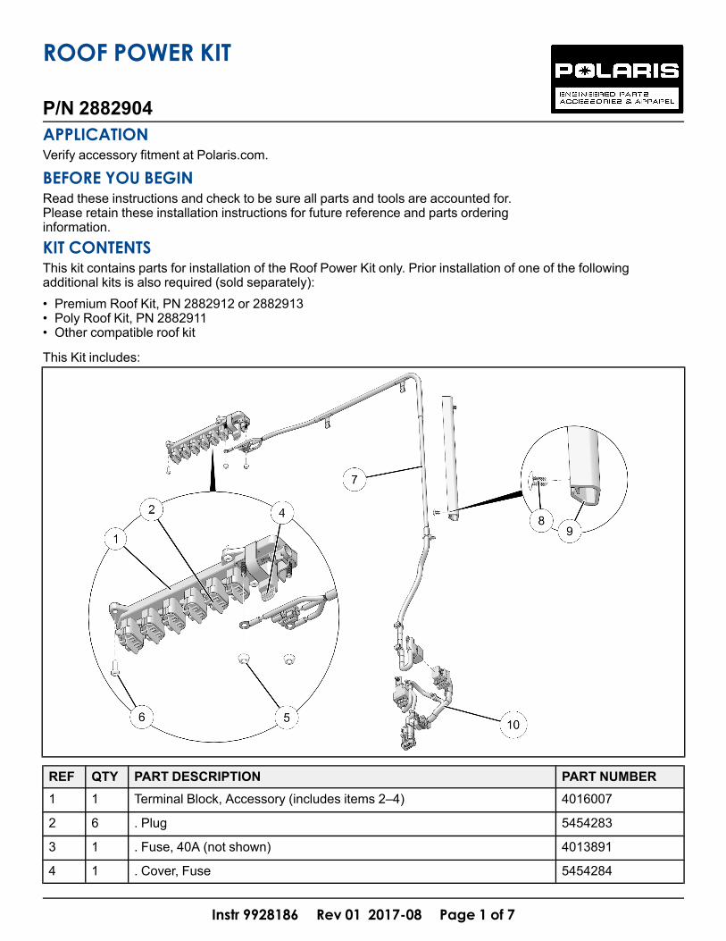
This Kit includes:
REF QTY PART DESCRIPTION PART NUMBER1 1 Terminal Block, Accessory (includes items 2–4) 4016007
2 6 . Plug 5454283
3 1 . Fuse, 40A (not shown) 4013891
4 1 . Cover, Fuse 5454284
Instr 9928186 Rev 01 2017-08 Page 1 of 7
P/N 2882904
ROOF POWER KIT

Instr 9928186 Rev 01 2017-08 Page 2 of 7
REF QTY PART DESCRIPTION PART NUMBER5 2 Nut, Hex Flange, Serrated - M6 7547270
6 4 Screw, Torx® Pan Head, High/Low - #14 X 3/4 7519731
7 1 Harness, ROPS 2414243
8 2 Push Dart 76700889 1 Conduit, Routing 5416632
10 1 Harness, Rear Firewall 2414073
1 Instructions 9928186
TOOLS REQUIRED
• Safety Glasses• Cutting Tool• Deburring Tool• Drill• Drill Bit: 1/4 inch (6 mm)
• Push Dart (Panel Clip) Tool*• Screwdriver Set, Phillips*• Screwdriver Set, Torx®• Socket Set, Metric• Wrench Set, Metric
* Tool requirement dependent on specific installation.
IMPORTANTYour Roof Power Kit is exclusively designed for your vehicle. Please read the installation instructions thoroughlybefore beginning. Installation is easier if the vehicle is clean and free of debris. For your safety, and to ensure asatisfactory installation, perform all installation steps correctly in the sequence shown.
ASSEMBLY TIMEApproximately 35 minutes
NOTEAdditional time may be required for optional steps, or
to accommodate other accessories.
HARNESS DETAILROPS HARNESSuu:
Instr 9928186 Rev 01 2017-08 Page 3 of 7
REF PART DESCRIPTION WIRECOLOR
PIN QTY/GENDER
CONNECTS TO
7A Ring Terminal, 1/4 inch (6 mm) ID (withboot)
Red - Accessory terminal blockq, studBAT +
7B Connector, Key Ignition - 1 female Accessory terminal blockq,connector ACC
7C Ring Terminal, 1/4 inch (6 mm) ID Black - Accessory terminal blockq, studBAT -
7D Clip, Edge (Spring) - - Vehicle structure
7E Clip, Routing - - Vehicle structure
7F Clip, Edge - - Vehicle structure
7G Connector, Chassis Cab Bulkhead, 90degree
- 10 male Rear firewall harnessa, connector10A
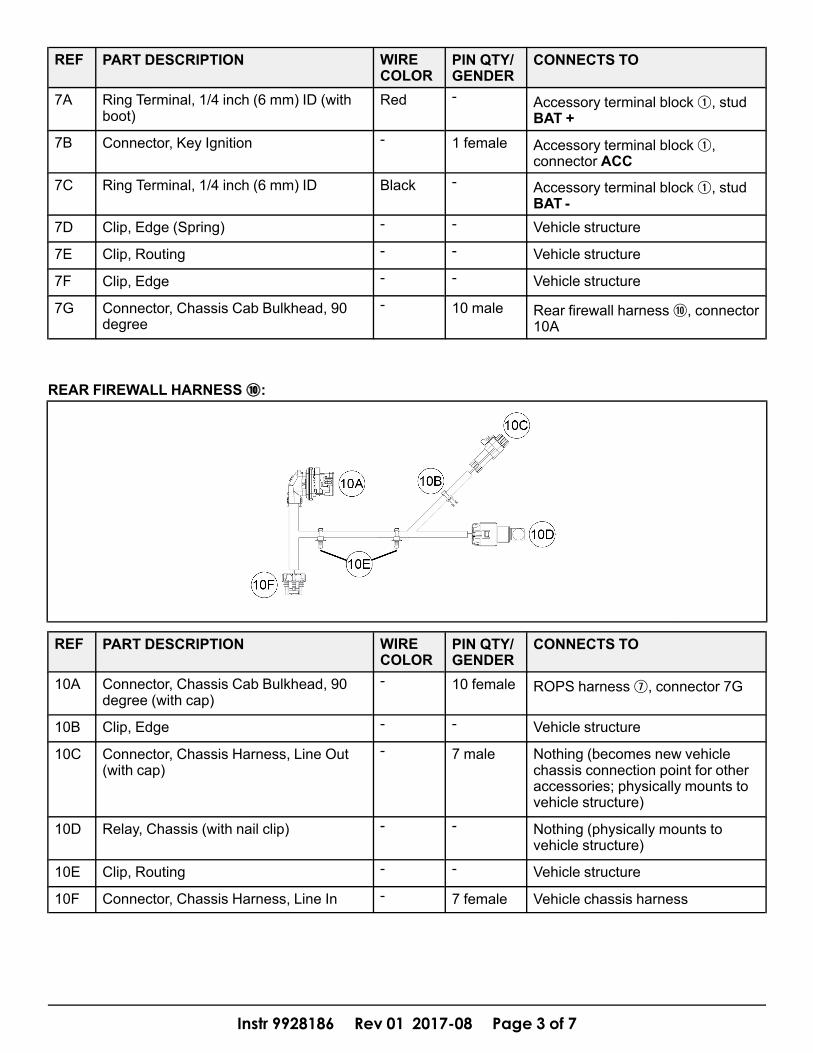
REAR FIREWALL HARNESSaa:
REF PART DESCRIPTION WIRECOLOR
PIN QTY/GENDER
CONNECTS TO
10A Connector, Chassis Cab Bulkhead, 90degree (with cap)
- 10 female ROPS harnessu, connector 7G
10B Clip, Edge - - Vehicle structure
10C Connector, Chassis Harness, Line Out(with cap)
- 7 male Nothing (becomes new vehiclechassis connection point for otheraccessories; physically mounts tovehicle structure)
10D Relay, Chassis (with nail clip) - - Nothing (physically mounts tovehicle structure)
10E Clip, Routing - - Vehicle structure
10F Connector, Chassis Harness, Line In - 7 female Vehicle chassis harness

Instr 9928186 Rev 01 2017-08 Page 4 of 7
INSTALLATION INSTRUCTIONS1. Shift vehicle transmission into “PARK”. Turn key to
“OFF” position and remove from vehicle.2. Flip up passenger seat bottom, remove driver’s
seat and underseat storage compartment, thendisconnect black negative (-) cable from battery.
3. Gain access.a. Raise vehicle bed.b. Remove rear roof liner (if installed).
NOTEFront roof liner can remain installed.
i. Remove rear (roof mounted) speakers, ifinstalled.
ii. Remove seven push dartsA, two from rearedge and five from front edge. Retain pushdarts.
iii. If overhead light is installed against liner,remove it. Otherwise, remove two eachscrewsB and washersC. Retainhardware.
iv. Carefully pull LH and RH edges of linerfrom between ROPS and roof seal, thenremove rear edge of liner from roof supportchannelD.
4. Install terminal blockq to roof using four screwsy. Ensure terminal block is oriented with threadedbattery studs on LH side of roof as shown. Do notover-tighten screws.
5. Carefully open conduito to expose fastenerholes, then push two dartsi through holes. DoNOT install conduit to B-pillar until next step.
6. Clean B-pillar surface as required to ensure propertape adhesion. Peel adhesive backing fromconduito, push dartsi into corresponding B-pillar holes, then press conduit firmly into place.

Instr 9928186 Rev 01 2017-08 Page 5 of 7
7. Install rear firewall harnessa.
NOTESee previous section, HARNESS DETAIL, for
connector identification.
a. Carefully cut openingE in rear close-off panelto allow installation of harness connector 10A.Debur edges of opening as required.
b. Remove locking clipF from connector 10A bysliding clip upward. Retain clip.
c. Remove protective capG from connector 10A.d. Remove protective cap from existing chassis
harness connectorH, then join to matingconnector 10F.
e. Temporarily insert connector 10A into newly cutopening. It is not necessary to reinstall lockingclipF at this time.
f. Hold connector 10C and chassis relay 10D infinal positions, then mark and drill three 1/4inch (6 mm) holes in rear close-off panel:• Two holes for routing clips 10E• One hole for nail clipF (on top of relay 10D)
IMPORTANTControl drill depth to prevent damage to underlying
structure or components.
NOTESpecific hole location is not critical as long as
chassis relay 10D fits into recessed cavity in panel.
g. Secure rear firewall harnessa to rear close-offpanel using two routing clips 10E, nail clipF,and edge clip 10B.

Instr 9928186 Rev 01 2017-08 Page 6 of 7
h. Re-insert connector 10A into opening (ifremoved during drilling), then reinstall lockingclipF to secure connector to close-off panel.If locking clip binds in mating connector slot,ensure connector is fully inserted into openingso locking clip can be installed straight down.
NOTESeatbelt retractor and associated mounting bracket
shown transparent for clarity.
8. Install ROPS harnessu.a. Join connector 7G on ROPS harnessu to
connector 10A on rear firewall harnessa.
b. Route opposite end of ROPS harnessubehind seatbelt retractor mounting bracketupwards toward roof, then secure to bracketusing two edge clips 7F.
c. Insert ROPS harnessu into routing conduito,then secure harness to ROPS B-pillar (at lowerend of conduit) using routing clip 7E.
d. Join connector 7B to mating connectoridentified as ACC on terminal blockq.
e. Install ring terminals to terminal blockq usingnutst as follows:i. Ring terminal 7A (RED wire/heat shrink
tubing) to post identified as BAT +; installboot over post
ii. Ring terminal 7C (BLACK wire/heat shrinktubing) to post identified as BAT -
f. Secure ROPS harnessu to ROPS roofsupport using two edge clips 7D.

Instr 9928186 Rev 01 2017-08 Page 7 of 7
9. Restore access.10.Reconnect black negative (-) cable to battery, then
reinstall under-seat storage compartment anddriver’s seat.
FEEDBACK FORMA feedback form has been created for the installer to provide any comments, questionsor concerns about the installation instructions. The form is viewable on mobile devicesby scanning the QR code or by clicking HERE if viewing on a PC.
FEEDBACK FORM