roofer: an engineered management system …navfacengcom), u.s. naval base, philadelphia, pa, under...
TRANSCRIPT

USACERL TECHNICAL REPORT M-90/04December 1989
Roofing Maintenance Management SystemUS Army Corpsof Engineers F COPYConstruction EngineeringResearch Laboratory
AD-A218 529
ROOFER: An Engineered Management System(EMS) for Bituminous Built-Up Roofs
byDavid M. BaileyL)onald E. BrothersonWayne TobiassonAl Knehans
This report gives instructions for using ROOFER,an engineered management system for bitumi-nous built-up roofs that is designed to helpmilitary installations make the best use of roofmaintenance and repair (M&R) funds.
This system includes procedures for dividingroofs into manageable sections; collecting andmaintaining inve tory information; surveying,rating, and evaluating roof condition; and deter-mining general M&R needs and priorities.
The overall roof condition rating procedure is D T ICbased on the Roof Condition Index, which iscomposed of separate condition indexes for the ELECTEmembrane, flashing, and insulation. 3t FEB .1 901 I
Approved for public release; distribution is unlimited. AWL Am

The contents of this report are not to be used for advertising, publication,or promotional purposes. Citation of trade names does not constitute anofficial indorsement or approval of the use of such commercial products.The findings of this report are not to be construed as an official Depart-ment of the Army position, unless so designated by other authorizeddocuments.
DESTROY THIS REPORT WHEN IT IS NO LONGER NEEDED
DO NOT RETURN IT TO THE ORIGINATOR

UNCLASSIFIED
IECuRITY CLASSIFICATION OF THIS PAGE
Form ApprovedREPORT DOCUMENTATION PAGE O48No 07040788
-IE__ _ Dare fun 30 19R6la PEPORT SECURITY CLASSIFICATON lb RESTRICTIVE MARKINGS
Unclassified;a SECuJR!TY CLASS'FICAliON AUTHORITY 3 DISTR',UT;ON /AVAILABILITY O1 REPORT
Approved for public release;2b ')MCLAwFtCATF)ON'DOWGRADING SCHEDULE distribution is unlimited.
' FRORMIN(i ORGANIZATION REPORT NUMBFR(S) S MONITOR;NG ORGANZAT ON REPORT NuMBER(S)
USACERL Technical Report M-90/04
3,i "AMF OF PERFORMING ORGANIZATION 6b OFFICE SYMBOL 7a NAME OF MON!TORfNG ORGANIZATION
U.S. Army Construction Engr (if applicable)
Research Laboratory CECER-EM6( ADDRESS (City State. and ZIPCode) /b ADDRESS !City, State. and ZIP Code)
P.O. Box 4005Champaign, IL 61824-4005
9a %A )F FUNDING SPONSORIN, Bb *DF-t S'UIMBOL 9 PRO(jREMvJFr INSTRUMENT IDENTiFCAION NUMBERFRcANIZA r'ON (If appIcabie)
OCE9c ADO) (City."St.ite and ZIP Code) 10 SOURCE O1 FUNDING NIjMBEPS
20 Massachusetts Ave, NW. PROGRAM PROJECT I TASK NORK ,ELEMFNT NO NO NO aCCESS ,
Washington, DC 20314 4A162731 AT41 C 044
I: ilnlde Security Classification)
ROOFER: An Engineered Management System (EMS) for Bituminous Built-Up Roofs (L)
1; R5O!AL A T"OR(S)
Bailey, David M.; Brotherson, Donald E.; Tobiasson Wayne: lnehang. A]13a ''PF UP REPORT 13b TIME COVERED 14 DATE OF REPORT iYear. Month. Day) 15 PAGE COUNT
Final F(ROM TO. re __ ___ 1989, December 80if, ',,PP N %'
2NTAkv NI!'A ON
Copies are available from the National Technical Information Service, 5285 Port RoyalRoad, Springfield, VA 22161.
(OSATI (ODES 18 SU;BIECT rERMS (Continue on reverse it necessary and identify by block number)
-F D _,POuP [ l BGROUP ROOFER maintenance management:
S1 , R f, hitlimini-Nis i-,ilt-up roofs
:~~~~~ ~~ ,e.is"(,qt¢I*' 1 e It rio(pi~, tid d1([ enf Fy hy , 1)iork tumber)
This report gives instructions for using ROOTR.k, an engineered management system for bituminous built-ui re,. !ihat is designed to help military installations make the best use of roof maintenance and repair (M&R) funds.
lhis system includes procedures for dividing rx)fs into manageable sections; collecting and maintaining inventor)milirnation, surveying, rating, a.id cvalualing roof condition; and determining general M&R needs and priorities.
I le overall rooT condition rating procedure is based on the Roof Condition Index, which is composed of separate&iondition indexes for the membrane, flashing, and insulation. I .
R ' A-,1 43 'y 1 21 AHSTRACT SECR 'Y C A:wi CATION,,, E]rr jSFN Unclassified
,. j , j 1 1 A. N F (In,..1' r 4 37 ) 2. F F CE "
Gloria .1. Wienke (217)52-6511 =3 CECER-IMT
DDFORM 1473, :vI' - "' ,; .,d W'(,O I P.\.', ' t '- .1% Ill
' - % ' ,.
UNCLASSIFIED

IOR'WORI)
This project was funded by the Assistant Chief of Engineers, Office of Chief of Engineers (O(E),under project 4AI62731AT41, "Military Facilities Engineering Technology"; Task C, "Operations/Management/Repair"; Work Unit 044, "Roofing Maintenance Management System." The U.S. AnnyTechnical Monitors were Mr. Chester Kirk, Mr. Robert Lubbert, and Mr. Helmut Gramberg. Fundswere also provided by the Northern Division Naval Facilities Engineering Command(NAVFACENGCOM), U.S. Naval Base, Philadelphia, PA, under Funding Authorization DocumentsN62472-85P05008, N62472-85WR00151 and N62472-85WROO132. The U.S. Navy Technical Monitorwas Mr. Tom Wallace.
The work was performed by the Engineering and Materials Division (EM), U.S. ArmyConstruction Engineering Research Laboratory (USACERL) with the assistance of the U.S. Army ColdRegions Research ani Engineering Laboratory (CRREL) and the U.S. Army Engineering and HousingSupport Center (USAEIISC). Dr. R. Quattrone is Chief of USACERL-EM.
Mr. Donald Brotherson is the Director or the Building Research Council, University of Illinois.
Special acknowledgment is due to Dr. Mohamcd Y. Shahin who was the Principal Investigator forthe development of the visual distress survey and condition evaluation procedure. The assistance ofMr. Robert Tucker, USAEIISC, is acknowledged and appreciatcd. Special acknowledgement is alsodue to Mr. Wayne Tobiasson, CRREL, and Mr. Al Knehans, USAEHSC. The Technical Editor wasGloria J. Wienke, USACERL Information Management Office.
COL Carl 0. Magnell is Commander and Director of USACERL, and Dr. L. R. Shaffer isTechnical Director.
Accession For
NTIS GPA&IDTIC TAB flUnannounced 5Juotifteatlo
N8cr Distrbutio/
Avallabllty Codes
Dist Specil
3

CONTENTS
Page
DD FORM 1473 1FOREWORD 3LIST OF FIGURES 5
1 INTRODUCTION ............................................. 7BackgroundObjectiveOrganization of ReportScopeMode of Technology Transfer
2 INVENTORY AND DATA MANAGEMENT PROCEDURE .................. 9Roof Network IdentificationGuidelines for Section IdentificationRecordkeeping SystemInventory Data Collection
3 VISUAL INSPECTION AND EVALUATION PROCEDURE ............... 22Membrane and Flashing Condition RatingsInspection ProcedureCalculating the MCI and FCI From Inspection Results
4 INSULATION INSPECTION AND EVALUATION PROCEDURE ........... 32Insulation Condition RatingEffects of Wet InsulationRoof Moisture DetectionCore Sampling and Determining Moisture ContentInsulation Severity FactorsCalculating the Insulation Condition Index
5 ROOF CONDITION EVALUATION AND MAINTENANCE, REPAIR,AND REPLACEMENT (MRR) PROCEDURES .......................... 42
Roof Condition Index CalculationRoof Evaluation ProcedureMaintenance, Repair, and Replacement AlternativesSelection of Optimal MRR Alternatives
6 SUMMARY AND RECOMMENDATION .............................. 54SummaryRecommendation
REFERENCES 56
APPENDIX A: Blank Worksheets 57APPENDIX B: Test To Determine Bitumen Type 67APPENDIX C: Deduct Value Curves 68
DISTRIBUTION
4

FIGURES
Number Page
1 Example of a Manual Recordkeeping System II
2 Completed Building Identification Sheet 12
3 Completed Roof Section Identification Sheet 13
4 Roof Inspection Worksheet With Roof Section Plan 14
5 Symbols To Be Used on Roof Section Plans 15
6 Completed Roof Section Identification Worksheet 17
7 MCI and FCI and Ratings 23
8 Completed Roof Inspection Worksheet 24
9 Example Description of Blister Distress 25
10 List of Distrcss/Defect Identifiers 26
1I Reverse Side of the Roof Inspection Worksheet 27
12 Completed Roof Section Rating Form 28
13 Steps for Calculating MCI and FCI for a Roof Section 29
14 Typical Infrared Photo 34
15 Conventional Photo of Roof in Figure 14 34
16 Aerial Thcrmogram of a Roof 35
17 Airphoto Marked To Show Potential Areas of Wet Insulation 35
18 Potentially Wet Areas and Core Sample Locations Mapped OntoRoof Inspection Workshect 36
19 Insulation Severity Factor (ISF) vs Moisture Contentfor Cellular Glass, Cork, Glass Fiber, Polyurethane,Polystyrene, and Polyisocyanurate Insulation 38
20 ISF vs Moisture Content for Phenolic, InsulatingConcrete, Gypsum, Perlite, and Fiberboard Insulation 38
21 Complcled ICI Calculation Sheet 39
22 Insulation Deduct Value (IDV) vs Problem Density 41
23 Completed RCI Calculation Sheet 44
5

FIGURES (Cont'd)
Number Page
24 Deterioration Curves for Built-Up Roofs 46
25 RCI Improved vs. Remaining Service Life 46
26 Relationship Between Age, EL, RSL, RSL', and ASL 49
27 Economic Evaluation of a BUR System 50
28 Corrective Actions Requirement Sheet for Major Repair 52
29 Corrective Actions Requirement Sheet for Replacement 53
TABLE
MRR Recommendations 43
6

ROOFER: AN ENGINEERED MANAGEMENT SYSTEM (EMS)FOR BITUMINOUS BUILT-UP ROOFS
I INTRODUCTION
Background
Each of the U.S. armed services branches has a very large inventory of roofs with bituminousbuilt-up membranes. Roof repairs and reconstruction are steadily increasing as the roofs approach theend of their service lives, making it increasingly important to better manage maintenance funds.Currently, there is need for a systematic procedure to determine priorities and select repair strategiesthat will ensure a maximum return on investment.
In response to this problem, the U.S. Army Construction Engineering Research Laboratory(USACERL), with the assistance of the U.S. Army Cold Regions Research and Engineering Laboratory(USACRREL) and the U.S. Army Engineering and Housing Support Center (USAEHSC), has developedROOFER, a roofing maintenance management system. ROOFER provides military installations witha practical decision-making procedure to identify problems and select maintenance and repair strategiesfor roofs with bituminous membranes.
Objective
This report describes ROOFER, a maintenance management system for bituminous built-up roofsdesigned to make the best use of maintenance and repair (M&R) funds.
Organization of Report
Chapter 2 discusses the process of dividing the roof network into manageable sections and theprocedure for collecting and managing roof inventory information. Chapter 3 summarizes the visualinspection procedure. A complete description of the visual inspection procedure can be found inMembrane and Flashing Condition Indexes for Built-Up Roofs, Volume 1: Inspection and DistressManual.' This field-validated procedure is used to determine the severity of existing membrane andflashing distresses and to compute the membrane condition index (MCI) and flashing condition index(FCI). These indexes measure the component's functional condition, M&R requirements, andwaterproof integrity. Chapter 4 contains roof moisture detection procedures and a means for computingthe insulation condition index (ICI). Chapter 5 discusses the strategies for maintenance and repairbased on the Roof Coidition Index (RCI), which is computed from the three individual indexes (i.e.,MCI, FCI, and ICI).
M. Y. Shahin, D. M. Bailey, and D. E. Brotherson, Membrane and Flashing Condition Indexes forBuilt-Up Roofv, Volume I/: Inspection and Distress Manual, Technical Report M-87/13 (U.S. ArmyConstruction Engineering Research Laboratory [USACERLI, September 1987).
7
Scope
Although ROOFER is designed for maintenance management of bituminous built-up roofs, it isadaptable to all types of low-slope roofing systems. This flexibility will allow these other roofingsystems to be incorporated into ROOFER in the future.
Mode of Technology Transfer
ROOFER will complement Technical Manual (TM) 5-617, Facilities Engineering Inspection,Maintenance, and Repair of Roofing Systems.2 The technology transfer will be through the Facilities[:nginecring Application Program (FEAP), field demonstrations, and formal training.
2 [cchnical Manual (TM) 5-61 7, Facilities Engineering Inspection, Maintenance, and Repair of Roofing
Sy.tems (Dralt).
8

2 INVENTORY AND DATA MANAGEMENT PROCEDURE
The roof inventory is the foundation of ROOFER. It provides the information needed byengineering personnel to select repair techniques and determine the suitability of replacement systems.A well-maintained inventory will also provide a structural history of each roof and a record of roofperformance that can be used to determine which roof system is most suitable for use on a particularbuilding type or occupancy. The inventory data and condition evaluation data (discussed in Chapters3, 4, and 5) are used to determine maintenance and repair strategies.
Roof Network Identification
A roof network, as defined for the ROOFER system, consists of all the low-slope roofs maintainedby an installation. This network is generally divided into the following manageable components:
Building
A building consists of one distinct structure that may include several wings or sections, butgenerally has one building number or designation. Buildings connected by covered walks or enclosedpassageways should be considered separately unless they are designated by the same building number.Building complexes with only one building number or designation should be given subdesignations foreasier identification.
Roof Section
A roof section is a roof, or part of a roof, that is identifiable as a separate entity. The sectionis distinct in that it may represent one level of a building's roof having many levels. A section mayalso be part of a very large roof that is physically divided by firewalls, expansion joints, area dividers,or some other identifiable boundary. For smaller buildings, the roof section may be the entire roof.
Dividing the roof of a building into sections provides a better means of evaluating the conditionand determining Maintenance, Repair, and Replacement (MRR) needs. For example, a roof section thatis in poor condition would not detract from the condition assessment of a roof section in goodcondition on the same building, and a condition evaluation indicating replacement of a section wouldnot signal replacement of the entire roof.
Guidelines for Section Identification
A section is generally delineated by:
" firewalls, expansion joints, or area dividers
* different roof levels
" areas that were built at different times
" areas having diffecrnt roofing systems, different amounts of roof traffic and/or rooftopequipment, or radically different occupancies below the roof.
A building's roof sections are assigned letter designations (A, B, C, D...).
9

If a roof is physically divided into many small areas, it may be possible to combine several suchareas into one section (e.g., all the canopies over entrances may be grouped into one section providedthey are of similar age and construction). However, if areas have different structural systems, roofsystems, or environments below the roof (i.e., canopies, freezers, or unheated warehouses), they shouldbe treated as individual sections. Large areas without obvious delineations can be arbitrarily dividedinto areas of 25,000 to 40,000 sq ft.*
Recordkeeping System
The information needed to successfully manage a roof network must be stored in a way thatmakes the data accessible and usable. The manual system described in this report affords easyconversion to a computerized system. Once stored, the information about each building and roofsection can be used to develop reports that are needed to effectively manage large networks of buildingroofs or individual roof projects. Figure 1 shows an example of a filing sequence for a typicalrecordkceping system. The file should contain a Building Folder for each building and a Roof SectionFoldcr for each roof section on the building.
Building Folder
The Building Folder should contain a completed Building Identification Sheet (Figure 2) whichincludes a building roof plan. The building roof plan should show overall dimensions and identify eachroof section. It should be drawn to a scale that will fit in the space provided on the sheet. For largebuildings, a scale of 1 in. = 30 ft or 1 in. = 60 ft will probably be required to show the entire roof.Contract drawings, specifications, and as-built drawings for any work done on the building should alsobe kept in the building folder, or if they are kept elsewhere, their location should be stated in thefolder.
Roof Section Folder
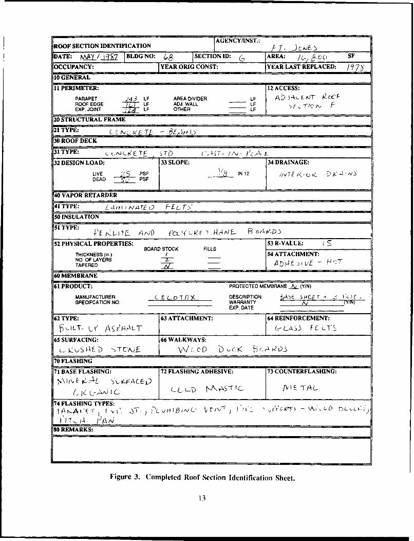
A Roof Section Folder should be established for each roof section containing a completed RoofSection Identification Sheet (Figure 3), and a Roof Inspection Worksheet (Figure 4). A roof sectionplan should be drawn to scale on the Roof Inspection Worksheet. The plan should show all physicalfeatures including perimeter conditions (roof edge, expansion joint, parapet wall, etc.), rooftopequipment, projections through the roof, roof drains, walkways, sign supports, and piping. The standardsymbols shown in Figure 5 should be used to identify these items whenever possible.
A master Roof Inspection Worksheet with an unmarked roof section plan should be kept in eachfolder. Copies of the Roof Inspection Worksheets (discussed in Chapter 3) are used to conductcondition evaluation inspections. They are filled out and stored in the Roof Section Folder. Roofdistresses or defects identified during the inspections are noted on the plan for future reference and tohelp determine maintenance and repair needs.
A blank Roof Inspection Worksheet is included in Appendix A of this report.
Inventory Data Collection
The information on the Building and Roof Section Identification Sheets can come from a varietyof sources. At installations with complete building records, most of the information can be taken from
*Metric conversion factors are on page 55.
10

ROOF SECTION FOLDERS FOREACH ROOF SECTION FOLLOWTHE BUILDING FOLDER
A BUILDING FOLDER ISPROVIDED FOR EACHBUILDING N
Figure 1. Example of a manual recordkeeping system.
as-built drawings, record drawings, and specifications. Because these drawings and specifications oftendo not show actual conditions, all data should be verified during the visual inspection. Core samplestaken for the purpose of verifying wet insulation (Chapter 4) should be used to determine thecomponents of the roof sections.
It is important that the collected information be as complete as possible. Missing data will makeanalysis and planning difficult. Although this phase does require some investment if time and effort,it needs to be done only once and then updated when changes to the roof sy stem occur.
Building Identification Sheet
The Building Identification Sheet (Figure 2) is kept in the Building Folder and gives generalinformation including building name, number, location, and occupancy. The Building IdentificationSheet also lists each roof section and its area, and the date of original construction of the building.Although some of the information is not directly relatcd to the roofing system, it does provide essentialdata for managing the network.
I II

BUILDING IDENTIFICATION AGENCY ST. NO.:
DATE: 4 / / 1 [AGENCY/INST.: FT .w&E E-
BUILDING NAME: c c.f c A I IuM
BUILDING NUMBER: o & DESIGN CATEGORY CODE '7 1 / ,
TYPECONST. I FACILITY NUMBER ic [ c (& i0 i
LOCATION: i - -J DE I V--D AVE.
USE: C.. Cc M T-.-IN IJ. YEAR BUILT:
ROOF SECTIONS:
A 4 2 L._ SF F zJK" SF K SF
.SF G SF L SF
c _74 _ SF H __ ____ SF M SF
D -4*'£ SF _ _ SF N SF
E iK SF J SF 0 SF
REMARKS:
Ac~g r- - K KTA(, lV - 'r,_ 4
- ~ ~ ~ !" EXT~~ DrJ&>~\C;Z-
G C2t4
BUILDING ROOF PLAN SCALE: I
Figure 2. Completed Building Identification Sheet.
12
AGENCY/INST.:
ROOF SECTION IDENTIFICATION AT 3"Y . T
DATE: Mkj.j_3/f. BLDG NO: SECTION ID: AREA: cc) SF
OCCUPANCY: YEAR ORIG CONST: YEAR LAST REPLACED: / 7)'
10 GENERAL
11 PERIMETER: 12 ACCESS:
PARAPET 24 3 LF AREA DIVIDER LF /.) )A 'E.JT gC . FROOF EDGE 7 LF ADJ. WALL LF .EXP. JOINT LF OTHER LF
20 STRUCTURAL FRAME
21 TYPE: c' TL -
30 ROOF DECK
31TYPE: L , rJc F LT ,40- uv* JKA.-
32 DESIGN LOAD: 33 SLOPE: 34 DRAINAGE:LE PSF IN 12DEAD L PSF
40 VAPOR RETARDER
41 TYPE: /J , /,, T W FEL T _
50 INSULATION
51 TYPE:
52 PHYSICAL PROPERTIES: 53 R-VAIUE:BOARD STOCK AILLS
THICKNESS (in.) 3 54 ATTACHMENT:NO. OF LAYERS -- A)PE vTAPERED -- IV -H:..7
60 MEMBRANE
61 PRODUCT: PROTECTED MEMBRANE k, (YIN)
MANUFACTURER C E L- "I - DESCRIPTION At s /4 E E r- f r- /r
SPECIFCATION NO. WARRANTY N (Y/NEXP. DATE
62 TYPE: 63 ATTACHMENT: 64 REINFORCEMENT:
A, ILT- A,., N I- ) LT (_.IS F-LT§
65 SURFACING: 66 WALKWAYS:
70 FLASHING
71 BASE FLASHING: 72 FLASHING ADHESIVE: 73 COUNTERFLASHING:A"I,, rL L F. C L -4.E 0 1
( I ,- ,j I c _. ( L L D ! .,,A t c. . fV E T L
74 FLASHING TYPES:\t-..A F. f * , '. E , ) F>L k 10 /AJ C',"( ' ,' o T - - \ .j (4) --,
SO REMARKS:
Figure 3. Completed Roof Section Identification Sheet.
13

I AGENCY/INST.:
ROOF INSPECTION WORKSHEET -.T J)OA/(S
BUILDING e PER. FLASHING -Z7 LF DATE
SECTION _ CURB FLASHING , LF NAME
BF-BASE FLASH PP-PITCH PANS SP-SPLITS PA-PATCHING I D S D 0MC-METAL CAP OR-DRAIN & SC HL-HOLES OV-DEBRIS & VEG D I E E TEM-EMBEDD MET BL-BLISTERS SR-SURF DET EQ-EQ SUPPORT S V F YFP-FLASHED PEN RG-RIDGES SL-SLIPPAGE PD-PONDING
I J
IFC r- 6 IVN
E3 4' EA#LK Y1_ #
SCALE: I" -30'
NORTH
Figure 4. Roof Inspection Worksheet with Roof Section Plan.
14

~H -- HATCH
E = EOUIPMENTP =PENTHOUSE
S : SKYLIGHT
SC =SOLAR COLLECTORT = TRANSFORMERV : VENTILATOR
or ANTENNA
A CORE SAMPLE WITH SAMPLE IDENTIFIER
0 VENT PIPE
* DRAIN OR DOWNSPOUT
LADDER
1: S SCUPPER
or CHIMNEY OR FLUE
PITCH PAN
o FLASHED PIPE
IL LIGHTNING ROD
ROOF EDGE
PARAPET WALL OR ADJACENT BLDG
EXPANSION JOINT OR ROOF DIVIDER
Figure 5. Symbols to be used on roof section plans.
15

Roof Section Identification Sheet
The Roof Section Identification Sheet (Figure 3) is completed for each roof section listed on theBuilding Identification Sheet and is kept in the corresponding Roof Section Folder. The sheet has eightmajor divisions and organizes the section data.
Roof Section Identification Worksheet
The three-page Roof Section Identification Worksheet (Figure 6) simplifies the task of collectingthe necessary data and ensures uniformity in reporting terminology. Most of the items are self-explanatory and the collection process only requires checking-off items pertaining to the roof section.Much of the data can be obtained from specifications, drawings, core cuts, and visual inspection.Some guidance is provided below. The information from these worksheets is transferred to the RoofSection Identification Sheet.
Descriptions of the collected inventory data follow:
General
Section 11 - Perimeter. The length (in feet) of the perimeter of the roof section categorized intothe listed construction "edges."
Section 12 - Access. The method used to gain access to the roof. Note whether the ladder isinside or outside the building and if it is permanently attached to the building. If it is not, a portableladder will be necessary for inspection. If access is from an adjacent roof section, identify the section.
Structural Frame
Section 21 - Type. The structural framing system which supports the roof section.
Roof Deck
Section 31 - Deck Type. The roof deck construction supporting the roofing system.
Section 32 - Design Load. The live and dead loads for the roof section. This information canusually be found on the building's structural drawings. Check in the general notes or in a special noteon the Roof Framing Plan.
Section 33 - Slope. The predominate slope of the roof section. The roof plan will generallyindicate the slope (e.g., 1/4 in. in 12 in.). If the slope is not noted on the roof plan, the sectiondrawings may indicate the slope. Measure the major slope if it cannot be found on the roof plan orsection drawings.
Section .34 - Drainage. The existing means of removing rainwater from the roof section. Checkthe roof section for interior drains, gutters, and downspouts. Determine whether leaders anddownspouts are connected to the scuppers. Check for overflow scuppers which control the height ofpondcd water and prevent overloading of the structure. ROOF EDGE indicates that the roof waterflows over the building edge to the ground or to a lower roof area without gutters or scuppers.
16

AG ENCY/IN ST.:ROOF SECTION IDENTIFICATION WORKSHEET r1 JCVAJE SDATE: MA) /Jj-7 1BLDG NO: I4 SECTION ID: ( ~JAREA: Enc SF
OCCUPANCY: c r ILE- YEAR ORIG CON ST: ___ YEAR LAST REPLACED:
10 GENERAL
11 PERIMETER:
PARAPET :24? LF EXP. JOINT / 4 LF ADJ. WALL LF
ROOF EDGE I'& / LF AREA DIVIDER ____LF OTHER LF
i12 ACCESS (check one):
INTERNAL LADDER EXTERNAL LADDER -_PENTHOUSEPermanent __Permanent
-Temporary -Temporary -X ACCESSED FROM ADJACENTROOF SECT (Sec. ID L)
[20 STRUCTURAL FRAME
21 TYPE (check one):
STEEL CONCRETE SPECIALBeams. Girders, Cols. X Beems _Dome
Long Sp Dock, Beams Flat Slab -Space FrameTrussesBar Joists With WOOD _UNKNOWN
Beams and Cola Laminated BeamsBar Joists With Trusses
Bearing Wells JoistsBar Joists With Panels
Combination
(30 ROOF DECK
yvFhekoe:NONCOMBUSTIBLE COMBUSTIBLE
-STEEL CONCRETE, L.W. -_WOOD BOARDSPrecast
CONCRETE. STD. __Cast-In-Place __PLYWOOD
Precast __Vermiculite
__at-.Plc Cellular -_WOOD FIBERK Cas-In-lacePedite
GYPSUMFiberboard Form CEMENT FIBERFiberglass Form _ Butb-Tees
-Gypsum Form -ClippedPrecast
32 DESIGN LOAD: LV 2 S N N WDEAD SDO PSF
33 SLOPE: V IN 12
34 DRAINAGE (check all): __ADJACENT ROOF SECTION
X INTERIOR DRAINS __SCUPPERS W/LEADERS AND DOWNSPOUTS
-GUTTERS & DOWNSPOUTS __OVERFLOW SCUPPERS
-SCUPPERS ROOF EDGE
40 VAPOR RETARDERJ
41 TYPE (check one):
-NONE _ COATED ROLL ROOFING _PVC
-ALUMINUJM FOIL __ LAMINATED ASPNIKRAFT __VINYL
-POLYETHYLENE LAMINATED FELTS UNKNOWN
Figure 6. Completed Roof Section Identification Worksheet.
17

SO INSULATION
S1 TYPE (check aD): __EXTRUDED POLYSTY. INSULATING FILLS__VemiIcIi
NONE _FOAMGLASS _Peite
__Cellular
-WOOD FIBERBOARD __PHENOLIC -Gypsum
__Lwt. ConcreteGLASS FIBER __POLYISOCYANURATE __Fill Type Unknown
~.PERLITE _CORK __UNKNOWN
SPOt.YURETHANE/BOARD -_FOAMED IN PLACE/PUF
EXPANDED POLYSTY.
52 PHYSICAL PROPERTIES: -NIA (No Insul.)
BOARD STOCK FOAMED IN PLACE AND INS. FILLS
TOTAL THICKNESS INCHES TOTAL THICKNESS ____INCHES
NO. OF LAYERS .- TAPERED ____(V/N)
TAPERED iJ (V/N)
53 R.VALUE (total): __UNKNOWN -N/A (No Insul.)
54 ATTACHMENT (board stock only)(check all):
MECHANICAL ~ADHESIVE-HOT __UNKNOWN
LOOSE LAID _ADHESIVE-COLD
60 MEMBRANE
61 PRODUCT: __UNKNOWN PROTECTED MEMBRANE h.. (V/N)
MANUFACTURER LEL r ~x DESCRIPTION 4E S r,-3PcYSPECIFICATION NO. __________ WARRANTY ±!LAYN) EXP DATE _
62 TYPE (check one): ROLL ROOFING UQUID APPLIED- Orgi~n. Surface -Neoprene/Hypalon
BIT. BUILT-UP __ Glas/Mmn. Surface _ Acrylic ElastoraSAsphalt _ Smooth -Butyl
Coal Tar Pitch~ - PolysulfideCold Process\ SINGLE-PLY __Urethane
Emulsion __EPDM SiliconeCold Process\ __CPE -Type Unknown
Cutback __CSPE
-Bit Type Uinknown __Pie PUF WITH COATING_PVC Silicone
MODIFIED BITUMEN -ButW_ Urethane-6 -B Neoprene _Catal. Urethane-APP _Nitrite -Acrylic
-Modifier Unknown -Type Unknown _Coaling Unknown
63 ATTACHMENT (for Single-Ply oniy)(cbeck one):
FULLY ADHERED __ PLATE/DISK/PARTIALLY ADHERED
LOOSEJBALLASTED MECH. FASTENERS-Penetrating-NonPenetrating
64 REINFORCEMENT (check one): MODIFIED BITUMEN & SINGLE-PLY_Polyester. Woven
BIT. BUILT-UP _Polyester, NonwovenOrgan c Fell __Glass
IGlass'Felt __Asbestos
Asbestos Fellt_ Flew*e, Synthetic-Fell Type Unknown Fell
__Laminate BackerPolyethylene
__Reinlorment Unknown__No Reinforcement
Figure 6. (Cont'd)
18

65 SURFACING (check one):
AGGREGATE SMOOTH __ MINERAL SURF. CAPRiver Gravel _ Cutback
IX Crushed Stone _ Emulsion __ LATEX COATING- Slag Hot Asphalt
Pea Gravel - Bit Type Unknown PAVERSVolcanic Rock ConcreteMarble Chip _ REFLECTIVE __ CompositeLimestoneAluminum Granule _ ELASTOMERIC -OTHERMineral GranuleAgg. Unknown - METAL SKIN __ NONE
6 WALKWAYS (check all): _RUBBER MAT
-ASPHALT PLANK Y WOOD DUCK BOARDS __ OTHER
-CONCRETE PAVERS MINERAL SURFACED FELTS _ NONE
170 FLASHING71 BASE FLASHING (check al1):
MINERAL SURFACED MODIFIED BITUMEN __ PVC COVERED METAL,. Organic _ Granule Surface
Glass __ Foil Surface METALFabric Unknown Smooth Surface
CPEREINFORCED ASBESTOS __ VINYL
CSPEFIBERGLASS __ PVC
NONE-COTTON _ NEOPRENE
UNKNOWNBURLAP _ EPDM
72 FLASHING ADHESIVE (check one):
- HOT MOPPED __ TORCH APPLIED
"COLD MASTIC __ UNKNOWN
73 COUNTERFLASHING (check all):
Z METAL __ FLEXIBLE
BITUMINOUS NONE
74 FLASHING TYPES (check all):
ROOF EDGE _ ROOF PENETRATION 'PITCH PAN- Embedded Edge Met.
Metal Cap Flash. ROOF RELIEF VENT PIPE SUPPORTS- .X Wood Blocks
_WALUPARAPET _PLUMBING VENT _ Rollers
COPING EOUIPMENT SUPPORTStructural Frame
-AREA DIVIDER __ CurbsConduit
EXPANSION JOINT __ Wood SleepersMetal Cover None (unflashed)Flexible Cover
80 REMARKS
Figure 6. (Cont'd)
19

Vapor Retarder
Section 41 - Type. The material type used in reducing vapor transmission through the roofingsystem (sometimes referred to as vapor barrier). This information can usually be found in thespecifications or on construction drawings. If needed, determine the presence and type of vaporretarder from core cuts.
Insulation
Section 51 - Type. Type(s) of insulation used in the roofing system.
Section 52 - Physical Properties. The total thickness and number of layers of insulation. Alsoindicate if the insulation system is tapered. Core samples are the best means of determining insulationtype and thickness. Check specifications or contracts for information concerning whether insulation wastapered to provide slope, and if multiple layers were used.
Section 53 - R-value. The total R-value (thermal resistance) of the insulation. Checkspecifications, manufacturer's information, or use industry accepted values.
Section 54 - Attachment. The method used for attachment of the roof insulation. This informationshould be in the specifications. The insulation on roofs installed before 1982 was frequently attachedwith mechanical fasteners on the perimeter of steel decks and adhesive on the field of the roof. Enterail methods if more than one method was used. Single-ply ballasted systems are generally installedwith the insulation loose-laid.
Membrane
Section 61 - Product. The manufacturer, product description and specification of the roofmembrane. Construction drawings or contractor submittals are the only reliable source for thisinformation. Also indicate if the roof assembly is a protected membrane (insulation on top ofmembrane).
Section 62 - Type. The type of material used as the membrane. The contract specifications orshop drawing file will be the best sources for this data. For built-up roofs, a simple method fordetermining bitumen type is described in Appendix B.
Section 63 - Attachment. The method of membrane attachment (for single-ply membranes only).The contract specifications or shop drawings are the best sources for this information.
Section 64 - Reinforcement. Type of fabric or reinforcement used in the membrane. Contractspecifications and manufacturer's literature are the best sources for this information.
Section 65 - Surfacing. Type of surfacing on the membrane providing protection or ballast.Visual observations or the contract specifications are the best sources for this information. If morethan one surfacing appears on the roof section, consider dividing it into multiple sections.
Section 66 - Walkways. Type(s) of walkways used on the roof section. Check the roof section
plan to be sure they are shown.
Flashing
Section 71 - Base Flashing. Types of base flashing that are present. The contract specificationsor contractor's submittals and visual observation arc the best sources for this information.
20

Section 72 - Flashing Adhesive. The adhesive used to apply the base flashing. The contractspecifications should provide this information.
Section 73 - Counterflashing. Types of counterflashing present on the roof section. The contractspecification, contractor shop drawings, and visual observation are the best sources for this information.
Section 74 - Flashing Types. Types of flashing details existing on the roof section. There willnormally be several flashing types on every roof. Check off all types that are present. Check the roofsection plan to be sure that all of the existing flashing, especially penetrations, pitch pans, and pipesupports are shown.
Remarks
Additional information that will be useful to the planners in scheduling maintenance orreplacement. If the roof system was placed over an existing roof, it should be stated in this section.
21

3 VISUAL INSPECTION AND EVALUATION PROCEDURE
The visual roof condition evaluation procedure is the critical component of ROOFER. The dataobtained during the procedure is combined with the insulation inspection data (Chapter 4) to providean overall assessment of the roof condition and determine MRR requirements. This chapter brieflyexplains the visual inspection procedure and the methods used to calculate the membrane and flashingcondition indexes (MCI and FCI). A complete description of the visual inspection procedure can befound in USACERL Technical Report M-87/13' which provides the necessary guidance to perform theinspections and is the standardized reference for distress/defect identification.
Membrane and Flashing Condition Ratings
The membrane and flashing components are rated separately by direct measurement of thedistresses found in each component. Treating each component separately provides a more accurateassessment of component condition, needed repair, and waterproof integrity. MCI and FCI ratings arenumerical indicators based on a scale of 1 to 100. The scale and associated ratings are shown inFigure 7.
Inspection Procedure
The inspection and recording can be accomplished by one individual. However, for safety reasons,a second individual should assist the inspector. During initial implementation, a third team membercan help develop the roof section plan and take core samples. Each roof section is carefully inspected,and flashing and membrane distresses are recorded on a Roof Inspection Worksheet (Figure 8). Thetotal perimeter flashing length should be determined and recorded in the space provided in the heading.The curb flashing, which includes the length of the base flashing on all curbed projections such asequipment supports, should also be determined and recorded in the heading. The problems areidentified by distress type, severity level, specific defect, and quantity. A description of the blisterdistress and specific defects is shown in Figure 9. Similar detailed descriptions for all other membraneand flashing distresses are presented in USACERL Technical Report M-87/13 4. Figure 10 contains anabbreviated list of identifiers for all the distresses/defects associated with the ROOFER inspectionprocess. The list can be attached to the bottom of a long clipboard for ready reference by theinspector to identify specific defects in each distress category (i.e., Base Flashing - High - Holes, splits,and tears, would be identified as BF-H- 1 on the Roof Inspection Worksheet). If a roof moisture surveyof the insulation (see Chapter 4) was completed before the visual inspection, mark the core samplelocations at this time.
As part of the visual inspection, a survey of the interior and exterior conditions should beperformed, The inspector shall complete the reverse side of the Roof Inspection Workshcet (Figure11) and record in the "remarks" section any additional comments that would alert the manager ofproblems that should be further investigated and corrected.
M. Y. Shahin, D. M. Bailey, and D. E. Brotherson.
4M. Y. Shahin, D. M. Bailey, and D. E. Brotherson.
22

MCI orFCI RATING
100
O EXCELLENT
85
VERY GOOD
70
0GOOD
FAIR
40
POOR
25
VERY POOR
10FAILED
0
Figure 7. MCI and FCI and ratings.
Calculating the MCI and FCI from Inspection Results
The MCI and FCI of a roof section is determined from the information recorded on the RoofInspection Workshcct. The calculations are completed on the Roof Section Rating Form (Figure 12)using the following live step procedure (also shown in Figure 13):
Step I
Transfer the quantities for each combination of distress type and severity level to the Roof SectionRating Form.
23

BUILDING PER. FLASHING 152.7 _LF DATE l'AA' 191,'
SECTION CCURB FLASHING ~LF NAME 1Z. S r'A \T 4
BF-BASE FLASH PP-PITCH PANS SP.SPLITS PA-PATCHING I D IS D aMC-METAL CAP DR-DRAIN & SC HL-HOLES Dy-DEBRIS & VEG D I E E TEM-EMBEDO MET BL-BLISTERS SR-SURF DET EO-EO SUPPORT S V F YFP-FLASHED PEN RG-RIDGES SL-SLIPPAGE PD-PONDING 0
L
; NNC 1 2
Pv_ L I_
V I FP _ _
P LW LI
0 .Lj~<VA _ zs
3'(
C0)
* 4Z L I
rSCALE: V' -;o
OT
Figure 8. Completed Roof Inspection Worksheet.
24
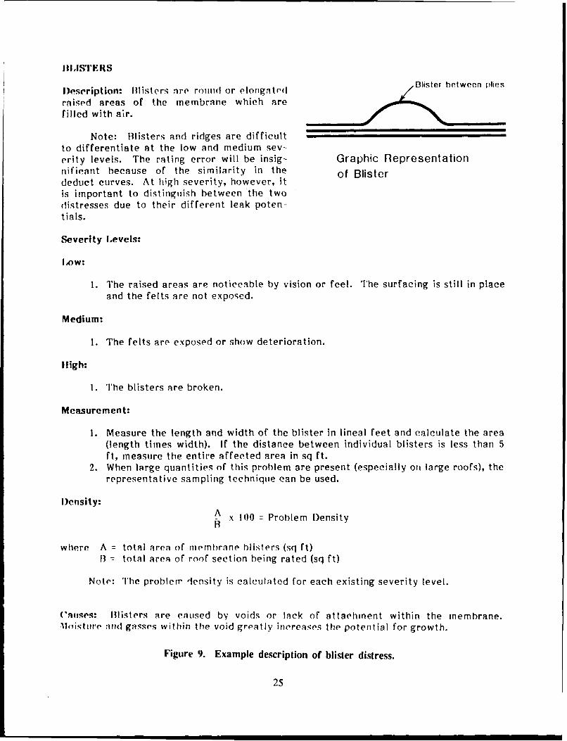
IlI,IsIrEIIS
)es eription: illisters are round or elongated Blister between plies
raised areas of the membrane which arefilled with air.
Note: Blisters and ridges are difficultto differentiate at the low and medium sev-erity levels. The rating error will be insig- Graphic Representationnifieant because of the similarity in the of Blisterdeduct curves. At high severity, however, itis important to distinguish between the twodistresses due to their different leak poten-tials.
Severity Levels:
Low:
1. The raised areas are noticeable by vision or feel. The surfacing is still in placeand the felts are not exposed.
Medium:
1. The felts are exposed or show deterioration.
lligh:
1. The blisters are broken.
Measurement:
1. Measure the length and width of the blister in lineal feet and calculate the area(length times width). If the distance between individual blisters is less than 5ft, measure the entire affected area in sq ft.
2. When large quantities of this problem are present (especially ont large roofs), therepresentative sampling technique can be used.
Density:A x 10)0 Problem Density
where A = total area of iernhren blisters (sq ft)13- total area of roof section being rated (sq ft)
Note: The problem density is caleulAted for each existing severity level.
Cau.es: Blisters are caused by voids or lack of attachment within the membrane.Moisture and gasses within the void greatly increases the potential for growth.
Figure 9. Example description of blister distress.
25

FLASHING DISTRESSES/DEFECTS MEMBRANE DISTRESSES/DEFECTS
BF-LOW EM. HIGH BL-LOW SL-LOW1. Loss surface-NO DET 1. Felts missing 1. Visible-NOT BARE 1. Exists < 2"2. < 6" high 2. Splits at joints BL-MED SL-HIGH3, Permanent repairs 3. Holes in metal 1. Felts exposed 1. Exists >2"
BF-MED 4. Loose-deteriorated felts BL-HIGH PA-LOW1. Slip. wrink, loose 5. Holes-interior gutter 1. Felts broken 1. Visible2. Loss surface-DET FP-LOW RG-LOW PA-MED3. Grease-NO DET 1. Sleeve deformed 1. Visible-NOT BARE 1. Not equal to existing4. Temp. repairs 2. < 6" RG-MED PA-HIGH
BF-HIGH FP-MED 1. Felts exposed 1. Other distress in patch1. Holes, splits, tears 1. Felt exposed RG-HIGH DV-MED2. Gap-top, side 2. Top not sealed 1. Break at top 1. Material on roof3. Grease-DET 3. Sleeve open, no umbrella 2. Top felt deteriorated 2. Solvent/oil/grease-NO DET
MC-LOW 4. Metal corrosion SP-HIGI-' 3 Vegetaoion-NO PENETRATION1. Paint.light corrosion FP-HIGH 1. Open split DV-HIGH2. Cap deformed 1. No strip felt HL-HIGH 1. Solvent/oil/grease-DET3 CtrFI deformed 2. Sleeve cracked 1. Hole in membrane 2. Roots in felts4. CtrFI sealed to base 3. No sleeve SR-LOW EQ-LOW
MC-MED 4. No seal at membrane 1 Poor aggregate embedment 1. Exists1. Holes-vert surface PP-LOW 2. Open laps, fishmouths EQ-MED2. Cap loose, Its open 1. Exist 3. Alligatoring startng 1. Movement of support-NO DAM3. Sealant bad PP-HIGH 4. Walkways-cracked,blister 2. Bolts-SEALED4. CtrFI loose 1. Corrosion SR-MED EQ-HIGH5. CtrFI not over BaseFI 2. Seal below rim 1. Flood coat exposed 1. Movement of support-DAMAGE
MC-HIGH 3. Felts-DET 2. MC-felt exposed 2. Bolts-NOT SEALED1. Cap/rtrFI missing 4. Seal cracked, separatwd 3. SM-no coating PD-LOW2. Holes ior surface DR-LOW 4 SM-alligatoring to felt 1. Exists or evidence3. Jt.Co- missing 1. Bitumen Flow-NO CLOG SR-HIGH
EM-LOW DR-MED 1. Felts exposed1. Exists 1. Felt exposed 2. MS-felt deteriorated
EM-MED 2. Strainer broken 3, SM-alligatonng thru felt1. Joints exist 3. Scupper corroded 4. Walkway membrane torn2. Nails backing out DR-HIGH3 Corrosion 1. Felt-DET INSULATION DISTRESS/DEFECT4 Loose-NO DET 2. Ring loose/missing
3. Clogged INS-HIGH4. Scupper metal has hole 1. Wet insulation
Figure 10. List of distress/defect identifiers.
Step 2
Total the quantities for each distress/severity level combination, calculate the density values, anddetermine the Deduct Values (DV) from the Deduct Value Curves. Appendix C contains Deduct ValueCurves for the 16 distress types.
Step 3
Treating the flashing and membrane distresses separately, list the individual deduct values for eachcomponent (flashing and membrane) in descending order and compute the sum of the deduct values(SDV) and the number of deducts greater than I (q), as shown on page 30. Determine thecorresponding Corrected Deduct Values (CDV) from the Corrected Deduct Value Curves (AppendixC). (Note: different Corrected Deduct Value Curves are used for the membrane and the flashing.)The CDV of maximum value should be used to compute the condition index.
26

ROOF INSPECTION WORKSHEET - COMMENTS
[ISTR;UCTIONS: Circle response, i.e., Y = yes, N = no or U = unknown ornot observed. If Y.(yes), circle the type of problem.
A. EVALUATION OF INTERIOR CONDITIONS
1. Does the roof leak? Describe: 'ys. NF c orn er N U
2. Are there water stains on: N Ua. walls 0 deck e. structural elementsb. ceilings . floor f. other:
3. Do structural elements show any of the following: N U& cracks d. alteration g. physical damageb. splits e. rotting h. insect damagec. spalling f. settlement i. other:
4. Does the underside of the deck show any of the following: &9 N Ua. rusting 0 spalling e. saggingb. rotting d. cracks f. other
B. EVALUATION OF EXTERIOR CONDITIONS
1. Do the exterior walls shown any of the following: Ya. cracks c. spalling e. water stainsb. rusting d. movement f. other:
2. Does the fascia or soffit show any of the following: Na. cracks c. spalling e. water stainsb. rusting peeling f. other:
3. Do the gutters or downspouts show any of the following: Ya. loose c. missing e. cloggedb. damaged d. disconnect f. other:
C. EVALUATION OF ROOFTOP CONDITIONS
1. Is there any unauthorized, unnecessary, or improperly Ninstalled equipment on the roof?a. equipment 0 antennas e. cablesb. signs d. platforms f. other:
2. Do adjacent parapet walls show any of the following: Ya. cracks c. cap cracked e. sealantb. spalling d. cap missing f. other:
D. REMARKS:
Figure 1. Reverse side of the Roof Inspection Worksheet.
27

ROOF SECTION RATING FORMBUILDING (00 SECTION 6& DATE Z, ,' CAS.Y
PER. FLASHING 627 LF FLASHING CT YCURB FLASHING Z LF TOTAL _LF AREA 1 0J0 0.-) SF
FLASHING MEMBRANE
DISTRESS TYPES DISTRESS TYPESBF - BASE FLASH DR - DRAIN & BL- BUSTERS SL - SUPPAGEMC - METAL CAP SCUPPER RG - RIDGES PA - PATCHINGEM - EMBEDDED MET SP - SPUTS DV - DEBRIS & VEGFP - FLASHED PEN HL- HOLES EQ - EQU SUPPORTSPP- PITCH PANS SR- SURF DET PD- PONDING
TYP SV QUANTITIES TOT DEN DV 'IYP SV QUANTITIES TOT DEN DV
C F L VALE (D3 V3 4- 17 9L L 4EUTz VAU (Mc. i . /L) '7 =3 F F CD L 7
__3 :j H -3_______ IL?, C>' ~.LA P I 2- I z 0 CA N . ,Iz -
D R L- li s.A I I&m 4 00 T I 0!- ~ Q 3A 1PP H ,8 11 I -o.I. sc~.~
i ur 2 0Co p Let ' Rti i orbm.
CORRECTED DEDUCT VALUE (CDV) 132 CORRECTED DEDUCT VALUE (CDV) C
FCI =100 -CDV= MCI =100 -CDV= 3____FLASHING RATING (S 00: MEMBRANE RATING Po ______
Figure 12. Completed Roof Section Rating Form.
28

STEP 1. INSPECT ROOF. DETERMINE DISTRESS TYPES AND SEVERITY LEVELS;DETERMINE QUANTITIES AND CALCULATE DENSITIES.
MVEMBRANE RIDGES
MEMBRANE BLISTERS
STEP 2. DETERMINE DEDUCT VALUES.
sor am4avH -i flii 1IT~ DY -
-414~~TE 5 DEEMN MEMBRANE Ia iR H
f fj4MR0V 11 11
so so
Gal ;0 0
*frV08 ,0af ac
loo.
_________________________*am*oO 40 4 00 40 ~
'1010' ~ lS PO
VhLI
STEP~ ~~~~~~~~~1-- 4 OPT MMRN ONIININE MI. 0-D
Figre 3. tep fr clcuatig CI nd CI ora rof ecton
29G

Flashing
(Distress data from the Completed Roof Section Rating Form (Figure 10])
DV SDV q CDVflashing
21 21 1 21
17 38 2 24
13 51 3 28
13 64 4 32
11 75 5 33
9 84 6 33
2 86 7 32
1 87 7 31
Maximum CDVflashing =33
Membrane
(Distress data from the Completed Roof Section Rating Form [Figure 10])
DV SDV q CDVmembrane
65 65 1 65
14 79 2 55
7 86 3 53
5 91 4 48
3 94 5 47
3 97 6 43
3 100 7 40
2 102 8 37
2 104 9 38
2 106 10 38
Maximum CDVmembrane = 65
30

Step 4
Calculate the condition indexes using the following equations:
FCI = 100 - Max. CDV (flashing) [Eq 1]
MCI 100 - Max. CDV (membrane) [Eq 2]
Step 5
Determine the corresponding descriptive condition ratings from Figure 7 for both indexes.
Use information from the Roof Inspection Worksheet to complete the heading section of the RoofSection Rating Form. Building, section, and agency/installation data is essential to provide continuityin the various forms. File the completed Roof Section Rating Form in the corresponding Roof SectionFolder.
31

4 INSULATION INSPECTION AND EVALUATION PROCEDURE
A complete evaluation of an insulated roofing system requires that the insulation be inspected todetermine if it contains moisture. This chapter describes the effects of wet insulation, the insulationcondition rating procedure, moisture detection methods, and the determination of the InsulationCondition Index (ICI).
Insulation Condition Rating
The insulation condition rating is based on the Insulation Condition Index (ICI). The ICI, anumerical indicator between 0 and 100, reflects the condition of the insulation in terms of its abilityto perform its function and the level of needed repair. Insulation with an ICI of 100 is in excellentcondition.
Effects of Wet Insulation
Insulation is a common component of many low-slope roofing systems. Defects in the membraneand/or flashing components can provide paths for water to enter and wet the insulation. Moisture inthe insulation can also be caused by condensation. Moisture reduces the R-value of the insulation andmay also reduce the bond between it and the membrane. Roofs with wet insulation are more proneto blow off or split. Water in insulation adds to the weight the structural system must resist and mayalso promote corrosion of fasteners or metal decks, rotting of wood decks and nailers, and deteriora-tion of cementitious deck materials.
Roof Moisture Detection
Rooftop conditions that could suggest wet insulation include spongy areas, depressions in the roofsurface, vegetation growing through the membrane, and leaks that continue to drip long after the sourceof water has been removed from the roof.
Detecting wet insulation and determining the extent of the wet area can be done using anondestructive moisture detection technique such as infrared (IR) scans, nuclear meter, or capacitancemeter. The results of a moisture survey using any of these techniques must always be verified by coresampling.'
Infrared Scanning
IR scanning systems detect the temperature differences that occur on a roof above areas of wetand dry insulation. IR roof scans should be performed at night and can either be accomplished on theroof or from the air. When surveying only a few roofs in an area, on-the-roof scans may be more cost
'W. Tobiasson and C. Korhonen, Roof Moisture Surveys: Yesterday, Today and Tomorrow, CRRELMiscellaneous Paper 2040 (U.S. Army Cold Regions Research and Engineering Laboratory [CRRELI,September 1985).
32

effective than aerial scans. In many instances, however, an aerial IR scan is more cost effectivebecause all the insulated roofing systems of most military installations can be surveyed in a few hours.6
A thermal image (thermogram) of a roof taken during an on-the-roof survey is shown in Figure14. The bright thermal anomalies indicate where insulation is wet. Figure 15 is a conventionalphotograph of the same roof. The thermogram in Figure 16 was taken from an Army helicopter about500 ft above a roof. Bright areas denote potentially wet areas of insulation as well as areas havinghot rooftop equipment or exhaust coming from roof vents.
Aerial scans are usually done from a helicopter but can also be done using a fixed-wing aircraft.The thermal images taken from the air are recorded on film or videotape for subsequent review andanalysis. Later, the areas that appear to contain wet insulation may be marked on airphotos (Figure17).
Nuclear Meter
Nuclear meters detect moisture by measuring the increased number of hydrogen atoms that occurin areas of wet insulation. Readings are taken on a grid pattern (the grid is normally 5 ft by 5 ft)established on the roof. The differences in the meter readings are analyzed and interpreted, and amoisture contour map of the roof is drawn to delineate potentially wet areas. Computers are often usedto analyze the data and develop the contour map, greatly reducing the time involved.
Capacitance Meter
Capacitance meters measure the differences that occur in dielectric properties between areas of wetand dry insulation. Capacitance meter readings are also taken on a grid pattern that is normally 5 ftby 5 ft. The differences in the meter readings are analyzed and interpreted, and a moisture contourmap is drawn.
Core Sampling and Determining Moisture Content
After the moisture detection work is completed, the areas of potentially wet insulation are plottedon the roof section plan of a Roof Inspection Worksheet (Figure 18). The areas of potentially wetinsulation are shown by hatchmarks.
Since the moisture detection techniques discussed above provide only relative results, core samplesfrom the roof system must be taken and analyzed to determine the amount of moisture actually presentin the insulation.
Proposed core sample locations are selected for areas of potentially wet insulation and markedon the Roof Inspection Workshect as triangles. Usually, a core sample should be taken for eachpotentially wet area. However, when small areas are found near a large area, one core sample canbe assumed to represent those areas as well. One additional core sample is always taken in a dry areaas well, to verify that it is indeed dry and not just less wet. The core sample locations can be verycritical. A core sample taken at a presumably wet location on the roof section could easily indicate
6W. Tobiasson, Aerial Roof Moisture Surveys, CRREL Miscellaneous Paper 2022 (CRREL, August1985); W. Tobiasson, A Method for Conducting Airhorn Infrared Roof Moisture Surveys, CRRELMiscellaneous Paper 2436 (CRREL, April 1988).
33
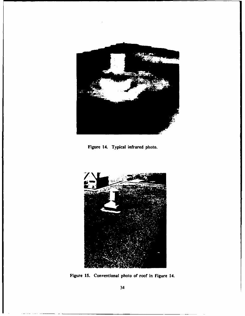
Figure 14. Typical infrared photo.
Figure IS. Conventional photo of roof in Figure 14.
34

Figure 16. Aerial thermogram of a roof.
Figure 17. Airphoto marked to show potential areas of wet insulation.
35

BUILDING 6,1 PER.FLASHING S5ZI LF DATE 1 ,q /9SECTION 6CURB FLASHING -5&LFNAEke
SF-BASE FLASH PP-PITCH PANS SP-SPLITS PA-PATCHING I D S D 01MC-METAL CAP DR-DRAIN & SC HL-H-OLES DV-DEBRIS & VEG D E E TEM-EMIEDO MET 9L-BLUSTERS SR-SURF DET EQ-EQ SUPPORT S V F YFP-FLASNED PEN RG-RID(3ES SL-SLIPPAGE PD-PONDING
V'-'~ CofE A." tro 9.fpiE5Et'T 15art4 AIZFP^
3'.-4!---
'SE ~ ~ ': G' 4 IRV- -
\.r, Coke "C
rn *4WA W1 sA Y
SCALE: I 0NORTH
Figure 18. Potentially wet areas and core sample locations mapped onto
Roof Inspection Worksheet.
36
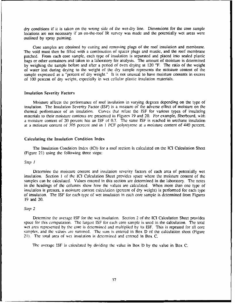
dry conditions if it is taken on the wrong side of the wet-dry line. Dimensions for the core samplelocations are not necessary if an on-the-roof IR survey was made and the potentially wet areas wereoutlined by spray painting.
Core samples are obtained by cutting and removing plugs of the roof insulation and membrane.The void must then be filled with a combination of spacer plugs and mastic, and the roof membranepatched. From each core sample, each type of insulation is separated and placed into sealed plasticbags or other containers and taken to a laboratory for analysis. The amount of moisture is determinedby weighing the sample before and after a period of oven drying at 120 'F. The ratio of the weightof water lost during drying to the weight of the dry sample represents the moisture content of thesample expressed as a "percent of dry weight." It is not unusual to have moisture contents in excessof 100 percent of dry weight, especially in wet cellular plastic insulation materials.
Insulation Severity Factors
Moisture affects the performance of roof insulation in varying degrees depending on the type ofinsulation. The Insulation Severity Factor (ISF) is a measure of the adverse effect of moisture on thethermal performance of an insulation. Curves that relate the ISF for various types of insulatingmaterials to their moisture contents are presented in Figures 19 and 20. For example, fiberboard, witha moisture content of 20 percent has an ISF of 0.7. The same ISF is reached in urethane insulationat a moisture content of 305 percent and in I PCF polystyrene at a moisture content of 440 percent.
Calculating the Insulation Condition Index
The Insulation Condition Index (ICI) for a roof section is calculated on the ICI Calculation Sheet(Figure 21) using the following three steps:
Step I
Determine the moisture content and insulation severity factors of each area of potentially wetinsulation. Section 1 of the ICI Calculation Sheet provides space where the moisture content of thesamples can be calculated. Values entered in this section are determined in the laboratory. The notesin the headings of the columns show how the values are calculated. When more than one type ofinsulation is present, a moisture content calculation (percent of dry weight) is performed for each typeof insulation. The ISF for each type of wet insulation in each core sample is determined from Figures19 and 20.
Step 2
Determine the average ISF for the wet insulation. Section 2 of the ICI Calculation Sheet providesspace for this computation. The largest ISF for each core sample is used in the calculation. The totalwet area represented by the core is determined and multiplied by its ISF. This is repeated for all coresamples, and the values are summed. The sum is entered in Box D of the calculation sheet (Figure21). The total area of wet insulation is determined and entered in Box C.
The average ISF is calculated by dividing the value in Box D by the value in Box C.
37

500.000
glass fIbrpoyrtaepoytrnadoyioynreinuto.
G""AS 3 7 1 ,I1 /, ,t1110.80
S P-L C'P LU H 100- F, 'L~ "f!tt I-
0,4 ik- ' C l l /f //ICAN / S]
0.00 I t
It ' ;TYR _l
10 50 to0 500 1000 5000 10000
MOISTURE CONTENT (5 DRY WEIGHT)
Figure 19. Insulaion severity factor (ISF) vs moisture content for cellular glass, cork,glass fiber, polyurethane, polystyrene, and polyisocyanurate insulation.
0.803
060-INSL ATIN G
u_ CONCREITE 7
0.40 7: ;Uiml- P - , 1I L t
0.20 /C 1HI
tO 1 50 100 500 1000
MOISTLJRE CONTENT (% DRY WEIGHT)
Figure 20. ISF vs moisture content for phenolic, insulating concrete, gypsum, perlite,and fiberboard insulation.
38

GECY/INST.:ICI CALCULATION SHEET - % 2
DATE: .5 12S / j__L. BLDG. NO.: I SECTION: AE: // O S
MC CALC. BY: ,VVIL irS ISF & ICI CALC. BY: W_ , _C____
1. DETERMINATION OF MOISTURE CONTENT AND INDIVIDUAL ISF OF CORE SAMPLES
A B C D E F %WATERCORE INSULATION THICK TARE WET+ DRY+ WET DRY WATER (F/E) ISF
TYPE WT TARE TARE (B-A) (C-A) (D-E) X 100
AKTOTA LE -2 /A-13 AL AR54 100
r, ~ K>--~ _ _9,./ i2.2 .(,q5 2~ 73 5 z _,_ 37
If , 7 .J
C ~E7~4~ Z/ 7S z/5 421 15c5 I/S c .cc
1 l)3,1 /t' O 2c 21,3S V YVR, ,7F
2. DETERMINATION OF AVERAGE 1SF 3. DETERMINATION OF ICI
CORE 1SF WET AREA (A)X(B) PROBLEM DENSITY: .(A) AB
(TOTAL WET AREA / TOTAL AREA) X 100
A I 0E LL/ DV: 20
k _ _ 04 WAF: _O__
ICI: __ __ _ __ _
100 - [ (IDy + WAF) X AVERAGE 1SFI
TOTALS (C0) 2 (0) Z L(4q r
AVERAGE 1SF (0)1(C) O' 1 RATING: P-009
...... . 1 41 I5 F I
1. DETERMINE THE ISF FOR EACH COMPONENT OF COMPOSITE INSULATION;FOR EACH CORE USE THE LARGEST 1SF WHEN DETERMINING THE AVERAGE IS4.
2. DO NOT INCLUDE ANY AREAS THAT HAVE AN 1SF OF ZERO
3. ROUND ICI TO NEAREST WHOLE NUMBER.
WE'T AREA FACTOR (WAF I I NSULATION CONDITION RATING
WET AREAS WAF ICI
1 0 86 -100 EXCELLENT
2 4 71 85 VERY GOOD
3 6 56- 70 GOOD
0- ..------- ~~ 41 - 55 FAIR
6 OR MORE 10 26 40 POOR11 25 VERY POOR
0 10 FAILED
Figure 21. Completed ICI Calculation Sheet.
39

Step 3
Determine the ICI ior the roof section. Section 3 of the ICI Calculation Sheet provides space for thecalculation. The problem density is determined using the following equation:
Problem Density = x 100 [Eq 3]Area
where C = Total area of wet insulation
Area = Total area of roof section being rated.
The Insulation Deduct Value (IDV) is then determined from Figure 22 and the ICI is calculated using the
following equation:
ICI = 100 - [(IDV + WAF) x ISFAve] [Eq 4]
where IDV = Insulation Deduct Value from Figure 22
WAF = Wet Area Factor, (use the following to adjust the index to account forthe number of wet areas present*)
No. of wet areas 1 2 3 4 5ormoreWAF 0 4 6 8 10
ISFAve = The Average Insulation Severity Factor determined from Step 2
The insulation condition rating is then selected from the table at the bottom of the calculation sheet(Figure 21). In the example shown, the ICI is 23 (rounded to the nearest whole number), and the ratingis "very poor."
Looking at the computation, one can see that a roof section with 17.1 percent wet insulation wouldbe "very poor" in terms of the ability of the insulation to perform. If the wet insulation were all locatedin one contiguous area, then the WAF would be "0" and the ICI would increase to 31 and the roof sectionwould be rated as "poor" with regard to insulation.
*This is the actual number of separate wet areas or potentially wet areas on the roof section and not neces-sarily the number of core samples used to represent these wet areas. For the example shown in Figurc18, the number of wet areas is four. The core location B found the potential wet area to be dry.
40

w 80- - - - - - *- -
<- 70--60° [I Il IV I 1]i1
40 4-
o 30------
~20---- --- _
IDL- 1-- I- --o - -- - -001 0.05 0.1 0.5 1 5 10 50 100
DENSITY (%)
Figure 22. Insulation deduct value (IDV) vs problem density.
41

5 ROOF CONDITION EVALUATION AND MAINTENANCE,REPAIR, AND REPLACEMENT (MRR) PROCEDURES
The membrane, flashing, and insulation condition indexes, in total, provide an assessment of thecondition of a roof section. By combining these three indexes, a roof condition index (RCI) isproduced. This single index is useful for evaluating the overall condition of a roof section and forcomparing conditions between roof sections. The RCI allows the user to rank individual roof sectionsin accordance with their ability to perform.
The three component indexes (FCI, MCI, and ICI) have a direct relationship to determining theneeds for MRR of the various roof sections. The RCI similarly provides an overall indication of MRRneeds for the entire roof network. This chapter will describe the method used to develop the rela-tionship between the RCI and the three component indexes. It will also illustrate how MRRalternatives can be determined for the individual roof sections.
Roof Condition Index Calculation
Each individual index (MCI, FCI, ICI) reflects the component's ability to provide its intendedservice and indicates MRR needs. Since the components must interact to function as a roof system,they are dependent on each other. This relationship is defined for roof sections with insulation by thefollowing equation:
RCI = (0.7 x lowest condition index) + [Eq 5](0.15 x Sum of remaining condition indexes)
If a nondestructive moisture survey of an insulated roof section has not been conducted, an ICIof 100 is assumed. In this case, the RCI may not be an accurate index.
If the roof section has no insulation, the RCI is determined by the following equation:
RCI = (0.7 x Lowest condition index) + [Eq 6](0.3 x Remaining condition index)
The above equations give the greatest weight to the component with the lowest condition index andthen modify it by adding "value" from the remaining indexes.
The following examples illustrate how this relationship works:
Example 1: FCI = 67; MCI = 35; ICI = 23
RCI = (0.7 x 23) + 0.15 (67 + 35)= 16 + 15= 31
Example 2: FCI = 67; MCI = 35 ; ICI = 100
RCI = (0.7 x 35) + 0.15 (67 + 100)= 25 + 25= 50
42
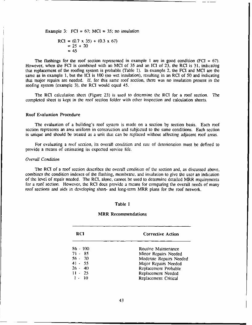
Example 3: FCI = 67; MCI = 35; no insulation
RCI = (0.7 x 35) + (0.3 x 67)= 25 + 20= 45
The flashings for the roof section represented in example I are in good condition (FCI = 67).However, when the FCI is combined with an MCI of 35 and an ICI of 23, the RCI is 31, indicatingthat replacement of the roofing system is probable (Table 1). In example 2, the FCI and MCI are thesame as in example 1, but the ICI is 100 (no wet insulation), resulting in an RCI of 50 and indicatingthat major repairs are needed. If, for this same roof section, there was no insulation present in theroofing system (example 3), the RCI would equal 45.
The RCI calculation sheet (Figure 23) is used to determine the RCI for a roof section. Thecompleted sheet is kept in the roof section folder with other inspection and calculation sheets.
Roof Evaluation Procedure
The evaluation of a building's roof system is made on a section by section basis. Each roofsection represents an area uniform in construction and subjected to the same conditions. Each sectionis unique and should be treated as a unit that can be replaced without affecting adjacent roof areas.
For evaluating a roof section, its overall condition and rate of deterioration must be defined to
provide a means of estimating its expected service life.
Overall Condition
The RCI of a roof section describes the overall condition of the section and, as discussed above,combines the condition indexes of the flashing, membrane, and insulation to give the user an indicationof the level of repair needed. The RCI, alone, cannot be used to determine detailed MRR requirementsfor a roof section. However, the RCI does provide a means for comparing the overall needs of manyroof sections and aids in developing short- and long-term MRR plans for the roof network.
Table 1
MRR Recommendations
RCI Corrective Action
86 - 100 Routine Maintenance71 - 85 Minor Repairs Needed56 - 70 Moderate Repairs Needed41 - 55 Major Repairs Needed26 - 40 Replacement ProbableII - 25 Replacement NeededI - 10 Replacement Critical
43

AGENCY/INST.: "RCI CALCULATION SHEET I Jc>- _)o
ROOF SECTION WITH INSULATION:
VALUE LOWEST OTHER
6 7 _?
I C 2 2 3TOTAL 23 -
X0.70 X0.15
(A) / ,/ (B) /5, 3(A+B)
RCI :31/
RATING: 'LPL,4A t/E1AvT FI 4AuL -
ROOF SECTION WITHOUT INSULATION:
VALUE LOWEST OTHER
TOTAL
X 0.70 X 0.30
(A) (B)
(A+B)
RCI
RATING:
MRR RECOMMENDATIONS
88 100 ROUTINE MAINTENANCE
71 85 MINOR REPAIRS NEEDED
56 70 MODERATE REPAIRS NEEDED
41 55 MAJOR REPAIRS NEEDED
26 40 REPLACEMENT PROBABLE
11 25 REPLACEMENT NEEDED
0 - 10 REPLACEMENT CRITICAL
Figure 23. Completed RCI Calculation Sheet.
44

Rate of Deterioration
The roof on a building begins deteriorating shortly after it is applied and continues deterioratinguntil it is replaced. The rate of deterioration is governed by a complex relationship between thephysical characteristics of the roofing material, the natural environment, and the level of maintenanceand repair being performed. It is also influenced by the design of the building, the use or misuse ofthe roof surface, and unusual weather phenomena such as windstorms or hailstorms.
Although poorly designed and constructed roofs have been known to fail in less than 2 years, andother roofs have lasted for 30 years or more, the design life of a built-up roof is generally consideredby the roofing industry to be 20 years. For the ROOFER system, a 20-year life has been establishedas "normal." This assumes that after 20 years the RCI will be in the "Replacement Probable" range(26-40). A "normal" deterioration curve, with the RCI set equal to 33 (center of "ReplacementProbable" band) and the age equal to 20, is shown in Figure 24. Data taken at three Armyinstallations on a variety of built-up roof systems of different ages confirm the shape of this curve.
Determination of Deterioration Curve, Expected Life (EL) and Remaining Service Life (RSL)
The deterioration rate and expected life for roof sections may vary greatly from that of atheoretically defined "normal" 20-year roof, depending on the previously mentioned factors. A seriesof curves were developed which represent roof section deteriorating at rates different from the "normal"20-year roof (Figure 24). The curves falling below the "normal" curve represent roof sectionsdeteriorating at a faster rate and predicted to fail before 20 years. The curves above the "normal"curve arc performing better than a 20-year roof.
The predicted deterioration curve for a roof section having an RCI at a given age can bedetermined using this family of curves. As an example, the deterioration curve for a roof section withRCI equal to 75 at year 15 is shown by the dashed curve (example A). The actual RCI for this roofsection is higher than the expected RCI of 63 for a roof section deteriorating at the "normal" rate.
The Expected Life (EL) of a roof section is defined as the time from construction to the time atwhich the roof is expected to reach an RCI of 33, if no major repair work is performed. Interpolatingfrom the predicted deterioration curve, the EL of the roof section is determined. For example A, EL= 23 years. In this case, the deterioration rate beyond the inspection year is assumed to be the sameas the "normal" rate.
The remaining service life (RSL) is the time remaining until the end of service life is reached(RCI = 33) and is determined by the following equation:
RSL = EL - Age IEq 7]
From Equation 7, the RSL = 8 years (23-15).
The deterioration curve for a roof section with an RCI equal to 31 at year 9 (example B) is alsoshown in Figure 24. The actual RCI is lower than the expected RCI of 86 for a roof sectiondeteriorating at the "normal" rate. Interpolating from the deterioration curve, the EL of the roof sectionis determined to be 8.5 years. In this case, where the EL has already been reached (RCI<33), the ELis assumed to be equal to the age of the roof (EL = 9 years). From Equation 7, the RSL for the roofsection of example B equals 0 years (9 - 9).
45

NOTE- -20 yr curve reprevents normal deterioration when preventivemaintenance i performed
loi - \"
05 '10 15 20 2325 30 35 40AGE (YRS)
Figure 24. Deterioration curves for built-up roofs.
Maintenance, Repair, and Replacement Alternatives
Building maintenance managers do not have defined or published minimum performance standardsfor roof assemblies. Corrective and/or preventive maintenance criteria varies from installation toinstallation. This section presents MRR alternatives based on the evaluation technique presented in thisreport. ,
Routine Preventive Maintenance
Every roofing assembly, like every other physical object, deteriorates with time. As the roof ages,it exhibits various levels of deterioration until it reaches the stage described earlier in the report as"Replacement Probable." Further deterioration reduces the index to "Replacement Needed" or "Critical."The "normal" deterioration rate and 20-year service life, as previously defined, cannot be achievedwithout routine preventive maintenance.
A preventive maintenance program which includes regular inspections and maintenance and repairof localized problems will ensure an acceptable deterioration rate. These repairs can generally be made"on the spot" by the maintenance team. Removing debris, controlling vegetation growth, and cleaningblocked roof drains are relatively easy maintenance tasks. It is also possible to make simple repairsto flashings (such as open seams) and membranes (such as recoating hare areas and repairing punc-tures). Without this type of routine maintenance and repair, the roof s~stcm will deteriorate at a morerapid rate and never achieve its potential life.
46

Aftijor Repair
Major repair includes the permanent repair of medium and high severity distresses and removal ofareas of wet insulation (as identified by the ROOFER inspection procedures). These repairs should beaccomplished on the next routine MRR cycle. However, the high severity distresses require immediateattention and should receive temporary repairs before the condition can spread or damage the systembeyond repair. These corrective actions will improve the roof condition index (RCIimproved) and increasethe roof's life expectancy. Major repair could include replacement of substantial areas of defectivemembrane, flashings, and wet insulation as well as procedures to correct poor flashing details at roofprojections and equipment supports.
Roof Replacement
AL times, it may be more economical to replace the roof than repair it. Usually this means replacingthe entire roof system including the insulation. An engineer qualified to analyze roofing is needed at thispoint to fully evaluate the roof system. Depending on the inspection results, it may be possible to salvagethe roof insulation if it is not wet. It may also be possible to do partial replacements of poor roof areas(perhaps damaged by workmen or hail) thereby upgrading the roof section to an acceptable RCI.
Selection of Optimal MRR Alternatives
Selecting between "major repair" and "replacement" requires a cost analysis to determine whichalternative is more economical. To do the analysis, the additional service life (ASL) of the roof sectionas a result of performing major repairs must be determined.
Determination of ASL
Performing "major repairs" on a roof section improves the roof condition and increases the RCI. Afterrepairs are completed, the roof section will be assumed to follow the "normal" deterioration rate. TheRemaining Service Life assuming major repairs have been completed (RSL') can be determined fromFigure 25 if the improved condition of the roof is known (RClimproved). RClimproved can bedetermined by recalculating the RCI with all medium and high severity distress values eliminated andassuming the ICI to be equal to 100. The ASL is the additional years of service which can be realizedby a roof section, if the major repairs are performed and the RCI is improved. The ASL is calculatedfrom the following equation:
ASL = RSL' - RSL [Eq 8]
Using the two examples from page 45 and assuming that major repairs would improve the RCIs to87, the ASLs are calculated as follows:
Example A.
RCI = 75 Age= 15 EL = 23 RSL = 8 RClimproved = 87
RSL' = 11 (fig 25)
ASL = 11- 8= 3 yrs
47

Example B.
RCI =31 Age = 9 El. = 9 RSI = 0 RClimproved = 87
RSL' = 11 (fig 25)
ASL = 11 -0= 11 yrs
Figure 26 shows the relationship between age, EL, RSL, RSL', and ASL for Example A.
While the RCI can be improved by making the necessary repairs, a cost analysis should be made todetermine if the repairs are cost effective.
Cost Analysis
To determine the optimal MRR alternative, the cost to repair per year of ASL is compared to the costper year of service life to replace the roof.
The cost of the major repair alternative includes the cost of correcting all distresses at the medium andhigh severity levels. Low severity distresses are not corrected. If wet insulation is detected, the cost alsoincludes removing and replacing wet insulation and the overlying membrane and flashing systems. Thecost per year of additional service life is then determined by dividing the total cost of the repairs by theASL.
$ repair/yr = total repair cost [Eq 9]ASL
100
" 8070
60
40 /_30
1 0 - IQ II I 5 20 -
oil 1 5 20
SL" (YP S)Figure 25. RClimproved vs remaining service life.
48

100_
9087 - - - - - -
80
70Deterioration Rate60Current (After Repairs)
Q-)O 50 Deterioration
40 Rate RCI=33
3020 -
____-____EL-,
RSL . 8 'ASL-- \
10 RSL' 1 I
0 - I I I I I I I I
0 5 10 15 20 232526 30 35 40AGE (YRS)
Figure 26. Relationship between age, EL, RSL, RSL', and ASL.
Figure 27 shows a completed worksheet for determining the economic evaluation of a built-up roofingsystem. NOTE: The unit costs shown in the worksheet are for the Washington D.C. area using 1988 asa base year. These unit costs can be used with regional cost adjustment factors to develop a general costcomparison, or local costs can be inserted to provide a more detailed cost estimate.
Replacement costs generally include the costs of the removal and disposal of the old roof system andwet insulation, the costs of new membrane and flashings, and any additional cost such as new drains, areadividers, expansion joints, and tapered insulation systems or fills to provide drainage. The total cost ofreplacement is then divided by 20 years (assumed service life of a new roof) to obtain the cost per yearfor replacement.
$ replace/yr = total replacement cost [Eq 10]service life (20 yrs)
The ratio of cost to repair per year to cost to replace per year is determined by:
Cost Ratio = $ repair/yr [Eq II$ replace/yr
This cost analysis is a simplified approach and does not take into account the cost of money includinginflation and discount rates.
49

-m BOWIMC EVALUAITIQ4 ( A EM RXD sYS
Agcy/Ins: FT. JONES BLDG/SEC: 68 G AREA: 16800 SF AGE: 9
FLASHING MEIBRANEUNIT TOTAL UNIT TOTAL
DIS-SL-DF COST QTY COST DIS-SL-DF OST QTY COST
BF-M-1 5.31 BL-M-1 2.31 6 $ 14BF-M-2 5.16 31 $ 160 BL-11-1 26.99BF-M-3 6.28 RG-M-1 2.33BF-M-4 20.52 RG-H-1 22.35BF-I1-1 26.03 RG-H-2 26.99BF-H-2 11.20 SP-H-1 18.50 123 $ 2276BF-11-3 33.16 iHL-H-i 27.07 1 27
1--I 17.35 SR-M-1 2.33 520 1212MC-M-2 19.60 SR-M-2 2.62C-M-3 8.74 SR-M-3 1.30
MC-M-4 4.26 SR-M-4 3.81mC-H-5 7.29 SR-H-1 6.63MC-H1-1 10.89 SR-H-2 4.75C-I-2 10.80 10 $ 108 SR-H-3 4.52
MC-1-3 6.19 SR-H-4 29.79E I-H-2 7.07 SL-H-1 20.70LE'-M-3 7.81 PA-M-1 14.42 34 $ 490EM-M-4 7.43 PA-H-1 14.42EN-l-1 7.20 DV-M-1 6.02b,7-H-2 9.45 DV-M-2 25.57EM-II-3 16.15 DV-M-3 6.02 30 $ 181El-t-4 8.51 DV-H-1 39.91EM-Ht-5 25.13 EQ-M-1 337.74 3 $ 1013F-4- 1 5.33 EQ-M-2 181.08FP-M-2 6.43 EQ-H-I 105.90FP-H-3 38.32 EQ-H-2 181.08FP-M-4 21.43 --
FP-ll-1 18.57 INSULATION:FP-11-2 56.28 1 $ 56 IN-H-1 8.00 2876 $ 23008FP-H-3 93.95FP-I1-4 24.67 1 $ 25 REPAIR SETUP CHARGE = $ 544PP-Fl-I 21.43PP-II-2 46.52 TOTAL REPAIR COSTS = $ 29226PP-lt-3 23.74PP-i-4 61.58 1 $ 62 ADDITIONAL SERV. LIFE 11 YRSL)R-M-1 23.45DR-H-2 44.90 TOTAL REPAIR COSTS/ = $ 2657 $/YRDR-M-3 21.43 ADDITIONAL SERV. LIFEDR-H- I 29.13I)R-ll-2 62.65 REPLAC COSTDR-IH-3 50.23 1 $ 50 @ 5.25 SF = $ 88200DR-I1-4 111.44
REPLACEMF T COST/ = $ 4410 $/YR20 YEARS
(Y )ST ANALYSIS Generated: JUN/12/1987
REPA IR X)ST'r/YEAR RE(X0tIENDEDRAT =) - ....... ...-...... = 0.60 ADJ. RATIO ACTION
REPLACEF 00ST/YEAR
AI)JUSTEID = RATIO + (0.01 x AGE) 0.69 0-1 MA LIArIt > 1.2 REPLACE
Figure 27. Economic evaluation of a BUR system.
50

It is generally accepted that when the cost ratio exceeds 1.0, for roofs at an early age, thenreplacement is justified. However, as a roof ages, it eventually reaches a state where it will wear outbecause of physical changes to the materials. To compensate for this, an aging factor is used to adjustthe cost ratio.
Adjusted Cost Ratio = Cost Ratio + (0.01 x Age) [Eq 12]
Using example B (building 68 section G) and the economic evaluation in Figure 27:
Cost Ratio = $2657$4410
= 0.60
Adjusted Cost Ratio = 0.60 + (0.01 x 9)= 0.69
If the adjusted cost ratio is less than 0.8, it is best to repair. If the ratio is greater than 1.2,replacement is the optimal alternative. When the ratio falls within the "optional" range (0.8 and 1.2), theroof engineer has the option to replace or repair. It is in this range that engineering judgement and budgetconsiderations are needed to make the MRR selection. Funds may not always be available for reroofingall roofs with a ratio indicating replacement. The "optional" range allows the engineer the flexibilityneeded to make decisions.
In the above example, the RCI was low (31) because of a major split in the membrane and wetinsulation covering 17 percent of the roof area. The cost for repairing the split and replacing theinsulation when compared to the cost of replacement indicates that it is still a better economic choice torepair the roof and extend its life for possibly 11 years at a cost of $2657 a year than to replace the roofand get an expected life of 20 years at a cost of over $4400 a year.
Corrective Action Requirements
Once an analysis has been performed to determine whether major repair will be performed on a roofsection or whether it will be scheduled for replacement, the work must be programmed. A CorrectiveAction Requirement sheet (CAR) should be generated to initiate the needed work. The sheet shouldinclude general information about the building and roof section and details of the work required. TheCAR should be submitted with the completed Roof Inspection Worksheet and a work order form forprocessing.
Figure 28 shows a completed CAR sheet for the repairs to be accomplished on section G, building68. The decision to repair is based on the cost analysis shown in Figure 27. The CAR sheet lists all therepairs required to bring the roof to an acceptable condition, thereby improving the RCI and adding lifeto the roof.
Figure 29 shows a completed CAR sheet for replacement of the roof of section G, building 68. If thecost analysis had indicated that it was more cost effective to replace the roofing system than accomplishthe necessary repairs, replacement would be programmed. In completing a CAR sheet for replacement,the initiator should review the comments section of the roof inspection worksheet to ensure that allcomments referring to the problems that need to be corrected during redesign are considered,
51
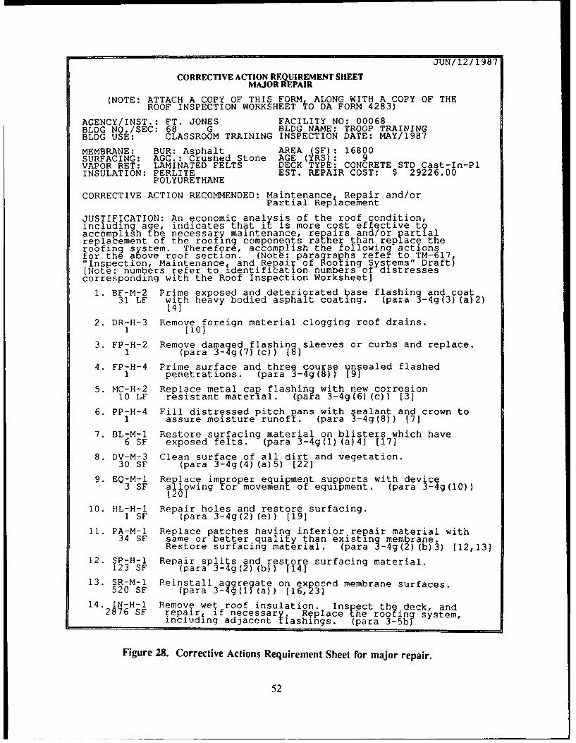
JUN/12/1987
CORRECTIVE ACTION REQUIREMENT SIIEETMAJOR REPAIR
(NOTE: ATTACH A COPY OF THIS FORM ALONG WITH A COPY OF THEROOF INSPECTION WORKSHEET TO DA FORM 4283)
AGENCY/INST.: FT. JONES FACILITY NO: 00068BLDG NO./SEC: 68 G BLDG NAME: TROOP TRAININGBLDG USE: CLASSROOM TRAINING INSPECTION DATE: MAY/1987
MEMBRANE: BUR: Asphalt AREA (SF): 16800SURFACING: AGG.: Crushed Stone AGE (YRS): 9VAPOR RET: LAMINATED FELTS DECK TYPE: CONCRETE STD Cast-In-PlINSULATION: PERLITE EST. REPAIR COST: $ 29226.00
POLYURETHANE
CORRECTIVE ACTION RECOMMENDED: Maintenance Repair and/orPartial Replacement
JUSTIFICATION: An economic analysis of the roof condition,including a e, indicates that it is more cost effective toaccomplish ?he necessary maintenance, repairs and/or partialreplacement of the roofing components rather than replace theroofing system. Therefore, accomplish the following actionsfor the a ove roof section. (Note: paragraphs refer to TM-617"Inspection, Maintenance, and Repair of Rooting Systems" Draft)(Note: numbers refer to identification numbers of distressescorresponding with the Roof Inspection Worksheet]
1. BF-M-2 Prime exposed and deteriorated 1ase flashing and coat31 LF with heavy bodied asphalt coating. (para 3-4g(3) (a)2)
[4]
2. DR-H-3 Remove foreign material clogging roof drains.1 (10)
3. FP-H-2 Remove damaged flashing sleeves or curbs and replace.1 (para 3- g(7) (c)) [8]
4. FP-H-4 Prime surface and three course unsealed flashed1 penetrations. (para 3-4g(8)) [9]
5. MC-H-2 Replace metal cap flashing with new corrosion10 LF resistant material. (para 3-4g(6) (c)) [3]
6. PP-H-4 Fill distressed pitch pans with sealant and crown to1 assure moisture runoff. (para 3-4g(8)) [7]
7. BL-M-l Restore surfacing material on blisters which have6 SF exposed felts. (para 3-4g(1) (a)4) [17]
8. DV-M-3 Clean surface of all dirt and vegetation.30 SF (para 3-4g(4) (a)5) [22]
9. EQ-M-l Re place improper equipment supports with device3 SF allowing tor movement of equipment. (para 3-4g(10))
(20]
10. HL-H-l Repair holes and restore surfacing.1 SF (para 3-4g(2) (e)) [19]
11. PA-M-l Replace patches having inferior repair material with34 SF same or better quality than existing membrane.
Restore surfacing material. (para 3-4g(2) (b)3) (12,13]
12. SP-H-l Repair splits and restore surfacing material.123 SF (para 3-4g(2) (b)) (14]
13. SR-M-l Reinstall aggregate on exposed membrane surfaces.520 SF (para 3-4g(1 (a)) [16,23]
14. IN-H-l Removq we roof insulation. Inspect the deck, and2876 SF repair, if necessary. Replace the roofin? system,including adjacent flashings. (para 3-5b[
Figure 28. Corrective Actions Requirement Sheet for major repair.
52

JUN/12/1987
CORRECTIVE ACTION REQUIREMENT SIIEETROOF REPLACEMENT
(NOTE: ATTACH A COPY OF THIS FORM ALONG WITH A COPY OF THEROOF INSPECTION WORKSHEET TO DA FORM 4283)
AGENCY/INST.: FT. JONES FACILITY NO: 00068BLDG NO./SEC: 68 G BLDG NAME: TROOP TRAININGBLDG USE: CLASSROOM TRAINING INSPECTION DATE: MAY/1987
MEMBRANE: BUR: Asphalt AREA (SF): 16800SURFACING: AGG.: Crushed Stone AGE (YRS): 9VAPOR RET: LAMINATED FELTS DECK TYPE: CONCRETE STD Cast-In-PlINSULATION: PERLITE EST. REPLACE COST: $ 88200.00
POLYURETHANE
CORRECTIVE ACTION RECOMMENDED: Total replacement of roof in 1987
JUSTIFICATION: An economic analysis of the roof condition,including age, indicates that it is more cost effective tototally replace the roofing system rather than perform thenecessary maintenance, repair, and/or partial replacement ofthe roofing system.
DESIGN CONSIDERATIONS: The following considerations should beaddressed during the design and con,;truction phases of thereplacement system:
a. Type replacement systems could includeI) bituminous built-up membrane2) sinle-ply membrane, such as EPDM, PVC etc.. IF a
ballasted system is selected, determine if thestructural components can sustain the added weight(approx. 10 lbs/SF).
b. Ensure tha the roof has positive drainage slope of atleast 1/4 inch per foot. Correct all areas that nowcontain ponded water.
c. Remove all unnecessary roof mounted equipment.
d. Inspic and repair or replace, as necessary, allremaining roof mounted equipment.
e. Ensure that all roof mounted equipment and penetrationsare properly installed on the roo1.
f. Until the replacement roof is installed, accomplishtemporary repairs to ensure that the roof remains leakfree.
Figure 29. Corrective Actions Requirement Sheet for replacement.
53

6 SUMMARY AND RECOMMENDATION
Summary
This report has presented ROOFER, an engineered management system for built-up roofs. Thesystem includes procedures for collecting and managing inventory information, visual inspection andcondition evaluation of the membrane and flashing, roof moisture detection and condition evaluationof the insulation, overall roof condition rating, and determination of MRR needs.
The overall roof condition rating procedure is based on the Roof Condition Index. The RCI iscomposed of three separate condition indexes for the membrane, flashing, and insulation (MCI, FCI,and ICI). These indexes have been field-validated and provide a means of establishing MRRrequirements and justification of roof projects. This report has presented ROOFER as a manual system,but as part of this work unit, USACERL has automated the system for a microcomputer application.The automated version improves data storage and retrieval, eliminates calculations, and provides customdesigned reports for management use.
Methods of Developing and Collecting Data
The development and collection of data for implementing and maintaining ROOFER at theinstallation can be accomplished by using one or a combination of the following methods:
e In-house resources, using permanent or a combination of permanent and temporary personnel,supported by USAEHSC.
9 Local A/E firm, suppored by USAEHSC.
9 Indefinite Delivery Type Contract (IDTC), managed by USAEHSC.
Methods of Accomplishing Nondestructive Roof Moisture Surveys
The nondestructive roof moisture surveys outlined in Chapter 4 can be accomplished through oneof the following methods:
local firms specializing in conducting rooftop surveys using IR scans or nuclear or capacitance
moisture meters.
* Aerial IR roof scans accomplished by:
- direct contract with a firm that specializes in aerial scans
- IDTC contract managed by USAEHSC
- USAEHSC directly.
Projcc't Mana, ement biar Implcmentation of Roofer
USAEIISC is responsihlc for providing assistance for implementing and maintaining the ROOFERprogriam at the installailion and MACOM level.
54
Recommendation
It is recommended that Army installations implement ROOFER. The system can be maintainedby in-house personnel or contracted to a qualified firm. Contract specifications for implementingROOFER are available from the Department of the Army, U.S. Army Engineering and Housing SupportCenter (ATrN: CEHSC-FB-S), Fort Belvoir, VA 22060-5580.
Conversion Factors
I sq ft = 0.093 m2
I in. = 2.54 cmI [t = 0.305 m
55

CITED REFERENCES
Shahin, M. Y., D. M. Bailey, and D. E. Brotherson, Membrane and Flashing Condition Indexes forBuilt-Up Roofs, Volume I/: Inspection and Distress Manual, Technical Report M-87/13 (U. S.Army Construction Engineering Research Laboratory [USACERLI, September 1987).
Tobiasson, W., and Korhonen, C., Roof Moisture Surveys: Yesterday, Today and Tomorrow, CRRELMiscellaneous Paper 2040 (U.S. Army Cold Regions Research and Engineering Laboratory[CRREL], September 1985).
Tobiasson, W., Aerial Roof Moisture Surveys, CRREL Miscellaneous Paper 2022 (August 1985);
Tobiasson, W., A Method for Conducting Airborn Infrared RooJ Moisture Surveys, CRRELMiscellaneous Paper 2436 (CRREI., April 1988).
Technical Manual (TM) 5-617, Facilities Engineering Maintenance and Repair of Roofs (Departmentof the Army, January 1974).
UNCITED REFERENCES
Air Force Manual (AFM) 91-36, Built-Up Roof Management Program (U. S. Air Force, 3 September1980).
Griffin, C. W. Manual of Built-Up Roof Systems, 2nd Edition (McGraw Hill Book Company, 1982).
Kncha-.s, A., S. Bunch, and J. Mose, Roofing Systems Analysis, Brochure (U.S. Army FacilitiesEr ginccring Support Agcncy, December 1985).
Shiahin, M. Y., M. I. Dartcr, and S. 1). Kohn, Development of Pavement Maintenance and ManagementSystem, Volume i: Airfield Pavement Condition Rating, Technical Report No. AFCEC-TR-76-27(U.S. Air Force Civil Engincering Center, November 1976), pp 32, 37.
Shahin. M. Y. and S. D. Kohn, Pavement Maintenance Management for Roads and Parking Lots,Tcchnical Report M-294 (USACERL, October 1981).
56

APPENDIX A:
BLANK WORKSHEETS*
BUIL~DING IDENIFICATION AGENCY/INST. NO.: IDATE--/ -/ - FA;ENCY/INST.:
BUillDING NAME:
BUILDING NUMBER: IDESIGN CATEGORY CODE II
US:YEAR BUILT: ______
ROOF SEC I IONS:
A rF _ SF K _______SF
B sF SF L ________SF
C sr H -'F MSF
D) _SF _ ___ SF N _ SF
E ________SF J _______SF 0 ________SF
R EMIARKS5:
BUILDING ROOF PLAN SCALE:
*Tlhesc formis have been slighily reduced.
57

AGENCY/INST.:
ROOF SECTION IDENTIFICATION
DATE: / BLDG NO: SECTION ID: AREA: SF
OCCUPANCY: YEAR ORIG CONST: YEAR LAST REPLACED:
10GENERAL
11 PERIMETER: 12 ACCESS:
PARAPET LF AREA DIVIDER LFROOF EDGE _ LF ADJ. WALL LFEXP. JOINT _ LF OTHER LF
20 STRUCTURAL FRAME
21 TYPE:
30 ROOF DECK
31 TYPE:
32 DESIGN LOAD: 33 SLOPE: 34 DRAINAGE:
LIVE PSF IN 12DEAD - PSF
40 VAPOR RETARDER
41 TYPE:
SO INSULATION
51 TYPE:
52 PHYSICAL PROPERTOES: E3 R-VALUE:BOARD STOCK FILLS
THICKNESS (in.) 54 ATTACHMENT:NO. OF LAYERSTAPERED
60 MEMBRANE
61 PRODUCT: PROTECTED MEMBRANE _ (Y/N)
MANUFACTURER DESCRIPTIONSPECIFCATION NO. WARRANTY (/NI
EXP. DATE
62 TYPE: 63 ATTACHMENT: 64 REINFORCEMENT:
65 SURFACING: 66 WALKWAYS:
70 FLASHING ,_
71 BASE FLASHING: 72 FLASHING ADHESIVE: 73 COUNTERFLASHING:
74 FLASHING TYPES:
80 REMARKS:
58
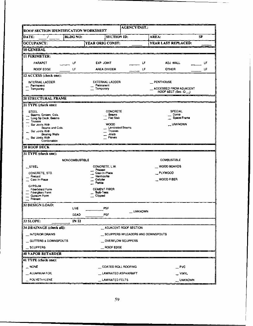
AGENCY/INST.:
ROOF SECTION IDENTIFICATION WORKSHEET
DATE: / BLDG NO: ISECTION ID: AREA: SF
OCCUPANCY: YEAR ORIG CONST: YEAR LAST REPLACED:
i GENERAL
11 PERIMETER:
PARAPET LF EXP. JOINT LF ADJ. WALL LF
ROOF EDGE LF AREA DIVIDER LF OTHER LF
12 ACCESS (check one):
INTERNAL LADDER EXTERNAL LADDER _ PENTHOUSEPermanent __ PermanentTemporary Temporary __ ACCESSED FROM ADJACENT
ROOF SECT (Sec. ID .
20 STRUCTURAL FRAME
21 TYPE (check one):
STEEL CONCRETE SPECIALBeams, Girders, Cols. __ Beams _ DomeLong Sp Deck, Beams _ Flat Slab - Space FrameTrussesBar Joists With WOOD __ UNKNOWN
Beams and Cols. Laminated BeamsBar Joists With Trusses
Beanng Walls _ JoistsBar Joists With Panels
Combination
L30 ROOF DECK31 TYPE (check one)':
NONCOMBUSTIBLE COMBUSTIBLE
-STEEL CONCRETE. LW. WOOD BOARDSPrecast
CONCRETE, STD. _ Cast-In-Place PLYWOODPrecast __ VermiculiteCast-In-Place __ Cellular WOOD FIBER
PediteGYPSUM
Fiberboard Form CEMENT FIBER- Fiberglass Form _ Bulb-Tees
Gypsum Form _ ClippedPrecast
32 DESIGN LOAD:LIVE PSF
UNKNOWNDEAD PSF
33 SLOPE: IN 12
34 DRAINAGE (check all): _ ADJACENT ROOF SECTION
__ INTERIOR DRAINS __ SCUPPERS W/LEADERS AND DOWNSPOUTS
- GUTTERS & DOWNSPOUTS __ OVERFLOW SCUPPERS
_ SCUPPERS ROOF EDGE
40 VAPOR RE ]TARDER
41 TYPE (check one):
__ NONE -COATED ROLL ROOFING PVC
__ ALUMINUM FOIL __ LAMINATED ASPH/KRAFT VINYL
_ POLYETHYLENE _ LAMINATED FELTS UNKNOWN
59

50 INSULATION
S1 TYPE (check all): - EXTRUDED POLYSTY. INSULATING FILLSNN Vermiculite
NN -N FOAMGLASS __ PediteWO Cellular
_WOOD FIBERBOARD PHENOUC - GypsumGA Lwt Concrete
_ GLASS FIBER- POLYISOCYANURATE - Fill Type Unknown
_ PERUTE - CORK __ UNKNOWN
_ POLYURETHANE/BOARD -FOAMED IN PLACE/PUF
_ EXPANDED POLYSTY.
52 PHYSICAL PROPERTIES: _ N/A (No Insul.)
BOARD STOCK FOAMED IN PLACE AND INS. FILLS
TOTAL THICKNESS INCHES TOTAL THICKNESS INCHES
NO. OF LAYERS TAPERED (Y/N)
TAPERED (Y/N)
53 R-VALUE (total): UNKNOWN __ N/A (No Insul.)
54 ATTACHMENT (board stock only)(check all):
__ MECHANICAL -ADHESIVE-HOT __ UNKNOWN
_ LOOSE LAID -ADHESIVE-COLD
60 MEMBRANE
61 PRODUCT: _ UNKNOWN PROTECTED MEMBRANE - (Y/N)
MANUFACTURER DESCRIPTION
SPECIFICATION NO. WARRANTY _ (Y/N) EXP DATE
62 TYPE (check one): ROLL ROOFING UQUID APPUED- OrgJMin. Surface - Neoprene/Hypalon
BIT. BUILT-UP Glass/Min. Surface - Acrylic Elastomer_ Asphalt - Smooth - Butyl
_ Coal Tar Pitch - Polysulfide_ Cold Process\ SINGLE-PLY __ Urethane
Emulsion EPDM Silicone_ Cold Process% - CPE Type Unknown
Cutback CSPE- Bit Type Unknown - PIB PUF WITH COATING
PVC SiliconeMODIFIED BITUMEN - Butyl _ Urethane
_ SBS - Neoprene _ Catal. Urethane_ APP - Nitile Acrylic
Modifier Unknown - Type Unknown Coaling Unknown
63 ATTACHMENT (for Singie-Ply only)(check one):
__ FULLY ADHERED - PLATE/DISK/PARTIALLY ADHERED
_ LOOSE/BALLASTED MECH. FASTENERS- Penetrating- NonPenetrating
64 REINFORCEMENT (check one): MODIFIED BITUMEN & SINGLE-PLY- Polyester, Woven
BIT BUILT-UP - Polyester, Nonwoven__ Organic Felt - Glass_ Glass Felt Asbestos_ Asbestos Felt Fleece, Synthetic__ Felt Type Unknown Felt
Laminate BackerPolyethyleneReinforcement UnknownNo Reinforcement
60

65 SURFACING (check one):
AGGREGATE SMOOTH __ MINERAL SURF. CAPRiver Gravel __ CutbacCrushed Stone __ Emulsion _ LATEX COATINGSlag __ Hot AsphaltPea Gravel __ Sit. Type Unknown PAVERSVolcanic Rock __ ConcreteMarble Chip __ REFLECTIVE - CompositeLimestone
__ Aluminum Granule _ ELASTOMERIC OTHERMineral GranuleAgg. Unknown __ METAL SKIN NONE
66 WALKWAYS (check all): _ RUBBER MAT
-ASPHALT PLANK _ WOOD DUCK BOARDS _ OTHER
-CONCRETE PAVERS - MINERAL SURFACED FELTS _ NONE
170 FLASHING
71 BASE FLASHING (check all):
MINERAL SURFACED MODIFIED BITUMEN __ PVC COVERED METALOrganic Granule SurfaceGlass Foil Surface __ METALFabric Unknown Smooth Surface~CPE
RE!NFORCED ASBESTOS VINYL-- __OSPE
FIBERGLASS PVC-- __NONE
COTTON NEOPRENEUNKNOWN
BURLAP EPDM
72 FLASHING ADHESIVE (check one):
-HOT MOPPED __ TORCH APPLIED
COLD MASTIC UNKNOWN
73 COUNTERFLASHING (check all):
METAL __ FLEXIBLE
BITUMINOUS - NONE
74 FLASHING TYPES (check all):
ROOF EDGE __ ROOF PENETRATION __ PITCH PAN_ Embedded Edge Met
Metal Cap Flash. __ ROOF RELIEF VENT PIPE SUPPORTSWood Blocks
_WALUPARAPET __ PLUMBING VENT Rollers
-COPING EQUIPMENT SUPPORTStructural Frame
_AREA DIVIDER _ CurbsConduit
EXPANSION JOINT _ Wood SleepersMetal Cover __ None (unflashed)
_ Flexible Cover
80 REMARKS
61

ROOF INSPECTION WORKSHEET 1 AECI
BUILDING ___PER. FLASHING LF DATE ______
SECTION _____ CURB FLASHING LI' NAME ______
SF-B3ASE FLASH PP-PITCH PANS SP-SPLITS PA-PATCHING I D S D0QMC-METAL CAP DR-ORAIN & SC HL-HOLES Dy-DEBRIS & VEG 0 1 E E TEM-EM13EDD MET BL-SLISTERS SR-SURF DET EQ-EQ SUPPORT S V F VFP-FLASHED PEN RG-RIDGES SL-SLIPPAGE PD-PONDING
SCALE:________NORTH
62

ROOF INSPECTION WORKSHEET - COMMENTS
INSTRUCTIONS: Circle response, i.e., Y = yes, N = no or U = unknown ornot observed. If Y (yes), circle the type of problem.
A. EVALUATION OF INTERIOR CONDITIONS
1. Does the roof leak? Describe: Y N U
2. Are there water stains on: Y N Ua. walls c. deck e. structural elementsb. ceilings u. floor t. other:
3. Do structural e]nents zno', any of The 'Ilowing: Y N Ua. cracks d. a terati n g. physical damageb. splits e. rott.r:4 h. insect damagec. spal i . e:, e:r, n i. other:
4. Does the undersie uf the deck show any of the following: Y N Ua. rustrn: 2. spa>i n j e. sagging
o tng 1. 'rac:s C. other
B. EVALUATION OF EXTERIOR CONDITIONS
I. Do the e'tro walls shown any oz the following: Y Na. cracks c. spalling e. water stainsb. rusting d. movement f. other:
2. Does the fascia or soffit show any of the following: Y Na. cracks c. spalling e. water stainsb. rusting d. peeling f. other:
3. Do the gutters or downspouts snow any of the following: Y Na. loose c. missing e. cloggedb. damaged (. disconnect f. other:
C. EVALUATION OF ROOFl)0P CONDITIONS
I. Is there any unauthorized, unnecessary, or improperly Y Ninstalled eqi jpm,?nt -,n the roof?a. equi pm- nt c. antennas e. cablesb. signs d. platforms f. other:
2. Do adjacent parapet wal]ls show any of the following: Y Na. cracks c. cap cracked e. sealantb. spailing d. cap missing f. other:_
D. REMARKS:
o.;

ROOF SECTION RATING FORMBUllDIN(G SECT ION DAl F CALC. BY
PER. FLASHING Fr FLASIIING CIIKD. BYCURB HFIASIIING FT OTAL F' AREA SQFl'
FLASIIlNG MEMBRANE
DISTRESS TYPES DISTRESS TYPESBF BASE FLASH DR DRAIN & BL- BLISTERS SL - SLIPPAGEMC METAL CAP SCUPPER PG - RIDGES PA - PATCHINGEM- EMBEDDED MET SP - SPLITS DV - DEBRIS & VEGFP - FLASHED PEN HL-HOLES EQ - EQU SUPPORTSPP -FPiCH PANS SR - SURF DET PD - PONDING
TYP SV QUANTITIES TOT DEN DV TYP SV QUANTITIES TOT DEN DV
('ORRF(-I Fl) IPFDICT VALUE (CIV) CORRECTED DEDUCT VALUE (('DV)
= -0 ('IV M I = 100 - CDV =
F.ASIIl(; RAI IN(G -- MEMBRANE RATING _
6-4

AGENCYIINST.:
ICI CALCULATION SHEET
DATE: / / BLDG. NO.: SECTION: AREA: SF
MC CALC. BY: I 1SF & ICI CALC. BY:
1. DETERMINATION OF MOISTURE CONTENT AND INDIVIDUAL ISF OF CORE SAMPLES
A B C D E F %WATERCORE INSULATION THICK TARE WET+ DRY+ WET DRY WATER (FIE) ISF
TYPE WT TARE TARE (B-A) (C-A) (D-E) X 100
2. DETERMINATION OF AVERAGE ISF 3. DETERMINATION OF ICI
CORE ISF WET AREA (A) X (B) PROBLEM DENSITY:(A) (B) (TOTAL WET AREA I TOTAL AREA) X 100
IDV:
WAF:
ICI:
100- [(IDV + WAF) X AVERAGE ISF I
TOTALS (C) (D)
AVERAGE ISF (DV(C) RATING:
1. DETERMINE THE ISF FOR EACH COMPONENT OF COMPOSITE INSULATION;FOR EACH CORE USE THE LARGEST iSF WHEN DETERMINING THE AVERAGE ISF.
2. DO NOT INCLUDE ANY AREAS THAT HAVE AN ISF OF ZERO
3. ROUND ICI TO NEAREST WHOLE NUMBER.
WET AREA FACTOR (WAF 11 INSULATION CONDITION RATING
WET AREAS WAF ICI
1 0 86 100 EXCELLENT
2 4 71 85 VERY GOOD
3 6 56 70 GOOD
4 8 41 55 FAIR
5 OR MORE 10 26 40 POOR
11 25 VERY POOR
0 10 FAILED
65

I AGENCY/INST.:RCI CALCULATION SHEET
DATE: /_/_ BLDG NO: I SECTION ID: ]AREA: SF
ROOF SECTION WITH INSULATION:
VALUE LOWEST OTHER
TOTAL
X0.70 X0.15
(A) (B)
(A B)
RCI
RATING:
ROOF SECTION WITHOUT INSULATION:
VALUE LOWEST OTHER
TOTAL
X 0.70 X 0.30
(A) (B)
(A+B)
RCI
RATING:
MRR RECOMMENDATIONS
86 100 ROUTINE MAINTENANCE
71 85 MINOR REPAIRS NEEDED
56 70 MODERATE REPAIRS NEEDED
41 56 MAJOR REPAIRS NEEDED
26 40 REPLACEMENT PROBABLE
11 25 REPLACEMENT NEEDED
0 10 REPLACEMENT CRITICAL
6

APPENDIX B:
TEST "ro I)E'rERMINE 111ITIMEN TYPE
1. Obtain a small specimen of the roofing bitumen from the top pouring. The sample should be as
clean as possible with uncontaminated surfaces exposed.
2. Place sample in a glass jar containing mineral spirits, gasoline or other petroleum based solvent.
3. Mix or shake the jar for bout 20 seconds.
-4. If tie solvent turns black or is not transparent, the bitumen is asphalt.
5. 11 the solvent turns yellow or yellow-green, the bitumen is coal-tar pitch.
6. Tcst [clt samples in a similar manner using several small torn pieces of felt.
67

APPENDIX C:
DEDUCT VALUE CURVES
BASE FLASHING (BF) FLASHING100 -- - -
90-H
11 7 0 -
630-
0
20-
10-0 -
DISTRESS DENSITY - PERCENT
10METAL CAP FLASHING (MC) FLASHING
90-
w 60
50_
40
DITRS DESTH ECNw 60

EMBEDDED EDGE METAL (EM) FLASHING100-mm
90 - ------ H
1&70...--60- - m
50 flU -0
20.
DISTRESS DENSITY - PERCENT
FLASHED PENETRATIONS (FP) FLASHING100 - - --- --- --
80 - -- ----
5 70 - - -- --
5 0 TLH
o30 or
2o M
0.O
DISTRESS DENSITY-PERCENT

PITCH PANS (PP) FLASHINGI00 -
w_S70
- r
a30 A,
20 . ... L,
1 0 mom!!.p.
50 wag=_
0.01 0.05 0. 0.5 1 5 10DISTRESS DENSITY-PERCENT
INTERIOR DRAINS ANDROOF LEVEL SCUPPERS (DR) FLASHING100
so70 1+-___
-50 -
D40 H
.. __0 _07
I0 ,
0.01 0.05 0.1 0.5 1.0
DISTRESS DENSITY-PERCENT
70

- - - E
cn.
000
0OD C~H
(AGO)~~ ~ ~ ~ 3n:2ioG003080781

1BLISTERS (BL) MEMBRANE
960
00
50
100 -400 -
00
10
0.01 05 10~ 50 100
DISTRESS DENSITY - PERCENT
702

SPLITS (SP) MEMBRANE
100 IfIm I II -
8O - 1 1 fi l I-I I
740 _l
0430
300.001 0 .0000 1
DISTRESS DENSITY - PERCENT
HOLES (HL) MEMBRANE
90-- :" -- I H80--
~70 - -
~60
0
o40_o30
20 F__
l00.001 -0650.061 .050.5 10
DISTRESS DENSITY-PERCENT
73

SURFACE DETERIORATION (SR) MEMBRANE100 Hil m - -
90~ -- Hill H
30 -il I
S40-30-201 -L
10-0 ~
0.01 65 01 5 1 5 10 50 100DISTRESS DENSITY - PERCENT
1SLIPPAGE (SL) MEMBRANE
90 -
W7 0 -
30
DISTRESS DENSITY - PERCENT
74

PATCHING (PA) MEMBRANE
90- -v111
460
~40 - - L0T
0 _0
10
I0
0.01 05 0.1 5 10 50 10
DISTRESS DENSITY - PERCENT
DEBRIS AND VEGETATION (DV) MEMBRANE
90--- H
- M00
40-0 -!-
20-
10-
0.01 05 615 15 1 o
DISTRESS DENSITY - PERCENT
75

IMPROPEREQUIPMENT SUPPORTS (EQ) MEMBRANE
90 --- 11
6-0~I- T__
IJJT
o30 A12000f10
0.0
DISTRESS DENSITY-PERCENT
1PONDING (PD) MEMBRANE
90-- -
w70- L
S60-~50-
ria -- -r
10 1-f
of IF Nan
0.0105 15 1050 100
DISTRESS DENSITY -PERCENT
76
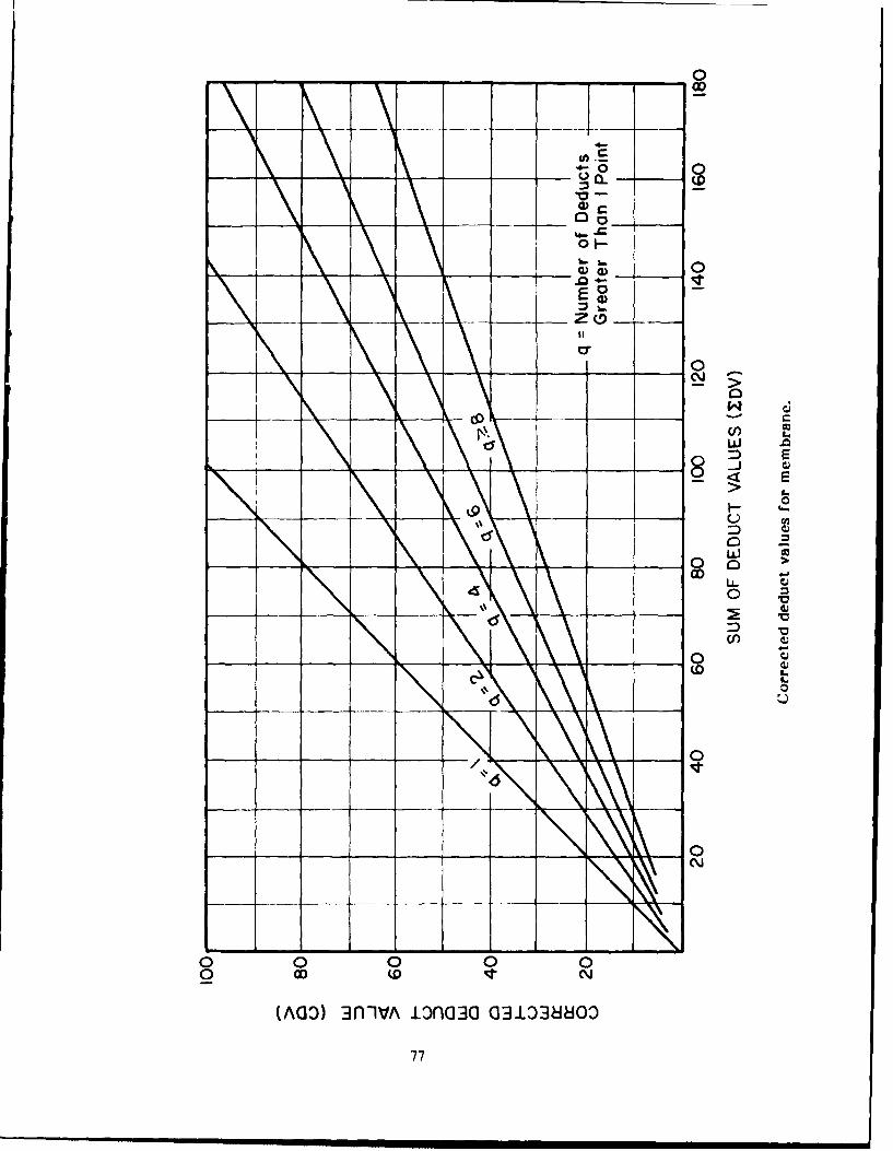
0
OD
E00
0J 0
w >U-
0
O N
(A ) L
770
\\\\\\4
O O O O0O cO 1" o,
(ACI) :1n "IA .L:3F (] lC! 3:1 LD ( IO
770
- ,,- ,,. mmmmmmmm uml inm ll IB m • m n n um m'm

USACERL DISTRIBUTION
hcid ,I Flgecrs FORSCOM Tyndall ANI', I-. 32403ATI N (:IM-SI, (2) FORSCOM Engineer, AT'FN: Spt Det. AFESC/Enginecring & Service LabA'ITN: Ci'CC-P ATI'N; Facilities Enginecr (27)ATIN: CI"CW NAVFACA'IIN: C('IW-O IISC ATTN: Division Offices (11)AIl N: CFCW-P Ft. Sam llouston AMC 78234 AITN: Facilities Fngr Cmd (9)AT1I N: CECW RR ATI'N: IISLO-F ATI'N: Naval Public Works (:r (Q)AI'-N" CFM' U itzsimons AMC 80(45 AITN: Naval Civil Engr Lab (3)ATIN ('EMP-C A'Il'N: IISIIG-DI:I ATTN: Naval Constr Batalion CtrAI'IN (EMP-I F Walter Reed AM( 20307
I\ N (T RD A'ITN: Facihtim Engineer Engineering Societies L.ibraryI'IN (IRD-I New York, NY 10017II N (T RI)( INSCOM - Ch, Instl. Div.
,\I N ('FRD M Arlington lall Station (4) 22212 National Guard Bureau 20310A IIN CI :RM A*I'N: Facilities Enginccr Installation DivisionAI'IN l)AIN -ZCI Vint lhll [arms Station 22186"ITN: )AFN-ZCI A'IN: IAV-DI'II US Government Printing Office 22304
N: l)AEN-/CM Receiving/Depository Section (2)A IN )A N-ZCZ USA AMCCOM 61299
AIN: AMSMC-RI US Army Env. Hygiene AgencyI 5' AI'IN CI-IISC-/C 220(g) ATIN: AMSMC-IS A1TN: IISIB-ME 21010
AlIlN 1)1- III 79906Al IN. Ci-IISC-F 22060 Military I)tst of Washington Nat'l Institute of Standards & Tech 2t)9'o
I'I N: ('EISC-TF 22060 ATIN: DlilI" II N Canadian Iiaison Oificer 65473 Cameron Station (3) 22314 Defense Technical Info. Center 22314.,VITN: German L.iaion Staff 65473 Fort Laesley J McNair 20319 A'ITrN: DDA (2)Al' N. French Liaison Office, 65473 iort Myer 22211ATI N Water Rc-sources C'cnlr 22060 321
Military l'raffic Mgmi Command 12/891 S An:;, l.ipncer I)istricts Falls Churih 20315
A I'I N: L hrary (4I) Oakland Army Ilase 94626Iliyonne 07(X)2
I S 'Nn, I K): sons Sunny Point MO'T' 28461A IN \ I.iJrarv ,14)
NARADCOM, AT'N: DRDNA-I 01760I S Arnn Europe(Il)('S/Ingtiner 1194113 'ARCOM, Fac, I)v 48090
AlI N AEA N FIEA'I N AIFAIN "IRAIDXO
V (,,ir'. IQ. 'TRADCX, ATI'N: ATI'EN-D'II 21 651A IN )111 l !) ATIIN: DEII (18)
\I IT C'psA1I N D1)11 (16 TSARCOM, ATrN: STSAS.F 63120
1q Smtpor ('ornmardAlIN DIHI (12) IUSAIS
15A lirthn in Iluachuca 65613A'1N DNlEI (4) AlI'N: Facilities Engineer (3)
XI l t' r,mmanl l:iroe (ACE) Fort Ritchie 21719AYI N A('S(Ili (l 9(11AlIl N SllIIll/1Engincr (1W155 WESTCOMA 11N AIUEiS 1M081 IEor Shafter 96858
SS;ASIIAEI AI IN: DHIlA'l'N AlISi EN I) 101(019 ATIN: API'N-A
I:h l..A. Korra (19) SIIAPI 091.55
A'IIN: Survivability Sect ('C'Cl-OPSRI K,' (' iihtnc ! [Im-ci Ci 46301 A IN: lnfrastructure Branch, IANIA
A I'] N II S1A I 1' (1/liivgrII0 I'SITiCOM (1128
I'S I t ii S\KIh A'IIN, l:(| 4 ' lOAI I\ D111 N ,)(,LIA I' ' N 1! .'iti. I-ngr I lonmli 9634; Fori Ilclvii, VA 2200,0SI-I N )111 Ok;laVa qt,13l A l'lN lirnih liaison Officer
A ITN: Australian liaison Officer"5I'a liii'dir, All 11' Arca tIhc Al IN IFngr Studites CenterXr,,,( M:t I, ,, St.~ui~ n IN • s0 AI'l N I1ngr lopograplic lab
AI'IN A[/A II SW
SLIN I.ii,i' I'1 'iccr A'IN II(CC R
S A dvl,:.,- A ,,'r 101966 I'( RI All N library 0)1755A J'I N I'a 11:i l:ngin.cirA. I I I i" 1),,t't4 % WES. A'I'l N: I ihrary 3910
"mpuern\I1 IN \ \lXFN A IIQ, XVIII Airbinic ('irps and
Fi Ilrigg 2117'i'l' );r, Int . & Sv(s Al'IN AI'/A.III Il-+
A.'I\ 1)11 (1)Chaniti AlII, 11. 61868
1)l .\ 'I N )IT WI 2?21) 314 ('11-/ E, Stp 27
IDNA A I-I N NAI)S 211111 Noton AFI, CA 1024(nAI'IN AFIRCE MX/l)F

EMC Team Distribution
Chii of ingcni 0314Earlast9630 Vt. Ilenning, GA 319015A~~a Has 9630 (1 8 0 /AA I : C II)1, N: AT'/,1-DI II-IIG
A, 1*I N ( FMI' /A M2 PIn (2( All N: ATZI3-IiI-F
Al IN. IIAIIN /T MTlN: ( ;ciitnh 1ngr BrFt zvnohK 602ATIN: ('hiv, FM-IF ~avnoh K 62
CH IsC A IN: Chier FN-I3H-ST AInIN: ATZLCA-SA
Al-IN: CHIISC-FII-S Seattle 9S124 Frt. Lee, VA 23901
A]IN: (l:II SC-illB-I IN: (,idu, NPSCO A IN: A.MMC-D (2)ATI : CH ISCFBAiM: (:hief, NI'SIN-l.M
I'S Army Engincer D~istrict AT'N: 'I lief, 1:N-lNAM ST Ft. McPherson, GA 30330
NyuYor 1078Walla Walla 99362 A'ITN: AFTIN-CI)~N : (York f Desin h AYIlN: (Iiief, Iingr Div
Thrbrh15222 Alaska ()9506 F.MnoV 35
AXITN: (Thicf. ORPCI3 A'1I1N: NPAEiN-G-M AKIrN: AThN-AD
A 1-IN: Chbief, Engr Div ATT'N: ATEN-FN (2)
I'I: 'Ile~phia 191M( US Army Engineer Division lN AE-N(2
\fjIN 'hicfNAI'1 New England 012154
I.pv21M-1i ATON hif EDI- Ft. Richardson, AK 99505
XIAN I I, I or Div At'I*N: Laboratory ATMN: AFVR-DE-.E
N,, k 2'W l AnI N: Chicf. NlA:)
XiI N: hit I, N VAIIN \1 Nornth Atlantic i() Rocky MJou.ntaini Arseil. 80022
Al 1I N.Ei N VI IN 1) ATlN: (p.NADIINI MTlN: SARRM-CO-FEP
l 2S7 ri ~01 MJIdwle East (Rear) 2?6(1
I-I 0-! ()KRill1) G, IN: (Thief, MIII)E13-( ISAWiES 39180South Atlantic AYI[N: CISt'ruciure
SAl N% - N D AT]. NI N: ILahoraiomy 3001601 AKIN: Soils & Pavements I ab
i ,ir 't'ATI"N: Chfilef. SAIN-rC 10303 aa c;,esEgComn 232
\IAN Ch,,:!, I ogr I)lv AITN: Chief, SAI)IN-'IS M3ul3NvlacesEg omn 237
'is n . II ~ Huntsville 358117 AMlN: Code 2003
AI-IN 0! I,1 S S L55I AnIIN: Chief. I INDliI)CSI AnrN: Chief, hINDlEhl-M (X3MMANDFR ((:031 2636) ql35 5
I IN (-.l)irh AIIN: Chief, IINIDLDI-SR Nasal Weapons Center'
1(4 2Lower Mississippi 3918W
Xli N(05 SAMINI)AflN Chief. LMVFDI-G Little Rck AFB 72(K)9
All" N Chlejf, SXMFN 1; Ohio River AN 14DII
AFIN C ('pit SA,\III.N-C ATnN: ILah-oratory 45227 Bidn aac or 01
372112 A'iTN Chief. Engr Div 45201 IuligRsac ladCi
A FIN: C hief, (RN III)P Missouri River
'skmpls 38103 AIlN: Chief, MRDED 3 68101 D~ept of'rransportation Library 205)O
IN (S f ntr Dv MTN: Lalsra'ory 68102AIN: Chief, Cnir .II Iv Souhwestemn 75202 Tiransportation Research Board 2041S
Si burg 31ii,A)I ATnN: Laboratory
AIN: ( '- Igr 1)' KYN: Chief. SVWDI:3-\IA
40,041 pA AITN: (Thief, SWI I -G 0
1-IN- (ivxl I gr Iv South Pacific 94906 +10KI, X21AiN: ILaborawory 9-
\IN Ci Ni" \(> I) IPacific Oxean 96858'./8
I N I,' 1:1)1) ATIN: F%1,1S Branich
XIN I( NiSI )(;11l Ml IN: P'OI))Nool Picific
IN ( NI -I, GU AlN: Miterials1 Ll (i
N Ip' 1 0MT~N: Cief. Engr IDiv '7 2 0 X
Is I i 61 IP(,71h US Amy (94017
AI NV I im-ii I gr DIv IN: All IlM-IXII-MG-_II
II (ppp nrD"p I IQ, ('i inbinel ]I in1. Arm %ty (OK/I s)
\cis 'n (li Ai'T, IN: CIXR-IIN 9635h
* 'PP E~~S Anny Forsiigrr Sci&TcCr
I IN ! v g, D): All IN: Charlouesville. VA 22901
I .'All IN Far Fast (1(11c 96328
Ii tX \\wh 76 '. U~SA ARRADCOM 0p71((1
Al I-N (*),;,I, MYTH) 3) ATfN: I3RIAR-I.CA-0K
Al N, ('1jri SV WGA 1,I1 77553 IIQ. IISAMRI3C' 2171
\1-IN ChI, f. %WGCII C 77553 kilN: SGRI)-ILCA I IN ( iI, SV. OIJ) D)C 7755(1
A!P'.aiiirilv %,'7101 West Point, NY 101996
Il I N Ii! I ng, D:,p ATnN: lDept Of MeChaldn ic'
Are ,* Pi FIN III i.brary)
S., I ,,pnci' 91110i Ft liivipr, VA 220601
A I ( N Chipi I Igrr IDiv \I'IN I enirig H esni rcvs C(c ir
S.,i I.I'ti it Q I.l
All N (1 S'IJ)D ICI IN C SI k(I ,