rooft@ir - certus - inženierijas...
TRANSCRIPT

41 to 108 kW
Engineering Data Manual
AN AIRWELL GROUP COMPANY
43 to 108 kW
RoofT@irRooftop UnitsCooling Only and Heat Pump Versions
Models RTL/RTH 40 to 110
2
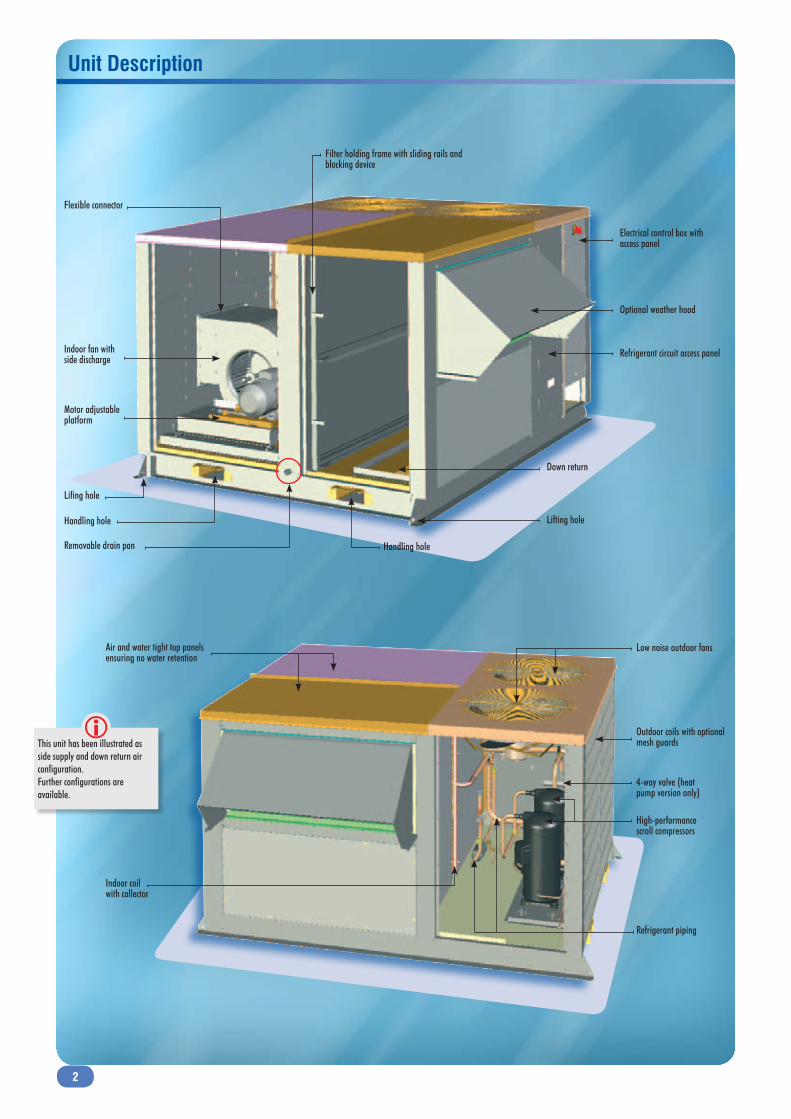
Unit Description
Filter holding frame with sliding rails and blocking device
Electrical control box with access panel
Refrigerant circuit access panel
Optional weather hood
Lifing hole
Flexible connector
Indoor fan withside discharge
Motor adjustableplatform
Removable drain pan
Down return
Handling hole
Handling hole
Lifting hole
Air and water tight top panels ensuring no water retention
Low noise outdoor fans
Outdoor coils with optionalmesh guards
High-performance scroll compressors
Refrigerant piping
Indoor coilwith collector
4-way valve (heat pump version only)
This unit has been illustrated as side supply and down return air configuration.Further configurations are available.
3
Technical Features
General Assembled weatherproof single package, using R410A refrigerant to
improve EER.
Fully insulated cabinet provides the best thermal and acoustical protection.
Cooling Only, Heat Pump with additional heating (optional) by electric heaters or hot water coil.
A full run test is performed at the factory before shipping to ease commissioning on site.
Cabinet Compact, light and single piece design.
All panels, floor and roof exposed to weather, are painted inside and outside to prevent corrosion.
No visible screws or bolts on the cabinet improve aesthetic and eliminate risk of punctuated corrosion.
All metal-to-metal contact surfaces exposed to the weather are sealed with closed cell neoprene gaskets.
Sloped roof to ease rain water drainage.
Removable service panels for full unit access.
Access panels are fastened by a quarter-turn rotor lock using a triangular handle.
Galvanized steel single base rail ensuring high structural rigidity.
Rigging holes and fork lift openings on the base rail to facilitate transportation and handling.
Optional roof mounting curb, factory assembled, non adjustable or adjustable to suit roof slopes.
Insulated with glass wool MO 62 kg/m3 – CE certified.
Air treatment compartment with 25 mm insulation to reduce energy loss (0.035 W/m.K), thermal bridge and sound disturbance.
Optional double wall design panels to prevent insulation fiber entering into the building and harmful build-up of bacteria or contaminants.
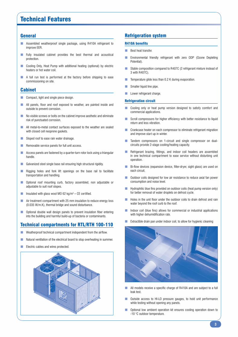
Technical compartments for RTL/RTH 100-110 Weatherproof technical compartment independent from the airflow.
Natural ventilation of the electrical board to stop overheating in summer.
Electric cables and wires protected.
Refrigeration system
R410A benefits
Best heat transfer.
Environmental friendly refrigerant with zero ODP (Ozone Depleting Potential).
Stable composition compared to R407C (2 refrigerant mixture instead of 3 with R407C).
Temperature glide less than 0.2 K during evaporation.
Smaller liquid line pipe.
Lower refrigerant charge.
Refrigeration circuit
Cooling only or heat pump version designed to satisfy comfort and commercial applications.
Scroll compressors for higher efficiency with better resistance to liquid return and less vibration.
Crankcase heater on each compressor to eliminate refrigerant migration and improve start up in winter.
Tandem compressors on 1-circuit and single compressor on dual-circuits provide 2-stage cooling/heating capacity.
Refrigerant brazing, fittings, and indoor coil headers are assembled in one technical compartment to ease service without disturbing unit operation.
Bi-flow devices (expansion device, filter-dryer, sight glass) are used on each circuit.
Outdoor coils designed for low air resistance to reduce axial fan power consumption and noise level.
Hydrophilic blue fins provided on outdoor coils (heat pump version only) for better removal of water droplets on defrost cycle.
Holes in the unit floor under the outdoor coils to drain defrost and rain water beyond the roof curb to the roof.
Indoor coil (blue fins) allows for commercial or industrial applications with higher dehumidification rate.
Extractible drain pan under indoor coil, to allow for hygienic cleaning
All models receive a specific charge of R410A and are subject to a full leak test.
Outside access to HI-LO pressure gauges, to hold unit performance while testing without opening any panels.
Optional low ambient operation kit ensures cooling operation down to -10 °C outdoor temperature.
4
Technical Features (continued)
Blowers and drives
Standard belt driven centrifugal dual inlet blower with forward curved
blades.
Optional centrifugal blower with backward curved blades for industrial
applications and higher external static pressure.
Single speed motors supplied with adjustable pulleys to fit operating
conditions on site.
Motors with permanently lubricated sleeve bearings to assure long
lasting operation.
Motor mounted on an independent platform with adjusting spanner
screw to ease alignment and belt tension.
Blower with flexible connection to eliminate vibration transfer to cabinet.
Factory fitted airflow switch (optional) located between entry and exit of
blower for correct control, wired to the controller (IATC).
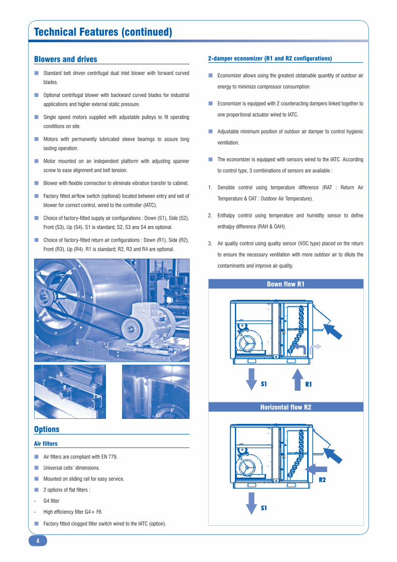
Choice of factory-fitted supply air configurations : Down (S1), Side (S2),
Front (S3), Up (S4). S1 is standard; S2, S3 ans S4 are optional.
Choice of factory-fitted return air configurations : Down (R1), Side (R2),
Front (R3), Up (R4). R1 is standard; R2, R3 and R4 are optional.
Options
Air filters
Air filters are compliant with EN 779.
Universal cells’ dimensions.
Mounted on sliding rail for easy service.
2 options of flat filters :
- G4 filter
- High efficiency filter G4+ F6
Factory fitted clogged filter switch wired to the IATC (option).
2-damper economizer (R1 and R2 configurations)
Economizer allows using the greatest obtainable quantity of outdoor air
energy to minimize compressor consumption.
Economizer is equipped with 2 counteracting dampers linked together to
one proportional actuator wired to IATC.
Adjustable minimum position of outdoor air damper to control hygienic
ventilation.
The economizer is equipped with sensors wired to the IATC. According
to control type, 3 combinations of sensors are available :
1. Sensible control using temperature difference (RAT : Return Air
Temperature & OAT : Outdoor Air Temperature).
2. Enthalpy control using temperature and humidity sensor to define
enthalpy difference (RAH & OAH).
3. Air quality control using quality sensor (VOC type) placed on the return
to ensure the necessary ventilation with more outdoor air to dilute the
contaminants and improve air quality.
Down flow R1
Horizontal flow R2

5
Technical Features (continued)
The economizer reduces the operational time of the compressors using outdoor air to satisfy the cooling or heating demand.
Outdoor air damper closed on OFF periods.
Outdoor air damper closed on start-up, morning warm-up and night-set-back modes for an economic operation.
The 2-damper configuration is suitable only for bottom or side return air configurations (R1 and R2).
A retractable rain hood with bird screen is factory-assembled.
Moisture eliminator on fresh air is optional.
Options of exhaust air on the economizer
Depression shutter (not compatible with R2)
Not compatible with the exhaust blower.
Exhaust air system with barometric damper to assist natural building de-pressurization when the return air damper is closed.
One-way depression shutter closed on OFF periods to avoid outdoor air intake.
Supplied with retractable rain hood to ease transportation.
Exhaust blower (not compatible with R2)
Exhaust air blower kit, for mechanical removal of used air from the building, when the ducted return air is designed at pressure drop higher than the building natural leakage rate.
Used when economizer is fitted on the unit. Activated by the control when fresh air damper is 100% open.
The blower exhausts up to 25% of the nominal air volume on closed return air damper.
Installed at 90° from the outdoor air intake to avoid air short-circuiting.
Manual 25% fresh air function
Factory fitted manual outdoor air system to ventilate the building with outdoor air up to 25% of nominal air volume.
Not compatible with the economizer.
Retractable rain hood to ease transportation.
Bird screen.
Non-return shutter closed during OFF periods, preventing infiltrations of
outdoor air.
Moisture eliminator is optional (factory-fitted or field-installed).
Hot water heating
Hot water heater available on all air flow configurations.
1 or 2 row coil mounted on a sliding rail and covers the entire surface of
the indoor DX coil. Advantages :
- Low air face velocity
- Low noise level
- Low pressure drop (approx. 10 Pa)
Located downstream of indoor DX coil.
Access hinged door with quater-turn fasteners to ease service.
3-way valve with copper plumbing and anti-freeze thermostat fitted at the
factory inside the unit.
Electric heat (S1 and S3 configurations)
Electric heaters available on down flow (S1) or front flow (S3) supply air
configuration.
The electric heaters are made of smooth stainless steel tubes and placed
in a slide drawer.
Two capacities are available for all models, low (CH1) and high (CH2)
capacity.
Electric heaters supplied with two manual and automatic reset safety
thermostats.
OC1
C
1 2
C
IFAN HEAT
RETURN AIR
HWC
SUPPLY AIR
ROOM
ICFILTER
D2
FRESH AIR
D1
OC2
Legend :
D1 Fresh air damperD2 Return air damperIC Indoor coilOC Outdoor coilC1-2 CompressorIFAN Indoor fan, Main blowerHEAT ElectricHWC Hot water coilFILTER G4, F6
Exhaust options :
- Depression shutter- Exhaust blower

6
Technical Features (continued)
Electrical Panel & Control Features
Additional options & accessories
Roof curb
The roof mounting curb is made of galvanized steel.
Factory assembled adjustable roof curb with return air plenum and grille to eliminate return air ducting from the building to the unit.
Gasket is supplied with the roof curb to join the perimeter of the curb to the unit, and stop vibration and thermal bridge.
ERP roof curb is available to be compliant with article CH40 of the French building regulation. This specific roof curb provides air circulation between unit and building according to new fire regulation. Double skin duct is insulated with 25 mm glass wool. Bottom is covered and insulated to avoid any condensation or heat loss from the building.
Antivibration mounts (AVMs)
6 anti-vibration steel-rubber supports are optional for application without roof mounting curb.
Smoke detector
Smoke detector is placed behind the filter and is linked to IATC board.
If alarm is detected :
Digital output is directly transferred to IATC.
Indoor blower will be stopped.
Economizer will be configured (open or closed).
Low ambient kit
Available for both versions RTL/RTH.
Authorizes cooling operation down to -10 °C ambient air condition.
Pressure transducer is placed on the condenser outlet and provides the real high pressure value of the unit.
One component to control both axial fans in parallel (according to the maximum current : 8 A).
The RTL/RTH is assembled and wired with all controls necessary to be fully tested at the factory and shipped READY-TO-START.
Controls are located in a watertight compartment isolated from the air stream. Internal wiring and cables are identified to ease trouble shooting. The electric is compliant to CE Standards and EN 60204-1.
A main disconnect switch is accessible from outside the RTL/RTH. The single main disconnect switch is sized at the factory for all options supplied.
A single power connection for side inlet is standard. A power supply through the bottom of the RTL/RTH is optional.
A direct digital controller programmed at the factory (the Intelligent Air Technology Control, IATC) manages and optimises all year-round operation with dedication to comfort and energy saving.
The IATC stages heating and cooling to desired ambient load, monitoring compressor cycling and rotation as well as defrost, protecting from overloading, high and low pressure, observing minimum ventilation requirements and blower mode, continuous or intermittent. A winter-summer ambient temperature compensation as well as min./max. ambient setting are standard.
Maintenance parameters and unit/compressors operation hours are also available.
The IATC can be supplied (option) with a day-week timer board. The scheduling is field programmed for occupied-unoccupied modes with ambient temperature set-back. The last 150 alarms are always stored. The optional board also allows to store the date and hour of each alarm appearance.
The user interface (optional) has general parameters (set points…) and password protected menus (maintenance…). It is field installed on a wall or a panel.
The user interface is provided with a 6 button key pad for field programming of set-points, proportional bands, and alarm threshold.
The display screen is a semi graphic LCD with 4 line 20 columns and
backlight, edits actual values, set-points, hours of operation and alarms.
The user interface must be located at a maximum distance of 200 m from
the RTL/RTH. According to the alarm type, each can be reset using the user
interface (high pressure lockout…) alarm or directly in the unit (compressor
overload…).
An SMS alarm warning option via GSM modem card is available.
ON/OFF and Summer/Winter digital inputs (dry contact) are available for
remotely controlling the unit as well as a digital output for general alarm.
A Building Management System made by others can communicate via
ModBUS with an optional RS-485 type card to be mounted in the IATC board.
The unit parameters are then transmitted and changeable from a remote
Supervision and Servicing station.
User interface
Alarm UpProg EnterEscape Down
7
Electrical Panel & Control Features (continued)
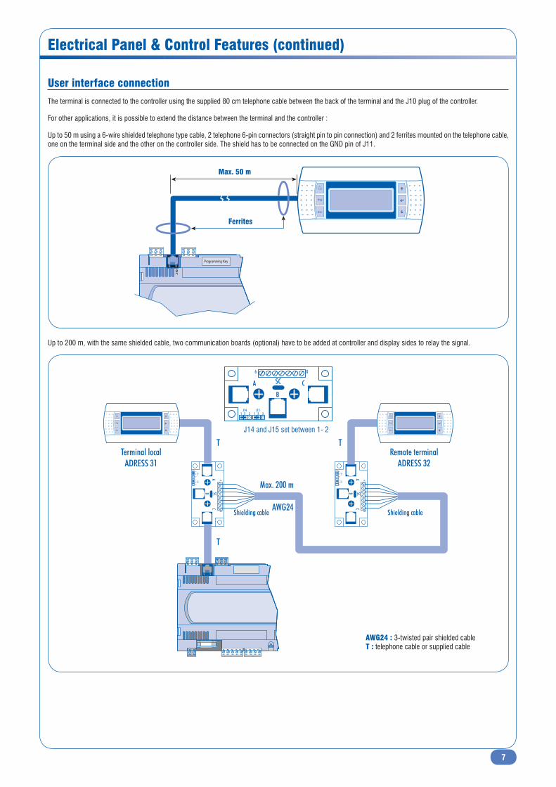
User interface connection
The terminal is connected to the controller using the supplied 80 cm telephone cable between the back of the terminal and the J10 plug of the controller.
For other applications, it is possible to extend the distance between the terminal and the controller :
Up to 50 m using a 6-wire shielded telephone type cable, 2 telephone 6-pin connectors (straight pin to pin connection) and 2 ferrites mounted on the telephone cable, one on the terminal side and the other on the controller side. The shield has to be connected on the GND pin of J11.
Programming Key
01JMax. 50 m
Ferrites
Up to 200 m, with the same shielded cable, two communication boards (optional) have to be added at controller and display sides to relay the signal.
06
A SC
B
C
1 2J14 J15
3 1 2 3
06A
SCB
C
12 J14
J153
12
3
06A
SCB
C
12 J14
J153
12
3
Terminal localADRESS 31
Remote terminalADRESS 32
T
Max. 200 m
AWG24Shielding cableShielding cable
T
T
J14 and J15 set between 1- 2
AWG24 : 3-twisted pair shielded cableT : telephone cable or supplied cable

8
Electrical Panel & Control Features (continued)
Multi-rooftop installation
For several rooftop installation (in different zones/groups or not), it is possible to display each unit parameters using only one interface display for the whole
installation. The principle is to connect all the units in parallel via one pLAN bus (internal protocol), while the display is connected to one master controller by using
the J10 plug. This IATC will centralize certain certain operation modes, such as "occupied/unoccupied" mode.
In pLAN, it is possible to connect up to 31 RTL/RTH rooftops identified by their individual address, the 32nd adress has to be dedicated to the display.
Connections example
Fuse
Programming Key
-xT/-xR
+xT/+xR
DN
G
G 0G
1J
11J
Fuse
Programming Key
-xT/-xR
+xT/+xR
DN
G
G 0G
1J
11J
Fuse
Programming Key
-xT/-xR
+xT/+xR
DN
G
G 0G
1J
11J
The connection between boards in pLAN is carried out using a 0.33 to 0.5 mm2 (AWG20/22) shielded cable, twisted pair + shield.
Adress 32
Adress 01 Adress 02 Adress 25....... ....... .......
9
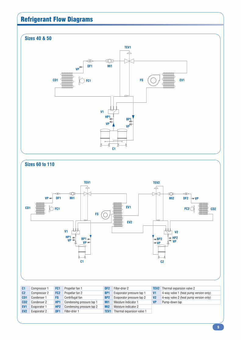
Refrigerant Flow Diagrams
Sizes 40 & 50
Sizes 60 to 110
V1
TEV1
MI1DF1
FC1 FS EV1CD1
HP1BP1
C1
VPVP
VP
V1
TEV1
MI1DF1
FC1
FS
EV1CD1
HP1 BP1
C1
HP2
MI2
V2
CD2FC2
DF2
BP2
C2
TEV2
EV2
VP VP
VP VPVPVP
C1 Compressor 1 FC1 Propellar fan 1 DF2 Filter-drier 2 TEV2 Thermal expansion valve 2C2 Compressor 2 FC2 Propellar fan 2 BP1 Evaporator pressure tap 1 V1 4-way valve 1 (heat pump version only)CD1 Condenser 1 FS Centrifugal fan BP2 Evaporator pressure tap 2 V2 4-way valve 2 (heat pump version only)CD2 Condenser 2 HP1 Condensing pressure tap 1 MI1 Moisture indicator 1 VP Pump-down tapEV1 Evaporator 1 HP2 Condensing pressure tap 2 MI2 Moisture indicator 2EV2 Evaporator 2 DF1 Filter-drier 1 TEV1 Thermal expansion valve 1
10
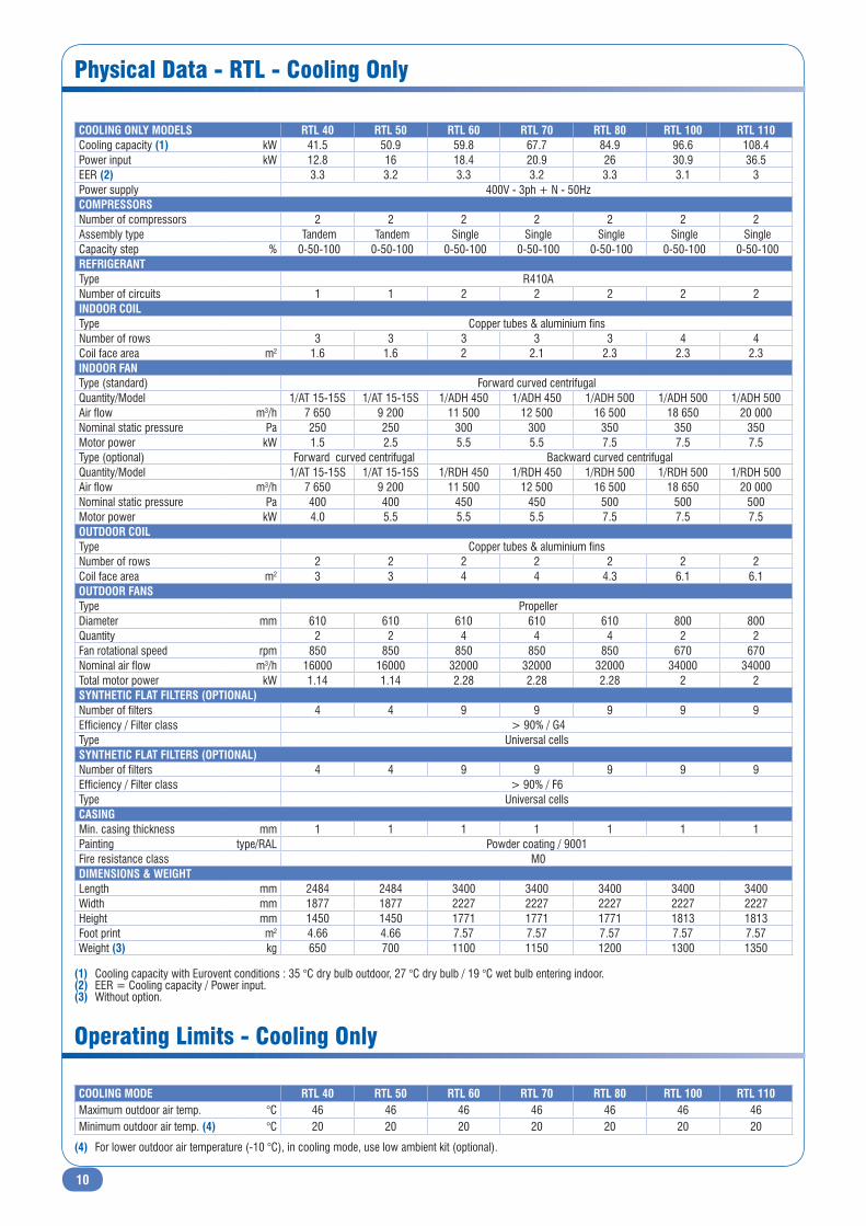
Physical Data - RTL - Cooling Only
Operating Limits - Cooling Only
COOLING MODE RTL 40 RTL 50 RTL 60 RTL 70 RTL 80 RTL 100 RTL 110Maximum outdoor air temp. °C 46 46 46 46 46 46 46Minimum outdoor air temp. (4) °C 20 20 20 20 20 20 20
(4) For lower outdoor air temperature (-10 °C), in cooling mode, use low ambient kit (optional).
(1) Cooling capacity with Eurovent conditions : 35 °C dry bulb outdoor, 27 °C dry bulb / 19 °C wet bulb entering indoor.(2) EER = Cooling capacity / Power input.(3) Without option.
COOLING ONLY MODELS RTL 40 RTL 50 RTL 60 RTL 70 RTL 80 RTL 100 RTL 110Cooling capacity (1) kW 41.5 50.9 59.8 67.7 84.9 96.6 108.4Power input kW 12.8 16 18.4 20.9 26 30.9 36.5EER (2) 3.3 3.2 3.3 3.2 3.3 3.1 3Power supply 400V - 3ph + N - 50Hz COMPRESSORSNumber of compressors 2 2 2 2 2 2 2Assembly type Tandem Tandem Single Single Single Single Single Capacity step % 0-50-100 0-50-100 0-50-100 0-50-100 0-50-100 0-50-100 0-50-100 REFRIGERANTType R410A Number of circuits 1 1 2 2 2 2 2INDOOR COILType Copper tubes & aluminium finsNumber of rows 3 3 3 3 3 4 4Coil face area m2 1.6 1.6 2 2.1 2.3 2.3 2.3INDOOR FANType (standard) Forward curved centrifugalQuantity/Model 1/AT 15-15S 1/AT 15-15S 1/ADH 450 1/ADH 450 1/ADH 500 1/ADH 500 1/ADH 500Air flow m3/h 7 650 9 200 11 500 12 500 16 500 18 650 20 000Nominal static pressure Pa 250 250 300 300 350 350 350Motor power kW 1.5 2.5 5.5 5.5 7.5 7.5 7.5Type (optional) Forward curved centrifugal Backward curved centrifugalQuantity/Model 1/AT 15-15S 1/AT 15-15S 1/RDH 450 1/RDH 450 1/RDH 500 1/RDH 500 1/RDH 500Air flow m3/h 7 650 9 200 11 500 12 500 16 500 18 650 20 000Nominal static pressure Pa 400 400 450 450 500 500 500Motor power kW 4.0 5.5 5.5 5.5 7.5 7.5 7.5OUTDOOR COILType Copper tubes & aluminium finsNumber of rows 2 2 2 2 2 2 2Coil face area m2 3 3 4 4 4.3 6.1 6.1OUTDOOR FANSType Propeller Diameter mm 610 610 610 610 610 800 800Quantity 2 2 4 4 4 2 2Fan rotational speed rpm 850 850 850 850 850 670 670Nominal air flow m3/h 16000 16000 32000 32000 32000 34000 34000Total motor power kW 1.14 1.14 2.28 2.28 2.28 2 2SYNTHETIC FLAT FILTERS (OPTIONAL) Number of filters 4 4 9 9 9 9 9Efficiency / Filter class > 90% / G4 Type Universal cellsSYNTHETIC FLAT FILTERS (OPTIONAL) Number of filters 4 4 9 9 9 9 9Efficiency / Filter class > 90% / F6 Type Universal cellsCASINGMin. casing thickness mm 1 1 1 1 1 1 1Painting type/RAL Powder coating / 9001Fire resistance class M0 DIMENSIONS & WEIGHTLength mm 2484 2484 3400 3400 3400 3400 3400Width mm 1877 1877 2227 2227 2227 2227 2227Height mm 1450 1450 1771 1771 1771 1813 1813Foot print m2 4.66 4.66 7.57 7.57 7.57 7.57 7.57Weight (3) kg 650 700 1100 1150 1200 1300 1350

11
Physical Data - RTH - Heat Pump Version
Operating Limits - Cooling and Heating Modes
COOLING MODE RTH 40 RTH 50 RTH 60 RTH 70 RTH 80 RTH 100 RTH 110Maximum outdoor air temp. °C 46 46 46 46 46 46 46Minimum outdoor air temp. (6) °C 20 20 20 20 20 20 20HEATING MODE RTH 40 RTH 50 RTH 60 RTH 70 RTH 80 RTH 100 RTH 110Maximum outdoor air temp. °C 21 21 21 21 21 21 21Minimum outdoor air temp. °C -10 -10 -10 -10 -10 -10 -10
(6) For lower outdoor air temperature (-10 °C), in cooling mode, use low ambient kit (optional).
(1) Cooling capacity with Eurovent conditions : 35 °C dry bulb outdoor, 27 °C dry bulb / 19 °C wet bulb entering indoor.(2) EER = Cooling capacity / Effective power input.(3) Heating capacity with Eurovent conditions : 7 °C dry bulb / 6 °C wet bulb outdoor, 20 °C entering indoor.(4) COP = Heating capacity / Power input.(5) Without option.
HEAT PUMP MODELS RTH 40 RTH 50 RTH 60 RTH 70 RTH 80 RTH 100 RTH 110Cooling capacity (1) kW 41 48.6 59 66 83.4 94.8 106.1Power input kW 12.8 16 18.4 20.9 26 30.9 36.5EER - Cooling mode (2) 3.2 3 3.2 3.2 3.2 3.1 2.9Heating capacity (3) kW 42.9 50.2 58.2 66.5 84 96 108Power input kW 12.2 15.1 17.8 20.3 24.1 28.5 33.7COP - Heating mode (4) 3.5 3.3 3.3 3.3 3.5 3.4 3.2Power supply 400V - 3ph + N - 50Hz REFRIGERANTType R410A Number of circuits 1 1 2 2 2 2 2COMPRESSORSNumber of compressors 2 2 2 2 2 2 2Assembly type Tandem Tandem Single Single Single Single SingleCapacity step % 0-50-100 0-50-100 0-50-100 0-50-100 0-50-100 0-50-100 0-50-100 INDOOR COILType Copper tubes & aluminium finsNumber of rows 3 3 3 3 3 4 4Coil face area m2 1.6 1.6 2 2.1 2.3 2.3 2.3INDOOR FANType (standard) Forward curved centrifugalQuantity/Model 1/AT 15-15S 1/AT 15-15S 1/ADH 450 1/ADH 450 1/ADH 500 1/ADH 500 1/ADH 500Air flow m3/h 7 650 9 200 11 500 12 500 16 500 18 650 20 000Nominal static pressure Pa 250 250 300 300 350 350 350Motor power kW 1.5 2.5 5.5 5.5 7.5 7.5 7.5Type (optional) Forward curved centrifugal Backward curved centrifugalQuantity/Model 1/AT 15-15S 1/AT 15-15S 1/RDH 450 1/RDH 450 1/RDH 500 1/RDH 500 1/RDH 500Air flow m3/h 7 650 9 200 11 500 12 500 16 500 18 650 20 000Nominal static pressure Pa 400 400 450 450 500 500 500Motor power kW 4 5.5 5.5 5.5 7.5 7.5 7.5OUTDOOR COILType Copper tubes & aluminium finsNumber of rows 2 2 2 2 2 2 2Coil face area m2 3 3 4 4 4.3 6.1 6.1OUTDOOR FANSType PropellerDiameter mm 610 610 610 610 610 800 800Quantity 2 2 4 4 4 2 2Fan rotational speed rpm 850 850 850 850 850 670 670Nominal air flow m3/h 16000 16000 32000 32000 32000 34000 34000Total motor power kW 1.14 1.14 2.28 2.28 2.28 2 2SYNTHETIC FLAT FILTERS (OPTIONAL) Number of filters 4 4 9 9 9 9 9Efficiency / Filter class > 90% / G4 Type Universal cellsSYNTHETIC FLAT FILTERS (OPTIONAL) Number of filters 4 4 9 9 9 9 9Efficiency / Filter class > 90% / F6 Type Universal cellsCASINGMin. casing thickness mm 1 1 1 1 1 1 1Painting type/RAL Powder coating / 9001Fire resistance class M0 DIMENSIONS & WEIGHTLength mm 2484 2484 3400 3400 3400 3400 3400Width mm 1877 1877 2227 2227 2227 2227 2227Height mm 1450 1450 1771 1771 1771 1813 1813Foot print m2 4.66 4.66 7.57 7.57 7.57 7.57 7.57Weight (5) kg 650 700 1100 1150 1200 1300 1350
12
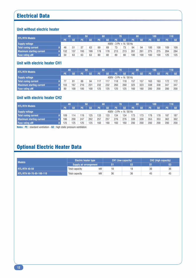
Electrical Data
ModelsElectric heater type CH1 (low capacity) CH2 (high capacity)
Supply air arrangement S1 S3 S1 S3
RTL/RTH 40-50 Total capacity kW 18 18 36 36
RTL/RTH 60-70-80-100-110 Total capacity kW 36 36 45 45
Optional Electric Heater Data
Unit without electric heater
Unit with electric heater CH1
Unit with electric heater CH2
Notes : PE : standard ventilation - GE : high static pressure ventilation.
RTL/RTH Models40 50 60 70 80 100 110
PE GE PE GE PE GE PE GE PE GE PE GE PE GESupply voltage 400V - 3 Ph + N / 50 HzTotal runing current A 46 51 57 63 69 69 73 73 94 94 100 100 109 109Maximum starting current A 132 137 193 199 178 178 213 213 261 261 275 275 284 284Fuse rating aM A 50 63 63 63 80 80 80 80 100 100 100 100 125 125
RTL/RTH Models40 50 60 70 80 100 110
PE GE PE GE PE GE PE GE PE GE PE GE PE GESupply voltage 400V - 3 Ph + N / 50 HzTotal runing current A 77 81 88 94 117 117 118 118 157 157 163 163 172 172Maximum starting current A 155 167 216 231 232 232 260 260 323 323 338 338 347 347Fuse rating aM A 80 100 100 100 125 125 125 125 160 160 200 200 200 200
RTL/RTH Models40 50 60 70 80 100 110
PE GE PE GE PE GE PE GE PE GE PE GE PE GESupply voltage 400V - 3 Ph + N / 50 HzTotal runing current A 109 114 119 125 133 133 134 134 173 173 178 178 187 187Maximum starting current A 186 200 247 262 257 257 276 276 339 339 353 353 362 362Fuse rating aM A 125 125 125 125 160 160 160 160 200 200 200 200 200 200

13
Cooling Capacity Data - RTL 40 - Nominal Airflow 7650 m3/h
INDOOR COIL ENTERING AIR TEMPERATURE (°C) OUTDOOR AIR TEMPERATURE (°C)20 25 30 35 40 45
Wet bulb temperature = 15 °C Total cooling capacity (kW) 41.3 39.8 38.2 36.7 35.1 33.6Total power input (kW) 10.6 11.3 11.9 12.5 13.1 13.7
Dry bulb temperature
21 °C
Sensible coolingcapacity (kW)
27.7 28.3 28.9 29.5 30.0 30.623 °C 31.1 31.8 32.5 33.1 33.8 33.625 °C 34.6 39.6 38.2 36.7 35.1 33.627 °C 41.3 39.8 38.2 36.7 35.1 33.629 °C 41.3 39.8 38.2 36.7 35.1 33.631 °C 41.3 39.8 38.2 36.7 35.1 33.6
Wet bulb temperature = 17 °C Total cooling capacity (kW) 43.9 42.3 40.7 39.1 37.5 35.8Total power input (kW) 10.7 11.4 12.0 12.6 13.2 13.8
Dry bulb temperature
21 °C
Sensible coolingcapacity (kW)
26.7 27.2 27.8 28.4 29.0 29.523 °C 30.4 31.0 31.6 32.3 32.9 33.625 °C 34.0 34.8 35.5 36.2 36.9 35.527 °C 41.8 41.3 40.7 39.1 37.5 35.829 °C 43.5 42.3 40.7 39.1 37.5 35.831 °C 43.9 42.3 40.7 39.1 37.5 35.8
Wet bulb temperature = 19 °C Total cooling capacity (kW) 46.5 44.9 43.2 41.5 39.8 38.1Total power input (kW) 10.9 11.5 12.2 12.8 13.4 14.1
Dry bulb temperature
21 °C
Sensible coolingcapacity (kW)
21.5 21.9 22.4 22.8 23.3 23.723 °C 25.4 25.9 26.4 27.0 27.5 28.125 °C 29.3 29.9 30.5 31.1 31.7 32.427 °C 33.2 33.9 34.6 35.3 36.0 36.729 °C 37.1 37.8 38.6 39.4 39.8 38.131 °C 45.2 44.8 43.2 41.5 39.8 38.1
Wet bulb temperature = 21 °C Total cooling capacity (kW) 49.3 47.5 45.8 44.0 42.2 40.5Total power input (kW) 11.4 12.0 12.7 13.3 14.0 14.7
Dry bulb temperature
23 °C
Sensible coolingcapacity (kW)
19.6 20.0 20.4 20.8 21.3 21.725 °C 23.7 24.2 24.7 25.2 25.7 26.327 °C 27.9 28.5 29.1 29.6 30.2 30.829 °C 32.0 32.7 33.4 34.0 34.7 35.431 °C 36.1 36.9 37.7 38.4 39.2 40.033 °C 40.3 41.1 45.9 45.0 43.8 42.4
Wet bulb temperature = 23 °C Total cooling capacity (kW) 52.1 50.2 48.4 46.5 44.7 42.8Total power input (kW) 11.9 12.6 13.3 13.9 14.6 15.3
Dry bulb temperature
25 °CSensible coolingcapacity (kW)
17.4 17.7 18.1 18.5 18.9 19.227 °C 21.8 22.2 22.7 23.1 23.6 24.129 °C 26.1 26.7 27.2 27.8 28.4 28.931 °C 30.5 31.2 31.8 32.5 33.1 33.733 °C 34.9 35.6 36.4 37.1 37.8 38.6
14
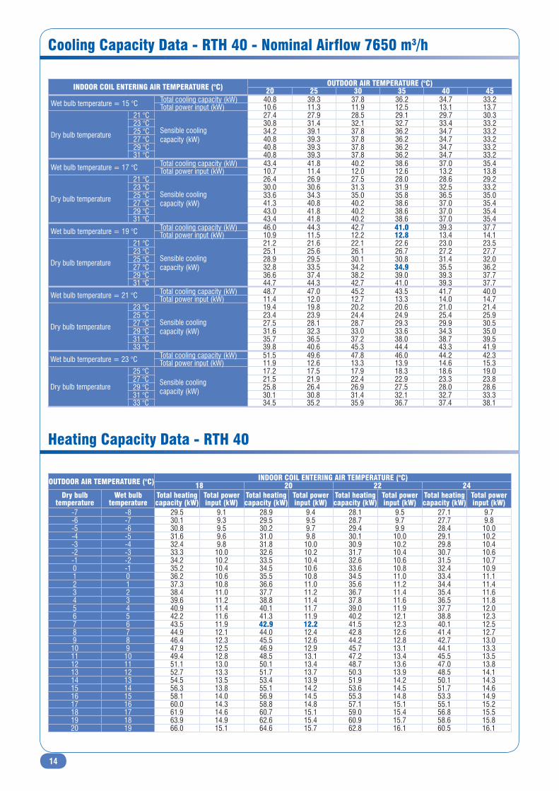
Cooling Capacity Data - RTH 40 - Nominal Airflow 7650 m3/h
Heating Capacity Data - RTH 40
INDOOR COIL ENTERING AIR TEMPERATURE (°C) OUTDOOR AIR TEMPERATURE (°C)20 25 30 35 40 45
Wet bulb temperature = 15 °C Total cooling capacity (kW) 40.8 39.3 37.8 36.2 34.7 33.2Total power input (kW) 10.6 11.3 11.9 12.5 13.1 13.7
Dry bulb temperature
21 °C
Sensible coolingcapacity (kW)
27.4 27.9 28.5 29.1 29.7 30.323 °C 30.8 31.4 32.1 32.7 33.4 33.225 °C 34.2 39.1 37.8 36.2 34.7 33.227 °C 40.8 39.3 37.8 36.2 34.7 33.229 °C 40.8 39.3 37.8 36.2 34.7 33.231 °C 40.8 39.3 37.8 36.2 34.7 33.2
Wet bulb temperature = 17 °C Total cooling capacity (kW) 43.4 41.8 40.2 38.6 37.0 35.4Total power input (kW) 10.7 11.4 12.0 12.6 13.2 13.8
Dry bulb temperature
21 °C
Sensible coolingcapacity (kW)
26.4 26.9 27.5 28.0 28.6 29.223 °C 30.0 30.6 31.3 31.9 32.5 33.225 °C 33.6 34.3 35.0 35.8 36.5 35.027 °C 41.3 40.8 40.2 38.6 37.0 35.429 °C 43.0 41.8 40.2 38.6 37.0 35.431 °C 43.4 41.8 40.2 38.6 37.0 35.4
Wet bulb temperature = 19 °C Total cooling capacity (kW) 46.0 44.3 42.7 41.0 39.3 37.7Total power input (kW) 10.9 11.5 12.2 12.8 13.4 14.1
Dry bulb temperature
21 °C
Sensible coolingcapacity (kW)
21.2 21.6 22.1 22.6 23.0 23.523 °C 25.1 25.6 26.1 26.7 27.2 27.725 °C 28.9 29.5 30.1 30.8 31.4 32.027 °C 32.8 33.5 34.2 34.9 35.5 36.229 °C 36.6 37.4 38.2 39.0 39.3 37.731 °C 44.7 44.3 42.7 41.0 39.3 37.7
Wet bulb temperature = 21 °C Total cooling capacity (kW) 48.7 47.0 45.2 43.5 41.7 40.0Total power input (kW) 11.4 12.0 12.7 13.3 14.0 14.7
Dry bulb temperature
23 °C
Sensible coolingcapacity (kW)
19.4 19.8 20.2 20.6 21.0 21.425 °C 23.4 23.9 24.4 24.9 25.4 25.927 °C 27.5 28.1 28.7 29.3 29.9 30.529 °C 31.6 32.3 33.0 33.6 34.3 35.031 °C 35.7 36.5 37.2 38.0 38.7 39.533 °C 39.8 40.6 45.3 44.4 43.3 41.9
Wet bulb temperature = 23 °C Total cooling capacity (kW) 51.5 49.6 47.8 46.0 44.2 42.3Total power input (kW) 11.9 12.6 13.3 13.9 14.6 15.3
Dry bulb temperature
25 °CSensible coolingcapacity (kW)
17.2 17.5 17.9 18.3 18.6 19.027 °C 21.5 21.9 22.4 22.9 23.3 23.829 °C 25.8 26.4 26.9 27.5 28.0 28.631 °C 30.1 30.8 31.4 32.1 32.7 33.333 °C 34.5 35.2 35.9 36.7 37.4 38.1
OUTDOOR AIR TEMPERATURE (°C) INDOOR COIL ENTERING AIR TEMPERATURE (°C)18 20 22 24
Dry bulbtemperature
Wet bulbtemperature
Total heating capacity (kW)
Total power input (kW)
Total heating capacity (kW)
Total power input (kW)
Total heating capacity (kW)
Total power input (kW)
Total heating capacity (kW)
Total power input (kW)
-7 -8 29.5 9.1 28.9 9.4 28.1 9.5 27.1 9.7-6 -7 30.1 9.3 29.5 9.5 28.7 9.7 27.7 9.8-5 -6 30.8 9.5 30.2 9.7 29.4 9.9 28.4 10.0-4 -5 31.6 9.6 31.0 9.8 30.1 10.0 29.1 10.2-3 -4 32.4 9.8 31.8 10.0 30.9 10.2 29.8 10.4-2 -3 33.3 10.0 32.6 10.2 31.7 10.4 30.7 10.6-1 -2 34.2 10.2 33.5 10.4 32.6 10.6 31.5 10.70 -1 35.2 10.4 34.5 10.6 33.6 10.8 32.4 10.91 0 36.2 10.6 35.5 10.8 34.5 11.0 33.4 11.12 1 37.3 10.8 36.6 11.0 35.6 11.2 34.4 11.43 2 38.4 11.0 37.7 11.2 36.7 11.4 35.4 11.64 3 39.6 11.2 38.8 11.4 37.8 11.6 36.5 11.85 4 40.9 11.4 40.1 11.7 39.0 11.9 37.7 12.06 5 42.2 11.6 41.3 11.9 40.2 12.1 38.8 12.37 6 43.5 11.9 42.9 12.2 41.5 12.3 40.1 12.58 7 44.9 12.1 44.0 12.4 42.8 12.6 41.4 12.79 8 46.4 12.3 45.5 12.6 44.2 12.8 42.7 13.0
10 9 47.9 12.5 46.9 12.9 45.7 13.1 44.1 13.311 10 49.4 12.8 48.5 13.1 47.2 13.4 45.5 13.512 11 51.1 13.0 50.1 13.4 48.7 13.6 47.0 13.813 12 52.7 13.3 51.7 13.7 50.3 13.9 48.5 14.114 13 54.5 13.5 53.4 13.9 51.9 14.2 50.1 14.315 14 56.3 13.8 55.1 14.2 53.6 14.5 51.7 14.616 15 58.1 14.0 56.9 14.5 55.3 14.8 53.3 14.917 16 60.0 14.3 58.8 14.8 57.1 15.1 55.1 15.218 17 61.9 14.6 60.7 15.1 59.0 15.4 56.8 15.519 18 63.9 14.9 62.6 15.4 60.9 15.7 58.6 15.820 19 66.0 15.1 64.6 15.7 62.8 16.1 60.5 16.1
15
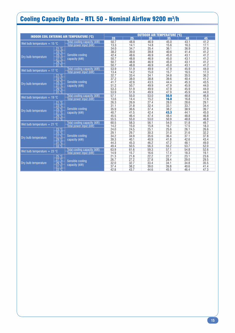
Cooling Capacity Data - RTL 50 - Nominal Airflow 9200 m3/h
INDOOR COIL ENTERING AIR TEMPERATURE (°C) OUTDOOR AIR TEMPERATURE (°C)20 25 30 35 40 45
Wet bulb temperature = 15 °C Total cooling capacity (kW) 50.7 48.8 46.9 45.0 43.1 41.2Total power input (kW) 13.3 14.1 14.8 15.6 16.3 17.1
Dry bulb temperature
21 °C
Sensible coolingcapacity (kW)
34.0 34.7 35.4 36.1 36.9 37.623 °C 38.2 39.0 39.8 40.6 41.4 41.225 °C 42.4 48.6 46.9 45.0 43.1 41.227 °C 50.7 48.8 46.9 45.0 43.1 41.229 °C 50.7 48.8 46.9 45.0 43.1 41.231 °C 50.7 48.8 46.9 45.0 43.1 41.2
Wet bulb temperature = 17 °C Total cooling capacity (kW) 53.9 51.9 49.9 47.9 45.9 44.0Total power input (kW) 13.4 14.2 15.0 15.7 16.5 17.3
Dry bulb temperature
21 °C
Sensible coolingcapacity (kW)
32.7 33.4 34.1 34.8 35.5 36.223 °C 37.2 38.0 38.8 39.6 40.4 41.225 °C 41.7 42.6 43.5 44.4 45.3 43.527 °C 51.2 50.7 49.9 47.9 45.9 44.029 °C 53.3 51.9 49.9 47.9 45.9 44.031 °C 53.9 51.9 49.9 47.9 45.9 44.0
Wet bulb temperature = 19 °C Total cooling capacity (kW) 57.1 55.0 53.0 50.9 48.8 46.8Total power input (kW) 13.6 14.4 15.2 16.0 16.8 17.6
Dry bulb temperature
21 °C
Sensible coolingcapacity (kW)
26.3 26.9 27.4 28.0 28.6 29.123 °C 31.1 31.8 32.4 33.1 33.7 34.425 °C 35.9 36.6 37.4 38.2 38.9 39.727 °C 40.7 41.5 42.4 43.3 44.1 45.029 °C 45.5 46.4 47.4 48.4 48.8 46.831 °C 55.5 55.0 53.0 50.9 48.8 46.8
Wet bulb temperature = 21 °C Total cooling capacity (kW) 60.5 58.3 56.1 54.0 51.8 49.7Total power input (kW) 14.2 15.0 15.8 16.7 17.5 18.3
Dry bulb temperature
23 °C
Sensible coolingcapacity (kW)
24.0 24.5 25.1 25.6 26.1 26.625 °C 29.1 29.7 30.3 31.0 31.6 32.227 °C 34.2 34.9 35.6 36.4 37.1 37.829 °C 39.3 40.1 40.9 41.8 42.6 43.431 °C 44.3 45.3 46.2 47.2 48.1 49.033 °C 49.4 50.5 56.3 55.2 53.7 52.0
Wet bulb temperature = 23 °C Total cooling capacity (kW) 63.9 61.6 59.3 57.1 54.8 52.6Total power input (kW) 14.9 15.7 16.6 17.4 18.3 19.1
Dry bulb temperature
25 °CSensible coolingcapacity (kW)
21.3 21.8 22.2 22.7 23.1 23.627 °C 26.7 27.2 27.8 28.4 29.0 29.529 °C 32.0 32.7 33.4 34.1 34.8 35.531 °C 37.4 38.2 39.0 39.8 40.6 41.433 °C 42.8 43.7 44.6 45.5 46.4 47.3

16
Cooling Capacity Data - RTH 50 - Nominal Airflow 9200 m3/h
Heating Capacity Data - RTH 50
INDOOR COIL ENTERING AIR TEMPERATURE (°C) OUTDOOR AIR TEMPERATURE (°C)20 25 30 35 40 45
Wet bulb temperature = 15 °C Total cooling capacity (kW) 48.4 46.6 44.8 43.0 41.1 39.3Total power input (kW) 13.4 14.2 14.9 15.7 16.4 17.2
Dry bulb temperature
21 °C
Sensible coolingcapacity (kW)
32.4 33.1 33.8 34.5 35.2 35.923 °C 36.5 37.2 38.0 38.8 39.6 39.325 °C 40.5 46.4 44.8 43.0 41.1 39.327 °C 48.4 46.6 44.8 43.0 41.1 39.329 °C 48.4 46.6 44.8 43.0 41.1 39.331 °C 48.4 46.6 44.8 43.0 41.1 39.3
Wet bulb temperature = 17 °C Total cooling capacity (kW) 51.5 49.6 47.7 45.8 43.9 42.0Total power input (kW) 13.5 14.3 15.1 15.8 16.6 17.4
Dry bulb temperature
21 °C
Sensible coolingcapacity (kW)
31.2 31.9 32.6 33.2 33.9 34.623 °C 35.5 36.3 37.1 37.8 38.6 39.325 °C 39.9 40.7 41.5 42.4 43.2 41.527 °C 48.9 48.4 47.6 45.8 43.9 42.029 °C 50.9 49.6 47.7 45.8 43.9 42.031 °C 51.5 49.6 47.7 45.8 43.9 42.0
Wet bulb temperature = 19 °C Total cooling capacity (kW) 54.5 52.5 50.6 48.6 46.6 44.7Total power input (kW) 13.7 14.5 15.3 16.1 16.9 17.7
Dry bulb temperature
21 °C
Sensible coolingcapacity (kW)
25.1 25.7 26.2 26.7 27.3 27.823 °C 29.7 30.3 31.0 31.6 32.2 32.925 °C 34.3 35.0 35.7 36.5 37.2 37.927 °C 38.8 39.7 40.5 41.3 42.1 43.029 °C 43.4 44.3 45.2 46.2 46.6 44.731 °C 53.0 52.5 50.6 48.6 46.6 44.7
Wet bulb temperature = 21 °C Total cooling capacity (kW) 57.7 55.7 53.6 51.5 49.5 47.4Total power input (kW) 14.3 15.1 15.9 16.8 17.6 18.4
Dry bulb temperature
23 °C
Sensible coolingcapacity (kW)
22.9 23.4 23.9 24.4 24.9 25.425 °C 27.8 28.4 29.0 29.6 30.2 30.727 °C 32.6 33.3 34.0 34.7 35.4 36.129 °C 37.5 38.3 39.1 39.9 40.7 41.531 °C 42.3 43.2 44.1 45.0 45.9 46.833 °C 47.2 48.2 53.7 52.7 51.3 49.6
Wet bulb temperature = 23 °C Total cooling capacity (kW) 61.0 58.8 56.7 54.5 52.3 50.2Total power input (kW) 15.0 15.8 16.7 17.5 18.4 19.2
Dry bulb temperature
25 °CSensible coolingcapacity (kW)
20.4 20.8 21.2 21.7 22.1 22.527 °C 25.5 26.0 26.6 27.1 27.6 28.229 °C 30.6 31.3 31.9 32.6 33.2 33.931 °C 35.7 36.5 37.2 38.0 38.8 39.533 °C 40.8 41.7 42.6 43.5 44.3 45.2
OUTDOOR AIR TEMPERATURE (°C) INDOOR COIL ENTERING AIR TEMPERATURE (°C)18 20 22 24
Dry bulbtemperature
Wet bulbtemperature
Total heating capacity (kW)
Total power input (kW)
Total heating capacity (kW)
Total power input (kW)
Total heating capacity (kW)
Total power input (kW)
Total heating capacity (kW)
Total power input (kW)
-7 -8 34.5 11.4 33.8 11.7 32.9 11.9 31.7 12.1-6 -7 35.2 11.6 34.5 11.8 33.6 12.1 32.4 12.3-5 -6 36.1 11.8 35.4 12.1 34.4 12.3 33.2 12.5-4 -5 37.0 12.0 36.2 12.3 35.3 12.5 34.0 12.7-3 -4 37.9 12.2 37.2 12.5 36.2 12.7 34.9 12.9-2 -3 38.9 12.5 38.2 12.7 37.1 12.9 35.9 13.1-1 -2 40.0 12.7 39.2 12.9 38.2 13.2 36.9 13.40 -1 41.2 12.9 40.3 13.2 39.3 13.4 37.9 13.61 0 42.4 13.2 41.5 13.4 40.4 13.7 39.0 13.92 1 43.6 13.4 42.8 13.7 41.6 13.9 40.2 14.23 2 45.0 13.7 44.1 14.0 42.9 14.2 41.4 14.44 3 46.3 14.0 45.4 14.2 44.2 14.5 42.7 14.75 4 47.8 14.2 46.9 14.5 45.6 14.8 44.1 15.06 5 49.3 14.5 48.4 14.8 47.1 15.1 45.5 15.37 6 50.9 14.8 50.2 15.2 48.6 15.4 46.9 15.68 7 52.6 15.1 51.5 15.4 50.1 15.7 48.4 15.99 8 54.3 15.3 53.2 15.7 51.8 16.0 50.0 16.2
10 9 56.0 15.6 54.9 16.0 53.4 16.3 51.6 16.511 10 57.9 15.9 56.7 16.3 55.2 16.7 53.2 16.812 11 59.8 16.2 58.6 16.7 57.0 17.0 55.0 17.213 12 61.7 16.5 60.5 17.0 58.8 17.3 56.8 17.514 13 63.7 16.9 62.5 17.4 60.8 17.7 58.6 17.915 14 65.8 17.2 64.5 17.7 62.7 18.1 60.5 18.216 15 68.0 17.5 66.6 18.1 64.8 18.4 62.4 18.617 16 70.2 17.8 68.8 18.5 66.9 18.8 64.4 19.018 17 72.5 18.2 71.0 18.8 69.0 19.2 66.5 19.319 18 74.8 18.5 73.3 19.2 71.2 19.6 68.6 19.720 19 77.2 18.9 75.6 19.6 73.5 20.0 70.8 20.1
17
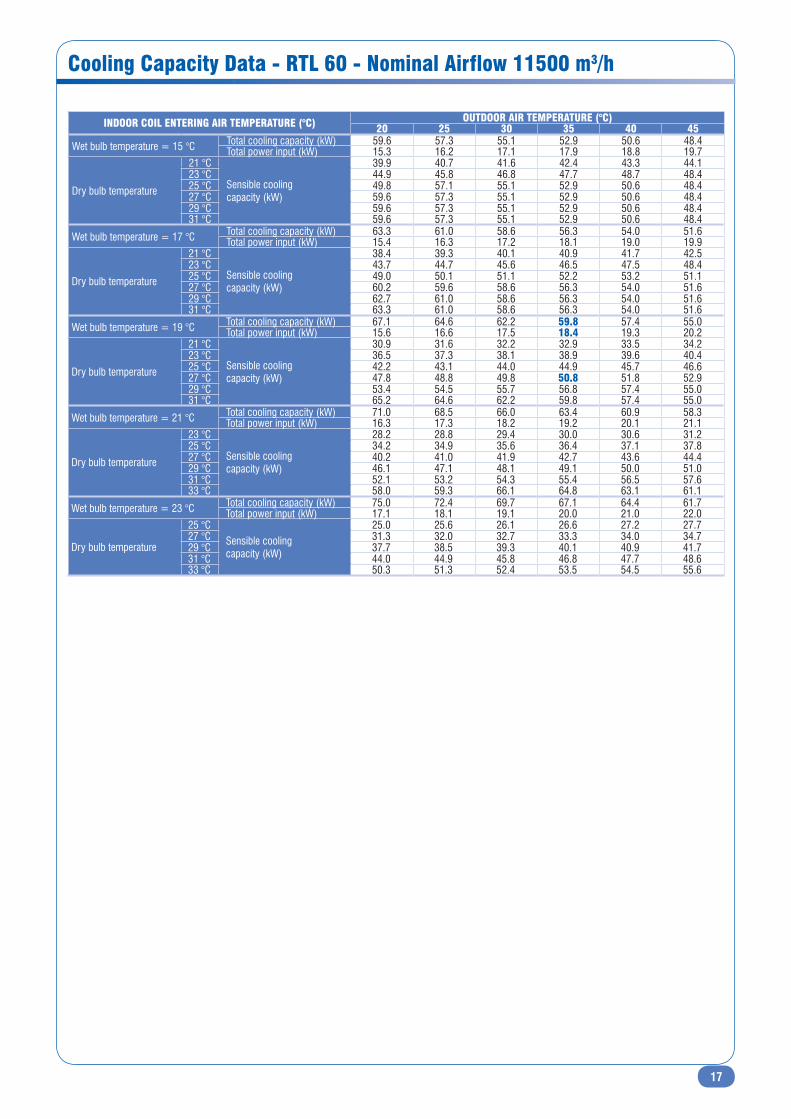
Cooling Capacity Data - RTL 60 - Nominal Airflow 11500 m3/h
INDOOR COIL ENTERING AIR TEMPERATURE (°C) OUTDOOR AIR TEMPERATURE (°C)20 25 30 35 40 45
Wet bulb temperature = 15 °C Total cooling capacity (kW) 59.6 57.3 55.1 52.9 50.6 48.4Total power input (kW) 15.3 16.2 17.1 17.9 18.8 19.7
Dry bulb temperature
21 °C
Sensible coolingcapacity (kW)
39.9 40.7 41.6 42.4 43.3 44.123 °C 44.9 45.8 46.8 47.7 48.7 48.425 °C 49.8 57.1 55.1 52.9 50.6 48.427 °C 59.6 57.3 55.1 52.9 50.6 48.429 °C 59.6 57.3 55.1 52.9 50.6 48.431 °C 59.6 57.3 55.1 52.9 50.6 48.4
Wet bulb temperature = 17 °C Total cooling capacity (kW) 63.3 61.0 58.6 56.3 54.0 51.6Total power input (kW) 15.4 16.3 17.2 18.1 19.0 19.9
Dry bulb temperature
21 °C
Sensible coolingcapacity (kW)
38.4 39.3 40.1 40.9 41.7 42.523 °C 43.7 44.7 45.6 46.5 47.5 48.425 °C 49.0 50.1 51.1 52.2 53.2 51.127 °C 60.2 59.6 58.6 56.3 54.0 51.629 °C 62.7 61.0 58.6 56.3 54.0 51.631 °C 63.3 61.0 58.6 56.3 54.0 51.6
Wet bulb temperature = 19 °C Total cooling capacity (kW) 67.1 64.6 62.2 59.8 57.4 55.0Total power input (kW) 15.6 16.6 17.5 18.4 19.3 20.2
Dry bulb temperature
21 °C
Sensible coolingcapacity (kW)
30.9 31.6 32.2 32.9 33.5 34.223 °C 36.5 37.3 38.1 38.9 39.6 40.425 °C 42.2 43.1 44.0 44.9 45.7 46.627 °C 47.8 48.8 49.8 50.8 51.8 52.929 °C 53.4 54.5 55.7 56.8 57.4 55.031 °C 65.2 64.6 62.2 59.8 57.4 55.0
Wet bulb temperature = 21 °C Total cooling capacity (kW) 71.0 68.5 66.0 63.4 60.9 58.3Total power input (kW) 16.3 17.3 18.2 19.2 20.1 21.1
Dry bulb temperature
23 °C
Sensible coolingcapacity (kW)
28.2 28.8 29.4 30.0 30.6 31.225 °C 34.2 34.9 35.6 36.4 37.1 37.827 °C 40.2 41.0 41.9 42.7 43.6 44.429 °C 46.1 47.1 48.1 49.1 50.0 51.031 °C 52.1 53.2 54.3 55.4 56.5 57.633 °C 58.0 59.3 66.1 64.8 63.1 61.1
Wet bulb temperature = 23 °C Total cooling capacity (kW) 75.0 72.4 69.7 67.1 64.4 61.7Total power input (kW) 17.1 18.1 19.1 20.0 21.0 22.0
Dry bulb temperature
25 °CSensible coolingcapacity (kW)
25.0 25.6 26.1 26.6 27.2 27.727 °C 31.3 32.0 32.7 33.3 34.0 34.729 °C 37.7 38.5 39.3 40.1 40.9 41.731 °C 44.0 44.9 45.8 46.8 47.7 48.633 °C 50.3 51.3 52.4 53.5 54.5 55.6

18
Cooling Capacity Data - RTH 60 - Nominal Airflow 11500 m3/h
Heating Capacity Data - RTH 60
INDOOR COIL ENTERING AIR TEMPERATURE (°C) OUTDOOR AIR TEMPERATURE (°C)20 25 30 35 40 45
Wet bulb temperature = 15 °C Total cooling capacity (kW) 58.8 56.6 54.4 52.1 49.9 47.7Total power input (kW) 15.3 16.2 17.1 17.9 18.8 19.7
Dry bulb temperature
21 °C
Sensible coolingcapacity (kW)
39.4 40.2 41.0 41.9 42.7 43.623 °C 44.3 45.2 46.2 47.1 48.0 47.725 °C 49.2 56.3 54.4 52.1 49.9 47.727 °C 58.8 56.6 54.4 52.1 49.9 47.729 °C 58.8 56.6 54.4 52.1 49.9 47.731 °C 58.8 56.6 54.4 52.1 49.9 47.7
Wet bulb temperature = 17 °C Total cooling capacity (kW) 62.5 60.2 57.9 55.6 53.3 51.0Total power input (kW) 15.4 16.3 17.2 18.1 19.0 19.9
Dry bulb temperature
21 °C
Sensible coolingcapacity (kW)
37.9 38.7 39.5 40.4 41.2 42.023 °C 43.2 44.1 45.0 45.9 46.8 47.725 °C 48.4 49.4 50.4 51.5 52.5 50.427 °C 59.4 58.8 57.8 55.6 53.3 51.029 °C 61.8 60.2 57.9 55.6 53.3 51.031 °C 62.5 60.2 57.9 55.6 53.3 51.0
Wet bulb temperature = 19 °C Total cooling capacity (kW) 66.2 63.8 61.4 59.0 56.6 54.2Total power input (kW) 15.6 16.6 17.5 18.4 19.3 20.2
Dry bulb temperature
21 °C
Sensible coolingcapacity (kW)
30.5 31.2 31.8 32.5 33.1 33.723 °C 36.0 36.8 37.6 38.4 39.1 39.925 °C 41.6 42.5 43.4 44.3 45.1 46.027 °C 47.1 48.1 49.1 50.2 51.2 52.229 °C 52.7 53.8 54.9 56.1 56.6 54.231 °C 64.3 63.7 61.4 59.0 56.6 54.2
Wet bulb temperature = 21 °C Total cooling capacity (kW) 70.1 67.6 65.1 62.6 60.1 57.6Total power input (kW) 16.3 17.3 18.2 19.2 20.1 21.1
Dry bulb temperature
23 °C
Sensible coolingcapacity (kW)
27.9 28.4 29.0 29.6 30.2 30.825 °C 33.7 34.5 35.2 35.9 36.6 37.327 °C 39.6 40.5 41.3 42.1 43.0 43.829 °C 45.5 46.5 47.4 48.4 49.4 50.331 °C 51.4 52.5 53.6 54.7 55.8 56.833 °C 57.3 58.5 65.2 63.9 62.3 60.3
Wet bulb temperature = 23 °C Total cooling capacity (kW) 74.0 71.4 68.8 66.2 63.5 60.9Total power input (kW) 17.1 18.1 19.1 20.0 21.0 22.0
Dry bulb temperature
25 °CSensible coolingcapacity (kW)
24.7 25.2 25.8 26.3 26.8 27.327 °C 30.9 31.6 32.2 32.9 33.6 34.229 °C 37.1 37.9 38.7 39.5 40.3 41.131 °C 43.4 44.3 45.2 46.1 47.1 48.033 °C 49.6 50.6 51.7 52.8 53.8 54.9
OUTDOOR AIR TEMPERATURE (°C) INDOOR COIL ENTERING AIR TEMPERATURE (°C)18 20 22 24
Dry bulbtemperature
Wet bulbtemperature
Total heating capacity (kW)
Total power input (kW)
Total heating capacity (kW)
Total power input (kW)
Total heating capacity (kW)
Total power input (kW)
Total heating capacity (kW)
Total power input (kW)
-7 -8 40.0 13.3 39.2 13.6 38.1 13.9 36.7 14.1-6 -7 40.9 13.6 40.1 13.9 39.0 14.1 37.6 14.4-5 -6 41.8 13.8 41.0 14.1 39.9 14.4 38.5 14.6-4 -5 42.9 14.1 42.0 14.4 40.9 14.6 39.5 14.9-3 -4 44.0 14.3 43.1 14.6 41.9 14.9 40.5 15.1-2 -3 45.1 14.6 44.3 14.9 43.1 15.2 41.6 15.4-1 -2 46.4 14.9 45.5 15.2 44.3 15.4 42.8 15.70 -1 47.7 15.2 46.8 15.4 45.5 15.7 44.0 16.01 0 49.1 15.4 48.1 15.7 46.9 16.0 45.3 16.32 1 50.6 15.7 49.6 16.0 48.3 16.3 46.6 16.63 2 52.1 16.0 51.1 16.4 49.7 16.6 48.0 16.94 3 53.7 16.3 52.7 16.7 51.3 17.0 49.5 17.25 4 55.4 16.7 54.3 17.0 52.9 17.3 51.1 17.56 5 57.2 17.0 56.1 17.3 54.6 17.6 52.7 17.97 6 59.0 17.3 58.2 17.8 56.3 18.0 54.4 18.28 7 60.9 17.6 59.7 18.0 58.1 18.4 56.1 18.69 8 62.9 18.0 61.7 18.4 60.0 18.7 57.9 19.0
10 9 65.0 18.3 63.7 18.8 62.0 19.1 59.8 19.311 10 67.1 18.7 65.8 19.1 64.0 19.5 61.7 19.712 11 69.3 19.0 67.9 19.5 66.1 19.9 63.7 20.113 12 71.6 19.4 70.1 19.9 68.2 20.3 65.8 20.514 13 73.9 19.7 72.4 20.3 70.4 20.7 67.9 20.915 14 76.3 20.1 74.8 20.8 72.7 21.2 70.1 21.316 15 78.8 20.5 77.2 21.2 75.1 21.6 72.4 21.817 16 81.4 20.9 79.7 21.6 77.5 22.0 74.7 22.218 17 84.0 21.3 82.3 22.0 80.0 22.5 77.1 22.619 18 86.7 21.7 85.0 22.5 82.6 23.0 79.5 23.120 19 89.5 22.1 87.7 23.0 85.2 23.4 82.0 23.6

19
Cooling Capacity Data - RTL 70 - Nominal Airflow 12500 m3/h
INDOOR COIL ENTERING AIR TEMPERATURE (°C) OUTDOOR AIR TEMPERATURE (°C)20 25 30 35 40 45
Wet bulb temperature = 15 °C Total cooling capacity (kW) 67.5 64.9 62.4 59.8 57.3 54.8Total power input (kW) 17.4 18.4 19.4 20.4 21.4 22.3
Dry bulb temperature
21 °C
Sensible coolingcapacity (kW)
45.2 46.1 47.1 48.1 49.0 50.023 °C 50.8 51.9 53.0 54.0 55.1 54.825 °C 56.4 64.6 62.4 59.8 57.3 54.827 °C 67.5 64.9 62.4 59.8 57.3 54.829 °C 67.5 64.9 62.4 59.8 57.3 54.831 °C 67.5 64.9 62.4 59.8 57.3 54.8
Wet bulb temperature = 17 °C Total cooling capacity (kW) 71.7 69.0 66.4 63.7 61.1 58.5Total power input (kW) 17.5 18.5 19.5 20.6 21.6 22.6
Dry bulb temperature
21 °C
Sensible coolingcapacity (kW)
43.5 44.5 45.4 46.3 47.2 48.223 °C 49.5 50.6 51.6 52.7 53.7 54.825 °C 55.5 56.7 57.9 59.1 60.2 57.827 °C 68.1 67.4 66.4 63.7 61.1 58.529 °C 70.9 69.0 66.4 63.7 61.1 58.531 °C 71.7 69.0 66.4 63.7 61.1 58.5
Wet bulb temperature = 19 °C Total cooling capacity (kW) 75.9 73.2 70.4 67.7 65.0 62.2Total power input (kW) 17.8 18.8 19.9 20.9 21.9 23.0
Dry bulb temperature
21 °C
Sensible coolingcapacity (kW)
35.0 35.7 36.5 37.2 38.0 38.723 °C 41.4 42.2 43.1 44.0 44.9 45.825 °C 47.7 48.7 49.8 50.8 51.8 52.827 °C 54.1 55.2 56.4 57.5 58.7 59.829 °C 60.5 61.7 63.0 64.3 65.0 62.231 °C 73.8 73.1 70.4 67.7 65.0 62.2
Wet bulb temperature = 21 °C Total cooling capacity (kW) 80.4 77.5 74.7 71.8 68.9 66.0Total power input (kW) 18.5 19.6 20.7 21.8 22.8 23.9
Dry bulb temperature
23 °C
Sensible coolingcapacity (kW)
32.0 32.6 33.3 34.0 34.7 35.425 °C 38.7 39.5 40.4 41.2 42.0 42.827 °C 45.5 46.4 47.4 48.4 49.3 50.329 °C 52.2 53.3 54.4 55.5 56.7 57.831 °C 59.0 60.2 61.5 62.7 64.0 65.233 °C 65.7 67.1 74.8 73.4 71.5 69.2
Wet bulb temperature = 23 °C Total cooling capacity (kW) 85.0 81.9 78.9 75.9 72.9 69.9Total power input (kW) 19.4 20.6 21.7 22.8 23.9 25.0
Dry bulb temperature
25 °CSensible coolingcapacity (kW)
28.4 29.0 29.6 30.2 30.8 31.427 °C 35.5 36.2 37.0 37.8 38.5 39.329 °C 42.6 43.5 44.4 45.3 46.3 47.231 °C 49.8 50.8 51.9 52.9 54.0 55.133 °C 56.9 58.1 59.3 60.5 61.7 63.0

20
Cooling Capacity Data - RTH 70 - Nominal Airflow 12500 m3/h
Heating Capacity Data - RTH 70
INDOOR COIL ENTERING AIR TEMPERATURE (°C) OUTDOOR AIR TEMPERATURE (°C)20 25 30 35 40 45
Wet bulb temperature = 15 °C Total cooling capacity (kW) 65.8 63.3 60.8 58.3 55.9 53.4Total power input (kW) 17.4 18.4 19.4 20.4 21.4 22.3
Dry bulb temperature
21 °C
Sensible coolingcapacity (kW)
44.0 45.0 45.9 46.8 47.8 48.723 °C 49.5 50.6 51.6 52.7 53.7 53.425 °C 55.0 63.0 60.8 58.3 55.9 53.427 °C 65.8 63.3 60.8 58.3 55.9 53.429 °C 65.8 63.3 60.8 58.3 55.9 53.431 °C 65.8 63.3 60.8 58.3 55.9 53.4
Wet bulb temperature = 17 °C Total cooling capacity (kW) 69.9 67.3 64.7 62.1 59.6 57.0Total power input (kW) 17.5 18.5 19.5 20.6 21.6 22.6
Dry bulb temperature
21 °C
Sensible coolingcapacity (kW)
42.4 43.3 44.2 45.1 46.0 46.923 °C 48.3 49.3 50.3 51.4 52.4 53.425 °C 54.1 55.3 56.4 57.6 58.7 56.427 °C 66.4 65.7 64.7 62.1 59.6 57.029 °C 69.2 67.3 64.7 62.1 59.6 57.031 °C 69.9 67.3 64.7 62.1 59.6 57.0
Wet bulb temperature = 19 °C Total cooling capacity (kW) 74.0 71.3 68.7 66.0 63.3 60.7Total power input (kW) 17.8 18.8 19.9 20.9 21.9 23.0
Dry bulb temperature
21 °C
Sensible coolingcapacity (kW)
34.1 34.8 35.6 36.3 37.0 37.823 °C 40.3 41.2 42.0 42.9 43.8 44.625 °C 46.5 47.5 48.5 49.5 50.5 51.527 °C 52.7 53.9 55.0 56.1 57.2 58.329 °C 58.9 60.2 61.4 62.7 63.3 60.731 °C 71.9 71.3 68.7 66.0 63.3 60.7
Wet bulb temperature = 21 °C Total cooling capacity (kW) 78.4 75.6 72.8 70.0 67.2 64.4Total power input (kW) 18.5 19.6 20.7 21.8 22.8 23.9
Dry bulb temperature
23 °C
Sensible coolingcapacity (kW)
31.2 31.8 32.5 33.1 33.8 34.525 °C 37.7 38.5 39.3 40.1 41.0 41.827 °C 44.3 45.3 46.2 47.1 48.1 49.029 °C 50.9 52.0 53.1 54.1 55.2 56.331 °C 57.5 58.7 59.9 61.1 62.4 63.633 °C 64.1 65.4 73.0 71.5 69.7 67.4
Wet bulb temperature = 23 °C Total cooling capacity (kW) 82.8 79.9 77.0 74.0 71.1 68.1Total power input (kW) 19.4 20.6 21.7 22.8 23.9 25.0
Dry bulb temperature
25 °CSensible coolingcapacity (kW)
27.6 28.2 28.8 29.4 30.0 30.627 °C 34.6 35.3 36.1 36.8 37.5 38.329 °C 41.6 42.4 43.3 44.2 45.1 46.031 °C 48.5 49.5 50.6 51.6 52.6 53.733 °C 55.5 56.6 57.8 59.0 60.2 61.4
OUTDOOR AIR TEMPERATURE (°C) INDOOR COIL ENTERING AIR TEMPERATURE (°C)18 20 22 24
Dry bulbtemperature
Wet bulbtemperature
Total heating capacity (kW)
Total power input (kW)
Total heating capacity (kW)
Total power input (kW)
Total heating capacity (kW)
Total power input (kW)
Total heating capacity (kW)
Total power input (kW)
-7 -8 45.7 15.2 44.8 15.6 43.5 15.9 42.0 16.1-6 -7 46.7 15.5 45.8 15.8 44.5 16.1 42.9 16.4-5 -6 47.8 15.8 46.8 16.1 45.6 16.4 44.0 16.7-4 -5 49.0 16.1 48.0 16.4 46.7 16.7 45.1 16.9-3 -4 50.2 16.4 49.2 16.7 47.9 17.0 46.3 17.2-2 -3 51.6 16.7 50.6 17.0 49.2 17.3 47.5 17.6-1 -2 53.0 17.0 52.0 17.3 50.6 17.6 48.8 17.90 -1 54.5 17.3 53.4 17.6 52.0 17.9 50.3 18.21 0 56.1 17.6 55.0 18.0 53.6 18.3 51.7 18.62 1 57.8 17.9 56.7 18.3 55.2 18.6 53.3 18.93 2 59.6 18.3 58.4 18.6 56.8 19.0 54.9 19.34 3 61.4 18.6 60.2 19.0 58.6 19.3 56.6 19.65 4 63.3 19.0 62.1 19.4 60.4 19.7 58.4 20.06 5 65.3 19.4 64.1 19.8 62.3 20.1 60.2 20.47 6 67.4 19.7 66.5 20.3 64.3 20.5 62.1 20.88 7 69.6 20.1 68.2 20.6 66.4 20.9 64.1 21.29 8 71.9 20.5 70.5 21.0 68.6 21.4 66.2 21.6
10 9 74.2 20.9 72.8 21.4 70.8 21.8 68.3 22.111 10 76.7 21.3 75.1 21.8 73.1 22.2 70.5 22.512 11 79.2 21.7 77.6 22.3 75.5 22.7 72.8 22.913 12 81.8 22.1 80.1 22.7 77.9 23.2 75.2 23.414 13 84.4 22.5 82.8 23.2 80.5 23.6 77.6 23.915 14 87.2 22.9 85.5 23.7 83.1 24.1 80.1 24.316 15 90.0 23.4 88.2 24.1 85.8 24.6 82.7 24.817 16 93.0 23.8 91.1 24.6 88.6 25.1 85.3 25.318 17 96.0 24.3 94.1 25.1 91.4 25.7 88.1 25.819 18 99.1 24.7 97.1 25.7 94.4 26.2 90.9 26.320 19 102.3 25.2 100.2 26.2 97.4 26.7 93.7 26.9

21
Cooling Capacity Data - RTL 80 - Nominal Airflow 16500 m3/h
INDOOR COIL ENTERING AIR TEMPERATURE (°C) OUTDOOR AIR TEMPERATURE (°C)20 25 30 35 40 45
Wet bulb temperature = 15 °C Total cooling capacity (kW) 84.6 81.4 78.2 75.0 71.9 68.7Total power input (kW) 21.6 22.9 24.1 25.3 26.6 27.8
Dry bulb temperature
21 °C
Sensible coolingcapacity (kW)
56.6 57.9 59.1 60.3 61.5 62.723 °C 63.7 65.1 66.4 67.8 69.1 68.725 °C 70.8 81.0 78.2 75.0 71.9 68.727 °C 84.6 81.4 78.2 75.0 71.9 68.729 °C 84.6 81.4 78.2 75.0 71.9 68.731 °C 84.6 81.4 78.2 75.0 71.9 68.7
Wet bulb temperature = 17 °C Total cooling capacity (kW) 89.9 86.6 83.3 79.9 76.6 73.3Total power input (kW) 21.8 23.1 24.3 25.6 26.8 28.1
Dry bulb temperature
21 °C
Sensible coolingcapacity (kW)
54.6 55.7 56.9 58.1 59.2 60.423 °C 62.1 63.4 64.7 66.1 67.4 68.725 °C 69.6 71.1 72.6 74.1 75.5 72.527 °C 85.4 84.6 83.2 79.9 76.6 73.329 °C 89.0 86.6 83.3 79.9 76.6 73.331 °C 89.9 86.6 83.3 79.9 76.6 73.3
Wet bulb temperature = 19 °C Total cooling capacity (kW) 95.2 91.8 88.3 84.9 81.5 78.0Total power input (kW) 22.1 23.4 24.7 26.0 27.3 28.6
Dry bulb temperature
21 °C
Sensible coolingcapacity (kW)
43.9 44.8 45.8 46.7 47.6 48.623 °C 51.9 53.0 54.1 55.2 56.3 57.425 °C 59.9 61.1 62.4 63.7 64.9 66.227 °C 67.8 69.3 70.7 72.2 73.6 75.129 °C 75.8 77.4 79.0 80.7 81.5 78.031 °C 92.5 91.7 88.3 84.9 81.5 78.0
Wet bulb temperature = 21 °C Total cooling capacity (kW) 100.9 97.3 93.6 90.0 86.4 82.8Total power input (kW) 23.1 24.4 25.7 27.1 28.4 29.8
Dry bulb temperature
23 °C
Sensible coolingcapacity (kW)
40.1 40.9 41.8 42.6 43.5 44.325 °C 48.5 49.6 50.6 51.6 52.7 53.727 °C 57.0 58.2 59.4 60.6 61.9 63.129 °C 65.5 66.9 68.3 69.7 71.0 72.431 °C 73.9 75.5 77.1 78.7 80.2 81.833 °C 82.4 84.2 93.9 92.0 89.6 86.7
Wet bulb temperature = 23 °C Total cooling capacity (kW) 106.5 102.8 99.0 95.2 91.4 87.7Total power input (kW) 24.2 25.6 27.0 28.3 29.7 31.1
Dry bulb temperature
25 °CSensible coolingcapacity (kW)
35.6 36.3 37.1 37.8 38.6 39.327 °C 44.5 45.5 46.4 47.3 48.3 49.229 °C 53.5 54.6 55.7 56.9 58.0 59.131 °C 62.4 63.7 65.1 66.4 67.7 69.033 °C 71.4 72.9 74.4 75.9 77.4 78.9

22
Cooling Capacity Data - RTH 80 - Nominal Airflow 16500 m3/h
Heating Capacity Data - RTH 80
INDOOR COIL ENTERING AIR TEMPERATURE (°C) OUTDOOR AIR TEMPERATURE (°C)20 25 30 35 40 45
Wet bulb temperature = 15 °C Total cooling capacity (kW) 83.1 80.0 76.8 73.7 70.6 67.5Total power input (kW) 21.6 22.9 24.1 25.3 26.6 27.8
Dry bulb temperature
21 °C
Sensible cooling capacity (kW)
55.6 56.8 58.0 59.2 60.4 61.623 °C 62.6 63.9 65.2 66.6 67.9 67.525 °C 69.5 79.6 76.8 73.7 70.6 67.527 °C 83.1 80.0 76.8 73.7 70.6 67.529 °C 83.1 80.0 76.8 73.7 70.6 67.531 °C 83.1 80.0 76.8 73.7 70.6 67.5
Wet bulb temperature = 17 °C Total cooling capacity (kW) 88.3 85.0 81.8 78.5 75.3 72.0Total power input (kW) 21.8 23.1 24.3 25.6 26.8 28.1
Dry bulb temperature
21 °C
Sensible cooling capacity (kW)
53.6 54.8 55.9 57.0 58.2 59.323 °C 61.0 62.3 63.6 64.9 66.2 67.525 °C 68.4 69.8 71.3 72.8 74.2 71.327 °C 83.9 83.1 81.7 78.5 75.3 72.029 °C 87.4 85.0 81.8 78.5 75.3 72.031 °C 88.3 85.0 81.8 78.5 75.3 72.0
Wet bulb temperature = 19 °C Total cooling capacity (kW) 93.5 90.2 86.8 83.4 80.0 76.6Total power input (kW) 22.1 23.4 24.7 26.0 27.3 28.6
Dry bulb temperature
21 °C
Sensible cooling capacity (kW)
43.1 44.0 45.0 45.9 46.8 47.723 °C 51.0 52.0 53.1 54.2 55.3 56.425 °C 58.8 60.0 61.3 62.6 63.8 65.127 °C 66.6 68.1 69.5 70.9 72.3 73.729 °C 74.5 76.1 77.6 79.2 80.0 76.631 °C 90.9 90.1 86.8 83.4 80.0 76.6
Wet bulb temperature = 21 °C Total cooling capacity (kW) 99.1 95.5 92.0 88.4 84.9 81.4Total power input (kW) 23.1 24.4 25.7 27.1 28.4 29.8
Dry bulb temperature
23 °C
Sensible cooling capacity (kW)
39.4 40.2 41.1 41.9 42.7 43.625 °C 47.7 48.7 49.7 50.7 51.7 52.827 °C 56.0 57.2 58.4 59.6 60.8 62.029 °C 64.3 65.7 67.1 68.4 69.8 71.231 °C 72.6 74.2 75.7 77.3 78.8 80.433 °C 80.9 82.7 92.2 90.4 88.0 85.2
Wet bulb temperature = 23 °C Total cooling capacity (kW) 104.7 101.0 97.2 93.5 89.8 86.1Total power input (kW) 24.2 25.6 27.0 28.3 29.7 31.1
Dry bulb temperature
25 °CSensible cooling capacity (kW)
34.9 35.7 36.4 37.2 37.9 38.627 °C 43.7 44.6 45.6 46.5 47.4 48.429 °C 52.5 53.6 54.7 55.9 57.0 58.131 °C 61.3 62.6 63.9 65.2 66.5 67.833 °C 70.1 71.6 73.1 74.6 76.1 77.6
OUTDOOR AIR TEMPERATURE (°C) INDOOR COIL ENTERING AIR TEMPERATURE (°C)18 20 22 24
Dry bulbtemperature
Wet bulbtemperature
Total heating capacity (kW)
Total power input (kW)
Total heating capacity (kW)
Total power input (kW)
Total heating capacity (kW)
Total power input (kW)
Total heating capacity (kW)
Total power input (kW)
-7 -8 57.7 18.1 56.6 18.5 55.0 18.8 53.0 19.1-6 -7 59.0 18.4 57.8 18.8 56.2 19.1 54.2 19.4-5 -6 60.4 18.7 59.2 19.1 57.6 19.5 55.5 19.8-4 -5 61.8 19.1 60.6 19.4 59.0 19.8 56.9 20.1-3 -4 63.4 19.4 62.2 19.8 60.5 20.2 58.4 20.5-2 -3 65.1 19.8 63.9 20.2 62.2 20.5 60.0 20.8-1 -2 66.9 20.1 65.6 20.5 63.9 20.9 61.7 21.20 -1 68.9 20.5 67.5 20.9 65.7 21.3 63.5 21.61 0 70.9 20.9 69.5 21.3 67.6 21.7 65.3 22.02 1 73.0 21.3 71.6 21.7 69.7 22.1 67.3 22.43 2 75.2 21.7 73.8 22.1 71.8 22.5 69.3 22.94 3 77.6 22.1 76.0 22.6 74.0 23.0 71.5 23.35 4 80.0 22.5 78.4 23.0 76.3 23.4 73.7 23.86 5 82.5 23.0 80.9 23.5 78.8 23.9 76.1 24.27 6 85.2 23.4 84.0 24.1 81.3 24.4 78.5 24.78 7 87.9 23.9 86.2 24.4 83.9 24.9 81.0 25.29 8 90.8 24.3 89.0 24.9 86.6 25.4 83.6 25.7
10 9 93.8 24.8 91.9 25.4 89.4 25.9 86.3 26.211 10 96.8 25.3 94.9 25.9 92.3 26.4 89.1 26.712 11 100.0 25.7 98.0 26.4 95.3 26.9 92.0 27.213 12 103.3 26.2 101.2 27.0 98.5 27.5 95.0 27.814 13 106.7 26.7 104.5 27.5 101.7 28.1 98.0 28.315 14 110.1 27.2 108.0 28.1 105.0 28.7 101.2 28.916 15 113.7 27.7 111.5 28.7 108.4 29.2 104.5 29.517 16 117.4 28.3 115.1 29.3 111.9 29.9 107.8 30.118 17 121.2 28.8 118.8 29.9 115.5 30.5 111.3 30.719 18 125.2 29.3 122.6 30.5 119.2 31.1 114.8 31.320 19 129.2 29.9 126.6 31.1 123.0 31.7 118.4 31.9
23
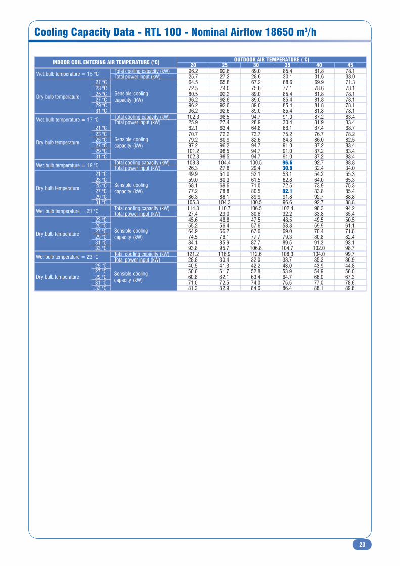
Cooling Capacity Data - RTL 100 - Nominal Airflow 18650 m3/h
INDOOR COIL ENTERING AIR TEMPERATURE (°C) OUTDOOR AIR TEMPERATURE (°C)20 25 30 35 40 45
Wet bulb temperature = 15 °C Total cooling capacity (kW) 96.2 92.6 89.0 85.4 81.8 78.1Total power input (kW) 25.7 27.2 28.6 30.1 31.6 33.0
Dry bulb temperature
21 °C
Sensible coolingcapacity (kW)
64.5 65.8 67.2 68.6 69.9 71.323 °C 72.5 74.0 75.6 77.1 78.6 78.125 °C 80.5 92.2 89.0 85.4 81.8 78.127 °C 96.2 92.6 89.0 85.4 81.8 78.129 °C 96.2 92.6 89.0 85.4 81.8 78.131 °C 96.2 92.6 89.0 85.4 81.8 78.1
Wet bulb temperature = 17 °C Total cooling capacity (kW) 102.3 98.5 94.7 91.0 87.2 83.4Total power input (kW) 25.9 27.4 28.9 30.4 31.9 33.4
Dry bulb temperature
21 °C
Sensible coolingcapacity (kW)
62.1 63.4 64.8 66.1 67.4 68.723 °C 70.7 72.2 73.7 75.2 76.7 78.225 °C 79.2 80.9 82.6 84.3 86.0 82.527 °C 97.2 96.2 94.7 91.0 87.2 83.429 °C 101.2 98.5 94.7 91.0 87.2 83.431 °C 102.3 98.5 94.7 91.0 87.2 83.4
Wet bulb temperature = 19 °C Total cooling capacity (kW) 108.3 104.4 100.5 96.6 92.7 88.8Total power input (kW) 26.3 27.8 29.4 30.9 32.4 34.0
Dry bulb temperature
21 °C
Sensible coolingcapacity (kW)
49.9 51.0 52.1 53.1 54.2 55.323 °C 59.0 60.3 61.5 62.8 64.0 65.325 °C 68.1 69.6 71.0 72.5 73.9 75.327 °C 77.2 78.8 80.5 82.1 83.8 85.429 °C 86.3 88.1 89.9 91.8 92.7 88.831 °C 105.3 104.3 100.5 96.6 92.7 88.8
Wet bulb temperature = 21 °C Total cooling capacity (kW) 114.8 110.7 106.5 102.4 98.3 94.2Total power input (kW) 27.4 29.0 30.6 32.2 33.8 35.4
Dry bulb temperature
23 °C
Sensible coolingcapacity (kW)
45.6 46.6 47.5 48.5 49.5 50.525 °C 55.2 56.4 57.6 58.8 59.9 61.127 °C 64.9 66.2 67.6 69.0 70.4 71.829 °C 74.5 76.1 77.7 79.3 80.8 82.431 °C 84.1 85.9 87.7 89.5 91.3 93.133 °C 93.8 95.7 106.8 104.7 102.0 98.7
Wet bulb temperature = 23 °C Total cooling capacity (kW) 121.2 116.9 112.6 108.3 104.0 99.7Total power input (kW) 28.8 30.4 32.0 33.7 35.3 36.9
Dry bulb temperature
25 °CSensible coolingcapacity (kW)
40.5 41.3 42.2 43.0 43.9 44.827 °C 50.6 51.7 52.8 53.9 54.9 56.029 °C 60.8 62.1 63.4 64.7 66.0 67.331 °C 71.0 72.5 74.0 75.5 77.0 78.633 °C 81.2 82.9 84.6 86.4 88.1 89.8

24
Cooling Capacity Data - RTH 100 - Nominal Airflow 18650 m3/h
Heating Capacity Data - RTH 100
INDOOR COIL ENTERING AIR TEMPERATURE (°C) OUTDOOR AIR TEMPERATURE (°C)20 25 30 35 40 45
Wet bulb temperature = 15 °C Total cooling capacity (kW) 94.5 90.9 87.3 83.8 80.2 76.7Total power input (kW) 24.9 26.3 27.7 29.1 30.5 32.0
Dry bulb temperature
21 °C
Sensible cooling capacity (kW)
63.3 64.6 65.9 67.3 68.6 70.023 °C 71.1 72.6 74.2 75.7 77.2 76.725 °C 79.0 90.5 87.3 83.8 80.2 76.727 °C 94.5 90.9 87.3 83.8 80.2 76.729 °C 94.5 90.9 87.3 83.8 80.2 76.731 °C 94.5 90.9 87.3 83.8 80.2 76.7
Wet bulb temperature = 17 °C Total cooling capacity (kW) 100.4 96.7 93.0 89.3 85.6 81.9Total power input (kW) 25.1 26.5 28.0 29.4 30.9 32.3
Dry bulb temperature
21 °C
Sensible cooling capacity (kW)
61.0 62.2 63.5 64.8 66.1 67.423 °C 69.3 70.8 72.3 73.8 75.2 76.725 °C 77.7 79.4 81.0 82.7 84.3 81.027 °C 95.4 94.4 92.9 89.3 85.6 81.929 °C 99.4 96.7 93.0 89.3 85.6 81.931 °C 100.4 96.7 93.0 89.3 85.6 81.9
Wet bulb temperature = 19 °C Total cooling capacity (kW) 106.3 102.5 98.6 94.8 91.0 87.1Total power input (kW) 25.4 26.9 28.4 29.9 31.4 32.9
Dry bulb temperature
21 °C
Sensible cooling capacity (kW)
49.0 50.1 51.1 52.1 53.2 54.223 °C 57.9 59.2 60.4 61.6 62.9 64.125 °C 66.8 68.3 69.7 71.1 72.5 73.927 °C 75.7 77.4 79.0 80.6 82.2 83.829 °C 84.7 86.5 88.3 90.1 91.0 87.131 °C 103.3 102.4 98.6 94.8 91.0 87.1
Wet bulb temperature = 21 °C Total cooling capacity (kW) 112.6 108.6 104.6 100.5 96.5 92.5Total power input (kW) 26.5 28.1 29.6 31.1 32.7 34.2
Dry bulb temperature
23 °C
Sensible cooling capacity (kW)
44.8 45.7 46.7 47.6 48.6 49.525 °C 54.2 55.4 56.5 57.7 58.8 60.027 °C 63.7 65.0 66.4 67.7 69.1 70.429 °C 73.1 74.7 76.2 77.8 79.3 80.931 °C 82.6 84.3 86.1 87.8 89.6 91.333 °C 92.0 94.0 104.8 102.7 100.1 96.8
Wet bulb temperature = 23 °C Total cooling capacity (kW) 119.0 114.8 110.5 106.3 102.1 97.9Total power input (kW) 27.8 29.4 31.0 32.6 34.2 35.7
Dry bulb temperature
25 °CSensible cooling capacity (kW)
39.7 40.5 41.4 42.2 43.1 43.927 °C 49.7 50.8 51.8 52.9 53.9 55.029 °C 59.7 61.0 62.2 63.5 64.8 66.031 °C 69.7 71.2 72.6 74.1 75.6 77.133 °C 79.7 81.4 83.1 84.8 86.5 88.2
OUTDOOR AIR TEMPERATURE (°C) INDOOR COIL ENTERING AIR TEMPERATURE (°C)18 20 22 24
Dry bulbtemperature
Wet bulbtemperature
Total heating capacity (kW)
Total power input (kW)
Total heating capacity (kW)
Total power input (kW)
Total heating capacity (kW)
Total power input (kW)
Total heating capacity (kW)
Total power input (kW)
-7 -8 65.9 20.7 64.6 21.2 62.9 21.6 60.6 21.9-6 -7 67.4 21.0 66.1 21.5 64.3 21.9 62.0 22.3-5 -6 69.0 21.4 67.6 21.9 65.8 22.3 63.5 22.6-4 -5 70.7 21.8 69.3 22.3 67.4 22.7 65.1 23.0-3 -4 72.5 22.2 71.1 22.7 69.2 23.1 66.8 23.5-2 -3 74.4 22.6 73.0 23.1 71.0 23.5 68.6 23.9-1 -2 76.5 23.1 75.0 23.5 73.0 23.9 70.5 24.30 -1 78.7 23.5 77.2 24.0 75.1 24.4 72.5 24.81 0 81.0 23.9 79.4 24.4 77.3 24.8 74.7 25.22 1 83.4 24.4 81.8 24.9 79.6 25.3 76.9 25.73 2 86.0 24.9 84.3 25.4 82.1 25.8 79.3 26.24 3 88.6 25.3 86.9 25.9 84.6 26.3 81.7 26.75 4 91.4 25.8 89.6 26.4 87.2 26.8 84.3 27.26 5 94.3 26.3 92.5 26.9 90.0 27.4 86.9 27.77 6 97.3 26.8 96.0 27.6 92.9 27.9 89.7 28.38 7 100.5 27.3 98.5 28.0 95.9 28.5 92.6 28.89 8 103.8 27.8 101.7 28.5 99.0 29.0 95.5 29.4
10 9 107.1 28.4 105.0 29.1 102.2 29.6 98.6 30.011 10 110.7 28.9 108.5 29.7 105.5 30.2 101.8 30.612 11 114.3 29.5 112.0 30.3 109.0 30.9 105.1 31.213 12 118.0 30.0 115.7 30.9 112.5 31.5 108.5 31.814 13 121.9 30.6 119.5 31.5 116.2 32.1 112.0 32.415 14 125.9 31.2 123.4 32.2 120.0 32.8 115.7 33.116 15 130.0 31.8 127.4 32.8 123.9 33.5 119.4 33.817 16 134.2 32.4 131.5 33.5 127.9 34.2 123.2 34.418 17 138.6 33.0 135.8 34.2 132.0 34.9 127.1 35.119 18 143.0 33.6 140.2 34.9 136.2 35.6 131.2 35.820 19 147.6 34.2 144.7 35.6 140.6 36.4 135.3 36.5

25
Cooling Capacity Data - RTL 110 - Nominal Airflow 20000 m3/h
INDOOR COIL ENTERING AIR TEMPERATURE (°C) OUTDOOR AIR TEMPERATURE (°C)20 25 30 35 40 45
Wet bulb temperature = 15 °C Total cooling capacity (kW) 108.0 103.9 99.9 95.8 91.7 87.7Total power input (kW) 30.4 32.1 33.8 35.6 37.3 39.0
Dry bulb temperature
21 °C
Sensible coolingcapacity (kW)
72.3 73.9 75.4 76.9 78.5 80.023 °C 81.3 83.1 84.8 86.5 88.3 87.725 °C 90.3 103.5 99.9 95.8 91.7 87.727 °C 108.0 103.9 99.9 95.8 91.7 87.729 °C 108.0 103.9 99.9 95.8 91.7 87.731 °C 108.0 103.9 99.9 95.8 91.7 87.7
Wet bulb temperature = 17 °C Total cooling capacity (kW) 114.8 110.5 106.3 102.1 97.8 93.6Total power input (kW) 30.6 32.4 34.1 35.9 37.7 39.5
Dry bulb temperature
21 °C
Sensible coolingcapacity (kW)
69.7 71.2 72.7 74.1 75.6 77.123 °C 79.3 81.0 82.7 84.4 86.0 87.725 °C 88.9 90.8 92.7 94.6 96.4 92.627 °C 109.1 108.0 106.3 102.1 97.8 93.629 °C 113.6 110.5 106.3 102.1 97.8 93.631 °C 114.8 110.5 106.3 102.1 97.8 93.6
Wet bulb temperature = 19 °C Total cooling capacity (kW) 121.6 117.2 112.8 108.4 104.0 99.6Total power input (kW) 31.0 32.9 34.7 36.5 38.3 40.2
Dry bulb temperature
21 °C
Sensible coolingcapacity (kW)
56.0 57.2 58.4 59.6 60.8 62.023 °C 66.2 67.6 69.1 70.5 71.9 73.325 °C 76.4 78.0 79.7 81.3 82.9 84.627 °C 86.6 88.5 90.3 92.1 94.0 95.829 °C 96.8 98.9 100.9 103.0 104.0 99.631 °C 118.1 117.1 112.8 108.4 104.0 99.6
Wet bulb temperature = 21 °C Total cooling capacity (kW) 128.8 124.2 119.6 115.0 110.3 105.7Total power input (kW) 32.4 34.3 36.1 38.0 39.9 41.8
Dry bulb temperature
23 °C
Sensible coolingcapacity (kW)
51.2 52.3 53.4 54.4 55.5 56.625 °C 62.0 63.3 64.6 65.9 67.3 68.627 °C 72.8 74.3 75.9 77.4 79.0 80.529 °C 83.6 85.4 87.2 88.9 90.7 92.531 °C 94.4 96.4 98.4 100.4 102.4 104.433 °C 105.2 107.4 119.8 117.5 114.4 110.7
Wet bulb temperature = 23 °C Total cooling capacity (kW) 136.0 131.2 126.4 121.6 116.7 111.9Total power input (kW) 34.0 35.9 37.8 39.8 41.7 43.6
Dry bulb temperature
25 °CSensible coolingcapacity (kW)
45.4 46.4 47.3 48.3 49.3 50.227 °C 56.8 58.0 59.2 60.4 61.7 62.929 °C 68.3 69.7 71.2 72.6 74.1 75.531 °C 79.7 81.4 83.1 84.8 86.5 88.233 °C 91.1 93.0 95.0 96.9 98.9 100.8

26
Cooling Capacity Data - RTH 110 - Nominal Airflow 20000 m3/h
Heating Capacity Data - RTH 110
INDOOR COIL ENTERING AIR TEMPERATURE (°C) OUTDOOR AIR TEMPERATURE (°C)20 25 30 35 40 45
Wet bulb temperature = 15 °C Total cooling capacity (kW) 105.7 101.7 97.8 93.8 89.8 85.8Total power input (kW) 29.5 31.2 32.9 34.6 36.3 38.0
Dry bulb temperature
21 °C
Sensible coolingcapacity (kW)
70.8 72.3 73.8 75.3 76.8 78.323 °C 79.6 81.3 83.0 84.7 86.4 85.825 °C 88.4 101.3 97.8 93.8 89.8 85.827 °C 105.7 101.7 97.8 93.8 89.8 85.829 °C 105.7 101.7 97.8 93.8 89.8 85.831 °C 105.7 101.7 97.8 93.8 89.8 85.8
Wet bulb temperature = 17 °C Total cooling capacity (kW) 112.3 108.2 104.0 99.9 95.8 91.6Total power input (kW) 29.8 31.5 33.2 34.9 36.6 38.4
Dry bulb temperature
21 °C
Sensible coolingcapacity (kW)
68.2 69.7 71.1 72.6 74.0 75.523 °C 77.6 79.3 80.9 82.6 84.2 85.925 °C 87.0 88.8 90.7 92.6 94.4 90.727 °C 106.8 105.7 104.0 99.9 95.8 91.629 °C 111.2 108.2 104.0 99.9 95.8 91.631 °C 112.3 108.2 104.0 99.9 95.8 91.6
Wet bulb temperature = 19 °C Total cooling capacity (kW) 119.0 114.7 110.4 106.1 101.8 97.5Total power input (kW) 30.2 32.0 33.7 35.5 37.3 39.1
Dry bulb temperature
21 °C
Sensible coolingcapacity (kW)
54.9 56.0 57.2 58.4 59.5 60.723 °C 64.8 66.2 67.6 69.0 70.3 71.725 °C 74.8 76.4 78.0 79.6 81.2 82.827 °C 84.8 86.6 88.4 90.2 92.0 93.829 °C 94.7 96.8 98.8 100.8 101.8 97.531 °C 115.6 114.6 110.4 106.1 101.8 97.5
Wet bulb temperature = 21 °C Total cooling capacity (kW) 126.0 121.5 117.0 112.5 108.0 103.5Total power input (kW) 31.5 33.3 35.1 37.0 38.8 40.6
Dry bulb temperature
23 °C
Sensible coolingcapacity (kW)
50.1 51.2 52.2 53.3 54.4 55.425 °C 60.7 62.0 63.3 64.5 65.8 67.127 °C 71.2 72.8 74.3 75.8 77.3 78.829 °C 81.8 83.6 85.3 87.0 88.8 90.531 °C 92.4 94.4 96.3 98.3 100.3 102.233 °C 103.0 105.2 117.3 115.0 112.0 108.4
Wet bulb temperature = 23 °C Total cooling capacity (kW) 133.2 128.4 123.7 119.0 114.3 109.5Total power input (kW) 33.0 34.9 36.8 38.7 40.6 42.4
Dry bulb temperature
25 °CSensible coolingcapacity (kW)
44.4 45.4 46.3 47.3 48.2 49.227 °C 55.6 56.8 58.0 59.2 60.4 61.529 °C 66.8 68.2 69.6 71.1 72.5 73.931 °C 78.0 79.6 81.3 83.0 84.6 86.333 °C 89.2 91.1 93.0 94.9 96.8 98.7
OUTDOOR AIR TEMPERATURE (°C) INDOOR COIL ENTERING AIR TEMPERATURE (°C)18 20 22 24
Dry bulbtemperature
Wet bulbtemperature
Total heating capacity (kW)
Total power input (kW)
Total heating capacity (kW)
Total power input (kW)
Total heating capacity (kW)
Total power input (kW)
Total heating capacity (kW)
Total power input (kW)
-7 -8 74.2 24.5 72.7 25.1 70.7 25.5 68.2 25.9-6 -7 75.8 24.9 74.3 25.5 72.3 26.0 69.7 26.4-5 -6 77.6 25.4 76.1 25.9 74.0 26.4 71.4 26.8-4 -5 79.5 25.9 78.0 26.4 75.9 26.9 73.2 27.3-3 -4 81.6 26.3 80.0 26.9 77.8 27.3 75.1 27.8-2 -3 83.8 26.8 82.1 27.4 79.9 27.8 77.2 28.3-1 -2 86.1 27.3 84.4 27.9 82.1 28.3 79.3 28.80 -1 88.5 27.8 86.8 28.4 84.5 28.9 81.6 29.31 0 91.1 28.4 89.3 28.9 87.0 29.4 84.0 29.92 1 93.9 28.9 92.0 29.5 89.6 30.0 86.5 30.43 2 96.7 29.5 94.8 30.0 92.3 30.6 89.2 31.04 3 99.7 30.0 97.8 30.6 95.2 31.2 91.9 31.65 4 102.8 30.6 100.8 31.2 98.1 31.8 94.8 32.26 5 106.1 31.2 104.0 31.8 101.3 32.4 97.8 32.97 6 109.5 31.8 108.0 32.7 104.5 33.1 100.9 33.58 7 113.1 32.4 110.8 33.1 107.9 33.7 104.1 34.29 8 116.7 33.0 114.4 33.8 111.4 34.4 107.5 34.8
10 9 120.5 33.6 118.2 34.5 115.0 35.1 111.0 35.511 10 124.5 34.3 122.0 35.2 118.7 35.8 114.6 36.212 11 128.6 34.9 126.0 35.9 122.6 36.6 118.3 37.013 12 132.8 35.6 130.1 36.6 126.6 37.3 122.1 37.714 13 137.1 36.3 134.4 37.4 130.7 38.1 126.0 38.415 14 141.6 36.9 138.8 38.1 135.0 38.9 130.1 39.216 15 146.2 37.6 143.3 38.9 139.3 39.7 134.3 40.017 16 151.0 38.4 148.0 39.7 143.8 40.5 138.6 40.818 17 155.9 39.1 152.8 40.5 148.5 41.3 143.0 41.619 18 160.9 39.8 157.7 41.3 153.2 42.2 147.6 42.420 19 166.1 40.6 162.7 42.2 158.1 43.1 152.2 43.3
27
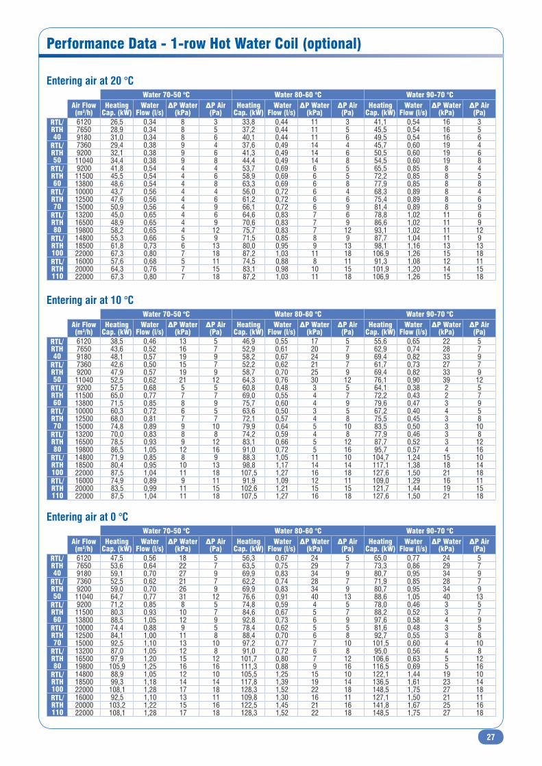
Performance Data - 1-row Hot Water Coil (optional)
Entering air at 20 °C
Entering air at 10 °C
Entering air at 0 °C
Water 70-50 °C Water 80-60 °C Water 90-70 °CAir Flow (m3/h)
HeatingCap. (kW)
WaterFlow (l/s)
ΔP Water (kPa)
ΔP Air(Pa)
HeatingCap. (kW)
WaterFlow (l/s)
ΔP Water (kPa)
ΔP Air (Pa)
HeatingCap. (kW)
WaterFlow (l/s)
ΔP Water (kPa)
ΔP Air (Pa)
RTL/RTH 40
6120 26,5 0,34 8 3 33,8 0,44 11 3 41,1 0,54 16 37650 28,9 0,34 8 5 37,2 0,44 11 5 45,5 0,54 16 59180 31,0 0,34 8 6 40,1 0,44 11 6 49,5 0,54 16 6
RTL/RTH 50
7360 29,4 0,38 9 4 37,6 0,49 14 4 45,7 0,60 19 49200 32,1 0,38 9 6 41,3 0,49 14 6 50,5 0,60 19 611040 34,4 0,38 9 8 44,4 0,49 14 8 54,5 0,60 19 8
RTL/RTH 60
9200 41,8 0,54 4 4 53,7 0,69 6 5 65,5 0,85 8 411500 45,5 0,54 4 6 58,9 0,69 6 5 72,2 0,85 8 513800 48,6 0,54 4 8 63,3 0,69 6 8 77,9 0,85 8 8
RTL/RTH 70
10000 43,7 0,56 4 4 56,0 0,72 6 4 68,3 0,89 8 412500 47,6 0,56 4 6 61,2 0,72 6 6 75,4 0,89 8 615000 50,9 0,56 4 9 66,1 0,72 6 9 81,4 0,89 8 9
RTL/RTH 80
13200 45,0 0,65 4 6 64,6 0,83 7 6 78,8 1,02 11 616500 48,9 0,65 4 9 70,6 0,83 7 9 86,6 1,02 11 919800 58,2 0,65 4 12 75,7 0,83 7 12 93,1 1,02 11 12
RTL/RTH 100
14800 55,3 0,66 5 9 71,5 0,85 8 9 87,7 1,04 11 918500 61,8 0,73 6 13 80,0 0,95 9 13 98,1 1,16 13 1322000 67,3 0,80 7 18 87,2 1,03 11 18 106,9 1,26 15 18
RTL/RTH 110
16000 57,6 0,68 5 11 74,5 0,88 8 11 91,3 1,08 12 1120000 64,3 0,76 7 15 83,1 0,98 10 15 101,9 1,20 14 1522000 67,3 0,80 7 18 87,2 1,03 11 18 106,9 1,26 15 18
Water 70-50 °C Water 80-60 °C Water 90-70 °CAir Flow (m3/h)
HeatingCap. (kW)
WaterFlow (l/s)
ΔP Water (kPa)
ΔP Air(Pa)
HeatingCap. (kW)
WaterFlow (l/s)
ΔP Water (kPa)
ΔP Air (Pa)
HeatingCap. (kW)
WaterFlow (l/s)
ΔP Water (kPa)
ΔP Air (Pa)
RTL/RTH 40
6120 38,5 0,46 13 5 46,9 0,55 17 5 55,6 0,65 22 57650 43,6 0,52 16 7 52,9 0,61 20 7 62,9 0,74 28 79180 48,1 0,57 19 9 58,2 0,67 24 9 69,4 0,82 33 9
RTL/RTH 50
7360 42,6 0,50 15 7 52,2 0,62 21 7 61,7 0,73 27 79200 47,9 0,57 19 9 58,7 0,70 25 9 69,4 0,82 33 911040 52,5 0,62 21 12 64,3 0,76 30 12 76,1 0,90 39 12
RTL/RTH 60
9200 57,5 0,68 5 5 60,8 0,48 3 5 64,1 0,38 2 511500 65,0 0,77 7 7 69,0 0,55 4 7 72,2 0,43 2 713800 71,5 0,85 8 9 75,7 0,60 4 9 79,6 0,47 3 9
RTL/RTH 70
10000 60,3 0,72 6 5 63,6 0,50 3 5 67,2 0,40 4 512500 68,0 0,81 7 7 72,1 0,57 4 8 75,5 0,45 3 815000 74,8 0,89 9 10 79,9 0,64 5 10 83,5 0,50 3 10
RTL/RTH 80
13200 70,0 0,83 8 8 74,2 0,59 4 8 77,9 0,46 3 816500 78,5 0,93 9 12 83,1 0,66 5 12 87,7 0,52 3 1219800 86,5 1,05 12 16 91,0 0,72 5 16 95,7 0,57 4 16
RTL/RTH 100
14800 71,9 0,85 8 9 88,3 1,05 11 10 104,7 1,24 15 1018500 80,4 0,95 10 13 98,8 1,17 14 14 117,1 1,38 18 1422000 87,5 1,04 11 18 107,5 1,27 16 18 127,6 1,50 21 18
RTL/RTH 110
16000 74,9 0,89 9 11 91,9 1,09 12 11 109,0 1,29 16 1120000 83,5 0,99 11 15 102,6 1,21 15 15 121,7 1,44 19 1522000 87,5 1,04 11 18 107,5 1,27 16 18 127,6 1,50 21 18
Water 70-50 °C Water 80-60 °C Water 90-70 °CAir Flow (m3/h)
HeatingCap. (kW)
WaterFlow (l/s)
ΔP Water (kPa)
ΔP Air(Pa)
HeatingCap. (kW)
WaterFlow (l/s)
ΔP Water (kPa)
ΔP Air (Pa)
HeatingCap. (kW)
WaterFlow (l/s)
ΔP Water (kPa)
ΔP Air (Pa)
RTL/RTH 40
6120 47,5 0,56 18 5 56,3 0,67 24 5 65,0 0,77 24 57650 53,6 0,64 22 7 63,5 0,75 29 7 73,3 0,86 29 79180 59,1 0,70 27 9 69,9 0,83 34 9 80,7 0,95 34 9
RTL/RTH 50
7360 52,5 0,62 21 7 62,2 0,74 28 7 71,9 0,85 28 79200 59,0 0,70 26 9 69,9 0,83 34 9 80,7 0,95 34 911040 64,7 0,77 31 12 76,6 0,91 40 13 88,6 1,05 40 13
RTL/RTH 60
9200 71,2 0,85 8 5 74,8 0,59 4 5 78,0 0,46 3 511500 80,3 0,93 10 7 84,6 0,67 5 7 88,2 0,52 3 713800 88,5 1,05 12 9 92,8 0,73 6 9 97,6 0,58 4 9
RTL/RTH 70
10000 74,4 0,88 9 5 78,4 0,62 5 5 81,6 0,48 3 512500 84,1 1,00 11 8 88,4 0,70 6 8 92,7 0,55 3 815000 92,5 1,10 13 10 97,2 0,77 7 10 101,5 0,60 4 10
RTL/RTH 80
13200 87,0 1,05 12 8 91,0 0,72 6 8 95,0 0,56 4 816500 97,9 1,20 15 12 101,7 0,80 7 12 106,6 0,63 5 1219800 105,9 1,25 16 16 111,3 0,88 9 16 116,5 0,69 5 16
RTL/RTH 100
14800 88,9 1,05 12 10 105,5 1,25 15 10 122,1 1,44 19 1018500 99,3 1,18 14 14 117,8 1,39 19 14 136,5 1,61 23 1422000 108,1 1,28 17 18 128,3 1,52 22 18 148,5 1,75 27 18
RTL/RTH 110
16000 92,5 1,10 13 11 109,8 1,30 16 11 127,1 1,50 21 1120000 103,2 1,22 15 16 122,5 1,45 21 16 141,8 1,67 25 1622000 108,1 1,28 17 18 128,3 1,52 22 18 148,5 1,75 27 18

28
Indoor Blower Performance - RoofT@ir 40 & 50 - Standard Fan
40 0
45 0
50 0
60 0
70 0
80 0
90 0
100 0
110 0
120 0
130 0
5
5
6
7
8
10
11
12
13
14
16
S-SC
W
6
7
8
9
11
12
14
15
17
18
20
AR
W
.090
.021
.081
.052
.073
.055
.057
.1 1
.1 5
.2 23
4
.5 5.7 5 11
54 60 67 70 67 58
47
6570
75
80
85
90
95
100
0. 4 0. 5 0. 7 1 1. 4 2 3 4 5 6 7 80
90
10 0
12 0
14 0
18 0
20 0
25 0
30 0
35 0
40 0
50 0
60 0
70 0
80 0
90 0
100 0
120 0
140 0
150 0
Tota
l pre
ssur
eWHEEL DIAMETER 3 93 mm
AT 15-15
AR
S-S C
1. 5 2 3 4 5 6 7 8 9 10 14 20 X 1000
Volume
2 3 4 5 6 7 8 9 10 14 20 30 Air outlet velocity
2 3 4 5 7 10 20 30 50 70 10 0 20 0 30 0 50 0 70 0 Velocity pressure
KW
m3/s
RPM
a P
m2
/ N
Impeller total eff. %
m3/h
m/s
Pa N/m2
LW(A) in dB(A)
ρ = 1.2 Kg / m3
Bear
ing
pow
er
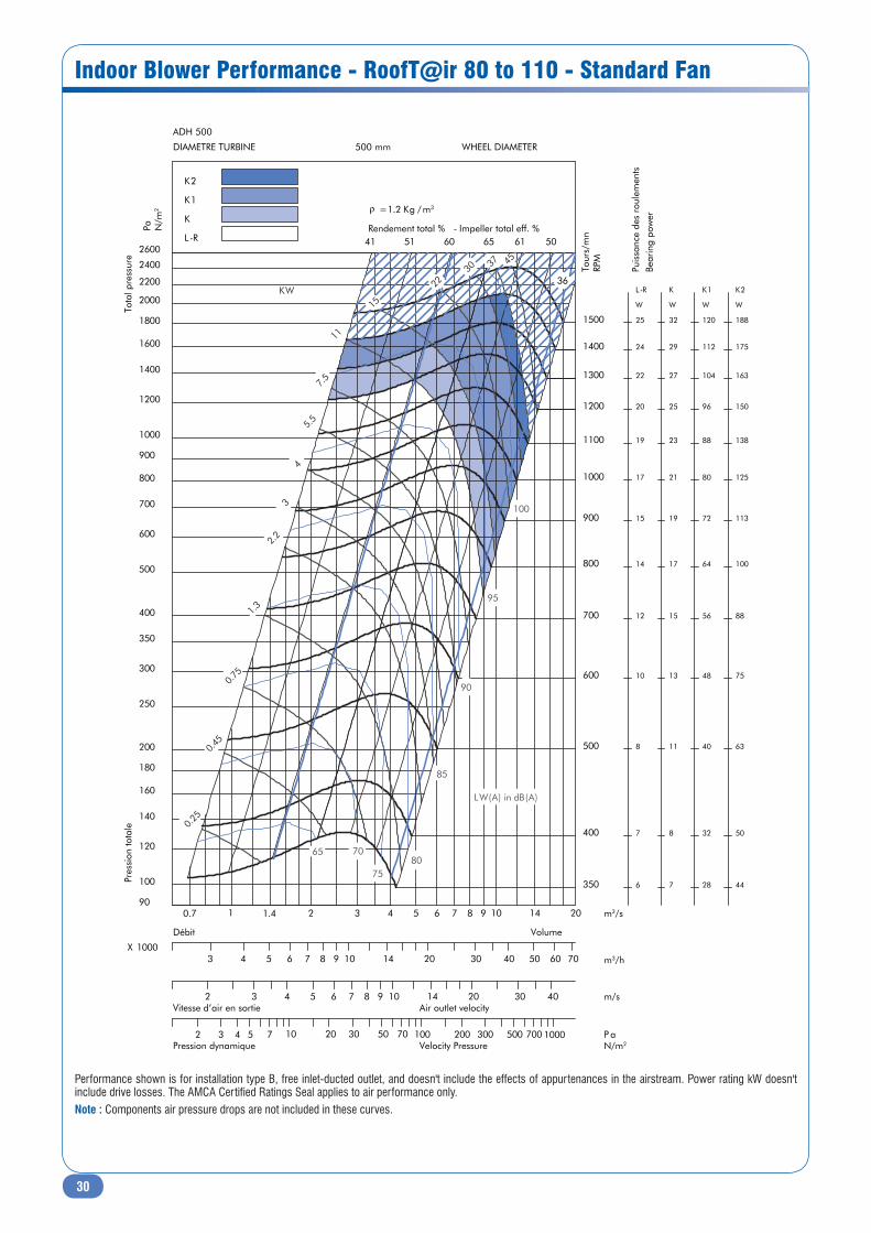
Performance shown is for installation type B, free inlet-ducted outlet, and doesn't include the effects of appurtenances in the airstream. Power rating kW doesn't include drive losses. The AMCA Certified Ratings Seal applies to air performance only.Note : Components air pressure drops are not included in these curves.

29
Indoor Blower Performance - RoofT@ir 60 & 70 - Standard Fan
3 5 0
4 0 0
5 0 0
6 0 0
7 0 0
8 0 0
9 0 0
1 0 0 0
1 1 0 0
1 2 0 0
1 3 0 0
1 4 0 0
1 5 0 0
1 6 0 0
6
7
8
1 0
1 2
1 4
1 5
1 7
1 9
2 0
2 2
2 4
2 5
2 7
L - R
W
7
8
1 1
1 3
1 5
1 7
1 9
2 1
2 3
2 5
2 7
2 9
3 2
3 4
K
W
2 8
3 2
4 0
4 8
5 6
6 4
7 2
8 0
8 8
9 6
1 0 4
1 1 2
1 2 0
1 2 8
K 1
W
0.18
0.37
0.75
1.1
1.5
2.2
3
4
5.5
7.5
11
15
2230 37
4 0 4 9 5 8 6 3 5 9 4 8
3 6
6570
75
80
85
90
95
100
0 . 5 0 . 7 1 1 . 4 2 3 4 5 6 7 8 9 1 0 1 2 1 6 7 0
8 0
9 0
1 0 0
1 2 0
1 4 0
1 6 0
1 8 0
2 0 0
2 5 0
3 0 0
3 5 0
4 0 0
5 0 0
6 0 0
7 0 0
8 0 0
9 0 0
1 0 0 0
1 2 0 0
1 4 0 0
1 6 0 0
1 8 0 0
2 0 0 0
2 2 0 0
2 4 0 0
2 6 0 0
RPM
Tota
l pre
ssur
eWHEEL DIAMETER 4 5 0 m m
A D H 4 5 0
K 1
K
L - R
2 3 4 5 6 7 8 9 1 0 1 4 2 0 3 0 4 0 5 0 X 1 0 0 0
Volume
2 3 4 5 6 7 8 9 1 0 1 4 2 0 3 0 4 0 Air outlet velocity
2 3 4 5 7 1 0 2 0 3 0 5 0 7 0 1 0 0 2 0 0 3 0 0 5 0 0 7 0 0 1 0 0 0 Velocity pressure
KW
m3/s
P a
N / m
2
Impeller total eff. %
m3/h
m/s
P a N / m2
LW(A) in dB(A)
r = 1 . 2 K g / m3
Bear
ing
pow
er
Performance shown is for installation type B, free inlet-ducted outlet, and doesn't include the effects of appurtenances in the airstream. Power rating kW doesn't include drive losses. The AMCA Certified Ratings Seal applies to air performance only.Note : Components air pressure drops are not included in these curves.
30
Indoor Blower Performance - RoofT@ir 80 to 110 - Standard Fan
350
400
500
600
700
800
900
1000
1100
1200
1300
1400
1500
6
7
8
10
12
14
15
17
19
20
22
24
25
L-R
W
7
8
11
13
15
17
19
21
23
25
27
29
32
K
W
28
32
40
48
56
64
72
80
88
96
104
112
120
K1
W
44
50
63
75
88
100
113
125
138
150
163
175
188
K2
W
0.25
0.45
0.75
1.3
2.2
3
4
5.5
7.5
11
15
2230 37 45
41 51 60 65 61 50
36
65 70
7580
85
90
95
100
0.7 1 1.4 2 3 4 5 6 7 8 9 10 14 2090
100
120
140
160
180
200
250
300
350
400
500
600
700
800
900
1000
1200
1400
1600
1800
2000
2200
2400
2600
Tour
s/m
nRP
M
Pres
sion
tota
leTo
tal p
ress
ure
DIAMETRE TURBINE WHEEL DIAMETER500 mm
ADH 500
K2
K1
K
L-R
3 4 5 6 7 8 9 10 14 20 30 40 50 60 70X 1000
Débit Volume
2 3 4 5 6 7 8 9 10 14 20 30 40Vitesse d’air en sortie
2 3 4 5 7 10 20 30 50 70 100 200 300 500 700 1000Pression dynamique
Air outlet velocity
Velocity Pressure
KW
m3/s
m3/h
Pa N/m
2
Rendement total % - Impeller total eff. %
m/s
P aN/m2
LW(A) in dB(A)
ρ =1.2 Kg /m3
Puis
sanc
e de
s ro
ulem
ents
Bear
ing
pow
er
Performance shown is for installation type B, free inlet-ducted outlet, and doesn't include the effects of appurtenances in the airstream. Power rating kW doesn't include drive losses. The AMCA Certified Ratings Seal applies to air performance only.Note : Components air pressure drops are not included in these curves.

31
Indoor Blower Performance - RoofT@ir 40 & 50 - High Pressure Fan (optional)
40 0
45 0
50 0
60 0
70 0
80 0
90 0
100 0
110 0
120 0
130 0
5
5
6
7
8
10
11
12
13
14
16
S-SC
W
6
7
8
9
11
12
14
15
17
18
20
AR
W
.090
.021
.081
.052
.073
.055
.057
.1 1
.1 5
.2 23
4
.5 5.7 5 11
54 60 67 70 70 67 58
47
6570
75
80
85
90
95
100
0. 4 0. 5 0. 7 1 1. 4 2 3 4 5 6 7 80
90
10 0
12 0
14 0
18 0
20 0
25 0
30 0
35 0
40 0
50 0
60 0
70 0
80 0
90 0
100 0
120 0
140 0
150 0
E L A
T
O
T N
O
I
S S
E R
P S
E R
P L A
T
O
T E
R U
S
3 93 mm
AT 15-15 DIAMETRE TURBINE WHEEL DIAMETER
AR
S-S C
1. 5 2 3 4 5 6 7 8 9 10 14 20 X 1000
Volume Débit
2 3 4 5 6 7 8 9 10 14 20 30 Vitesse d’air en sortie Air outlet velocity
2 3 4 5 7 10 20 30 50 70 10 0 20 0 30 0 50 0 70 0 Pression dynamique Velocity Pressure
KW
m3/s
tr/m
n M
P R
a P
m2
/ N
RENDEMENT TOTAL % - IMPELLER TOTAL EFF. %
m3/h
m/s
Pa N/m2
LW(A) in dB(A)
r = 1.2 Kg / m3
Puis
sanc
e de
s ro
ulem
ents
R
E W
O
P
G
N
I R
A
E B
Performance shown is for installation type B, free inlet-ducted outlet, and doesn't include the effects of appurtenances in the airstream. Power rating kW doesn't include drive losses. The AMCA Certified Ratings Seal applies to air performance only.Note : Components air pressure drops are not included in these curves.
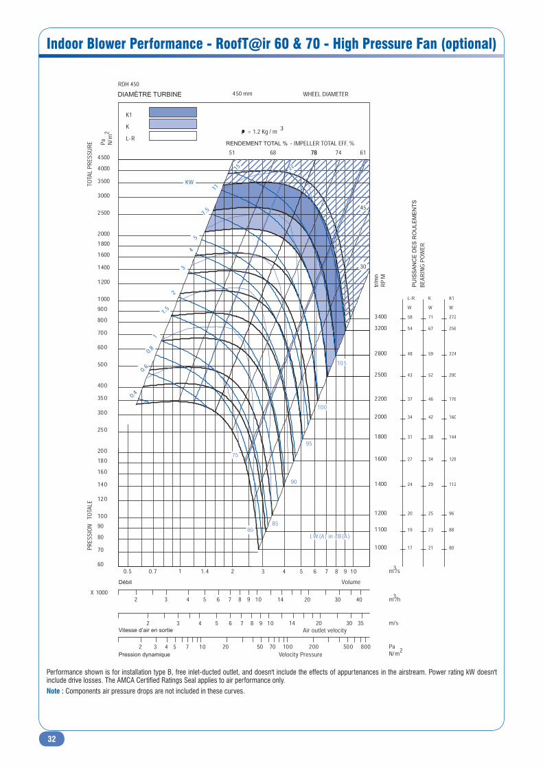
32
Indoor Blower Performance - RoofT@ir 60 & 70 - High Pressure Fan (optional)
DIAMÈTRE TURBINE
RENDEMENT TOTAL %
tr/m
n
PU
ISS
AN
CE
DE
S R
OU
LEM
EN
TS
Débit
Vitesse d’air en sortie
Pression dynamique
Performance shown is for installation type B, free inlet-ducted outlet, and doesn't include the effects of appurtenances in the airstream. Power rating kW doesn't include drive losses. The AMCA Certified Ratings Seal applies to air performance only.Note : Components air pressure drops are not included in these curves.
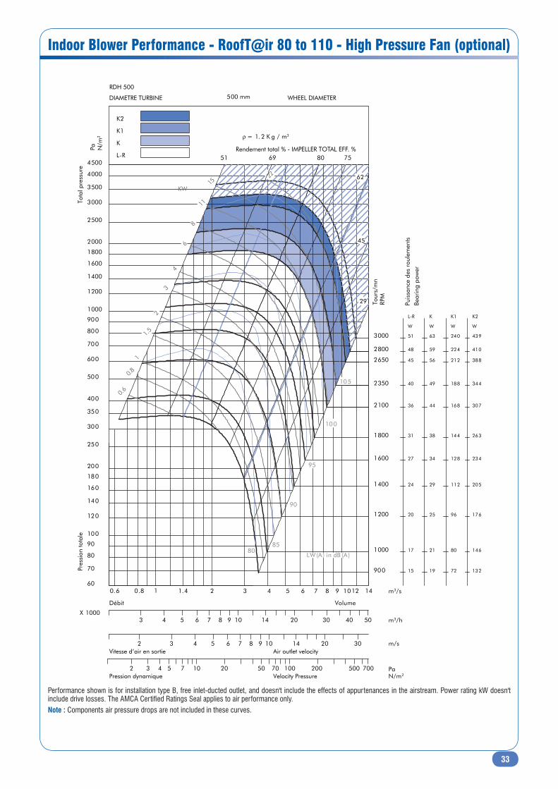
33
Indoor Blower Performance - RoofT@ir 80 to 110 - High Pressure Fan (optional)
Rendement total % - IMPELLER TOTAL EFF. %
900
1000
1200
1400
1600
1800
2100
2350
2650
2800
3000
15
17
20
24
27
31
36
40
45
48
51
L-R
W
19
21
25
29
34
38
44
49
56
59
63
K
W
72
80
96
112
128
144
168
188
212
224
240
K1
W
132
146
176
205
234
263
307
344
388
410
439
K2
W
6.0
8.0
1
1.5
2
3
4
6
8
11
5122
51 69 80 75
62
45
29
8085
90
95
100
105
0.6 0.8 1 1.4 2 3 4 5 6 7 8 9 1012 1460
70
80
90
100
120
140
160
180
200
250
300
350
400
500
600
700
800
900
1000
1200
1400
1600
1800
2000
2500
3000
3500
4000
4500
500 mm
RDH 500
K2
K1
K
L-R
X 10003
2
2 3 4 5 7 10 20 50 70 100 200 500 700
3 4 5 6 7 8 9 10 14 20 30
4 5 6 7 8 9 10 14 20 30 40 50
KW
m3/s
m3/h
m/s
N/m2
Pa N/m
2
Pa
LW (A) in dB (A)
ρ = 1.2 K g / m3
Tour
s/m
nRP
M
Pres
sion
tota
leTo
tal p
ress
ure
DIAMETRE TURBINE WHEEL DIAMETER
VolumeDébit
Pression dynamique Velocity Pressure
Vitesse d’air en sortie Air outlet velocity
Puis
sanc
e de
s ro
ulem
ents
Bear
ing
pow
er
Performance shown is for installation type B, free inlet-ducted outlet, and doesn't include the effects of appurtenances in the airstream. Power rating kW doesn't include drive losses. The AMCA Certified Ratings Seal applies to air performance only.Note : Components air pressure drops are not included in these curves.
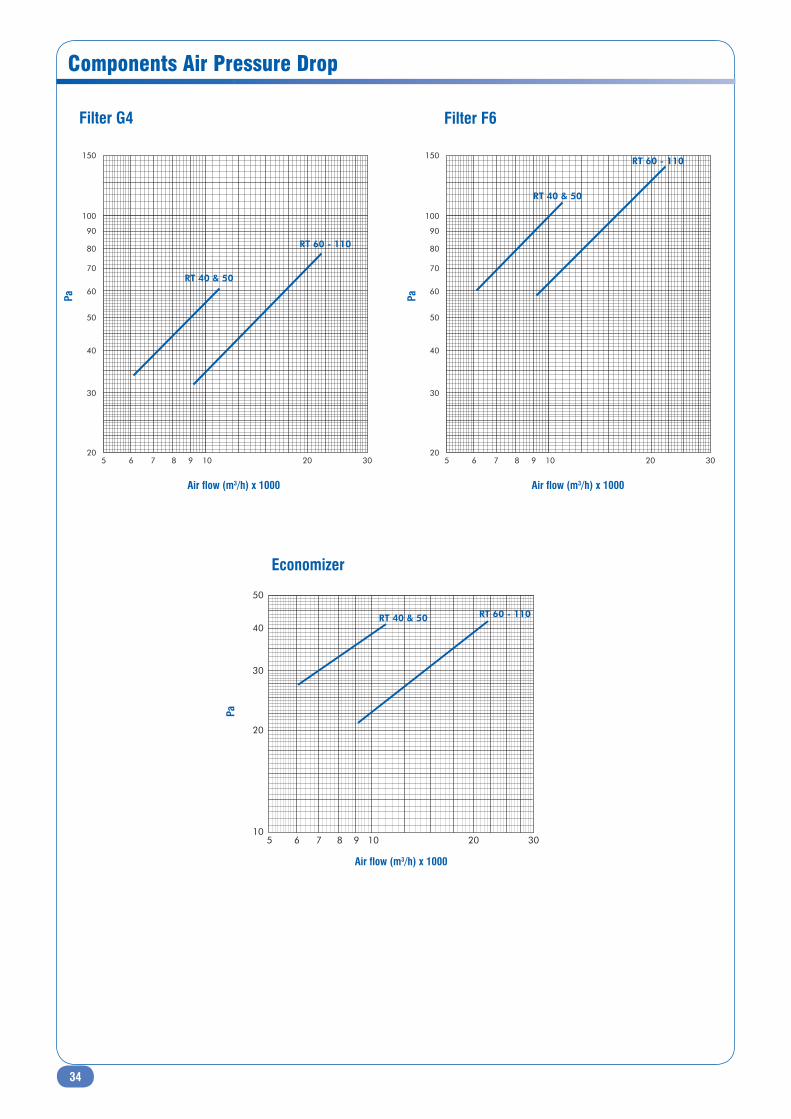
34
Components Air Pressure Drop
Filter G4 Filter F6
Economizer
Air flow (m3/h) x 1000
Air flow (m3/h) x 1000
Air flow (m3/h) x 1000
Pa
Pa
Pa
10
20
30
40
50
20 305 6 7 8 9 10
RT 60 - 110RT 40 & 50
20
150
30
40
50
60
70
80
90
100
20 305 6 7 8 9 10
RT 60 - 110
RT 40 & 50
20
150
30
40
50
60
70
80
90
100
20 305 6 7 8 9 10
RT 60 - 110
RT 40 & 50
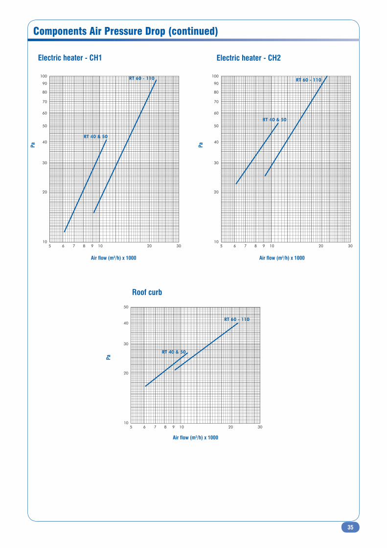
35
Components Air Pressure Drop (continued)
Electric heater - CH1 Electric heater - CH2
Roof curb
Air flow (m3/h) x 1000
Air flow (m3/h) x 1000
Air flow (m3/h) x 1000
Pa Pa
Pa
10
20
30
40
50
60
70
80
90
100
20 305 6 7 8 9 10
RT 60 - 110
RT 40 & 50
10
20
30
40
50
60
70
80
90
100
20 305 6 7 8 9 10
RT 60 - 110
RT 40 & 50
10
20
30
40
50
20 305 6 7 8 9 10
RT 60 - 110
RT 40 & 50
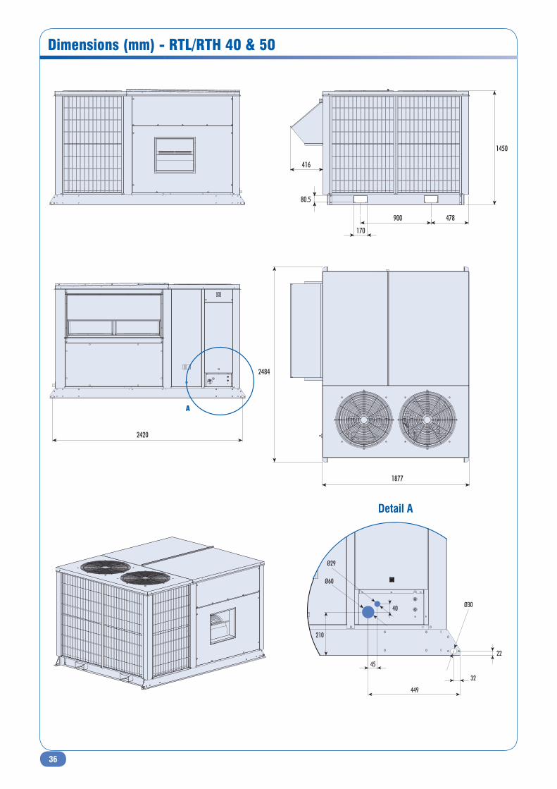
36
Dimensions (mm) - RTL/RTH 40 & 50
449
32
22
45
Ø60
Ø29
210
40 Ø30
Detail A
416
170
900
80.5
478
1450
2420
A
1877
2484
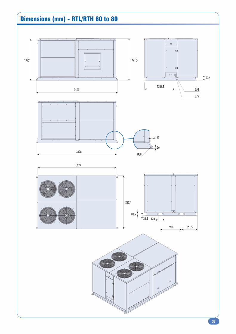
37
Dimensions (mm) - RTL/RTH 60 to 80
1771.5
3328
36
36
Ø30
3400
1747
3277
2227
900
17031.580.5
651.5
232
1266.5Ø53
Ø75
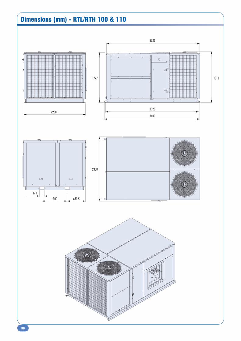
38
Dimensions (mm) - RTL/RTH 100 & 110
2200 3328
3400
900 651.5
170
1777
2308
1813
3326
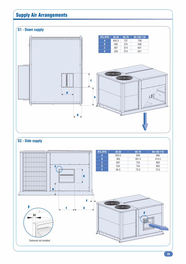
39
Supply Air Arrangements
S1 - Down supply
S2 - Side supply
C
A
D
B
C A
E
B
F
D
RTL/RTH 40-50 60-70 80-100-110A 645.5 737 738B 295 375 358C 497 574 641D 430 574 641
RTL/RTH 40-50 60-70 80-100-110A 593.5 658 660B 365 391.5 414.5C 601 734 803D 534 734 803E 65.5 73.5 73.5
F
F
51
Delivered not installed
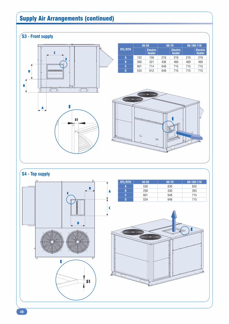
40
Supply Air Arrangements (continued)
RTL/RTH40-50 60-70 80-100-110
Electricheater
Electricheater
Electricheater
A 122 158 219 219 219 219B 360 321 436 460 460 460C 601 714 648 715 715 715D 534 612 648 715 715 715
S3 - Front supply
S4 - Top supply
C
E
D
A
B
C
AB
E
D
RTL/RTH 40-50 60-70 80-100-110A 530 630 632B 258 330 263C 601 648 715D 534 648 715
E
E
51
E
51
E
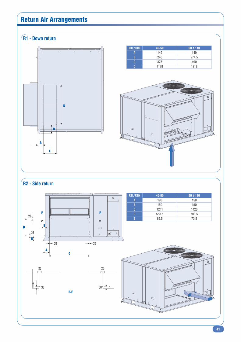
41
Return Air Arrangements
R1 - Down return
C
A
B
D
R2 - Side return
RTL/RTH 40-50 60 à 110A 149 149B 246 274.5C 375 490D 1139 1318
RTL/RTH 40-50 60 à 110A 195 150B 150 150C 1241 1420D 553.5 703.5E 65.5 73.5
D E
20
28
20
20
20
30 30
20
F F
B
AC
F-F

42
Return Air Arrangements (continued)
R3 - Front return
R4 - Top return
DB
A
C
RTL/RTH 40-50 60 à 110A 90 100B 150 150C 412 514.5D 982 1352
RTL/RTH 40-50 60 à 110A 180 180B 180 180C 1139 1359D 439 532
E
26 E
A
B
DEE
E-E
C
28
20
20
20 20
3030
20
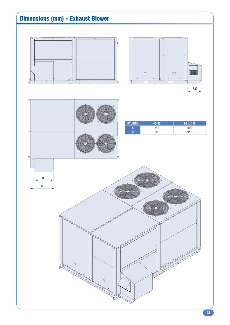
43
Dimensions (mm) - Exhaust Blower
532
A
B
RTL/RTH 40-50 60 to 110A 642 690B 828 910
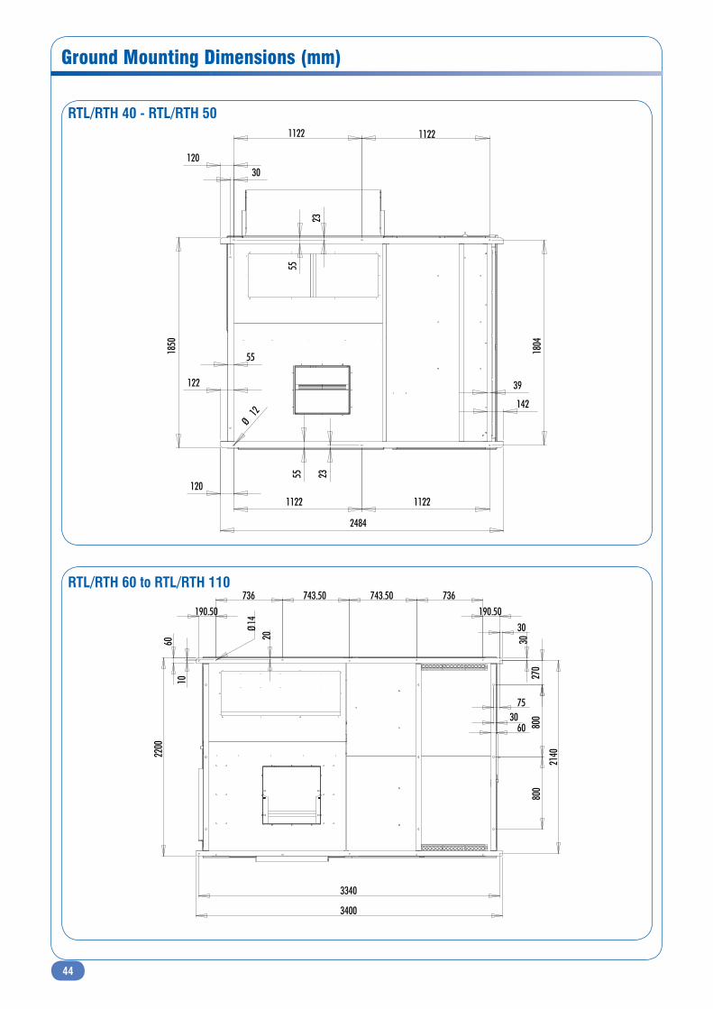
44
Ground Mounting Dimensions (mm)
1122 1122
1122 1122
55
120
30120
55
23
55 23
248418
04
Ø12
39
142
122
1850
800
800
270
30
75
30
2140
190.50736743.50743.50736
Ø14190.50
10
20
3340
6030
60
3400
2200
RTL/RTH 40 - RTL/RTH 50
RTL/RTH 60 to RTL/RTH 110
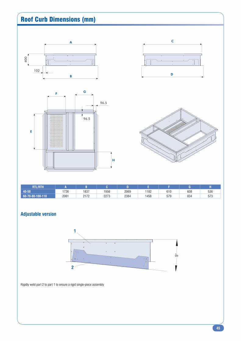
45
Roof Curb Dimensions (mm)
Adjustable version
GF
96.5
96.5
400
A
102
B
C
D
H
E
RTL/RTH A B C D E F G H40-50 1726 1837 1956 2069 1182 610 608 53660-70-80-100-110 2061 2172 2273 2384 1458 579 834 573
5°
1
2
Rigidly weld part 2 to part 1 to ensure a rigid single-piece assembly
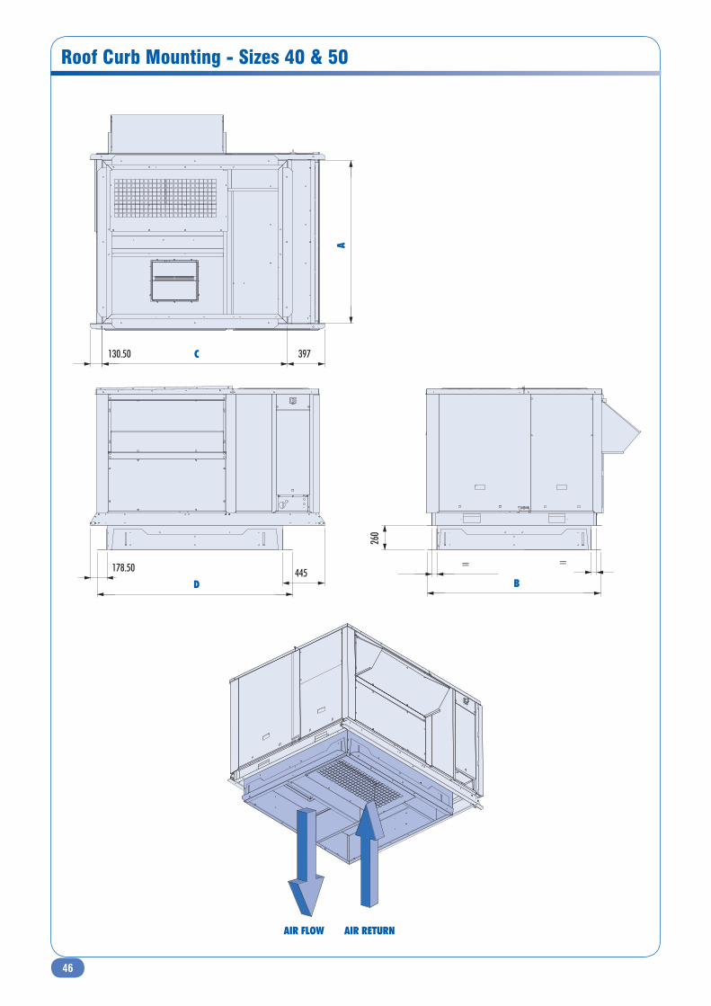
46
Roof Curb Mounting - Sizes 40 & 50
445 178.50
D
AC130.50 397
B
260
= =
AIR FLOW AIR RETURN
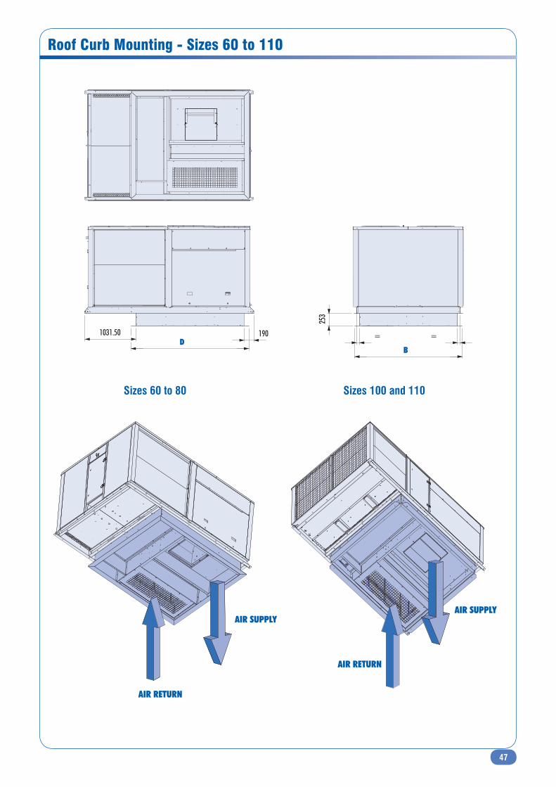
47
Roof Curb Mounting - Sizes 60 to 110
= =
B
253
D1031.50 190
Sizes 60 to 80 Sizes 100 and 110
AIR RETURN
AIR SUPPLY
AIR RETURN
AIR SUPPLY
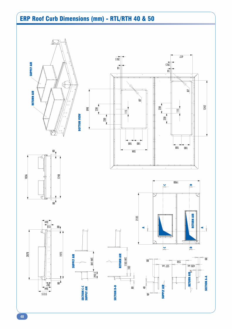
48
ERP Roof Curb Dimensions (mm) - RTL/RTH 40 & 50
SUPP
LY A
IR
SUPP
LY A
IRRE
TURN
AIR
80
512.5
1975
80
2078
364
364 153
207
1900
2135
RETU
RN A
IR
80
1740
80
1836
80 80
527 int. 420 int.
48
48
72
550
SECT
ION
A-A
SUPP
LY A
IR RETU
RN A
IR
293.5
84
1 INT
.
SECT
ION
C-C
SUPP
LY A
IR
80
103 11
85 IN
T.
SECT
ION
D-D
RETU
RN A
IR
115
115 89
8
584
477
1242
230
230
180 180
28.5
18
28.5
18
230
230
180 180
Ø7
Ø7
BOTT
OM V
IEW
A A
CC
DD
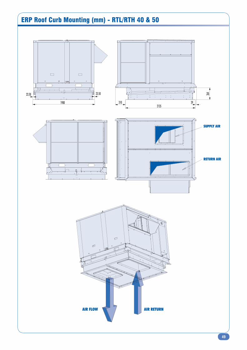
49
ERP Roof Curb Mounting (mm) - RTL/RTH 40 & 50
364
310 2135
39
23.50 23.50
1900
SUPPLY AIR
RETURN AIR
AIR FLOW AIR RETURN

50
ERP Roof Curb Dimensions (mm) - RTL/RTH 60 to 110
SUPP
LY A
IR
RETU
RN A
IR
372 78.50
522
80
2297
2400
2457
2240
TOP
VIEW
115
115
28.50
18
544
1432
531.50
1147
28.50
28.50 18
Ø 7
180 180
230
230
180 180
230
Ø 7
DOW
N VI
EW
AIR
SUPP
LY
RETU
RN A
IR
243
1090
int.
SECT
ION
D-D
110
1375
int.
SECT
ION
E-E
SUPP
LY A
IR
RETU
RN A
IR
SUPP
LY A
IRRE
TURN
AIR
80
211
487 int.
414
474.50 int.
80
48
48
SECT
ION
G-G
SUPP
LY A
IR
RETU
RN A
IR
80
2080
80
2176
A A
DD
EE
G
GG

51
ERP Roof Curb Dimensions (mm) - RTL/RTH 60 to 110
Sizes 60 to 80 Sizes 100 and 110
372
2457 52.5
890.5
2240
18.50 18.50
SUPPLY AIR
RETURN AIR
AIR FLOW AIR RETURN
AIR FLOWAIR RETURN
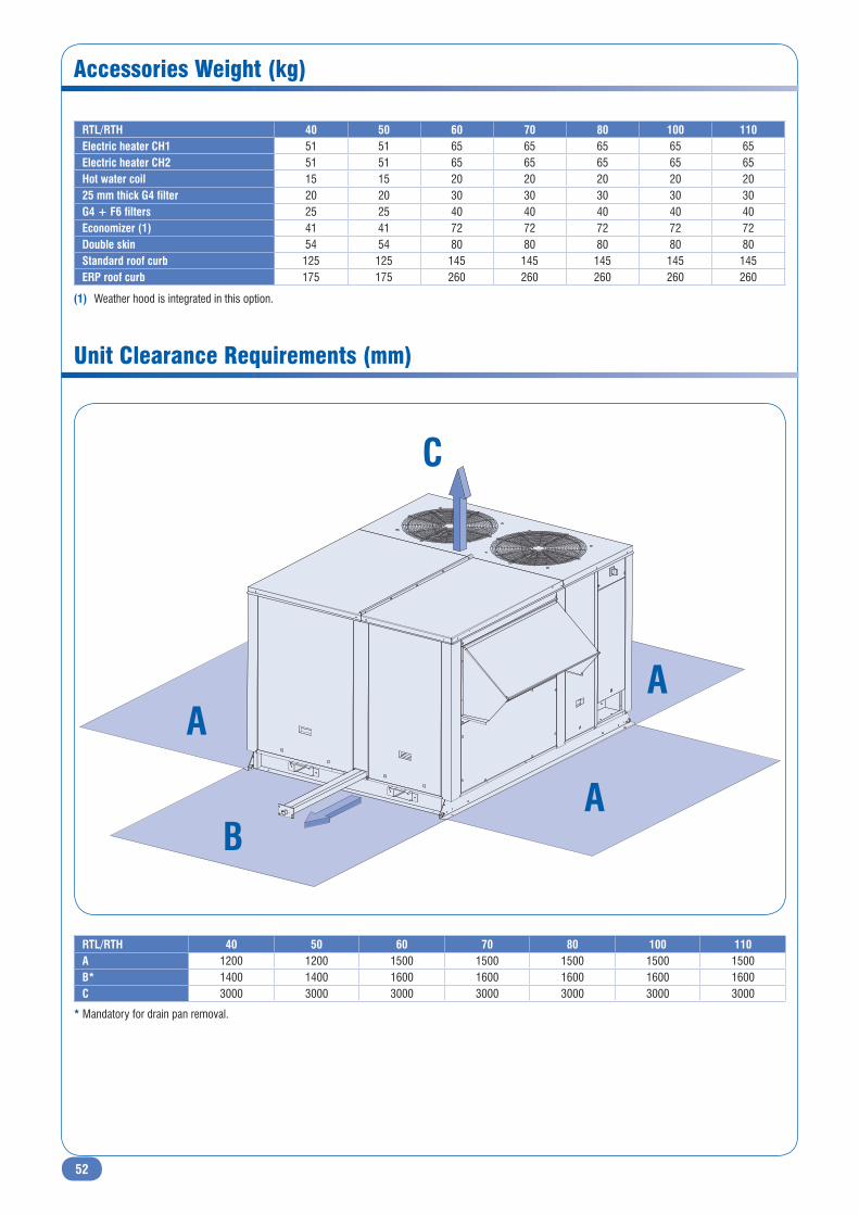
52
Accessories Weight (kg)
B
A
A
A
C
RTL/RTH 40 50 60 70 80 100 110A 1200 1200 1500 1500 1500 1500 1500B* 1400 1400 1600 1600 1600 1600 1600C 3000 3000 3000 3000 3000 3000 3000
* Mandatory for drain pan removal.
Unit Clearance Requirements (mm)
RTL/RTH 40 50 60 70 80 100 110Electric heater CH1 51 51 65 65 65 65 65Electric heater CH2 51 51 65 65 65 65 65Hot water coil 15 15 20 20 20 20 2025 mm thick G4 filter 20 20 30 30 30 30 30G4 + F6 filters 25 25 40 40 40 40 40Economizer (1) 41 41 72 72 72 72 72Double skin 54 54 80 80 80 80 80Standard roof curb 125 125 145 145 145 145 145ERP roof curb 175 175 260 260 260 260 260
(1) Weather hood is integrated in this option.

53
Specification Guide
GENERAL
• The rooftop shall be manufactured in factory certificated ISO 9001:2000 and shall be compliant to PED-97-23 and EN-60204-1.
• The rooftop shall be RoofT@ir or equivalent.
• The rooftop shall be designed for outdoor use and roof curb application.
• Pre-assembled in one single package fully tested at the factory.
CASING
• All panels exposed to the weather shall be manufactured of galvanized steel, painted with RAL 9001 to withstand salt spray test ISO-9227 and NFT-30077.
• The base rail shall provide two slots for fork transport and 4 points for lifting.
• Unit base shall be compatible with a roof curb manufactured by the same provider.
• All side panels of the treated air shall be at least insulated with 25 mm non-flammable and non-hygroscopic 62 kg/m3 fibreglass insulation. The insulation shall not be glued, but only supported by galvanized steel U-shape stiffeners. Double wall panel shall be optional to improve interior’s cleanness and air quality.
• All panels attached with quarter-turn latches shall be removable for easing components’ services.
REFRIGERANT CIRCUIT
• The refrigerant circuit shall be charged with R410A at the factory. The refrigerant piping, the indoor and outdoor coil headers, compressors and all refrigerant devices shall be located in the same compartment, with a reduced number of soldered joints. The high and low refrigerant pressure taps shall be accessible from outside of the casing to not disturb unit operation.
• Rooftop shall have at least 2 compressors for multistage operation.
• For heat pump, each refrigerant circuit shall be reversible and equipped with four-way valve, bi-flow thermostatic expansion valve, bi-flow filter-drier, sight glass and high/low pressure switches.
• The indoor and outdoor coils shall be made of copper tubes mechanically expanded into aluminium fins. The coils shall be tested at the factory at 42 bars.
• The condensate drain pan under the indoor coil shall be constructed with a slope, and shall be removable for cleaning.
MAIN BLOWER
• The main blower shall consist of centrifugal forward curved fan with double inlets, dynamically and statically balanced in compliance with VDI 2060 standards.
• The drive shall be of the belted pulley type.
• A flexible connector inside the unit and mounted on a removable frame, shall provide the link between the fan/motor assembly and the end of the panel.
• The minimum motor insulation class shall be IP55 in compliance with EN 60529 (IK08 in compliance with EN 50102). They shall have a minimum coefficient of efficiency of EFF2 in accordance with CEMEP criteria.
• The mechanical adjustment of the Fan/Motor assembly (belt tension)
shall be by way of a single piece sliding platform adjustable by a single
screw, without having to slacken the motor mounting. Thus, motor
alignment shall remain fixed.
• As standard equipment, Fan/Motor assembly shall be mounted on rubber
vibration-absorbing pads. This assembly shall not rest directly on the
floor panel but shall rest on an intermediate base frame comprising at
least 2 main cross members in order to spread the load generated by the
Fan / Motor assembly in a even manner.
• 4 different configurations possible for supply and return air flow.
Option : Backward curved blades shall be used for high external static
pressure application.
Option : Differential pressure switch shall be provided to measure air pressure
difference at the inlet and the outlet of the blower.
ELECTRICAL PANEL AND CONTROLS
• Automation and controls shall be assembled and wired at the factory in a
waterproof compartment isolated from the air steam, in compliance with
EN-60204-1. All internal cables and wires shall be identified. A lockable
main disconnect switch shall be operable without touching the casing.
Rooftop shall have only one power switch whatever the options.
• The unit shall be controlled by a regulation module programmed at the
factory to control heating-cooling, ambient temperature setting and
control, compressor cycling and rotation, defrost cycling, overload
protection of motors, high-low pressure as well as winter-summer
ambient temperature compensation, and setting point. The controller
shall store at least 150 failures.
Option : The installation shall be supplied with a communication system
permitting to monitor until 31 units, to centralize and coordinate all units by
one user-interface.
Option : The controller shall be equipped with a RS-485 Interface to allow
for remote supervision, servicing and communication via ModBUS, from the
Building Management System.
ROOF CURB
The roof curb shall be supplied by the manufacturer :
• Roof curb shall be adjustable for a roof slope up to 5° with a return air
plenum. To avoid noise transmission under the compressors, it shall be
insulated.
• Roof curb shall be ERP type to allow air circulation between unit and
building. It shall be compliant with article CH40 of the French building
regulation.
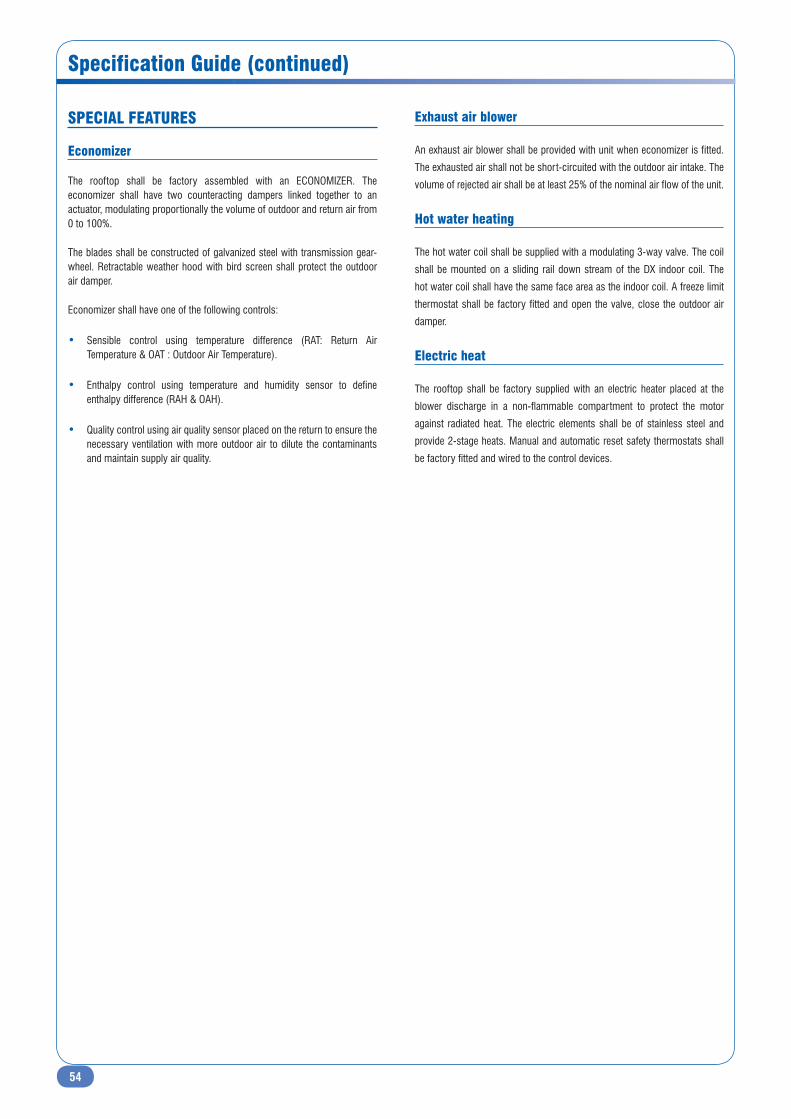
54
Specification Guide (continued)
SPECIAL FEATURES
Economizer
The rooftop shall be factory assembled with an ECONOMIZER. The economizer shall have two counteracting dampers linked together to an actuator, modulating proportionally the volume of outdoor and return air from 0 to 100%.
The blades shall be constructed of galvanized steel with transmission gear-wheel. Retractable weather hood with bird screen shall protect the outdoor air damper.
Economizer shall have one of the following controls:
• Sensible control using temperature difference (RAT: Return Air Temperature & OAT : Outdoor Air Temperature).
• Enthalpy control using temperature and humidity sensor to define enthalpy difference (RAH & OAH).
• Quality control using air quality sensor placed on the return to ensure the necessary ventilation with more outdoor air to dilute the contaminants and maintain supply air quality.
Exhaust air blower
An exhaust air blower shall be provided with unit when economizer is fitted.
The exhausted air shall not be short-circuited with the outdoor air intake. The
volume of rejected air shall be at least 25% of the nominal air flow of the unit.
Hot water heating
The hot water coil shall be supplied with a modulating 3-way valve. The coil
shall be mounted on a sliding rail down stream of the DX indoor coil. The
hot water coil shall have the same face area as the indoor coil. A freeze limit
thermostat shall be factory fitted and open the valve, close the outdoor air
damper.
Electric heat
The rooftop shall be factory supplied with an electric heater placed at the
blower discharge in a non-flammable compartment to protect the motor
against radiated heat. The electric elements shall be of stainless steel and
provide 2-stage heats. Manual and automatic reset safety thermostats shall
be factory fitted and wired to the control devices.
55
Notes
Ref.
: EDM
RTL
H-A.
5GB/
03.1
0 - S
uper
sede
s : E
DM R
TLH-
A.4G
B/10
.08
As p
art o
f our
ong
oing
pro
duct
impr
ovem
ent p
rogr
amm
e, o
ur p
rodu
cts
are
subj
ect t
o ch
ange
with
out p
rior n
otic
e. N
on c
ontra
ctua
l pho
tos.
AIRWELL France SAS1bis, Avenue du 8 mai 1945Saint Quentin en Yvelines78284 GUYANCOURTFranceTel. +33 (0) 01 39 44 78 00Fax +33 (0) 01 39 44 65 17
AN AIRWELL GROUP COMPANY