room air conditioner -...
TRANSCRIPT
LG RoomAir ConditionerSERVICE MANUAL
LG
CAUTION
website http://www.lgservice.com
• BEFORE SERVICING THE UNIT, READ THE SAFETY PRECAUTIONS IN THIS MANUAL.
• ONLY FOR AUTHORIZED SERVICE PERSONNEL.
MODEL: LWHD8000R,LWHD8000RY5,LWHD1000R,LWHD8000RY6
2 Room Air Conditioner
Air Conditioner Service Manual
TABLE OF CONTENTSSafety Precautions..........................................................................................................................................3
Dimensions .....................................................................................................................................................6Outside Dimensions ...................................................................................................................................6
Product Specifications ..................................................................................................................................7
Installation .......................................................................................................................................................8Select the Best Location ............................................................................................................................8
Installation Check .......................................................................................................................................8
How to Secure the Drain Pipe ....................................................................................................................8
How to Install..............................................................................................................................................9
Operation ......................................................................................................................................................12
Function of Controls .................................................................................................................................12
Disassembly ..................................................................................................................................................13
Mechanical Parts......................................................................................................................................13
Air handling Parts .....................................................................................................................................14
Electrical Parts .........................................................................................................................................15
Refrigerating Cycle...................................................................................................................................17
Schematic Diagram .......................................................................................................................................20
Electronic Control Device. ........................................................................................................................20
Wiring Diagram.........................................................................................................................................21
Components Location ..............................................................................................................................22
Troubleshooting Guide .................................................................................................................................23
Pipeing System ........................................................................................................................................23
Troubleshooting Guide .............................................................................................................................24
Electrical Parts Troubleshooting Guide ....................................................................................................26
Electrical Parts .........................................................................................................................................30
Exploded View ..............................................................................................................................................36
Replacement Parts List ................................................................................................................................37
Service Manual 3
Safety Precautions
Safety Precautions
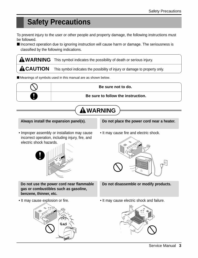
To prevent injury to the user or other people and property damage, the following instructions mustbe followed.■ Incorrect operation due to ignoring instruction will cause harm or damage. The seriousness is
classified by the following indications.
■ Meanings of symbols used in this manual are as shown below.
WARNING
CAUTION
This symbol indicates the possibility of death or serious injury.
This symbol indicates the possibility of injury or damage to property only.
Be sure not to do.
Be sure to follow the instruction.
WARNING
Always install the expansion panel(s).
• Improper assembly or installation may causeincorrect operation, including injury, fire, andelectric shock hazards.
Do not place the power cord near a heater.
• It may cause fire and electric shock.
Do not use the power cord near flammablegas or combustibles such as gasoline,benzene, thinner, etc.
• It may cause explosion or fire.
Do not disassemble or modify products.
• It may cause electric shock and failure.
Gasolin
4 Room Air Conditioner
Safety Precautions
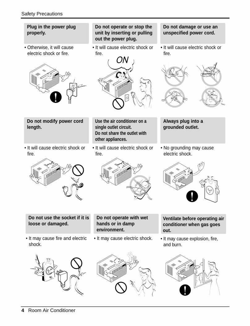
Plug in the power plugproperly.
• Otherwise, it will causeelectric shock or fire.
Do not operate or stop theunit by inserting or pullingout the power plug.
• It will cause electric shock orfire.
Do not damage or use anunspecified power cord.
• It will cause electric shock orfire.
Do not modify power cordlength.
• It will cause electric shock orfire.
Use the air conditioner on asingle outlet circuit. Do not share the outlet withother appliances.
• It will cause electric shock orfire.
Always plug into agrounded outlet.
• No grounding may causeelectric shock.
Do not use the socket if it isloose or damaged.
• It may cause fire and electricshock.
Do not operate with wethands or in dampenvironment.
• It may cause electric shock.
ON
ON
Ventilate before operating airconditioner when gas goesout.
• It may cause explosion, fire,and burn.
Service Manual 5
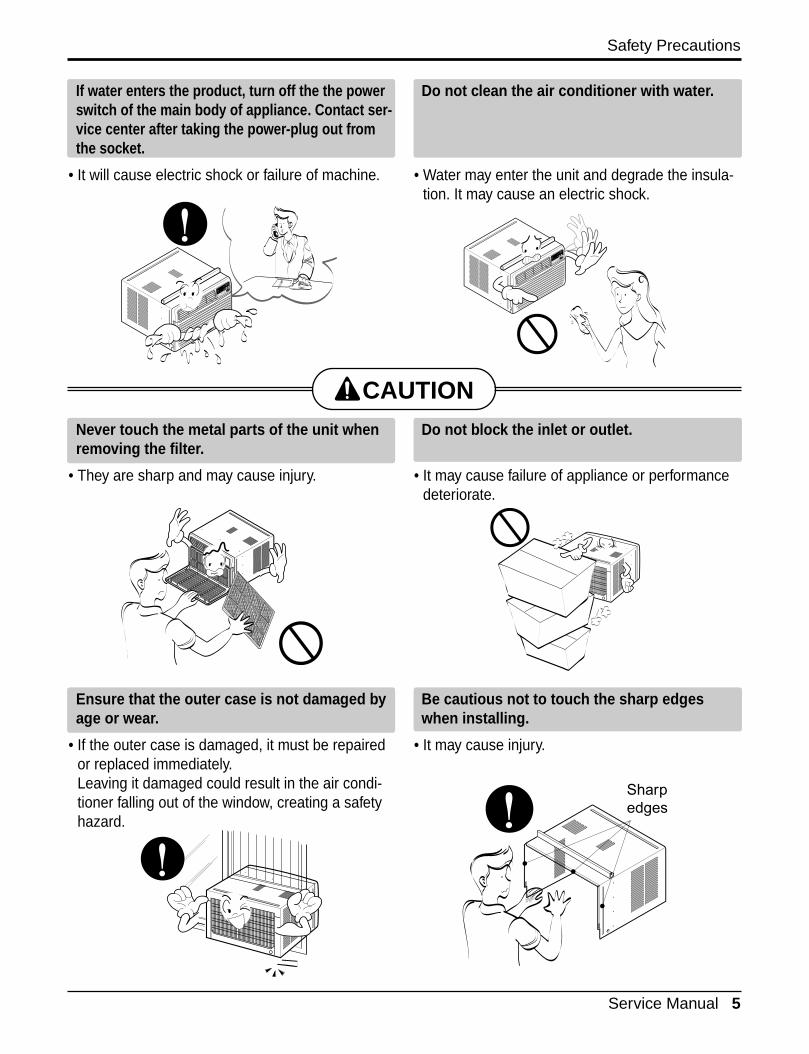
If water enters the product, turn off the the powerswitch of the main body of appliance. Contact ser-vice center after taking the power-plug out fromthe socket.
• It will cause electric shock or failure of machine.
Do not clean the air conditioner with water.
• Water may enter the unit and degrade the insula-tion. It may cause an electric shock.
Never touch the metal parts of the unit whenremoving the filter.
• They are sharp and may cause injury.
Do not block the inlet or outlet.
• It may cause failure of appliance or performancedeteriorate.
Ensure that the outer case is not damaged byage or wear.
• If the outer case is damaged, it must be repairedor replaced immediately. Leaving it damaged could result in the air condi-tioner falling out of the window, creating a safetyhazard.
Be cautious not to touch the sharp edgeswhen installing.
• It may cause injury.
CAUTION
Safety Precautions
Sharp edges
6 Room Air Conditioner
Dimensions
Dimensions
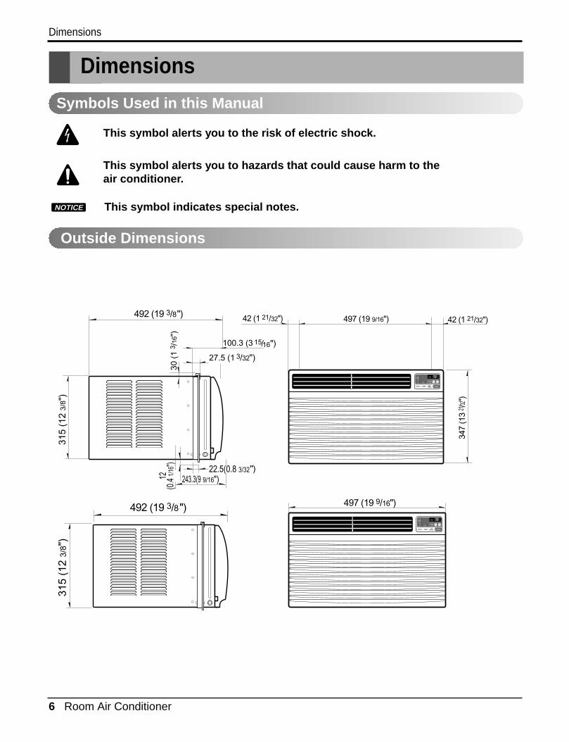
Outside Dimensions
This symbol alerts you to the risk of electric shock.
This symbol alerts you to hazards that could cause harm to theair conditioner.
This symbol indicates special notes.NOTICE
Symbols Used in this Manual
497 (19 9/16")
492 (19 3/8")
315
(12
3/8"
)
30 (
1 3 /
16")
243.3(9 9/16")12(0
.4 1/1
6") 22.5(0.8 3/32")
100.3 (3
27.5 (1 3/32")
")/1516
'F
TIMER POWERMODE
TEMP
FANSPEED
F1 LOWF2 MEDF3 HIGH
Dry Timer
Fan
EnergySaver
Cool
'F
TIMER POWERMODE
TEMP
FANSPEED
F1 LOWF2 MEDF3 HIGH
Dry Timer
Fan
EnergySaver
Cool
347
(13
21 /32"
)
497 (19 9/16") 42 (1 21/32")42 (1 21/32")
492 (19 3/8")
315
(12
3/8"
)
Specfications
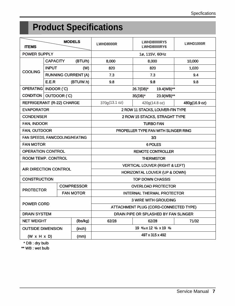
Product Specifications
POWER SUPPLY
CAPACITY
POWER SUPPLYPOWER SUPPLY
(BTU/h)CAPACITYCAPACITY
INPUT
(BTU/h)(BTU/h)
POWER SUPPLY
(W)INPUTINPUT
CAPACITY
COOLING(W)(W)
(BTU/h)
RUNNING CURRENTCOOLINGCOOLING
INPUT
(A)RUNNING CURRENTRUNNING CURRENT
(W)
E.E.R
(A)(A)COOLING
(BTU/W.h)E.E.RE.E.R
RUNNING CURRENT
INDOOR (
(BTU/W.h)(BTU/W.h)
(A)
C)INDOOR (INDOOR (
E.E.R
OUTDOOR (
C)C)
(BTU/W.h)
C)OUTDOOR (OUTDOOR (
INDOOR (
REFRIGERANT (R-22) CHARGE
C)C)
C)
EVAPORATOR
REFRIGERANT (R-22) CHARGEREFRIGERANT (R-22) CHARGE
OUTDOOR (
CONDENSER
EVAPORATOREVAPORATOR
C)
FAN, INDOOR
CONDENSERCONDENSER
REFRIGERANT (R-22) CHARGE
FAN, OUTDOOR
FAN, INDOORFAN, INDOOR
EVAPORATOR
FAN SPEEDS, FAN/COOLING/HEATING
FAN, OUTDOORFAN, OUTDOOR
CONDENSER
FAN MOTOR
FAN SPEEDS, FAN/COOLING/HEATINGFAN SPEEDS, FAN/COOLING/HEATING
FAN, INDOOR
OPERATION CONTROL
FAN MOTORFAN MOTOR
FAN, OUTDOOR
ROOM TEMP. CONTROL
OPERATION CONTROLOPERATION CONTROL
FAN SPEEDS, FAN/COOLING/HEATING
AIR DIRECTION CONTROL
ROOM TEMP. CONTROLROOM TEMP. CONTROL
FAN MOTOR
CONSTRUCTION
AIR DIRECTION CONTROLAIR DIRECTION CONTROL
OPERATION CONTROL
PROTECTOR
CONSTRUCTIONCONSTRUCTION
ROOM TEMP. CONTROL
COMPRESSORPROTECTORPROTECTOR
AIR DIRECTION CONTROL
FAN MOTOR
COMPRESSORCOMPRESSOR
CONSTRUCTION
POWER CORD
FAN MOTORFAN MOTORPROTECTOR
DRAIN SYSTEM
POWER CORDPOWER CORD
COMPRESSOR
NET WEIGHT
DRAIN SYSTEMDRAIN SYSTEM
FAN MOTOR
(lbs/kg)NET WEIGHTNET WEIGHT
POWER CORD
OUTSIDE DIMENSION (inch)
(lbs/kg)(lbs/kg)
DRAIN SYSTEM
(W x
OUTSIDE DIMENSION (inch)OUTSIDE DIMENSION (inch)
NET WEIGHT
H(W x(W x
(lbs/kg)
xHH
OUTSIDE DIMENSION (inch)
D) x x(W x (mm)D) D) H (mm)(mm) x
1ø, 115V, 60Hz
D)
8,000
1ø, 115V, 60Hz1ø, 115V, 60Hz
(mm)
8,0008,0008,000 10,0008,0008,000
1ø, 115V, 60Hz
820
10,00010,0008,000
820820
8,000
1,020
10,000
7.3
1,0201,020820
7.37.3 9.4
1,020
9.8
9.49.47.3
9.89.8 9.8
9.4
26.7(DB)* 19.4(WB)**
9.89.89.8
35(DB)* 23.9(WB)**
26.7(DB)* 19.4(WB)**26.7(DB)* 19.4(WB)**
35(DB)* 23.9(WB)**35(DB)* 23.9(WB)**
9.8
(13.1 oz)
26.7(DB)* 19.4(WB)**
480g(16.9 oz)420g(14.8 oz)
35(DB)* 23.9(WB)**
2 ROW 11 STACKS, LOUVER-FIN TYPE
480g(16.9 oz)480g(16.9 oz)370g
2 ROW 15 STACKS, STRAGHT TYPE
2 ROW 11 STACKS, LOUVER-FIN TYPE2 ROW 11 STACKS, LOUVER-FIN TYPE
TURBO FAN
2 ROW 15 STACKS, STRAGHT TYPE2 ROW 15 STACKS, STRAGHT TYPE
480g(16.9 oz)
PROPELLER TYPE FAN WITH SLINGER RING
TURBO FANTURBO FAN
2 ROW 11 STACKS, LOUVER-FIN TYPE
3/3
PROPELLER TYPE FAN WITH SLINGER RINGPROPELLER TYPE FAN WITH SLINGER RING
2 ROW 15 STACKS, STRAGHT TYPE
6 POLES
3/33/3
TURBO FAN
REMOTE CONTROLLER
6 POLES6 POLES
PROPELLER TYPE FAN WITH SLINGER RING
THERMISTOR
REMOTE CONTROLLERREMOTE CONTROLLER
3/3
VERTICAL LOUVER (RIGHT & LEFT)
THERMISTORTHERMISTOR
6 POLES
HORIZONTAL LOUVER (UP & DOWN)
VERTICAL LOUVER (RIGHT & LEFT)VERTICAL LOUVER (RIGHT & LEFT)
REMOTE CONTROLLER
TOP DOWN CHASSIS
HORIZONTAL LOUVER (UP & DOWN)HORIZONTAL LOUVER (UP & DOWN)
THERMISTOR
OVERLOAD PROTECTOR
TOP DOWN CHASSISTOP DOWN CHASSIS
VERTICAL LOUVER (RIGHT & LEFT)
INTERNAL THERMAL PROTECTOR
OVERLOAD PROTECTOROVERLOAD PROTECTOR
HORIZONTAL LOUVER (UP & DOWN)
3 WIRE WITH GROUDING
INTERNAL THERMAL PROTECTORINTERNAL THERMAL PROTECTOR
TOP DOWN CHASSIS
ATTACHMENT PLUG (CORD-CONNECTED TYPE)
3 WIRE WITH GROUDING3 WIRE WITH GROUDING
OVERLOAD PROTECTOR
DRAIN PIPE OR SPLASHED BY FAN SLINGER
ATTACHMENT PLUG (CORD-CONNECTED TYPE)ATTACHMENT PLUG (CORD-CONNECTED TYPE)
INTERNAL THERMAL PROTECTOR
62/28
DRAIN PIPE OR SPLASHED BY FAN SLINGERDRAIN PIPE OR SPLASHED BY FAN SLINGER
3 WIRE WITH GROUDING
71/3262/2862/28
ATTACHMENT PLUG (CORD-CONNECTED TYPE)
62/28 71/3271/32
DRAIN PIPE OR SPLASHED BY FAN SLINGER
19
62/2862/28 62/28
919 19
71/32
/99
62/28
16//19 x 1216169 3x 12x 12/ /3316 8//x 12 x 19883 3x 19x 19/ /338 8//x 19
497 x 315 x 492
883
LWHD8000R
497 x 315 x 492497 x 315 x 492
/8
497 x 315 x 492
LWHD8000RY5 LWHD1000RMODELSITEMS
MODELSMODELSITEMSITEMS
OPERATING
MODELS
CONDITION
OPERATINGOPERATING
ITEMS
* D
CONDITIONCONDITION
B* D* D
OPERATING
: dry bulbBB
CONDITION
** WB : wet bulb : dry bulb : dry bulb* D
** WB : wet bulb** WB : wet bulbB : dry bulb
** WB : wet bulb
Service Manual 7
820820820
7.3
820
7.37.3
9.89.8
7.3
9.89.89.89.89.89.8
LWHD8000RY6
8 Room Air Conditioner
Installation
Installation
Select the Best Location
Installation Check
How to Secure the Drain Pipe
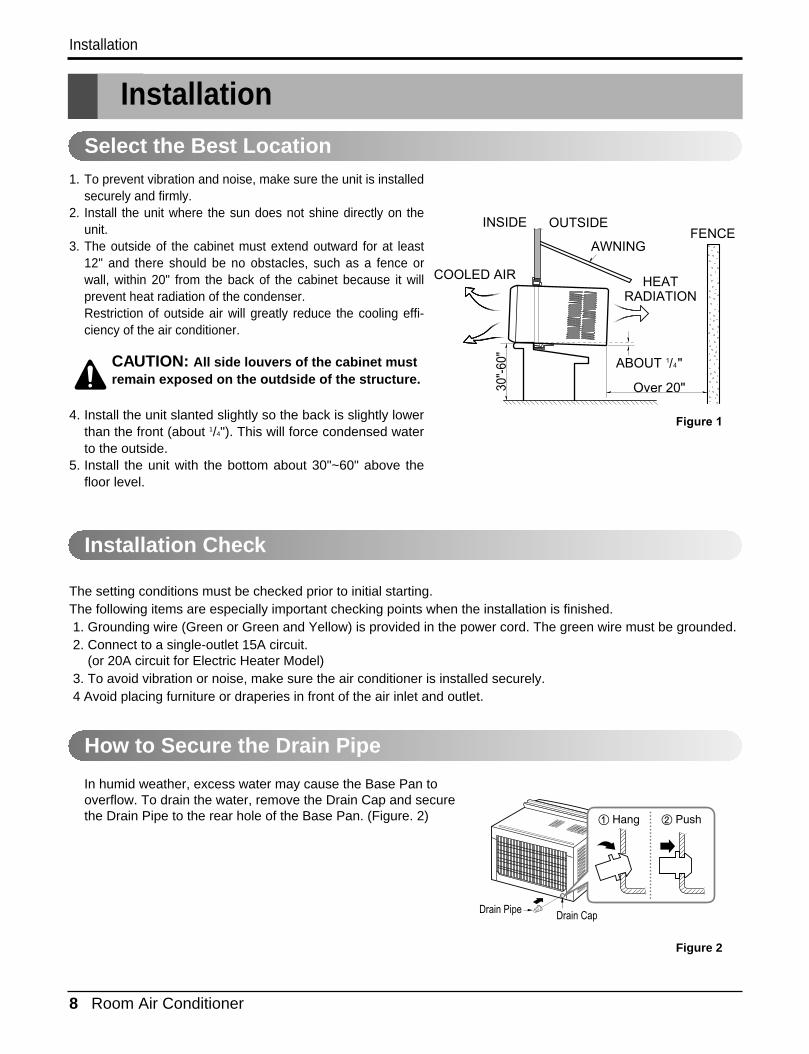
1. To prevent vibration and noise, make sure the unit is installedsecurely and firmly.
2. Install the unit where the sun does not shine directly on theunit.
3. The outside of the cabinet must extend outward for at least12" and there should be no obstacles, such as a fence orwall, within 20" from the back of the cabinet because it willprevent heat radiation of the condenser.Restriction of outside air will greatly reduce the cooling effi-ciency of the air conditioner.
CAUTION: All side louvers of the cabinet mustremain exposed on the outdside of the structure.
4. Install the unit slanted slightly so the back is slightly lowerthan the front (about 1/4"). This will force condensed waterto the outside.
5. Install the unit with the bottom about 30"~60" above thefloor level.
The setting conditions must be checked prior to initial starting.The following items are especially important checking points when the installation is finished.1. Grounding wire (Green or Green and Yellow) is provided in the power cord. The green wire must be grounded.2. Connect to a single-outlet 15A circuit.
(or 20A circuit for Electric Heater Model)3. To avoid vibration or noise, make sure the air conditioner is installed securely.4 Avoid placing furniture or draperies in front of the air inlet and outlet.
In humid weather, excess water may cause the Base Pan tooverflow. To drain the water, remove the Drain Cap and securethe Drain Pipe to the rear hole of the Base Pan. (Figure. 2)
Figure 2
ABOUT / "
Over 20"
HEATRADIATION
FENCEAWNING
OUTSIDE INSIDE
COOLED AIR
30"-
60"
14
Figure 1
Drain Pipe Drain Cap
Service Manual 9
Installation
How to Install
Window Requirements
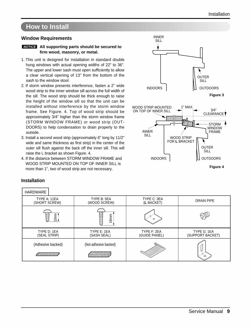
All supporting parts should be secured tofirm wood, masonry, or metal.
1. This unit is designed for installation in standard doublehung windows with actual opening widths of 22" to 36".The upper and lower sash must open sufficiently to allowa clear vertical opening of 13" from the bottom of thesash to the window stool.
2. If storm window presents interference, fasten a 2" widewood strip to the inner window sill across the full width ofthe sill. The wood strip should be thick enough to raisethe height of the window sill so that the unit can beinstalled without interference by the storm windowframe. See Figure. 4. Top of wood strip should beapproximately 3/4" higher than the storm window frame(STORM WINDOW FRAME) or wood strip (OUT-DOORS) to help condensation to drain properly to theoutside.
3. Install a second wood strip (approximately 6" long by 11/2"wide and same thickness as first strip) in the center of theouter sill flush against the back off the inner sill. This willraise the L bracket as shown Figure. 4.
4. If the distance between STORM WINDOW FRAME andWOOD STRIP MOUNTED ON TOP OF INNER SILL ismore than 1", two of wood strip are not necessary.
Installation
NOTICE
OUTDOORSINDOORS
INNERSILL
OUTERSILL
INNERSILL
WOOD STRIP MOUNTEDON TOP OF INNER SILL
WOOD STRIPFOR L BRACKET
3/4"CLEARANCE
1" MAX.
STORMWINDOWFRAME
OUTDOORSINDOORS
OUTERSILL
Figure 3
Figure 4
HARDWARE
TYPE E: 1EA(SASH SEAL)
(Not adhesive backed)
TYPE D: 1EA(SEAL STRIP)
(Adhesive backed)
TYPE F: 2EA(GUIDE PANEL)
TYPE C: 3EA(L BACKET)
TYPE A: 11EA(SHORT SCREW)
10m
m
TYPE B: 5EA(WOOD SCREW)
16m
m
TYPE G: 1EA(SUPPORT BACKET)
DRAIN PIPE
10 Room Air Conditioner
Installation
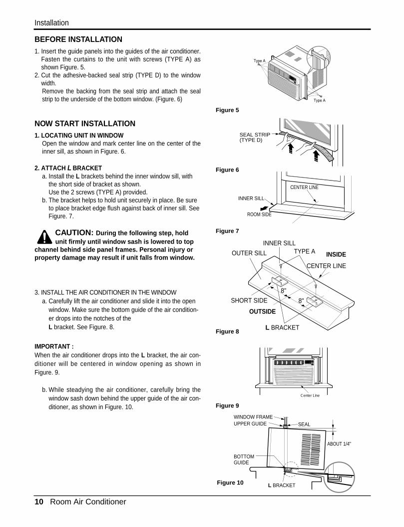
BEFORE INSTALLATION1. Insert the guide panels into the guides of the air conditioner.
Fasten the curtains to the unit with screws (TYPE A) asshown Figure. 5.
2. Cut the adhesive-backed seal strip (TYPE D) to the windowwidth.Remove the backing from the seal strip and attach the sealstrip to the underside of the bottom window. (Figure. 6)
NOW START INSTALLATION1. LOCATING UNIT IN WINDOW
Open the window and mark center line on the center of theinner sill, as shown in Figure. 6.
2. ATTACH L BRACKETa. Install the L brackets behind the inner window sill, with
the short side of bracket as shown. Use the 2 screws (TYPE A) provided.
b. The bracket helps to hold unit securely in place. Be sureto place bracket edge flush against back of inner sill. SeeFigure. 7.
CAUTION: During the following step, holdunit firmly until window sash is lowered to top
channel behind side panel frames. Personal injury orproperty damage may result if unit falls from window.
3. INSTALL THE AIR CONDITIONER IN THE WINDOWa. Carefully lift the air conditioner and slide it into the open
window. Make sure the bottom guide of the air condition-er drops into the notches of the L bracket. See Figure. 8.
IMPORTANT :When the air conditioner drops into the L bracket, the air con-ditioner will be centered in window opening as shown inFigure. 9.
b. While steadying the air conditioner, carefully bring thewindow sash down behind the upper guide of the air con-ditioner, as shown in Figure. 10.
ROOM SIDE
CENTER LINE
INNER SILL
SEAL STRIP(TYPE D)
OUTSIDE
INSIDE
L BRACKET
OUTER SILL
SHORT SIDE
INNER SILLTYPE A
8"
8"
CENTER LINE
SEALWINDOW FRAME
BOTTOMGUIDE
ABOUT 1/4"
L BRACKET
UPPER GUIDE
Figure 5
Figure 6
Figure 7
Figure 8
Figure 9
Figure 10
Type A
Type A
C enter Line
F
T E MP
F 1 L OWF 2 ME DF 3 HIG H
Dry T imer
Fan
E nergyS aver
C ool
Service Manual 11
Installation
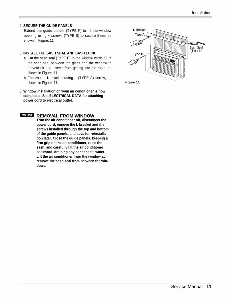
4. SECURE THE GUIDE PANELSExtend the guide panels (TYPE F) to fill the windowopening using 4 screws (TYPE B) to secure them, asshown in Figure. 11.
5. INSTALL THE SASH SEAL AND SASH LOCKa. Cut the sash seal (TYPE E) to the window width. Stuff
the sash seal between the glass and the window toprevent air and insects from getting into the room, asshown in Figure. 11.
b. Fasten the L bracket using a (TYPE A) screw, asshown in Figure. 11.
6. Window installation of room air conditioner is nowcompleted. See ELECTRICAL DATA for attachingpower cord to electrical outlet.
REMOVAL FROM WINDOWTrun the air conditioner off, disconnect thepower cord, remove the L bracket and thescrews installed through the top and bottomof the guide panels, and save for reinstalla-tion later. Close the guide panels. keeping afirm grip on the air conditioner, raise thesash, and carefully tilt the air conditionerbackward, draining any condensate water.Lift the air conditioner from the window adremove the sash seal from between the win-dows.
NOTICE
Figure 11
Type B
Sash Seal(Type F)
L Bracket
Type A
12 Room Air Conditioner
Operation
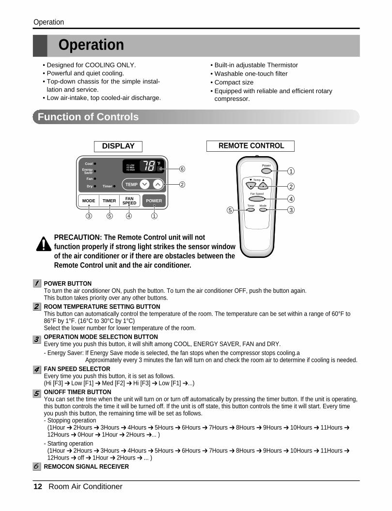
Operation• Designed for COOLING ONLY.• Powerful and quiet cooling.• Top-down chassis for the simple instal-
lation and service.• Low air-intake, top cooled-air discharge.
• Built-in adjustable Thermistor• Washable one-touch filter• Compact size• Equipped with reliable and efficient rotary
compressor.
REMOTE CONTROLDISPLAY
'F
TIMER POWERMODE
TEMP
FANSPEED
F1 LOWF2 MEDF3 HIGH
Dry Timer
Fan
EnergySaver
Cool Power
Temp
Fan Speed
Timer Mode
1
2
3
4
51
2
6
3 45
PRECAUTION: The Remote Control unit will not function properly if strong light strikes the sensor windowof the air conditioner or if there are obstacles between theRemote Control unit and the air conditioner.
POWER BUTTONTo turn the air conditioner ON, push the button. To turn the air conditioner OFF, push the button again.This button takes priority over any other buttons.ROOM TEMPERATURE SETTING BUTTONThis button can automatically control the temperature of the room. The temperature can be set within a range of 60°F to86°F by 1°F. (16°C to 30°C by 1°C)Select the lower number for lower temperature of the room.OPERATION MODE SELECTION BUTTONEvery time you push this button, it will shift among COOL, ENERGY SAVER, FAN and DRY.- Energy Saver: If Energy Save mode is selected, the fan stops when the compressor stops cooling.a
Approximately every 3 minutes the fan will turn on and check the room air to determine if cooling is needed.FAN SPEED SELECTOREvery time you push this button, it is set as follows. (Hi [F3] ➔ Low [F1] ➔ Med [F2] ➔ Hi [F3] ➔ Low [F1] ➔ ...)ON/OFF TIMER BUTTONYou can set the time when the unit will turn on or turn off automatically by pressing the timer button. If the unit is operating,this button controls the time it will be turned off. If the unit is off state, this button controls the time it will start. Every timeyou push this button, the remaining time will be set as follows.- Stopping operation
(1Hour ➔ 2Hours ➔ 3Hours ➔ 4Hours ➔ 5Hours ➔ 6Hours ➔ 7Hours ➔ 8Hours ➔ 9Hours ➔ 10Hours ➔ 11Hours ➔12Hours ➔ 0Hour ➔ 1Hour ➔ 2Hours ➔... )
- Starting operation(1Hour ➔ 2Hours ➔ 3Hours ➔ 4Hours ➔ 5Hours ➔ 6Hours ➔ 7Hours ➔ 8Hours ➔ 9Hours ➔ 10Hours ➔ 11Hours ➔12Hours ➔ off ➔ 1Hour ➔ 2Hours ➔ ... )
REMOCON SIGNAL RECEIVER
Function of Controls
Service Manual 13
Disassembly
Disassembly
Mechanical Parts
— Before the following disassembly, set the CONTROL BOX to OFF and disconnect the power cord.
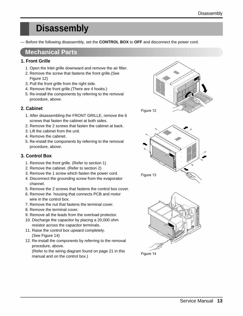
1. Front Grille1. Open the lnlet grille downward and remove the air filter.2. Remove the screw that fastens the front grille.(See
Figure 12)3. Pull the front grille from the right side.4. Remove the front grille.(There are 4 hooks.)5. Re-install the components by referring to the removal
procedure, above.
2. Cabinet1. After disassembling the FRONT GRILLE, remove the 6
screws that fasten the cabinet at both sides.2. Remove the 2 screws that fasten the cabinet at back.3. Lift the cabinet from the unit. 4. Remove the cabinet.5. Re-install the components by referring to the removal
procedure, above.
3. Control Box1. Remove the front grille. (Refer to section 1)2. Remove the cabinet. (Refer to section 2)3. Remove the 1 screw which fasten the power cord.4. Disconnect the grounding screw from the evaporator
channel.5. Remove the 2 screws that fastens the control box cover.6. Remove the housing that connects PCB and motor
wire in the control box.7. Remove the nut that fastens the terminal cover.8. Remove the terminal cover.9. Remove all the leads from the overload protector.10. Discharge the capacitor by placing a 20,000 ohm
resistor across the capacitor terminals.11. Raise the control box upward completely.
(See Figure 14)12. Re-install the components by referring to the removal
procedure, above. (Refer to the wiring diagram found on page 21 in thismanual and on the control box.)
Figure 12
Figure 13
Figure 14
14 Room Air Conditioner
Disassembly
Figure 15
Figure 16
Figure 17
Figure 18
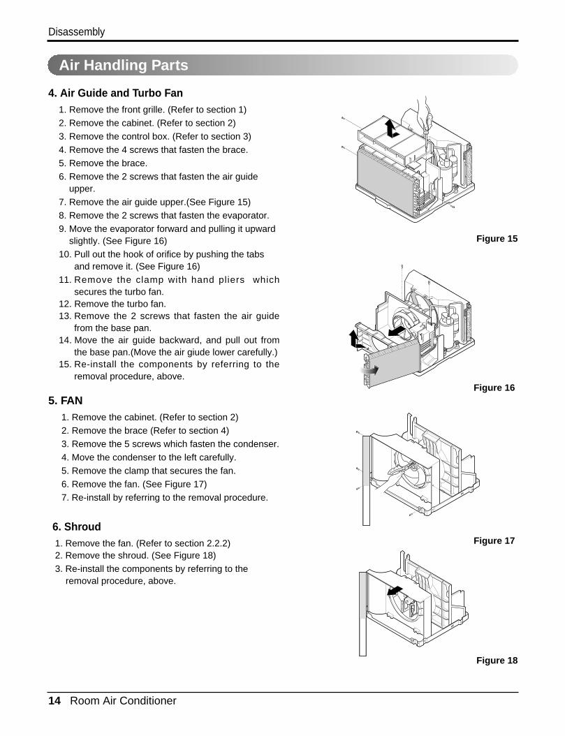
4. Air Guide and Turbo Fan1. Remove the front grille. (Refer to section 1)2. Remove the cabinet. (Refer to section 2)3. Remove the control box. (Refer to section 3)4. Remove the 4 screws that fasten the brace.5. Remove the brace.6. Remove the 2 screws that fasten the air guide
upper.7. Remove the air guide upper.(See Figure 15)8. Remove the 2 screws that fasten the evaporator.9. Move the evaporator forward and pulling it upward
slightly. (See Figure 16)10. Pull out the hook of orifice by pushing the tabs
and remove it. (See Figure 16)11. Remove the clamp with hand pliers which
secures the turbo fan.12. Remove the turbo fan.13. Remove the 2 screws that fasten the air guide
from the base pan.14. Move the air guide backward, and pull out from
the base pan.(Move the air giude lower carefully.)15. Re-install the components by referring to the
removal procedure, above.
5. FAN1. Remove the cabinet. (Refer to section 2)2. Remove the brace (Refer to section 4)3. Remove the 5 screws which fasten the condenser.4. Move the condenser to the left carefully.5. Remove the clamp that secures the fan.6. Remove the fan. (See Figure 17)7. Re-install by referring to the removal procedure.
Air Handling Parts
6. Shroud1. Remove the fan. (Refer to section 2.2.2)2. Remove the shroud. (See Figure 18)3. Re-install the components by referring to the
removal procedure, above.
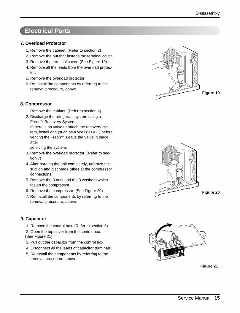
7. Overload Protector1. Remove the cabinet. (Refer to section 2)2. Remove the nut that fastens the terminal cover.3. Remove the terminal cover. (See Figure 19)4. Remove all the leads from the overload protec-
tor.5. Remove the overload protector.6. Re-install the components by referring to the
removal procedure, above.
8. Compressor1. Remove the cabinet. (Refer to section 2)2. Discharge the refrigerant system using a
FreonTM Recovery System.If there is no valve to attach the recovery sys-tem, install one (such as a WATCO A-1) beforeventing the FreonTM. Leave the valve in placeafter servicing the system.
3. Remove the overload protector. (Refer to sec-tion 7)
4. After purging the unit completely, unbraze thesuction and discharge tubes at the compressorconnections.
5. Remove the 3 nuts and the 3 washers which fasten the compressor.
6. Remove the compressor. (See Figure 20)7. Re-install the components by referring to the
removal procedure, above.
Service Manual 15
Disassembly
Electrical Parts
Figure 19
Figure 20
9. Capacitor1. Remove the control box. (Refer to section 3)
2. Open the top cover from the control box.(See Figure 21)
3. Pull out the capacitor from the control box.
4. Disconnect all the leads of capacitor terminals.
5. Re-install the components by referring to theremoval procedure, above.
Figure 21
16 Room Air Conditioner
Disassembly
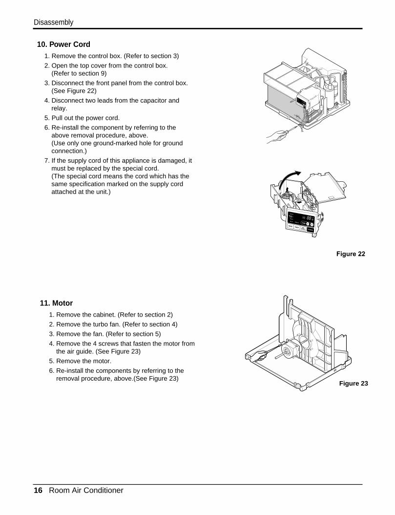
10. Power Cord1. Remove the control box. (Refer to section 3)
2. Open the top cover from the control box.(Refer to section 9)
3. Disconnect the front panel from the control box.(See Figure 22)
4. Disconnect two leads from the capacitor andrelay.
5. Pull out the power cord.
6. Re-install the component by referring to theabove removal procedure, above.(Use only one ground-marked hole for groundconnection.)
7. If the supply cord of this appliance is damaged, itmust be replaced by the special cord. (The special cord means the cord which has thesame specification marked on the supply cordattached at the unit.)
11. Motor1. Remove the cabinet. (Refer to section 2)
2. Remove the turbo fan. (Refer to section 4)
3. Remove the fan. (Refer to section 5)
4. Remove the 4 screws that fasten the motor fromthe air guide. (See Figure 23)
5. Remove the motor.
6. Re-install the components by referring to theremoval procedure, above.(See Figure 23)
Figure 23
Figure 22
Service Manual 17
Disassembly
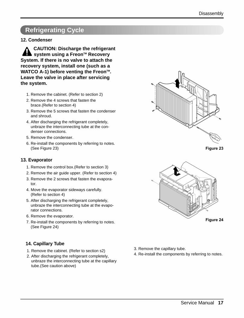
12. Condenser
CAUTION: Discharge the refrigerantsystem using a FreonTM Recovery
System. If there is no valve to attach therecovery system, install one (such as aWATCO A-1) before venting the FreonTM.Leave the valve in place after servicingthe system.
1. Remove the cabinet. (Refer to section 2)
2. Remove the 4 screws that fasten thebrace.(Refer to section 4)
3. Remove the 5 screws that fasten the condenserand shroud.
4. After discharging the refrigerant completely,unbraze the interconnecting tube at the con-denser connections.
5. Remove the condenser.
6. Re-install the components by referring to notes.(See Figure 23)
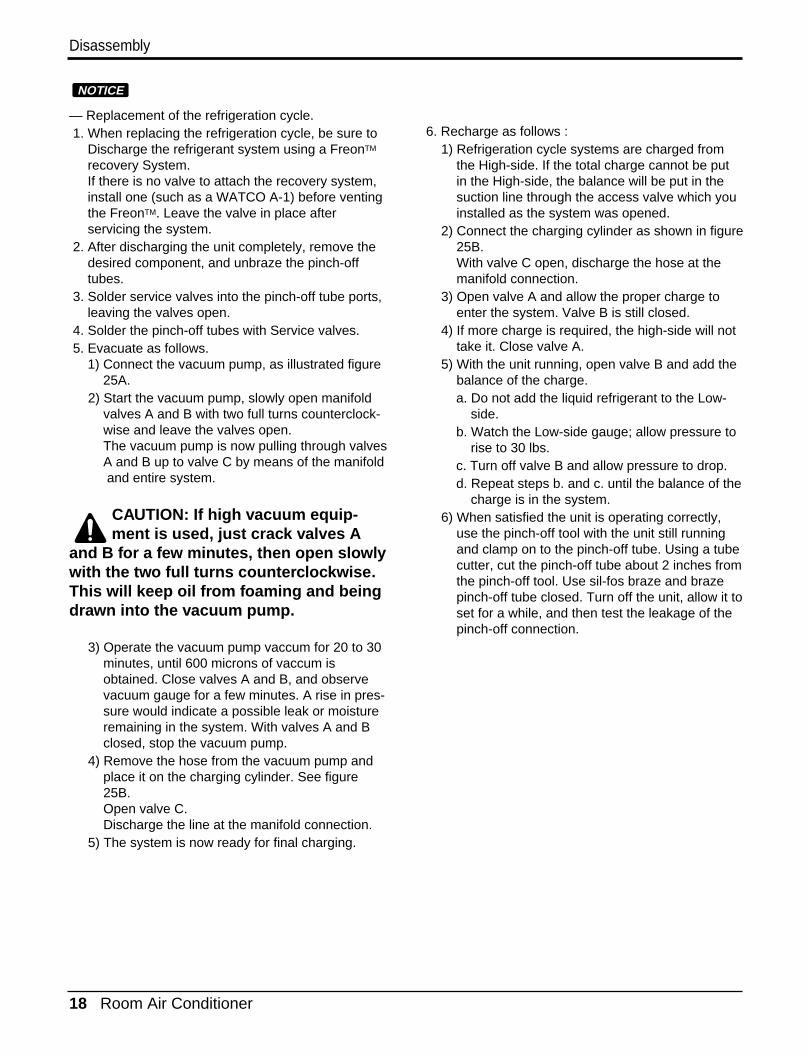
13. Evaporator1. Remove the control box.(Refer to section 3)
2. Remove the air guide upper. (Refer to section 4)
3. Remove the 2 screws that fasten the evapora-tor.
4. Move the evaporator sideways carefully.(Refer to section 4)
5. After discharging the refrigerant completely,unbraze the interconnecting tube at the evapo-rator connections.
6. Remove the evaporator.
7. Re-install the components by referring to notes.(See Figure 24)
Refrigerating Cycle
14. Capillary Tube1. Remove the cabinet. (Refer to section s2)2. After discharging the refrigerant completely,
unbraze the interconnecting tube at the capillarytube.(See caution above)
3. Remove the capillary tube.4. Re-install the components by referring to notes.
Figure 23
Figure 24
18 Room Air Conditioner
Disassembly
— Replacement of the refrigeration cycle.1. When replacing the refrigeration cycle, be sure to
Discharge the refrigerant system using a FreonTM
recovery System.If there is no valve to attach the recovery system,install one (such as a WATCO A-1) before ventingthe FreonTM. Leave the valve in place after servicing the system.
2. After discharging the unit completely, remove thedesired component, and unbraze the pinch-offtubes.
3. Solder service valves into the pinch-off tube ports,leaving the valves open.
4. Solder the pinch-off tubes with Service valves.5. Evacuate as follows.
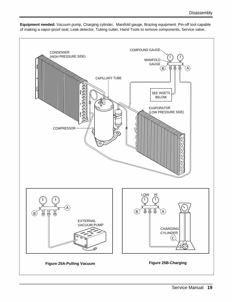
1) Connect the vacuum pump, as illustrated figure25A.
2) Start the vacuum pump, slowly open manifold valves A and B with two full turns counterclock-wise and leave the valves open.The vacuum pump is now pulling through valvesA and B up to valve C by means of the manifoldand entire system.
CAUTION: If high vacuum equip-ment is used, just crack valves A
and B for a few minutes, then open slowlywith the two full turns counterclockwise.This will keep oil from foaming and beingdrawn into the vacuum pump.
3) Operate the vacuum pump vaccum for 20 to 30minutes, until 600 microns of vaccum isobtained. Close valves A and B, and observevacuum gauge for a few minutes. A rise in pres-sure would indicate a possible leak or moistureremaining in the system. With valves A and Bclosed, stop the vacuum pump.
4) Remove the hose from the vacuum pump andplace it on the charging cylinder. See figure25B.Open valve C.Discharge the line at the manifold connection.
5) The system is now ready for final charging.
6. Recharge as follows :1) Refrigeration cycle systems are charged from
the High-side. If the total charge cannot be put in the High-side, the balance will be put in the suction line through the access valve which you installed as the system was opened.
2) Connect the charging cylinder as shown in figure 25B.With valve C open, discharge the hose at themanifold connection.
3) Open valve A and allow the proper charge to enter the system. Valve B is still closed.
4) If more charge is required, the high-side will not take it. Close valve A.
5) With the unit running, open valve B and add the balance of the charge.a. Do not add the liquid refrigerant to the Low-
side.b. Watch the Low-side gauge; allow pressure to
rise to 30 lbs.c. Turn off valve B and allow pressure to drop.d. Repeat steps b. and c. until the balance of the
charge is in the system.6) When satisfied the unit is operating correctly,
use the pinch-off tool with the unit still running and clamp on to the pinch-off tube. Using a tube cutter, cut the pinch-off tube about 2 inches from the pinch-off tool. Use sil-fos braze and braze pinch-off tube closed. Turn off the unit, allow it to set for a while, and then test the leakage of the pinch-off connection.
NOTICE
Service Manual 19
Disassembly
Equipment needed: Vacuum pump, Charging cylinder, Manifold gauge, Brazing equipment. Pin-off tool capableof making a vapor-proof seal, Leak detector, Tubing cutter, Hand Tools to remove components, Service valve.
A
COMPOUND GAUGE
EVAPORATOR(LOW PRESSURE SIDE)
COMPRESSOR
CAPILLARY TUBE
CONDENSER(HIGH PRESSURE SIDE)
SEE INSETSBELOW
MANIFOLDGAUGE
B
Figure 25A-Pulling Vacuum Figure 25B-Charging
A
B
EXTERNALVACUUM PUMP
A
CHARGINGCYLINDER
LOW HI
B
C
20 Room Air Conditioner
Schematic Diagram
33
22
11
HV
B
5V
b c
R04
P X O
O X
5VR
04P
8
EE
PR
OM
Mod
el
1
EE
PR
OM
A0
5V S71
36IC
01A
3.6V 21
R01
A20
K
3
+
10V
1uF
C02
AC
AT
93C
46 Vcc
Aut
o R
esta
rt
Non
Aut
o R
esta
rt
20K
R03
P20
K
57 6
R02
P
Q03
G
1KR04
P
A10
1SQ
01G
A10
1SQ
02G
SW
03G
D03
G
SW
06G
D06
G
TE
MP
UP
D02
G
D05
G
SW
02G
MO
DE
SW
05G
TE
MP
DO
WN
ON
/OF
F
D01
G
D04
G
FA
N
SW
01G
TIM
ER
SW
04G
A10
1S
42 3A
2
GN
D
A1
10K
R06
P
R05
P10
KR
x
SD
A
SC
L
Dig
it4 (
Sca
n4)
0.00
1C
01F
R01
F10
K
C02
F0.
001
R03
F10
K
Dig
it1 (
Sca
n1)
SE
G-c
SE
G-a
SE
G-b
Dig
it0 (
Sca
n0)
Dig
it2 (
Sca
n2)
Dig
it3 (
Sca
n3)
SC
L
SD
A
WP
0.01
C01
A
50V
1MR01
B
OS
C01
BR
T8.
00M
G
1%12.1
KR
02H
6.2K
1%R04
H
5V
2 1 CN
-TH
1S
MA
W20
0-02
2
11
2
5V
12
TEST
1413
891011
1619
18
VSS
VAref
1715Osc in
Osc out
/Reset
2120
22
24 25 2623
5V
4WA
Y
SY
NC
LOW
CO
MP
Pipe TH
Option1
Option2
Room TH
567 1234
MIC
OM
TM
P87
CH
47U
SEG-d44
SEG-e
SEG-f
4342
VDD40
SEG-g
3837
KEY0
39 SLIDE SW
41
27 28 29 31 32 3330
ION
ME
D HI
Rec
eive
r
LED
out
3
Buz
zer
3635
34
LED out0
LED out1
LED out2
KEY1
HV
B
R22
H
1%12.1
KR
21H
12.1
K 1%
OR
2H
7 456
9 8 7
OR
1H
131211105V
12
98
IC01
M
1K
R02
E20
GN
D
Vou
t
RE
CE
IVE
R
Vcc
R01
L
5 4
12V
+
5V
10V
220
C02
L
ULN
2004
A
1615143
6
680p
FC
01L
R01
P20
K 50V
3
Dig
it0
510
a
f
a
b
Dig
it1a
3 9b
8c d
f
d
e
d
c
7e
4f
1g
e
6g
g
CO
OL
DE
FR
OS
T
DR
Y/H
EA
T
TIM
ER
FA
N
E/S
AV
ER
R02
G
R03
G
R04
G
R01
G68
0
680
680
680
R05
G
R06
G
R07
G
12V
680
680
680
IC01
G
15 14 13432
161
12 11 10765
98
ULN
2004
A
10K
5V
5V
R12
FR
01E
1K
5V
C06
D
BZ
01E
PK
M13
EP
Y-4
002
+C
05D
50V
10V
220
0.01
10
12V
11 12 CN
-AC
/DC
5158
1-12
(YE
ON
HO
)52
044-
1245
(MO
LEX
)
C05
D5V12
V
I
C04
D
O78
05
IC02
D
25V
25V
0.01
0.01
AN
GLE
11 12R
x Tx
1KQ
03T
C10
4M
5V
5V Q02
TA
104M
Q01
TC
104M
Q04
TA
104M
C03
T0.
001
R01
T
25V
C02
T0.
001
D01
T1N
4148
C01
T0.
150
V
5V(R
D)
CN
-TE
LE
CN
-TH
2
SM
W20
0-03
SM
W25
0-02
4 65
J7
RY
-CO
MP
RY
-4W
AY
RY
-LO
W
98
CN
-TH
2
X O
X O
J07 O X
X O
RY
-4W
AY
RY
-ME
D
RY
-HI
CN
-4W
AY
7J5
22
PIP
E-T
H
22
11
33
11
22
SW
2
CN
-HV
BS
MW
200-
03(B
L)
CN
-CO
NT
SM
W20
0-03
(YL)
Mod
el
RY
-4W
AY
333
3 11
22
SW
1
33
11
CN
-4W
AY
YW
396-
03A
V(Y
L)
SM
W20
0-03
(WH
)C
N-1
2V
12V
Coo
l Onl
y
Hea
t Pum
p
11
10
S/V
-
4WA
Y
35V
2 1
12V C
N-A
C/D
C51
580-
1252
045-
1245
+
I78
12
IC01
D C03
DC
01D
D04
D+
O C02
D
16V
35V
50V
1000
1000
0.1
47
D02
D
D03
D21
PO
WE
R T
RA
NS
1N40
04D
02D
~D
05D
D05
D
ST
RA
IGH
T
RY
-HI
RY
-ME
D
RY
-LO
W R01
J
C01
J0.
1/27
5V
1 3
1 3
5 7 9
5 7 9 33
11
CN
-PW
R
CN
-MO
TO
RY
W39
6-09
AV
YW
396-
03A
V
SV
C27
1D-1
4AZ
NR
01J
SV
C27
1D-1
4A
RY
-CO
MP
G4A
-1A
-E-L
G
FU
SE
250V
T3.
15A
120
1/2W
CA
PA
CIT
OR C
MA
IN P
OW
ER
MO
TO
RF
AN
CO
MP
FA
N
HE
RM
RO
OM
-TH
88 S
EG
ME
NT
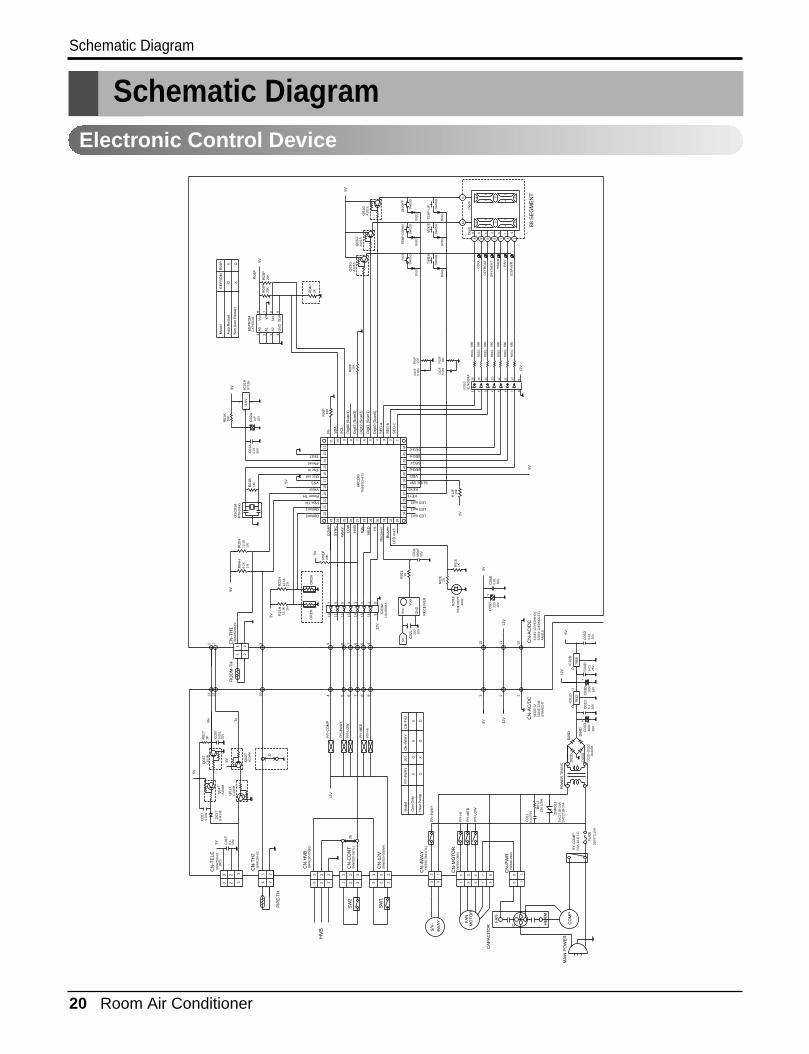
Electronic Control Device
Schematic Diagram
Service Manual 21
Schematic Diagram
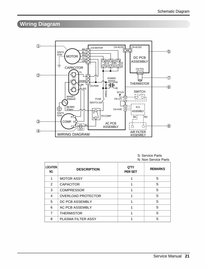
Wiring Diagram
MOTOR ASSY
CAPACITOR
COMPRESSOR
OVERLOAD PROTECTOR
DC PCB ASSEMBLY
AC PCB ASSEMBLY
THERMISTOR
PLASMA FILTER ASSY
1
2
3
4
5
6
7
8
1
1
1
1
1
1
1
1
S
S
S
S
S
S
S
S
LOCATIONNO.
DESCRIPTION REMARKSQ'TYPER SET
MOTOR
COMP.
CAPACITOR
DC PCBASSEMBLY
THERMISTOR
AIR FILTERASSEMBLY
AC PCBASSEMBLY
WIRING DIAGRAM
SWITCH
H.V.ASSEMBLY
BKCN-MOTOR
CN-PWR
DC12V
ZNR
01J
CN-12V
CN-HVB
RY-COMP3
4
FUSE
250V/T3.15A
RY-
LOW
RY-
ME
D
RY-
HI
CN-AC/DC
POWERTRANS
CN-AC/DC
CN-TH1
BLRD
RDBK
BL
R
S
COLP
YLOR
YLF
C
H
WH(BL)(Ribbed)
BK(BR)(Plain)
GN/YL(GN)
GN/YL(GN)
BK
RD
OR(BR)
1
5
7
6
8
4
2
3
S: Service PartsN: Non Service Parts
22 Room Air Conditioner
Schematic Diagram
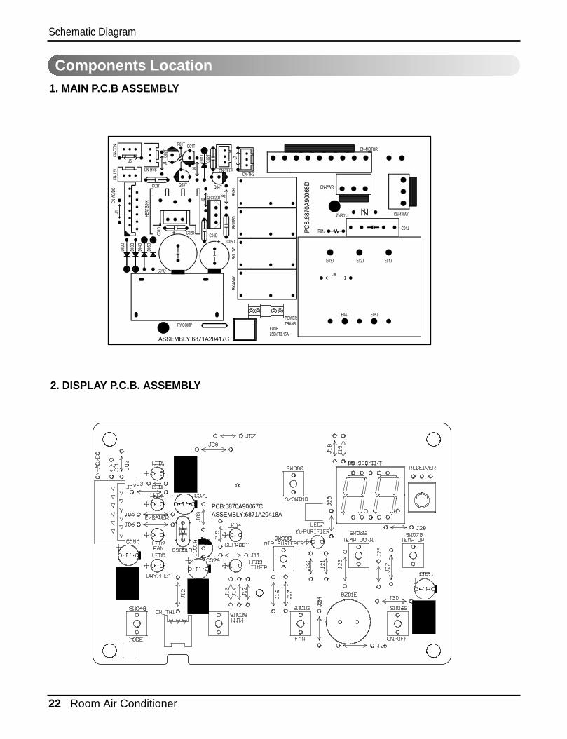
Components Location1. MAIN P.C.B ASSEMBLY
R01T
CN-HVB
C03T Q03T Q04T
C04DC05D
C01D
C02D
D02D
D03D
D04D
D05D
IC01
D
HEAT
SIN
K
QIC02DT
J5
Q01T
CN-TELECN-TH2
CN-PWR
CN-MOTOR
ZNR01J CN-4WAY
C01JR01J
E03J
E04JPOWERTRANS
FUSE250V/T3.15A
RY-COMP
E05J
E02J
J8
E01J
J6
J2
J3 RY-H
I
PC
B:6
870A
9006
8D
ASSEMBLY:6871A20417C
RY-M
EDRY
-LOW
RY-4
WAY
J7
J4
J1
D01T
C02TQ0
2T
CN-C
ONCN
-12V
CN-A
C/DC
2. DISPLAY P.C.B. ASSEMBLY
PCB:6870A90067C ASSEMBLY:6871A20418A
Service Manual 23
Troubleshooting Guide
Troubleshooting Guide
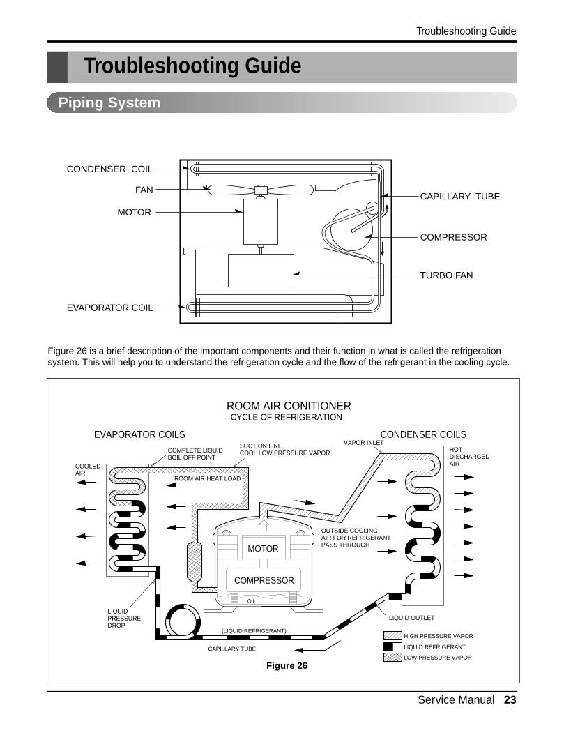
Piping System
Figure 26 is a brief description of the important components and their function in what is called the refrigerationsystem. This will help you to understand the refrigeration cycle and the flow of the refrigerant in the cooling cycle.
MOTOR
COMPRESSOR
OIL
(LIQUID REFRIGERANT)
CAPILLARY TUBE
OUTSIDE COOLINGAIR FOR REFRIGERANTPASS THROUGH
SUCTION LINECOOL LOW PRESSURE VAPOR
COOLEDAIR
COMPLETE LIQUIDBOIL OFF POINT
LIQUIDPRESSUREDROP
ROOM AIR HEAT LOAD
VAPOR INLETHOTDISCHARGEDAIR
LIQUID OUTLET
HIGH PRESSURE VAPOR
LIQUID REFRIGERANT
LOW PRESSURE VAPOR
ROOM AIR CONITIONER
EVAPORATOR COILS CONDENSER COILS
CYCLE OF REFRIGERATION
CAPILLARY TUBE
COMPRESSOR
TURBO FAN
CONDENSER COIL
EVAPORATOR COIL
FAN
MOTOR
Figure 26
24 Room Air Conditioner
Troubleshooting Guide
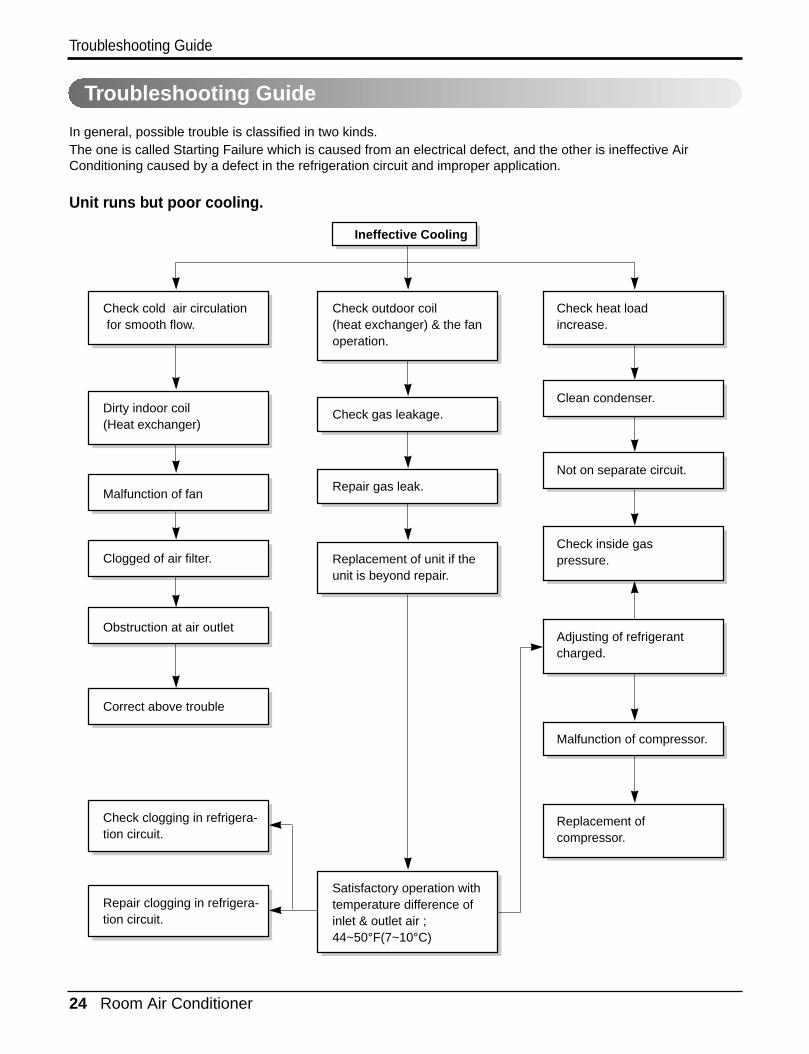
Troubleshooting Guide
In general, possible trouble is classified in two kinds.The one is called Starting Failure which is caused from an electrical defect, and the other is ineffective AirConditioning caused by a defect in the refrigeration circuit and improper application.
Unit runs but poor cooling.
Ineffective Cooling
Check outdoor coil(heat exchanger) & the fanoperation.
Check gas leakage.
Repair gas leak.
Replacement of unit if theunit is beyond repair.
Satisfactory operation withtemperature difference ofinlet & outlet air ; 44~50°F(7~10°C)
Check heat load increase.
Clean condenser.
Not on separate circuit.
Check inside gaspressure.
Adjusting of refrigerantcharged.
Malfunction of compressor.
Replacement ofcompressor.
Check cold air circulation for smooth flow.
Dirty indoor coil(Heat exchanger)
Correct above trouble
Check clogging in refrigera-tion circuit.
Repair clogging in refrigera-tion circuit.
Obstruction at air outlet
Clogged of air filter.
Malfunction of fan
Service Manual 25
Troubleshooting Guide
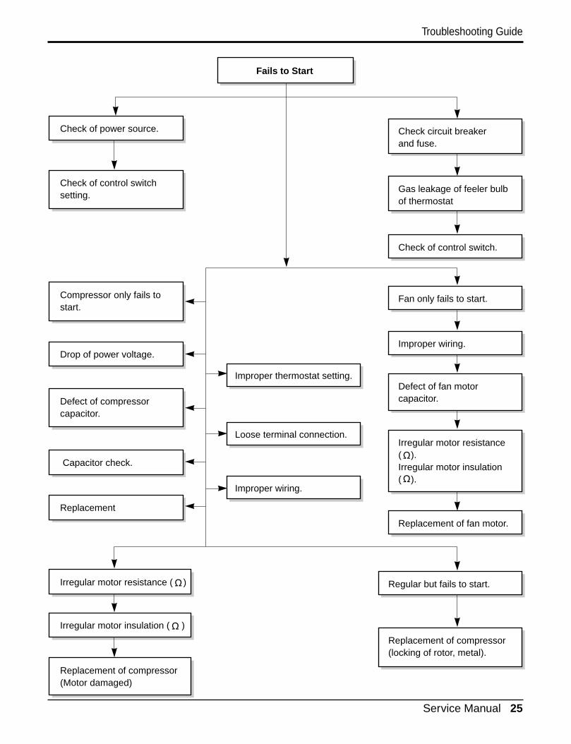
Fails to Start
Check circuit breakerand fuse.
Gas leakage of feeler bulbof thermostat
Check of control switch.
Fan only fails to start.
Improper wiring.
Defect of fan motorcapacitor.
Irregular motor resistance( ).Irregular motor insulation( ).
Replacement of fan motor.
Regular but fails to start.
Replacement of compressor(locking of rotor, metal).
Improper thermostat setting.
Loose terminal connection.
Improper wiring.
Irregular motor resistance ( )
Irregular motor insulation ( )
Replacement of compressor(Motor damaged)
Drop of power voltage.
Capacitor check.
Replacement
Compressor only fails tostart.
Defect of compressorcapacitor.
Check of power source.
Check of control switchsetting.
26 Room Air Conditioner
Troubleshooting Guide
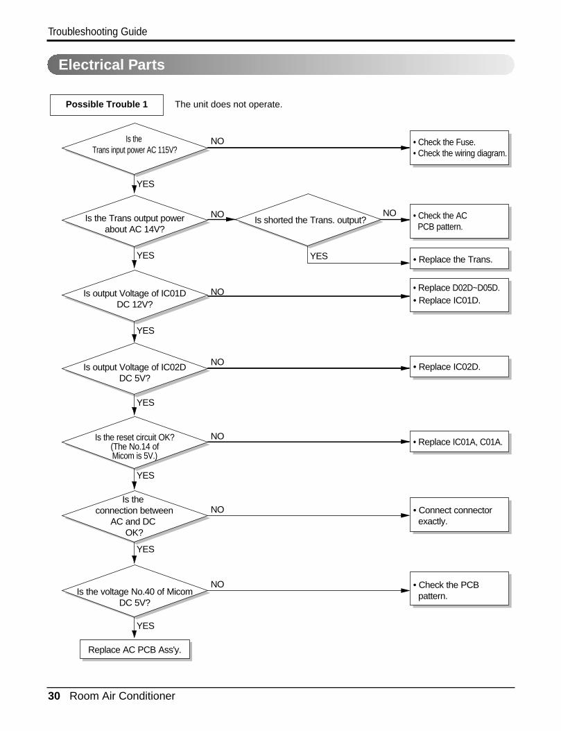
• Check the Fuse.• Check the wiring diagram.
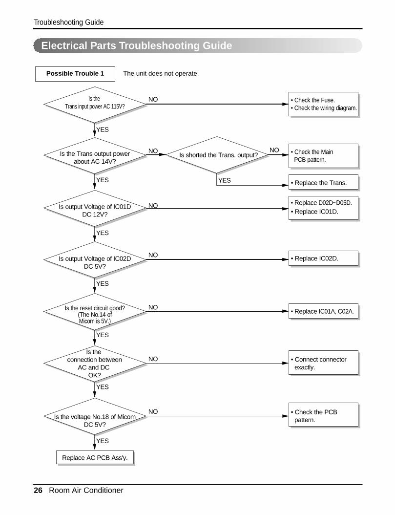
Is the Trans input power AC 115V?
Is the Trans output powerabout AC 14V?
Is shorted the Trans. output?
Is output Voltage of IC01DDC 12V?
Is output Voltage of IC02DDC 5V?
Is the voltage No.18 of MicomDC 5V?
Replace AC PCB Ass'y.
Is the connection between
AC and DC OK?
Is the reset circuit good?(The No.14 ofMicom is 5V.)
• Check the Fuse.• Check the wiring diagram.
• Check the Main PCB pattern.
• Replace the Trans.
• Replace D02D~D05D.• Replace IC01D.
• Replace IC02D.
• Replace IC01A, C02A.
• Connect connector exactly.
• Check the PCB pattern.
NO
NO
NO
NO
NO
NO
NO
YES
YES
YES
YES
YES
YES
YES
NO
YES
Possible Trouble 1 The unit does not operate.
Electrical Parts Troubleshooting Guide

Service Manual 27
Troubleshooting Guide
Possible Trouble 2 The compressor does not operate.
Possible Trouble 3 The compressor always operate.
Is setting Temp. set lower than Room
Temp.-0.5°C?
Is the voltage No.10of IC01M 0V?
• Replace IC01M.
• Select the setting Temp. to lower Number.
• Wait 3 Minutes.
Does the Unit delayfor 3 minutes?
• Replace MAIN PCB Ass'y.
Is the voltage N0.9 of IC01M DC 12V?
• Check the RY-COMP.• Check the wiring Diagram.
NO
NO
NO
YES YES
YES
YES
Is the wire connection of RY-COMP OK?
• Check the RY-COMP.
• Connect LEAD Wire to RY-COMP again.
NO
YES
NO
28 Room Air Conditioner
Troubleshooting Guide
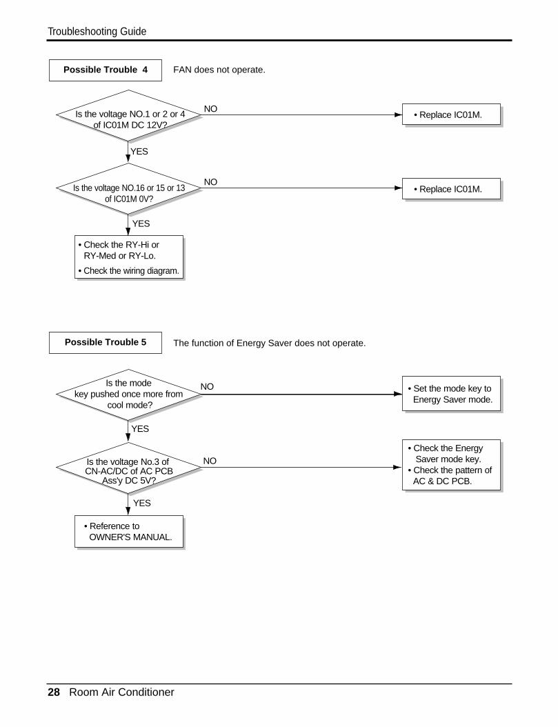
Possible Trouble 4 FAN does not operate.
Possible Trouble 5 The function of Energy Saver does not operate.
• Replace IC01M.
• Replace IC01M.
Is the voltage NO.1 or 2 or 4of IC01M DC 12V?
Is the voltage NO.16 or 15 or 13of IC01M 0V?
• Check the RY-Hi orRY-Med or RY-Lo.
• Check the wiring diagram.
NO
NO
YES
YES
NO
NO
YES
YES
Is the mode key pushed once more from
cool mode?
Is the voltage No.3 of CN-AC/DC of AC PCB
Ass'y DC 5V?
• Reference to OWNER'S MANUAL.
• Set the mode key to Energy Saver mode.
• Check the Energy Saver mode key.• Check the pattern of AC & DC PCB.
Service Manual 29
Troubleshooting Guide
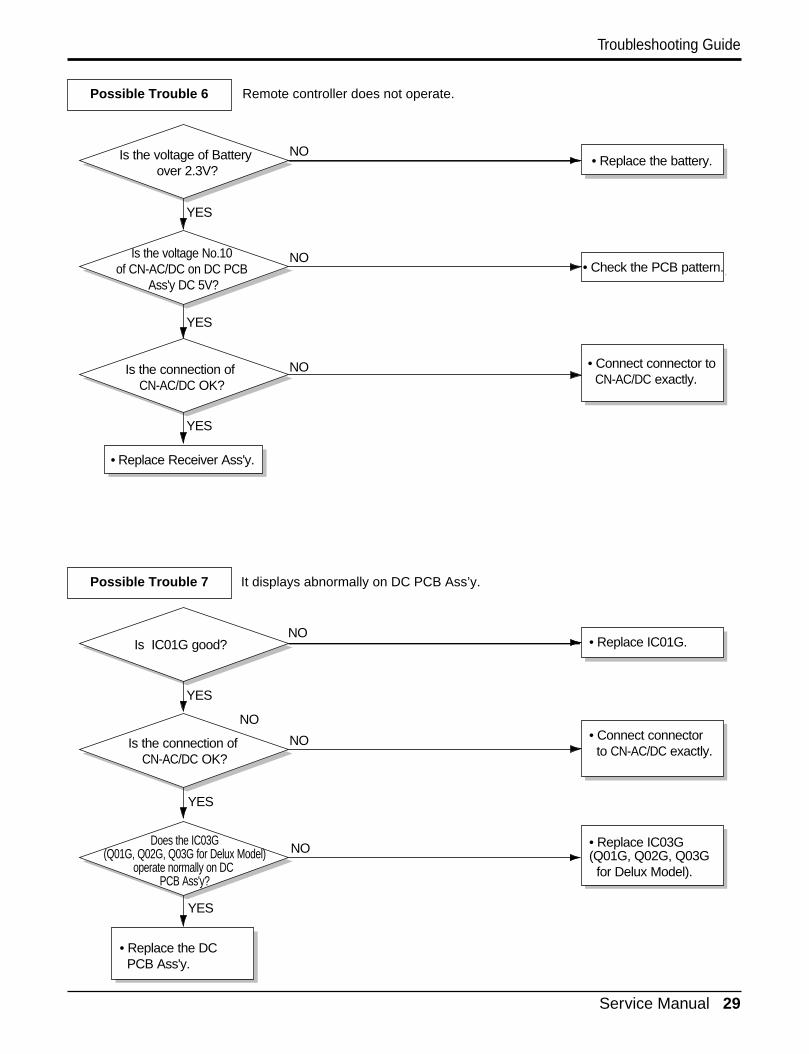
Possible Trouble 6 Remote controller does not operate.
Possible Trouble 7 It displays abnormally on DC PCB Ass’y.
NO
NO
NO
NO
YES
YES
YES
Is IC01G good?
Is the connection of CN-AC/DC OK?
• Replace the DC PCB Ass'y.
• Replace IC01G.
• Replace IC03G(Q01G, Q02G, Q03G for Delux Model).
• Connect connector to CN-AC/DC exactly.
Does the IC03G(Q01G, Q02G, Q03G for Delux Model)
operate normally on DC PCB Ass'y?
• Check the PCB pattern.
Is the voltage of Battery over 2.3V?
• Replace Receiver Ass'y.
Is the connection of CN-AC/DC OK?
Is the voltage No.10 of CN-AC/DC on DC PCB
Ass'y DC 5V?
• Replace the battery.
• Check the PCB pattern.
• Connect connector to CN-AC/DC exactly.
NO
NO
NO
YES
YES
YES
30 Room Air Conditioner
Troubleshooting Guide
• Check the Fuse.• Check the wiring diagram.
Is the Trans input power AC 115V?
Is the Trans output powerabout AC 14V?
Is shorted the Trans. output?
Is output Voltage of IC01DDC 12V?
Is output Voltage of IC02DDC 5V?
Is the voltage No.40 of MicomDC 5V?
Replace AC PCB Ass'y.
Is the connection between
AC and DC OK?
Is the reset circuit OK?(The No.14 ofMicom is 5V.)
• Check the Fuse.• Check the wiring diagram.
• Check the AC PCB pattern.
• Replace the Trans.
• Replace D02D~D05D.• Replace IC01D.
• Replace IC02D.
• Replace IC01A, C01A.
• Connect connector exactly.
• Check the PCB pattern.
NO
NO
NO
NO
NO
NO
NO
YES
YES
YES
YES
YES
YES
YES
NO
YES
Possible Trouble 1 The unit does not operate.
Electrical Parts
Service Manual 31
Troubleshooting Guide
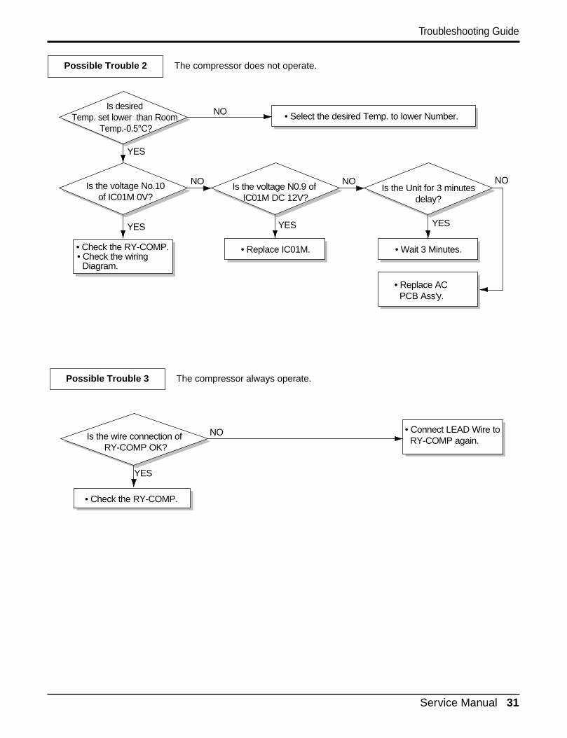
Possible Trouble 2 The compressor does not operate.
Possible Trouble 3 The compressor always operate.
Is desired Temp. set lower than Room
Temp.-0.5°C?
Is the voltage No.10of IC01M 0V?
• Replace IC01M.
• Select the desired Temp. to lower Number.
• Wait 3 Minutes.
Is the Unit for 3 minutesdelay?
• Replace AC PCB Ass'y.
Is the voltage N0.9 of IC01M DC 12V?
• Check the RY-COMP.• Check the wiring Diagram.
NO
NO
NO
YES YES
YES
YES
Is the wire connection of RY-COMP OK?
• Check the RY-COMP.
• Connect LEAD Wire to RY-COMP again.
NO
YES
NO
32 Room Air Conditioner
Troubleshooting Guide
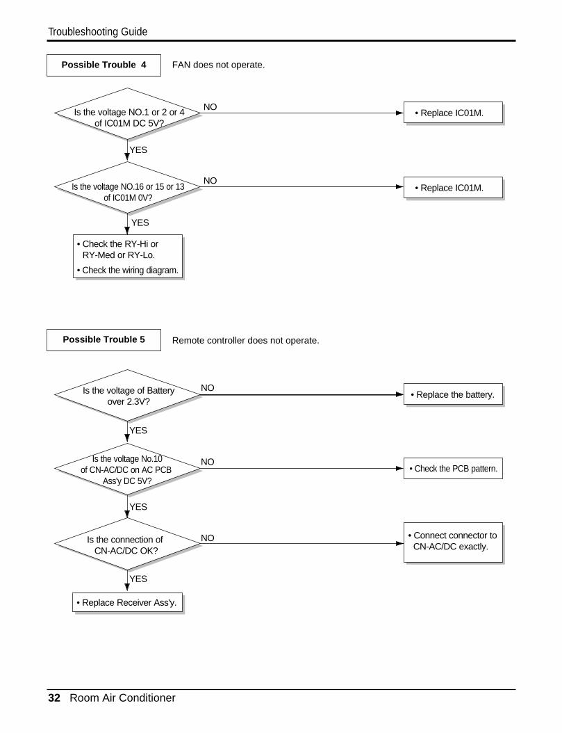
Possible Trouble 4 FAN does not operate.
Possible Trouble 5 Remote controller does not operate.
• Replace IC01M.
• Replace IC01M.
Is the voltage NO.1 or 2 or 4of IC01M DC 5V?
Is the voltage NO.16 or 15 or 13of IC01M 0V?
• Check the RY-Hi orRY-Med or RY-Lo.
• Check the wiring diagram.
NO
NO
YES
YES
• Check the PCB pattern.
Is the voltage of Batteryover 2.3V?
• Replace Receiver Ass'y.
Is the connection of CN-AC/DC OK?
Is the voltage No.10of CN-AC/DC on AC PCB
Ass'y DC 5V?
• Replace the battery.
• Check the PCB pattern.
• Connect connector to CN-AC/DC exactly.
NO
NO
NO
YES
YES
YES
Service Manual 33
Troubleshooting Guide
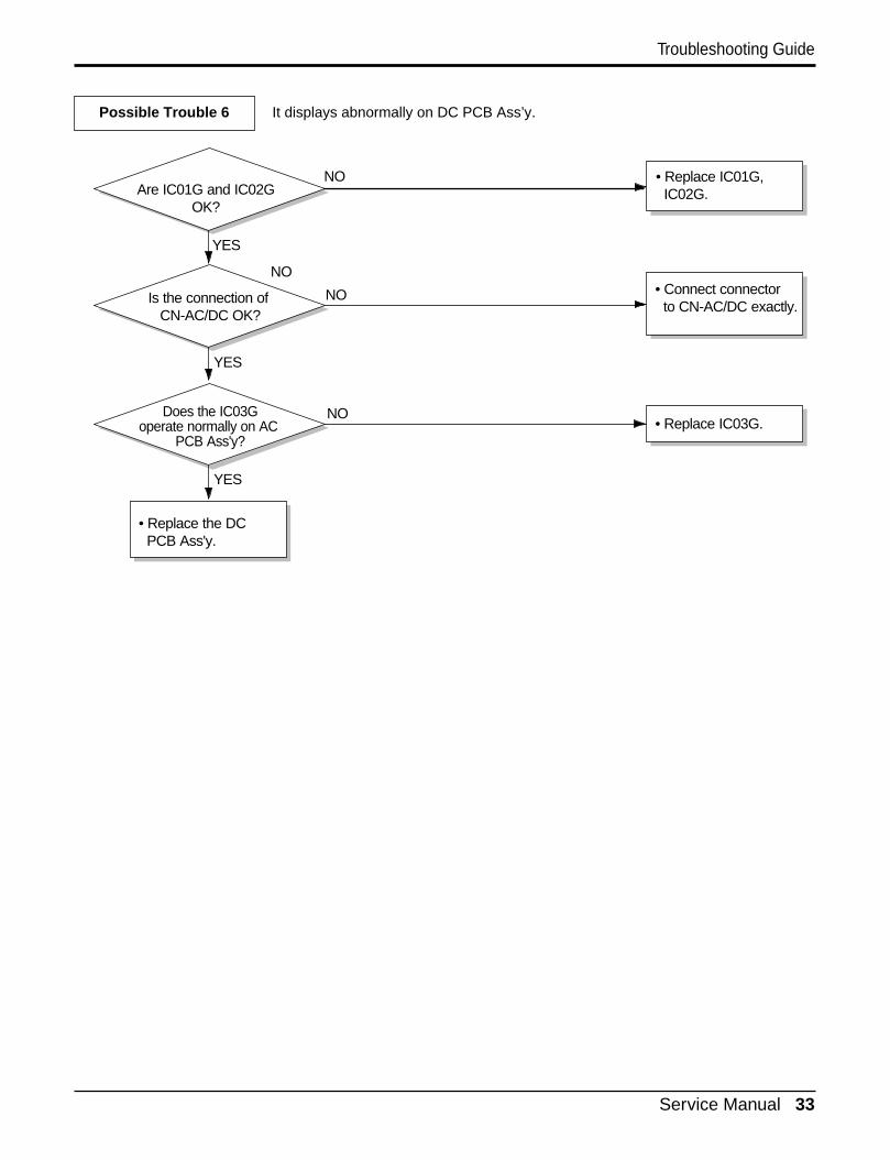
Possible Trouble 6 It displays abnormally on DC PCB Ass’y.
NO
NO
NO
NO
YES
YES
YES
Are IC01G and IC02GOK?
Is the connection of CN-AC/DC OK?
• Replace the DC PCB Ass'y.
• Replace IC01G, IC02G.
• Replace IC03G.
• Connect connector to CN-AC/DC exactly.
Does the IC03Goperate normally on AC
PCB Ass'y?
34 Room Air Conditioner
Troubleshooting Guide
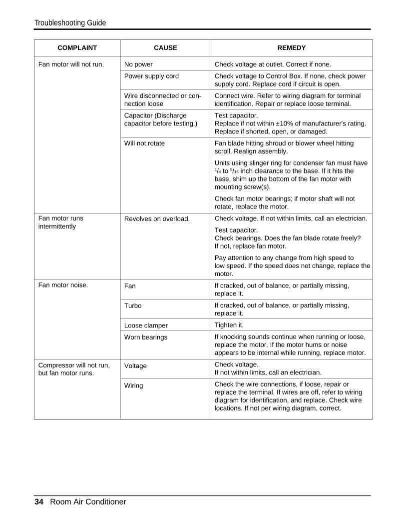
COMPLAINT CAUSE REMEDY
Check voltage at outlet. Correct if none.
Check voltage to Control Box. If none, check powersupply cord. Replace cord if circuit is open.
Connect wire. Refer to wiring diagram for terminalidentification. Repair or replace loose terminal.
Test capacitor.Replace if not within ±10% of manufacturer's rating.Replace if shorted, open, or damaged.
Fan blade hitting shroud or blower wheel hittingscroll. Realign assembly.
Units using slinger ring for condenser fan must have1/4 to 5/16 inch clearance to the base. If it hits thebase, shim up the bottom of the fan motor withmounting screw(s).
Check fan motor bearings; if motor shaft will notrotate, replace the motor.
Check voltage. If not within limits, call an electrician.
Test capacitor.Check bearings. Does the fan blade rotate freely?If not, replace fan motor.
Pay attention to any change from high speed tolow speed. If the speed does not change, replace themotor.
If cracked, out of balance, or partially missing,replace it.
If cracked, out of balance, or partially missing,replace it.
Tighten it.
If knocking sounds continue when running or loose,replace the motor. If the motor hums or noiseappears to be internal while running, replace motor.
Check voltage. If not within limits, call an electrician.
Check the wire connections, if loose, repair orreplace the terminal. If wires are off, refer to wiringdiagram for identification, and replace. Check wirelocations. If not per wiring diagram, correct.
No power
Power supply cord
Wire disconnected or con-nection loose
Capacitor (Dischargecapacitor before testing.)
Will not rotate
Revolves on overload.
Fan
Turbo
Loose clamper
Worn bearings
Voltage
Wiring
Fan motor will not run.
Fan motor runs intermittently
Fan motor noise.
Compressor will not run,but fan motor runs.
Service Manual 35
Troubleshooting Guide
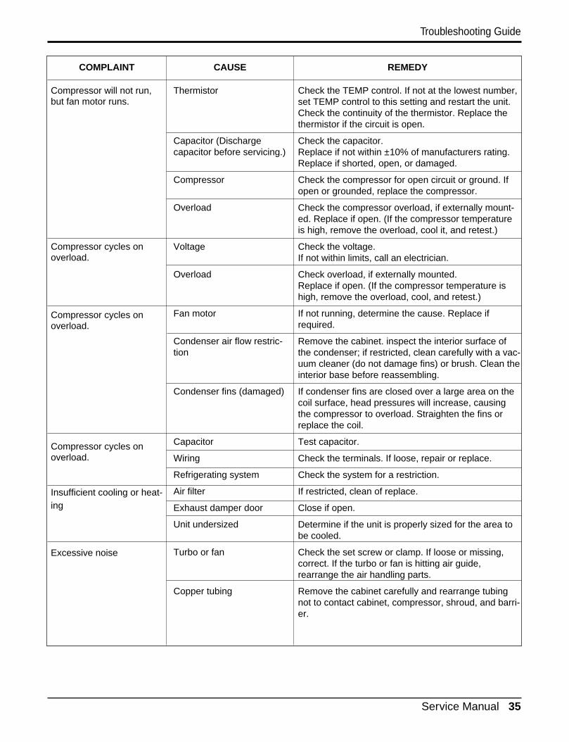
COMPLAINT CAUSE REMEDY
Check the TEMP control. If not at the lowest number,set TEMP control to this setting and restart the unit. Check the continuity of the thermistor. Replace thethermistor if the circuit is open.
Check the capacitor.Replace if not within ±10% of manufacturers rating.Replace if shorted, open, or damaged.
Check the compressor for open circuit or ground. Ifopen or grounded, replace the compressor.
Check the compressor overload, if externally mount-ed. Replace if open. (If the compressor temperatureis high, remove the overload, cool it, and retest.)
Check the voltage.If not within limits, call an electrician.
Check overload, if externally mounted.Replace if open. (If the compressor temperature ishigh, remove the overload, cool, and retest.)
If not running, determine the cause. Replace ifrequired.
Remove the cabinet. inspect the interior surface ofthe condenser; if restricted, clean carefully with a vac-uum cleaner (do not damage fins) or brush. Clean theinterior base before reassembling.
If condenser fins are closed over a large area on thecoil surface, head pressures will increase, causingthe compressor to overload. Straighten the fins orreplace the coil.
Test capacitor.
Check the terminals. If loose, repair or replace.
Check the system for a restriction.
If restricted, clean of replace.
Close if open.
Determine if the unit is properly sized for the area tobe cooled.
Check the set screw or clamp. If loose or missing,correct. If the turbo or fan is hitting air guide,rearrange the air handling parts.
Remove the cabinet carefully and rearrange tubingnot to contact cabinet, compressor, shroud, and barri-er.
Thermistor
Capacitor (Dischargecapacitor before servicing.)
Compressor
Overload
Voltage
Overload
Fan motor
Condenser air flow restric-tion
Condenser fins (damaged)
Capacitor
Wiring
Refrigerating system
Air filter
Exhaust damper door
Unit undersized
Turbo or fan
Copper tubing
Compressor will not run,but fan motor runs.
Compressor cycles onoverload.
Compressor cycles onoverload.
Compressor cycles onoverload.
Insufficient cooling or heat-ing
Excessive noise
36 Room Air Conditioner
Exploded View
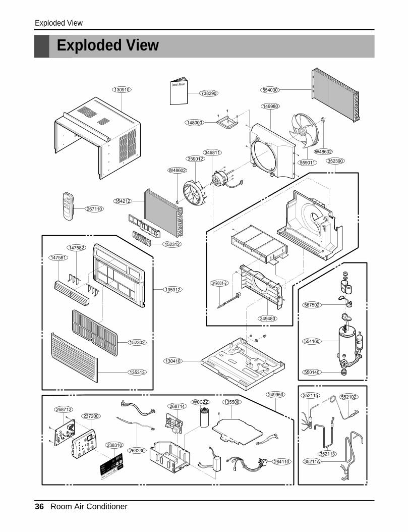
Exploded View
130910
149980
346811359012
W48602
349001-2
268714268712
238310
W0CZZ 135500
249950
147581
147582
559011
349480
552102
352113
352115
263230
237200
W48602
352390
148000
354212
267110
152312
152302
264110
130410
550140
35211A
554160
567502
135312
135313
554030Owner's Manual
738290
Service Manual 37
Replacement Parts List
Replacement Parts List
R
R
R
R
R
R
R
R
R
R
R
R
R
R
R
R
R
R
R
R
R
R
R
R
R
R
R
R
R
R
R
R
R
R
R
R
R
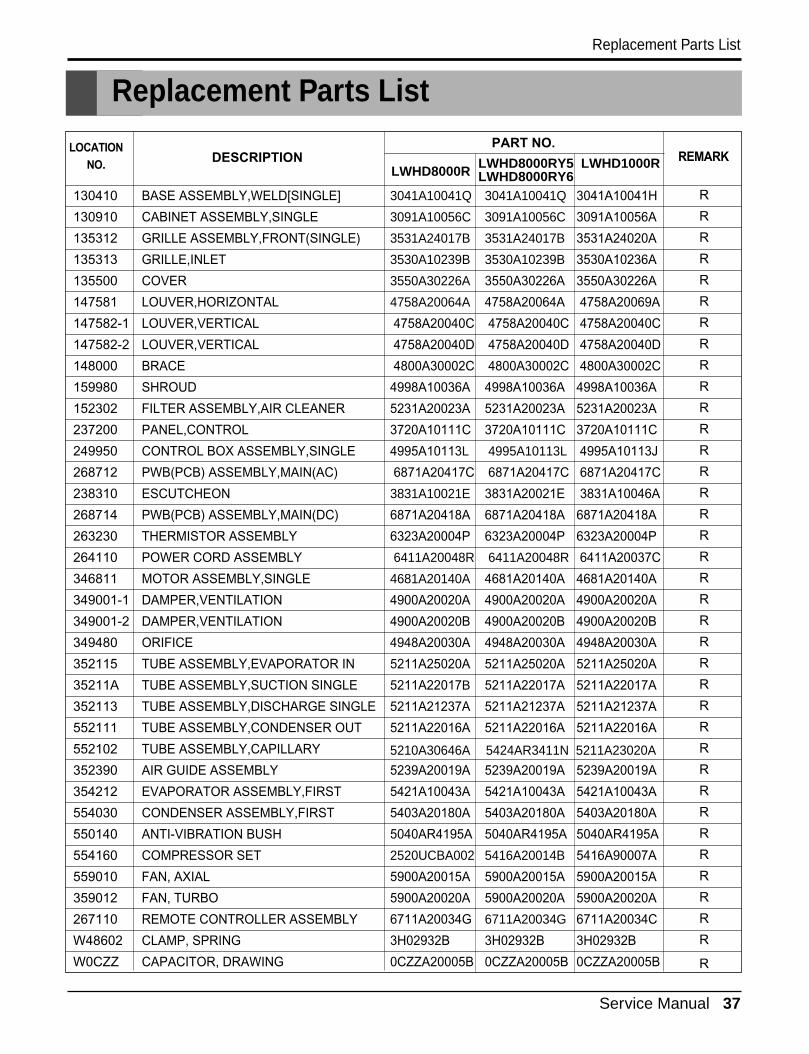
DESCRIPTIONPART NO.
REMARKLOCATION
NO.
130410
130910
135312
135313
135500
147581
147582-1
147582-2
148000
159980
152302
237200
249950
268712
238310
268714
263230
264110
346811
349001-1
349001-2
349480
352115
35211A
352113
552111
552102
352390
354212
554030
550140
554160
559010
359012
267110
W48602
W0CZZ
BASE ASSEMBLY,WELD[SINGLE]
CABINET ASSEMBLY,SINGLE
GRILLE ASSEMBLY,FRONT(SINGLE)
GRILLE,INLET
COVER
LOUVER,HORIZONTAL
LOUVER,VERTICAL
LOUVER,VERTICAL
BRACE
SHROUD
FILTER ASSEMBLY,AIR CLEANER
PANEL,CONTROL
CONTROL BOX ASSEMBLY,SINGLE
PWB(PCB) ASSEMBLY,MAIN(AC)
ESCUTCHEON
PWB(PCB) ASSEMBLY,MAIN(DC)
THERMISTOR ASSEMBLY
POWER CORD ASSEMBLY
MOTOR ASSEMBLY,SINGLE
DAMPER,VENTILATION
DAMPER,VENTILATION
ORIFICE
TUBE ASSEMBLY,EVAPORATOR IN
TUBE ASSEMBLY,SUCTION SINGLE
TUBE ASSEMBLY,DISCHARGE SINGLE
TUBE ASSEMBLY,CONDENSER OUT
TUBE ASSEMBLY,CAPILLARY
AIR GUIDE ASSEMBLY
EVAPORATOR ASSEMBLY,FIRST
CONDENSER ASSEMBLY,FIRST
ANTI-VIBRATION BUSH
COMPRESSOR SET
FAN, AXIAL
FAN, TURBO
REMOTE CONTROLLER ASSEMBLY
CLAMP, SPRING
CAPACITOR, DRAWING
3041A10041Q
3091A10056C
3531A24017B
3530A10239B
3550A30226A
4758A20064A
4758A20040C
4758A20040D
4800A30002C
4998A10036A
5231A20023A
3720A10111C
4995A10113L
6871A20417C
3831A10021E
6871A20418A
6323A20004P
6411A20048R
4681A20140A
4900A20020A
4900A20020B
4948A20030A
5211A25020A
5211A22017B
5211A21237A
5211A22016A
5239A20019A
5421A10043A
5403A20180A
5040AR4195A
2520UCBA002
5900A20015A
5900A20020A
6711A20034G
3H02932B
0CZZA20005B
3041A10041Q
3091A10056C
3531A24017B
3530A10239B
3550A30226A
4758A20064A
4758A20040C
4758A20040D
4800A30002C
4998A10036A
5231A20023A
3720A10111C
4995A10113L
6871A20417C
3831A20021E
6871A20418A
6323A20004P
6411A20048R
4681A20140A
4900A20020A
4900A20020B
4948A20030A
5211A25020A
5211A22017A
5211A21237A
5211A22016A
5239A20019A
5421A10043A
5403A20180A
5040AR4195A
5416A20014B
5900A20015A
5900A20020A
6711A20034G
3H02932B
0CZZA20005B
3041A10041H
3091A10056A
3531A24020A
3530A10236A
3550A30226A
4758A20069A
4758A20040C
4758A20040D
4800A30002C
4998A10036A
5231A20023A
3720A10111C
4995A10113J
6871A20417C
3831A10046A
6871A20418A
6323A20004P
6411A20037C
4681A20140A
4900A20020A
4900A20020B
4948A20030A
5211A25020A
5211A22017A
5211A21237A
5211A22016A
5239A20019A
5421A10043A
5403A20180A
5040AR4195A
5416A90007A
5900A20015A
5900A20020A
6711A20034C
3H02932B
0CZZA20005B
LWHD8000R LWHD8000RY5 LWHD1000RLWHD8000RY6
5424AR3411N 5211A23020A5210A30646A

P/NO:3828A29003C January, 2005Printed in China