room in roof (‘rir’) trussed rafters - muir timber · pdf fileroom in roof...
TRANSCRIPT

ROOM IN ROOF ( ‘RIR ’) TRUSSED RAFTERS
The ‘Room-in-Roof’ (‘RiR’) or attic trussed
rafter is a simple means of providing the
structural roof and floor in the same
component. This offers considerable
advantages over other forms of living roof
construction:
• There need be no restrictions on lower floor layouts since
the trusses can clear span on to external walls although
greater spans and room widths can be achieved by
utilising internal loadbearing walls.
• ‘RiR’ trussed rafters are computer designed and factory
assembled units, resulting in better quality control.
• Complex, labour intensive site joints are not required.
• ‘RiR’ trussed rafters can be erected quickly, offering cost
savings and providing a weathertight shell earlier.
• Freedom to plan the room layout within the roof space.
• A complete structure is provided, ready to receive roof
finishes, plaster board and floorboarding.
Sheet No.1 May 2007P R O D U C T DATA S H E E T
Comparing an 8 metre span standard trussed rafter (see
opposite) with an equivalent 8 metre span ‘RiR’ truss, the
external members will increase in width and depth. There
are two reasons for this:
The ‘RiR’ truss supports approximately 60% more load than a
standard truss of the same span and pitch. This difference
in load is made up of plasterboard ceilings and wall
construction, full superimposed floor loading and floor
boarding.
Lack of triangulation in a ‘RiR’ truss is the second reason for
increased member sizes.
Predominantly 47mm thick timber is used, with member
depths ranging from 145mm to 245mm.
Weight of truss approx 55kg 35 x 97 ceiling tie
35 x 97 rafter
Weight of truss approx 125kg 47 x 197 ceiling joist
47 x 197 rafter
Fig. 1 Typical 8 metre span conventional trussed rafter
Fig. 2 Typical 8 metre span ‘Room in Roof’ trussed rafter
40°
40°

PA G E 2
Some basic guidelines to the construction of roofs from ‘Room in
Roof’ trusses are as follows:
Three-Bearing ‘RiR’ Trussed Rafters
For most purposes ‘RiR’ trussed rafters can be designed to clear span
between the front and rear walls of a dwelling thus avoiding the
need for building loadbearing walls and foundations on lower
storeys. However, if loadbearing walls exist or can easily be added
then they can be used to good effect to provide additional support
to the ‘RiR’ trusses. In this way greater room sizes are possible but
to be effective they should occur within the centre 20% of the truss
span and are most effective when placed near the mid-span of the
truss. See Fig. 3
Size of ‘RiR’ Trussed Rafters
Where possible keep the size of ‘RiR’ trussed rafters within the limits
dictated by safe transportation. There may be local conditions that
affect this but generally an overall height of truss of 4 metres is
easy to transport. If greater height is required then trusses may be
constructed in two parts. The two-part trusses will be structurally
joined on site and instructions for this will normally be provided by
the trussed rafter fabricator. This joint is often made with a
proprietary connector plate. Fig. 5 shows a typical two-part truss
arrangement
Some Typical ‘RiR’ Configurations
Fig. 4 gives some ideas on the size of loft rooms available from differing configurations of span and pitch of ‘RiR’ trusses (all room widths
shown in metres). These sketches are intended to show geometry of roofs at various spans and pitches and not structural details. In some
cases extra intermediate supports may be necessary to achieve these spans. Internal, intermediate members may be needed within the non-
habitable spaces of the trussed rafters on very large trusses and in some cases trusses may need to be produced in two parts. For clarity such
details have been omitted from the sketches.
Fig. 3 Three bearing
‘RiR’ trussed rafter
To be most effective the third support to be located in this zoneand as near to centre line as possible
Connection detail provided by the trussed rafter designer witheach truss design
Fig. 5 Two-part ‘RiR’
trussed rafters
Fig. 4 Some basic
configurations
NOT
SUITABLE
NOT
SUITABLE
NOT
SUITABLE
NOT
SUITABLE
Greater room widths possible
0.4L 0.4L0.2L
6m 7m 8m 9m 10m 11m
35°
40°
45°
50°
4.5 4.75 5.0
6.05.255.04.54.0
3.5 4.0 5.0 5.0 5.25 6.5
7.06.55.255.04.754.0

PA G E 3
Services in ‘RiR’ Trussed Rafters
The lower void area in ‘RiR’ trusses is an ideal location for services,
allowing lateral runs to be positioned between the bottom chords of
the trusses (see Fig. 6). Access to this void area and the service
runs can be made via a small hatch in the low level partition.
The lower member of the truss forms not only the floor joist for the
attic room but it also makes a vital contribution to the stability of
the whole roof. Under no circumstances should the floor joist of a
‘RiR’ trussed rafter be notched or drilled to accommodate services.
Layout of ‘RiR’ Trussed Rafters and Planning
Position of Openings
The application of a few basic principles at the concept stage of a
project can often result in substantial cost savings by maximising
the use of prefabricated components and minimising loose infill
areas. Try to locate opening in the roof to fit in with the normal
spacing of ‘RiR’ trussed rafters (usually 600mm). This can often
result in reducing the number of trussed rafters required
(see Fig. 7).
Dormer windows and stairwell openings are formed by placing
multiple trusses either side of the openings and framing the
resulting space with loose timbers. Placing stairwells parallel to
truss spans and ensuring that windows are positioned opposite each
other will make the overall roof design simpler and cheaper. Fig. 8
exemplifies the problems associated with misaligned roof features.
Bracing of ‘RiR’ Trussed Rafters
In common with all other trussed rafter roofs, ‘RiR’ trussed rafters
need to be braced. Special attention must be given to diagonal
bracing of the rafters since the space beneath them will form part of
the habitable space of the roof.
It is not possible to provide bracing details within the scope of this
Product Data Sheet but full details are given in the Trussed Rafter
Association’s Technical Handbook (‘Technical Handbook - Site
Installation Guide’, available from the Trussed Rafter Association).
Water Tanks in ‘RiR’ Trussed Rafter Roofs
Full details of supporting water tanks in ‘RiR’ trusses are given in
the ‘Technical Handbook’.
Fig. 6 Services in trussed rafter roofs
Fig. 7 Positioning of trussed rafter
Fig. 8 Positioning of roof features
✔
Unsuitable layout - very difficult to provide‘RiR’ trusses to support this roof since
windows and stairs all overlap
Suitable layout - since staircase parallel totrusses, windows directly opposite and small
widths may be site framed
✖

PA G E 4
Thermal Insulation
Thought should be given at an early stage to the type and position
of the thermal insulation since this could affect the size of rafter
required.
Shown below are two different arrangements for insulation within
the roof of a ‘Room in Roof’ trussed rafter construction. In both
cases an air gap of 50mm should be provided between the top of
the insulation and the underside of the roof covering. In addition
eaves level vents equivalent to a continuous 25mm gap must be
provided.
Fire Resistance
Under normal circumstances dwelling roofs are not required to have
fire resistance under UK Building Regulations. However, ’RiR‘ trussed
roofs are slightly different since the ceiling tie of the truss forms
the floor of the upper storey and, therefore, are controlled in exactly
the same way as any other intermediate house floor.
Where the ‘RiR’ forms the second storey of a dwelling then the floor
must provide a ‘modified’ 30 minute fire resistance. In the case
where the roof space forms the third storey then the floor must
provide a full 30 minute fire resistance.
The only formal guidance on roof construction is given in Approved
Document ‘Timber Intermediate Floors for Dwellings’ published by
TRADA. Fig. 11 shows the principle recommendations of the TRADA
AD.
As an alternative solution TRADA recommend a simpler form of
construction that satisfies both the ‘modified’ and full 30 minute
fire resistance requirements by employing a thicker or higher grade
of plasterboard to the ceiling beneath the floor. This is shown in
Fig. 12.
This information sheet gives a brief introduction to the use of
‘Room in Roof’ trussed rafters to form living accommodation in
the roof space of new dwellings. It is not intended to be
comprehensive and it is accepted that there may be many other
solutions to the various aspects of construction discussed. Readers
are advised to discuss their particular design situations with their
specialist trussed rafter supplier.
The guidelines contained within this information sheet are given
in good faith but without liability and its use shall be entirely at
the risk of the user.
T R U S S E D R A F T E R A S S O C I AT I O NP.O.Box 571
Chesterfield S40 9DH
Tel & Fax: 01246 230036
email:[email protected]
www.tra.org.uk
Fig. 9 Roof insulation -
alternative arrangement
Fig. 11 Requirements of TRADA Approved Document
Fig. 12 Alternative solution
*37mm is the absolute minimum thickness required where joists
form part of fire resisting constructions. Joists for ‘RiR’ trussed
rafters will normally be nominally 47mm thick
*
Fig. 9 Roof insulation

EXAMPLES OF BASIC
TRUSSED RAFTER PROFILES
Sheet No.2 May 2007P R O D U C T DATA S H E E T
King Post Queen Post Fink
Fan Double ‘W’ Small Cantilever
Large Single Cantilever Large Double Cantilever Assymetric
Monopitch ‘Room in Roof’ Assymetric ‘Room in Roof’
Dormer ‘Room in Roof’ Flat-top ‘Room in Roof’ Hip End
Open Jack Bobtail/Stub Double Bobtail/Stub

This information sheet gives an idea of some configurations available using trussed rafter technology. The configurations shown are not
intended to be solutions to specific design requirements and some types may be unsuitable for certain span conditions. However, they are
intended to show the flexibility of the system but readers are advised to discuss their particular design situations with their specialist trussed
rafter supplier. The guidelines contained within this information sheet are given in good faith but without liability and its use shall be
entirely at the risk of the user.
T R U S S E D R A F T E R A S S O C I AT I O NP.O.Box 571
Chesterfield S40 9DH
Tel & Fax: 01246 230036
email:[email protected]
www.tra.org.uk
AND MORE COMPLEX
TRUSSED RAFTER PROFILES
Raised Support Extended Joist Extended Rafter
Northlight Scissors Raised Ceiling
Inverted Gambrel/Mansard ‘Room in Roof’ Gambrel/Mansard
Parallel Chord Vaulted Cathedral
Special Profiles Portal Frame

Bearers vertically in line& at close centres
GUIDELINES FOR THE STORAGE AND
ERECTION OF TRUSSED RAFTERS ON SITE(PART 1)
Unloading Trussed Rafters
When a delivery of trussed rafters arrives on site the
contractor(s) involved should be prepared and have already
allocated sufficient and suitable resources to ensure the
trussed rafters are unloaded safely and in a manner so as not
to overstress or damage the trusses. This operation will have
been subject to a Contractors General Risk Assessment and
then detailed in a safe working method statement that has
been approved by the principal contractor or the person
responsible for Health and Safety on site. Normally, trussed
rafters will be delivered in tight bundles using bindings. This
will often require mechanical handling equipment, such as a
forklift or crane, to enable the safe manoeuvring of these large
units. The safe working method statement should
accommodate any special handling instructions or hazards
specified by the designer in his risk assessment for the truss
design.
Site Storage of Trussed Rafters
Trussed rafters can be safely stored vertically or horizontally at
ground level or on any other properly designed temporary
storage platform above ground level. Whichever method and
location is chosen the temporary support should be set out to
ensure that the units do not make direct contact with the
ground or any vegetation and be so arranged as to prevent any
distortion.
The delivery of trussed rafters should, wherever possible, be
organised to minimise site storage time; however, where
longer periods of storage are anticipated then the trusses
should be protected with covers fixed in such a way as to
allow proper ventilation around the trusses.
When stored vertically bearers should be positioned at the
locations where support has been assumed to be provided in
the design with stacking carried out against a firm and safe
support or by using suitable props (Fig. 1)
When trusses are stored horizontally level bearers should be
positioned beneath each truss node (minimum) to prevent any
deformation and distortion (Fig. 2). No other method of
storing trussed rafters is considered to be suitable, except
where specific provision has been made in the design for an
alternative temporary support load case.
Sheet No.3 May 2007P R O D U C T DATA S H E E T
Fig. 2 Safe horizontal storage
Fig. 3 Safe method of breaking a bundle of trusses
Trestle prop
Bearer height to allow overhang to clear ground
Trestle prop
Ensure that the battens are fixed to each truss prior to release of the bindings
Fig. 1 Safe vertical storage

PA G E 2
Extreme care should be exercised when removing the bindings from a
bundle of trusses. As a precaution against destabilisation of the
whole bundle of trusses, it is recommended that prior to the removal
of the bands, timber battens are fixed across the bundle at several
locations with a part driven nail into every truss. Such a simple
precaution will allow the safe removal of single trusses once the
bands are removed. A suggested arrangement of batten locations for
a standard Fink truss is shown in Fig. 3.
Alternative details relating to this procedure and which involve the
unbundling of the trusses whilst on the back of the lorry should be
communicated by the contractor to the truss manufacturer prior to
their delivery to site.
Erection Procedure for Simple Domestic Roofs
The following gives guidance on a typical erection sequence for a
simple domestic type roof:
Step 1
Ensure wall plates are level and adequately secured to load bearing
walls. Mark off positions of trusses along both plates.
Step 2
Either mechanically or manually lift the first truss up to the roof
holding it in a vertical plane, as far as possible, at all times. Erect
the first truss (Fig. 4) in such a way that it coincides with the
position of the end of the rafter diagonal bracing when fitted.
Temporarily brace first truss to both wall plates.
Step 3
Erect second truss ensuring that its production face matches the
first truss as indicated by the labels or markings affixed to the truss.
Then brace back to first truss with temporary horizontal battens
along the rafters and, if necessary, ceiling tie members (Fig. 5).
Step 4
After checking for vertical, erect remaining trusses towards gable
end ensuring correct orientation of common manufacturing faces as
described above.
Step 5
Fix the permanent diagonal braces (Fig. 6) which should be at
approximately 45° to final position of tile battens and fixed as high
up the first truss as possible and nailed to the wall plate the other
end. All permanent braces should be min 22 x 97mm timber and
fixed with 2 no. 3.35mm dia. x 75mm long galvanized nails to each
truss. Braces may be lap jointed providing the lap spans at least two
trusses.
Step 6
Fix remaining longitudinal bracing to rafters, struts and ceiling ties
as shown in Fig. 6. Note that all bracing is repeated for both sides
of roof.
Step 7
All remaining longitudinal diagonal and chevron bracing specified for
the roof should now be fixed together with galvanized metal
retaining straps to walls and gable ends.
Step 8
Temporary bracing should now be removed and any additional trusses
erected using the completed section of the roof as a means of
temporarily bracing them.
Step 9
After erection and before felting and battening the roof, check that
all trusses are aligned vertically and each truss is restrained from
bowing out of its vertical plane.
Important:
Trusses must never be cut or adjusted in any way without prior
consultation with the roof truss designers. If site circumstances
make modification unavoidable then changes should only ever be
made with the prior knowledge and consent of the trussed rafter
designer.
Fig. 4
Fig. 5
Fig. 6
Bearer ‘a’ placed as close tonode point as possible
Span of trusses L s
Tank placed centrally
Bay size
Node point
PA G E 3
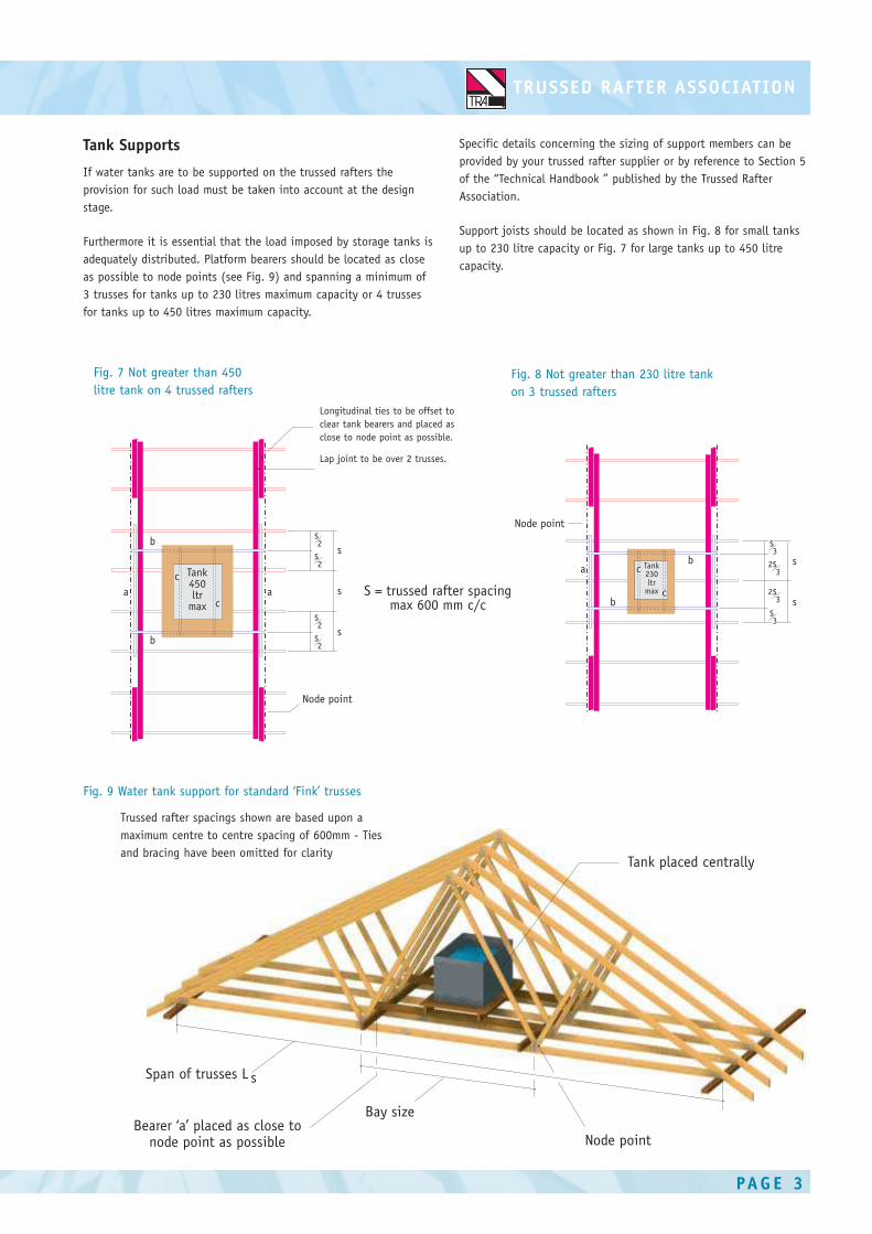
Tank Supports
If water tanks are to be supported on the trussed rafters the
provision for such load must be taken into account at the design
stage.
Furthermore it is essential that the load imposed by storage tanks is
adequately distributed. Platform bearers should be located as close
as possible to node points (see Fig. 9) and spanning a minimum of
3 trusses for tanks up to 230 litres maximum capacity or 4 trusses
for tanks up to 450 litres maximum capacity.
Specific details concerning the sizing of support members can be
provided by your trussed rafter supplier or by reference to Section 5
of the “Technical Handbook ” published by the Trussed Rafter
Association.
Support joists should be located as shown in Fig. 8 for small tanks
up to 230 litre capacity or Fig. 7 for large tanks up to 450 litre
capacity.
s
s
Tank230ltr
max c
c
b
ba
Node point
s3
s3
2s3
2s3
S = trussed rafter spacingmax 600 mm c/c
Tank450ltr
max
bs
s
s
c
c
b
a a
Node point
s2
s2
s2
s2
Fig. 7 Not greater than 450
litre tank on 4 trussed rafters
Longitudinal ties to be offset to
clear tank bearers and placed as
close to node point as possible.
Lap joint to be over 2 trusses.
Fig. 8 Not greater than 230 litre tank
on 3 trussed rafters
Fig. 9 Water tank support for standard ‘Fink’ trusses
Trussed rafter spacings shown are based upon a
maximum centre to centre spacing of 600mm - Ties
and bracing have been omitted for clarity
PA G E 4
This information sheet gives a brief introduction to the storage and erection of trussed rafters on site for a simple house roof. Other
more detailed information will follow in this series of Product Data Sheets. It is not intended to be comprehensive and it is accepted
that there may be many other solutions to the various aspects of construction discussed. Readers are advised to discuss their particular
design situations with their specialist trussed rafter supplier.
The guidelines contained within this information sheet are given in good faith but without liability and its use shall be entirely at the
risk of the user.
Further detailed reading on erection and bracing methods can be found in the ‘Technical Handbook’ available from the Trussed Rafter
Association.
T R U S S E D R A F T E R A S S O C I AT I O NP.O.Box 571
Chesterfield S40 9DH
Tel & Fax: 01246 230036
email:[email protected]
www.tra.org.uk
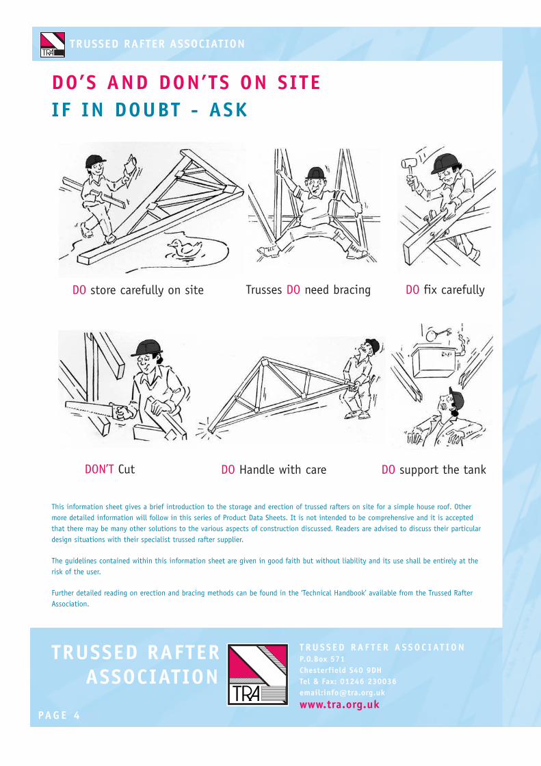
DO store carefully on site
DO’S AND DON’TS ON SITE
IF IN DOUBT - ASK
Trusses DO need bracing DO fix carefully
DON’T Cut DO Handle with care DO support the tank

STANDARD BRACING OF SIMPLE
DUOPITCHED TRUSSED RAFTER ROOFS
FOR DWELLINGS
Why brace trussed rafter roofs?
Trussed rafters must be braced to create a rigid and stable
roof structure. If the bracing is omitted, wrongly positioned
or badly fixed, it may result in distortion or failure of
individual trusses or in some instances the whole roof.
Bracing Responsibility
The Building Designer and not the trussed rafter supplier is
responsible for designing and detailing all elements of roof
bracing required in the roof including any bracing required
by the truss designer in order to provide lateral restraint to
truss members. The Trussed Rafter Designer will inform the
Building Designer of any truss integrity bracing required, eg
compression web braces.
This product Data Sheet shows a astandard method of
bracing to provide roof stability for spans up to 12m.
BS5268-3 Annex A gives details on bracing trusses up to
17m.
The system of bracing reproduced in this Data Sheet may be
used without any further calculations, provided that the
limitations summarised are met in full.
The Functions of Roof Bracing
Roof bracing performs three distinct functions:
Temporary bracing This is used to restrain the trusses
during erection. See Product Data Sheet No.3 for more
information.
Truss Stability bracing This is permanent bracing which
holds the trusses upright, straight and prevents any out-of-
plane buckling of the members.
Wind or wall bracing This bracing is installed in the roof in
addition to the truss stability bracing and its purpose is to
stabilise the gable walls under the action of wind loading.
Sheet No.4 February 2011PRODUC T DATA SH E E T
Fig. 1 The elements of roof bracing
During the erection process Temporary Bracing is
used to restrain the trussed rafters until it is
possible to install permanent bracing
Longitudinal
Binders
Longitudinal
Binders
Chevron BraceChevron Brace
Gable Wall
Diagonal Wind Brace
Truss
Temporary Brace
Trusses @ max. 600mm centres
PAG E 2
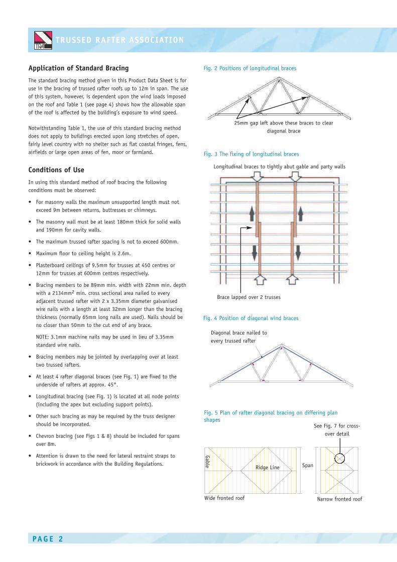
Application of Standard Bracing
The standard bracing method given in this Product Data Sheet is for
use in the bracing of trussed rafter roofs up to 12m in span. The use
of this system, however, is dependent upon the wind loads imposed
on the roof and Table 1 (see page 4) shows how the allowable span
of the roof is affected by the building’s exposure to wind speed.
Notwithstanding Table 1, the use of this standard bracing method
does not apply to buildings erected upon long stretches of open,
fairly level country with no shelter such as flat coastal fringes, fens,
airfields or large open areas of fen, moor or farmland.
Conditions of Use
In using this standard method of roof bracing the following
conditions must be observed:
• For masonry walls the maximum unsupported length must not
exceed 9m between returns, buttresses or chimneys.
• The masonry wall must be at least 180mm thick for solid walls
and 190mm for cavity walls.
• The maximum trussed rafter spacing is not to exceed 600mm.
• Maximum floor to ceiling height is 2.6m.
• Plasterboard ceilings of 9.5mm for trusses at 450 centres or
12mm for trusses at 600mm centres respectively.
• Bracing members to be 89mm min. width with 22mm min. depth
with a 2134mm2 min. cross sectional area nailed to every
adjacent trussed rafter with 2 x 3.35mm diameter galvanised
wire nails with a length at least 32mm longer than the bracing
thickness (normally 65mm long nails are used). Nails should be
no closer than 50mm to the cut end of any brace.
NOTE: 3.1mm machine nails may be used in lieu of 3.35mm
standard wire nails.
• Bracing members may be jointed by overlapping over at least
two trussed rafters.
• At least 4 rafter diagonal braces (see Fig. 1) are fixed to the
underside of rafters at approx. 45°.
• Longitudinal bracing (see Fig. 1) is located at all node points
(including the apex but excluding support points).
• Other such bracing as may be required by the truss designer
should be incorporated.
• Chevron bracing (see Figs 1 & 8) should be included for spans
over 8m.
• Attention is drawn to the need for lateral restraint straps to
brickwork in accordance with the Building Regulations.
25mm gap left above these braces to clear
diagonal brace
Fig. 2 Positions of longitudinal braces
Fig. 3 The fixing of longitudinal braces
Longitudinal braces to tightly abut gable and party walls
Brace lapped over 2 trusses
Fig. 4 Position of diagonal wind braces
Diagonal brace nailed to
every trussed rafter
Fig. 5 Plan of rafter diagonal bracing on differing plan
shapesSee Fig. 7 for cross-
over detail
Narrow fronted roofWide fronted roof
Gab
le
Ridge Line Span

PAG E 3
Other considerations
If an insulation material is installed on top of the rafters it may
reduce the effect of the tiling batten restraint to rafters. Additional
bracing may, therefore, be required underneath the rafter as
specified by the truss designer.
Plasterboard should be fixed directly to the face of the ceiling tie
members of the trussed rafters or continuous counter battens.
Where plasterboard is omitted the ceiling tie members need to be
braced at all nodes and one or more additional longitudinal brace
may be required in the bays as determined by the trussed rafter
design. Diagonal bracing in the outer ceiling tie bays should also be
fixed at 45degrees and extend the length of the building.
Chevron bracing
Chevron bracing is needed to ensure stability on duopitch roof spans
over 8m and monopitch roof spans over 5m span. The arrangement
of the braces are shown in Fig. 8.
Braces need not overlap along the roof and one or two trussed
rafters may be left (at position A in Fig. 8) between the ends of
adjacent braces. Braces should be at about 45 degrees and be nailed
to at least 3 trussed rafters.
Roof sarking
Where approved sarking materials are directly fixed to the top face
of the rafter members, it is permissible to omit the rafter diagonal
bracing, chevron bracing on webs and longitudinal bracing at rafter
level.
Sarking / Sheathing material must be moisture resistant and provide
an adequate level of restraint to out-of-plane buckling and wind
forces. See BS5268-3 for more information on suitable materials.
Diagonal bracing should be fixed to the wallplate in accordance with
BS 5268-3.
Fig. 6 Plan of rafter diagonal bracing arrangement on a
wide fronted roof
Rid
ge
Alternative direction of diagonal bracing
Fig. 7 Splicing of intersecting diagonal braces and end
jointing
22 x 97 x 600mm long
timber splice plate nailed
using min. of 4 x 3.35mm
x 65 mm long galvanised
wire nails each side driven
through and clenched
Brace length lap jointed over at least
two trusses if necessary
Ideally 4
5deg
+ or -1
0 deg
Fig. 8 Alternative fixing arrangement for chevron braces
(truss span over 8m)
A
A
3
2
4
1
1. Ideally 45 degrees but
no less than 35° or
greater than 55°.
2. Nailed to wall plate.
3. Rafter diagonal brace
lap jointed if required.
4.Wall plate.
Rafter brace nailed to
wall plate.

PAG E 4
This information sheet gives a summary of the standard bracing requirements given in BS 5268-3. All the information given here should
be read in conjunction with the requirements of that standard. The guidelines contained within this information sheet are given in good
faith but without liability and its use shall be entirely at the risk of the user.
For more information on the bracing of trussed rafter roofs readers are recommended to study BS 5268 - 3, “Structural use of timber -
Code of practice for trussed rafter roofs” available from the British Standards Institution. Figure A4 from BS 5268-3 is reproduced with
the permission of BSI under licence number 2002SK/0190. British Standards can be obtained from BSI Customer Services, 389 Chiswick
High Road, London W4 4AL. (Tel + 44 (0) 20 8996 9001).
Further detailed reading on bracing methods can also be found in the ‘Technical Handbook’ available from the Trussed Rafter Association.
T RU S S E D R A F T E R A S S O C I AT I ONThe Building Centre, 26 Store Street,
London WC1E 7BT
Tel: 020 3205 0032
email:[email protected]
www.tra.org.uk
Fig. 9 Basic wind zonesTable 1 Limiting spans for standard bracing

STANDARD BRACING OF ‘ROOM IN THE
ROOF’ (ATTIC) TRUSSED RAFTER ROOFS
Why brace trussed rafter roofs?
Trussed rafters must be braced to create a rigid and stable roof
structure. If the bracing is omitted, wrongly positioned or badly
fixed, it may result in distortion or failure of individual trusses
or in some instances the whole roof.
Bracing Responsibility
The Building Designer, and not the trussed rafter supplier, is
responsible for designing and detailing all elements of roof
bracing required in the roof, including any bracing required by
the Trussed Rafter Designer in order to provide lateral restraint
to truss members. The Trussed Rafter Designer will inform the
Building Designer of any truss integrity bracing required, eg
compression web braces.
The bracing system highlighted in this Product Data Sheet
shows a standard method of providing roof stability for spans up
to 12m in accordance with BS 5268-3, ‘Code of practice for
trussed rafter roofs’.
The system of bracing reproduced in this Data Sheet may be
used without any further calculations, provided that the
limitations summarised are met in full.
The Functions of Roof Bracing
Roof bracing performs three distinct functions:
Temporary bracing
This is used to restrain the trusses during erection. See Product
Data Sheet No.3 for more information.
Truss Stability bracing
This is permanent bracing which holds the trusses upright,
straight and prevents any out-of-plane buckling of the members.
Wind or wall bracing
This bracing is installed in the roof in addition to the truss
stability bracing and its purpose is to stabilise the gable walls
under the action of wind loading.
Sheet No.5 May 2007P R O D U C T DATA S H E E T
Fig.1 The elements of bracing ‘Room in the Roof’ trussed
rafters

PA G E 2
Application of Standard Bracing
The standard bracing method given in BS 5268-3 is applicable to
standard trussed rafters but the rules may be extended to also cover
the bracing of ‘Room in the Roof’ (RiR) trussed rafter roofs. This
Data Sheet shows the principles of bracing RiR roofs. The use of this
system, however, is dependent upon the wind loads imposed on the
roof and Table 1 (see page 4) shows how the allowable span of the
roof is affected by the building’s exposure to wind speed.
Notwithstanding Table 1, the use of this standard bracing method
does not apply to buildings erected upon long stretches of open,
fairly level country with no shelter such as flat coastal fringes, fens,
airfields or large open areas of fen, moor or farmland.
Conditions of Use
In using this standard method of roof bracing the following
conditions must be observed:
• For masonry walls the maximum unsupported length must not
exceed 9m between returns, buttresses or chimneys.
• The masonry wall must be at least 180mm thick for solid walls
and 190mm for cavity walls.
• The maximum trussed rafter spacing is not to exceed 600mm.
• Maximum floor to ceiling height is 2.6m.
• Plasterboard ceilings of 9.5mm or 12mm for trusses at 450
centres or 600mm centres respectively.
• Bracing members to be 89mm min. width with 22 mm min. depth
with a 2134 mm2 min. cross sectional area nailed to every
adjacent trussed rafter with 2 x 3.35mm diameter galvanised
wire nails with a length at least 32mm longer than the bracing
thickness (normally 65mm long nails are used). Nails should be
no closer than 50mm to the cut end of any brace.
NOTE: 3.1mm machine nails may be used in lieu of 3.35mm
standard wire nails.
• Bracing members may be jointed by overlapping over at least
two trussed rafters.
• At least 4 rafter diagonal braces (see Fig. 5) are fixed to the
underside of rafters at approx. 45 degrees.
• Longitudinal bracing (see Figs. 1,2 & 6) is located at all node
points (including the apex but excluding support points).
• Other such bracing as may be required by the truss designer
should be incorporated.
• Chevron bracing (see Figs 1 & 7) should be included for spans
over 8m.
• Attention is drawn to the need for lateral restraint straps to
brickwork in accordance with the Building Regulations. Also,
blocking will be required between floor joist members in
accordance with NHBC requirements.
Fig. 2 General arrangement of bracing for ‘Room in the Roof’
trussed rafter roof
Timber pack
Rafter
Diagonal brace
Plasterboard
B
A
Fig. 3 Detail X - Alternative methods of incorporating rafter
bracing in sloping ceiling area.
Alternatively the diagonal brace may be
replaced within the sloping ceiling area by a
plywood diaphragm fixed between the
relevant rafter members.
Sloping area of ceiling
Fix plywood diaphragm between rafters
in the sloping ceiling area consisting of
9mm plywood nailed to 50 x 50mm
timber framework
Diagonal rafter brace
Fig. 4 Splicing of intersecting diagonal braces and end jointing
Longitudinal binders
Rafter diagonal brace
Detail X (see Fig. 3)
22 x 97 x 600mm long
timber splice plate
nailed using min. of
4 x 3.35mm x 65mm
long galvanised wire
nails each side driven
through and clenched
Brace length lap jointed over at least two
trusses if necessary and nailed as for crossover
Ideally 4
5deg
+ o
r -10 d
eg

PA G E 3
Other considerations
If an insulation material is installed on top of the rafters it may
reduce the effect of the tiling batten restraint to rafters. Additional
bracing may, therefore, be required underneath the rafter as
specified by the Trussed Rafter Designer.
Plasterboard should be fixed directly to the face of the ceiling tie
members of the trussed rafters or continuous counter battens.
Where plasterboard is omitted the ceiling tie members need to be
braced at all nodes and one or more additional longitudinal braces
may be required in the bays as determined by the trussed rafter
design. Diagonal bracing in the outer ceiling tie bays should also be
fixed at 45 degrees and extend the length of the building.
Chevron bracing
Chevron bracing is needed to ensure stability on duopitch roof spans
over 8m and monopitch roof spans over 5m span. The arrangement
of the braces are shown in Fig. 7.
Braces need not overlap along the roof and one or two trussed
rafters may be left (at position A in Fig. 7) between the ends of
adjacent braces. Braces should be at about 45 degrees and be nailed
to at least 3 trussed rafters.
Roof sarking
Where approved sarking materials are directly fixed to the top face
of the rafter members, it is permissible to omit the rafter diagonal
bracing, chevron bracing on webs and longitudinal bracing at rafter
level.
Sarking / sheathing material must be moisture resistant and provide
an adequate level of restraint to out-of-plane buckling and wind
forces. See BS 5268-3 for more information on suitable materials.
Fig. 5 Plan of rafter diagonal bracing arrangement on a
wide fronted roof
Rid
ge
Alternative direction of diagonal bracing
Fig. 6 The fixing of longitudinal braces
Fig. 7 Alternative fixing arrangement for chevron braces
(truss span over 8m)
Longitudinal braces to tightly abut gable and party walls
Brace
lapped over
2 trusses
A
A

PA G E 4
T R U S S E D R A F T E R A S S O C I AT I O NP.O.Box 571
Chesterfield S40 9DH
Tel & Fax: 01246 230036
email:[email protected]
www.tra.org.uk
Fig. 8 Basic wind zonesTable 1 Limiting spans for standard bracing
This information sheet is an extrapolation of the standard bracing requirements given in BS 5268-3 extended to cover ‘Room in the Roof’
trussed rafters. All the information given here should be read in conjunction with the requirements of that standard. The guidelines
contained within this information sheet are given in good faith but without liability and its use shall be entirely at the risk of the user.
For more information on the bracing of trussed rafter roofs readers are recommended to study BS 5268 - 3, “Structural use of timber -
Code of practice for trussed rafter roofs” available from the British Standards Institution. Figure A4 from BS 5268-3 is reproduced with
the permission of BSI under licence number 2002SK/0190. British Standards can be obtained from BSI Customer Services, 389 Chiswick
High Road, London W4 4AL. (Tel + 44 (0) 20 8996 9001).
Further detailed reading on bracing methods can also be found in the ‘Technical Handbook’ available from the Trussed Rafter Association.
NOTE: TRA recommends the use of kiln-dried timber for roof bracing.
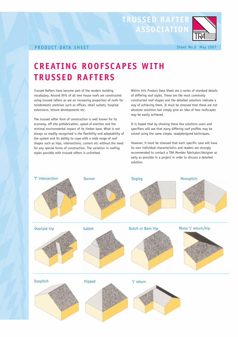
CREATING ROOFSCAPES WITH
TRUSSED RAFTERS
Trussed Rafters have become part of the modern building
vocabulary. Around 95% of all new house roofs are constructed
using trussed rafters as are an increasing proportion of roofs for
nondomestic premises such as offices, retail outlets, hospital
extensions, leisure developments etc.
The trussed rafter form of construction is well known for its
economy, off site prefabrication, speed of erection and the
minimal environmental impact of its timber base. What is not
always so readily recognised is the flexibility and adaptability of
the system and its ability to cope with a wide range of roof
shapes such as hips, intersections, corners etc without the need
for any special forms of construction. The variation in roofing
styles possible with trussed rafters is unlimited.
Within this Product Data Sheet are a series of standard details
of differing roof styles. These are the most commonly
constructed roof shapes and the detailed solutions indicate a
way of achieving them. It must be stressed that these are not
absolute solutions but simply give an idea of how roofscapes
may be easily achieved.
It is hoped that by showing these few solutions users and
specifiers will see that many differing roof profiles may be
solved using the same simple, readydesigned techniques.
However, it must be stressed that each specific case will have
its own individual characteristics and readers are strongly
recommended to contact a TRA Member fabricator/designer as
early as possible in a project in order to discuss a detailed
solution.
Sheet No.6 May 2007P R O D U C T DATA S H E E T
Duopitch Hipped ‘L’ return
‘T’ intersection Dormer Dogleg Monopitch
Overlaid hip Gablet Dutch or Barn hip Mono ‘L’ return/hip
PA G E 2
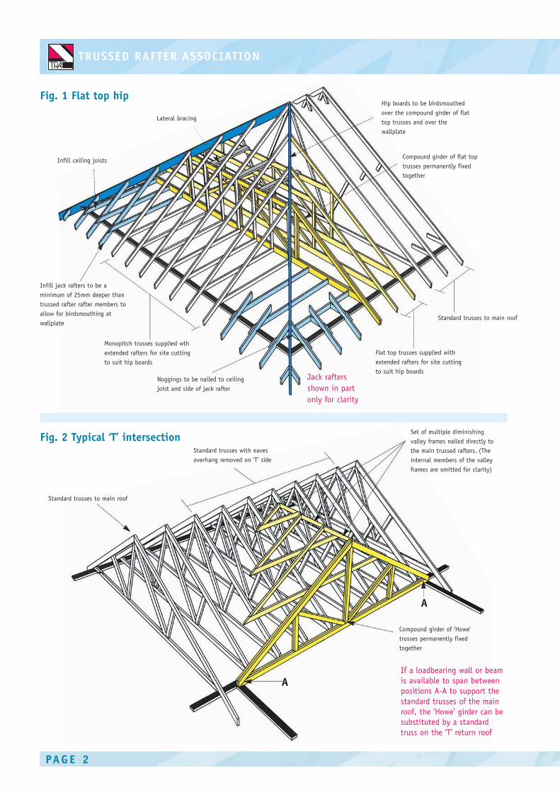
Fig. 1 Flat top hip
Fig. 2 Typical ‘T’ intersection
Hip boards to be birdsmouthed
over the compound girder of flat
top trusses and over the
wallplate
Compound girder of flat top
trusses permanently fixed
together
Standard trusses to main roof
Flat top trusses supplied with
extended rafters for site cutting
to suit hip boardsNoggings to be nailed to ceiling
joist and side of jack rafter
Monopitch trusses supplied wth
extended rafters for site cutting
to suit hip boards
Infill jack rafters to be a
minimum of 25mm deeper than
trussed rafter rafter members to
allow for birdsmouthing at
wallplate
Infill ceiling joists
Lateral bracing
Jack rafters
shown in part
only for clarity
Set of multiple diminishing
valley frames nailed directly to
the main trussed rafters. (The
internal members of the valley
frames are omitted for clarity)
Compound girder of ‘Howe’
trusses permanently fixed
together
Standard trusses with eaves
overhang removed on ‘T’ side
Standard trusses to main roof
If a loadbearing wall or beam
is available to span between
positions A-A to support the
standard trusses of the main
roof, the ‘Howe’ girder can be
substituted by a standard
truss on the ‘T’ return roof
A
A

Fig. 3 Typical ‘L’ return
PA G E 3
Fig. 4 Overlaid hip
Ridgeboard
Set of multiple mono valley
frames (smallest omitted for
clarity)
Compound girder of multiple
trusses permanently fixed
together
Compound girder of flat top
trusses permanently fixed
together
Lateral bracing
Standard trusses with eaves
overhang removed on hip side
Set of multiple valley
framesincluding two special flat
top frames to spread imposed load
Standard trussed rafters
Standard trusses to main roof
Compound girder of flat top
trusses permanently fixed
together
Hip boards to be birdsmouthed
over compound girder of flat
top trusses and over wallplate
PA G E 4
T R U S S E D R A F T E R A S S O C I AT I O NP.O.Box 571
Chesterfield S40 9DH
Tel & Fax: 01246 230036
email:[email protected]
www.tra.org.uk
This product Data Sheet has been produced to give some ideas on how trussed rafter construction may be adapted in order to provide a
range of roof intersections within the overall roof structure. However, it must be stressed that these are typical solutions and each roof
will have its own individual characteristics, readers are strongly recommended to contact a TRA Member fabricator/designer as early as
possible in a project in order to discuss a detailed solution.
More details on trussed rafter construction are contained within the TRA ‘Technical Hanbook’ which is a priced publication available from
the Trussed Rafter Association at the address given below.
The guidelines within this Data Sheet are issued in good faith but without liability and its use is entirely at the user’s risk.
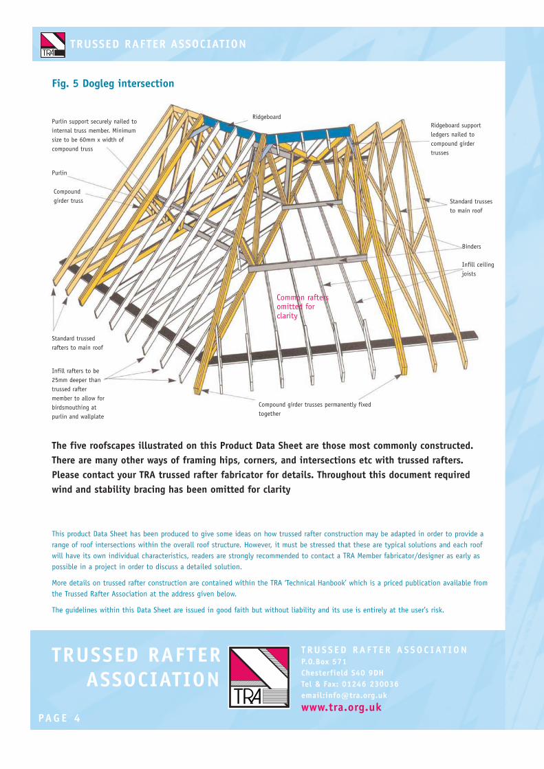
Fig. 5 Dogleg intersection
Ridgeboard
Ridgeboard support
ledgers nailed to
compound girder
trusses
Standard trusses
to main roof
Binders
Infill ceiling
joists
Compound girder trusses permanently fixed
together
Infill rafters to be
25mm deeper than
trussed rafter
member to allow for
birdsmouthing at
purlin and wallplate
Standard trussed
rafters to main roof
Compound
girder truss
Purlin
Purlin support securely nailed to
internal truss member. Minimum
size to be 60mm x width of
compound truss
The five roofscapes illustrated on this Product Data Sheet are those most commonly constructed.
There are many other ways of framing hips, corners, and intersections etc with trussed rafters.
Please contact your TRA trussed rafter fabricator for details. Throughout this document required
wind and stability bracing has been omitted for clarity
Common raftersomitted forclarity

CHIMNEY AND HATCH OPENINGS IN
TRUSSED RAFTER ROOFS
Sheet No.7 May 2007P R O D U C T DATA S H E E T
Unless subject to special design, hatches and chimneys
should be accommodated within the standard spacing
between trussed rafters.
It cannot be overstressed that the strength and lightness of
trussed rafters derives from the combination of members
and joints brought together in a triangulated framework.
Unless subject to special design arrangements with the
trussed rafter designer, truss members must never be cut or
trimmed.
In order to accommodate normally occuring features in a
dwelling, however, this Product Data Sheet shows ways of
re-positioning trussed rafters so that chimneys, hatches etc
can be incorporated into the roof without the need for
cutting.
Figures 1 and 2 show the principles of trimming around
chimneys by closing up the spacing of adjacent trussed
rafters to ensure that no individual trussed rafter carries
significantly more load than it would have done had it been
spaced normally. The opening for the chimney must
obviously then include additional loose timbers in order to
provide support for tiling battens and ceilings.
Figures 3 and 4 show the suggested layout of trusses for
openings up to 2 x standard truss spacing (normally 600
mm) and up to 3 x normal spacing respectively.
For clarity roof bracing has been omitted
from sketches in this Data Sheet. Bracing
should be installed and be continuous
even in areas of site installed infill.
Purlins supported each end on
at least 2 trusses
Site installed
infill
Purlin
TrimmerTrimmer
TrimmerTrimmer
Purlin supported each
end by two trusses and
by prop fixed to web of
truss
Collar supporting
ridgeboard
Binder
Fig. 1 Framing around chimney
Fig. 2 Cross-section
through chimney
Depending upon type of chimney flue
adequate gap should be left between
trimmers and chimney
S
B
B
S
A

This Product Data Sheet is intended to give some ideas on how to frame around openings in trussed rafter roofs. It must be stressed
that these are typical solutions to framing openings since each roof will have its own characteristics. Readers are strongly
recommended to contact their truss supplier/designer as early as possible in the contract in order to ascertain whether these details
are relevant to their particular set of circumstances.
Under NO circumstances should trussed rafter members ever be cut or trimmed unless this has been specifically approved by the
trussed rafter designer. Further detailed reading on site installation methods can also be found in the ‘Technical Handbook ’ which is a
priced publication available from the Trussed Rafter Association.
T R U S S E D R A F T E R A S S O C I AT I O NP.O.Box 571
Chesterfield S40 9DH
Tel & Fax: 01246 230036
email:[email protected]
www.tra.org.uk
In the case of 2 x normal spacing purlins, binders and
ridgeboards should typically be at least 47 x 125mm (nom size),
trimmers should be min 47 x 100mm. For the 3 x normal
spacing solution purlins, ridgeboards and binders should
typically be increased to 47 x 175mm and trimmers to
47 x 125mm. In both cases loose rafters should be 25mm
deeper than the rafter members of trussed rafters in order to
facilitate birdsmouthing over purlins and binders.
NOTE: TRA recommends the use of kiln-dried, strength graded
timber of Strength Class C16 or better for site installed infill
members.
Figures 5 & 6 show the similar solution when trimming around
loft hatches at ceiling tie level.
Although the sketches and data contained in this Product Data
Sheet show primarily how to deal with standard ‘fink’ trussed
rafters the principles explained are equally relevant to roofs
constructed with other types of trussed rafter. Consult your
trussed rafter supplier for more details.
These details should not, however, be applied to raised tie or
extended joist trusses since their construction may prevent the
use of multi-ply trusses. Contact your trussed rafter supplier for
further information.
Special detail for low-pitched roofs
Figures 2 and 6 show the normal method of supporting purlins
at supporting trussed rafters when allowing for openings in the
roof. This method involves placing the purlins parallel to the
internal web members of the trussed rafter supported by a prop
nailed to the web member.
This works well except in cases of low-pitched roofs where the
purlin can approach the horizontal position. In these cases it is
necessary to construct a support framework for the purlin,
nailed to the side of the truss as shown in Fig. 7
Loose infill Purlins supportedeach end on at least2 trusses
Collar supportingridgeboard
Purlin Purlin
Binder
Trimmers
Purlin end supported bysite constructedframework or usingproprietary steel hanger
Ask trussed rafter supplier for nailing details
Fig. 5 Framing around hatch
Fig. 6 Cross section through hatch
Fig. 7 Supporting purlins in low-pitched roofs
S
B
B
S
A

LOFT CONVERSIONS WITH TRUSSED
RAFTER ROOFS
Sheet No.8 May 2007P R O D U C T DATA S H E E T
There is a quiet revolution going on in the housebuilding
industry which impacts on many householders. Until a few
years ago most house roofs were constructed with simple
trussed rafters; lightweight yet robust frameworks
constructed from specially selected timber joined with
patented connector plates.
In recent years financial pressure and shortage of land has
encouraged builders to review their building habits and
nowhere more so than in the roofspace. Around one third of
all new house roofs are constructed using specially designed
‘Room in the Roof’ or ‘Attic’ trussed rafters which are
constructed using the same tried and tested techniques as
in the past but now intrinsically include roof space
accommodation within the design.
Once the trusses are fixed in place you automatically have
roof level space for a couple of new bedrooms or a study, all
on the same plot size as before. All this and better looking
houses too – there can be no denying that the move
towards steeper pitched roofs and dormer windows has
improved the appearance of new homes.
Is it any wonder then that owners of existing houses aspire
to the same advantages of functionality and lifestyle – but
there can be pitfalls awaiting the unwary. Firstly, be aware
that if your roof pitch is much less than 30° or your roof
span less than, say, 6 metres, then a worthwhile roof
conversion is likely to be impractical. The only possibility
may be to remove the roof completely and replace it with
modern ‘Room in the Roof’ trussed rafters.
If the size of your roof makes conversion to roof space
accommodation practical then, before you proceed any
further, please take some professional advice from a local
engineer or architect. If the home was built at any time
within the past 40 years then it will almost certainly have
trussed rafters as the structural skeleton of the roof.
Trussed rafters have many advantages for the builder being
strong and lightweight and deriving their overall strength
from the combination of external and internal members
joined by steel nailplates.
Hereby lies the problem. Trussed rafter members should
NEVER be removed or modified without first reinforcing the
roof by some other means (for example, the introduction of
purlins and binders to support the main members of the
truss). Larger joist members will have to be introduced to
support the new floor. This strengthening is not something
to be left to the untrained, it does need overseeing by a
qualified, professional designer. Not to do so could lead to
serious structural implications.
“Trussed rafter members should NEVER be removed or modified
in any way without first reinforcing the roof and this will need
overseeing by a qualified, professional engineer or architect”
Photo courtesy of the VELUX Company

This Product Data Sheet has been produced specifically to warn householders of the perils of modifying trussed rafter roofs in order to
provide roofspace accomodation without first seeking experienced professional advice.
The solution shown in Fig 1 is for illustrative purposes only and is not intended nor should it be taken to illustrate a specific solution
to any individual roof situation.
Further detailed reading on trussed rafter roof construction can also be found in the ‘Technical Handbook ’ which is a priced
publication available from the Trussed Rafter Association.
The guidelines contained within this Product Data Sheet are given in good faith but without liability and its use shall be entirely at
the risk of the user.
T R U S S E D R A F T E R A S S O C I AT I O NP.O.Box 571
Chesterfield S40 9DH
Tel & Fax: 01246 230036
email:[email protected]
www.tra.org.uk
In any event, the conversion of a roof comes under the control
of the Building Regulations, not just because of the structural
changes but, for example, thermal insulation and fire safety
are strictly controlled. In some cases the roof conversion may
affect other parts of your property such as the need for fire
doors off the staircase in order to ensure a safe means of
escape. Therefore, you are going to need help from a
professional.
Surely this investment in your property, which could reward
you both financially and from a lifestyle point of view,
deserves to be supervised by an expert – either a local
engineer or architect or by one of the specialist companies
who offer roof conversion. As with any company carrying out
work on your home, ask for references from them for other
similar, successful projects that they have completed.
Existing trussed rafter internal
members removed only after roof
strengthening is complete
New steel or timberbeam
Fig 1. A typical arrangement of new roof members
New stud wall built upoff new beam tosupport rafter
Possible new collar
Possible new rafter tostrengthen existing & alsoallow increased insulation
New steel or timberbeam
New floor joists inhangers supported bynew beams
New steel or timberbeam
Existing ceilingretained
The following sketch shows a typical but entirely
hypothetical solution to trussed rafter roof
conversion. Its intention is to emphasise the fact
that NO trussed rafter should ever be cut or
modified in any way until the new supporting
structure is in place.

HEALTH & SAFETY POLICY FOR THE
LOADING, HAULAGE, DELIVERY AND
ERECTION OF TRUSSED RAFTERS ON SITE
- A def in it ion of respons ib i l i t ies
Sheet No.9 May 2007P R O D U C T DATA S H E E T
Loading Trusses
The Truss Fabricator will either be responsible for in-house
haulage or for selecting a competent Haulier. In either case
he shall ensure that trailers suitably adapted for the safe
delivery of trussed rafters are used.
The Truss Fabricator will be responsible for providing the
Contractor with details of the weight, physical dimensions,
configuration and layout of the trusses to be delivered in
advance of delivery.
Details concerning weights of bundles of trusses and their
banding will be provided by the Truss Fabricator at time of
delivery.
NOTE 1 - For TRA members only a specimen risk assessment
for the loading of vehicles is available from the TRA
‘Members Only’ website (see H & S Notes 6)
Haulage of trusses
Where haulage is not to be provided in-house, the Truss
Fabricator is responsible for the appointment of a
competent Haulier. Competent in this context will mean a
Haulier that complies with all legislation and provides all
the drivers to be employed in delivering trusses with both
general and product related training.
The Truss Fabricator will ensure that every driver has
received suitable Health and Safety training before being
allowed to leave the truss fabrication yard.
NOTE 2 - For TRA Members use only see H & S Notes 7,
‘Check List for Hauliers of Trussed Rafters’ and ‘Driver
Induction Training including Driver Code of Practice’ both
available as downloads from the TRA Members only website.
Unloading, transport on site and storage of
trussed rafters
The Contractor is responsible for preparing a safe working
method for the unloading, transport on site and storage of
trussed rafters (See NOTE 4 over).
Should the safe working method identify any unusual
requirements the Contractor should notify the Truss
Fabricator before delivery.
The Contractor is responsible for the provision of
appropriate equipment and manpower to comply with this
safe working method and for the training of the manpower
and maintenance of the equipment.
The Contractor is responsible for providing suitable access
for the truss delivery lorry, level hard-standing for unloading
and the provisions for the safe separation of pedestrians
from the delivery and off-loading process.
Where a crane is used to off-load the Contractor is
responsible for providing a slinger/banksman suitably
trained in off-loading trusses. The hiring of the crane is the
Contractor’s responsibility.
If asked by the Contractor the Truss Fabricator and the
Haulier will, where appropriate, cooperate in the
development of a safe working method for these activities
NOTE 3 - If the contract is for the supply and erection the
Truss Fabricator may undertake responsibility for crane hire,
in which case he will also be responsible for providing
competent operators and for developing a safe working
practice.
Whilst on site the safety of the delivery driver shall be the
responsibility of the Contractor. However, the delivery driver
shall be empowered to refuse to off-load if any aspect of
the safe working method is contravened such that health
and safety is compromised.
(These Guidelines have been developed in association with the Health & Safety Executive
as a voluntary code of practice for the Trussed Rafter industry)

Trussed rafter manufacturers are advised to send a copy of this Product Data Sheet to their insurers or insurance brokers to
ensure that their activities are covered under the terms of existing insurance policies and to inform insurers, in writing, if they
undertake any activities which extend their responsibilities further.
HSE provide guidance on their website for delivering safely.
Visit: www.hse.gov.uk/workplacetransport/information/cooperation.htm for more information.
Further detailed reading on trussed rafter roof construction can also be found in the ‘Technical Handbook ’ published by TRA and
available from the address below.
T R U S S E D R A F T E R A S S O C I AT I O NP.O.Box 571
Chesterfield S40 9DH
Tel & Fax: 01246 230036
email:[email protected]
www.tra.org.uk
Construction of roofs
BUILDING DESIGN – THE CDM REGULATIONS
The Truss Fabricator is not the Building Designer. The
Building Designer, usually the Architect, is assumed by the
Truss Fabricator to be a competent person within the
meaning of Health and Safety legislation and, by specifying
timber trussed rafters for the roof structure, is deemed to
have taken responsibility for choosing a design solution
which satisfies CDM requirements.
Where such information would not be obvious to a
competent Building Designer, the Truss Fabricator will
convey to him clear information on, for example, truss
weights, dimensions, configurations and the layout and
erection sequence for trusses.
The Building Designer will be responsible for ensuring the
scheme of trusses proposed by the Truss Fabricator satisfies
the requirements of the CDM regulations.
Erecting trussed rafters
Unless the contract is for supply and erect, the Truss
Fabricator’s responsibility in the development of safe
working methods relating to truss erection shall be limited
to providing information and assistance in development of
the safe working plan.
However the Truss Fabricator does have a duty of care to
convey to the contractor any information which would not
be obvious to an experienced competent contractor. This
could include specific requirements for the erection
sequence of trusses or the specification of temporary
bracing required to ensure stability during erection.
NOTE 4 - TRA publish the ‘Technical Handbook’ which
includes general information relating to health & safety on
site as well as hints on correct storage and handling of
trussed rafters.