room temperature controller - automatizari-cladiri.ro · ce1n3331en 2017-12-05 building...
TRANSCRIPT

CE1N3331en2017-12-05
Building TechnologiesHVAC Products
3331
Synco™ 100
Room TemperatureController
RLA162
with 2 outputs DC 0…10 V
Room temperature controller for basic ventilation, air conditioning and heatingplants. Compact design with 2 analog control outputs DC 0…10 V for heatingand/or cooling.
Use
Plant types:· Small ventilation or air conditioning plants with own air handling section· Small heating plants· Heating section of larger ventilation or air conditioning plants· Ventilation zones of ventilation or air conditioning plants with central air handlingBuilding types:· Small residential buildings· Non-residential buildings of all types· Apartments with a suitable reference room· Individual rooms (e.g. conference rooms, training centers)· Devices that can be controlled:· Heating valve actuators· Cooling valve actuators· Air damper actuators· Current valves of electric air heater batteries

2/8
Building Technologies Room temperature controller RLA162 CE1N3331enHVAC Products 2017-12-05
Functions
· Control of the room temperature through modulating control of the actuating deviceon the water- or air-side with selectable operating action of the control signals forheating only or cooling only or heating and cooling
· Outside temperature compensation· Minimum limitation of the supply air temperature· Setpoint changeover via external contact· Test mode as a commissioning aid
Ordering
When ordering, please give the type reference RLA162
Equipment combinations
Actuators and controls must meet the following specification:· Control input: modulating, DC 0…10 V· Operating voltage: AC 24 VFor auxiliary functions, the following products can be used:
Type of unit Type ref. Data SheetAir duct temperature controller (as a minimum limiter) RLM162 N3332Outside sensor (for outside temperature compensation) QAC22 N1811
Technical design
· 1-stage heating· 1-stage cooling· 2-stage heating· 1-stage heating and 1-stage cooling
The following settings are required:· Room temperature setpoint: to be adjusted with the setting knob which can be ac-
cessed by the user· Operating action: the 2 control outputs Y1 and Y2 can act as follows:
- 1-stage heating: control output Y2 is not used- 1-stage cooling: control output Y2 is not used- 2-stage heating: both control outputs have the same operating action and operate
in sequence- 1-stage heating and 1-stage cooling: the control outputs have opposed operating
actions; the dead zone is fixed at 1.5 K· Control mode: P or PI; with PI mode, the integrated action time is fixed at 600 se-
conds· P-band: the P-band of control output Y1 is adjustable.
For Y2, the following applies:- With operating action Heating, the P-band of Y2 is identical to the P-band of Y1- With operating action Cooling, the P-band of Y2 is 50 % of the P-band of Y1
The RLA162 temperature controller compares the room temperature acquired by the sen-sor (integrated in the controller) with the setpoint. If there is a deviation, the controller gen-erates a DC 0…10 V control signal to adjust the regulating unit(s) between 0…100 %.
Main function
Other functions
Temperature control
Application ....
Settings
Control
3/8
Building Technologies Room temperature controller RLA162 CE1N3331enHVAC Products 2017-12-05
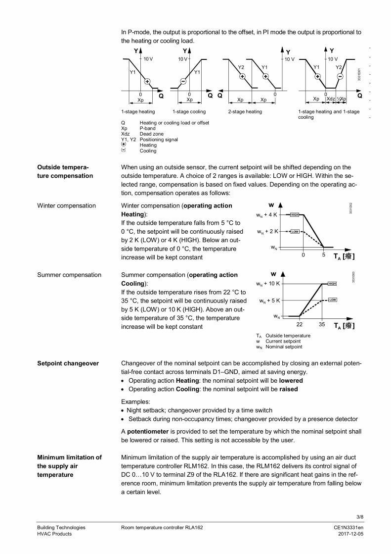
In P-mode, the output is proportional to the offset, in PI mode the output is proportional tothe heating or cooling load.
3331
D01
Y Y Y
Q Q Q
10 V 10 V 10 V
XpXp Xp XpXdzXp ½0 0
Y1Y2 Y2Y1Y1
Y
Q
10 V
Xp0
Y1
0
1-stage heating 1-stage cooling 2-stage heating 1-stage heating and 1-stagecooling
Q Heating or cooling load or offsetXp P-bandXdz Dead zoneY1, Y2 Positioning signal
HeatingCooling
When using an outside sensor, the current setpoint will be shifted depending on theoutside temperature. A choice of 2 ranges is available: LOW or HIGH. Within the se-lected range, compensation is based on fixed values. Depending on the operating ac-tion, compensation operates as follows:
Winter compensation Winter compensation (operating actionHeating):If the outside temperature falls from 5 °C to0 °C, the setpoint will be continuously raisedby 2 K (LOW) or 4 K (HIGH). Below an out-side temperature of 0 °C, the temperatureincrease will be kept constant
3331
D02w
TA [癈]wN
0 5
wN + 4 K
LOW
HIGH
wN + 2 K
Summer compensation Summer compensation (operating actionCooling):If the outside temperature rises from 22 °C to35 °C, the setpoint will be continuously raisedby 5 K (LOW) or 10 K (HIGH). Above an out-side temperature of 35 °C, the temperatureincrease will be kept constant
3331
D03w
wN
22 35
wN + 10 K
LOW
HIGH
wN + 5 K
TA [癈]TA Outside temperaturew Current setpointwN Nominal setpoint
Changeover of the nominal setpoint can be accomplished by closing an external poten-tial-free contact across terminals D1–GND, aimed at saving energy.· Operating action Heating: the nominal setpoint will be lowered· Operating action Cooling: the nominal setpoint will be raised
Examples:· Night setback; changeover provided by a time switch· Setback during non-occupancy times; changeover provided by a presence detector
A potentiometer is provided to set the temperature by which the nominal setpoint shallbe lowered or raised. This setting is not accessible by the user.
Minimum limitation of the supply air temperature is accomplished by using an air ducttemperature controller RLM162. In this case, the RLM162 delivers its control signal ofDC 0…10 V to terminal Z9 of the RLA162. If there are significant heat gains in the ref-erence room, minimum limitation prevents the supply air temperature from falling belowa certain level.
.
.
.
.
.
.
.
.
.
.
Outside tempera-ture compensation
Setpoint changeover
Minimum limitation ofthe supply airtemperature
4/8
Building Technologies Room temperature controller RLA162 CE1N3331enHVAC Products 2017-12-05
3331
D08
T [癈 ]
Y [V]
Z9
10 V
0 V
Yt
TL
3333
D04
T [癈 ]
Y [V]
Z9
10 V
0 V
10 Z9
Yt
TL
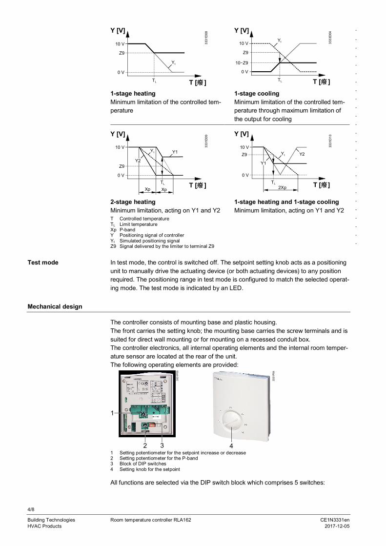
1-stage heatingMinimum limitation of the controlled tem-perature
1-stage coolingMinimum limitation of the controlled tem-perature through maximum limitation ofthe output for cooling
3331
D09
T [癈 ]
Y [V]
Z9
10 V
0 VTL
Y1Yt
Xp Xp
Y2
3331
D10
T [癈]
Y [V]
10 V
0 VTL
Y1
Yt Y2Z9
2Xp
2-stage heatingMinimum limitation, acting on Y1 and Y2
1-stage heating and 1-stage coolingMinimum limitation, acting on Y1 and Y2
T Controlled temperatureTL Limit temperatureXp P-bandY Positioning signal of controllerYt Simulated positioning signalZ9 Signal delivered by the limiter to terminal Z9
In test mode, the control is switched off. The setpoint setting knob acts as a positioningunit to manually drive the actuating device (or both actuating devices) to any positionrequired. The positioning range in test mode is configured to match the selected operat-ing mode. The test mode is indicated by an LED.
Mechanical design
The controller consists of mounting base and plastic housing.The front carries the setting knob; the mounting base carries the screw terminals and issuited for direct wall mounting or for mounting on a recessed conduit box.The controller electronics, all internal operating elements and the internal room temper-ature sensor are located at the rear of the unit.The following operating elements are provided:
3
1
2
3331
P03
3331
P04
41 Setting potentiometer for the setpoint increase or decrease2 Setting potentiometer for the P-band3 Block of DIP switches4 Setting knob for the setpoint
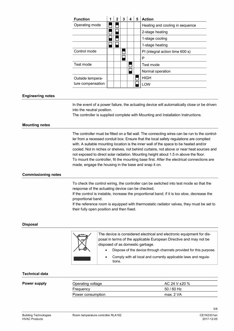
All functions are selected via the DIP switch block which comprises 5 switches:
.
.
.
.
.
.
.
.
.
.
.
.
.
.
.
.
.
.
.
.
.
.
.
.
.
.
.
Test mode
5/8
Building Technologies Room temperature controller RLA162 CE1N3331enHVAC Products 2017-12-05
Function 1 2 3 4 5 ActionOperating mode Heating and cooling in sequence
2-stage heating
1-stage cooling
1-stage heatingControl mode PI (integral action time 600 s)
PTest mode Test mode
Normal operation
Outside tempera-ture compensation
HIGH
LOW
Engineering notes
In the event of a power failure, the actuating device will automatically close or be driveninto the neutral position.The controller is supplied complete with Mounting and Installation Instructions.
Mounting notes
The controller must be fitted on a flat wall. The connecting wires can be run to the control-ler from a recessed conduit box. Ensure that the local safety regulations are compliedwith. A suitable mounting location is the inner wall of the space to be heated and/orcooled. Not in niches or shelves, not behind curtains, not above or near heat sources andnot exposed to direct solar radiation. Mounting height about 1.5 m above the floor.To mount the controller, fit the mounting base first. After the electrical connections aremade, engage the housing in the base and snap it on.
Commissioning notes
To check the control wiring, the controller can be switched into test mode so that theresponse of the actuating device can be checked.If the control is instable, increase the proportional band; if it is too slow, decrease theproportional band.If the reference room is equipped with thermostatic radiator valves, they must be set totheir fully open position and then fixed.
Disposal
Technical data
Operating voltage AC 24 V ±20 %Frequency 50 / 60 HzPower consumption max. 2 VA
The device is considered electrical and electronic equipment for dis-posal in terms of the applicable European Directive and may not bedisposed of as domestic garbage.
· Dispose of the device through channels provided for this purpose.
· Comply with all local and currently applicable laws and regula-tions.
Power supply

6/8
Building Technologies Room temperature controller RLA162 CE1N3331enHVAC Products 2017-12-05
Setting range nominal setpoint 8…30 °CSetting range setpoint changeover 0…10 KP-band 1…50 KIntegral action time with PI control 600 sDead zone with heating and cooling in sequence 1.5 KControl outputs Y1, Y2
VoltageCurrent
DC 0…10 V, continuousmax. 1 mA
Max. cable length copper cable 1.5 mm2
For signal input B9For switching input D1
80 m80 m
Contact sensing (input D1–M) DC 6…15 V, 3…6 mAOperation
Climatic conditionsTemperatureHumidity
to IEC 721-3-3, class 3K50…+50 °C<95 % r.h.
TransportClimatic conditionsTemperatureHumidity
to IEC 721-3-2, class 2K3-25…+70 °C<95 % r.h.
Mechanical conditions class 2M2
EU Conformity (CE)
RCM Conformity
CE1T3330xx *)
CE1T3330en_C1*)Product standardsAutomatic electrical controls for householdand similar use
EN 60 730-1 and EN 60 730-2-9
Electromagnetic compatibilityEmissionsImmunity
EN 50081-1EN 50082-1
Degree of protection IP 30 EN 60 529Safety class II to EN 60 730Degree of contamination normal
Connection terminals for solid wires or stranded wires 2 × 1.5 mm2 or 1 × 2.5 mm2
Weight 0.25 kg*) The documents can be downloaded from http://siemens.com/bt/download.
Connection terminals
B9 M
Y1 Y2 3331
G01
G
G0
Z9 D1 GND
B9 Outside sensorD1 Input for setpoint changeoverG Operating voltage AC 24 V, system potential SPG0 Operating voltage AC 24 V, system neutral SNGND GroundY1 Control output DC 0…10 VY2 Control output DC 0…10 VZ9 Limitation input DC 0…10 V
Functional data
Environmental condi-tions
Norms and standards
General
7/8
Building Technologies Room temperature controller RLA162 CE1N3331enHVAC Products 2017-12-05
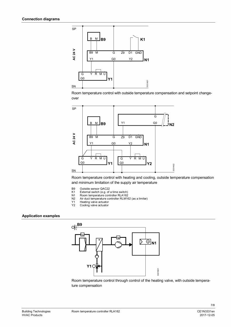
Connection diagrams
SP
B9 M D1 GND
Y1 Y2
RY
SN
Y1
N1
3331
A01
AC
24V
GG0
M U
G
G0
Z9
B9B M K1
Room temperature control with outside temperature compensation and setpoint change-over
SP
B9 M D1 GND
Y1 Y2
RY
SN
Y1
N1
3331
A02
AC
24V
GG0
M U
G
G0
Z9
B9B M N2
G
G0Y1
RY
Y2G
G0M U
Room temperature control with heating and cooling, outside temperature compensationand minimum limitation of the supply air temperatureB9 Outside sensor QAC22K1 External switch (e.g. of a time switch)N1 Room temperature controller RLA162N2 Air duct temperature controller RLM162 (as a limiter)Y1 Heating valve actuatorY2 Cooling valve actuator
Application examples
T
3331
S01
DpDp
N1
Y1
B9
Room temperature control through control of the heating valve, with outside tempera-ture compensation

8/8
Building Technologies Room temperature controller RLA162 CE1N3331enHVAC Products 2017-12-05
3331
S02
Dp
Y2
Dp
N1T
B9
Y1
N2T
Room temperature control through control of the heating and cooling valve, with outsidetemperature compensation and limitation of the supply air temperatureB9 Outside sensor QAC22N1 Room temperature controller RLA162N2 Air duct temperature controller RLM162Y1 Heating valveY2 Cooling valve
Dimensions
97
114
43
3331
M01
90
4
428 28
2828
26 30
3530
12
104
4
Dimensions in mm
Published by:Siemens Switzerland Ltd.Building Technologies DivisionInternational HeadquartersGubelstrasse 226301 ZugSwitzerlandTel. +41 58-724 24 24
www.siemens.com/buildingtechnologies
© Siemens Switzerland Ltd . 2017
Delivery and technical specifications subject to change