room unit for boiler control with opentherm … · room unit for boiler control with opentherm...
TRANSCRIPT

Edition 1.2Device series ACE1P2284en10.07.2002
Siemens Building TechnologiesHVAC Products
QAA73.110Room Unit for Boiler Control with OpenThermInterfaceBasic Documentation

2/70
Siemens Building Technologies Basic Documentation QAA73.110 Room unit CE1P2284enHVAC Products 10.07.2002

3/70
Siemens Building Technologies Basic Documentation QAA73.110 Room unit CE1P2284enHVAC Products Contents 10.07.2002
Contents
1 Summary.........................................................................................................6
1.1 Features...........................................................................................................61.2 Range of products ...........................................................................................71.3 Field of use ......................................................................................................71.4 Product liability.................................................................................................71.5 Environmental compatibility .............................................................................7
2 Handling..........................................................................................................8
2.1 Engineering......................................................................................................82.2 Installation........................................................................................................82.3 Electrical installation ......................................................................................112.4 Operation .......................................................................................................122.5 Communication with boiler control .................................................................142.6 Parameter settings for the enduser................................................................142.6.1 Overview of enduser parameters...................................................................152.7 Parameter settings for the heating engineer..................................................162.7.1 Overview of heating engineer parameters .....................................................172.8 Parameter settings for the OEM ....................................................................192.8.1 Overview of OEM parameters........................................................................202.9 Commissioning ..............................................................................................202.10 Operational faults...........................................................................................21
3 Description of enduser settings .................................................................22
User interface.................................................................................................223.1 Heating circuit operating modes ....................................................................223.2 Operating mode of d.h.w. heating..................................................................223.3 Occupancy button..........................................................................................233.4 Info button......................................................................................................23
Time of day ....................................................................................................243.5 Time of day, date and year ............................................................................24
Setpoints ........................................................................................................253.6 Nominal room temperature setpoint...............................................................253.7 Reduced room temperature setpoint .............................................................263.8 Frost protection setpoint of room temperature (TRF) ....................................263.9 Nominal d.h.w. temperature setpoint .............................................................27
Time switch programs TSP1 and TSP2 and d.h.w. .......................................283.10 Preselecting the weekday..............................................................................283.11 Switching times..............................................................................................29
Holidays .........................................................................................................303.12 Holiday setting ...............................................................................................303.13 Heating circuit operating level during holidays ..............................................30
General ..........................................................................................................313.14 Standard times...............................................................................................313.15 Summer / winter changeover temperature.....................................................323.16 Language.......................................................................................................333.17 Indication of faults ..........................................................................................333.18 Boiler status code ..........................................................................................34
4 Description of the heating engineer settings............................................35
Service values ...............................................................................................35

4/70
Siemens Building Technologies Basic Documentation QAA73.110 Room unit CE1P2284deHVAC Products Contents 10.07.2002
4.1 Current room temperature setpoints ............................................................. 354.2 Attenuated outside temperature .................................................................... 354.3 Composite outside temperature .................................................................... 364.4 Actual value 2 of d.h.w. temperature............................................................. 374.5 D.h.w. flow rate ............................................................................................. 374.6 Actual boiler return temperature.................................................................... 374.7 Actual value of the flue gas temperature....................................................... 374.8 Actual value of solar collector temperature ................................................... 374.9 Actual value of solar storage tank temperature............................................. 384.10 OpenTherm mode ......................................................................................... 384.11 Current flow temperature setpoint HC1 and HC2.......................................... 38
Space heating ............................................................................................... 394.12 Heating curve slope ...................................................................................... 394.13 Minimum and maximum limitation of flow temperature HC1 and HC2.......... 404.14 Parallel displacement of heating curve HC1/HC2 ......................................... 414.15 Type of building construction ........................................................................ 424.16 Room influence ............................................................................................. 424.17 Switching differential of the room temperature.............................................. 434.18 Adaption of the heating curve ....................................................................... 444.19 Maximum forward shift for optimum start control .......................................... 464.20 Maximum forward shift for optimum stop control........................................... 46
D.h.w. ............................................................................................................ 474.21 Reduced setpoint of the d.h.w. temperature ................................................. 474.22 Release of d.h.w. heating.............................................................................. 474.23 Legionella function ........................................................................................ 484.24 D.h.w. operating mode selector .................................................................... 494.25 Control of d.h.w. circulating pump................................................................. 49
General.......................................................................................................... 494.26 Programming................................................................................................. 494.27 Clock time master.......................................................................................... 514.28 Winter- / summertime changeover ................................................................ 514.29 Summer- / wintertime changeover ................................................................ 52
5 Description of the OEM settings................................................................ 53
Space heating OEM ...................................................................................... 535.1 Maximum setpoint (TRwMax) and minimum setpoint (TRwMin) of room
temperature ................................................................................................... 535.2 Gain factor of room influence (KORR) .......................................................... 535.3 Constant for quick setback (KON)................................................................. 545.4 Boost of the room temperature setpoint (DTRSA) ........................................ 555.5 Limitation of rate of increase of flow temperature setpoint............................ 565.6 Measured value correction of room temperature .......................................... 56
D.h.w. OEM................................................................................................... 565.7 Maximum d.h.w. setpoint (TBWmax) ............................................................ 565.8 Setpoint of the legionella function ................................................................. 575.9 Dwelling time at legionella function setpoint ................................................. 575.10 Effect of legionella function on the circulating pump ..................................... 57
Service functions OEM.................................................................................. 585.11 Info display .................................................................................................... 585.12 Frost warning................................................................................................. 585.13 Operation....................................................................................................... 595.14 Action occupancy button ............................................................................... 595.15 Software version ........................................................................................... 59

5/70
Siemens Building Technologies Basic Documentation QAA73.110 Room unit CE1P2284enHVAC Products Contents 10.07.2002
6 Functions......................................................................................................60
6.1 Types of compensation..................................................................................606.1.1 Weather compensation..................................................................................606.1.2 Weather compensation with room influence..................................................606.1.3 Room compensation......................................................................................616.2 Automatic 24-hour heating limit .....................................................................616.2.1 Without room influence ..................................................................................616.2.2 With room influence .......................................................................................626.3 Quick setback with room influence ................................................................636.4 D.h.w. push....................................................................................................636.5 Frost protection..............................................................................................646.5.1 Frost protection for the building .....................................................................646.5.2 Frost protection for the boiler and the d.h.w. .................................................64
7 Dimensions...................................................................................................65
8 Technical data ..............................................................................................66

6/70
Siemens Building Technologies Basic Documentation QAA73.110 Room unit CE1P2284enHVAC Products Summary 10.07.2002
1 SummaryThe QAA73.110 is a digital multi-functional room unit for one or 2 heating circuits andd.h.w. control.
Boiler control delivers the outside temperature and other information to the QAA73.110room unit via the OpenTherm communication interface. Based on the outsidetemperature, the room temperature and a number of other parameters, the interfacecalculates the required flow temperature setpoints for one or 2 heating circuits andtransmits them to the boiler control. In addition, the d.h.w. temperature setpoint istransmitted to the boiler control.
The optimization functions offer energy savings without sacrificing comfort. The roomsensor required for that purpose is integrated in the unit.
1.1 Features
• Operating sections (operating levels) based on ergonomic and functionalconsiderations
• Clear assignment of basic functions:− Operating mode, setpoint adjustment and occupancy button− A number of actual values can be accessed via the Info button− Additional functions can be programmed after opening the cover− Special service level with protected access
• Every setting or change is displayed and thus acknowledged• Yearly clock with automatic summer- / wintertime changeover• One heating program per heating circuit with up to 3 heating periods per day can be
selected on an individual basis• D.h.w. program with up to 3 heating periods per day can be selected on an
individual basis• Holiday program• The heating programs and the d.h.w. program can be reset to their default settings• Programming lock (e.g. for child-proofing)• Clear text display in a number of selectable languages• Special mode for setting the parameters of Siemens boiler control systems
• Weather-compensated flow temperature control while giving consideration to thebuilding’s thermal dynamics
• Weather-compensated flow temperature control with room compensation• Pure room temperature control• Effect of room temperature deviation can be adjusted• Optimum start / stop control• ECO functions (24-hour limit switch, automatic summer / winter changeover)• Room temperature switching differential for limiting the room temperature• Adjustable maximum limitation of the flow temperature (especially in connection with
floor heating systems)• Limitation of the rate of increase of the flow temperature setpoint• Frost protection for the building, frost warning• D.h.w. control with release and preselection of setpoint for the boiler controller• Legionella function• Integrated yearly clock with a reserve of at least 12 hours
Brief description
Operating functions
Functions

7/70
Siemens Building Technologies Basic Documentation QAA73.110 Room unit CE1P2284enHVAC Products Summary 10.07.2002
• Elegant housing made of recyclable plastic• Communication with the boiler control via OpenTherm interface• Power supply via OpenTherm bus
1.2 Range of products
Boiler Management Unit Premix TOP LMU6xThird party boiler control with OpenTherm interfaceRoom unit withOpenTherm interface QAA73.110Mounting clips for panel mounting AVS92.299
1.3 Field of use
The room units are designed for the OEM market. They are supplied directly to theboiler manufacturer and enhance the functionality and the level of control of small gas-fired appliances with integrated boiler temperature controllers.
Suited for use in residential buildings with own heating systems, such as:• Single or 2-family houses• Smaller multifamily houses• Holiday houses and villas
Standard heating systems, such as radiator, convector, underfloor and ceiling heatingsystems, and radiant panels. Especially suited for heating plants with pump heatingcircuits. If the boiler control systems feature integrated mixing valve control, it is alsopossible to control mixing heating circuits.
Primarily in connection with:• Heating boilers or small gas-fired appliances or condensing boilers• Heating boilers or instantaneous water heaters with integrated d.h.w. storage tank
that can be controlled with an appropriate OpenTherm signal
1.4 Product liability
• The products may only be used in building services plant and applications asdescribed above
• When using the products, all requirements specified under ”Technical data” must beobserved
• The local regulations for electrical installation must be complied with
1.5 Environmental compatibility
The unit contains electrical and electronic components and may not be disposed of ashousehold garbage. Local and currently valid legislation must be complied with!
Other features
Target market
Types of buildings
Types of heatingsystems
Heat generatingequipment
Note on disposal

8/70
Siemens Building Technologies Basic Documentation QAA73.110 Room unit CE1P2284enHVAC Products Handling 10.07.2002
2 Handling2.1 Engineering
• In the main living room or reference room• The place of installation should be chosen so that the sensor can capture the room
temperature as accurately as possible, without being affected by direct solarradiation or other heating or cooling sources.
• Mounting height is about 1.5 meters above the floor• The unit can be fitted to most commercially available recessed conduit boxes or
directly on the wall.
2.2 Installation
• Wall• Boiler control panel (with the help of clips)• The controller may not be exposed to dripping water• Permissible ambient temperature: 0...50 °C
Open the unit at the top and remove thebase from the housing front.
2284
Z36a
Fit the base to the wall with the help ofscrews.
2284
Z33a
Mounting location
Mounting conditions
Wall mounting1. step
2. step

9/70
Siemens Building Technologies Basic Documentation QAA73.110 Room unit CE1P2284enHVAC Products Handling 10.07.2002
Pull the bus cable through the opening ofthe base and connect it to the screwteminals.
2284
Z34a
Engage the housing front at the top ofthe base and close the unit to thebottom.
2284
Z35a
Pull the bus cable through the openingof the base and connect it to the screwteminals.
2284
Z37
Engage the housing front at the top ofthe base and close the unit to thebottom.
2284
Z35a
3. step
4. step
Mounting in a panelcut-out1. step
2. step

10/70
Siemens Building Technologies Basic Documentation QAA73.110 Room unit CE1P2284enHVAC Products Handling 10.07.2002
Slide the unit into the panel cut-outwithout applying any force Note:Do not use any tools when inserting theunit into the cut-out. If it does not fit,check the size of the cut-out and thehousing.
2284
Z15
Fit the clips (usually 4 pieces) to the rearof the housing. They engage on thehousing.
2284
Z38
The controller’s mounting dimensions are 92 x 92 mm.Due to the dimensions of the front, however, the standard spacing is 96 mm.The mechanical mounting facility allows the controller to be fitted in front panels havinga thickness of 1 to 3 mm.
96
1...2.5
92+0
.8-0
92 +0.8-0
2284
M01
96
3. step
4. step
Dimensions of cut-out

11/70
Siemens Building Technologies Basic Documentation QAA73.110 Room unit CE1P2284enHVAC Products Handling 10.07.2002
2.3 Electrical installation
The local regulations for electrical installations must be complied with.
1
34
56 2
2284
Z40
123456
COACOB----
OpenTherm terminal A (interchangeable)OpenTherm terminal B (interchangeable)----
23 mA max
Regulations forinstallation
Connection diagram

12/70
Siemens Building Technologies Basic Documentation QAA73.110 Room unit CE1P2284enHVAC Products Handling 10.07.2002
2.4 Operation
1
2
3
4
2284
Z01
7
8
56
1. First operating level 2. Second operating level
Operating element Function
Occupancy button Changeover of operating level
Setpoint knob for nominal temperature Adjustment of room temperaturesetpoint
Info button Change of info display
LCD with 2 lines each with 16characters and pointer for operatingmode
Display of data and operating mode
Heating circuit operating mode buttonand associated symbols
Operating mode changes to:Automatic operationcontinuous operationStandby
D.h.w. operating mode button withassociated symbol
D.h.w. heating ON / OFF
Line selection buttons (up and down) Selection of operating line
Setting buttons (plus and minus) Setting the parameters
Operating elements 1 to 4.
Operating elements 5 to 8. Can be accessed only after opening a cover.
The room unit has 2 display levels:• The info level• The parameter setting / programming level
Operating elements
Legend
1. First operating level
2. First operating level
Display

13/70
Siemens Building Technologies Basic Documentation QAA73.110 Room unit CE1P2284enHVAC Products Handling 10.07.2002
Basic display:
1
2a 32b 2c
4
5
6
2284
z03
1 Actual value of room temperature2a Display of heating circuit operating
levelNominal
Reduced
Frost protection
2b Flame status (activated, if flamepresent)
2c Fault/service (activated, if faultpresent / service due)
3 Time pointer4 Time of day5 Heating circuit operating modes6 D.h.w. operating mode
Display of operating level, in this case ”Nominal”:
1
2284
z04 1 Current operating level
Display of measured value ”Outside temperature”:
1
2
2284
z05 1 Parameter name
2 Parameter value
Display of parameter ”Holidays start”:
1
2 3
2284
z06 1 Parameter name
2 Parameter number3 Parameter value
Examples of info level
Example of parameterlevel

14/70
Siemens Building Technologies Basic Documentation QAA73.110 Room unit CE1P2284enHVAC Products Handling 10.07.2002
2.5 Communication with boiler control
For communication between the QAA73.110 and boiler control, the OpenThermprotocol is used.OpenTherm differentiates between 2 modes, Plus and Lite:− In OpenTherm Plus mode, the QAA73.110 can read or write various standardized
objects via the bus− In OpenTherm Lite mode, the QAA73.110 delivers only one signal to the boiler
control for controlling the heat output. In the event of fault, boiler control signalsBoiler Lock-Out Fault to the QAA73.110
• The parameters displayed only in OpenTherm Plus mode are appropriatelyidentified in the parameter lists
• The following descriptions of the individual parameters refer to the use ofOpenTherm Plus and are based on the assumption that the relevant functions aresupported by boiler control. Only then is the full functionality of the QAA73.110ensured so that the most common applications can be fully covered
• If a parameter is not supported by boiler control, the display shows 3 strokes – – –in place of a value
2.6 Parameter settings for the enduser
The following settings can be made to meet the individual needs of the enduser.
Buttons Explanation Line1
PROG
Press one of the 2 line selection buttons.This will take you directly to the programming level"Enduser”.
1
2
PROG
Press the line selection buttons to select therequired line.The parameter list on the next pages contains allavailable lines.
1. . .50
3
- +
Press the + or – button to set the required value.The setting will be stored as soon as you leave theprogramming mode or change to another line.The parameter list on the next 2 pages contains allsettings that can be made.
4 By pressing the Info button, you leave theprogramming level "Enduser”.
Continuous
display
If no button is pressed for about 8 minutes, the room unit will automatically return to theInfo level.
OpenTherm bus
Notes
Description
Setting
Note

15/70
Siemens Building Technologies Basic Documentation QAA73.110 Room unit CE1P2284enHVAC Products Handling 10.07.2002
2.6.1 Overview of enduser parameters
Line Function Range Unit Resolution Factorysetting
Time of day1 Time of day 0 ... 23:59 hh:mm 1 min –2 Date (day, month) 1. Jan ... 31. Dec dd.mm 1 day –3 Year 2000 ... 2094 jjjj 1 year –Setpoints5 Reduced room temperature setpoint (TRRw) TRF ... TRN °C 0.5 16.06 Frost protection setpoint of room temperature
(TRF)4 ... TRRw °C 0.5 10.0
7* Nominal setpoint of the d.h.w. temperature(TBWw)
TBWR ... TBWmax °C 1 55
Time switch program 1 (heating circuit 1)10 Preselecting the weekday Mo...Su, week week-
day1 day –
11 Switch-on time period 1 – – : – – / 00:00 ... 24:00 hh:mm 10 min 06:0012 Switch-off time period 1 – – : – – / 00:00 ... 24:00 hh:mm 10 min 22:0013 Switch-on time period 2 – – : – – / 00:00 ... 24:00 hh:mm 10 min – – : – –
14 Switch-on time period 2 – – : – – / 00:00 ... 24:00 hh:mm 10 min – – : – –
15 Switch-on time period 3 – – : – – / 00:00 ... 24:00 hh:mm 10 min – – : – –
16 Switch-off time period 3 – – : – – / 00:00 ... 24:00 hh:mm 10 min – – : – –
Time switch program 220* Preselecting the weekday Mo...Su, week week-
day1 day –
21* Switch-on time period 1 – – : – – / 00:00 ... 24:00 hh:mm 10 min 06:0022* Switch-off time period 1 – – : – – / 00:00 ... 24:00 hh:mm 10 min 22:0023* Switch-on time period 2 – – : – – / 00:00 ... 24:00 hh:mm 10 min – – : – –
24* Switch-off time period 2 – – : – – / 00:00 ... 24:00 hh:mm 10 min – – : – –
25* Switch-on time period 3 – – : – – / 00:00 ... 24:00 hh:mm 10 min – – : – –
26* Switch-off time period 3 – – : – – / 00:00 ... 24:00 hh:mm 10 min – – : – –
Time switch program 3 (d.h.w.)30* Preselecting the weekday Mo...Su, week week-
day1 day –
31* Switch-on time period 1 – – : – – / 00:00 ... 24:00 hh:mm 10 min 06:0032* Switch-off time period 1 – – : – – / 00:00 ... 24:00 hh:mm 10 min 22:0033* Switch-on time period 2 – – : – – / 00:00 ... 24:00 hh:mm 10 min – – : – –
34* Switch-off time period 2 – – : – – / 00:00 ... 24:00 hh:mm 10 min – – : – –
35* Switch-on time period 3 – – : – – / 00:00 ... 24:00 hh:mm 10 min – – : – –
36* Switch-off time period 3 – – : – – / 00:00 ... 24:00 hh:mm 10 min – – : – –
Holidays40 Holidays start (day.month) – – Inactive 1. Jan ... 31. Dec dd.mm 1 day – – : – –
41 Holidays end (day.month) – –: Inactive 1. Jan ... 31. Dec dd.mm 1 day – – : – –
42 Heating circuit operating level during holidays Frost, reduced – – FrostGeneral45 STANDARD time switch programs for HC1 + 2
and d.h.w. (press both buttons -/+ for 3 s)No, yes – – No
46 Summer / winter changeover temperature 8 ... 30 °C 0.5 17.047 Language German, English – – German50* Display of fault (error code of QAA73.110 or
boiler control)0 ... 255 – 1 –
* These lines are only displayed in OpenTherm Plus mode. Also, the relevant functions must be supported by boiler control. – – : – – = Switching point inactive

16/70
Siemens Building Technologies Basic Documentation QAA73.110 Room unit CE1P2284enHVAC Products Handling 10.07.2002
2.7 Parameter settings for the heating engineer
Room unit configuration and parameter settings to be made by the heating engineer.
Buttons Explanation Line1
PROG
Press one of the 2 line selection buttons.This will take you first to the programming level"Enduser”.
1
2
PROG
Press both line selection buttons for at least 3seconds.
This will take you to the programming level "Heatingengineer”.
51
3
PROG
Press the line selection buttons to select the requiredline.The parameter list on the next pages contains allavailable lines.
51. . .98
4
- +
Press the + or – button to set the required value.The setting will be stored as soon as you leave theprogramming mode or change to another line.The parameter list on the next pages contains allsettings that can be made.
5 You leave the programming level "Heating engineer"by pressing the Info button.
Continuous
display
If no button is pressed for about 8 minutes, the room unit will automatically return to theInfo level.
Description
Setting
Note
17/70
Siemens Building Technologies Basic Documentation QAA73.110 Room unit CE1P2284enHVAC Products Handling 10.07.2002
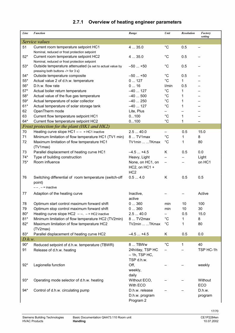
2.7.1 Overview of heating engineer parameters
Line Function Range Unit Resolution Factorysetting
Service values51 Current room temperature setpoint HC1
Nominal, reduced or frost protection setpoint4 ... 35.0 °C 0.5 –
52* Current room temperature setpoint HC2Nominal, reduced or frost protection setpoint
4 ... 35.0 °C 0.5 –
53* Outside temperature attenuated (is set to actual value bypressing both buttons -/+ for 3 s)
–50 ... +50 °C 0.5 –
54* Outside temperature composite –50 ... +50 °C 0.5 –55* Actual value 2 of d.h.w. temperature 0 ... 127 °C 1 –56* D.h.w. flow rate 0 ... 16 l/min 0.5 –57* Actual boiler return temperature –40 ... 127 °C 1 –58* Actual value of the flue gas temperature –40 ... 500 °C 1 –59* Actual temperature of solar collector –40 ... 250 °C 1 –61* Actual temperature of solar storage tank –40 ... 127 °C 1 –62 OpenTherm mode Lite, Plus – – –63 Current flow temperature setpoint HC1 0...100 °C 1 –64* Current flow temperature setpoint HC2 0...100 °C 1 –Frost protection for the plant (HK1 and HK2)70 Heating curve slope HC1 – – = HC1 inactive 2.5 ... 40.0 – 0.5 15.071 Minimum limitation of flow temperature HC1 (TV1 min) 8 ... TV1max °C 1 872 Maximum limitation of flow temperature HC1
(TV1max)TV1min ... ...TKmax °C 1 80
73 Parallel displacement of heating curve HC1 –4.5 ... +4.5 K 0.5 0.074* Type of building construction Heavy, Light – – Light75* Room influence None, on HC1, on
HC2, on HC1 +HC2
– – on HC1
76 Switching differential of room temperature (switch-offpoint)– – . – = inactive
0.5 ... 4.0 K 0.5 0.5
77 Adaption of the heating curve Inactive,active
– – Active
78 Optimum start control maximum forward shift 0 ... 360 min 10 10079 Optimum stop control maximum forward shift 0 ... 360 min 10 3080* Heating curve slope HC2 – –. – = HC2 inactive 2.5 ... 40.0 – 0.5 15.081* Minimum limitation of flow temperature HC2 (TV2min) 8 ... TV2max °C 1 882* Maximum limitation of flow temperature HC2
(TV2max)TV2min ... ...TKmax °C 1 80
83* Parallel displacement of heating curve HC2 –4.5 ... +4.5 K 0.5 0.0D.h.w.90* Reduced setpoint of d.h.w. temperature (TBWR) 8 ... TBWw °C 1 4091 Release of d.h.w. heating 24h/day, TSP HC
– 1h, TSP HC,TSP d.h.w.
– – TSP HC-1h
92* Legionella function Off,weekly,daily
– – weekly
93* Operating mode selector of d.h.w. heating Without ECO,With ECO
– – WithoutECO
94* Control of d.h.w. circulating pump D.h.w. releaseD.h.w. programProgram 2
– – D.h.w.program

18/70
Siemens Building Technologies Basic Documentation QAA73.110 Room unit CE1P2284enHVAC Products Handling 10.07.2002
Line Function Range Unit Resolution Factorysetting
General95 Programming lock Locked / released – – Released96* Clock time master QAA73, external – – QAA7397 Summer time start 1. Jan ... 31. Dec dd.mm 1 day 25. March98 Summer time end 1. Jan ... 31. Dec dd.mm 1 day 25. Oct
* These lines are only displayed in OpenTherm Plus mode. Also, the relevant functions must besupported by boiler control.

19/70
Siemens Building Technologies Basic Documentation QAA73.110 Room unit CE1P2284enHVAC Products Handling 10.07.2002
2.8 Parameter settings for the OEM
Boiler-specific settings and protective functions for the boiler manufacturer.
Buttons Explanation Line
1PROG
Press one of the 2 line selection buttons.This will take you first to the programming level"Enduser”.
1
2PROG
9 s
Press both line selection buttons for at least 9seconds.A special display for entering the code will appear.
3 CODE Press buttons - + and PROG to enter therequired combination of the access code.If the combination of buttons is correct, you reachthe programming mode ”OEM”.
Wrong code:If the code has been entered incorrectly, the displaywill change to the "Parameter settings for the heatingengineer”.
4PROG
Press the line selection buttons to select the requiredline.The parameter list on the next 2 pages contains allavailable lines.
100. . .199
5- +
Press the + or – button to set the required value.The setting will be stored as soon as you leave theprogramming mode or change to another line.The following parameter list contains all availablelines.
6 You leave the programming level "OEM" by pressingthe Info button.
Continuous
display
If no button is pressed for about 8 minutes, the room unit will automatically return to theInfo level.
Description
Setting
Note

20/70
Siemens Building Technologies Basic Documentation QAA73.110 Room unit CE1P2284enHVAC Products Handling 10.07.2002
2.8.1 Overview of OEM parameters
Line Function Range Unit Resolution Factorysetting
Space heating OEM100 Maximum room temperature setpoint (TrwMax) TRwMin ... 35 °C 0.5 35101 Minimum room temperature setpoint (TrwMin) 4 ... TRwMax °C 0.5 10102 Gain factor of room influence (KORR) 0 ... 20 – 1 4103 Quick setback constant (KON) (without room sensor) 0 ... 20 – 1 2104 Boost of room temperature setpoint (DTRSA), boost
heating0 ... 20 K 1 5
105 Limitation of rate of increase of flow temperaturesetpoint
0 ... 15 K/min 0.5 5
106 Measured value correction of room temperature –3.0 ... 3.0 °C 0.5 0D.h.w. OEM130* Maximum d.h.w. setpoint (TBWmax) TBWw 80 °C 1 60131* Setpoint of legionella function (d.h.w.) 8 ... 95 °C 1 65132* Dwelling time legionella function 0...360 min 10 0133* Effect of legionella function on circulating pump No / yes – – YesService functions OEM150 Info display Temporary,
continuously– – Temporary
151 Frost warning –. – = inactive –10 ... +10 °C 0.5 3.0152 Operation lock Locked,
released– – Released
153* Action occupancy button On HC1 + HC2,on HK1
– – On HC1+HC2
199 Software version (QAA73) 0 ... 99.9 – 1 –
* These lines are only displayed in OpenTherm Plus mode. Also, the relevant functions must besupported by boiler control.
2.9 Commissioning
Prior to commissioning the controller, make the following checks:• Correct mounting• Correct connection to OpenTherm bus• Enduser parameters are set as required• Heating engineer parameters are set in compliance with plant requirements• OEM parameters are set in compliance with technical requirements
The heating plant is started up via boiler control. To make the functional check, theindividual functions of the room unit are checked in the plant.
Prerequisites
Functional checks

21/70
Siemens Building Technologies Basic Documentation QAA73.110 Room unit CE1P2284enHVAC Products Handling 10.07.2002
2.10 Operational faults
No display on the room unit:• Is the heating plant's main switch turned on?• Are the fuses in order?• Check the wiringRoom unit displays a wrong time of day or a wrong date:• Set the right time of day, the right date and the year on the room unit if the
QAA73.110 is the clock master• Set the correct time of day and the date on the clock master (if present)
Boiler control does not switch on• Does boiler control really have to operate?• Press boiler control’s lock-out reset button• Check the control thermostat (TR) and the manual reset safety limit thermostat
(STB)• Check wiring and fuse of boiler control• Check the communication link to boiler control
The room temperature does not agree with the required temperature level:• Does the room temperature setpoint agree with the required temperature level?• Is the required operating mode indicated?• Are weekday, time of day and the displayed heating program correct?
(Info displays)• Has the heating curve slope been correctly set?• Check wiring of outside sensor• Has the ”Nominal room temperature setpoint” with the ”Parallel displacement of the
heating curve” been calibrated based on the effective room temperature?• Check boiler control
D.h.w. is not being heated:• Has the button for d.h.w. heating been pressed?• Check setpoint of the d.h.w. temperature• Check d.h.w. function of boiler control
Room unit
Boiler controller
Room temperature
D.h.w.

22/70
Siemens Building Technologies Basic Documentation QAA73.110 Room unit CE1P2284enHVAC Products Description of enduser settings 10.07.2002
3 Description of enduser settingsUser interface3.1 Heating circuit operating modes
The control provides 3 different heating circuit operating modes that can be directlyselected as required.
The operating modes are selected by pressing the heating circuit operating modebutton. It can be accessed after opening the cover.The selected heating circuit operating mode applies to both heating circuits and isindicated on the display by a pointer under the relevant symbol.
Operating
mode
Designation Effect of selected operating mode
Automaticoperation
• Heating circuit 1 according to time switch program 1• Heating circuit 2 according to time switch program 2• Holiday function is active
Continuousoperation
• Heating circuits 1 and 2 continuously according tothe adjusted nominal room temperature setpoint orreduced setpoint
• Holiday function is not active
Standby • Heating circuits 1 and 2 are switched off• Holiday function is not active• Frost protection functions are active
3.2 Operating mode of d.h.w. heating
D.h.w. heating can be switched on and off independent of the other operating modes.D.h.w. heating ON is indicated by a pointer under the d.h.w. symbol .
No pointer OFFComplete pointer ONHalf the pointer ON with ECO function
This operating mode must be enabled on setting line 93!
OFF D.h.w. is not being heated.
ON D.h.w. heating is switched on; a setpoint is generated based on thedemand for heat and the settings and passed on to the BMU.
ON ECO D.h.w. operating mode for plants with instantaneous d.h.w. heating.The setpoint is generated and passed on to the BMU. Die Temperaturwird jedoch durch die Kesselregelung nicht ständig auf dem Sollwertgehalten. D.h.w. heating is started only when d.h.w. is consumed.
• The d.h.w. operating mode and the different d.h.w. functions are active only ifsupported by boiler control and if communicated in OpenTherm Plus mode
• No d.h.w. functions are provided in OpenTherm Lite mode, that is, the d.h.w.operating mode button is inactive
Description
Operating modes, ,
Effect
Description
Effect
Notes

23/70
Siemens Building Technologies Basic Documentation QAA73.110 Room unit CE1P2284enHVAC Products Description of enduser settings 10.07.2002
The QAA73.110 has no frost protection function for d.h.w. heating. Frost protection ford.h.w. must be ensured by boiler control.
3.3 Occupancy button
In automatic and continuous operation, the heating circuit operation level can bechanged by pressing the occupancy button.
Current operating mode Effect on occupancy button
Automatic operation The heating circuit operation level changes temporarilyfrom nominal to reduced, or vice versa. This changeoveris maintained until the next level changeover point of thetime switch program is reached.The change taking place after pressing the occupancybutton will be indicated by the time pointer and appearson the display.The effect relates to HC1 + 2 or only to HC1, dependingon the selection of function 153.
Continuous operation The heating circuit operation level changes from nominalto reduced, or vice versa.
D.h.w. The occupancy button has no effect on d.h.w. heating.
Holiday program The occupancy button has no effect.summer operation After automatic summer changeover, the occupancy
button has no effect.
3.4 Info button
The Info level can be accessed any time by pressing the Info button. By repeatedlypressing the Info button, the various data made available by the Info level can bequeried.
Line Display
1 Time of day, actual room temperature and operating mode2 Indication of faults3 * Status display:4 Time of day and operating state heating circuit 15 Time of day and date6 * Actual value of outside temperature7 * Lowest outside temperature**8 * Highest outside temperature**9 Actual value of the room temperature10 Lowest room temperature**11 Highest room temperature**12 * Actual value of d.h.w. temperature13 * Actual value of the boiler temperature14 * Actual value of flow temperature15 * Burner modulation16 * Water pressure heating circuit
Depending on the configuration made (operating line 150), the information selected lastis continuously displayed, or changes back to the standard display after 8 minutes.
Caution
Description
Effect
Description

24/70
Siemens Building Technologies Basic Documentation QAA73.110 Room unit CE1P2284enHVAC Products Description of enduser settings 10.07.2002
* These lines are only displayed in OpenTherm Plus mode. Also, the relevantfunctions must be supported by boiler control.
** A reset to the actual temperature is made by pressing the +/– buttons for3 seconds
Time of day
3.5 Time of day, date and year
To ensure proper functioning of the heating program, the time switch with the time ofday, day, month and year must be correctly set.
1. Press the line selection buttons to select line 1, 2 or 3.2. Press the + / – buttons to set the current values.
Line Setting range Unit
123
00:00 ... 23:591. Jan ... 31. Dec2000 ... 2094
Minute, hour, day, month,year
Time of day, date and year will be set to their current values. These settings areimportant, ensuring that the heating program, the d.h.w. program, the holiday programand summer- / wintertime changeover of the room unit operate as required.
• While the settings are made, the clock continues to run• During the time settings, the seconds are reset to zero each time a + or – button is
pressed• If, on line 96, the clock master was programmed for external, manual time settings
via lines 1 to 3 are no longer possible
Description
Lines 1, 2 and 3
Effect
Notes

25/70
Siemens Building Technologies Basic Documentation QAA73.110 Room unit CE1P2284enHVAC Products Description of enduser settings 10.07.2002
Setpoints
3.6 Nominal room temperature setpoint
In nominal operation, the nominal room temperature setpoint is maintained.
The nominal room temperature setpoint is adjusted with the knob for the nominaltemperature, which is located on the controller front for direct access by the user.When turning the knob, the current room temperature setpoint is displayed and – whenturning further – readjusted. The value applies to both heating circuits.
Setting range Unit Factory setting
TRwMin ... TRwMax °C 20.0
0 2 4 6 8 10 12 14 16 18 20 22 24 35 °C
2284
Z07101 100
6
5
Room temperature setpoint setting ranges5 Reduced room temperature setpoint6 Frost protection setpoint of the room temperature
• Readjustment of the nominal setpoint with the knob can be locked via OEMparameter 152
• Minimum and maximum limitation of the nominal setpoint setting range can beaccomplished via OEM parameters 100 and 101
When the nominal room temperature setpoint is active, the rooms will be heatedaccording to the adjustment made with the setpoint knob.The adjustment made with the knob is only active in automatic and continuousoperation.
The nominal phases depend on the settings made on lines 11 through 16 for heatingcircuit 1 and according to the settings made on lines 21 through 26 for heating circuit 2.
0 2 4 6 8 10 12 14 16 18 20 22 24 h
Mo...So
2284
Z08
12 14 16
11 13 15
Nominal temperature and reduced temperature phases for heating circuit 1
Description
Nominal setpoint
Notes
Effect
Example

26/70
Siemens Building Technologies Basic Documentation QAA73.110 Room unit CE1P2284enHVAC Products Description of enduser settings 10.07.2002
3.7 Reduced room temperature setpoint
The reduced room temperature setpoint ensures a lower room temperature during thenight, for instance, to save energy.
1. Press the line selection buttons to select line 5.2. Press the + / – buttons to adjust the reduced room temperature setpoint.
Setting range Unit Factory setting
TRF...TRN °C 16
TRF Frost protection setpoint of room temperature (setting on line 6)
TRN Nominal room temperature setpoint (to be adjusted with the setpoint knob)
It is not possible to set the reduced setpoint above the adjustment made with thenominal temperature knob.
During the reduced phases, the reduced room temperature setpoint is maintained.Any lower nominal temperature is given priority however.
3.8 Frost protection setpoint of room temperature(TRF)
This function prevents the room temperature from falling below the adjusted frostprotection setpoint.
1. Press the line selection buttons to select line 6.2. Press the + / – buttons to adjust the frost protection setpoint of the room
temperature.
Setting range Unit Factory setting
4...TRRw °C 10
TRRw Reduced room temperature setpoint (setting on operating line 5)
This setting will change the frost protection setpoint of the room temperature.
This function is ensured only when the heating plant operates properly!
In operating mode , the room temperature is prevented from falling below a certainlevel. This means that the frost protection setpoint of the room temperature will bemaintained.
Description
Line 5
Note
Effect
Description
Line 6
Effect
Caution
Frost protection for thebuilding

27/70
Siemens Building Technologies Basic Documentation QAA73.110 Room unit CE1P2284enHVAC Products Description of enduser settings 10.07.2002
3.9 Nominal d.h.w. temperature setpoint
During nominal operation, the nominal d.h.w. setpoint is maintained. It is possible touse 2 different d.h.w. temperature setpoints.
1. Press the line selection buttons to select line 7.2. Press the + / – buttons to adjust the nominal setpoint of the d.h.w. temperature.
Setting range Unit Factory setting
TBWR...TBWmax °C 55
TBWR Reduced d.h.w. temperature setpoint (setting one line 90)TBWmax Maximum nominal setpoint of d.h.w. temperature (setting on line 130)
The temperature setpoint during normal d.h.w. operation will be changed.
0 10 20 30 40 50 60 70 80 90 100 120 130 140 °C
2284
Z17
90 7 130
7 Nominal d.h.w. temperature setpoint90 Reduced setpoint of the d.h.w. temperature130 Maximum nominal setpoint of d.h.w. temperature
D.h.w. heating has 2 different setpoints that can be used:
Nominal setpoint of d.h.w. temperature (setting on line 7): It ensures the d.h.w.temperature required during occupancy times.
Reduced d.h.w. temperature setpoint (setting on operating line 90): It ensures thed.h.w. temperature required during the main occupancy times.
The criteria required for releasing d.h.w. heating are defined by the settings made online 91.
Description
Line 7
Effect
D.h.w. temperaturesetpoints
D.h.w. charging

28/70
Siemens Building Technologies Basic Documentation QAA73.110 Room unit CE1P2284enHVAC Products Description of enduser settings 10.07.2002
Time switch programs TSP1 and TSP2 and d.h.w.For the 2 heating circuits 1 and 2 as well as for d.h.w., it is possible to defineindependent time switch programs. This serves the following purpose:• Space heating and d.h.w. heating operate only if there is a demand for heat• The user can set the occupancy times to suit his lifestyle• Energy can be saved by making adequate use of the time switch programsFor TSP1, parameters 10 through 16 are provided, für TSP2, the parameters 20through 26 and for TSP3 the parameters 30 through 36.• The time switch programs operate independently of each other.• Die Parameter 20 ... Parameters 20 through 26 are visible only if boiler control
supports a second heating circuit• Die Parameter 30 ... Parameters 30 through 36 are visible only if line 91 is set for
use by the d.h.w. time switch program
3.10 Preselecting the weekday
With this setting, you select the weekdays or the 7-day block for which the switchingtimes of the time switch program apply.
1. Press the line selection buttons to select line 10 or 20 or 30.2. Press the + / – buttons to preselect the 7-day block or the individual day.
Setting range Unit
Week Mo...Su 7-day blockIndividual days
• This setting must be made before the switching times are entered!• For every day on which other switching times shall apply, the preselection of the
individual day with subsequent entry of the switching times must be repeated
This setting is used to select either the whole week or individual days.
7-day block:Entry of the switching times on lines 11 through 16 (for HC1), or of lines 21 through 26(for HC2), or of lines 31 through 36 (for HC3), is identical for every day from Mondaythrough Sunday
Example of a time switch program valid for all weekdays
0 2 4 6 8 10 12 14 16 18 20 22 24 h
Mo...So
2284
Z18
11
12
Description
Notes
Description
Zeilen 10, 20, 30
Important
Effect
Entry of 7-day block

29/70
Siemens Building Technologies Basic Documentation QAA73.110 Room unit CE1P2284enHVAC Products Description of enduser settings 10.07.2002
7-day block: Entry of the switching times on lines 11 through 16 (for HC1), or of lines21 through 26 (for HC2), or of lines 31 through 36 (for d.h.w.), are only entered for theindividual day selected here
Example of a 7-day time switch program:
0 2 4 6 8 10 12 14 16 18 20 22 24 h
Sa
Mo
Di
Mi
Do
Fr
So
2284
Z19
First, choose the 7-day block to enter the switching times required for the majority ofdays; then, select the individual days to make the required adjustments.
3.11 Switching times
This setting defines the switching times for space heating and d.h.w. heating. Thetemperature setpoints of the 2 heating circuits and the d.h.w. usage times change atthe times set.
1. Press the line selection buttons to select lines 11 through 16 (for HC1), or lines 21through 26 (for HC2), or lines 31 through 36 (for d.h.w.).
2. Press the + / – buttons to set the switching time on each line.
Setting range Unit Factory setting
– – : – – / 24:00 h : min see standard time switch programs
First, select the weekday for which the switching times shall be entered! (operating line10 or 20 or 30)
The room unit then makes a check to ensure the entries have been made in the correctorder.
At the times entered, the program will switch to the respective functions:– – : – – Switching point inaktiv
00:00...24:00 At the time entered, a change to the respective function takes place.
Entry of individual days
Tip
Description
Lines 11 ... 16 for TSP121 ... 26 for TSP231 ... 36 for d.h.w
Important
Note
Effect

30/70
Siemens Building Technologies Basic Documentation QAA73.110 Room unit CE1P2284enHVAC Products Description of enduser settings 10.07.2002
Holidays
3.12 Holiday setting
During the holiday period, the heating circuit operating level can be reduced. The startand the end of the holiday period are set here. This function is only active in automaticmode and acts on both heating circuits simultaneously.
1. Press the line selection buttons to select line 40 for the start of the holiday periodand line 41 for the end of the holiday period.
2. Press the + / – buttons to set the start and then the end of the holiday period.First, the current date according to the internal clock is proposed.
Line Display Unit Factory setting
4041
1. Jan ... 31. Dec1. Jan ... 31. Dec
Day.MonthDay.Month
– – : – – (inactiv)– – : – – (inactiv)
The end of the holiday period can be changed only if a value has been set on the linefor the start of the holiday period.
• After the start of the holiday period, the heating level will be reduced either to”Reduced” or ” Frost” according to the parameter setting made on programmingline 42. During the holidays, d.h.w. heating is locked
• On completion of the holiday period, the current room unit settings apply again• The dates of the start and the end of the holiday period will automatically be cleared
when the holidays are over
The entered holiday period is cleared or aborted in the following way:Select line 40 or 41 and keep the + / – buttons depressed for 3 seconds.
3.13 Heating circuit operating level duringholidays
There is a choice of reduced operation or frost protection mode, depending on thegeographical location and individual requirements.
1. Press the line selection buttons to select line 42.2. Press the + / – buttons to set the heating circuit operating level.
Display Unit Factory setting
Frost, reduced – Frost
When using the ”Reduced” setting, the reduced room temperature setpoint (TRRw) ismaintained during the holidays; when using the ”Frost” setting, the frost protectionsetpoint of the room temperature (TRF) is maintained.
Description
Line 40, 41
Note
Effect
Clearing
Description
Line 42
Effect
31/70
Siemens Building Technologies Basic Documentation QAA73.110 Room unit CE1P2284enHVAC Products Description of enduser settings 10.07.2002
General
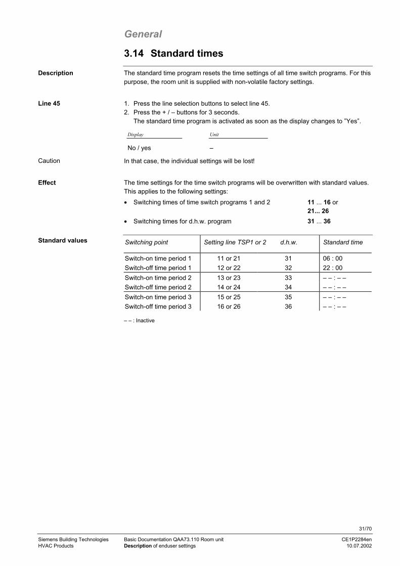
3.14 Standard times
The standard time program resets the time settings of all time switch programs. For thispurpose, the room unit is supplied with non-volatile factory settings.
1. Press the line selection buttons to select line 45.2. Press the + / – buttons for 3 seconds.
The standard time program is activated as soon as the display changes to ”Yes”.
Display Unit
No / yes –
In that case, the individual settings will be lost!
The time settings for the time switch programs will be overwritten with standard values.This applies to the following settings:• Switching times of time switch programs 1 and 2 11 ... 16 or
21... 26• Switching times for d.h.w. program 31 ... 36
Switching point Setting line TSP1 or 2 d.h.w. Standard time
Switch-on time period 1 11 or 21 31 06 : 00Switch-off time period 1 12 or 22 32 22 : 00Switch-on time period 2 13 or 23 33 – – : – –Switch-off time period 2 14 or 24 34 – – : – –Switch-on time period 3 15 or 25 35 – – : – –Switch-off time period 3 16 or 26 36 – – : – –
– – : Inactive
Description
Line 45
Caution
Effect
Standard values

32/70
Siemens Building Technologies Basic Documentation QAA73.110 Room unit CE1P2284enHVAC Products Description of enduser settings 10.07.2002
3.15 Summer / winter changeover temperature
The summer / winter changeover temperature is the criterion for automatic summer /winter changeover of the heating plant.It offers the following benefits:• Fully automatic operation throughout the year• The heating will not be switched on when the outside temperature drops for short
periods of time• Additional savings function
1. Press the line selection buttons to select line 46.2. Press the + / – buttons to select the summer / winter changeover temperature.
Setting range Unit Factory setting
8 ... 30.0 °C 17
By changing the setting, the respective periods of time will be shortened or extended.The change will only affect the heating circuit.
Entry:Increase: Winter operation will start earlier
Summer operation will start later .
Decrease: Winter operation will start laterSummer operation will start earlier
To determine changeover, the setting of the summer / winter changeover temperature( ± a fixed switching differential) is compared with the attenuated outside temperature.
Heating OFF (from winter to summer) TAged > SuWi +1 °C
Heating ON (from summer to winter) TAged < SuWi -1 °C
• This function only acts in automatic mode • During summer operation, Info line 4 Eco is displayed
ON
17
T
SuWi
TAged°C
H
OFFt
2284
D04
en
SuWi +1 °C
SuWi -1 °C16
18
19
20
50 10 15
Changeover between summer and winter operation:TAged Attenuated outside temperatureSuWi Summer / winter changeover temperatureT Temperaturet Time in daysH Heating
Description
Line 46
Effect
Changeover
Notes

33/70
Siemens Building Technologies Basic Documentation QAA73.110 Room unit CE1P2284enHVAC Products Description of enduser settings 10.07.2002
3.16 Language
There is a choice of languages for the display.
1. Press the line selection buttons to select line 47.2. Press the + / – buttons to select the required language.
Setting range Factory setting
German, English ... GermanThe assignment of other languages depends on the relevant software release. Theycan be selected by pressing the + / – buttons again.
3.17 Indication of faults
The room unit indicates faults that may have occurred in the unit itself or in the system.Faults cannot be reset. They will be cleared only when rectified.
Press the Info button to select Info line 2, or the line selection buttons to select line 50.
If a fault is indicated, the fault / status code symbol flashes. The fault can be displayedin clear text by pressing the Info button. The fault automatically displayed is always thefault with the highest priority (most severe fault). If other faults are present at the sametime, the next fault with the highest priority will be displayed after the present fault hasbeen corrected.In the case of a room unit-specific fault or a fault of Siemens boiler control, the errorcode and appropriate error text will be displayed.
2284
z25
Example of own fault display
In the event of a fault occurring on a boiler control system of other manufacture, theerror code delivered is preceded by #.
2284
z26
Example of other fault display
Error code Display QAA73.110 Description of error
0 No error No error10 OutsideSens Fault outside sensor60 Room sensor Fault room sensor100 TimeMaster No valid external time (yearly clock)118 W-Press low Water pressure too low124 Boiler temp Alarm boiler temperature (too high)131 Burn lockout Fault burner142 OpenTherm Missing partner unit on LPB150 BMU General BMU fault153 Interlock Boiler control interlocked162 AirPressSwi Fault air pressure switch
Description
Line 47
Description
Info line 2 or line 50
Effect
Own displays
Other displays
Error code list

34/70
Siemens Building Technologies Basic Documentation QAA73.110 Room unit CE1P2284enHVAC Products Description of enduser settings 10.07.2002
Depending on the type of boiler control, the room unit also displays other error codeswith the relevant error text. For detailed information, please refer to the technicaldocumentation of the boiler controller used.
3.18 Boiler status code
The room unit displays status codes that are generated by Siemens boiler control andthen transmitted via the OpenTherm bus. They will be cleared only when rectified.
Press the Info button to select Info line 3.
If a status code is indicated, the fault / status code symbol flashes.When pressing the Info button, the relevant status code is displayed in clear text.
Display QAA73.110 Description of error
None No service requiredMaintenance Boiler or burner service requiredChimney sweep Chimney sweep function active
Controller stop Controller stop function active
Setting Vo LF Low-fire setting Vo is active
Setting Vo HF High-fire setting Vo is active
Para-mode Unit is in parameter setting modeFloor Unit performes floor curing functionModem Standby by external BMU contactBMU Service non-Siemens boiler control required
Other fault displays
Description
Info line 3
Effect
Status display:

35/70
Siemens Building Technologies Basic Documentation QAA73.110 Room unit CE1P2284enHVAC Products Description of the heating engineer settings 10.07.2002
4 Description of the heating engineersettings
Service values
4.1 Current room temperature setpoints
Depending on the operating mode, the room temperature is maintained either at thenominal setpoint (TRN), the reduced setpoint (TRRw), or the frost protection setpoint(TRF).These parameters show the current setpoints of heating circuits 1 and 2.
Press the line selection buttons to select line 51 (HC1) or 52 (HC2).
Line Display Unit Setpoint
51 4 ... 35.0 °C HK1
52 4 ... 35.0 °C HK2
4.2 Attenuated outside temperature
The attenuated outside temperature is the simulated room temperature of a fictivebuilding that has no internal heat source. This means that it is only the outsidetemperature that affects the room temperature. Consideration is given to the building’sthermal storage capacity.The attenuated outside temperature is generated by the room unit. It is continuallycalculated based on the prevailing outside temperature.
Operating line 53 automatically displays the actual value [°C] of the attenuated outsidetemperature. No direct setting can be made.The generation of the attenuated outside temperature cannot be influenced.
Display Unit
–50 ... +50 °C
It is possible, however, to reset the attenuated outside temperature:1. Press the line selection buttons to select line 53.
2. Press the + / – buttons for 3 seconds.As soon as the display stops flashing, the attenuated outside temperature is resetto the actual outside temperature.
The attenuated outside temperature affects directly only summer / winter changeover.The attenuated outside temperature acts indirectly on flow temperature control via thecomposite outside temperature.
Description
Line 51, 52
Description
Line 53
Resetting
Effect

36/70
Siemens Building Technologies Basic Documentation QAA73.110 Room unit CE1P2284enHVAC Products Description of the heating engineer settings 10.07.2002
13
14
15
16
17
2371
D11
18:00 06:00 06:00 18:0018:00 h
TA°C
TAakt
TAged
Attenuated outside temperatureTAakt Actual outside temperatureTAged Attenuated outside temperature
4.3 Composite outside temperature
The composite outside temperature is a mixture of the actual outside temperature andthe attenuated outside temperature as calculated by the room unit.It is used as a compensating variable for flow temperature control.
Operating line 54 automatically displays the actual value [°C] of the composite outsidetemperature. No direct setting can be made.
Display Unit
-50 ... +50 °C
The composite outside temperature as a compensating variable acts on flowtemperature control, that is thus matched to the prevailing weather conditions.It also acts on the 24-hour heating limit to shut down the heating.
13
14
15
16
17
2371
D12
18:00 06:00 06:00 18:0018:00 t
TA TAakt
TAged
°C TAgem1TAgem0
Composite outside temperatureTAakt Actual outside temperatureTAged Attenuated outside temperatureTAgem1 Composite outside temperature for light building structuresTAgem0 Composite outside temperature for heavy building structures
Description
Line 54
Effect

37/70
Siemens Building Technologies Basic Documentation QAA73.110 Room unit CE1P2284enHVAC Products Description of the heating engineer settings 10.07.2002
4.4 Actual value 2 of d.h.w. temperature
The current d.h.w. temperature of the second d.h.w. sensor is displayed.
Press the line selection buttons to select line 55.
Display Unit
0 ... 127 °C
4.5 D.h.w. flow rate
The flow rate currently passing through the d.h.w. circuit is displayed.
Press the line selection buttons to select line 56.
Display Unit
0 ... 16 l/min
4.6 Actual boiler return temperature
The current boiler return temperature is displayed.
Press the line selection buttons to select line 57.
Display Unit
–40 ... +127 °C
4.7 Actual value of the flue gas temperature
The current flue gas temperature is displayed.
Press the line selection buttons to select line 58.
Display Unit
–40 ... +500 °C
4.8 Actual value of solar collector temperature
The current solar collector temperature is displayed.
Press the line selection buttons to select line 59.
Display Unit
–40 ... +250 °C
Description
Line 55
Description
Line 56
Description
Line 57
Description
Line 58
Description
Line 59

38/70
Siemens Building Technologies Basic Documentation QAA73.110 Room unit CE1P2284enHVAC Products Description of the heating engineer settings 10.07.2002
4.9 Actual value of solar storage tanktemperature
The current solar storage tank temperature is displayed.
Press the line selection buttons to select line 61.
Display Unit
–40 ... +127 °C
4.10 OpenTherm mode
For communication between the QAA73.110 and boiler control, the OpenThermprotocol is used.OpenTherm differentiates between 2 modes, Plus and Lite:• In OpenTherm Plus mode, the QAA73.110 can read or write various standardized
objects via the bus• In OpenTherm Lite mode, the QAA73.110 delivers only one signal to the boiler
control for controlling the heat output. In the event of fault, boiler control signalsBoiler Lock-Out Fault to the QAA73.110
Press the line selection buttons to select line 62.
Display Unit
Lite, Plus –
Directly after connection of OpenTherm, the QAA73.110 ascertains whether boilercontrol supports the OpenTherm Plus or the OpenTherm Lite protocol.The protocol currently used will automatically be displayed on this line.
Lite OpenTherm Lite protocol is usedPlus OpenTherm Plus protocol is used
4.11 Current flow temperature setpoint HC1 andHC2
The current flow temperature setpoint is displayed. For heating circuit 1 on line 63, forheating circuit 2 on line 64.
Press the line selection buttons to select line 63 or 64.
Display Unit
0...100 °C
Description
Line 61
Description
Line 62
Effect
Description
Line 63, 64

39/70
Siemens Building Technologies Basic Documentation QAA73.110 Room unit CE1P2284enHVAC Products Description of the heating engineer settings 10.07.2002
Space heating
4.12 Heating curve slope
The room unit generates the flow temperature setpoint based on the selected heatingcurve.The result is a constant room temperature irrespective of outside temperaturevariations.
1. Press the line selection buttons to select line 70 (for HC1) or line 80 (for HC2).
2. Press the + / – buttons to select the heating curve slope or --.-
Setting range Unit Factory setting
--.- / 2.5 ... 40.0 Increment 15.0
By changing the setting, the slope of the heating curve will be increased or decreasedwith the following effects:Increase: The flow temperature will be raised when the outside temperaturedropsDecrease: The flow temperature will be raised less when the outside
temperature dropsThe following settings produce the following effects:2.5 ... 40.0 The room unit delivers a weather-compensated flow temperature for
the respective heating circuit.– – . – The relevant heating circuit is deactivated.
• HC1 can be deactivated only if HC2 is also deactivated or does not exist• Line 80 is visible only if a second heating circuit exists and if it is supported by boiler
control
20 10 0 -10 -20 -30
90
80
70
60
50
40
30
°C
°C
40 35 30 27,5 25 22,5
20
17,5
15
12,5
10
7,5
5
2,5
100
2000
D07
TA
TV
Heating circuit diagramTV Flow temperatureTA Composite outside temperature
Description
Line 70 for HC 1Line 80 for HC 2
Effect
Note

40/70
Siemens Building Technologies Basic Documentation QAA73.110 Room unit CE1P2284enHVAC Products Description of the heating engineer settings 10.07.2002
4.13 Minimum and maximum limitation of flowtemperature HC1 and HC2
Minimum and maximum limitation define the range within which the flow temperaturesetpoint may vary. They prevent too low or too high flow temperatures.
1. Press the line selection buttons to select line 71, 72, 81 or 82.2. Press the + / – buttons to set the required limitations of the flow temperature.
Line Setting range Unit Factory setting
71 8...TV1max °C 872 TV1min...TKmax °C 8081 8...TV2max °C 882 TV2min...TKmax °C 80
...TKmax Maximum boiler temperatureTV1max Maximum limitation of flow temperature HC1TV1min ... Minimum limitation of flow temperature HC1TV2max Maximum limitation of flow temperature HC2TV2min Minimum limitation of flow temperature HC2
0 10 20 30 40 50 60 70 80 90 100
TV
max
min
akt
°C
2284
Z21
TVw
71/81
72/82
TVw Current flow temperature setpoint71 minimum limitation of flow temperature72 maximum limitation of flow temperature81 minimum limitation of flow temperature82 maximum limitation of flow temperature
These settings provide maximum or minimum limitation of the flow temperature.
Maximum limitation is not to be regarded as a safety function as required withunderfloor heating systems, for example.
Description
Lines71 and 72 for HC181 and 82 for HC2
Effect
Important

41/70
Siemens Building Technologies Basic Documentation QAA73.110 Room unit CE1P2284enHVAC Products Description of the heating engineer settings 10.07.2002
4.14 Parallel displacement of heating curveHC1/HC2
A parallel displacement of the heating curve ensures a better match of roomtemperature setpoint and actual room temperature.
1. Press the line selection buttons to select line 73 or 83.2. Press the + / – buttons to set the parallel displacement..
Line HK Setting range Unit Factory setting
73 1 –4.5...+4.5 °C 0.083 2 –4.5...+4.5 °C 0.0
By changing the value entered, all room temperature setpoints will be appropriatelyraised or lowered. This allows the room temperature setpoints to be matched to theeffective room temperatures.
If a nominal room temperature setpoint of 20 °C adjusted on the room unit alwaysproduces a room temperature of 22 °C (independent of the prevailing outsidetemperature), the heating curve should be displaced downward by 2 °C.
Each setpoint readjustment, be it by changing the setting value or the operational level,corresponds to a parallel displacement of the heating curve.
20 10 0 -10 -20 -30
90
80
70
60
50
40
30
°C
°C
2406
D02
100
0
1010
0
30
TRw
TA
TV
TV Flow temperatureTA Composite outside temperatureTRw Room temperature setpoint
Description
Line 73, 83
Effect
Example
Parallel displacement

42/70
Siemens Building Technologies Basic Documentation QAA73.110 Room unit CE1P2284enHVAC Products Description of the heating engineer settings 10.07.2002
4.15 Type of building construction
Enables the control system's rate of response to be matched to the type of buildingconstruction.
1. Press the line selection buttons to select line 74.2. Press the + / – buttons to select the type of building construction.
Setting range Unit Factory setting
Heavy, light – Light
When the outside temperature varies, the room temperature changes at different rates,depending on the building's thermal storage capacity.The above setting ensures that the generation of the composite outside temperaturewill be matched to the type of building construction. Also refer to ” Composite outsidetemperature”.Entry:
Heavy building structures:The room temperature will respond slower to outside temperaturevariations
Light Light building structures:The room temperature will respond quicker to outside temperaturevariations
• Heavy building structures:Buildings with thick walls or with external insulation
• Light building structures:Buildings with a light envelope
4.16 Room influence
Owing to the temperature checkback signal received from the room, a constant roomtemperature is maintained and, if required, boost heating or quick setback enabled.The parameter defines the room influence on the control of the heating circuits.Room temperature deviation is the temperature differential between actual roomtemperature and room temperature setpoint.
1. Press the line selection buttons to select line 75.2. Press the + / – buttons to select the room influence.
Setting range Unit Factory setting
None, on HC1, on HC2,on HC1 + HC2
– On HC1
The setting will activate the room influence on the required heating circuits.
None Room influence inactive: The measured room temperature will notaffect temperature control
Description
Line 74
Effect
Building construction
Description
Line 75
Effect
Entry:

43/70
Siemens Building Technologies Basic Documentation QAA73.110 Room unit CE1P2284enHVAC Products Description of the heating engineer settings 10.07.2002
On HC1 Room influence acting on heating circuit 1: The measured roomtemperature has an impact on temperature control of heating circuit 1(OpenTherm Lite mode)
On HC2 Room influence acting on heating circuit 2: The measured roomtemperature has an impact on temperature control of heating circuit 2
On HC1+HC2 Room influence acting on heating circuits 1 and 2:The measured room temperature has an impact on temperaturecontrol of both heating circuits
Deviations of the actual room temperature from the setpoint are acquired and taken intoaccount by temperature control.To be able to use the control variant "Weather compensation with room influence", thefollowing conditions must be satisfied:• An outside sensor must be connected to boiler control• Room influence must be enabled to act on the relevant heating circuits• There may be no thermostatic radiator valves in the reference room (If such
valves are present, they must be set to their fully open position).
4.17 Switching differential of the roomtemperature
It is used for room temperature limitation. This function is recommended for pumpheating circuits and prevents the rooms from getting overheated.
1. Press the line selection buttons to select line 76.2. Press the + / – buttons to set the room temperature switching differential.
Setting range Unit Factory setting
– – . –0.5...4.0
–°C
0.5
The switching differential for 2-position control will be changed.Entry:– – . – Switching differential is inaktiv
• The pump always remains activatedDecrease: Switching differential will become smaller
• The pumps are switched on and off more often• The room temperature varies within a narrower band
Increase: Switching differential will become greater• The pumps are switched on and off less often• The room temperature varies within a wider band
Room influence
Description
Line 76
Effect

44/70
Siemens Building Technologies Basic Documentation QAA73.110 Room unit CE1P2284enHVAC Products Description of the heating engineer settings 10.07.2002
With pump heating circuits, the amount of heat supplied is controlled by switching thepumps on and off. This is accomplished with 2-position control by means of the roomtemperature's switching differential.
OFF
ONP
°CTRx
TRw+SDR
2371
D02
TRw
t
Pump ON TRx = TRwPump OFF TRx = TRw + SDR
°C
2284
Z20
ON
OFF
w TRx
P
[ ]
76
The heating circuit pumps are controlled not directly by the QAA73.110, but by boilercontrol. For this reason, this functionality is not ensured by the room unit alone.
4.18 Adaption of the heating curve
The adaption facility learns from the different heating situations and matches the controlto the heating circuit at regular intervals. Adaption of the heating curve takes placeautomatically, which means that it need not be adjusted manually.
1. Press the line selection buttons to select line 77.1. Press the + / – buttons to select the type of heating curve adaption.
Setting range Unit Factory setting
Inactive / active – Active
The setting will switch automatic adaption of the heating curve on or off.
Entry:Inactive No adaption:
The heating curve settings are maintained.Active Automatic adaption:
The heating curve will automatically be adapted as soon as theoperating level ”Nominal room temperature setpoint” is used.
Adaption acts according to line 75 ”Room influence”.
Room temperaturecontrol
Functioning
Switching differential
Note
Description
Line 77
Effect
Note
Legend
TRx Actual value of the roomtemperature
TRw Room temperature setpointSDR Switching differential of room
temperatureP Pump (ON / OFF)w Setpoint
Switch-on point
Legend
TRx Actual value of the roomtemperature
TRw Room temperature setpointSDR Switching differential of
room temperatureON Switch-on point

45/70
Siemens Building Technologies Basic Documentation QAA73.110 Room unit CE1P2284enHVAC Products Description of the heating engineer settings 10.07.2002
The adaption facility automatically matches the heating curve to the type of buildingconstruction and the heating requirements. Adaption gives consideration to roomtemperature deviations, outside temperature characteristics and adaption sensitivity.
To achieve an optimum adaptation, the following situations should occur as rarely aspossible - especially after commissioning - since this would reset certain calculationsrequired for the adaptation:− Manual correction of heating curve− Power failure− Changes to the room temperature setpoint
Every day at midnight, the room temperature control differential of the previous day isevaluated. This evaluation leads to an automatic readjustment of the heating curve.• Simple adaption (range )
At attenuated outside temperatures below 4 °C, it is only the slope of the heatingcurve that is adapted.In this temperature range, the readjustment is weighted with factor f2 and adaptionsensitivity 2.
• Combined adaption (range )At attenuated outside temperatures of between 4 and 12 °C, it is partly the slopeand partly the parallel displacement that are adapted.In this temperature range, the readjustment of the parallel displacement is weighedwith factor f1 and adaption sensitivity 1.In this temperature range, the readjustment of the slope is weighted with factor f2and adaption sensitivity 2.
• No adaption (range )At attenuated outside temperatures above 12 °C, the heating curve will not beadapted
Example using a nominal room temperature setpoint of 20 °C.
0
2371
D07
TA12 4 -4 -12
0,5
1
f
20ged
f1
f2
ZAF1 ZAF2
f Factorf1 Factor for parallel displacementf2 Factor for slopeTAged Attenuated outside temperatureZAF1 adaption sensitivity 1ZAF2 adaption sensitivity 2
Adaption
Note
Process
Diagram
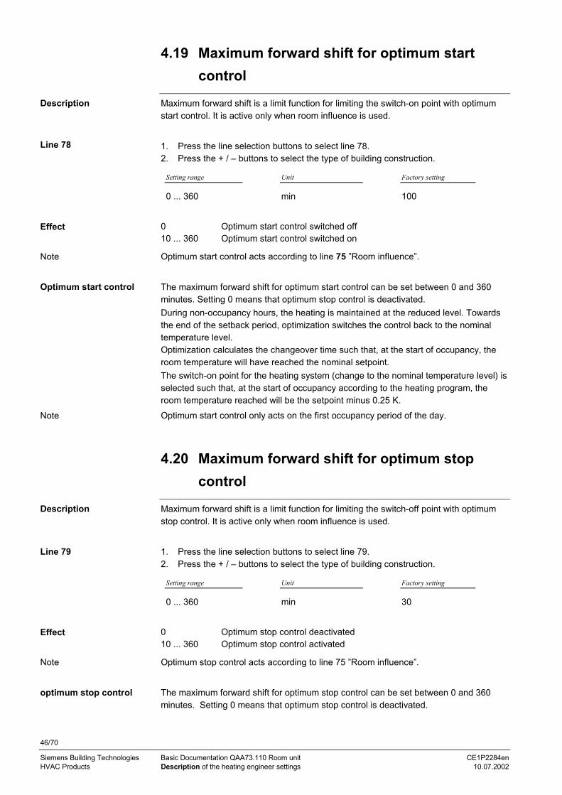
46/70
Siemens Building Technologies Basic Documentation QAA73.110 Room unit CE1P2284enHVAC Products Description of the heating engineer settings 10.07.2002
4.19 Maximum forward shift for optimum startcontrol
Maximum forward shift is a limit function for limiting the switch-on point with optimumstart control. It is active only when room influence is used.
1. Press the line selection buttons to select line 78.2. Press the + / – buttons to select the type of building construction.
Setting range Unit Factory setting
0 ... 360 min 100
0 Optimum start control switched off10 ... 360 Optimum start control switched on
Optimum start control acts according to line 75 ”Room influence”.
The maximum forward shift for optimum start control can be set between 0 and 360minutes. Setting 0 means that optimum stop control is deactivated.During non-occupancy hours, the heating is maintained at the reduced level. Towardsthe end of the setback period, optimization switches the control back to the nominaltemperature level.Optimization calculates the changeover time such that, at the start of occupancy, theroom temperature will have reached the nominal setpoint.The switch-on point for the heating system (change to the nominal temperature level) isselected such that, at the start of occupancy according to the heating program, theroom temperature reached will be the setpoint minus 0.25 K.Optimum start control only acts on the first occupancy period of the day.
4.20 Maximum forward shift for optimum stopcontrol
Maximum forward shift is a limit function for limiting the switch-off point with optimumstop control. It is active only when room influence is used.
1. Press the line selection buttons to select line 79.2. Press the + / – buttons to select the type of building construction.
Setting range Unit Factory setting
0 ... 360 min 30
0 Optimum stop control deactivated10 ... 360 Optimum stop control activated
Optimum stop control acts according to line 75 ”Room influence”.
The maximum forward shift for optimum stop control can be set between 0 and 360minutes. Setting 0 means that optimum stop control is deactivated.
Description
Line 78
Effect
Note
Optimum start control
Note
Description
Line 79
Effect
Note
optimum stop control

47/70
Siemens Building Technologies Basic Documentation QAA73.110 Room unit CE1P2284enHVAC Products Description of the heating engineer settings 10.07.2002
During occupancy hours, the heating is maintained at the nominal level. Towards theend of the occupancy time, the control switches to the reduced level.Optimization calculates the changeover time such that, at the end of occupancy time,the room temperature will be 0.5 °C below the nominal setpoint (early shut-down).
Optimum stop control only acts on the last occupancy period of the day.
D.h.w.
4.21 Reduced setpoint of the d.h.w. temperature
Reduction of the d.h.w. temperatures outside main occupancy times.The time switch integrated in the room unit automatically switches between main andsecondary occupancy times.D.h.w. is at a high temperature level only if required. This saves energy by reducing thetemperature when not in use.
1. Press the line selection buttons to select line 90.2. Press the + / – buttons to adjust the reduced setpoint of the d.h.w. temperature.
Setting range Unit Factory setting
8...TBWw °C 40
TBWw Nominal d.h.w. temperature setpoint
The temperature setpoint during reduced d.h.w. operation will be changed.
0 10 20 30 40 50 60 70 80 90 100 120 130 140 °C
2284
Z23
90 1307
7 Nominal d.h.w. temperature setpoint90 Reduced setpoint of the d.h.w. temperature130 Maximum nominal setpoint of d.h.w. temperature
D.h.w. heating has 2 different setpoints that can be used:
• Nominal d.h.w. temperature setpointProduces the d.h.w. temperature required during the main occupancy times
• Reduced setpoint of the d.h.w. temperatureProduces the d.h.w. temperature required outside the main occupancy times
The periods of time during which these d.h.w. temperature setpoints shall be used canbe set on line 91.
4.22 Release of d.h.w. heating
Makes it possible to limit the period of time during which d.h.w. heating at the nominalsetpoint is released. D.h.w. heating at the nominal setpoint can thus be released asrequired by the users.
Note
Description
Line 90
Effect
D.h.w. temperaturesetpoints
Description

48/70
Siemens Building Technologies Basic Documentation QAA73.110 Room unit CE1P2284enHVAC Products Description of the heating engineer settings 10.07.2002
1. Press the line selection buttons to select line 91.2. Press the + / – buttons to enter the required period of time during which d.h.w.
heating at the nominal setpoint shall be released.
Setting range Unit Factory setting
24h / day, TSP HC – 1hTSP HC, TSP d.h.w.
– TSP HC – 1h
The setting defines the period of time during which d.h.w. heating at the nominalsetpoint is released. Outside this period of time, the reduced d.h.w. setpoint applies.There is one exception, however, function ”D.h.w. push” (function with no setting).Release of d.h.w. heating to the nominal setpoint takes place when using the followingsettings:
24 h/day 24 hours per day
TSP HC – 1h According to the heating circuit time switch program(s) with a forwardshift of one hour
TSP HC According to the heating circuit time switch program(s)
TSP d.h.w. According to the d.h.w. time switch program
4.23 Legionella function
The legionella function ensures that the d.h.w. in the storage tank will periodically beraised to a temperature of at least 60 °C, thus making certain that potential legionellaviruses will be killed.
When using d.h.w. systems with instantaneous heaters, this function may not beactivated!
1. Press the line selection buttons to select line 92.2. Press the + / – buttons to activate or deactivate the legionella function.
Setting range Unit Factory setting
off / weekly/ daily – weekly
The setting activates or deactivates the legionella function.Entry:OFF Function inactive
Weekly ON: Function is activated every Monday morning when d.h.w. is heatedup for the first time and lasts a maximum of 2.5 hours. The d.h.w. isheated up to the adjusted legionella setpoint.
Daily Function is activated every day when d.h.w. is heated up for the first timeand lasts a maximum of 2.5 hours. The d.h.w. is heated up to the adjustedlegionella setpoint.
• If on the starting day of the legionella function, d.h.w. is not heated, or if the functionis aborted, it will be repeated the next day when d.h.w. is heated for the first time.
• This function is possible only when d.h.w. heating is released by the d.h.w. heatingprogram.
Line 91
Effect
Description
Important
Line 92
Effect
Notes

49/70
Siemens Building Technologies Basic Documentation QAA73.110 Room unit CE1P2284enHVAC Products Description of the heating engineer settings 10.07.2002
4.24 D.h.w. operating mode selector
The operating mode button for d.h.w. on the controller front can be extended by thed.h.w. operating mode ”ON eco”. This additional operating mode is used for d.h.w.systems with instantaneous heating. Also refer to section "D.h.w. operating mode".
1. Press the line selection buttons to select line 93.2. Press the + / – buttons to release or lock operating mode “ON eco”.
Setting range Unit Factory setting
Without ECO / With ECO – Without ECO
When using setting ”With ECO”, the user can also select operating mode ”ON Eco” viathe d.h.w. operating mode button.
4.25 Control of d.h.w. circulating pump
The d.h.w. circulating pump is used for circulating the d.h.w. D.h.w. circulation preventsthe d.h.w. from cooling down by the time it reaches the consumer. With this setting, thetemporal dependence for operation of the circulating pump can be selected.
Setting range Unit Factory setting
Release of d.h.w. / Prog 2 – D.h.w. program
Release of d.h.w. – according to d.h.w. releaseThe d.h.w. circulating pump is activated and deactivated according to the d.h.w. releaseselected on line 91. During that period of time, the circulating pump operatescontinuously, without giving consideration to actual d.h.w. heating.
Prog 3 – according to time switch program 3The d.h.w. circulating pump is controlled according to the switching times of time switchprogram 3. It is thus possible to operate the circulating pump only during the times ofusage individually set.
Prog 2 - according to time switch program 2The d.h.w. circulating pump is controlled according to the switching times of time switchprogram 2. It is thus possible to operate the circulating pump only during individually settimes of usage.The circulating pump does not follow any forward shift. This means it is operated inaccordance with the actual times of usage.
General
4.26 Programming
If the parameter values shall not be changed, entry can be locked.
1. Press the line selection buttons to select line 95.2. Press the + / – buttons to activate or deactivate programming.
Description
Line 93
Effect
Description
Line 94
Forward shift
Description
Line 95

50/70
Siemens Building Technologies Basic Documentation QAA73.110 Room unit CE1P2284enHVAC Products Description of the heating engineer settings 10.07.2002
Setting range Unit Factory setting
Locked / released – Released
Released The parameter values can be changed.
locked The parameter values can still be displayed, but changes are no longerpossible.When pressing the + / – buttons, the display shows symbol in place ofthe value.
On the programming or parameter setting level, locked programming can temporarilybe deactivated. To do this, the down button () and the (+) button must be pressedsimultaneously for at least 3 seconds. This temporary cancellation of the programminglock is maintained until the next change to the Info level is made.To have programming continuously released, the down button () and the (+) buttonmust be pressed simultaneously for at least 3 seconds. Then, parameter”Programming” can be set to released.
Effect
Temporary cancellation ofprogramming
Continuous cancellation ofprogramming

51/70
Siemens Building Technologies Basic Documentation QAA73.110 Room unit CE1P2284enHVAC Products Description of the heating engineer settings 10.07.2002
4.27 Clock time master
The clock time of the QAA73.110 and the clock time of the connected boiler control canbe synchronized. In that case, one of the units will be defined as the clock time master,and the other unit adopts the time of day from the master.
1. Press the line selection buttons to select line 96.2. Press the + / – buttons to define the clock time master.
Setting range Unit Factory setting
QAA73, external – QAA73
The setting defines the clock time master.
Display:QAA73 QAA73.110 is the clock time master. OpenTherm transmits the time of day to
the boiler control, either periodically or after an adjustment.ExternallyThe QAA73.110 adopts the time of day periodically (every 5 minutes) from
the boiler control. In that case, the time of day cannot be readjusted on theQAA73.110.
4.28 Winter- / summertime changeover
This function enables the yearly clock to automatically switch to wintertime.
1. Press the line selection buttons to select line 97.2. Press the + / – buttons to set the date of changeover.
Setting range Unit Factory setting
1. Jan ... 31. Dec dd.mm 25. March
On the Sunday following the set date, the time of day of the room unit will switch tosummertime. For that purpose, the time of day is shifted forward by one hour.
In compliance with international standards, the change from winter- to summertime ismade on the last Sunday in March, and the change from summer- to wintertime on thelast Sunday in October. The factory setting of the room unit meets this requirement asthe Sundays in question lie in the adjustable period of time between the factory settingand the last day of the relevant month.
Description
Line 96
Effect
Description
Line 97
Effect
International standards

52/70
Siemens Building Technologies Basic Documentation QAA73.110 Room unit CE1P2284enHVAC Products Description of the heating engineer settings 10.07.2002
4.29 Summer- / wintertime changeover
This function enables the yearly clock to automatically switch to wintertime.
1. Press the line selection buttons to select line 98.2. Press the + / – buttons to set the date of changeover.
Setting range Unit Factory setting
1. Jan ... 31. Dec dd.mm 25. Oct
On the Sunday following the set date, the time of day of the room unit will switch towintertime.For that purpose, the time of day is shifted backward by one hour.
Description
Line 98
Effect

53/70
Siemens Building Technologies Basic Documentation QAA73.110 Room unit CE1P2284enHVAC Products Description of the OEM settings 10.07.2002
5 Description of the OEM settingsSpace heating OEM5.1 Maximum setpoint (TRwMax) and minimum
setpoint (TRwMin) of room temperature
The nominal setpoint of the room temperature can be adjusted within a certain settingrange. That setting range is limited by the maximum room temperature setpoint(TrwMax) and the minimum room temperature setpoint (TrwMin).
1. Press the line selection buttons to select line 100 or 101.2. Press the + / – buttons to set the maximum rate of increase.
Line Setting range Unit Factory setting
100 TRwMin ... 35 °C 35
101 4... TRwMax °C 10
The upper or lower limit of the nominal room temperature setpoint will be changed.
5.2 Gain factor of room influence (KORR)
Defines the influence of room temperature setpoint deviations on the controlled system.The room influence can be activated and deactivated (operating line 75).
1. Press the line selection buttons to select line 102.2. Press the + / – buttons to set the gain factor.
Setting range Unit Factory setting
0...20 – 4
Changing this setting has the following impact:Increase: Authority of room influence will increaseDecrease: Authority of room influence will decrease
The following example shows how and according to which formula the roomtemperature setpoint will be corrected.
Room temperature setpoint TRw = Actual room temperatureTRx = 22 °C
Correction factor KORR = 8
TRwk = TRw + KORR2
(TRw - TRx)
TRwk = 20 °C + 4 (20 °C – 22 °C) = 12 °C
KORR Constant for room influence TRx Actual value of the room temperature TRw Room temperature setpoint TRwk Room temperature setpoint (readjusted)
Description
Line 100, 101
Effect
Description
Line 102
Effect
Correction
Example with formula

54/70
Siemens Building Technologies Basic Documentation QAA73.110 Room unit CE1P2284enHVAC Products Description of the OEM settings 10.07.2002
As the example shows, if the room temperature is 2 °C too high, the room influencetemporarily shifts the room temperature setpoint down to a level of 12 °C.
30252015105
30
25
20
15
10
5
TRwk [°C]
KORR=4
TRx
2284
d03
KORR=10 °C
TRw
The corrected room temperature setpoint
KORR works only if the room temperature influence on line 75 is activated.
5.3 Constant for quick setback (KON)
Quick setback takes advantage of the thermal storage capacity of a building. Theconstant for quick setback is only active in the case of quick setback of control systemswith no room influence.
1. Press the line selection buttons to select line 103.2. Press the + / – buttons to set the constant.
Setting range Unit Factory setting
0...20 – 2
The duration of quick setback will be changed.Entry:Increase: Setback time will become longer
For well insulated buildings that cool down slowly
Decrease: Setback time will become shorterFor poorly insulated buildings that cool down rather quickly
Quick setback is started as soon as a change to a lower room temperature setpointtakes place (e.g. switching times in automatic mode).
The heating circuit pump will be deactivated until the quick setback time has elapsed,which is the result of setting 103, the composite outside temperature and the roomtemperature setpoint jump.The quick setback time is limited to a maximum of 15 hours.
Example with graph
Note
Description
Line 103
Effect
Quick setback withno room influence

55/70
Siemens Building Technologies Basic Documentation QAA73.110 Room unit CE1P2284enHVAC Products Description of the OEM settings 10.07.2002
The example applies to a setpoint step change of 4 °C (e.g. TRw from 20 °C to 16 °C):
TAgem Setting on operating line 1030 4 8 12 15 20
–20 0 0 0 0 0 0
–10 0 0.5 h 1 h 1.5 h 2 h 2.5 h
0 0 3 h 6 h 9 h 11 h 15 h
+10 0 5 h 11 h 15 h 15 h 15 h
5.4 Boost of the room temperature setpoint(DTRSA)
This function temporarily raises the room temperature setpoint so that the room will beheated up quicker.
This function only acts on the heating circuits according to line 75.
1. Press the line selection buttons to select line 104.2. Press the + / – buttons to adjust the room temperature setpoint boost.
Setting range Unit Factory setting
0...20 °C (K) 5
The duration of boost heating will be changed.Entry:Increase: More setpoint boost
Heating up time will become shorter
Decrease: Less setpoint boostHeating up time will become longer
Boost heating is started as soon as switching to a higher room temperature setpointoccurs (e.g. switching times in automatic mode).The room temperature setpoint will be raised by the setting made on line 104 until theroom is heated up (TRw - ¼ °C).The boost produces an increase in the flow temperature setpoint.
20
15
°C
t
TR w
TRx
2284
z24
a b
104
TRx Actual value of the room temperatureTRw Room temperature setpoint104 Setpoint boostt Time
Example
Description
Note
Line 104
Effect
Boost heating

56/70
Siemens Building Technologies Basic Documentation QAA73.110 Room unit CE1P2284enHVAC Products Description of the OEM settings 10.07.2002
5.5 Limitation of rate of increase of flowtemperature setpoint
The rate of increase of the flow temperature setpoint indicates how quickly the flowtemperature setpoint may rise (in K per minute). It can be limited.The limitation set applies to both heating circuits.
1. Press the line selection buttons to select line 105.2. Press the + / – buttons to set the maximum rate of increase.
Setting range Unit Factory setting
0 ... 15 K/min 5
The rate of increase will be limited by the setting.
5.6 Measured value correction of roomtemperature
Calibration of the room sensor ensures that the display of the effective roomtemperature will be more accurate.
1. Press the line selection buttons to select line 106.2. Press the + / – buttons to select the required correction of the sensor characteristic.
Setting range Unit Factory setting
–3 ... +3 ºC 0
The sensor characteristic is displaced parallel by the selected value.When entering a negative value, the temperature measured will be lowered by thatvalue, when entering a positive value, it will be raised by that value.
D.h.w. OEM
5.7 Maximum d.h.w. setpoint (TBWmax)Function for limiting the nominal setpoint of the d.h.w. temperature. This yields thefollowing benefits:• Setting can be limited by the enduser• Reduced risk of scalding• Minimized susceptibility to scale
1. Press the line selection buttons to select line 130.2. Press the + / – buttons to adjust the maximum setpoint of the d.h.w. temperature.
Setting range Unit Factory setting
TBWw...80 °C 60
TBWw Nominal d.h.w. temperature setpoint
Description
Line 105
Effect
Description
Line 106
Effect
Description
Line 130

57/70
Siemens Building Technologies Basic Documentation QAA73.110 Room unit CE1P2284enHVAC Products Description of the OEM settings 10.07.2002
The setting will ensure maximum limitation of the nominal d.h.w. temperature setpoint.
A d.h.w. setpoint maximum (TBWmax) of a BMU transmitted via OpenTherm is givenpriority and replaces that of the controller (setting 130).
5.8 Setpoint of the legionella function
The setpoint of the legionella function is an adjustable temperature level to which thed.h.w. temperature is raised when the legionella function is activated, aimed at killingany legionella viruses that may have occurred.
1. Press the line selection buttons to select line 131.2. Press the + / – buttons to adjust the required setpoint.
Setting range Unit Factory setting
8...95 °C 65
The setting changes the d.h.w. setpoint during the period of time the d.h.w. is heatedup as a result of the legionella function.
5.9 Dwelling time at legionella function setpoint
The setpoint of the legionella function (operating line 92) is maintained for at least theperiod of time set here.Setting range Unit Factory setting
0...360 min 0
The dwelling time starts as soon as the legionella setpoint is reached.
During the entire dwelling time, the temperature may not fall below the legionellasetpoint by more than the set BMU d.h.w. switching differential (standard setting LMU).The legionella function is terminated when this criterion is met.
5.10 Effect of legionella function on the circulatingpump
Flushing the circulation piping ensures that the legionella viruses will also be killed inthat part of the plant.Setting range Unit Factory setting
No / yes Yes
No The circulating pump does not run during the time of the legionellafunction.
Yes The circulating pump runs during the time of the legionella function, evenif it would not be allowed to run based on control of the d.h.w. circulatingpump (setting 94).
If this function is deactivated, there is a risk that legionella viruses will return from thecirculation piping to the d.h.w. storage tank right after the storage tank has beenthermally desinfected.
Effect
Note
Description
Line 131
Effect
Description
Line 132
Effect
Description
Setting on operatingline 133
Effect
Important

58/70
Siemens Building Technologies Basic Documentation QAA73.110 Room unit CE1P2284enHVAC Products Description of the OEM settings 10.07.2002
Service functions OEM
5.11 Info display
The Info display can be made to appear continuously or temporarily.
1. Press the line selection buttons to select line 150.2. Press the + / - buttons to select the display mode.
Setting range Unit Factory setting
Temporary, continuously – Temporary
This setting selects the display mode of the Info display:When entering X:Temporary The information selected on the Info level is displayed for only 8
minutes. After that period of time, the display will return to the standarddisplay (actual room temperature, time of day and time pointer)
Continuously The information selected last with the Info button will be continuouslydisplayed.
5.12 Frost warning
A frost warning can be generated depending on a selectable outside temperature.
1. Press the line selection buttons to select line 151.2. Press the + / – buttons to select the required function.
Setting range Unit Factory setting
– – . – / –10 ... +10 °C 3.0
– – . – no frost warning
If the outside temperature falls to the selected temperature level or drops below it, theInfo display shows the actual outside temperature as a flashing value.
Description
Line 150
Effect
Description
Line 151
Note
Effect

59/70
Siemens Building Technologies Basic Documentation QAA73.110 Room unit CE1P2284enHVAC Products Description of the OEM settings 10.07.2002
5.13 Operation
Using this setting, operation can be locked or released.
1. Press the line selection buttons to select line 152.2. Press the + / – buttons to select the required function.
Setting range Unit Factory setting
Locked / released – Released
The following operating elements are now locked, thus preventing tampering:• Button for selecting the heating circuit’s operating mode• D.h.w. operating mode button• Setpoint knob for nominal temperature• Occupancy button
5.14 Action occupancy button
The action of the occupancy button can be restricted to heating circuit 1 or it can applyto both heating circuits.
1. Press the line selection buttons to select line 153.2. Press the + / – buttons to select the required function.
Setting range Unit Factory setting
On HC1 + HC2, on HC1 – On HC1 + HC 2
When pressing the occupancy button in automatic or continuous operation, either bothheating circuits or only heating circuit 1 is acted upon.
5.15 Software version
The software version installed represents the state of the software available at the timethe controller was produced. It is thus possible to identify the software version withoutremoving the unit.
Press the line selection buttons to select line 199.
Display Unit
00.0 ... 99.9 –
The software version will automatically be displayed on this line.Example: 01.0The first 2 digits give the software version The third digit gives the software revision
(01.0)
Description
Line 152
Effect
Description
Line 153
Effect
Description
Line 199
Effect

60/70
Siemens Building Technologies Basic Documentation QAA73.110 Room unit CE1P2284enHVAC Products Functions 10.07.2002
6 FunctionsThe functions described below require no settings. They are performed automaticallybut have an impact on the plant.For the rectification of faults, planning and plant maintenance, it may therefore be veryadvantageous to know about their impact on plant operation.
6.1 Types of compensation
The room unit offers 3 types of compensation each of which generates the effectiveflow temperature setpoint in a different way. They are the following:− Weather compensation− Weather compensation with room influence− Room compensation
If no outside sensor is connected and the room sensor of the QAA73.110 fails, a faultstatus signal will be delivered. In that case, the room unit will change to emergencyoperation ”with no sensor” to generate the flow temperature setpoint based on thecurrent room temperature setpoint and a fixed outside temperature of 0 °C
6.1.1 Weather compensation
With this type of compensation, the building’s heat losses are compensated by anadequate flow temperature.The colder the weather, the quicker the building cools down and the greater the heatingcircuit’s heat demand.With this type of compensation, it must be ensured that the heating curve is correctlyset, because the room unit gets no feedback from the space whether the amount ofheat supplied meets the demand of the users.
The room influence (line 75) must be set to ”None” and, in addition, an outside sensormust be connected.
6.1.2 Weather compensation with room influence
Compared to pure weather compensation, this type of compensation offers enhancedcomfort because with the room influence, the room unit gets a feedback from thespace.
The room influence (line 75) must be activated for the required heating circuits and, inaddition, an outside sensor must be connected.
The room influence acts on the room temperature setpoint. The deviation of setpoint /actual value of the room temperature is multiplied by the correction factor KORR/2 andadded to the deviation from the room temperature setpoint in the opposite direction. Room influence acts:• In the case of deviations of setpoint / actual value of the room temperature• With automatic or manual changeover to a higher or lower room temperature
setpoint
Introduction
Note
Description
Prerequisites
Description
Prerequisites
Room influence

61/70
Siemens Building Technologies Basic Documentation QAA73.110 Room unit CE1P2284enHVAC Products Functions 10.07.2002
6.1.3 Room compensation
With pure room compensation, a PID control algorithm is activated. This is thepreferred control mode if the room temperature is the only compensating variableavailable. The selected control algorithm gives consideration to both the actual value ofthe room temperature and the current slope (gradient). The P-part is generated by thecontrol deviation, the D-part from the gradient of the room temperature. The I-partsuppresses continuous deviations of setpoint / actual value.
The room influence (line 75) must be activated for the required heating circuits and, inaddition, no outside sensor may be connected.
The flow temperature and thus the room temperature are controlled as a function of theactual room temperature and its current development. For example, if the roomtemperature rises slightly, the flow temperature will immediately be reduced even ifthere is deviation of setpoint / actual value apparent yet. To prevent continuousdeviations, the I-part of PID control keeps the room temperature at the required level.
6.2 Automatic 24-hour heating limit
This is a fast-acting savings function since the heating is switched off when there is nomore demand for heat. Economical operation is ensured throughout the year sincemanual switching off is no longer required, especially during intermediate seasons.
• The automatic 24-hour heating limit does not function in continuous operation • When the 24-hour heating limit is activated, the Info line displays Eco
6.2.1 Without room influence
If no room influence is activated, the 24-hour heating limit switches depending on theflow temperature setpoint and the adjusted setpoint , or .
The temperature basis used for this function are the flow temperature setpoint and thecurrent room temperature setpoint.
If the flow temperature setpoint falls below the room temperature setpoint plus acorrection value, the heating will be switched off.Heating OFF:
TVw = TRw +2 S/10
If the flow temperature setpoint exceeds the room temperature setpoint plus acorrection value, the heating will be switched on.Heating ON:
TVw = TRw +4 S/10
TVw Flow temperature setpointTRw Room temperature setpoints Slope of the heating curve
Description
Prerequisites
Effect
Description
Notes
Introduction
Process
Switching off
Switching on

62/70
Siemens Building Technologies Basic Documentation QAA73.110 Room unit CE1P2284enHVAC Products Functions 10.07.2002
6.2.2 With room influence
If the room influence on the heating circuits is activated, the room influence readjuststhe flow temperature setpoint of the relevant heating circuits. In that case, the 24-hourheating limit switches depending on the corrected flow temperature setpoint and theadjusted setpoint , or .
The temperature basis used for this function are the values of the readjusted flowtemperature setpoint and of the current room temperature setpoint.
If the flow temperature setpoint corrected by the room influence falls below the roomtemperature setpoint plus a correction value, the heating will be switched off.• Heating’s switch-off point:
16KORR
10S
2TRw TVwk −+≤
If the flow temperature setpoint corrected by the room influence exceeds the roomtemperature setpoint plus a correction factor, the heating will be switched on.• Heating’s switch-on point:
16KORR
10S
4TRw TVwk −+≥
KORR Factor for room influence (line 102)TVwk Flow temperature setpoint corrected by the room temperatureTRw Room temperature setpoints Slope of the heating curve
Introduction
Process
Switching off
Switching on

63/70
Siemens Building Technologies Basic Documentation QAA73.110 Room unit CE1P2284enHVAC Products Functions 10.07.2002
6.3 Quick setback with room influence
The thermal storage capacity of a building is utilized when changing to a lower setpoint.The quick setback described here only acts on the heating circuits where roominfluence is active.
Quick setback is started as soon as a change to a lower room temperature setpointtakes place (e.g. switching times in automatic mode).Quick setback is terminated as soon as the actual room temperature reaches the levelof the respective room temperature setpoint (TRx = TRw).
20
15
°C
t
TRx
2284
d01
TRw
ON
OFF
H
t
TRx Actual value of the room temperatureTRw Room temperature setpointH Quick setback
Due to the readjustment of the room temperature setpoint, the heating circuit pump willbe switched off until the quick setback process is terminated. This means that the roomtemperature falls quicker since the supply of heat from the flow or boiler is cut off.
If no room influence is selected, quick setback will be provided not by this process butaccording to the quick setback function 103.
6.4 D.h.w. push
Availability of d.h.w. is also ensured during non-occupancy times.
If, due to unexpected demand, the d.h.w. storage tank is emptied, the d.h.w. pushprovides one-time charging of the storage tank until the nominal d.h.w. temperaturesetpoint is reached.The d.h.w. push is not active when instantaneous d.h.w. heating is used.
The d.h.w. push is triggered as soon as the actual d.h.w. temperature falls by morethan 10 °C below the reduced d.h.w. setpoint.
When the d.h.w. push is triggered, the d.h.w. is heated once until its nominaltemperature setpoint is reached.Then, the active d.h.w. program applies again.
Description
Process
Effect
Note
Benefit
Description
Exception
Process
Effect

64/70
Siemens Building Technologies Basic Documentation QAA73.110 Room unit CE1P2284enHVAC Products Functions 10.07.2002
t
2284
d02
TBWw
TBWR
TBWw
TBWR
2·SDBW
SDBW
SDBW
Push
TBWx
SDBW Switching differential d.h.w.TBWw Nominal d.h.w. temperature setpointTBWR Reduced setpoint of the d.h.w. temperature
6.5 Frost protection
Frost protection functions prevent plant and room temperatures from falling below acertain level, thus protecting the heating plant and the rooms from freezing.
6.5.1 Frost protection for the building
The room unit’s frost protection function ensures that the room temperature will not fallbelow the selected frost protection value as long as the heating plant operates.
6.5.2 Frost protection for the boiler and the d.h.w.
Frost protection for the boiler and the d.h.w. must be ensured by the boiler control.
Example
Description
Effect
Caution

65/70
Siemens Building Technologies Basic Documentation QAA73.110 Room unit CE1P2284enHVAC Products Dimensions 10.07.2002
7 Dimensions
2284
M02
96
96 91
47
96
1...292
+0.8
-0
92 +0.8-0 22
84M
01
96
Room unit
Panel cutout

66/70
Siemens Building Technologies Basic Documentation QAA73.110 Room unit CE1P2284enHVAC Products Technical data 10.07.2002
8 Technical data
OpenTherm BusTerminals 2-wire (interchangeable)Cable length max. 50 mCable resistance max. 2 x 5 Ω
Power consumption 30 mW (typically)
Safety class III to EN 60 730when mounted in compliance withregulations
Degree of protection of housing IP 20 to EN 60529Contamination environment to EN 60730
Operation IEC 721-3-3 class 3K 5Temperatures 0..0.50 °CHumidity < 85 % r.h.
Transport IEC 721-3-2 class 2K 3Temperatures -25...70 °CHumidity < 95 % r.h.
Storage IEC 721-3-1 class 1K 3Temperatures –25...70 °CHumidity < 95 % r.h.
conformityEMC directive 89/336/EEC– Immunity EN 50 082-1, EN 50 082-2– Emissions EN 50 081-1, EN 50 081-2Low voltage directive 73/23/EEC– Electrical safety EN 60 730-1, EN 60 730-2-9
Measuring range 0...45 °C
Backup of time switch min. 12 hSoftware class A to EN 60 730Weight approx. 0.17 kg
Operating voltage
Protection
Environmental conditions
Standards
Room sensor
Other features

67/70
Siemens Building Technologies Basic Documentation QAA73.110 Room unit CE1P2284enHVAC Products Index 10.07.2002
IndexAaction occupancy button............................................59actual boiler return temperature ................................37actual temperature of solar collector .........................37actual temperature of solar storage tank...................38actual value of d.h.w. temperature ............................37actual value of the boiler temperature .......................37actual value of the flue gas temperature .............35, 37adaption of the heating curve ....................................44attenuated outside temperature ................................35automatic 24-hour heating limit .................................61automatic 24-hour heating limit with room temperatureinfluence....................................................................61automatic adaption ....................................................44Bboost heating.............................................................55boost of the room temperature setpoint (DTRSA).....55Cchangeover temperature heating circuit ....................32clock time master ......................................................51composite outside temperature .................................36connection diagrams .................................................11constant for quick setback (KON)..............................54Dd.h.w. flow rate ..........................................................37d.h.w. push ................................................................63description of enduser settings..................................22description of heating engineer settings....................35dimensions of cutout .................................................10dwelling time legionella function................................57Eengineering..................................................................8Ffield of use...................................................................7frost protection for the boiler and the d.h.w. ..............64frost protection for the building and the plant ............64frost warning..............................................................58Ggain factor of room influence (KORR) .......................53Hhandling.......................................................................8heating circuit operating level....................................30heating curve slope ...................................................39heavy building structures...........................................42holiday setting ...........................................................30Iindication of faults......................................................33info button..................................................................23info display ................................................................58Llanguage....................................................................33legionella function......................................................48
dwelling time ........................................................57
effect on circulating pump ................................... 57light building structures............................................. 42limitation of rate of increase of flow temperaturesetpoint ..................................................................... 56Mmaximum d.h.w. setpoint (TBWmax)........................ 56maximum forward shift for optimum start control...... 46maximum forward shift for optimum stop control ...... 46maximum limitation of setpoint rise .......................... 60maximum setpoint (TRwMax) and minimum setpoint(TRwMin) of room temperature ................................ 53measured value correction of room temperature...... 56minimum and maximum limitation of the flowtemperature .............................................................. 40Nnominal d.h.w. temperature setpoint ........................ 27nominal room temperature setpoint.......................... 25Ooccupancy button ..................................................... 23OpenTherm mode .................................................... 38operating mode of d.h.w. heating ............................. 22operation lock ........................................................... 59operational faults ...................................................... 21overview of OEM parameters ................................... 20Pparallel displacement of heating curve ..................... 41parameter settings for OEM ..................................... 19parameter settings for the enduser........................... 14parameter settings for the heating engineer............. 16parameters
enduser ............................................................... 15heating engineer ................................................. 17
preselecting the weekday......................................... 28product liability............................................................ 7programming lock ..................................................... 49protection against legionella viruses......................... 48protection against scalding ....................................... 56Qquick setback with room sensor ............................... 63Rrange of products........................................................ 7rectification of faults.................................................. 21reduced room temperature setpoint ......................... 26reduced setpoint of the d.h.w. temperature .............. 47release of d.h.w. heating .......................................... 47resets the time settings............................................. 31room influence .......................................................... 42Ssetpoint of legionella function ................................... 57software version ....................................................... 59standard times .......................................................... 31summer / winter changeover temperature................ 32summer- / wintertime ................................................ 52
68/70
Siemens Building Technologies Basic Documentation QAA73.110 Room unit CE1P2284enHVAC Products Index 10.07.2002
summer operation..................................................... 32switching differential of the room temperature.......... 43switching times ......................................................... 29Ttechnical data............................................................ 66time of day, date and year ........................................ 24time switch program for space heating..................... 28
type of building construction ..................................... 42Wweather compensation.............................................. 60weather compensation with room influence.............. 60winter- / summertime ................................................ 51winter operation ........................................................ 32

69/70
Siemens Building Technologies Basic Documentation QAA73.110 Room unit CE1P2284enHVAC Products 10.07.2002
CorrigendaThe following changes have been made in this document compared to the last edition.The page numbers are those of the present edition. The pages numbers are those ofthe present edition.
Page Modification:1 Former version: V1.0 of 16.08.2001 New version: V1.1 of 23.04.2002
15 Setting lines 10 to 36: Function text changedSetting lines 30 to 36: Footnote * amended
17 Setting lines 63, 64 addedSetting line 92: Setting range and basic value changedSetting line 94 addedSetting line 95: Completely changed
20 Setting lines 132, 133 addedSetting line 152: Function text changed
23 Info button line 3 changed28 Description changed29 Entry of individual days HC2 to TSP changed
Chapter Switching times: HC2 to TSP changed31 Block "Effect and standard values": Changed to TSP34 Title "Maintenance indication" changed to "Boiler status code"
Table: Boiler changed to maintenance, lines: Floor curing and modem added38 Section: Current flow temperature setpoint HC1 and HC2 added48 Chapter "Legionella funktion": Setting range and description of block "Effect" changed49 Chapter "Control of d.h.w. circulating pump" changed50 Chapter "Operating lock for programming " changed57 Chapter "Dwlling time of legionella funkcion" and "Effect of legionella funkcion on circulating pump"
added59 Section "Operating lock" added65 Panel thickness changed

70/70
Siemens Building Technologies Basic Documentation QAA73.110 Room unit CE1P2284enLandis & Staefa Division 10.07.2002
Siemens Building Technologies AGHVAC ProductsGubelstrasse 22CH -6301 ZugTel. +41 41-724 24 24Fax +41 41-724 35 22www.landisstaefa.com
© Siemens Building Technologies AGSubject to alteration