rosemount 2051 pressure transmitter - spartan …/media/resources...2 rosemount 2051 april 2013...
TRANSCRIPT
Product Data SheetApril 2013
00813-0100-4101, Rev JA
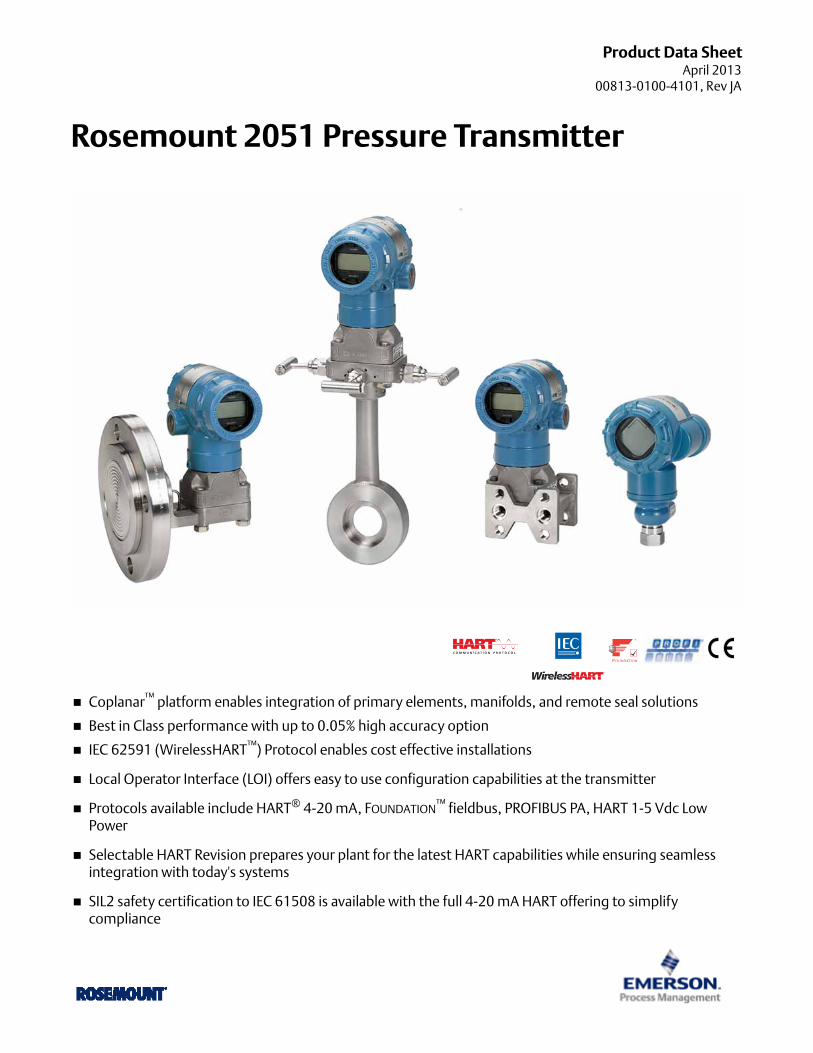
Rosemount 2051 Pressure Transmitter
Coplanar™ platform enables integration of primary elements, manifolds, and remote seal solutions
Best in Class performance with up to 0.05% high accuracy option
IEC 62591 (WirelessHART™) Protocol enables cost effective installations
Local Operator Interface (LOI) offers easy to use configuration capabilities at the transmitter
Protocols available include HART® 4-20 mA, FOUNDATION™ fieldbus, PROFIBUS PA, HART 1-5 Vdc Low Power
Selectable HART Revision prepares your plant for the latest HART capabilities while ensuring seamless integration with today's systems
SIL2 safety certification to IEC 61508 is available with the full 4-20 mA HART offering to simplify compliance

Rosemount 2051 April 2013
Rosemount 2051 Pressure Transmitter Product OfferingFOUNDATION of reliable measurement
Differential, gage, and absolute pressure measurement
Select from an extensive offering of DP Flowmeters, Liquid Level, Manifolds and Flanges.
Available with variety of protocols and materials.
Industry leading capabilities extended to IEC 62591 (WirelessHART)
Cost effectively implement wireless on the industry's most proven platform
Optimize safety with the industry's only intrinsically safe Power Module
Eliminate wiring design and construction complexities to lower costs by 40-60%
Quickly deploy new pressure, level and flow measurements in 70% less time
Innovative, integrated DP Flowmeters
Fully assembled and leak tested for out-of-the-box installation
Reduce straight pipe requirements, lower permanent pressure loss, and achieve accurate measurement in small line sizes
Up to 2.00% volumetric flow accuracy at 5:1 turndown
Proven, reliable, and innovative DP Level technologies
Connect to virtually any process with a comprehensive offering of process connections, fill fluids, direct mount or capillary connections and materials
Quantify and optimize total system performance with QZ option
Optimize level measurement with cost efficient Tuned-System Assemblies
Instrument manifolds – quality, convenient, and easy
Designed and engineered for optimal performance with Rosemount transmitters
Save installation time and money with factory assembly
Offers a variety of styles, materials, and configurations
Table of Contents
Rosemount 2051C Coplanar Pressure Transmitter . 3
Rosemount 2051T In-Line Pressure Transmitter . . . 12
Rosemount 2051CF Flowmeters . . . . . . . . . . . . . . . . 19
Rosemount 2051L Liquid Level Transmitter . . . . . . . 42
Specifications . . . . . . . . . . . . . . . . . . . . . . . . . . . . . . . .50
Product certifications . . . . . . . . . . . . . . . . . . . . . . . . .60
Dimensional drawings . . . . . . . . . . . . . . . . . . . . . . . . .68
2 www.rosemount.com

Rosemount 2051April 2013
Rosemount 2051C Coplanar Pressure Transmitter
Additional InformationSpecifications: page 50Certifications: page 60Dimensional Drawings: page 68
Configuration Transmitter Output Code
4-20 mA HART®
20512051 with Selectable HART(1)
(1) The 4-20mA with Selectable HART device can be ordered with Transmitter Output option code A plus any of the following options codes: M4, QT, DZ, CR, CS, CT, HR5, HR7.
A
Lower Power20512051 with Selectable HART(1)
M
FOUNDATION Fieldbus FProfibus WWireless X
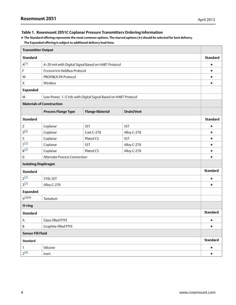
Table 1. Rosemount 2051C Coplanar Pressure Transmitters Ordering Information★ The Standard offering represents the most common options. The starred options (★) should be selected for best delivery.
__The Expanded offering is subject to additional delivery lead time.
Model Transmitter type
2051C Coplanar Pressure Transmitter
Measurement Type
Standard Standard
D Differential ★
G Gage ★
Pressure Range
Standard Standard
2051CD 2051CG
1-25 to 25 inH2O (-62.2 to 62.2 mbar)
-25 to 25 inH2O (-62.2 to 62.2 mbar)★
2-250 to 250 inH2O (-623 to 623 mbar)
-250 to 250 inH2O (-623 to 623 mbar)★
3-1000 to 1000 inH2O (-2.5 to 2.5 bar)
-393 to 1000 inH2O (-0.98 to 2.5 bar)★
4 -300 to 300 psi (-20.7 to 20.7 bar) -14.2 to 300 psi (-0.98 to 20.7 bar) ★
5-2000 to 2000 psi (-137.9 to 137.9 bar)
-14.2 to 2000 psi (-0.98 to 137.9 bar)★
2051C Coplanar Pressure Transmitter
3www.rosemount.com
Rosemount 2051 April 2013
Transmitter Output
Standard Standard
A(1) 4–20 mA with Digital Signal Based on HART Protocol ★
F FOUNDATION fieldbus Protocol ★
W PROFIBUS PA Protocol ★
X Wireless ★
Expanded
M Low-Power, 1–5 Vdc with Digital Signal Based on HART Protocol
Materials of Construction
Process Flange Type Flange Material Drain/Vent
Standard Standard
2 Coplanar SST SST ★
3(2) Coplanar Cast C-276 Alloy C-276 ★
5 Coplanar Plated CS SST ★
7(2) Coplanar SST Alloy C-276 ★
8(2) Coplanar Plated CS Alloy C-276 ★
0 Alternate Process Connection ★
Isolating Diaphragm
Standard Standard
2(2) 316L SST ★
3(2) Alloy C-276 ★
Expanded
5(3)(4) Tantalum
O-ring
Standard Standard
A Glass-filled PTFE ★
B Graphite-filled PTFE ★
Sensor Fill Fluid
Standard Standard
1 Silicone ★
2(4) Inert ★
Table 1. Rosemount 2051C Coplanar Pressure Transmitters Ordering Information★ The Standard offering represents the most common options. The starred options (★) should be selected for best delivery.
__The Expanded offering is subject to additional delivery lead time.
4 www.rosemount.com
Rosemount 2051April 2013
5www.rosemount.com
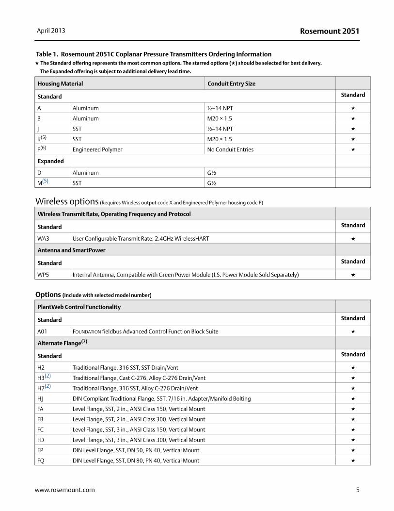
Housing Material Conduit Entry Size
Standard Standard
A Aluminum ½–14 NPT ★
B Aluminum M20 × 1.5 ★
J SST ½–14 NPT ★
K(5) SST M20 × 1.5 ★
P(6) Engineered Polymer No Conduit Entries ★
Expanded
D Aluminum G½
M(5) SST G½
Wireless options (Requires Wireless output code X and Engineered Polymer housing code P)
Wireless Transmit Rate, Operating Frequency and Protocol
Standard Standard
WA3 User Configurable Transmit Rate, 2.4GHz WirelessHART ★
Antenna and SmartPower
Standard Standard
WP5 Internal Antenna, Compatible with Green Power Module (I.S. Power Module Sold Separately) ★
Options (Include with selected model number)
PlantWeb Control Functionality
Standard Standard
A01 FOUNDATION fieldbus Advanced Control Function Block Suite ★
Alternate Flange(7)
Standard Standard
H2 Traditional Flange, 316 SST, SST Drain/Vent ★
H3(2) Traditional Flange, Cast C-276, Alloy C-276 Drain/Vent ★
H7(2) Traditional Flange, 316 SST, Alloy C-276 Drain/Vent ★
HJ DIN Compliant Traditional Flange, SST, 7/16 in. Adapter/Manifold Bolting ★
FA Level Flange, SST, 2 in., ANSI Class 150, Vertical Mount ★
FB Level Flange, SST, 2 in., ANSI Class 300, Vertical Mount ★
FC Level Flange, SST, 3 in., ANSI Class 150, Vertical Mount ★
FD Level Flange, SST, 3 in., ANSI Class 300, Vertical Mount ★
FP DIN Level Flange, SST, DN 50, PN 40, Vertical Mount ★
FQ DIN Level Flange, SST, DN 80, PN 40, Vertical Mount ★
Table 1. Rosemount 2051C Coplanar Pressure Transmitters Ordering Information★ The Standard offering represents the most common options. The starred options (★) should be selected for best delivery.
__The Expanded offering is subject to additional delivery lead time.
Rosemount 2051 April 2013
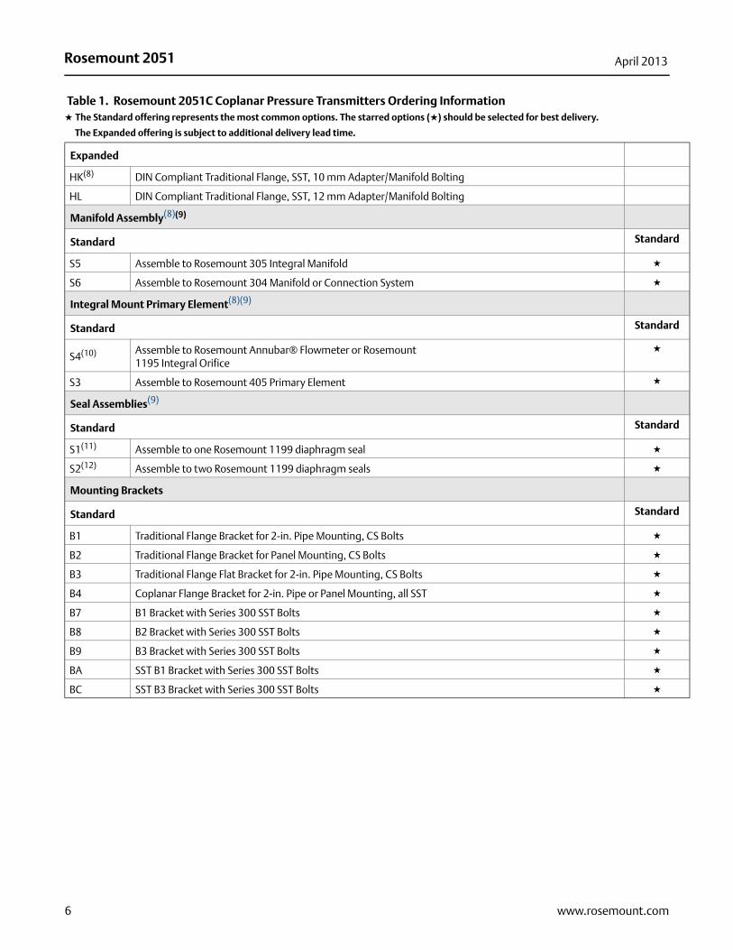
Expanded
HK(8) DIN Compliant Traditional Flange, SST, 10 mm Adapter/Manifold Bolting
HL DIN Compliant Traditional Flange, SST, 12 mm Adapter/Manifold Bolting
Manifold Assembly(8)(9)
Standard Standard
S5 Assemble to Rosemount 305 Integral Manifold ★
S6 Assemble to Rosemount 304 Manifold or Connection System ★
Integral Mount Primary Element(8)(9)
Standard Standard
S4(10) Assemble to Rosemount Annubar® Flowmeter or Rosemount 1195 Integral Orifice
★
S3 Assemble to Rosemount 405 Primary Element ★
Seal Assemblies(9)
Standard Standard
S1(11) Assemble to one Rosemount 1199 diaphragm seal ★
S2(12) Assemble to two Rosemount 1199 diaphragm seals ★
Mounting Brackets
Standard Standard
B1 Traditional Flange Bracket for 2-in. Pipe Mounting, CS Bolts ★
B2 Traditional Flange Bracket for Panel Mounting, CS Bolts ★
B3 Traditional Flange Flat Bracket for 2-in. Pipe Mounting, CS Bolts ★
B4 Coplanar Flange Bracket for 2-in. Pipe or Panel Mounting, all SST ★
B7 B1 Bracket with Series 300 SST Bolts ★
B8 B2 Bracket with Series 300 SST Bolts ★
B9 B3 Bracket with Series 300 SST Bolts ★
BA SST B1 Bracket with Series 300 SST Bolts ★
BC SST B3 Bracket with Series 300 SST Bolts ★
Table 1. Rosemount 2051C Coplanar Pressure Transmitters Ordering Information★ The Standard offering represents the most common options. The starred options (★) should be selected for best delivery.
__The Expanded offering is subject to additional delivery lead time.
6 www.rosemount.com
Rosemount 2051April 2013
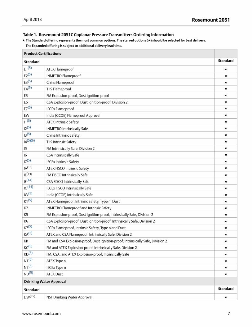
Product Certifications
Standard Standard
E1(5) ATEX Flameproof ★
E2(5) INMETRO Flameproof ★
E3(5) China Flameproof ★
E4(5) TIIS Flameproof ★
E5 FM Explosion-proof, Dust Ignition-proof ★
E6 CSA Explosion-proof, Dust Ignition-proof, Division 2 ★
E7(5) IECEx Flameproof ★
EW India (CCOE) Flameproof Approval ★
I1(5) ATEX Intrinsic Safety ★
I2(5) INMETRO Intrinsically Safe ★
I3(5) China Intrinsic Safety ★
I4(5)(6) TIIS Intrinsic Safety ★
I5 FM Intrinsically Safe, Division 2 ★
I6 CSA Intrinsically Safe ★
I7(5) IECEx Intrinsic Safety ★
IA(13) ATEX FISCO Intrinsic Safety ★
IE(14) FM FISCO Intrinsically Safe ★
IF(14) CSA FISCO Intrinsically Safe ★
IG(14) IECEx FISCO Intrinsically Safe ★
IW(5) India (CCOE) Intrinsically Safe ★
K1(5) ATEX Flameproof, Intrinsic Safety, Type n, Dust ★
K2 INMETRO Flameproof and Intrinsic Safety ★
K5 FM Explosion-proof, Dust Ignition-proof, Intrinsically Safe, Division 2 ★
K6 CSA Explosion-proof, Dust Ignition-proof, Intrinsically Safe, Division 2 ★
K7(5) IECEx Flameproof, Intrinsic Safety, Type n and Dust ★
KA(5) ATEX and CSA Flameproof, Intrinsically Safe, Division 2 ★
KB FM and CSA Explosion-proof, Dust Ignition-proof, Intrinsically Safe, Division 2 ★
KC(5) FM and ATEX Explosion-proof, Intrinsically Safe, Division 2 ★
KD(5) FM, CSA, and ATEX Explosion-proof, Intrinsically Safe ★
N1(5) ATEX Type n ★
N7(5) IECEx Type n ★
ND(5) ATEX Dust ★
Drinking Water Approval
Standard Standard
DW(15) NSF Drinking Water Approval ★
Table 1. Rosemount 2051C Coplanar Pressure Transmitters Ordering Information★ The Standard offering represents the most common options. The starred options (★) should be selected for best delivery.
__The Expanded offering is subject to additional delivery lead time.
7www.rosemount.com
Rosemount 2051 April 2013
8 www.rosemount.com
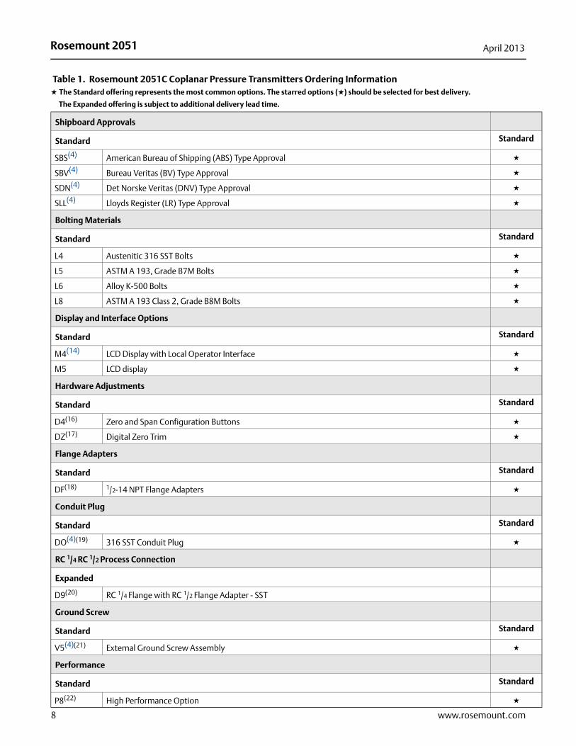
Shipboard Approvals
Standard Standard
SBS(4) American Bureau of Shipping (ABS) Type Approval ★
SBV(4) Bureau Veritas (BV) Type Approval ★
SDN(4) Det Norske Veritas (DNV) Type Approval ★
SLL(4) Lloyds Register (LR) Type Approval ★
Bolting Materials
Standard Standard
L4 Austenitic 316 SST Bolts ★
L5 ASTM A 193, Grade B7M Bolts ★
L6 Alloy K-500 Bolts ★
L8 ASTM A 193 Class 2, Grade B8M Bolts ★
Display and Interface Options
Standard Standard
M4(14) LCD Display with Local Operator Interface ★
M5 LCD display ★
Hardware Adjustments
Standard Standard
D4(16) Zero and Span Configuration Buttons ★
DZ(17) Digital Zero Trim ★
Flange Adapters
Standard Standard
DF(18) 1/2-14 NPT Flange Adapters ★
Conduit Plug
Standard Standard
DO(4)(19) 316 SST Conduit Plug ★
RC 1/4 RC 1/2 Process Connection
Expanded
D9(20) RC 1/4 Flange with RC 1/2 Flange Adapter - SST
Ground Screw
Standard Standard
V5(4)(21) External Ground Screw Assembly ★
Performance
Standard Standard
P8(22) High Performance Option ★
Table 1. Rosemount 2051C Coplanar Pressure Transmitters Ordering Information★ The Standard offering represents the most common options. The starred options (★) should be selected for best delivery.
__The Expanded offering is subject to additional delivery lead time.
Rosemount 2051April 2013
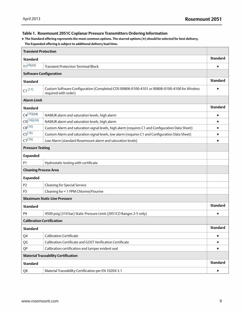
Transient Protection
Standard Standard
T1(4)(23) Transient Protection Terminal Block ★
Software Configuration
Standard Standard
C1 (17) Custom Software Configuration (Completed CDS 00806-0100-4101 or 00806-0100-4100 for Wireless required with order)
★
Alarm Limit
Standard Standard
C4(16)(24) NAMUR alarm and saturation levels, high alarm ★
CN(16)(24) NAMUR alarm and saturation levels, high alarm ★
CR(16) Custom Alarm and saturation signal levels, high alarm (requires C1 and Configuration Data Sheet) ★
CS(16) Custom Alarm and saturation signal levels, low alarm (requires C1 and Configuration Data Sheet) ★
CT(16) Low Alarm (standard Rosemount alarm and saturation levels) ★
Pressure Testing
Expanded
P1 Hydrostatic testing with certificate
Cleaning Process Area
Expanded
P2 Cleaning for Special Service
P3 Cleaning for < 1 PPM Chlorine/Flourine
Maximum Static Line Pressure
Standard Standard
P9 4500 psig (310 bar) Static Pressure Limit (2051CD Ranges 2-5 only) ★
Calibration Certification
Standard Standard
Q4 Calibration Certificate ★
QG Calibration Certificate and GOST Verification Certificate ★
QP Calibration certification and tamper evident seal ★
Material Traceability Certification
Standard Standard
Q8 Material Traceability Certification per EN 10204 3.1 ★
Table 1. Rosemount 2051C Coplanar Pressure Transmitters Ordering Information★ The Standard offering represents the most common options. The starred options (★) should be selected for best delivery.
__The Expanded offering is subject to additional delivery lead time.
9www.rosemount.com
Rosemount 2051 April 2013
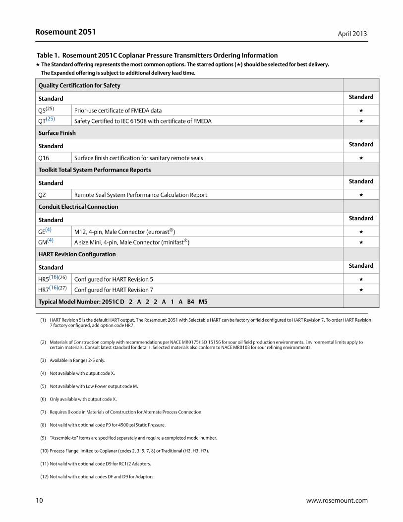
Quality Certification for Safety
Standard Standard
QS(25) Prior-use certificate of FMEDA data ★
QT(25) Safety Certified to IEC 61508 with certificate of FMEDA ★
Surface Finish
Standard Standard
Q16 Surface finish certification for sanitary remote seals ★
Toolkit Total System Performance Reports
Standard Standard
QZ Remote Seal System Performance Calculation Report ★
Conduit Electrical Connection
Standard Standard
GE(4) M12, 4-pin, Male Connector (eurorast®) ★
GM(4) A size Mini, 4-pin, Male Connector (minifast®) ★
HART Revision Configuration
Standard Standard
HR5(16)(26) Configured for HART Revision 5 ★
HR7(16)(27) Configured for HART Revision 7 ★
Typical Model Number: 2051C D 2 A 2 2 A 1 A B4 M5
(1) HART Revision 5 is the default HART output. The Rosemount 2051 with Selectable HART can be factory or field configured to HART Revision 7. To order HART Revision 7 factory configured, add option code HR7.
(2) Materials of Construction comply with recommendations per NACE MR0175/ISO 15156 for sour oil field production environments. Environmental limits apply to certain materials. Consult latest standard for details. Selected materials also conform to NACE MR0103 for sour refining environments.
(3) Available in Ranges 2-5 only.
(4) Not available with output code X.
(5) Not available with Low Power output code M.
(6) Only available with output code X.
(7) Requires 0 code in Materials of Construction for Alternate Process Connection.
(8) Not valid with optional code P9 for 4500 psi Static Pressure.
(9) “Assemble-to” items are specified separately and require a completed model number.
(10) Process Flange limited to Coplanar (codes 2, 3, 5, 7, 8) or Traditional (H2, H3, H7).
(11) Not valid with optional code D9 for RC1/2 Adaptors.
(12) Not valid with optional codes DF and D9 for Adaptors.
Table 1. Rosemount 2051C Coplanar Pressure Transmitters Ordering Information★ The Standard offering represents the most common options. The starred options (★) should be selected for best delivery.
__The Expanded offering is subject to additional delivery lead time.
10 www.rosemount.com
Rosemount 2051April 2013
(13) Only valid with FOUNDATION fieldbus output code F.
(14) Not available with FOUNDATION fieldbus output code F and Wireless Output Code X.
(15) Not available with Alloy C-276 isolator (3 code), tantalum isolator (5 code), all cast C-276 flanges, all plated CS flanges, all DIN flanges, all Level flanges, assemble-to
manifolds (S5 and S6 codes), assemble-to seals (S1 and S2 codes), assemble-to primary elements (S3 and S4 codes), surface finish certification (Q16 code), and remote
seal system report (QZ code).
(16) Only Available with HART 4-20 mA (output codes A and M).
(17) Only available with HART 4-20 mA Output (Output Codes A and M) and Wireless Output (Output Code X).
(18) Not valid with Alternate Process Connection options S3, S4, S5, S6.
(19) Transmitter is shipped with 316 SST conduit plug (uninstalled) in place of standard carbon steel conduit plug.
(20) Not available with Alternate Process Connection: DIN Flanges and Level Flanges.
(21) The V5 option is not needed with the T1 option; external ground screw assembly is included with the T1 option.
(22) Available with 4-20 mA HART output code A, Wireless output code X, FOUNDATION fieldbus output code F, 2051C Ranges 2-5 or 2051T Ranges 1-4, SST diaphragms and
silicone fill fluid. High Performance Option includes 0.05% Reference Accuracy, 5 year stability and improved ambient temperature effect specifications. See
Performance specifications for details.
(23) The T1 option is not needed with FISCO Product Certifications; transient protection is included in the FISCO product certification codes IA and IE.
(24) NAMUR-Compliant operation is pre-set at the factory and cannot be changed to standard operation in the field.
(25) Only available with HART 4-20 mA output (output code A).
(26) Configures the HART output to HART Revision 5. The device can be field configured to HART Revision 7 if needed.
(27) Configures the HART output to HART Revision 7. The device can be field configured to HART Revision 5 if needed.
11www.rosemount.com
Rosemount 2051 April 2013
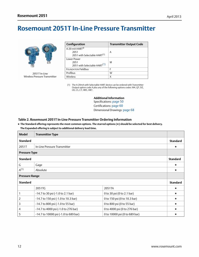
Rosemount 2051T In-Line Pressure Transmitter
Additional InformationSpecifications: page 50Certifications: page 60Dimensional Drawings: page 68
20 Ordering Information
Configuration Transmitter Output Code
4-20 mA HART®
20512051 with Selectable HART(1)
(1) The 4-20mA with Selectable HART device can be ordered with Transmitter Output option code A plus any of the following options codes: M4, QT, DZ, CR, CS, CT, HR5, HR7.
A
Lower Power20512051 with Selectable HART(1)
M
FOUNDATION Fieldbus FProfibus WWireless X
2051T In-Line Wireless Pressure Transmitter
Table 2. Rosemount 2051T In-Line Pressure Transmitter Ordering Information★ The Standard offering represents the most common options. The starred options (★) should be selected for best delivery.
__The Expanded offering is subject to additional delivery lead time.
Model Transmitter Type
Standard Standard
2051T In-Line Pressure Transmitter ★
Pressure Type
Standard Standard
G Gage ★
A(1) Absolute ★
Pressure Range
Standard Standard
2051TG 2051TA ★
1 -14.7 to 30 psi (-1.0 to 2.1 bar) 0 to 30 psi (0 to 2.1 bar) ★
2 -14.7 to 150 psi (-1.0 to 10.3 bar) 0 to 150 psi (0 to 10.3 bar) ★
3 -14.7 to 800 psi (-1.0 to 55 bar) 0 to 800 psi (0 to 55 bar) ★
4 -14.7 to 4000 psi (-1.0 to 276 bar) 0 to 4000 psi (0 to 276 bar) ★
5 -14.7 to 10000 psi (-1.0 to 689 bar) 0 to 10000 psi (0 to 689 bar) ★
12 www.rosemount.com
Rosemount 2051April 2013
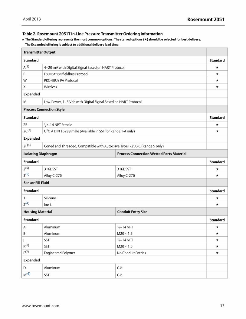
Transmitter Output
Standard Standard
A(2) 4–20 mA with Digital Signal Based on HART Protocol ★
F FOUNDATION fieldbus Protocol ★
W PROFIBUS PA Protocol ★
X Wireless ★
Expanded
M Low-Power, 1–5 Vdc with Digital Signal Based on HART Protocol
Process Connection Style
Standard Standard
2B 1/2–14 NPT female ★
2C(3) G1/2 A DIN 16288 male (Available in SST for Range 1-4 only) ★
Expanded
2F(4) Coned and Threaded, Compatible with Autoclave Type F-250-C (Range 5 only)
Isolating Diaphragm Process Connection Wetted Parts Material
Standard Standard
2(5) 316L SST 316L SST ★
3(5) Alloy C-276 Alloy C-276 ★
Sensor Fill Fluid
Standard Standard
1 Silicone ★
2(4) Inert ★
Housing Material Conduit Entry Size
Standard Standard
A Aluminum ½–14 NPT ★
B Aluminum M20 × 1.5 ★
J SST ½–14 NPT ★
K(6) SST M20 × 1.5 ★
P(7) Engineered Polymer No Conduit Entries ★
Expanded
D Aluminum G½
M(6) SST G½
Table 2. Rosemount 2051T In-Line Pressure Transmitter Ordering Information★ The Standard offering represents the most common options. The starred options (★) should be selected for best delivery.
__The Expanded offering is subject to additional delivery lead time.
13www.rosemount.com

Rosemount 2051 April 2013
Wireless options (Requires Wireless output code X and Engineered Polymer housing code P)
Wireless Transmit Rate, Operating Frequency and Protocol
Standard Standard
WA3 User Configurable Transmit Rate, 2.4GHz WirelessHART ★
Antenna and SmartPower
Standard Standard
WP5 Internal Antenna, Compatible with Green Power Module (I.S. Power Module Sold Separately) ★
Options (Include with selected model number)
PlantWeb Control Functionality
Standard Standard
A01 FOUNDATION fieldbus Advanced Control Function Block Suite ★★
Manifold Assemblies
Standard Standard
S5(8) Assemble to Rosemount 306 Integral Manifold ★★
Seal Assemblies
Standard Standard
S1(8) Assemble to one Rosemount 1199 diaphragm seal ★★
Mounting Bracket
Standard Standard
B4 Bracket for 2-in. Pipe or Panel Mounting, All SST ★★
Table 2. Rosemount 2051T In-Line Pressure Transmitter Ordering Information★ The Standard offering represents the most common options. The starred options (★) should be selected for best delivery.
__The Expanded offering is subject to additional delivery lead time.
14 www.rosemount.com
Rosemount 2051April 2013
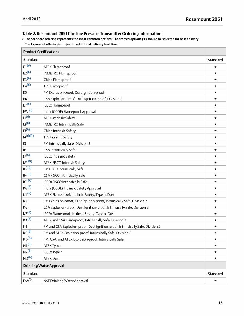
Product Certifications
Standard Standard
E1(6) ATEX Flameproof ★
E2(6) INMETRO Flameproof ★
E3(6) China Flameproof ★
E4(6) TIIS Flameproof ★
E5 FM Explosion-proof, Dust Ignition-proof ★
E6 CSA Explosion-proof, Dust Ignition-proof, Division 2 ★
E7(6) IECEx Flameproof ★
EW(6) India (CCOE) Flameproof Approval ★
I1(6) ATEX Intrinsic Safety ★
I2(6) INMETRO Intrinsically Safe ★
I3(6) China Intrinsic Safety ★
I4(6)(7) TIIS Intrinsic Safety ★
I5 FM Intrinsically Safe, Division 2 ★
I6 CSA Intrinsically Safe ★
I7(6) IECEx Intrinsic Safety ★
IA(10) ATEX FISCO Intrinsic Safety ★
IE(10) FM FISCO Intrinsically Safe ★
IF(10) CSA FISCO Intrinsically Safe ★
IG(10) IECEx FISCO Intrinsically Safe ★
IW(6) India (CCOE) Intrinsic Safety Approval ★
K1(6) ATEX Flameproof, Intrinsic Safety, Type n, Dust ★
K5 FM Explosion-proof, Dust Ignition-proof, Intrinsically Safe, Division 2 ★
K6 CSA Explosion-proof, Dust Ignition-proof, Intrinsically Safe, Division 2 ★
K7(6) IECEx Flameproof, Intrinsic Safety, Type n, Dust ★
KA(6) ATEX and CSA Flameproof, Intrinsically Safe, Division 2 ★
KB FM and CSA Explosion-proof, Dust Ignition-proof, Intrinsically Safe, Division 2 ★
KC(6) FM and ATEX Explosion-proof, Intrinsically Safe, Division 2 ★
KD(6) FM, CSA, and ATEX Explosion-proof, Intrinsically Safe ★
N1(6) ATEX Type n ★
N7(6) IECEx Type n ★
ND(6) ATEX Dust ★
Drinking Water Approval
Standard Standard
DW(9) NSF Drinking Water Approval ★
Table 2. Rosemount 2051T In-Line Pressure Transmitter Ordering Information★ The Standard offering represents the most common options. The starred options (★) should be selected for best delivery.
__The Expanded offering is subject to additional delivery lead time.
15www.rosemount.com
Rosemount 2051 April 2013
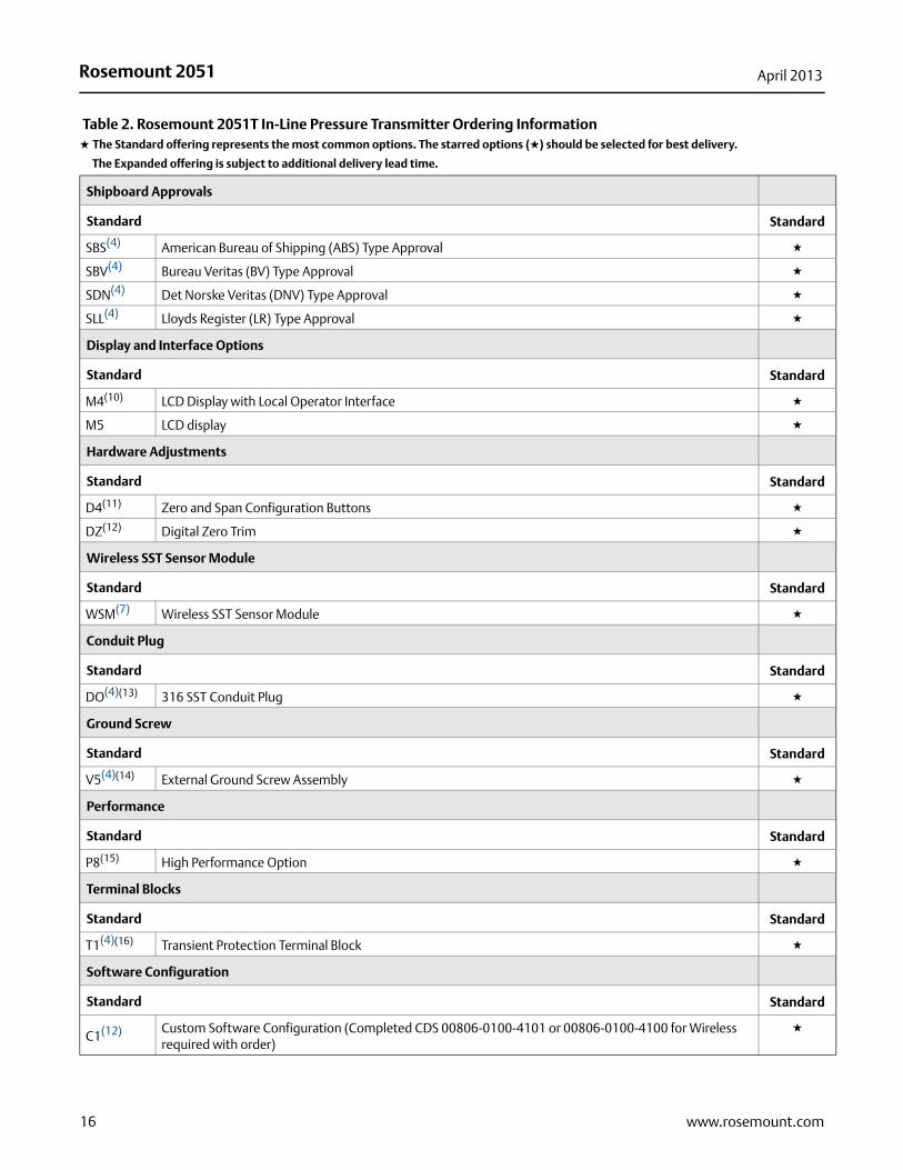
Shipboard Approvals
Standard Standard
SBS(4) American Bureau of Shipping (ABS) Type Approval ★
SBV(4) Bureau Veritas (BV) Type Approval ★
SDN(4) Det Norske Veritas (DNV) Type Approval ★
SLL(4) Lloyds Register (LR) Type Approval ★
Display and Interface Options
Standard Standard
M4(10) LCD Display with Local Operator Interface ★
M5 LCD display ★
Hardware Adjustments
Standard Standard
D4(11) Zero and Span Configuration Buttons ★
DZ(12) Digital Zero Trim ★
Wireless SST Sensor Module
Standard Standard
WSM(7) Wireless SST Sensor Module ★
Conduit Plug
Standard Standard
DO(4)(13) 316 SST Conduit Plug ★
Ground Screw
Standard Standard
V5(4)(14) External Ground Screw Assembly ★
Performance
Standard Standard
P8(15) High Performance Option ★
Terminal Blocks
Standard Standard
T1(4)(16) Transient Protection Terminal Block ★
Software Configuration
Standard Standard
C1(12) Custom Software Configuration (Completed CDS 00806-0100-4101 or 00806-0100-4100 for Wireless required with order)
★
Table 2. Rosemount 2051T In-Line Pressure Transmitter Ordering Information★ The Standard offering represents the most common options. The starred options (★) should be selected for best delivery.
__The Expanded offering is subject to additional delivery lead time.
16 www.rosemount.com
Rosemount 2051April 2013
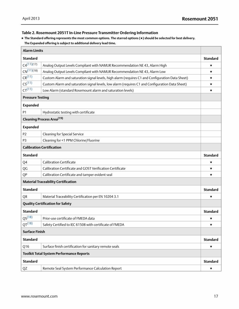
Alarm Limits
Standard Standard
C4(11)(17) Analog Output Levels Compliant with NAMUR Recommendation NE 43, Alarm High ★
CN(11)(18) Analog Output Levels Compliant with NAMUR Recommendation NE 43, Alarm Low ★
CR(11) Custom Alarm and saturation signal levels, high alarm (requires C1 and Configuration Data Sheet) ★
CS(11) Custom Alarm and saturation signal levels, low alarm (requires C1 and Configuration Data Sheet) ★
CT(11) Low Alarm (standard Rosemount alarm and saturation levels) ★
Pressure Testing
Expanded
P1 Hydrostatic testing with certificate
Cleaning Process Area(19)
Expanded
P2 Cleaning for Special Service
P3 Cleaning for <1 PPM Chlorine/Fluorine
Calibration Certification
Standard Standard
Q4 Calibration Certificate ★
QG Calibration Certificate and GOST Verification Certificate ★
QP Calibration Certificate and tamper evident seal ★
Material Traceability Certification
Standard Standard
Q8 Material Traceability Certification per EN 10204 3.1 ★
Quality Certification for Safety
Standard Standard
QS(18) Prior-use certificate of FMEDA data ★
QT(18) Safety Certified to IEC 61508 with certificate of FMEDA ★
Surface Finish
Standard Standard
Q16 Surface finish certification for sanitary remote seals ★
Toolkit Total System Performance Reports
Standard Standard
QZ Remote Seal System Performance Calculation Report ★
Table 2. Rosemount 2051T In-Line Pressure Transmitter Ordering Information★ The Standard offering represents the most common options. The starred options (★) should be selected for best delivery.
__The Expanded offering is subject to additional delivery lead time.
17www.rosemount.com
Rosemount 2051 April 2013
18 www.rosemount.com
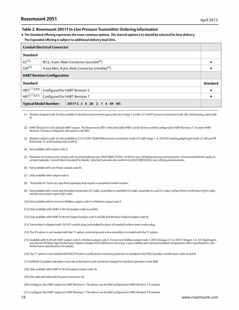
Conduit Electrical Connector
Standard Standard
GE(4) M12, 4-pin, Male Connector (eurofast®) ★
GM(4) A size Mini, 4-pin, Male Connector (minifast®) ★
HART Revision Configuration
Standard Standard
HR5(11)(20) Configured for HART Revision 5 ★
HR7(11)(21) Configured for HART Revision 7 ★
Typical Model Number: 2051T G 3 A 2B 2 1 A B4 M5
(1) Wireless Output (code X) only available in absolute measurement type (code A) in range 1-5 with 1/2 14 NPT process connection (code 2B), and housing code (code P)
(2) HART Revision 5 is the default HART output. The Rosemount 2051 with Selectable HART can be factory or field configured to HART Revision 7. To order HART Revision 7 factory configured, add option code HR7.
(3) Wireless output (code X) only available in G1/2 A DIN 16288 Male process connection (code 2C) with range 1-4, 316 SST isolating diaphragm (code 2), silicone fill fluid (code 1), and housing code (code P).
(4) Not available with output code X.
(5) Materials of Construction comply with recommendations per NACE MR0175/ISO 15156 for sour oil field production environments. Environmental limits apply to certain materials. Consult latest standard for details. Selected materials also conform to NACE MR0103 for sour refining environments.
(6) Not available with Low Power output code M.
(7) Only available with output code X.
(8) “Assemble-to” items are specified separately and require a completed model number.
(9) Not available with coned and threaded connection (2F code), assemble-to manifold (S5 code), assemble-to seal (S1 code), surface finish certification (Q16 code), remote seal system report (QZ code).
(10) Not available with FOUNDATION fieldbus output code F or Wireless output code X
(11) Only Available with HART 4-20 mA (output codes A and M).
(12) Only available with HART 4-20 mA Output (output code A and M) and Wireless Output (output code X).
(13) Transmitter is shipped with 316 SST conduit plug (uninstalled) in place of standard carbon steel conduit plug.
(14) The V5 option is not needed with the T1 option; external ground screw assembly is included with the T1 option.
(15) Available with 4-20 mA HART output code A, Wireless output code X, FOUNDATION fieldbus output code F, 2051C Ranges 2-5 or 2051T Ranges 1-4, SST diaphragms and silicone fill fluid. High Performance Option includes 0.05% Reference Accuracy, 5 year stability and improved ambient temperature effect specifications. See Performance Specifications for details.
(16) The T1 option is not needed with FISCO Product Certifications; transient protection is included in the FISCO product certification codes IA and IE.
(17) NAMUR-Compliant operation is pre-set at the factory and cannot be changed to standard operation in the field.
(18) Only available with HART 4-20 mA output (output code A).
(19) Not valid with Alternate Process Connection S5.
(20) Configures the HART output to HART Revision 5. The device can be field configured to HART Revision 7 if needed.
(21) Configures the HART output to HART Revision 7. The device can be field configured to HART Revision 5 if needed.
Table 2. Rosemount 2051T In-Line Pressure Transmitter Ordering Information★ The Standard offering represents the most common options. The starred options (★) should be selected for best delivery.
__The Expanded offering is subject to additional delivery lead time.
Rosemount 2051April 2013
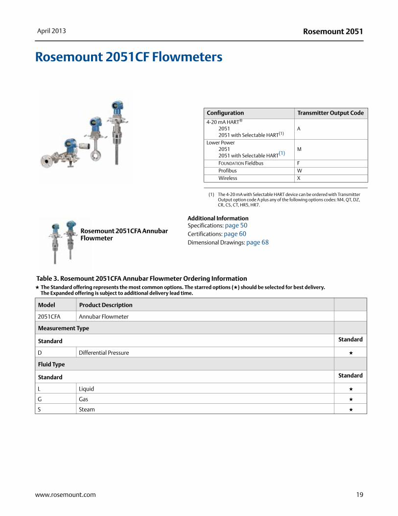
Rosemount 2051CF Flowmeters
Additional InformationSpecifications: page 50Certifications: page 60Dimensional Drawings: page 68
Configuration Transmitter Output Code
4-20 mA HART®
20512051 with Selectable HART(1)
(1) The 4-20 mA with Selectable HART device can be ordered with Transmitter Output option code A plus any of the following options codes: M4, QT, DZ, CR, CS, CT, HR5, HR7.
A
Lower Power20512051 with Selectable HART(1)
M
FOUNDATION Fieldbus FProfibus WWireless X
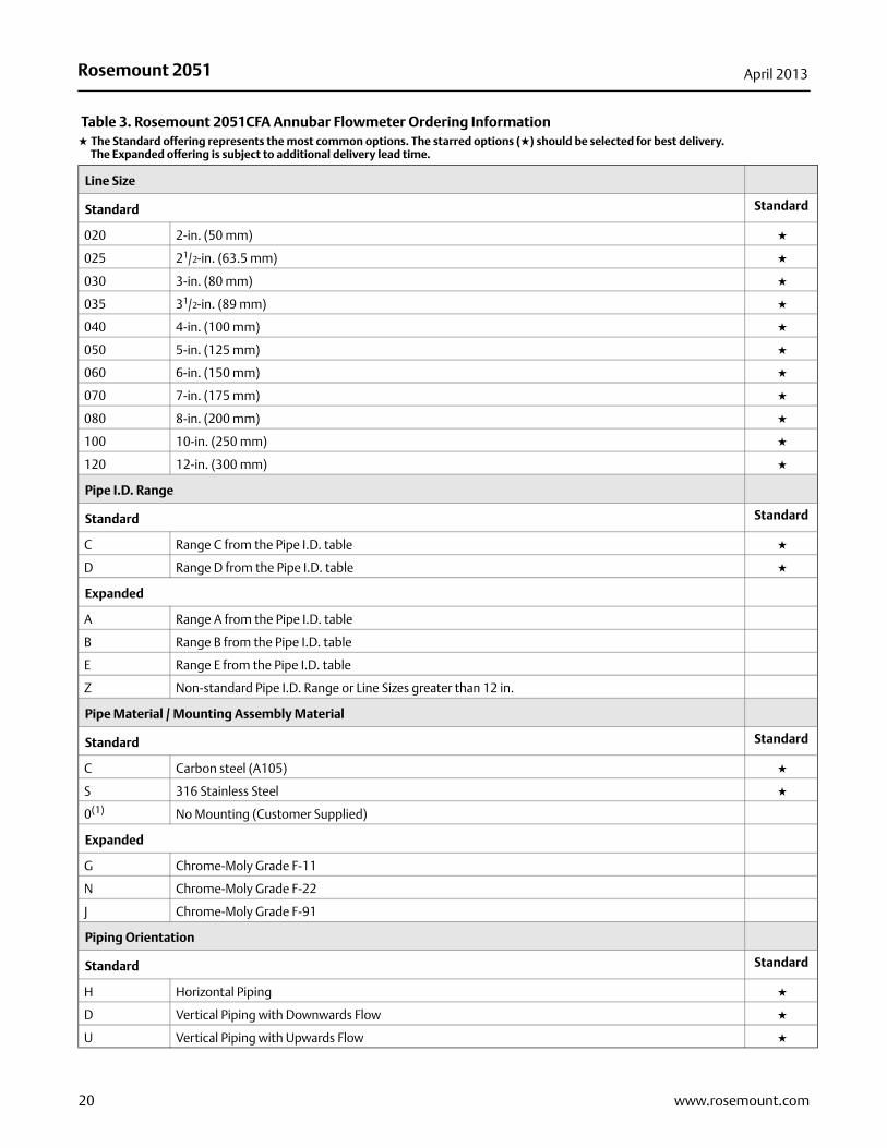
Table 3. Rosemount 2051CFA Annubar Flowmeter Ordering Information★ The Standard offering represents the most common options. The starred options (★) should be selected for best delivery.__The Expanded offering is subject to additional delivery lead time.
Model Product Description
2051CFA Annubar Flowmeter
Measurement Type
Standard Standard
D Differential Pressure ★
Fluid Type
Standard Standard
L Liquid ★
G Gas ★
S Steam ★
Rosemount 2051CFA Annubar Flowmeter
19www.rosemount.com
Rosemount 2051 April 2013
Line Size
Standard Standard
020 2-in. (50 mm) ★
025 21/2-in. (63.5 mm) ★
030 3-in. (80 mm) ★
035 31/2-in. (89 mm) ★
040 4-in. (100 mm) ★
050 5-in. (125 mm) ★
060 6-in. (150 mm) ★
070 7-in. (175 mm) ★
080 8-in. (200 mm) ★
100 10-in. (250 mm) ★
120 12-in. (300 mm) ★
Pipe I.D. Range
Standard Standard
C Range C from the Pipe I.D. table ★
D Range D from the Pipe I.D. table ★
Expanded
A Range A from the Pipe I.D. table
B Range B from the Pipe I.D. table
E Range E from the Pipe I.D. table
Z Non-standard Pipe I.D. Range or Line Sizes greater than 12 in.
Pipe Material / Mounting Assembly Material
Standard Standard
C Carbon steel (A105) ★
S 316 Stainless Steel ★
0(1) No Mounting (Customer Supplied)
Expanded
G Chrome-Moly Grade F-11
N Chrome-Moly Grade F-22
J Chrome-Moly Grade F-91
Piping Orientation
Standard Standard
H Horizontal Piping ★
D Vertical Piping with Downwards Flow ★
U Vertical Piping with Upwards Flow ★
Table 3. Rosemount 2051CFA Annubar Flowmeter Ordering Information★ The Standard offering represents the most common options. The starred options (★) should be selected for best delivery.__The Expanded offering is subject to additional delivery lead time.
20 www.rosemount.com
Rosemount 2051April 2013
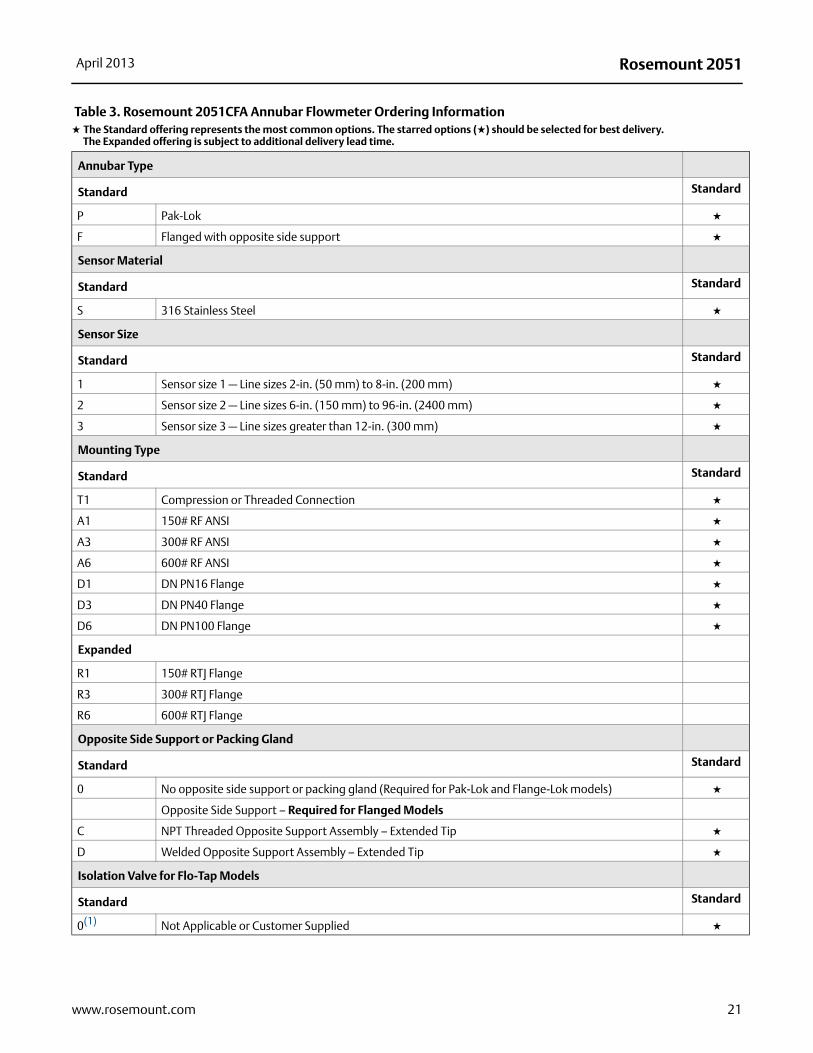
Annubar Type
Standard Standard
P Pak-Lok ★
F Flanged with opposite side support ★
Sensor Material
Standard Standard
S 316 Stainless Steel ★
Sensor Size
Standard Standard
1 Sensor size 1 — Line sizes 2-in. (50 mm) to 8-in. (200 mm) ★
2 Sensor size 2 — Line sizes 6-in. (150 mm) to 96-in. (2400 mm) ★
3 Sensor size 3 — Line sizes greater than 12-in. (300 mm) ★
Mounting Type
Standard Standard
T1 Compression or Threaded Connection ★
A1 150# RF ANSI ★
A3 300# RF ANSI ★
A6 600# RF ANSI ★
D1 DN PN16 Flange ★
D3 DN PN40 Flange ★
D6 DN PN100 Flange ★
Expanded
R1 150# RTJ Flange
R3 300# RTJ Flange
R6 600# RTJ Flange
Opposite Side Support or Packing Gland
Standard Standard
0 No opposite side support or packing gland (Required for Pak-Lok and Flange-Lok models) ★
Opposite Side Support – Required for Flanged Models
C NPT Threaded Opposite Support Assembly – Extended Tip ★
D Welded Opposite Support Assembly – Extended Tip ★
Isolation Valve for Flo-Tap Models
Standard Standard
0(1) Not Applicable or Customer Supplied ★
Table 3. Rosemount 2051CFA Annubar Flowmeter Ordering Information★ The Standard offering represents the most common options. The starred options (★) should be selected for best delivery.__The Expanded offering is subject to additional delivery lead time.
21www.rosemount.com
Rosemount 2051 April 2013
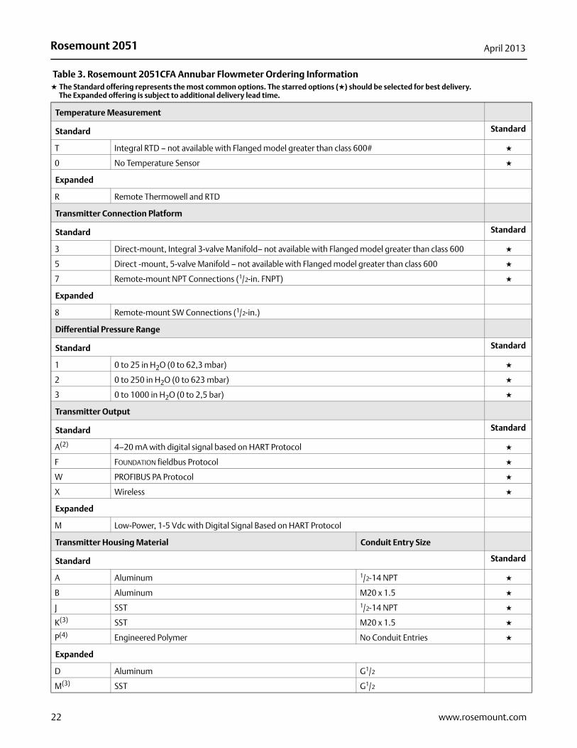
Temperature Measurement
Standard Standard
T Integral RTD – not available with Flanged model greater than class 600# ★
0 No Temperature Sensor ★
Expanded
R Remote Thermowell and RTD
Transmitter Connection Platform
Standard Standard
3 Direct-mount, Integral 3-valve Manifold– not available with Flanged model greater than class 600 ★
5 Direct -mount, 5-valve Manifold – not available with Flanged model greater than class 600 ★
7 Remote-mount NPT Connections (1/2-in. FNPT) ★
Expanded
8 Remote-mount SW Connections (1/2-in.)
Differential Pressure Range
Standard Standard
1 0 to 25 in H2O (0 to 62,3 mbar) ★
2 0 to 250 in H2O (0 to 623 mbar) ★
3 0 to 1000 in H2O (0 to 2,5 bar) ★
Transmitter Output
Standard Standard
A(2) 4–20 mA with digital signal based on HART Protocol ★
F FOUNDATION fieldbus Protocol ★
W PROFIBUS PA Protocol ★
X Wireless ★
Expanded
M Low-Power, 1-5 Vdc with Digital Signal Based on HART Protocol
Transmitter Housing Material Conduit Entry Size
Standard Standard
A Aluminum 1/2-14 NPT ★
B Aluminum M20 x 1.5 ★
J SST 1/2-14 NPT ★
K(3) SST M20 x 1.5 ★
P(4) Engineered Polymer No Conduit Entries ★
Expanded
D Aluminum G1/2
M(3) SST G1/2
Table 3. Rosemount 2051CFA Annubar Flowmeter Ordering Information★ The Standard offering represents the most common options. The starred options (★) should be selected for best delivery.__The Expanded offering is subject to additional delivery lead time.
22 www.rosemount.com
Rosemount 2051April 2013
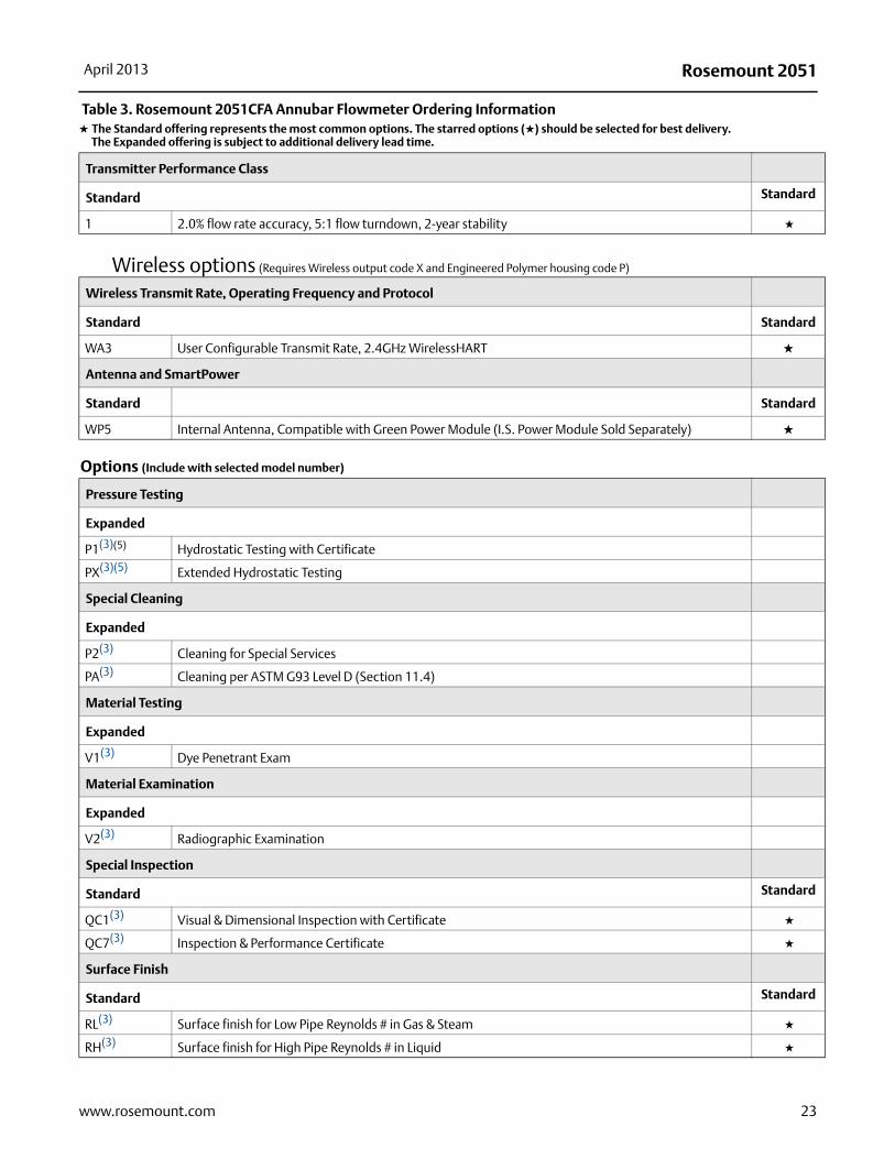
Transmitter Performance Class
Standard Standard
1 2.0% flow rate accuracy, 5:1 flow turndown, 2-year stability ★
Wireless options (Requires Wireless output code X and Engineered Polymer housing code P)
Wireless Transmit Rate, Operating Frequency and Protocol
Standard Standard
WA3 User Configurable Transmit Rate, 2.4GHz WirelessHART ★
Antenna and SmartPower
Standard Standard
WP5 Internal Antenna, Compatible with Green Power Module (I.S. Power Module Sold Separately) ★
Options (Include with selected model number)
Pressure Testing
Expanded
P1(3)(5) Hydrostatic Testing with Certificate
PX(3)(5) Extended Hydrostatic Testing
Special Cleaning
Expanded
P2(3) Cleaning for Special Services
PA(3) Cleaning per ASTM G93 Level D (Section 11.4)
Material Testing
Expanded
V1(3) Dye Penetrant Exam
Material Examination
Expanded
V2(3) Radiographic Examination
Special Inspection
Standard Standard
QC1(3) Visual & Dimensional Inspection with Certificate ★
QC7(3) Inspection & Performance Certificate ★
Surface Finish
Standard Standard
RL(3) Surface finish for Low Pipe Reynolds # in Gas & Steam ★
RH(3) Surface finish for High Pipe Reynolds # in Liquid ★
Table 3. Rosemount 2051CFA Annubar Flowmeter Ordering Information★ The Standard offering represents the most common options. The starred options (★) should be selected for best delivery.__The Expanded offering is subject to additional delivery lead time.
23www.rosemount.com
Rosemount 2051 April 2013
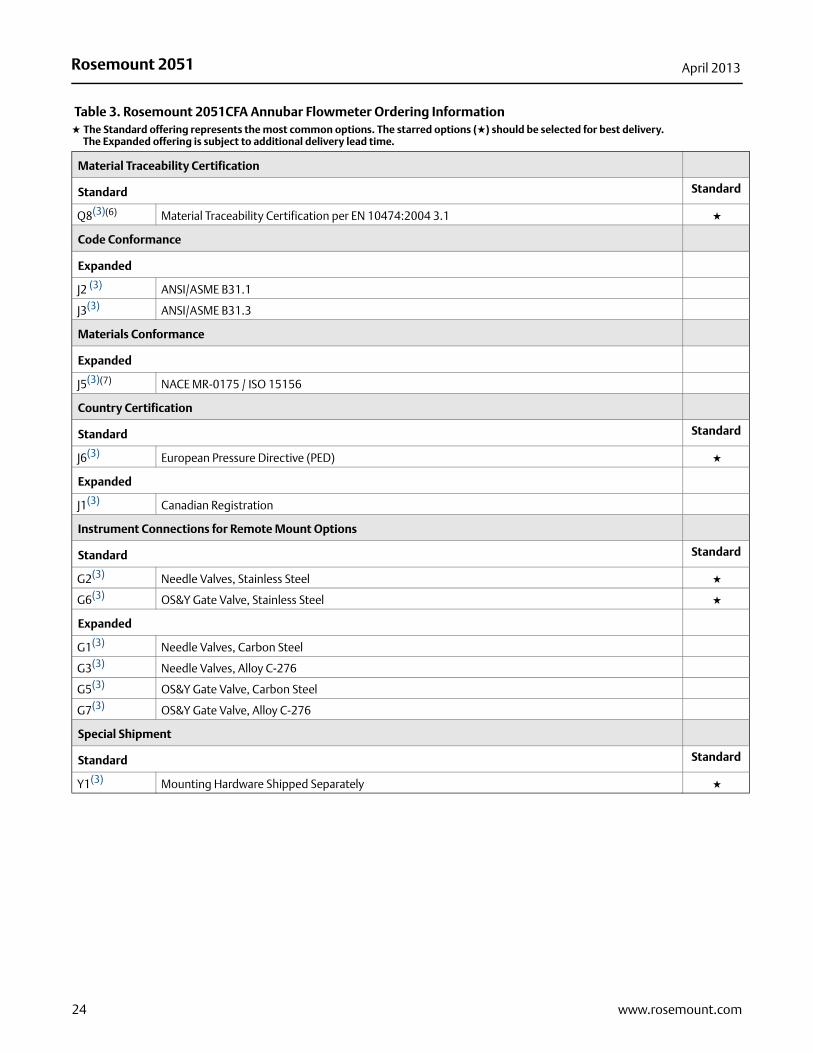
Material Traceability Certification
Standard Standard
Q8(3)(6) Material Traceability Certification per EN 10474:2004 3.1 ★
Code Conformance
Expanded
J2 (3) ANSI/ASME B31.1
J3(3) ANSI/ASME B31.3
Materials Conformance
Expanded
J5(3)(7) NACE MR-0175 / ISO 15156
Country Certification
Standard Standard
J6(3) European Pressure Directive (PED) ★
Expanded
J1(3) Canadian Registration
Instrument Connections for Remote Mount Options
Standard Standard
G2(3) Needle Valves, Stainless Steel ★
G6(3) OS&Y Gate Valve, Stainless Steel ★
Expanded
G1(3) Needle Valves, Carbon Steel
G3(3) Needle Valves, Alloy C-276
G5(3) OS&Y Gate Valve, Carbon Steel
G7(3) OS&Y Gate Valve, Alloy C-276
Special Shipment
Standard Standard
Y1(3) Mounting Hardware Shipped Separately ★
Table 3. Rosemount 2051CFA Annubar Flowmeter Ordering Information★ The Standard offering represents the most common options. The starred options (★) should be selected for best delivery.__The Expanded offering is subject to additional delivery lead time.
24 www.rosemount.com

Rosemount 2051April 2013
25www.rosemount.com
Product Certifications
Standard Standard
E1(3) ATEX Flameproof ★
E2(3) INMETRO Flameproof ★
E3(3) China Flameproof ★
E5 FM Explosion-proof, Dust Ignition-proof ★
E6 CSA Explosion-proof, Dust Ignition-proof, Division 2 ★
E7(3) IECEx Flameproof ★
I1(3) ATEX Intrinsic Safety ★
I2(3) INMETRO Intrinsically Safe ★
I3(3) China Intrinsic Safety ★
I5 FM Intrinsically Safe, Division 2 ★
I6 CSA Intrinsically Safe ★
I7(3) IECEx Intrinsic Safety ★
IA(3)(8) ATEX FISCO Intrinsic Safety; for FOUNDATION fieldbus protocol only ★
IE(3)(8) FM FISCO Intrinsically Safe ★
IF(3)(8) CSA FISCO Intrinsically Safe ★
IG(3)(8) IECEx FISCO Intrinsically Safe ★
K1(3) ATEX Flameproof, Intrinsic Safety, Type n, Dust ★
K5 FM Explosion-proof, Dust Ignition-proof, Intrinsically Safe, Division 2 (combination of E5 and I5) ★
K6 CSA Explosion-proof, Dust Ignition-proof, Intrinsically Safe, Division 2 (combination of E6 and I6) ★
K7(3) IECEx Flameproof, Dust Ignition-proof, Intrinsic Safety, Type n (combination of E7, I7, and N7) ★
KA(3) ATEX and CSA Flameproof, Intrinsically Safe, Division 2 ★
KBFM and CSA Explosion-proof, Dust Ignition-proof, Intrinsically Safe, Division 2 (combination of E5, E6, I5, and I6)
★
KC(3) FM and ATEX Explosion-proof, Intrinsically Safe, Division 2 ★
KD(3) FM, CSA, and ATEX Explosion-proof, Intrinsically Safe (combination of E5, I5, E6, I6, E1, and I1) ★
N1(3) ATEX Type n ★
N7(3) IECEx Type n ★
ND(3) ATEX Dust ★
Sensor Fill Fluid and O-ring Options
Standard Standard
L1(3)(9) Inert Sensor Fill Fluid ★
L2(3) Graphite-Filled (PTFE) O-ring ★
LA(3)(9) Inert Sensor Fill Fluid and Graphite-Filled (PTFE) O-ring ★
Display and Interface Options
Standard Standard
M4(3)(10) LCD Display with Local Operator Interface ★
M5(3) LCD display ★
Table 3. Rosemount 2051CFA Annubar Flowmeter Ordering Information★ The Standard offering represents the most common options. The starred options (★) should be selected for best delivery.__The Expanded offering is subject to additional delivery lead time.
Rosemount 2051 April 2013
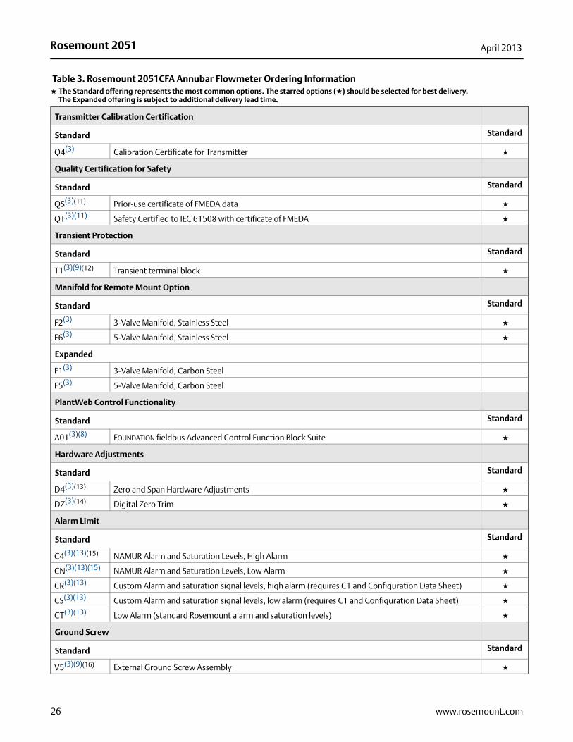
Transmitter Calibration Certification
Standard Standard
Q4(3) Calibration Certificate for Transmitter ★
Quality Certification for Safety
Standard Standard
QS(3)(11) Prior-use certificate of FMEDA data ★
QT(3)(11) Safety Certified to IEC 61508 with certificate of FMEDA ★
Transient Protection
Standard Standard
T1(3)(9)(12) Transient terminal block ★
Manifold for Remote Mount Option
Standard Standard
F2(3) 3-Valve Manifold, Stainless Steel ★
F6(3) 5-Valve Manifold, Stainless Steel ★
Expanded
F1(3) 3-Valve Manifold, Carbon Steel
F5(3) 5-Valve Manifold, Carbon Steel
PlantWeb Control Functionality
Standard Standard
A01(3)(8) FOUNDATION fieldbus Advanced Control Function Block Suite ★
Hardware Adjustments
Standard Standard
D4(3)(13) Zero and Span Hardware Adjustments ★
DZ(3)(14) Digital Zero Trim ★
Alarm Limit
Standard Standard
C4(3)(13)(15) NAMUR Alarm and Saturation Levels, High Alarm ★
CN(3)(13)(15) NAMUR Alarm and Saturation Levels, Low Alarm ★
CR(3)(13) Custom Alarm and saturation signal levels, high alarm (requires C1 and Configuration Data Sheet) ★
CS(3)(13) Custom Alarm and saturation signal levels, low alarm (requires C1 and Configuration Data Sheet) ★
CT(3)(13) Low Alarm (standard Rosemount alarm and saturation levels) ★
Ground Screw
Standard Standard
V5(3)(9)(16) External Ground Screw Assembly ★
Table 3. Rosemount 2051CFA Annubar Flowmeter Ordering Information★ The Standard offering represents the most common options. The starred options (★) should be selected for best delivery.__The Expanded offering is subject to additional delivery lead time.
26 www.rosemount.com
Rosemount 2051April 2013
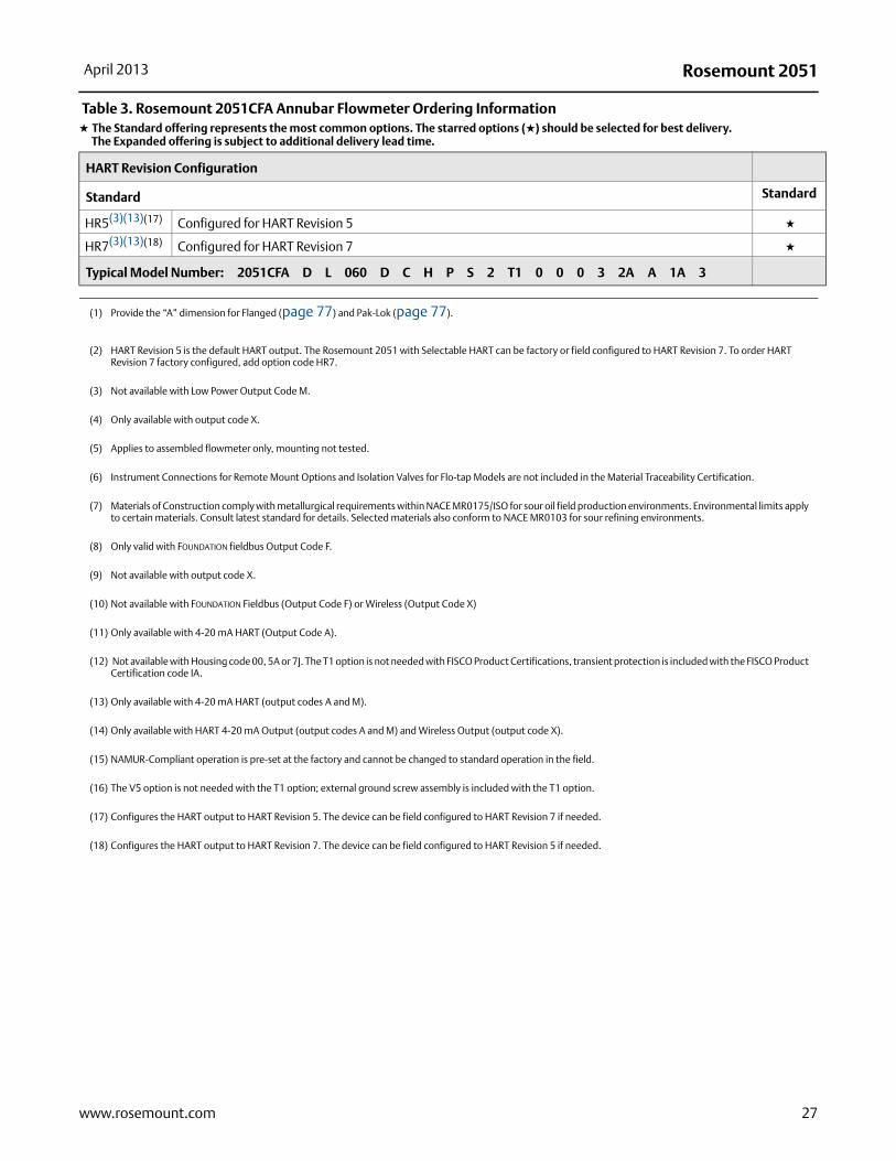
HART Revision Configuration
Standard Standard
HR5(3)(13)(17) Configured for HART Revision 5 ★
HR7(3)(13)(18) Configured for HART Revision 7 ★
Typical Model Number: 2051CFA D L 060 D C H P S 2 T1 0 0 0 3 2A A 1A 3
(1) Provide the “A” dimension for Flanged (page 77) and Pak-Lok (page 77).
(2) HART Revision 5 is the default HART output. The Rosemount 2051 with Selectable HART can be factory or field configured to HART Revision 7. To order HART Revision 7 factory configured, add option code HR7.
(3) Not available with Low Power Output Code M.
(4) Only available with output code X.
(5) Applies to assembled flowmeter only, mounting not tested.
(6) Instrument Connections for Remote Mount Options and Isolation Valves for Flo-tap Models are not included in the Material Traceability Certification.
(7) Materials of Construction comply with metallurgical requirements within NACE MR0175/ISO for sour oil field production environments. Environmental limits apply to certain materials. Consult latest standard for details. Selected materials also conform to NACE MR0103 for sour refining environments.
(8) Only valid with FOUNDATION fieldbus Output Code F.
(9) Not available with output code X.
(10) Not available with FOUNDATION Fieldbus (Output Code F) or Wireless (Output Code X)
(11) Only available with 4-20 mA HART (Output Code A).
(12) Not available with Housing code 00, 5A or 7J. The T1 option is not needed with FISCO Product Certifications, transient protection is included with the FISCO Product Certification code IA.
(13) Only available with 4-20 mA HART (output codes A and M).
(14) Only available with HART 4-20 mA Output (output codes A and M) and Wireless Output (output code X).
(15) NAMUR-Compliant operation is pre-set at the factory and cannot be changed to standard operation in the field.
(16) The V5 option is not needed with the T1 option; external ground screw assembly is included with the T1 option.
(17) Configures the HART output to HART Revision 5. The device can be field configured to HART Revision 7 if needed.
(18) Configures the HART output to HART Revision 7. The device can be field configured to HART Revision 5 if needed.
Table 3. Rosemount 2051CFA Annubar Flowmeter Ordering Information★ The Standard offering represents the most common options. The starred options (★) should be selected for best delivery.__The Expanded offering is subject to additional delivery lead time.
27www.rosemount.com

Rosemount 2051 April 2013
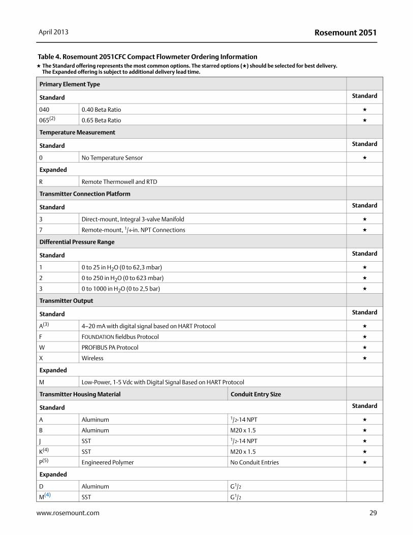
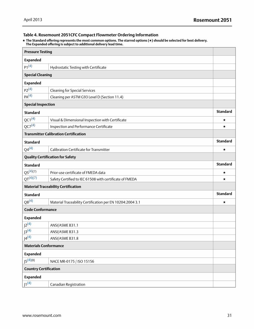
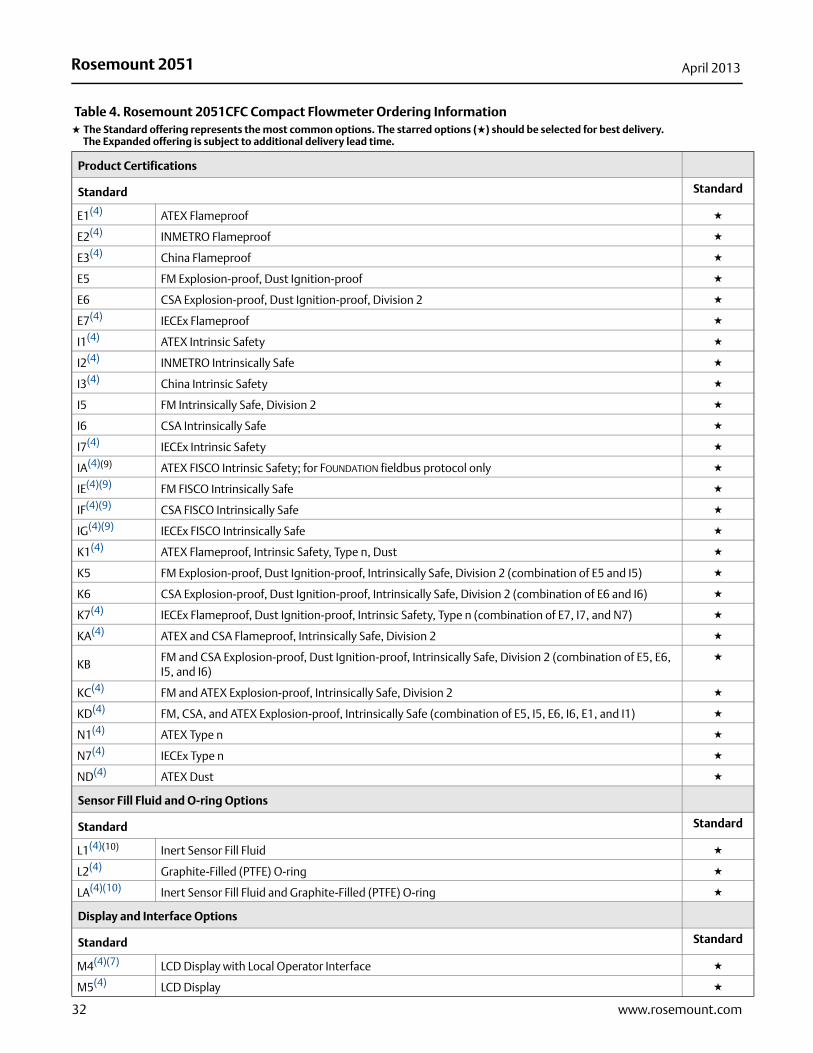
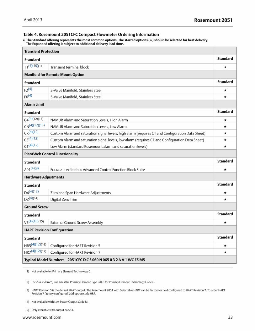
Table 4. Rosemount 2051CFC Compact Flowmeter Ordering Information★ The Standard offering represents the most common options. The starred options (★) should be selected for best delivery.__The Expanded offering is subject to additional delivery lead time.
Model Product Description
2051CFC Compact Flowmeter
Measurement Type
Standard Standard
D Differential Pressure ★
Primary Element Technology
Standard Standard
C Conditioning Orifice Plate ★
P Orifice Plate ★
Material Type
Standard Standard
S 316 SST ★
Line Size
Standard Standard
005(1) 1/2-in. (15 mm) ★
010(1) 1-in. (25 mm) ★
015(1) 11/2-in. (40 mm) ★
020 2-in. (50 mm) ★
030 3-in. (80 mm) ★
040 4-in. (100 mm) ★
060 6-in. (150 mm) ★
080 8-in. (200 mm) ★
100 10-in. (250 mm) ★
120 12-in. (300 mm) ★
Primary Element Style
Standard Standard
N Square Edged ★
Additional InformationSpecifications: page 50Certifications: page 60Dimensional Drawings: page 68
Rosemount 2051CFC Compact Flowmeter
28 www.rosemount.com
Rosemount 2051April 2013
Primary Element Type
Standard Standard
040 0.40 Beta Ratio ★
065(2) 0.65 Beta Ratio ★
Temperature Measurement
Standard Standard
0 No Temperature Sensor ★
Expanded
R Remote Thermowell and RTD
Transmitter Connection Platform
Standard Standard
3 Direct-mount, Integral 3-valve Manifold ★
7 Remote-mount, 1/4-in. NPT Connections ★
Differential Pressure Range
Standard Standard
1 0 to 25 in H2O (0 to 62,3 mbar) ★
2 0 to 250 in H2O (0 to 623 mbar) ★
3 0 to 1000 in H2O (0 to 2,5 bar) ★
Transmitter Output
Standard Standard
A(3) 4–20 mA with digital signal based on HART Protocol ★
F FOUNDATION fieldbus Protocol ★
W PROFIBUS PA Protocol ★
X Wireless ★
Expanded
M Low-Power, 1-5 Vdc with Digital Signal Based on HART Protocol
Transmitter Housing Material Conduit Entry Size
Standard Standard
A Aluminum 1/2-14 NPT ★
B Aluminum M20 x 1.5 ★
J SST 1/2-14 NPT ★
K(4) SST M20 x 1.5 ★
P(5) Engineered Polymer No Conduit Entries ★
Expanded
D Aluminum G1/2
M(4) SST G1/2
Table 4. Rosemount 2051CFC Compact Flowmeter Ordering Information★ The Standard offering represents the most common options. The starred options (★) should be selected for best delivery.__The Expanded offering is subject to additional delivery lead time.
29www.rosemount.com

Rosemount 2051 April 2013
Transmitter Performance Class
Standard Standard
1 up to ±2.25% flow rate accuracy, 5:1 flow turndown, 2-year stability ★
Wireless options (Requires Wireless output code X and Engineered Polymer housing code P)
Wireless Transmit Rate, Operating Frequency and Protocol
Standard Standard
WA3 User Configurable Transmit Rate, 2.4GHz WirelessHART ★
Antenna and SmartPower
Standard Standard
WP5 Internal Antenna, Compatible with Green Power Module (I.S. Power Module Sold Separately) ★
Options (Include with selected model number)
Installation Accessories
Standard Standard
AB(4) ANSI Alignment Ring (150#) (Only required for 10-in. (250 mm) and 12-in. (300 mm) line sizes) ★
AC(4) ANSI Alignment Ring (300#) (Only required for 10-in. (250 mm) and 12-in. (300 mm) line sizes) ★
AD (4) ANSI Alignment Ring (600#) (Only required for 10-in. (250 mm) and 12-in. (300 mm) line sizes) ★
DG(4) DIN Alignment Ring (PN16) ★
DH(4) DIN Alignment Ring (PN40) ★
DJ(4) DIN Alignment Ring (PN100) ★
Expanded
JB(4) JIS Alignment Ring (10K)
JR(4) JIS Alignment Ring (20K)
JS(4) JIS Alignment Ring (40K)
Remote Adapters
Standard Standard
FE(4) Flange Adapters 316 SST (1/2-in NPT) ★
High Temperature Application
Expanded
HT(4) Graphite Valve Packing (Tmax = 850 °F)
Flow Calibration
Expanded
WC(4)(6) Flow Calibration Certification (3 point)
WD(4)(6) Discharge Coefficient Verification (full 10 point)
Table 4. Rosemount 2051CFC Compact Flowmeter Ordering Information★ The Standard offering represents the most common options. The starred options (★) should be selected for best delivery.__The Expanded offering is subject to additional delivery lead time.
30 www.rosemount.com
Rosemount 2051April 2013
Pressure Testing
Expanded
P1(4) Hydrostatic Testing with Certificate
Special Cleaning
Expanded
P2(4) Cleaning for Special Services
PA(4) Cleaning per ASTM G93 Level D (Section 11.4)
Special Inspection
Standard Standard
QC1(4) Visual & Dimensional Inspection with Certificate ★
QC7(4) Inspection and Performance Certificate ★
Transmitter Calibration Certification
Standard Standard
Q4(4) Calibration Certificate for Transmitter ★
Quality Certification for Safety
Standard Standard
QS(4)(7) Prior-use certificate of FMEDA data ★
QT(4)(7) Safety Certified to IEC 61508 with certificate of FMEDA ★
Material Traceability Certification
Standard Standard
Q8(4) Material Traceability Certification per EN 10204:2004 3.1 ★
Code Conformance
Expanded
J2(4) ANSI/ASME B31.1
J3(4) ANSI/ASME B31.3
J4(4) ANSI/ASME B31.8
Materials Conformance
Expanded
J5(4)(8) NACE MR-0175 / ISO 15156
Country Certification
Expanded
J1(4) Canadian Registration
Table 4. Rosemount 2051CFC Compact Flowmeter Ordering Information★ The Standard offering represents the most common options. The starred options (★) should be selected for best delivery.__The Expanded offering is subject to additional delivery lead time.
31www.rosemount.com
Rosemount 2051 April 2013
32 www.rosemount.com
Product Certifications
Standard Standard
E1(4) ATEX Flameproof ★
E2(4) INMETRO Flameproof ★
E3(4) China Flameproof ★
E5 FM Explosion-proof, Dust Ignition-proof ★
E6 CSA Explosion-proof, Dust Ignition-proof, Division 2 ★
E7(4) IECEx Flameproof ★
I1(4) ATEX Intrinsic Safety ★
I2(4) INMETRO Intrinsically Safe ★
I3(4) China Intrinsic Safety ★
I5 FM Intrinsically Safe, Division 2 ★
I6 CSA Intrinsically Safe ★
I7(4) IECEx Intrinsic Safety ★
IA(4)(9) ATEX FISCO Intrinsic Safety; for FOUNDATION fieldbus protocol only ★
IE(4)(9) FM FISCO Intrinsically Safe ★
IF(4)(9) CSA FISCO Intrinsically Safe ★
IG(4)(9) IECEx FISCO Intrinsically Safe ★
K1(4) ATEX Flameproof, Intrinsic Safety, Type n, Dust ★
K5 FM Explosion-proof, Dust Ignition-proof, Intrinsically Safe, Division 2 (combination of E5 and I5) ★
K6 CSA Explosion-proof, Dust Ignition-proof, Intrinsically Safe, Division 2 (combination of E6 and I6) ★
K7(4) IECEx Flameproof, Dust Ignition-proof, Intrinsic Safety, Type n (combination of E7, I7, and N7) ★
KA(4) ATEX and CSA Flameproof, Intrinsically Safe, Division 2 ★
KBFM and CSA Explosion-proof, Dust Ignition-proof, Intrinsically Safe, Division 2 (combination of E5, E6, I5, and I6)
★
KC(4) FM and ATEX Explosion-proof, Intrinsically Safe, Division 2 ★
KD(4) FM, CSA, and ATEX Explosion-proof, Intrinsically Safe (combination of E5, I5, E6, I6, E1, and I1) ★
N1(4) ATEX Type n ★
N7(4) IECEx Type n ★
ND(4) ATEX Dust ★
Sensor Fill Fluid and O-ring Options
Standard Standard
L1(4)(10) Inert Sensor Fill Fluid ★
L2(4) Graphite-Filled (PTFE) O-ring ★
LA(4)(10) Inert Sensor Fill Fluid and Graphite-Filled (PTFE) O-ring ★
Display and Interface Options
Standard Standard
M4(4)(7) LCD Display with Local Operator Interface ★
M5(4) LCD Display ★
Table 4. Rosemount 2051CFC Compact Flowmeter Ordering Information★ The Standard offering represents the most common options. The starred options (★) should be selected for best delivery.__The Expanded offering is subject to additional delivery lead time.
Rosemount 2051April 2013
Transient Protection
Standard Standard
T1(4)(10)(11) Transient terminal block ★
Manifold for Remote Mount Option
Standard Standard
F2(4) 3-Valve Manifold, Stainless Steel ★
F6(4) 5-Valve Manifold, Stainless Steel ★
Alarm Limit
Standard Standard
C4(4)(12)(13) NAMUR Alarm and Saturation Levels, High Alarm ★
CN(4)(12)(13) NAMUR Alarm and Saturation Levels, Low Alarm ★
CR(4)(12) Custom Alarm and saturation signal levels, high alarm (requires C1 and Configuration Data Sheet) ★
CS(4)(12) Custom Alarm and saturation signal levels, low alarm (requires C1 and Configuration Data Sheet) ★
CT(4)(12) Low Alarm (standard Rosemount alarm and saturation levels) ★
PlantWeb Control Functionality
Standard Standard
A01(4)(9) FOUNDATION fieldbus Advanced Control Function Block Suite ★
Hardware Adjustments
Standard Standard
D4(4)(12) Zero and Span Hardware Adjustments ★
DZ(4)(14) Digital Zero Trim ★
Ground Screw
Standard Standard
V5(4)(10)(15) External Ground Screw Assembly ★
HART Revision Configuration
Standard Standard
HR5(4)(12)(16) Configured for HART Revision 5 ★
HR7(4)(12)(17) Configured for HART Revision 7 ★
Typical Model Number: 2051CFC D C S 060 N 065 0 3 2 A A 1 WC E5 M5
(1) Not available for Primary Element Technology C.
(2) For 2-in. (50 mm) line sizes the Primary Element Type is 0.6 for Primary Element Technology Code C.
(3) HART Revision 5 is the default HART output. The Rosemount 2051 with Selectable HART can be factory or field configured to HART Revision 7. To order HART Revision 7 factory configured, add option code HR7.
(4) Not available with Low Power Output Code M.
(5) Only available with output code X.
Table 4. Rosemount 2051CFC Compact Flowmeter Ordering Information★ The Standard offering represents the most common options. The starred options (★) should be selected for best delivery.__The Expanded offering is subject to additional delivery lead time.
33www.rosemount.com
Rosemount 2051 April 2013
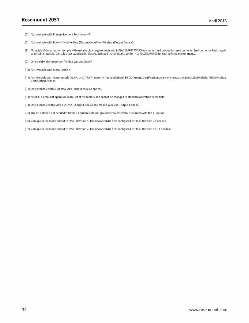
(6) Not available with Primary Element Technology P.
(7) Not available with FOUNDATION Fieldbus (Output Code F) or Wireless (Output Code X).
(8) Materials of Construction comply with metallurgical requirements within NACE MR0175/ISO for sour oil field production environments. Environmental limits apply to certain materials. Consult latest standard for details. Selected materials also conform to NACE MR0103 for sour refining environments.
(9) Only valid with FOUNDATION fieldbus Output Code F.
(10) Not available with output code X.
(11) Not available with Housing code 00, 5A, or 7J. The T1 option is not needed with FISCO Product Certifications, transient protection is included with the FISCO Product Certification code IA.
(12) Only available with 4-20 mA HART (output codes A and M).
(13) NAMUR-Compliant operation is pre-set at the factory and cannot be changed to standard operation in the field.
(14) Only available with HART 4-20 mA (Output Codes A and M) and Wireless (Output Code X).
(15) The V5 option is not needed with the T1 option; external ground screw assembly is included with the T1 option.
(16) Configures the HART output to HART Revision 5. The device can be field configured to HART Revision 7 if needed.
(17) Configures the HART output to HART Revision 7. The device can be field configured to HART Revision 5 if 14 needed.
34 www.rosemount.com
Rosemount 2051April 2013
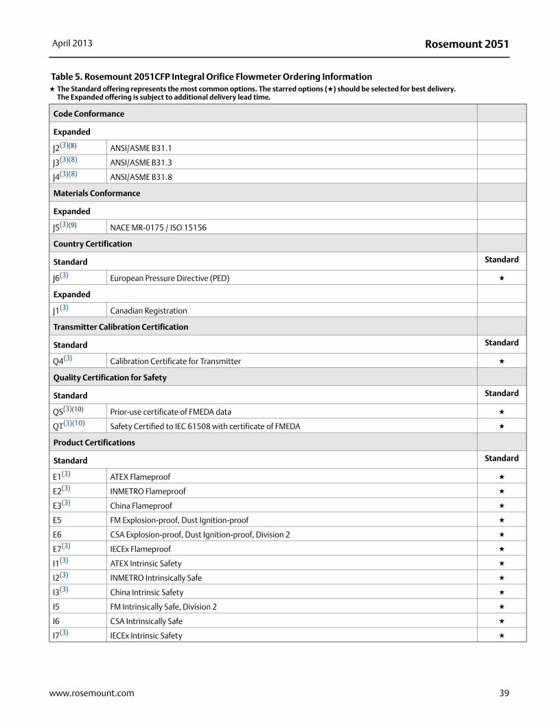
Table 5. Rosemount 2051CFP Integral Orifice Flowmeter Ordering Information★ The Standard offering represents the most common options. The starred options (★) should be selected for best delivery.__The Expanded offering is subject to additional delivery lead time.
Model Product Description
2051CFP Integral Orifice Flowmeter
Measurement Type
Standard Standard
D Differential Pressure ★
Material Type
Standard Standard
S 316 SST ★
Line Size
Standard Standard
005 1/2-in. (15 mm) ★
010 1-in. (25 mm) ★
015 11/2-in. (40 mm) ★
Process Connection
Standard Standard
T1 NPT Female Body (Not Available with Remote Thermowell and RTD) ★
S1(1) Socket Weld Body (Not Available with Remote Thermowell and RTD) ★
P1 Pipe Ends: NPT Threaded ★
P2 Pipe ends: Beveled ★
D1 Pipe Ends: Flanged, DIN PN16, slip-on ★
D2 Pipe Ends: Flanged, DIN PN40, slip-on ★
D3 Pipe Ends: Flanged, DIN PN100, slip-on ★
W1 Pipe Ends: Flanged, RF, ANSI Class 150, weld-neck ★
W3 Pipe Ends: Flanged, RF, ANSI Class 300, weld-neck ★
W6 Pipe Ends: Flanged, RF, ANSI Class 600, weld-neck ★
Additional InformationSpecifications: page 50Certifications: page 60Dimensional Drawings: page 68
Rosemount 2051CFP Integral Orifice Flowmeter
35www.rosemount.com
Rosemount 2051 April 2013
Expanded
A1 Pipe Ends: Flanged, RF, ANSI Class 150, slip-on
A3 Pipe Ends: Flanged, RF, ANSI Class 300, slip-on
A6 Pipe Ends: Flanged, RF, ANSI Class 600, slip-on
R1 Pipe Ends: Flanged, RTJ, ANSI Class 150, slip-on
R3 Pipe Ends: Flanged, RTJ, ANSI Class 300, slip-on
R6 Pipe Ends: Flanged, RTJ, ANSI Class 600, slip-on
Orifice Plate Material
Standard Standard
S 316 SST ★
Bore Size Option
Standard Standard
0066 0.066-in. (1.68 mm) for 1/2-in. Pipe ★
0109 0.109-in. (2.77 mm) for 1/2-in. Pipe ★
0160 0.160-in. (4.06 mm) for 1/2-in. Pipe ★
0196 0.196-in. (4.98 mm) for 1/2-in. Pipe ★
0260 0.260-in. (6.60 mm) for 1/2-in. Pipe ★
0340 0.340-in. (8.64 mm) for 1/2-in. Pipe ★
0150 0.150-in. (3.81 mm) for 1-in. Pipe ★
0250 0.250-in. (6.35 mm) for 1-in. Pipe ★
0345 0.345-in. (8.76 mm) for 1-in. Pipe ★
0500 0.500-in. (12.70 mm) for 1-in. Pipe ★
0630 0.630-in. (16.00 mm) for 1-in. Pipe ★
0800 0.800-in. (20.32 mm) for 1-in. Pipe ★
0295 0.295-in. (7.49 mm) for 1 1/2-in. Pipe ★
0376 0.376-in. (9.55 mm) for 1 1/2-in. Pipe ★
0512 0.512-in. (13.00 mm) for 1 1/2-in. Pipe ★
0748 0.748-in. (19.00 mm) for 1 1/2-in. Pipe ★
1022 1.022-in. (25.96 mm) for 1 1/2-in. Pipe ★
1184 1.184-in. (30.07 mm) for 1 1/2-in. Pipe ★
Expanded
0010 0.010-in. (0.25 mm) for 1/2-in. Pipe
0014 0.014-in. (0.36 mm) for 1/2-in. Pipe
0020 0.020-in. (0.51 mm) for 1/2-in. Pipe
0034 0.034-in. (0.86 mm) for 1/2-in. Pipe
Table 5. Rosemount 2051CFP Integral Orifice Flowmeter Ordering Information★ The Standard offering represents the most common options. The starred options (★) should be selected for best delivery.__The Expanded offering is subject to additional delivery lead time.
36 www.rosemount.com
Rosemount 2051April 2013
37www.rosemount.com
Transmitter Connection Platform
Standard Standard
D3 Direct-mount, 3-Valve Manifold, SST ★
D5 Direct-mount, 5-Valve Manifold, SST ★
R3 Remote-mount, 3-Valve Manifold, SST ★
R5 Remote-mount, 5-Valve Manifold, SST ★
Differential Pressure Ranges
Standard Standard
1 0 to 25 in H2O (0 to 62,3 mbar) ★
2 0 to 250 in H2O (0 to 623 mbar) ★
3 0 to 1000 in H2O (0 to 2,5 bar) ★
Transmitter Output
Standard Standard
A(2) 4–20 mA with digital signal based on HART protocol ★
F FOUNDATION fieldbus protocol ★
W PROFIBUS PA Protocol ★
X Wireless ★
Expanded
M Low-Power, 1-5 Vdc with Digital Signal Based on HART Protocol
Transmitter Housing Material Conduit Entry Size
Standard Standard
A Aluminum 1/2-14 NPT ★
B Aluminum M20 x 1.5 ★
J SST 1/2-14 NPT ★
K(3) SST M20 x 1.5 ★
P(4) Engineered Polymer No Conduit Entries ★
Expanded
D Aluminum G1/2
M(3) SST G1/2
Transmitter Performance Class
Standard Standard
1 up to ±2.25% flow rate accuracy, 5:1 flow turndown, 2-year stability ★
Wireless options (Requires Wireless output code X and Engineered Polymer housing code P)
Wireless Transmit Rate, Operating Frequency and Protocol
Standard Standard
WA3 User Configurable Transmit Rate, 2.4GHz WirelessHART ★
Table 5. Rosemount 2051CFP Integral Orifice Flowmeter Ordering Information★ The Standard offering represents the most common options. The starred options (★) should be selected for best delivery.__The Expanded offering is subject to additional delivery lead time.
Rosemount 2051 April 2013
Antenna and SmartPower
Standard Standard
WP5 Internal Antenna, Compatible with Green Power Module (I.S. Power Module Sold Separately) ★
Options (Include with selected model number)
Temperature Sensor
Expanded
RT(3)(5) Thermowell and RTD
Optional Connection
Standard Standard
G1(3) DIN 19213 Transmitter Connection ★
Pressure Testing
Expanded
P1(3)(6) Hydrostatic Testing with Certificate
Special Cleaning
Expanded
P2(3) Cleaning for Special Services
PA(3) Cleaning per ASTM G93 Level D (Section 11.4)
Material Testing
Expanded
V1(3) Dye Penetrant Exam
Material Examination
Expanded
V2(3) Radiographic Examination
Flow Calibration
Expanded
WD(3)(7) Discharge Coefficient Verification
Special Inspection
Standard Standard
QC1(3) Visual & Dimensional Inspection with Certificate ★
QC7(3) Inspection and Performance Certificate ★
Material Traceability Certification
Standard Standard
Q8(3) Material Traceability Certification per EN 10204:2004 3.1 ★
Table 5. Rosemount 2051CFP Integral Orifice Flowmeter Ordering Information★ The Standard offering represents the most common options. The starred options (★) should be selected for best delivery.__The Expanded offering is subject to additional delivery lead time.
38 www.rosemount.com
Rosemount 2051April 2013
Code Conformance
Expanded
J2(3)(8) ANSI/ASME B31.1
J3(3)(8) ANSI/ASME B31.3
J4(3)(8) ANSI/ASME B31.8
Materials Conformance
Expanded
J5(3)(9) NACE MR-0175 / ISO 15156
Country Certification
Standard Standard
J6(3) European Pressure Directive (PED) ★
Expanded
J1(3) Canadian Registration
Transmitter Calibration Certification
Standard Standard
Q4(3) Calibration Certificate for Transmitter ★
Quality Certification for Safety
Standard Standard
QS(3)(10) Prior-use certificate of FMEDA data ★
QT(3)(10) Safety Certified to IEC 61508 with certificate of FMEDA ★
Product Certifications
Standard Standard
E1(3) ATEX Flameproof ★
E2(3) INMETRO Flameproof ★
E3(3) China Flameproof ★
E5 FM Explosion-proof, Dust Ignition-proof ★
E6 CSA Explosion-proof, Dust Ignition-proof, Division 2 ★
E7(3) IECEx Flameproof ★
I1(3) ATEX Intrinsic Safety ★
I2(3) INMETRO Intrinsically Safe ★
I3(3) China Intrinsic Safety ★
I5 FM Intrinsically Safe, Division 2 ★
I6 CSA Intrinsically Safe ★
I7(3) IECEx Intrinsic Safety ★
Table 5. Rosemount 2051CFP Integral Orifice Flowmeter Ordering Information★ The Standard offering represents the most common options. The starred options (★) should be selected for best delivery.__The Expanded offering is subject to additional delivery lead time.
39www.rosemount.com
Rosemount 2051 April 2013
40 www.rosemount.com
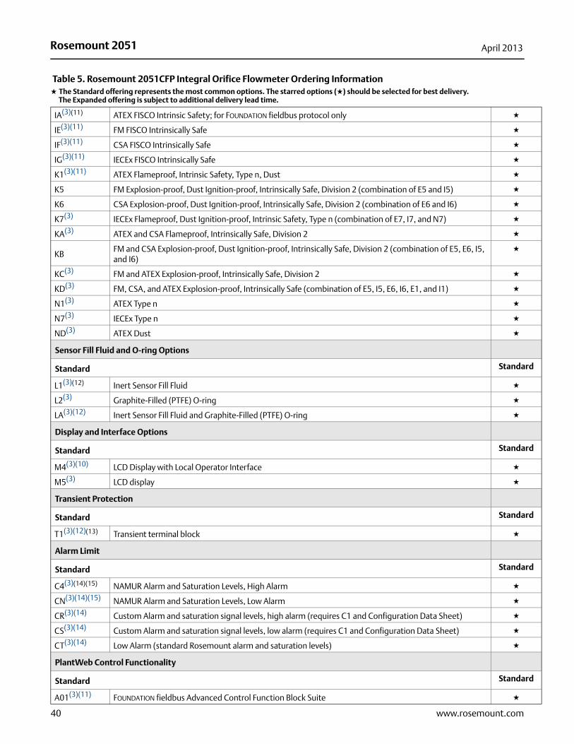
IA(3)(11) ATEX FISCO Intrinsic Safety; for FOUNDATION fieldbus protocol only ★
IE(3)(11) FM FISCO Intrinsically Safe ★
IF(3)(11) CSA FISCO Intrinsically Safe ★
IG(3)(11) IECEx FISCO Intrinsically Safe ★
K1(3)(11) ATEX Flameproof, Intrinsic Safety, Type n, Dust ★
K5 FM Explosion-proof, Dust Ignition-proof, Intrinsically Safe, Division 2 (combination of E5 and I5) ★
K6 CSA Explosion-proof, Dust Ignition-proof, Intrinsically Safe, Division 2 (combination of E6 and I6) ★
K7(3) IECEx Flameproof, Dust Ignition-proof, Intrinsic Safety, Type n (combination of E7, I7, and N7) ★
KA(3) ATEX and CSA Flameproof, Intrinsically Safe, Division 2 ★
KBFM and CSA Explosion-proof, Dust Ignition-proof, Intrinsically Safe, Division 2 (combination of E5, E6, I5, and I6)
★
KC(3) FM and ATEX Explosion-proof, Intrinsically Safe, Division 2 ★
KD(3) FM, CSA, and ATEX Explosion-proof, Intrinsically Safe (combination of E5, I5, E6, I6, E1, and I1) ★
N1(3) ATEX Type n ★
N7(3) IECEx Type n ★
ND(3) ATEX Dust ★
Sensor Fill Fluid and O-ring Options
Standard Standard
L1(3)(12) Inert Sensor Fill Fluid ★
L2(3) Graphite-Filled (PTFE) O-ring ★
LA(3)(12) Inert Sensor Fill Fluid and Graphite-Filled (PTFE) O-ring ★
Display and Interface Options
Standard Standard
M4(3)(10) LCD Display with Local Operator Interface ★
M5(3) LCD display ★
Transient Protection
Standard Standard
T1(3)(12)(13) Transient terminal block ★
Alarm Limit
Standard Standard
C4(3)(14)(15) NAMUR Alarm and Saturation Levels, High Alarm ★
CN(3)(14)(15) NAMUR Alarm and Saturation Levels, Low Alarm ★
CR(3)(14) Custom Alarm and saturation signal levels, high alarm (requires C1 and Configuration Data Sheet) ★
CS(3)(14) Custom Alarm and saturation signal levels, low alarm (requires C1 and Configuration Data Sheet) ★
CT(3)(14) Low Alarm (standard Rosemount alarm and saturation levels) ★
PlantWeb Control Functionality
Standard Standard
A01(3)(11) FOUNDATION fieldbus Advanced Control Function Block Suite ★
Table 5. Rosemount 2051CFP Integral Orifice Flowmeter Ordering Information★ The Standard offering represents the most common options. The starred options (★) should be selected for best delivery.__The Expanded offering is subject to additional delivery lead time.
Rosemount 2051April 2013
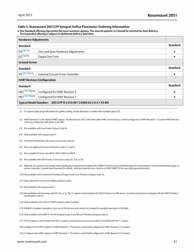
Hardware Adjustments
Standard Standard
D4(3)(14) Zero and Span Hardware Adjustments ★
DZ(3)(16) Digital Zero Trim ★
Ground Screw
Standard Standard
V5(3)(12)(17) External Ground Screw Assembly ★
HART Revision Configuration
Standard Standard
HR5(3)(14)(18) Configured for HART Revision 5 ★
HR7(3)(14)(19) Configured for HART Revision 7 ★
Typical Model Number: 2051CFP D S 010 W1 S 0500 D3 2 A A 1 E5 M5
(1) To improve pipe perpendicularity for gasket sealing, socket diameter is smaller than standard pipe O.D.
(2) HART Revision 5 is the default HART output. The Rosemount 2051 with Selectable HART can be factory or field configured to HART Revision 7. To order HART Revision 7 factory configured, add option code HR7.
(3) Not available with Low Power Output Code M.
(4) Only available with output code X.
(5) Thermowell Material is the same as the body material.
(6) Does not apply to Process Connection codes T1 and S1.
(7) Not available for bore sizes 0010, 0014, 0020, or 0034.
(8) Not available with DIN Process Connection codes D1, D2, or D3.
(9) Materials of Construction comply with metallurgical requirements within NACE MR0175/ISO for sour oil field production environments. Environmental limits apply to certain materials. Consult latest standard for details. Selected materials also conform to NACE MR0103 for sour refining environments.
(10) Not available with FOUNDATION Fieldbus (Output Code F) or Wireless (Output Code X).
(11) Only valid with FOUNDATION fieldbus Output Code F.
(12) Not available with output code X.
(13) Not available with Housing code 00, 5A, or 7J. The T1 option is not needed with FISCO Product Certifications, transient protection is included with the FISCO Product Certification code IA.
(14) Only available with 4-20 mA HART (output codes A and M).
(15) NAMUR-Compliant operation is pre-set at the factory and cannot be changed to standard operation in the field.
(16) Only available with HART 4-10 mA (Output Codes A and M) and Wireless (Output Code X).
(17) The V5 option is not needed with the T1 option; external ground screw assembly is included with the T1 option.
(18) Configures the HART output to HART Revision 5. The device can be field configured to HART Revision 7 if needed.
(19) Configures the HART output to HART Revision 7. The device can be field configured to HART Revision 5 if needed.
Table 5. Rosemount 2051CFP Integral Orifice Flowmeter Ordering Information★ The Standard offering represents the most common options. The starred options (★) should be selected for best delivery.__The Expanded offering is subject to additional delivery lead time.
41www.rosemount.com
Rosemount 2051 April 2013
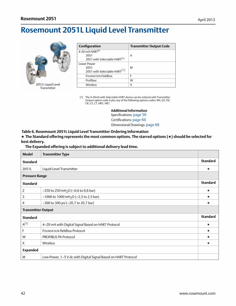
Rosemount 2051L Liquid Level Transmitter
Additional InformationSpecifications: page 50Certifications: page 60Dimensional Drawings: page 68
Configuration Transmitter Output Code
4-20 mA HART®
20512051 with Selectable HART(1)
(1) The 4-20mA with Selectable HART device can be ordered with Transmitter Output option code A plus any of the following options codes: M4, QT, DZ, CR, CS, CT, HR5, HR7.
A
Lower Power20512051 with Selectable HART(1)
M
FOUNDATION Fieldbus FProfibus WWireless X
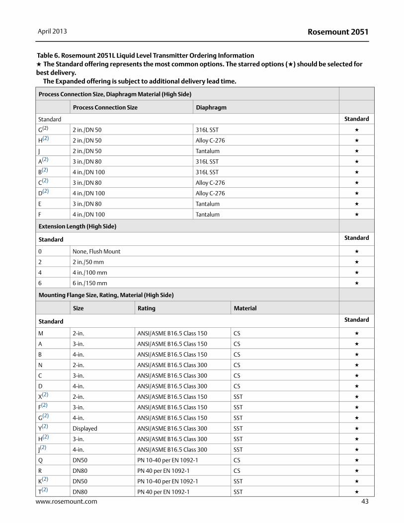
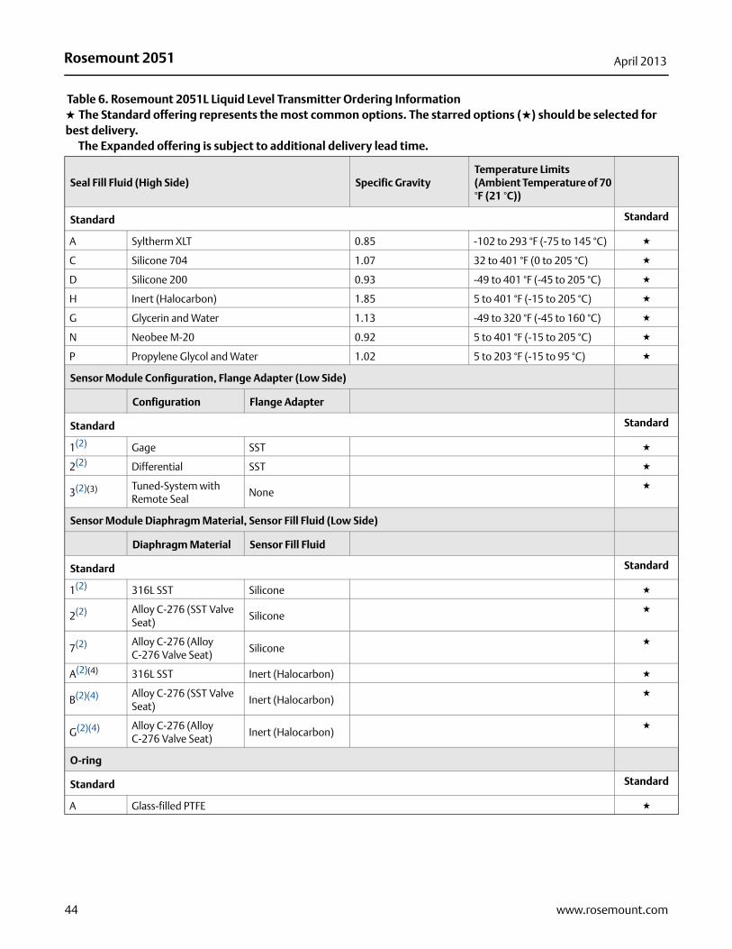
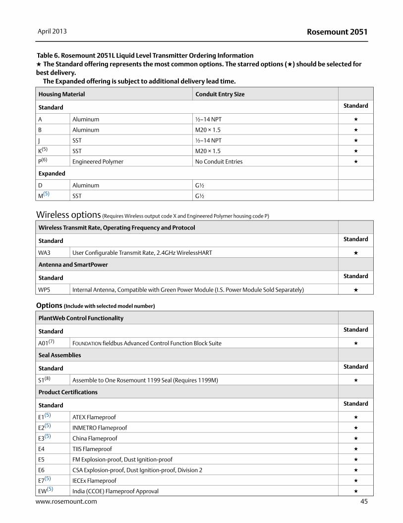
Table 6. Rosemount 2051L Liquid Level Transmitter Ordering Information★ The Standard offering represents the most common options. The starred options (★) should be selected for best delivery.__The Expanded offering is subject to additional delivery lead time.
Model Transmitter Type
Standard Standard
2051L Liquid Level Transmitter ★
Pressure Range
Standard Standard
2 –250 to 250 inH2O (–0,6 to 0,6 bar) ★
3 –1000 to 1000 inH2O (–2,5 to 2,5 bar) ★
4 –300 to 300 psi (–20,7 to 20,7 bar) ★
Transmitter Output
Standard Standard
A(1) 4–20 mA with Digital Signal Based on HART Protocol ★
F FOUNDATION fieldbus Protocol ★
W PROFIBUS PA Protocol ★
X Wireless ★
Expanded
M Low-Power, 1–5 V dc with Digital Signal Based on HART Protocol
2051L Liquid Level Transmitter
42 www.rosemount.com
Rosemount 2051April 2013
43www.rosemount.com
Process Connection Size, Diaphragm Material (High Side)
Process Connection Size Diaphragm
Standard Standard
G(2) 2 in./DN 50 316L SST ★
H(2) 2 in./DN 50 Alloy C-276 ★
J 2 in./DN 50 Tantalum ★
A(2) 3 in./DN 80 316L SST ★
B(2) 4 in./DN 100 316L SST ★
C(2) 3 in./DN 80 Alloy C-276 ★
D(2) 4 in./DN 100 Alloy C-276 ★
E 3 in./DN 80 Tantalum ★
F 4 in./DN 100 Tantalum ★
Extension Length (High Side)
Standard Standard
0 None, Flush Mount ★
2 2 in./50 mm ★
4 4 in./100 mm ★
6 6 in./150 mm ★
Mounting Flange Size, Rating, Material (High Side)
Size Rating Material
Standard Standard
M 2-in. ANSI/ASME B16.5 Class 150 CS ★
A 3-in. ANSI/ASME B16.5 Class 150 CS ★
B 4-in. ANSI/ASME B16.5 Class 150 CS ★
N 2-in. ANSI/ASME B16.5 Class 300 CS ★
C 3-in. ANSI/ASME B16.5 Class 300 CS ★
D 4-in. ANSI/ASME B16.5 Class 300 CS ★
X(2) 2-in. ANSI/ASME B16.5 Class 150 SST ★
F(2) 3-in. ANSI/ASME B16.5 Class 150 SST ★
G(2) 4-in. ANSI/ASME B16.5 Class 150 SST ★
Y(2) Displayed ANSI/ASME B16.5 Class 300 SST ★
H(2) 3-in. ANSI/ASME B16.5 Class 300 SST ★
J(2) 4-in. ANSI/ASME B16.5 Class 300 SST ★
Q DN50 PN 10-40 per EN 1092-1 CS ★
R DN80 PN 40 per EN 1092-1 CS ★
K(2) DN50 PN 10-40 per EN 1092-1 SST ★
T(2) DN80 PN 40 per EN 1092-1 SST ★
Table 6. Rosemount 2051L Liquid Level Transmitter Ordering Information★ The Standard offering represents the most common options. The starred options (★) should be selected for best delivery.__The Expanded offering is subject to additional delivery lead time.
Rosemount 2051 April 2013
Seal Fill Fluid (High Side) Specific GravityTemperature Limits (Ambient Temperature of 70 °F (21 °C))
Standard Standard
A Syltherm XLT 0.85 -102 to 293 °F (-75 to 145 °C) ★
C Silicone 704 1.07 32 to 401 °F (0 to 205 °C) ★
D Silicone 200 0.93 -49 to 401 °F (-45 to 205 °C) ★
H Inert (Halocarbon) 1.85 5 to 401 °F (-15 to 205 °C) ★
G Glycerin and Water 1.13 -49 to 320 °F (-45 to 160 °C) ★
N Neobee M-20 0.92 5 to 401 °F (-15 to 205 °C) ★
P Propylene Glycol and Water 1.02 5 to 203 °F (-15 to 95 °C) ★
Sensor Module Configuration, Flange Adapter (Low Side)
Configuration Flange Adapter
Standard Standard
1(2) Gage SST ★
2(2) Differential SST ★
3(2)(3) Tuned-System with Remote Seal
None★
Sensor Module Diaphragm Material, Sensor Fill Fluid (Low Side)
Diaphragm Material Sensor Fill Fluid
Standard Standard
1(2) 316L SST Silicone ★
2(2) Alloy C-276 (SST Valve Seat)
Silicone★
7(2) Alloy C-276 (Alloy C-276 Valve Seat)
Silicone★
A(2)(4) 316L SST Inert (Halocarbon) ★
B(2)(4) Alloy C-276 (SST Valve Seat)
Inert (Halocarbon)★
G(2)(4) Alloy C-276 (Alloy C-276 Valve Seat)
Inert (Halocarbon)★
O-ring
Standard Standard
A Glass-filled PTFE ★
Table 6. Rosemount 2051L Liquid Level Transmitter Ordering Information★ The Standard offering represents the most common options. The starred options (★) should be selected for best delivery.__The Expanded offering is subject to additional delivery lead time.
44 www.rosemount.com
Rosemount 2051April 2013
45www.rosemount.com
Housing Material Conduit Entry Size
Standard Standard
A Aluminum ½–14 NPT ★
B Aluminum M20 × 1.5 ★
J SST ½–14 NPT ★
K(5) SST M20 × 1.5 ★
P(6) Engineered Polymer No Conduit Entries ★
Expanded
D Aluminum G½
M(5) SST G½
Wireless options (Requires Wireless output code X and Engineered Polymer housing code P)
Wireless Transmit Rate, Operating Frequency and Protocol
Standard Standard
WA3 User Configurable Transmit Rate, 2.4GHz WirelessHART ★
Antenna and SmartPower
Standard Standard
WP5 Internal Antenna, Compatible with Green Power Module (I.S. Power Module Sold Separately) ★
Options (Include with selected model number)
PlantWeb Control Functionality
Standard Standard
A01(7) FOUNDATION fieldbus Advanced Control Function Block Suite ★
Seal Assemblies
Standard Standard
S1(8) Assemble to One Rosemount 1199 Seal (Requires 1199M) ★
Product Certifications
Standard Standard
E1(5) ATEX Flameproof ★
E2(5) INMETRO Flameproof ★
E3(5) China Flameproof ★
E4 TIIS Flameproof ★
E5 FM Explosion-proof, Dust Ignition-proof ★
E6 CSA Explosion-proof, Dust Ignition-proof, Division 2 ★
E7(5) IECEx Flameproof ★
EW(5) India (CCOE) Flameproof Approval ★
Table 6. Rosemount 2051L Liquid Level Transmitter Ordering Information★ The Standard offering represents the most common options. The starred options (★) should be selected for best delivery.__The Expanded offering is subject to additional delivery lead time.
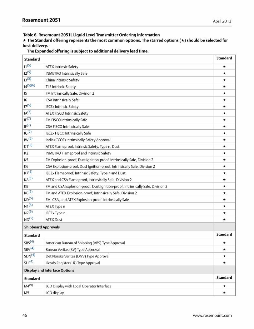
Rosemount 2051 April 2013
Standard Standard
I1(5) ATEX Intrinsic Safety ★
I2(5) INMETRO Intrinsically Safe ★
I3(5) China Intrinsic Safety ★
I4(5)(6) TIIS Intrinsic Safety ★
I5 FM Intrinsically Safe, Division 2 ★
I6 CSA Intrinsically Safe ★
I7(5) IECEx Intrinsic Safety ★
IA(7) ATEX FISCO Intrinsic Safety ★
IE(7) FM FISCO Intrinsically Safe ★
IF(7) CSA FISCO Intrinsically Safe ★
IG(7) IECEx FISCO Intrinsically Safe ★
IW(5) India (CCOE) Intrinsically Safety Approval ★
K1(5) ATEX Flameproof, Intrinsic Safety, Type n, Dust ★
K2 INMETRO Flameproof and Intrinsic Safety ★
K5 FM Explosion-proof, Dust Ignition-proof, Intrinsically Safe, Division 2 ★
K6 CSA Explosion-proof, Dust Ignition-proof, Intrinsically Safe, Division 2 ★
K7(5) IECEx Flameproof, Intrinsic Safety, Type n and Dust ★
KA(5) ATEX and CSA Flameproof, Intrinsically Safe, Division 2 ★
KB FM and CSA Explosion-proof, Dust Ignition-proof, Intrinsically Safe, Division 2 ★
KC(5) FM and ATEX Explosion-proof, Intrinsically Safe, Division 2 ★
KD(5) FM, CSA, and ATEX Explosion-proof, Intrinsically Safe ★
N1(5) ATEX Type n ★
N7(5) IECEx Type n ★
ND(5) ATEX Dust ★
Shipboard Approvals
Standard Standard
SBS(4) American Bureau of Shipping (ABS) Type Approval ★
SBV(4) Bureau Veritas (BV) Type Approval ★
SDN(4) Det Norske Veritas (DNV) Type Approval ★
SLL(4) Lloyds Register (LR) Type Approval ★
Display and Interface Options
Standard Standard
M4(9) LCD Display with Local Operator Interface ★
M5 LCD display ★
Table 6. Rosemount 2051L Liquid Level Transmitter Ordering Information★ The Standard offering represents the most common options. The starred options (★) should be selected for best delivery.__The Expanded offering is subject to additional delivery lead time.
46 www.rosemount.com
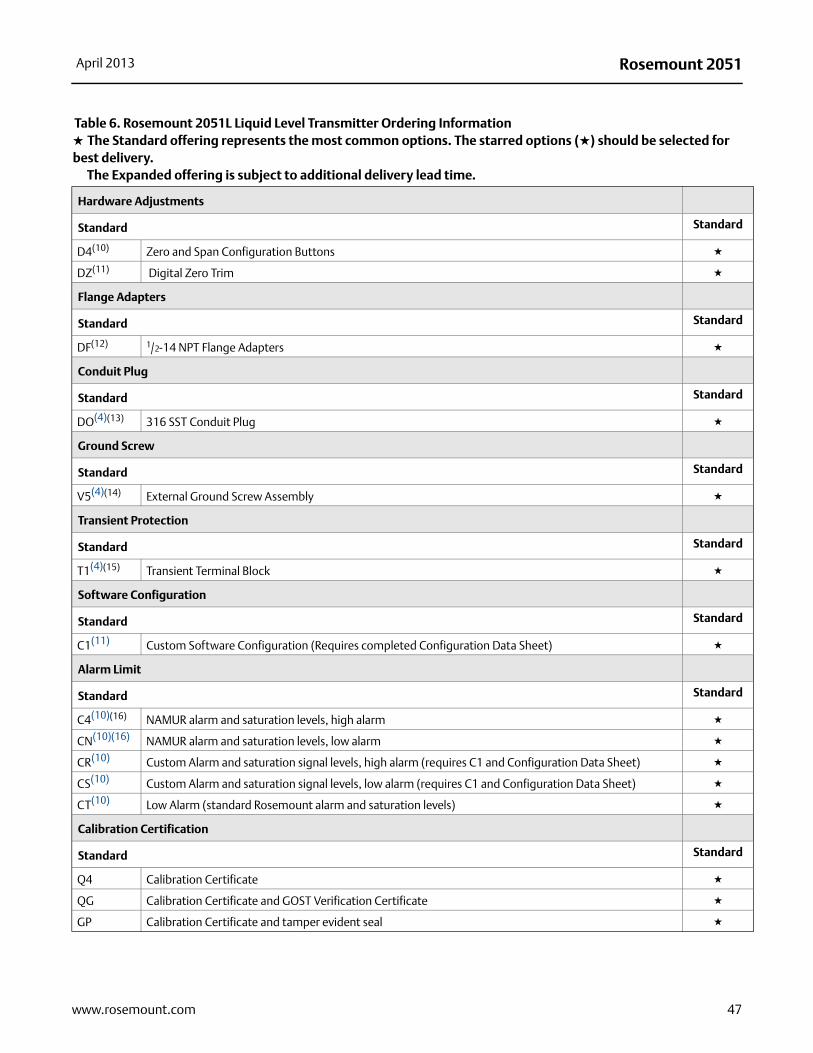
Rosemount 2051April 2013
Hardware Adjustments
Standard Standard
D4(10) Zero and Span Configuration Buttons ★
DZ(11) Digital Zero Trim ★
Flange Adapters
Standard Standard
DF(12) 1/2-14 NPT Flange Adapters ★
Conduit Plug
Standard Standard
DO(4)(13) 316 SST Conduit Plug ★
Ground Screw
Standard Standard
V5(4)(14) External Ground Screw Assembly ★
Transient Protection
Standard Standard
T1(4)(15) Transient Terminal Block ★
Software Configuration
Standard Standard
C1(11) Custom Software Configuration (Requires completed Configuration Data Sheet) ★
Alarm Limit
Standard Standard
C4(10)(16) NAMUR alarm and saturation levels, high alarm ★
CN(10)(16) NAMUR alarm and saturation levels, low alarm ★
CR(10) Custom Alarm and saturation signal levels, high alarm (requires C1 and Configuration Data Sheet) ★
CS(10) Custom Alarm and saturation signal levels, low alarm (requires C1 and Configuration Data Sheet) ★
CT(10) Low Alarm (standard Rosemount alarm and saturation levels) ★
Calibration Certification
Standard Standard
Q4 Calibration Certificate ★
QG Calibration Certificate and GOST Verification Certificate ★
GP Calibration Certificate and tamper evident seal ★
Table 6. Rosemount 2051L Liquid Level Transmitter Ordering Information★ The Standard offering represents the most common options. The starred options (★) should be selected for best delivery.__The Expanded offering is subject to additional delivery lead time.
47www.rosemount.com
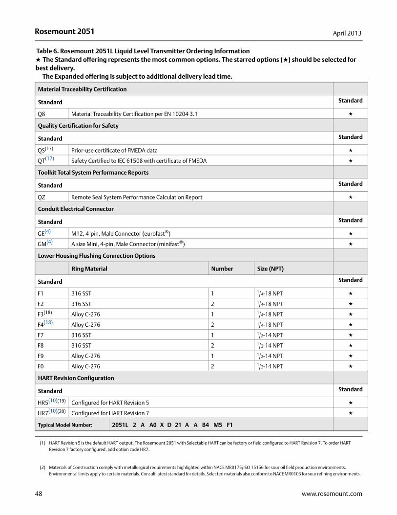
Rosemount 2051 April 2013
Material Traceability Certification
Standard Standard
Q8 Material Traceability Certification per EN 10204 3.1 ★
Quality Certification for Safety
Standard Standard
QS(17) Prior-use certificate of FMEDA data ★
QT(17) Safety Certified to IEC 61508 with certificate of FMEDA ★
Toolkit Total System Performance Reports
Standard Standard
QZ Remote Seal System Performance Calculation Report ★
Conduit Electrical Connector
Standard Standard
GE(4) M12, 4-pin, Male Connector (eurofast®) ★
GM(4) A size Mini, 4-pin, Male Connector (minifast®) ★
Lower Housing Flushing Connection Options
Ring Material Number Size (NPT)
Standard Standard
F1 316 SST 1 1/4-18 NPT ★
F2 316 SST 2 1/4-18 NPT ★
F3(18) Alloy C-276 1 1/4-18 NPT ★
F4(18) Alloy C-276 2 1/4-18 NPT ★
F7 316 SST 1 1/2-14 NPT ★
F8 316 SST 2 1/2-14 NPT ★
F9 Alloy C-276 1 1/2-14 NPT ★
F0 Alloy C-276 2 1/2-14 NPT ★
HART Revision Configuration
Standard Standard
HR5(10)(19) Configured for HART Revision 5 ★
HR7(10)(20) Configured for HART Revision 7 ★
Typical Model Number: 2051L 2 A A0 X D 21 A A B4 M5 F1
(1) HART Revision 5 is the default HART output. The Rosemount 2051 with Selectable HART can be factory or field configured to HART Revision 7. To order HART Revision 7 factory configured, add option code HR7.
(2) Materials of Construction comply with metallurgical requirements highlighted within NACE MR0175/ISO 15156 for sour oil field production environments. Environmental limits apply to certain materials. Consult latest standard for details. Selected materials also conform to NACE MR0103 for sour refining environments.
Table 6. Rosemount 2051L Liquid Level Transmitter Ordering Information★ The Standard offering represents the most common options. The starred options (★) should be selected for best delivery.__The Expanded offering is subject to additional delivery lead time.
48 www.rosemount.com
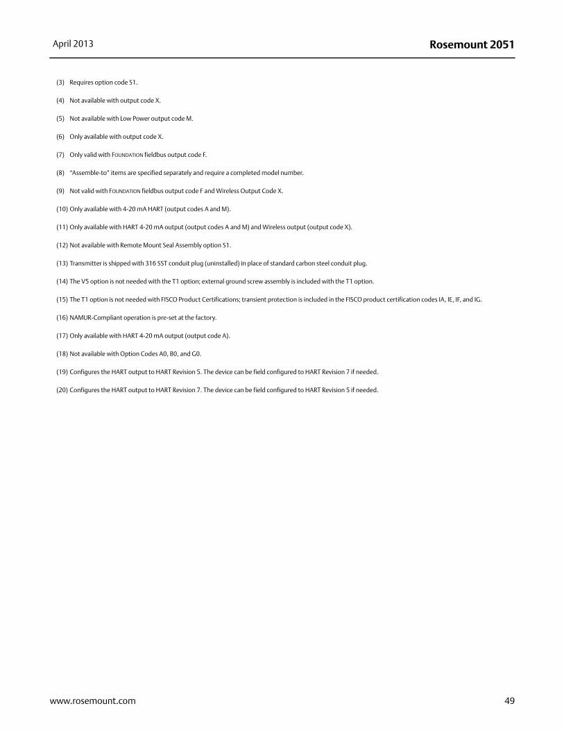
Rosemount 2051April 2013
49www.rosemount.com
(3) Requires option code S1.
(4) Not available with output code X.
(5) Not available with Low Power output code M.
(6) Only available with output code X.
(7) Only valid with FOUNDATION fieldbus output code F.
(8) “Assemble-to” items are specified separately and require a completed model number.
(9) Not valid with FOUNDATION fieldbus output code F and Wireless Output Code X.
(10) Only available with 4-20 mA HART (output codes A and M).
(11) Only available with HART 4-20 mA output (output codes A and M) and Wireless output (output code X).
(12) Not available with Remote Mount Seal Assembly option S1.
(13) Transmitter is shipped with 316 SST conduit plug (uninstalled) in place of standard carbon steel conduit plug.
(14) The V5 option is not needed with the T1 option; external ground screw assembly is included with the T1 option.
(15) The T1 option is not needed with FISCO Product Certifications; transient protection is included in the FISCO product certification codes IA, IE, IF, and IG.
(16) NAMUR-Compliant operation is pre-set at the factory.
(17) Only available with HART 4-20 mA output (output code A).
(18) Not available with Option Codes A0, B0, and G0.
(19) Configures the HART output to HART Revision 5. The device can be field configured to HART Revision 7 if needed.
(20) Configures the HART output to HART Revision 7. The device can be field configured to HART Revision 5 if needed.
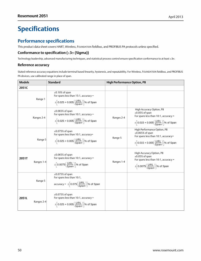
Rosemount 2051 April 2013
Specifications
Performance specificationsThis product data sheet covers HART, Wireless, FOUNDATION fieldbus, and PROFIBUS PA protocols unless specified.
Conformance to specification (±3 (Sigma))
Technology leadership, advanced manufacturing techniques, and statistical process control ensure specification conformance to at least ±3.
Reference accuracy
Stated reference accuracy equations include terminal based linearity, hysteresis, and repeatability. For Wireless, FOUNDATION fieldbus, and PROFIBUS
PA devices, use calibrated range in place of span.
Models Standard High Performance Option, P8
2051C
Range 1
±0.10% of spanFor spans less than 15:1, accuracy =
Ranges 2-4
±0.065% of spanFor spans less than 10:1, accuracy =
Ranges 2-4
High Accuracy Option, P8±0.05% of spanFor spans less than 10:1, accuracy =
Range 5
±0.075% of spanFor spans less than 10:1, accuracy=
Range 5
High Performance Option, P8±0.065% of spanFor spans less than 10:1, accuracy=
2051TRanges 1-4
±0.065% of spanFor spans less than 10:1, accuracy =
Ranges 1-4
High Accuracy Option, P8±0.05% of spanFor spans less than 10:1, accuracy =
Range 5
±0.075% of spanFor spans less than 10:1,
accuracy =
2051LRanges 2-4
±0.075% of spanFor spans less than 10:1, accuracy =
0.025 0.005+URLSpan--------------- % of Span
0.025 0.005+URLSpan--------------- % of Span
0.015 0.005+URLSpan--------------- % of Span
0.025 0.005+URLSpan--------------- % of Span
0.015 0.005+URLSpan--------------- % of Span
0.0075URLSpan--------------- % of Span
0.0075URLSpan--------------- % of Span
0.075URLSpan--------------- % of Span
0.025 0.005+URLSpan--------------- % of Span
50 www.rosemount.com
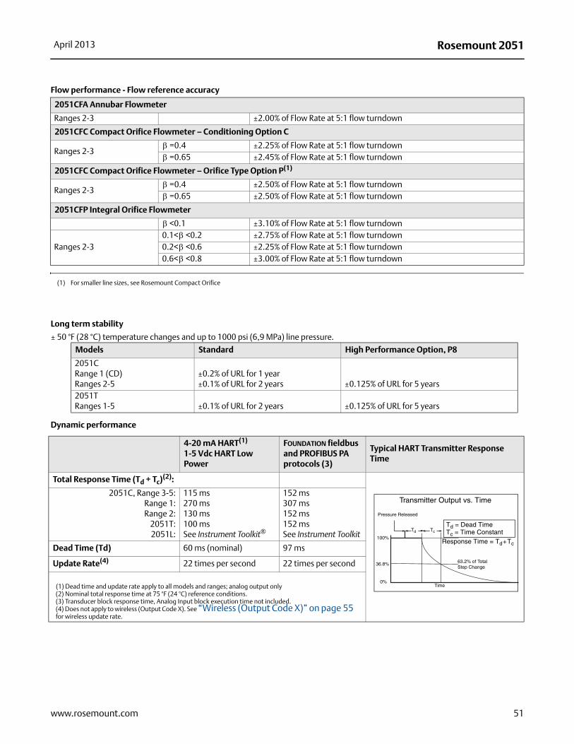
Rosemount 2051April 2013
Long term stability
± 50 °F (28 °C) temperature changes and up to 1000 psi (6,9 MPa) line pressure.
Dynamic performance
Flow performance - Flow reference accuracy
2051CFA Annubar Flowmeter
Ranges 2-3 ±2.00% of Flow Rate at 5:1 flow turndown
2051CFC Compact Orifice Flowmeter – Conditioning Option C
Ranges 2-3=0.4 ±2.25% of Flow Rate at 5:1 flow turndown=0.65 ±2.45% of Flow Rate at 5:1 flow turndown
2051CFC Compact Orifice Flowmeter – Orifice Type Option P(1)
Ranges 2-3=0.4 ±2.50% of Flow Rate at 5:1 flow turndown=0.65 ±2.50% of Flow Rate at 5:1 flow turndown
2051CFP Integral Orifice Flowmeter
<0.1 ±3.10% of Flow Rate at 5:1 flow turndown
Ranges 2-30.1< <0.2 ±2.75% of Flow Rate at 5:1 flow turndown0.2< <0.6 ±2.25% of Flow Rate at 5:1 flow turndown0.6< <0.8 ±3.00% of Flow Rate at 5:1 flow turndown
(1) For smaller line sizes, see Rosemount Compact Orifice
Models Standard High Performance Option, P8
2051CRange 1 (CD)Ranges 2-5
±0.2% of URL for 1 year±0.1% of URL for 2 years ±0.125% of URL for 5 years
2051TRanges 1-5 ±0.1% of URL for 2 years ±0.125% of URL for 5 years
4-20 mA HART(1)
1-5 Vdc HART Low Power
FOUNDATION fieldbus and PROFIBUS PA protocols (3)
Typical HART Transmitter Response Time
Total Response Time (Td + Tc)(2):
2051C, Range 3-5:Range 1:Range 2:
2051T:2051L:
115 ms270 ms 130 ms100 msSee Instrument Toolkit®
152 ms307 ms152 ms152 msSee Instrument Toolkit
Dead Time (Td) 60 ms (nominal) 97 ms
Update Rate(4) 22 times per second 22 times per second
(1) Dead time and update rate apply to all models and ranges; analog output only(2) Nominal total response time at 75 °F (24 °C) reference conditions. (3) Transducer block response time, Analog Input block execution time not included.(4) Does not apply to wireless (Output Code X). See “Wireless (Output Code X)” on page 55 for wireless update rate.
TcTd
Td = Dead TimeTc = Time Constant
Pressure Released
Response Time = Td+Tc
63.2% of TotalStep Change
Time0%
100%
36.8%
Transmitter Output vs. Time
51www.rosemount.com
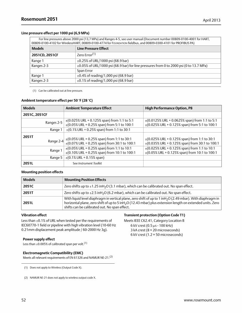
Rosemount 2051 April 2013
Line pressure effect per 1000 psi (6,9 MPa)
Ambient temperature effect per 50 °F (28 °C)
Mounting position effects
Vibration effect
Less than ±0.1% of URL when tested per the requirements of IEC60770-1 field or pipeline with high vibration level (10-60 Hz 0.21mm displacement peak amplitude / 60-2000 Hz 3g).
Transient protection (Option Code T1)
Meets IEEE C62.41, Category Location B6 kV crest (0.5 s - 100 kHz)3 kA crest (8 × 20 microseconds)6 kV crest (1.2 × 50 microseconds)
For line pressures above 2000 psi (13,7 MPa) and Ranges 4-5, see user manual (Document number 00809-0100-4001 for HART, 00809-0100-4102 for WirelessHART, 00809-0100-4774 for FOUNDATION fieldbus, and 00809-0300-4101 for PROFIBUS PA)
Models Line Pressure Effect
2051CD, 2051CF Zero Error(1)
Range 1 ±0.25% of URL/1000 psi (68.9 bar)Ranges 2-3 ±0.05% of URL/1000 psi (68.9 bar) for line pressures from 0 to 2000 psi (0 to 13.7 MPa)
Span ErrorRange 1 ±0.4% of reading/1,000 psi (68.9 bar)Ranges 2-3 ±0.1% of reading/1,000 psi (68.9 bar)
(1) Can be calibrated out at line pressure.
Models Ambient Temperature Effect High Performance Option, P8
2051C, 2051CF
Ranges 2-5±(0.025% URL + 0.125% span) from 1:1 to 5:1±(0.05% URL + 0.25% span) from 5:1 to 100:1
±(0.0125% URL + 0.0625% span) from 1:1 to 5:1±(0.025% URL + 0.125% span) from 5:1 to 100:1
Range 1 ±(0.1% URL + 0.25% span) from 1:1 to 30:1
2051TRange 2-4
±(0.05% URL + 0.25% span) from 1:1 to 30:1±(0.07% URL + 0.25% span) from 30:1 to 100:1
±(0.025% URL + 0.125% span) from 1:1 to 30:1±(0.035% URL + 0.125% span) from 30:1 to 100:1
Range 1±(0.05% URL + 0.25% span) from 1:1 to 10:1±(0.10% URL + 0.25% span) from 10:1 to 100:1
±(0.025% URL + 0.125% span) from 1:1 to 10:1±(0.05% URL + 0.125% span) from 10:1 to 100:1
Range 5 ±(0.1% URL + 0.15% span)
2051L See Instrument Toolkit
Models Mounting Position Effects
2051C Zero shifts up to ±1.25 inH2O (3.1 mbar), which can be calibrated out. No span effect.
2051T Zero shifts up to ±2.5 inH2O (6.2 mbar), which can be calibrated out. No span effect.
2051LWith liquid level diaphragm in vertical plane, zero shift of up to 1 inH2O (2.49 mbar). With diaphragm in horizontal plane, zero shift of up to 5 inH2O (12.43 mbar) plus extension length on extended units. Zero shifts can be calibrated out. No span effect.
Power supply effectLess than ±0.005% of calibrated span per volt.(1)
(1) Does not apply to Wireless (Output Code X).
Electromagnetic Compatibility (EMC)Meets all relevant requirements of EN 61326 and NAMUR NE-21.(2)
(2) NAMUR NE-21 does not apply to wireless output code X.
52 www.rosemount.com
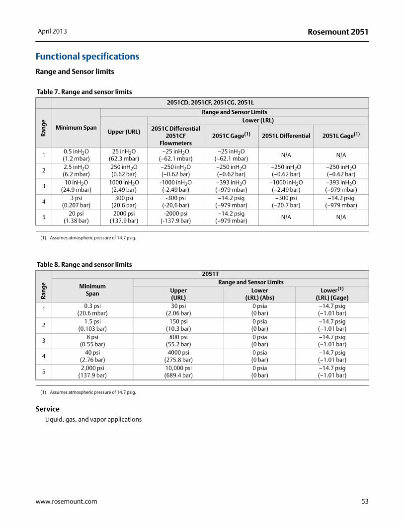
Rosemount 2051April 2013
Functional specifications
Range and Sensor limits
ServiceLiquid, gas, and vapor applications
Table 7. Range and sensor limits
2051CD, 2051CF, 2051CG, 2051L
Ran
ge
Minimum Span
Range and Sensor Limits
Upper (URL)
Lower (LRL) 2051C Differential
2051CF Flowmeters
2051C Gage(1) 2051L Differential 2051L Gage(1)
10.5 inH2O(1.2 mbar)
25 inH2O(62.3 mbar)
–25 inH2O(–62.1 mbar)
–25 inH2O(–62.1 mbar)
N/A N/A
22.5 inH2O (6.2 mbar)
250 inH2O(0.62 bar)
–250 inH2O(–0.62 bar)
–250 inH2O(–0.62 bar)
–250 inH2O(–0.62 bar)
–250 inH2O(–0.62 bar)
310 inH2O
(24.9 mbar)1000 inH2O
(2.49 bar)-1000 inH2O
(-2.49 bar)–393 inH2O (–979 mbar)
–1000 inH2O (–2.49 bar)
–393 inH2O (–979 mbar)
43 psi
(0.207 bar)300 psi
(20.6 bar)-300 psi
(-20,6 bar)–14.2 psig
(–979 mbar)–300 psi
(–20.7 bar)–14.2 psig
(–979 mbar)
520 psi
(1.38 bar)2000 psi
(137.9 bar)-2000 psi
(-137.9 bar)–14.2 psig
(–979 mbar)N/A N/A
(1) Assumes atmospheric pressure of 14.7 psig.
Table 8. Range and sensor limits
Ran
ge
2051T
Minimum Span
Range and Sensor LimitsUpper(URL)
Lower (LRL) (Abs)
Lower(1)
(LRL) (Gage)
10.3 psi
(20.6 mbar)30 psi
(2.06 bar)0 psia(0 bar)
–14.7 psig(–1.01 bar)
21.5 psi
(0.103 bar)150 psi
(10.3 bar)0 psia(0 bar)
–14.7 psig(–1.01 bar)
38 psi
(0.55 bar)800 psi
(55.2 bar)0 psia(0 bar)
–14.7 psig(–1.01 bar)
440 psi
(2.76 bar)4000 psi
(275.8 bar)0 psia(0 bar)
–14.7 psig(–1.01 bar)
52,000 psi
(137.9 bar) 10,000 psi(689.4 bar)
0 psia(0 bar)
–14.7 psig(–1.01 bar)
(1) Assumes atmospheric pressure of 14.7 psig.
53www.rosemount.com
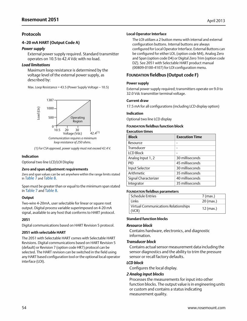
Rosemount 2051 April 2013
54 www.rosemount.com
Protocols
4–20 mA HART (Output Code A)
Power supplyExternal power supply required. Standard transmitter operates on 10.5 to 42.4 Vdc with no load.
Load limitations Maximum loop resistance is determined by the voltage level of the external power supply, as described by:
Indication
Optional two line LCD/LOI Display
Zero and span adjustment requirementsZero and span values can be set anywhere within the range limits stated in Table 7 and Table 8.
Span must be greater than or equal to the minimum span stated in Table 7 and Table 8.
Output
Two-wire 4-20mA, user selectable for linear or square root output. Digital process variable superimposed on 4-20 mA signal, available to any host that conforms to HART protocol.
2051
Digital communications based on HART Revision 5 protocol.
2051 with selectable HART
The 2051 with Selectable HART comes with Selectable HART Revisions. Digital communications based on HART Revision 5 (default) or Revision 7 (option code HR7) protocol can be selected. The HART revision can be switched in the field using any HART based configuration tool or the optional local operator interface (LOI).
Local Operator Interface
The LOI utilizes a 2 button menu with internal and external configuration buttons. Internal buttons are always configured for Local Operator Interface. External Buttons can be configured for either LOI, (option code M4), Analog Zero and Span (option code D4) or Digital Zero Trim (option code DZ). See 2051 with Selectable HART product manual (00809-0100-4107) for LOI configuration menu.
FOUNDATION fieldbus (Output code F)
Power supply
External power supply required; transmitters operate on 9.0 to 32.0 Vdc transmitter terminal voltage.
Current draw
17.5 mA for all configurations (including LCD display option)
Indication
Optional two line LCD display
FOUNDATION fieldbus function block Execution times
FOUNDATION fieldbus parameters
Standard function blocks
Resource blockContains hardware, electronics, and diagnostic information.
Transducer blockContains actual sensor measurement data including the sensor diagnostics and the ability to trim the pressure sensor or recall factory defaults.
LCD blockConfigures the local display.
2 Analog input blocksProcesses the measurements for input into other function blocks. The output value is in engineering units or custom and contains a status indicating measurement quality.
Communication requires a minimum loop resistance of 250 ohms.
(1) For CSA approval, power supply must not exceed 42.4 V.
Max. Loop Resistance = 43.5 (Power Supply Voltage – 10.5)
Voltage (Vdc)
Load
(s)
OperatingRegion
1387
1000
500
010.5 20 30
42.4(1)
Block Execution Time
Resource -Transducer -LCD Block -Analog Input 1, 2 30 millisecondsPID 45 millisecondsInput Selector 30 millisecondsArithmetic 35 millisecondsSignal Characterizer 40 millisecondsIntegrator 35 milliseconds
Schedule Entries 7 (max.)Links 20 (max.)Virtual Communications Relationships (VCR)
12 (max.)
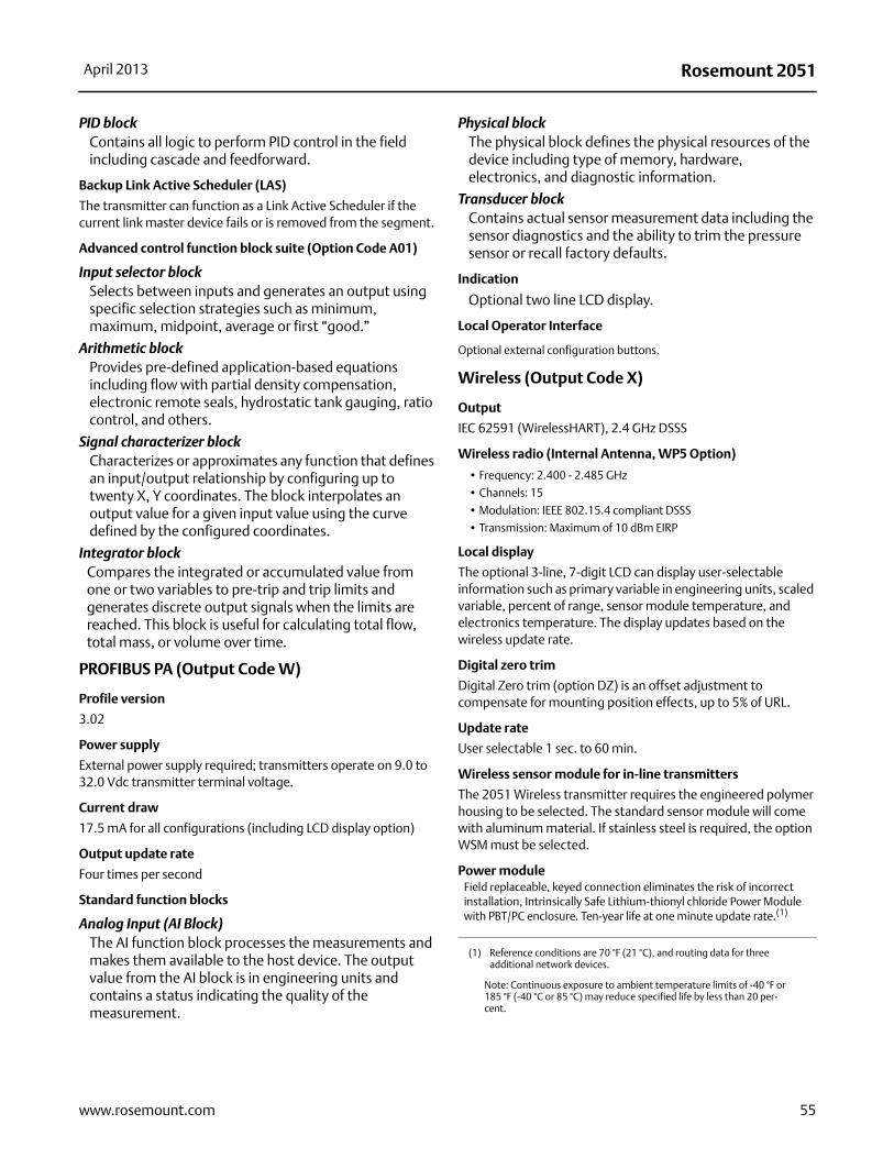
Rosemount 2051April 2013
PID block Contains all logic to perform PID control in the field including cascade and feedforward.
Backup Link Active Scheduler (LAS)
The transmitter can function as a Link Active Scheduler if the current link master device fails or is removed from the segment.
Advanced control function block suite (Option Code A01)
Input selector blockSelects between inputs and generates an output using specific selection strategies such as minimum, maximum, midpoint, average or first “good.”
Arithmetic blockProvides pre-defined application-based equations including flow with partial density compensation, electronic remote seals, hydrostatic tank gauging, ratio control, and others.
Signal characterizer blockCharacterizes or approximates any function that defines an input/output relationship by configuring up to twenty X, Y coordinates. The block interpolates an output value for a given input value using the curve defined by the configured coordinates.
Integrator blockCompares the integrated or accumulated value from one or two variables to pre-trip and trip limits and generates discrete output signals when the limits are reached. This block is useful for calculating total flow, total mass, or volume over time.
PROFIBUS PA (Output Code W)
Profile version
3.02
Power supply
External power supply required; transmitters operate on 9.0 to 32.0 Vdc transmitter terminal voltage.
Current draw
17.5 mA for all configurations (including LCD display option)
Output update rate
Four times per second
Standard function blocks
Analog Input (AI Block)The AI function block processes the measurements and makes them available to the host device. The output value from the AI block is in engineering units and contains a status indicating the quality of the measurement.
Physical blockThe physical block defines the physical resources of the device including type of memory, hardware, electronics, and diagnostic information.
Transducer blockContains actual sensor measurement data including the sensor diagnostics and the ability to trim the pressure sensor or recall factory defaults.
Indication
Optional two line LCD display.
Local Operator Interface
Optional external configuration buttons.
Wireless (Output Code X)
Output
IEC 62591 (WirelessHART), 2.4 GHz DSSS
Wireless radio (Internal Antenna, WP5 Option)
• Frequency: 2.400 - 2.485 GHz
• Channels: 15
• Modulation: IEEE 802.15.4 compliant DSSS
• Transmission: Maximum of 10 dBm EIRP
Local display
The optional 3-line, 7-digit LCD can display user-selectable information such as primary variable in engineering units, scaled variable, percent of range, sensor module temperature, and electronics temperature. The display updates based on the wireless update rate.
Digital zero trim
Digital Zero trim (option DZ) is an offset adjustment to compensate for mounting position effects, up to 5% of URL.
Update rate
User selectable 1 sec. to 60 min.
Wireless sensor module for in-line transmitters
The 2051 Wireless transmitter requires the engineered polymer housing to be selected. The standard sensor module will come with aluminum material. If stainless steel is required, the option WSM must be selected.
Power moduleField replaceable, keyed connection eliminates the risk of incorrect installation, Intrinsically Safe Lithium-thionyl chloride Power Module with PBT/PC enclosure. Ten-year life at one minute update rate.(1)
(1) Reference conditions are 70 °F (21 °C), and routing data for three additional network devices.
Note: Continuous exposure to ambient temperature limits of -40 °F or 185 °F (-40 °C or 85 °C) may reduce specified life by less than 20 per-cent.
55www.rosemount.com
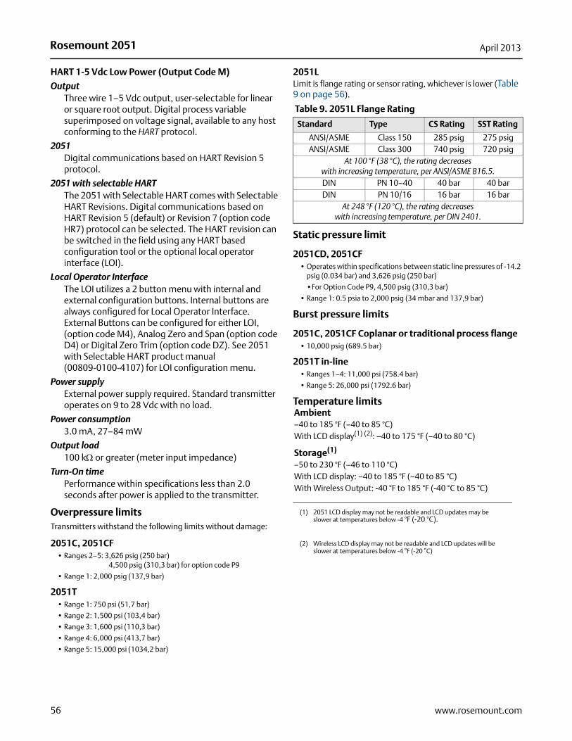
Rosemount 2051 April 2013
56 www.rosemount.com
HART 1-5 Vdc Low Power (Output Code M)
OutputThree wire 1–5 Vdc output, user-selectable for linear or square root output. Digital process variable superimposed on voltage signal, available to any host conforming to the HART protocol.
2051Digital communications based on HART Revision 5 protocol.
2051 with selectable HARTThe 2051 with Selectable HART comes with Selectable HART Revisions. Digital communications based on HART Revision 5 (default) or Revision 7 (option code HR7) protocol can be selected. The HART revision can be switched in the field using any HART based configuration tool or the optional local operator interface (LOI).
Local Operator InterfaceThe LOI utilizes a 2 button menu with internal and external configuration buttons. Internal buttons are always configured for Local Operator Interface. External Buttons can be configured for either LOI, (option code M4), Analog Zero and Span (option code D4) or Digital Zero Trim (option code DZ). See 2051 with Selectable HART product manual (00809-0100-4107) for LOI configuration menu.
Power supplyExternal power supply required. Standard transmitter operates on 9 to 28 Vdc with no load.
Power consumption3.0 mA, 27–84 mW
Output load100 k or greater (meter input impedance)
Turn-On timePerformance within specifications less than 2.0 seconds after power is applied to the transmitter.
Overpressure limitsTransmitters withstand the following limits without damage:
2051C, 2051CF• Ranges 2–5: 3,626 psig (250 bar)
4,500 psig (310,3 bar) for option code P9
• Range 1: 2,000 psig (137,9 bar)
2051T• Range 1: 750 psi (51,7 bar)
• Range 2: 1,500 psi (103,4 bar)
• Range 3: 1,600 psi (110,3 bar)
• Range 4: 6,000 psi (413,7 bar)
• Range 5: 15,000 psi (1034,2 bar)
2051LLimit is flange rating or sensor rating, whichever is lower (Table 9 on page 56).
Static pressure limit
2051CD, 2051CF• Operates within specifications between static line pressures of -14.2
psig (0.034 bar) and 3,626 psig (250 bar)
•For Option Code P9, 4,500 psig (310,3 bar)
• Range 1: 0.5 psia to 2,000 psig (34 mbar and 137,9 bar)
Burst pressure limits
2051C, 2051CF Coplanar or traditional process flange• 10,000 psig (689.5 bar)
2051T in-line• Ranges 1–4: 11,000 psi (758.4 bar)
• Range 5: 26,000 psi (1792.6 bar)
Temperature limits
Table 9. 2051L Flange Rating
Standard Type CS Rating SST Rating
ANSI/ASME Class 150 285 psig 275 psigANSI/ASME Class 300 740 psig 720 psig
At 100 °F (38 °C), the rating decreaseswith increasing temperature, per ANSI/ASME B16.5.DIN PN 10–40 40 bar 40 barDIN PN 10/16 16 bar 16 bar
At 248 °F (120 °C), the rating decreases with increasing temperature, per DIN 2401.
Ambient–40 to 185 °F (–40 to 85 °C)With LCD display(1) (2): –40 to 175 °F (–40 to 80 °C)
Storage(1)
–50 to 230 °F (–46 to 110 °C)With LCD display: –40 to 185 °F (–40 to 85 °C)With Wireless Output: -40 °F to 185 °F (-40 °C to 85 °C)
(1) 2051 LCD display may not be readable and LCD updates may be slower at temperatures below -4 °F (-20 °C).
(2) Wireless LCD display may not be readable and LCD updates will be slower at temperatures below -4 °F (-20 °C)
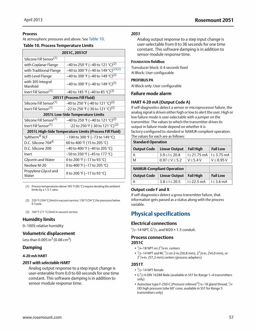
Rosemount 2051April 2013
Process At atmospheric pressures and above. See Table 10.
Humidity limits0–100% relative humidity
Volumetric displacementLess than 0.005 in3 (0.08 cm3)
Damping
4-20 mA HART
2051 with selectable HARTAnalog output response to a step input change is user-enterable from 0.0 to 60 seconds for one time constant. This software damping is in addition to sensor module response time.
2051Analog output response to a step input change is user-selectable from 0 to 36 seconds for one time constant. This software damping is in addition to sensor module response time.
FOUNDATION fieldbus
Transducer block: 0.4 seconds fixedAI Block: User configurable
PROFIBUS PA
AI Block only: User configurable
Failure mode alarm
HART 4-20 mA (Output Code A)If self-diagnostics detect a sensor or microprocessor failure, the analog signal is driven either high or low to alert the user. High or low failure mode is user-selectable with a jumper on the transmitter. The values to which the transmitter drives its output in failure mode depend on whether it is factory-configured to standard or NAMUR-compliant operation. The values for each are as follows:
Output code F and XIf self-diagnostics detect a gross transmitter failure, that information gets passed as a status along with the process variable.
Physical specifications
Electrical connections1/2–14 NPT, G1/2, and M20 × 1.5 conduit.
Process connections2051C
• 1/4–18 NPT on 21/8-in. centers
• 1/2–14 NPT and RC 1/2 on 2-in.(50,8 mm), 21/8-in. (54,0 mm), or 21/4-in. (57,2 mm) centers (process adapters)
2051T• 1/2–14 NPT female
• G1/2 A DIN 16288 Male (available in SST for Range 1–4 transmitters only)
• Autoclave type F-250-C (Pressure relieved 9/16–18 gland thread; 1/4 OD high pressure tube 60° cone; available in SST for Range 5 transmitters only)
Table 10. Process Temperature Limits
2051C, 2051CF
Silicone Fill Sensor(1)
(1) Process temperatures above 185 °F (85 °C) require derating the ambient limits by a 1.5:1 ratio.
with Coplanar Flange –40 to 250 °F (–40 to 121 °C)(2)
(2) 220 °F (104 °C) limit in vacuum service; 130 °F (54 °C) for pressures below 0.5 psia.
with Traditional Flange –40 to 300 °F (–40 to 149 °C)(2)(3)
with Level Flange –40 to 300 °F (–40 to 149 °C)(2)
with 305 Integral Manifold
–40 to 300 °F (–40 to 149 °C)(2)
Inert Fill Sensor(1) –40 to 185 °F (–40 to 85 °C)(3)
(3) 160 °F (71 °C) limit in vacuum service.
2051T (Process Fill Fluid)
Silicone Fill Sensor(1) -40 to 250 °F (-40 to 121 °C)(2)
Inert Fill Sensor(1) -22 to 250 °F (-30 to 121 °C)(2)
2051L Low-Side Temperature Limits
Silicone Fill Sensor(1) –40 to 250 °F (–40 to 121 °C)(2)
Inert Fill Sensor(1) -22 to 250 °F (-30 to 121 °C) (2)
2051L High-Side Temperature Limits (Process Fill Fluid)
Syltherm® XLT –100 to 300 °F (–73 to 149 °C)
D.C. Silicone 704® 60 to 400 °F (15 to 205 °C)
D.C. Silicone 200 –40 to 400 °F (–40 to 205 °C)
Inert –50 to 350 °F (–45 to 177 °C)
Glycerin and Water 0 to 200 °F (–17 to 93 °C)
Neobee M-20 0 to 400 °F (–17 to 205 °C)
Propylene Glycol and Water
0 to 200 °F (–17 to 93 °C)
Standard Operation
Output Code Linear Output Fail High Fail Low
A 3.9 I 20.8 I21.75 mA I 3.75 mAM 0.97 V 5.2 V5.4 V V 0.95 V
NAMUR-Compliant Operation
Output Code Linear Output Fail High Fail Low
A 3.8 I 20.5 I22.5 mA I 3.6 mA
57www.rosemount.com

Rosemount 2051 April 2013
2051L• High pressure side: 2-in.(50,8 mm), 3-in. (72 mm), or 4-in. (102
mm), ASME B 16.5 (ANSI) Class 150 or 300 flange; 50, 80, or 100 mm, DIN 2501 PN 40 or 10/16 flange
• Low pressure side: 1/4–18 NPT on flange, 1/2–14 NPT on process adapter
2051CF • For 2051CFA wetted parts, see 00813-01000-4485 in the 485
section
• For 2051CFC wetted parts, see 00813-01000-4485 in the 405 section
• For 2051CFP wetted parts, see 00813-01000-4485 in the 1195 section
2051C process wetted parts
Drain/Vent Valves316 SST or Alloy C-276
Process flanges and adaptersPlated carbon steel, SST CF-8M (cast version of 316 SST, material per ASTM-A743), or CW2M (cast version of Alloy C)
Wetted O-ringsGlass-filled PTFE or Graphite-filled PTFE
Process isolating diaphragms316L SST, Alloy C-276, or Tantalum
2051T process wetted parts
Process connections• 316L SST or Alloy C-276
Process Isolating diaphragms • 316L SST or Alloy C-276
2051L Process wetted parts
Flanged process connection (Transmitter high side)
Process diaphragms, Including process gasket surface•316L SST, Alloy C-276, or Tantalum
Extension•CF-3M (Cast version of 316L SST, material per ASTM-A743), or
Cast C-276. Fits schedule 40 and 80 pipe.
Mounting flange•Zinc-cobalt plated CS or SST
Reference process connection (Transmitter low side)
Isolating diaphragms•316L SST or Alloy C-276
Reference flange and adapter•CF-8M (Cast version of 316 SST, material per ASTM-A743)
Non-wetted parts for 2051C/T/L
Electronics housingLow-copper aluminum or CF-8M (Cast version of 316 SST). Enclosure Type 4X, IP 65, IP 66, IP68Housing Material Code P: PBT/PC with NEMA 4X and IP66/67/68
Paint for aluminum housingPolyurethane
Coplanar sensor module housingCF-3M (Cast version of 316L SST)
BoltsASTM A449, Type 1 (zinc-cobalt plated carbon steel)ASTM F593G, Condition CW1 (Austenitic 316 SST)ASTM A193, Grade B7M (zinc plated alloy steel)Alloy K-500
Sensor module fill fluidSilicone or inert halocarbon In-Line series uses Fluorinert® FC-43
Process fill fluid (2051L only)Syltherm XLT, D.C. Silicone 704, D.C. Silicone 200, inert, glycerin and water, Neobee M-20, or propylene glycol and water
Cover O-ringsBuna-NSilicone (for wireless option code X)
Power moduleField replaceable, keyed connection eliminates the risk of incorrect installation, Intrinsically Safe Lithium-thionyl chloride Power Module with PBT enclosure.
Shipping weights
Table 11. Transmitter weights without Options(1)
(1) Transmitter weights include the sensor module and housing only (aluminum for standard 2051 and polymer for wireless).
Transmitter Standard 2051 In lb. (kg) Wireless In lb. (kg)
2051C 4.9 (2.2) 3.9 (1,8)2051L Table 12 below Table 12 below2051T 3.1 (1.4) 1.9 (0,86)
58 www.rosemount.com
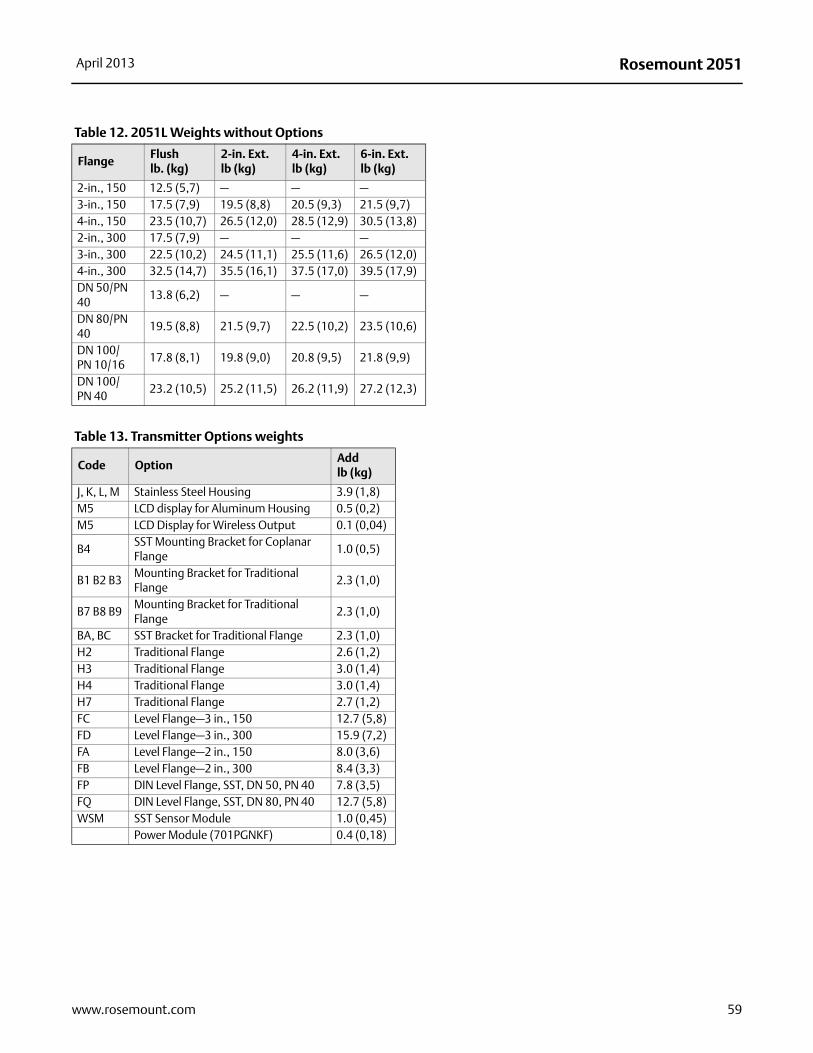
Rosemount 2051April 2013
Table 12. 2051L Weights without Options
FlangeFlushlb. (kg)
2-in. Ext.lb (kg)
4-in. Ext.lb (kg)
6-in. Ext.lb (kg)
2-in., 150 12.5 (5,7) — — —3-in., 150 17.5 (7,9) 19.5 (8,8) 20.5 (9,3) 21.5 (9,7)4-in., 150 23.5 (10,7) 26.5 (12,0) 28.5 (12,9) 30.5 (13,8)2-in., 300 17.5 (7,9) — — —3-in., 300 22.5 (10,2) 24.5 (11,1) 25.5 (11,6) 26.5 (12,0)4-in., 300 32.5 (14,7) 35.5 (16,1) 37.5 (17,0) 39.5 (17,9)DN 50/PN 40
13.8 (6,2) — — —
DN 80/PN 40
19.5 (8,8) 21.5 (9,7) 22.5 (10,2) 23.5 (10,6)
DN 100/PN 10/16
17.8 (8,1) 19.8 (9,0) 20.8 (9,5) 21.8 (9,9)
DN 100/PN 40
23.2 (10,5) 25.2 (11,5) 26.2 (11,9) 27.2 (12,3)
Table 13. Transmitter Options weights
Code OptionAddlb (kg)
J, K, L, M Stainless Steel Housing 3.9 (1,8)M5 LCD display for Aluminum Housing 0.5 (0,2)M5 LCD Display for Wireless Output 0.1 (0,04)
B4SST Mounting Bracket for Coplanar Flange
1.0 (0,5)
B1 B2 B3Mounting Bracket for Traditional Flange
2.3 (1,0)
B7 B8 B9Mounting Bracket for Traditional Flange
2.3 (1,0)
BA, BC SST Bracket for Traditional Flange 2.3 (1,0)H2 Traditional Flange 2.6 (1,2)H3 Traditional Flange 3.0 (1,4)H4 Traditional Flange 3.0 (1,4)H7 Traditional Flange 2.7 (1,2)FC Level Flange—3 in., 150 12.7 (5,8)FD Level Flange—3 in., 300 15.9 (7,2)FA Level Flange—2 in., 150 8.0 (3,6)FB Level Flange—2 in., 300 8.4 (3,3)FP DIN Level Flange, SST, DN 50, PN 40 7.8 (3,5)FQ DIN Level Flange, SST, DN 80, PN 40 12.7 (5,8)WSM SST Sensor Module 1.0 (0,45)
Power Module (701PGNKF) 0.4 (0,18)
59www.rosemount.com
Rosemount 2051 April 2013
60 www.rosemount.com
Product certifications
Approved manufacturing locationsRosemount Inc. — Chanhassen, Minnesota USAEmerson Process Management GmbH & Co. — Wessling, GermanyEmerson Process Management Asia Pacific Private Limited — SingaporeBeijing Rosemount Far East Instrument Co., LTD — Beijing, ChinaEmerson Process Management LTDA — Sorocaba, BrazilEmerson Process Management (India) Pvt. Ltd — Daman, India
European directive informationThe EC declaration of conformity for all applicable European directives for this product can be found on the Rosemount website at www.rosemount.com. A hard copy may be obtained by contacting an Emerson Process Management representative.
Ordinary location certification for Factory MutualAs standard, the transmitter has been examined and tested to determine that the design meets basic electrical, mechanical, and fire protection requirements by FM, a nationally recognized testing laboratory (NRTL) as accredited by the Federal Occupational Safety and Health Administration (OSHA).
HART Protocol
Hazardous locations certifications
North American certifications
FM Approvals
E5 Explosion-Proof and Dust-Ignition-ProofCertificate No: 3032938Applicable Standards: FM Class 3600 – 1998, FM Class 3615 – 2006, FM Class 3810 – 2005, ANSI/NEMA 250 – 1991, ANSI/IEC 60529 – 2004Markings: Explosion-Proof for Class I, Division 1, Groups B, C, and DDust-Ignition-Proof for Class II, Division 1, Groups E, F, G; and Class III, Division 1.T5 (Ta= -50 °C to +85 °C), Factory Sealed, Enclosure Type 4X
I5 Intrinsically-Safe and Non-incendiveCertificate No: 3033457Applicable Standards: FM Class 3600 – 1998, FM Class 3610 – 2007, FM Class 3611 – 2004, FM Class 3810 – 2005 Markings: Intrinsically Safe for use in Class I, Division 1, Groups A, B, C, and D; Class II, Divisions 1, Groups E, F, and G; Class III, Division 1; Class I, Zone 0, AEx ia IIC; Nonincendive for use in Class I, Division 2, Groups A, B, C and D; in accordance with Control Drawing 02051-1009T4 (-50 °C to +70 °C) Enclosure Type 4XTemperature Code:T4 (Ta = -50 °C to +70 °C),Enclosure Type 4XFor input parameters see control drawing 02051-1009.
Special Conditions for Safe Use:
1. The Model 2051 transmitter housing contains aluminum and is considered a potential risk of ignition by impact or friction. Care must be taken into account during installation and use to prevent impact and friction.
2. The Model 2051 transmitter with the transient terminal block (Option code T1) will not pass the 500Vrms dielectric strength test and this must be taken into account during installation.
Canadian Standards Association (CSA)
All CSA hazardous approved transmitters are certified per ANSI/ISA
12.27.01-2003.
E6 Explosion-Proof, Dust Ignition ProofCertificate No: 2041384Applicable Standards: CSA Std. C22.2 No. 142 - M1987, CSA Std. C22.2 No. 30 - M1986, CSA Std. C22.2 No. 213 - M1987, CAN/CSA-E60079-0:07,CAN/CSA-E60079-1:07Markings: Explosion-Proof for Class I, Division 1, Groups B, C, and D. Dust-Ignitions Proof for Class II and Class III, Division 1, Groups E, F, and G. Suitable for Class I, Division 2, Groups A, B, C, and D for indoor and outdoor hazardous locations. Class I Zone 1 Ex d IIC T5. Enclosure type 4X, factory sealed. Single Seal.
I6 Intrinsically SafeCertificate no.: 2041384Applicable Standards: CSA Std. C22.2 No. 142 - M1987, CSA Std. C22.2 No. 213 - M1987, CSA Std. C22.2 No. 157 - 92, CSA Std. C22.2 No. 213 - M1987, ANSI/ISA 12.27.01 - 2003, CAN/CSA-E60079-0:07, CAN/CSA-E60079-11:02Markings: Intrinsically safe for Class I, Division 1, Groups A, B, C, and D when connected in accordance with Rosemount drawings 02051-1008. Temperature code T3C. Class I Zone 1 Ex ia IIC T3C. Single Seal. Enclosure Type 4X.
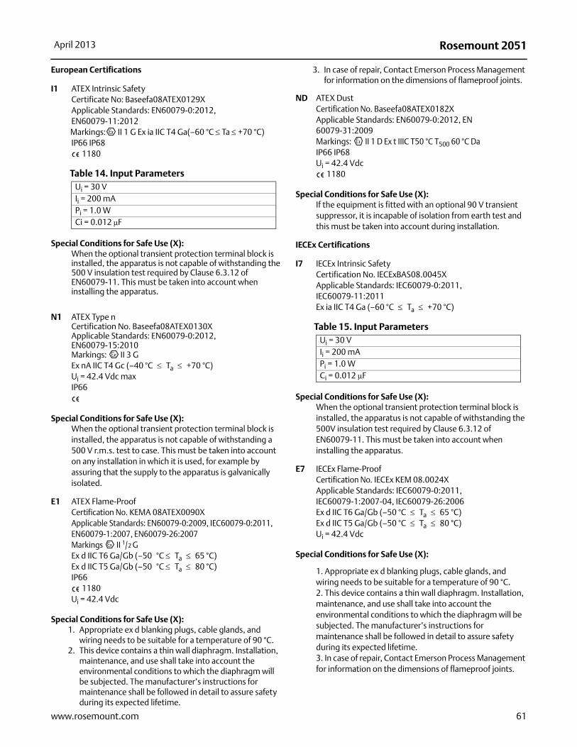
Rosemount 2051April 2013
61www.rosemount.com
European Certifications
I1 ATEX Intrinsic SafetyCertificate No: Baseefa08ATEX0129XApplicable Standards: EN60079-0:2012, EN60079-11:2012Markings: II 1 G Ex ia IIC T4 Ga(–60 °C Ta +70 °C) IP66 IP68
1180
Special Conditions for Safe Use (X): When the optional transient protection terminal block is installed, the apparatus is not capable of withstanding the 500 V insulation test required by Clause 6.3.12 of EN60079-11. This must be taken into account when installing the apparatus.
N1 ATEX Type nCertification No. Baseefa08ATEX0130X Applicable Standards: EN60079-0:2012, EN60079-15:2010Markings: II 3 GEx nA IIC T4 Gc (–40 °C Ta +70 °C)Ui = 42.4 Vdc maxIP66
Special Conditions for Safe Use (X): When the optional transient protection terminal block is installed, the apparatus is not capable of withstanding a 500 V r.m.s. test to case. This must be taken into account on any installation in which it is used, for example by assuring that the supply to the apparatus is galvanically isolated.
E1 ATEX Flame-ProofCertification No. KEMA 08ATEX0090XApplicable Standards: EN60079-0:2009, IEC60079-0:2011, EN60079-1:2007, EN60079-26:2007Markings II 1/2 G Ex d IIC T6 Ga/Gb (–50 °C Ta 65 °C)Ex d IIC T5 Ga/Gb (–50 °C Ta 80 °C)IP66
1180Ui = 42.4 Vdc
Special Conditions for Safe Use (X): 1. Appropriate ex d blanking plugs, cable glands, and
wiring needs to be suitable for a temperature of 90 °C.2. This device contains a thin wall diaphragm. Installation,
maintenance, and use shall take into account the environmental conditions to which the diaphragm will be subjected. The manufacturer’s instructions for maintenance shall be followed in detail to assure safety during its expected lifetime.
3. In case of repair, Contact Emerson Process Management for information on the dimensions of flameproof joints.
ND ATEX DustCertification No. Baseefa08ATEX0182XApplicable Standards: EN60079-0:2012, EN 60079-31:2009Markings: II 1 D Ex t IIIC T50 °C T500 60 °C DaIP66 IP68Ui = 42.4 Vdc
1180
Special Conditions for Safe Use (X): If the equipment is fitted with an optional 90 V transient suppressor, it is incapable of isolation from earth test and this must be taken into account during installation.
IECEx Certifications
I7 IECEx Intrinsic Safety Certification No. IECExBAS08.0045XApplicable Standards: IEC60079-0:2011, IEC60079-11:2011Ex ia IIC T4 Ga (–60 °C Ta +70 °C)
Special Conditions for Safe Use (X): When the optional transient protection terminal block is installed, the apparatus is not capable of withstanding the 500V insulation test required by Clause 6.3.12 of EN60079-11. This must be taken into account when installing the apparatus.
E7 IECEx Flame-ProofCertification No. IECEx KEM 08.0024XApplicable Standards: IEC60079-0:2011, IEC60079-1:2007-04, IEC60079-26:2006Ex d IIC T6 Ga/Gb (–50 °C Ta 65 °C)Ex d IIC T5 Ga/Gb (–50 °C Ta 80 °C)Ui = 42.4 Vdc
Special Conditions for Safe Use (X):
1. Appropriate ex d blanking plugs, cable glands, and wiring needs to be suitable for a temperature of 90 °C.2. This device contains a thin wall diaphragm. Installation, maintenance, and use shall take into account the environmental conditions to which the diaphragm will be subjected. The manufacturer’s instructions for maintenance shall be followed in detail to assure safety during its expected lifetime.3. In case of repair, Contact Emerson Process Management for information on the dimensions of flameproof joints.
Table 14. Input ParametersUi = 30 VIi = 200 mAPi = 1.0 W Ci = 0.012 μF
Table 15. Input ParametersUi = 30 VIi = 200 mAPi = 1.0 W Ci = 0.012 μF
Rosemount 2051 April 2013
N7 IECEx Type 'n'Certification No. IECExBAS08.0046XApplicable Standards: IEC60079-0: 2011, IEC60079-15: 2010Ex nA IIC T4 Gc (–40 °C Ta +70 °C)Ui = 42.4 Vdc max
Special Conditions for Safe Use (X):
When the optional transient protection terminal block is installed, the apparatus is not capable of withstanding a 500 V r.m.s. test to case. This must be taken into account on any installation in which it is used, for example by assuring that the supply to the apparatus is galvanically isolated.
TIIS Certifications
E4 TIIS Flame-ProofEx d IIC T6
Inmetro Certifications
E3 Flame-ProofNEPSI Certificate No: GYJ101321XApplicable standards: GB3836.1-2000, GB3836.2-2000Markings: Ex d II C T5/T6T6 = -50 °C Tamb 80 °CT5 = -50 °C Tamb 65 °C
I3 Intrinsic SafetyCertificate No: GYJ101320XApplicable Standards: GB3836.1-2000, GB3836.4-2000Markings: Ex ia IIC T4T4: -60 °C Tamb 70 °C
China (NEPSI) Certifications
E3 Flame-ProofEx d IIC T5/T6
I3 Intrinsic SafetyEx ia IIC T4
CCOE Certifications
IW Intrinsic SafetyEx ia IIC T4
EW Flame-ProofEx d IIC T5
Combinations of Certifications
Stainless steel certification tag is provided when optional approval is
specified. Once a device labeled with multiple approval types is
installed, it should not be reinstalled using any other approval types.
Permanently mark the approval label to distinguish it from unused
approval types.
K1 E1, I1, N1, and ND combination
K2 E2 and I2 combination
K5 E5 and I5 combination
K6 I6 and E6 combination
K7 E7, I7, and N7 combination
KA E1, I1, E6, and I6 combination
KB E5, I5, E6, and I6 combination
KC E1, I1, E5, and I5 combination
KD E1, I1, E5, I5, E6, and I6 combination
62 www.rosemount.com
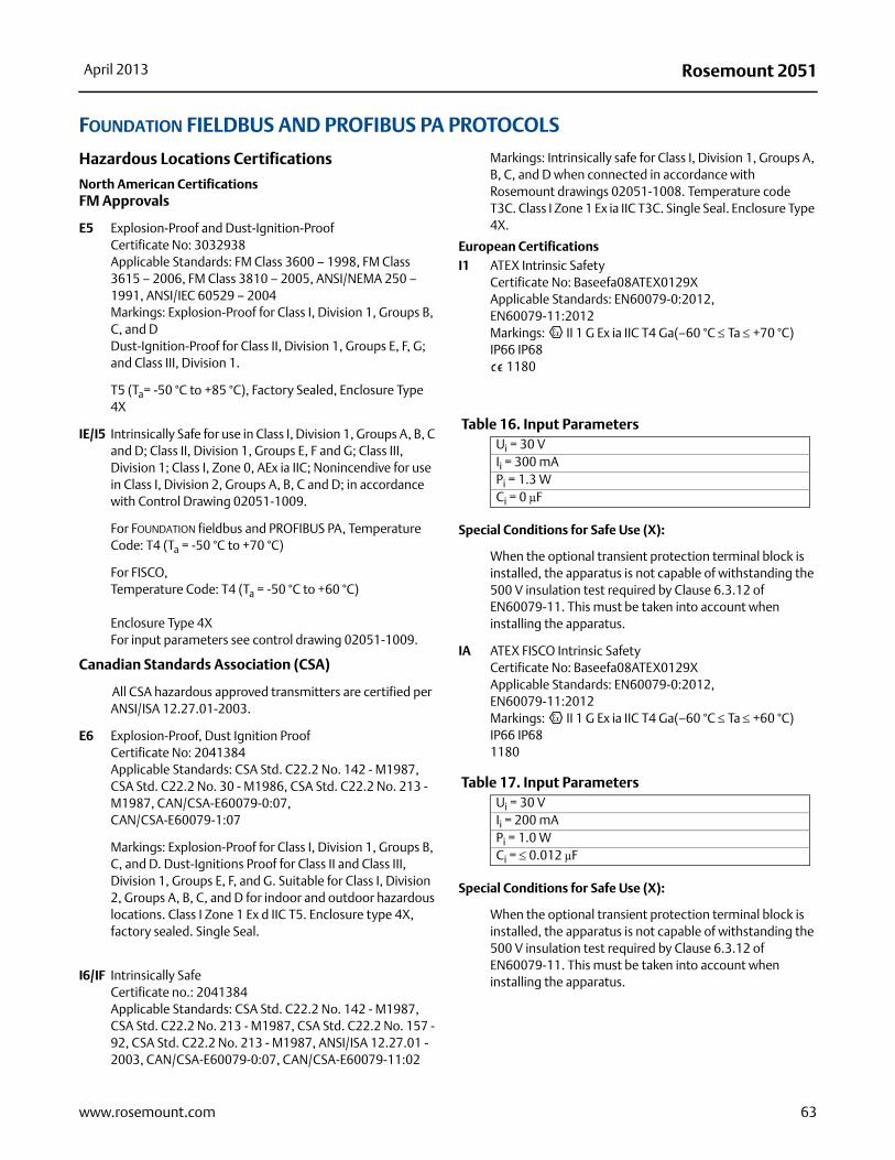
Rosemount 2051April 2013
63www.rosemount.com
FOUNDATION FIELDBUS AND PROFIBUS PA PROTOCOLS
Hazardous Locations Certifications
North American CertificationsFM Approvals
E5 Explosion-Proof and Dust-Ignition-ProofCertificate No: 3032938Applicable Standards: FM Class 3600 – 1998, FM Class 3615 – 2006, FM Class 3810 – 2005, ANSI/NEMA 250 – 1991, ANSI/IEC 60529 – 2004Markings: Explosion-Proof for Class I, Division 1, Groups B, C, and DDust-Ignition-Proof for Class II, Division 1, Groups E, F, G; and Class III, Division 1.
T5 (Ta= -50 °C to +85 °C), Factory Sealed, Enclosure Type 4X
IE/I5 Intrinsically Safe for use in Class I, Division 1, Groups A, B, C and D; Class II, Division 1, Groups E, F and G; Class III, Division 1; Class I, Zone 0, AEx ia IIC; Nonincendive for use in Class I, Division 2, Groups A, B, C and D; in accordance with Control Drawing 02051-1009.
For FOUNDATION fieldbus and PROFIBUS PA, Temperature Code: T4 (Ta = -50 °C to +70 °C)
For FISCO,Temperature Code: T4 (Ta = -50 °C to +60 °C)
Enclosure Type 4XFor input parameters see control drawing 02051-1009.
Canadian Standards Association (CSA)
All CSA hazardous approved transmitters are certified per ANSI/ISA 12.27.01-2003.
E6 Explosion-Proof, Dust Ignition ProofCertificate No: 2041384Applicable Standards: CSA Std. C22.2 No. 142 - M1987, CSA Std. C22.2 No. 30 - M1986, CSA Std. C22.2 No. 213 - M1987, CAN/CSA-E60079-0:07,CAN/CSA-E60079-1:07
Markings: Explosion-Proof for Class I, Division 1, Groups B, C, and D. Dust-Ignitions Proof for Class II and Class III, Division 1, Groups E, F, and G. Suitable for Class I, Division 2, Groups A, B, C, and D for indoor and outdoor hazardous locations. Class I Zone 1 Ex d IIC T5. Enclosure type 4X, factory sealed. Single Seal.
I6/IF Intrinsically SafeCertificate no.: 2041384Applicable Standards: CSA Std. C22.2 No. 142 - M1987, CSA Std. C22.2 No. 213 - M1987, CSA Std. C22.2 No. 157 - 92, CSA Std. C22.2 No. 213 - M1987, ANSI/ISA 12.27.01 - 2003, CAN/CSA-E60079-0:07, CAN/CSA-E60079-11:02
Markings: Intrinsically safe for Class I, Division 1, Groups A, B, C, and D when connected in accordance with Rosemount drawings 02051-1008. Temperature code T3C. Class I Zone 1 Ex ia IIC T3C. Single Seal. Enclosure Type 4X.
European CertificationsI1 ATEX Intrinsic Safety
Certificate No: Baseefa08ATEX0129XApplicable Standards: EN60079-0:2012, EN60079-11:2012Markings: II 1 G Ex ia IIC T4 Ga(–60 °C Ta +70 °C) IP66 IP68
1180
Special Conditions for Safe Use (X):
When the optional transient protection terminal block is installed, the apparatus is not capable of withstanding the 500 V insulation test required by Clause 6.3.12 of EN60079-11. This must be taken into account when installing the apparatus.
IA ATEX FISCO Intrinsic SafetyCertificate No: Baseefa08ATEX0129XApplicable Standards: EN60079-0:2012, EN60079-11:2012Markings: II 1 G Ex ia IIC T4 Ga(–60 °C Ta +60 °C)IP66 IP681180
Special Conditions for Safe Use (X):
When the optional transient protection terminal block is installed, the apparatus is not capable of withstanding the 500 V insulation test required by Clause 6.3.12 of EN60079-11. This must be taken into account when installing the apparatus.
Table 16. Input ParametersUi = 30 VIi = 300 mAPi = 1.3 W Ci = 0 μF
Table 17. Input ParametersUi = 30 VIi = 200 mAPi = 1.0 W Ci = 0.012 μF
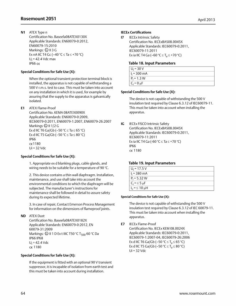
Rosemount 2051 April 2013
N1 ATEX Type nCertification No. Baseefa08ATEX0130X Applicable Standards: EN60079-0:2012, EN60079-15:2010Markings: II 3 GEx nA IIC T4 Gc (–40 °C Ta +70 °C)Ui = 42.4 Vdc maxIP66
Special Conditions for Safe Use (X):
When the optional transient protection terminal block is installed, the apparatus is not capable of withstanding a 500 V r.m.s. test to case. This must be taken into account on any installation in which it is used, for example by assuring that the supply to the apparatus is galvanically isolated.
E1 ATEX Flame-ProofCertification No. KEMA 08ATEX0090XApplicable Standards: EN60079-0:2009, IEC60079-0:2011, EN60079-1:2007, EN60079-26:2007Markings II 1/2 G Ex d IIC T6 Ga/Gb (–50 °C Ta 65 °C)Ex d IIC T5 Ga/Gb (–50 °C Ta 80 °C)IP66
1180Ui = 32 Vdc
Special Conditions for Safe Use (X):
1. Appropriate ex d blanking plugs, cable glands, and wiring needs to be suitable for a temperature of 90 °C.
2. This device contains a thin wall diaphragm. Installation, maintenance, and use shall take into account the environmental conditions to which the diaphragm will be subjected. The manufacturer’s instructions for maintenance shall be followed in detail to assure safety during its expected lifetime.
3. In case of repair, Contact Emerson Process Management for information on the dimensions of flameproof joints.
ND ATEX DustCertification No. Baseefa08ATEX0182XApplicable Standards: EN60079-0:2012, EN 60079-31:2009Markings: II 1 D Ex t IIIC T50 °C T500 60 °C DaIP66 IP68Ui = 42.4 Vdc
1180
Special Conditions for Safe Use (X):
If the equipment is fitted with an optional 90 V transient suppressor, it is incapable of isolation from earth test and this must be taken into account during installation.
IECEx CertificationsI7 IECEx Intrinsic Safety
Certification No. IECExBAS08.0045XApplicable Standards: IEC60079-0:2011, IEC60079-11:2011Ex ia IIC T4 Ga (–60 °C Ta +70 °C)
Special Conditions for Safe Use (X):
The device is not capable of withstanding the 500 V insulation test required by Clause 6.3.12 of IEC60079-11. This must be taken into account when installing the apparatus.
IG IECEx FISCO Intrinsic Safety Certification No. IECExBAS08.0045XApplicable Standards: IEC60079-0:2011, IEC60079-11:2011Ex ia IIC T4 Ga (-60 °C Ta +70 °C)IP66
1180
Special Conditions for Safe Use (X):
The device is not capable of withstanding the 500 V insulation test required by Clause 6.3.12 of IEC 60079-11. This must be taken into account when installing the apparatus.
E7 IECEx Flame-ProofCertification No. IECEx KEM 08.0024XApplicable Standards: IEC60079-0:2011, IEC60079-1:2007-04, IEC60079-26:2006Ex d IIC T6 Ga/Gb (–50 °C Ta 65 °C)Ex d IIC T5 Ga/Gb (–50 °C Ta 80 °C)Ui = 32 Vdc
Table 18. Input ParametersUi = 30 VIi = 300 mAPi = 1.3 W Ci = 0 μF
Table 19. Input ParametersUi = 17.5 VIi = 380 mAPi = 5.32 W Ci = 5 μFLi = 10 μH
64 www.rosemount.com
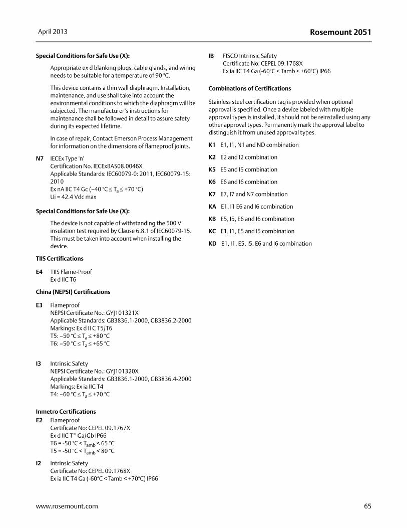
Rosemount 2051April 2013
Special Conditions for Safe Use (X):
Appropriate ex d blanking plugs, cable glands, and wiring needs to be suitable for a temperature of 90 °C.
This device contains a thin wall diaphragm. Installation, maintenance, and use shall take into account the environmental conditions to which the diaphragm will be subjected. The manufacturer’s instructions for maintenance shall be followed in detail to assure safety during its expected lifetime.
In case of repair, Contact Emerson Process Management for information on the dimensions of flameproof joints.
N7 IECEx Type 'n'Certification No. IECExBAS08.0046XApplicable Standards: IEC60079-0: 2011, IEC60079-15: 2010Ex nA IIC T4 Gc (–40 °C Ta +70 °C)Ui = 42.4 Vdc max
Special Conditions for Safe Use (X):
The device is not capable of withstanding the 500 V insulation test required by Clause 6.8.1 of IEC60079-15. This must be taken into account when installing the device.
TIIS Certifications
E4 TIIS Flame-ProofEx d IIC T6
China (NEPSI) Certifications
E3 FlameproofNEPSI Certificate No.: GYJ101321XApplicable Standards: GB3836.1-2000, GB3836.2-2000Markings: Ex d II C T5/T6T5: –50 °C Ta +80 °CT6: –50 °C Ta +65 °C
I3 Intrinsic SafetyNEPSI Certificate No.: GYJ101320XApplicable Standards: GB3836.1-2000, GB3836.4-2000Markings: Ex ia IIC T4T4: –60 °C Ta +70 °C
Inmetro Certifications E2 Flameproof
Certificate No: CEPEL 09.1767XEx d IIC T* Ga/Gb IP66T6 = -50 °C < Tamb < 65 °CT5 = -50 °C < Tamb < 80 °C
I2 Intrinsic SafetyCertificate No: CEPEL 09.1768XEx ia IIC T4 Ga (-60°C < Tamb < +70°C) IP66
IB FISCO Intrinsic SafetyCertificate No: CEPEL 09.1768XEx ia IIC T4 Ga (-60°C < Tamb < +60°C) IP66
Combinations of Certifications
Stainless steel certification tag is provided when optional approval is specified. Once a device labeled with multiple approval types is installed, it should not be reinstalled using any other approval types. Permanently mark the approval label to distinguish it from unused approval types.
K1 E1, I1, N1 and ND combination
K2 E2 and I2 combination
K5 E5 and I5 combination
K6 E6 and I6 combination
K7 E7, I7 and N7 combination
KA E1, I1 E6 and I6 combination
KB E5, I5, E6 and I6 combination
KC E1, I1, E5 and I5 combination
KD E1, I1, E5, I5, E6 and I6 combination
65www.rosemount.com

Rosemount 2051 April 2013
IEC 62591 (WirelessHART Protocol)
Approved manufacturing locationsRosemount Inc. — Chanhassen, Minnesota USAFisher-Rosemount GmbH & Co. — Wessling, GermanyEmerson Process Management Asia Pacific Private Limited — SingaporeBeijing Rosemount Far East Instrument Co., LTD — Beijing, China
European directive informationThe most recent revision of the EC declaration of conformity can be found at www.rosemount.com.
Telecommunication complianceAll wireless devices require certification to ensure that they adhere to regulations regarding the use of the RF spectrum. Nearly every country requires this type of product certification. Emerson is working with governmental agencies around the world to supply fully compliant products and remove the risk of violating country directives or laws governing wireless device usage.
FCC and ICThis device complies with Part 15 of the FCC Rules. Operation is subject to the following conditions: This device may not cause harmful interference. This device must accept any interference received, including interference that may cause undesired operation. This device must be installed to ensure a minimum antenna separation distance of 20 cm from all persons.
Ordinary location certification for FMAs standard, the transmitter has been examined and tested to determine that the design meets basic electrical, mechanical, and fire protection requirements by FM, a nationally recognized testing laboratory (NRTL) as accredited by the Federal Occupational Safety and Health Administration (OSHA).
North American certifications
Factory Mutual (FM) approvals
I5 FM Intrinsically SafeCertificate No: 3045342Applicable Standards: Class 3600:2011, Class 3610:2010, Class 3810: 2005Markings: Intrinsically Safe for Class I, Division I, Groups A, B, C, D Zone Marking: Class I Zone 0, AEx ia IICT4 (-40 °C to 70 °C)Intrinsically Safe when installed according to Rosemount Drawing 03031-1062Enclosure Type 4X/IP66/IP68
Specific Conditions for Safe Use:
The inline pressure sensor may contain more than 10% aluminum and is considered a potential risk of ignition by impact or friction. Care must be taken into account during installation and use to prevent impact and friction.
The surface resistivity of the transmitter is greater than one gigaohm. To avoid electrostatic charge build-up, it must not be rubbed or cleaned with solvents or a dry cloth.
The Model 2051 Wireless pressure Transmitter shall only be used with the 701PGNKF Rosemount Smartpower Battery Pack.
CSA - Canadian Standards Association
I6 CSA Intrinsically SafeCertificate No: 2526009Applicable Standards: CSA C22.2 No. 0-M91, CSA C22.2 No. 159-92Markings: Intrinsically Safe For Class I, Division I, Groups A, B, C, DT4 (-40 °C to 70 °C)Intrinsically safe when installed according to Rosemount drawing 03031-1063Enclosure Type 4X/IP66/IP68
European certifications
I1 ATEX Intrinsic SafetyCertificate No: Baseefa12ATEX0228XApplicable Standards: EN60079-11:2012, EN60079-0:2012Markings: Ex ia IIC T4 Ga (-40 °C Ta 70 °C)
II 1GIP66/68
1180
66 www.rosemount.com
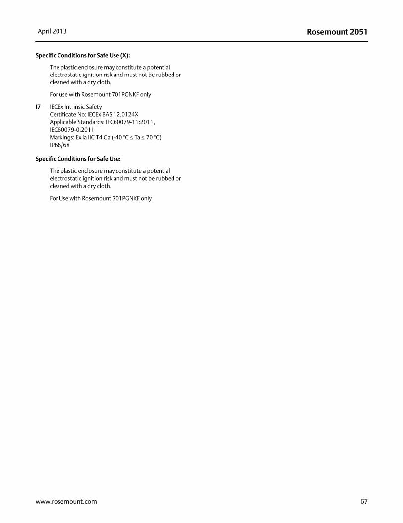
Rosemount 2051April 2013
Specific Conditions for Safe Use (X):
The plastic enclosure may constitute a potential electrostatic ignition risk and must not be rubbed or cleaned with a dry cloth.
For use with Rosemount 701PGNKF only
I7 IECEx Intrinsic SafetyCertificate No: IECEx BAS 12.0124XApplicable Standards: IEC60079-11:2011, IEC60079-0:2011Markings: Ex ia IIC T4 Ga (-40 °C Ta 70 °C)IP66/68
Specific Conditions for Safe Use:
The plastic enclosure may constitute a potential electrostatic ignition risk and must not be rubbed or cleaned with a dry cloth.
For Use with Rosemount 701PGNKF only
67www.rosemount.com

Rosemount 2051 April 2013
Dimensional drawings2051C Exploded View
Electronics Housing
Terminal Block
Cover O-ring
CoverElectronics Board
Sensor Module
Housing Rotation Set Screw(180° Maximum Housing Rotation without Further Disassembly)
Flange Alignment Screw (Not Pressure Retaining)
Flange Bolts
Flange Adapters
Drain/Vent Valve
Coplanar Flange
Flange Adapter O-Ring
Process O-Ring
Local Configuration Buttons(1)
Nameplate
1) Span and Zero Adjustment Buttons are optional with 4-20 mA and 1-5 Vdc HART protocol. Local Operator Interface buttons are
optional for PROFIBUS PA protocol. Local Configuration Buttons are not available with FOUNDATION fieldbus.
68 www.rosemount.com
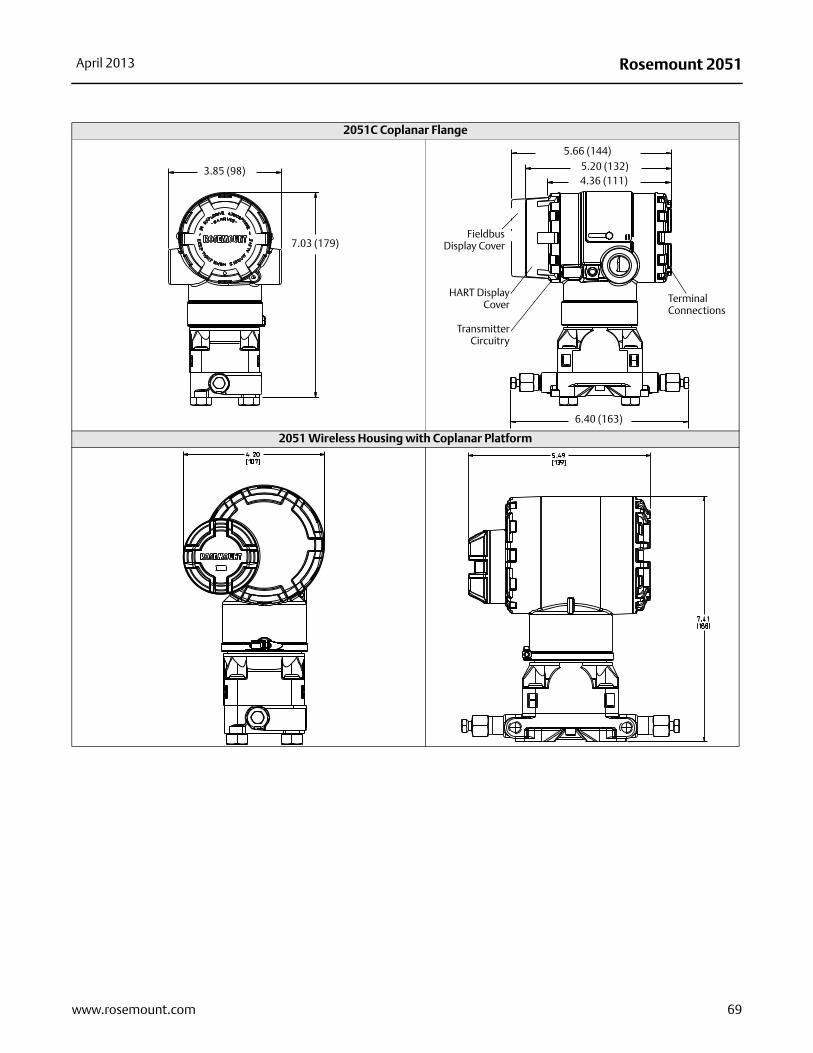
Rosemount 2051April 2013
2051C Coplanar Flange
2051 Wireless Housing with Coplanar Platform
3.85 (98)
7.03 (179)
6.40 (163)
4.36 (111)5.20 (132)
5.66 (144)
Terminal Connections
FieldbusDisplay Cover
HART DisplayCover
TransmitterCircuitry
69www.rosemount.com
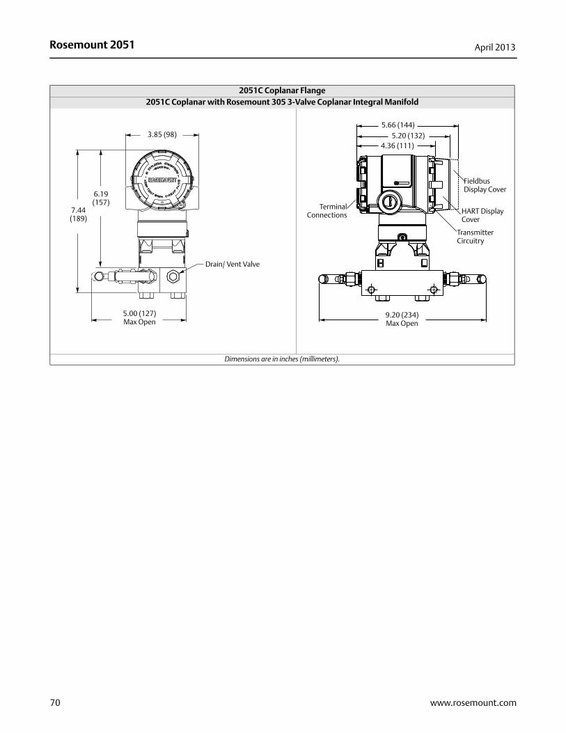
Rosemount 2051 April 2013
2051C Coplanar with Rosemount 305 3-Valve Coplanar Integral Manifold
Dimensions are in inches (millimeters).
2051C Coplanar Flange
3.85 (98)
7.44 (189)
Drain/ Vent Valve
5.00 (127)Max Open
6.19 (157)
9.20 (234)Max Open
4.36 (111)5.20 (132)
5.66 (144)
TerminalConnections
Fieldbus Display Cover
HART Display Cover
Transmitter Circuitry
70 www.rosemount.com
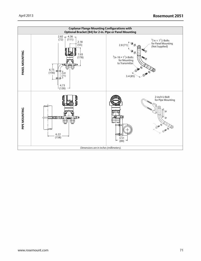
Rosemount 2051April 2013
Coplanar Flange Mounting Configurations with Optional Bracket (B4) for 2-in. Pipe or Panel Mounting
PAN
EL M
OU
NTI
NG
PIPE
MO
UN
TIN
G
Dimensions are in inches (millimeters).
4.36(111)
2.82(72)
7.03 (178)
2.81(71)
4.73(120)
6.15(156)
2.18(55)
5/16 � 11/2 Bolts for Panel Mounting(Not Supplied)
3/8–16 × 11/4 Boltsfor Mounting
to Transmitter
2.8 (71)
3.4 (85)
6.22(158) 3.51
(89)
2-inch U-Boltfor Pipe Mounting
71www.rosemount.com
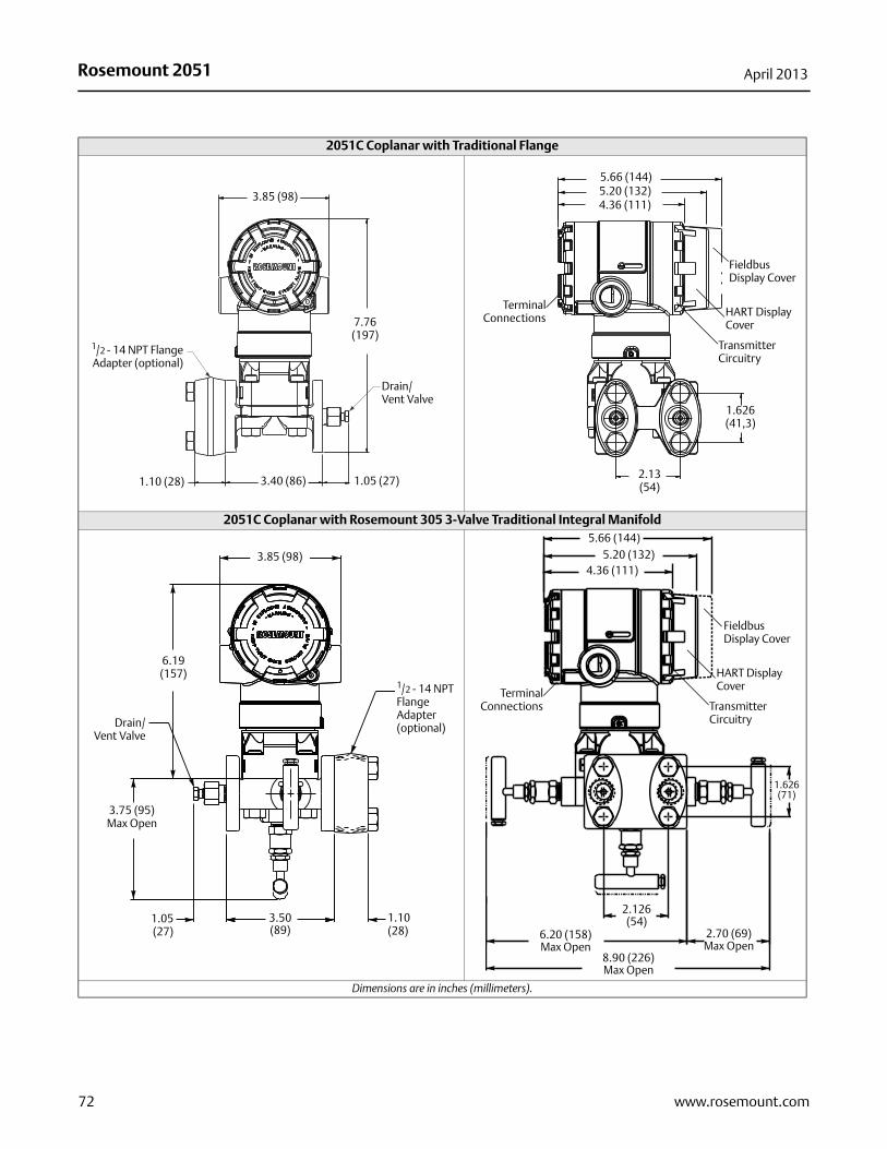
Rosemount 2051 April 2013
2051C Coplanar with Traditional Flange
2051C Coplanar with Rosemount 305 3-Valve Traditional Integral Manifold
Dimensions are in inches (millimeters).
3.85 (98)
7.76(197)
3.40 (86)1.10 (28)
1/2 - 14 NPT FlangeAdapter (optional)
Drain/Vent Valve
1.05 (27)
1.626(41,3)
2.13(54)
4.36 (111)5.20 (132)5.66 (144)
TerminalConnections
Fieldbus Display Cover
HART Display Cover
Transmitter Circuitry
3.85 (98)
1/2 - 14 NPT Flange Adapter (optional)Drain/
Vent Valve
3.50(89)
1.05(27)
1.10(28)
3.75 (95)Max Open
6.19(157)
2.126(54)
6.20 (158)Max Open
8.90 (226)Max Open
2.70 (69)Max Open
1.626(71)
4.36 (111)5.20 (132)
5.66 (144)
TerminalConnections
Fieldbus Display Cover
HART Display Cover
Transmitter Circuitry
72 www.rosemount.com
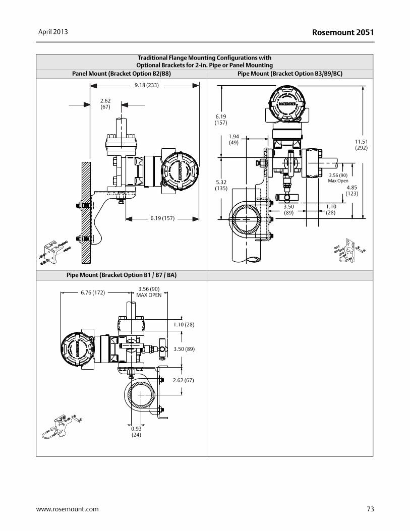
Rosemount 2051April 2013
Traditional Flange Mounting Configurations withOptional Brackets for 2-in. Pipe or Panel Mounting
Panel Mount (Bracket Option B2/B8) Pipe Mount (Bracket Option B3/B9/BC)
Pipe Mount (Bracket Option B1 / B7 / BA)
Dimensions are in inches (millimeters).
9.18 (233)
2.62 (67)
6.19 (157)
5.32(135)
1.94(49)
3.50(89)
1.10(28)
3.56 (90)Max Open
4.85(123)
6.19(157)
11.51(292)
6.76 (172)3.56 (90)
MAX OPEN
1.10 (28)
3.50 (89)
2.62 (67)
0.93 (24)
73www.rosemount.com
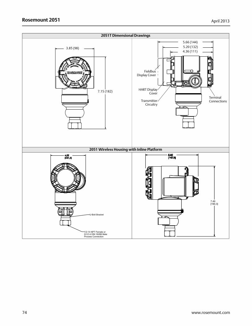
Rosemount 2051 April 2013
2051T Dimensional Drawings
2051 Wireless Housing with Inline Platform
3.85 (98)
7.15 (182)
4.36 (111)5.20 (132)5.66 (144)
Terminal Connections
FieldbusDisplay Cover
HART DisplayCover
TransmitterCircuitry
74 www.rosemount.com
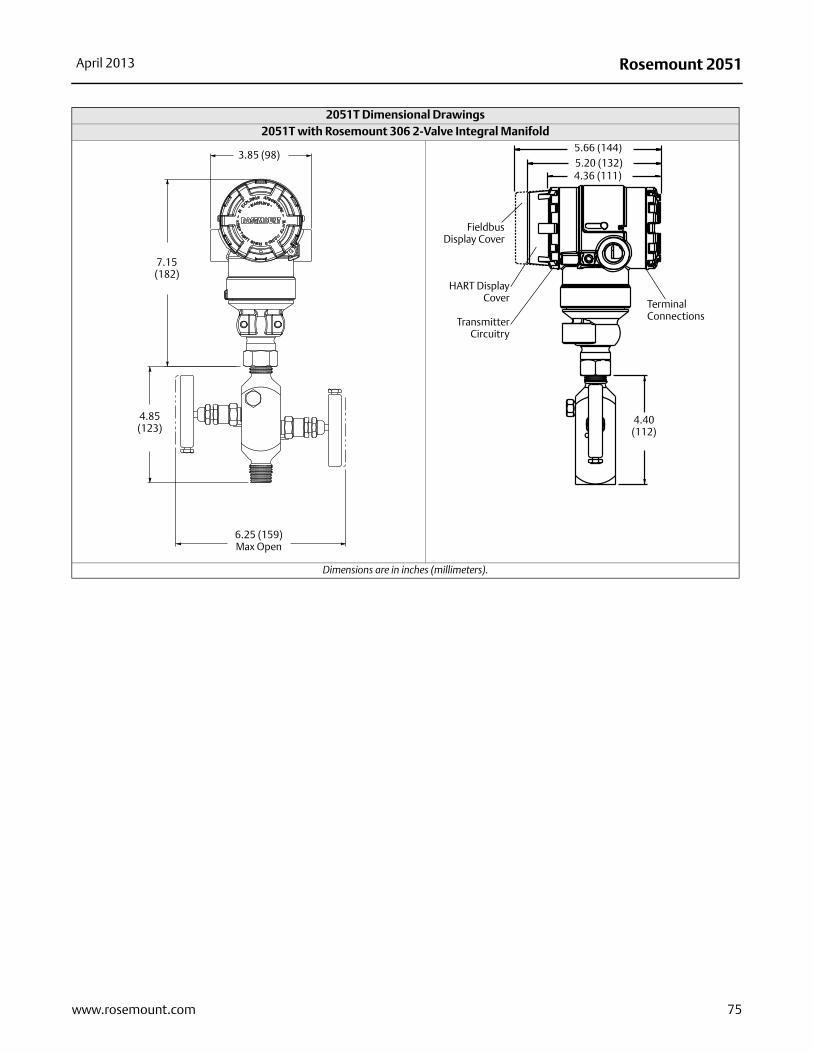
Rosemount 2051April 2013
2051T with Rosemount 306 2-Valve Integral Manifold
Dimensions are in inches (millimeters).
2051T Dimensional Drawings
3.85 (98)
7.15 (182)
4.85 (123)
6.25 (159)Max Open
4.40 (112)
4.36 (111)5.20 (132)5.66 (144)
Terminal Connections
FieldbusDisplay Cover
HART DisplayCover
TransmitterCircuitry
75www.rosemount.com
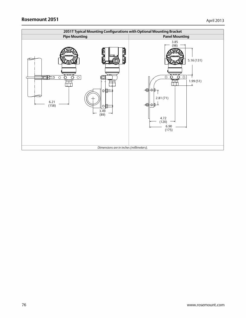
Rosemount 2051 April 2013
2051T Typical Mounting Configurations with Optional Mounting BracketPipe Mounting Panel Mounting
Dimensions are in inches (millimeters).
6.21 (158)
3.49(89)
3.85(98)
1.99 (51)
4.72(120)
6.90(175)
2.81 (71)
5.16 (131)
76 www.rosemount.com
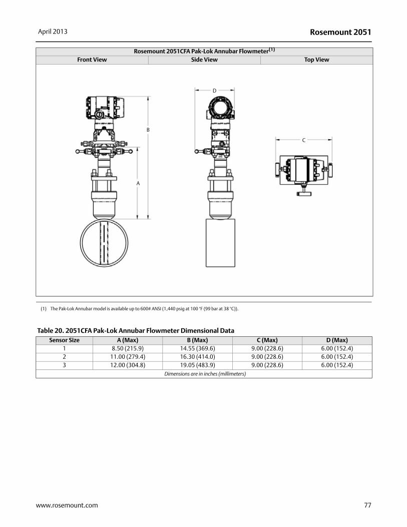
Rosemount 2051April 2013
Rosemount 2051CFA Pak-Lok Annubar Flowmeter(1)
Front View Side View Top View
(1) The Pak-Lok Annubar model is available up to 600# ANSI (1,440 psig at 100 °F (99 bar at 38 °C)).
B
A
D
C
Table 20. 2051CFA Pak-Lok Annubar Flowmeter Dimensional DataSensor Size A (Max) B (Max) C (Max) D (Max)
1 8.50 (215.9) 14.55 (369.6) 9.00 (228.6) 6.00 (152.4)2 11.00 (279.4) 16.30 (414.0) 9.00 (228.6) 6.00 (152.4)3 12.00 (304.8) 19.05 (483.9) 9.00 (228.6) 6.00 (152.4)
Dimensions are in inches (millimeters)
77www.rosemount.com
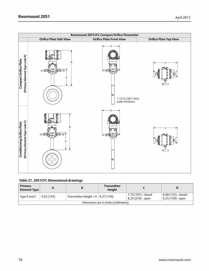
Rosemount 2051 April 2013
Rosemount 2051CFC Compact Orifice Flowmeter Orifice Plate Side View Orifice Plate Front View Orifice Plate Top View
Com
pac
t O
rifi
ce P
late
(P
rim
ary
Elem
ent
Typ
e co
de
P)
Con
dit
ion
ing
Ori
fice
Pla
te
(Pri
mar
y El
emen
t Ty
pe
cod
e C
)
1.13-in. (28.7 mm) wafer thickness
Table 21. 2051CFC Dimensional drawings
Primary Element Type
A BTransmitter
HeightC D
Type P and C 5.62 (143) Transmitter Height + A 6.27 (159)7.75 (197) - closed8.25 (210) - open
6.00 (152) - closed6.25 (159) - open
Dimensions are in inches (millimeters).
78 www.rosemount.com
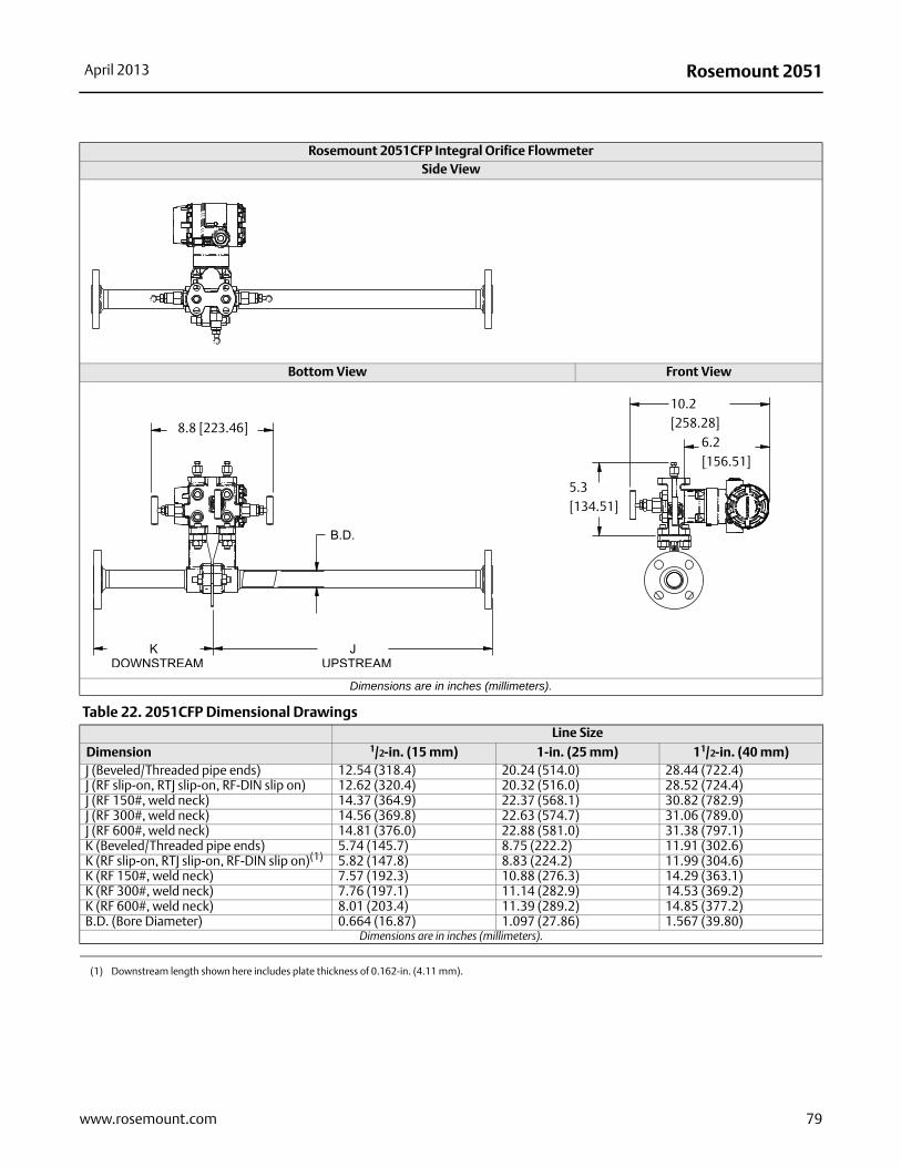
Rosemount 2051April 2013
Rosemount 2051CFP Integral Orifice Flowmeter Side View
Bottom View Front View
Dimensions are in inches (millimeters).
Table 22. 2051CFP Dimensional DrawingsLine Size
Dimension 1/2-in. (15 mm) 1-in. (25 mm) 11/2-in. (40 mm)J (Beveled/Threaded pipe ends) 12.54 (318.4) 20.24 (514.0) 28.44 (722.4)J (RF slip-on, RTJ slip-on, RF-DIN slip on) 12.62 (320.4) 20.32 (516.0) 28.52 (724.4)J (RF 150#, weld neck) 14.37 (364.9) 22.37 (568.1) 30.82 (782.9)J (RF 300#, weld neck) 14.56 (369.8) 22.63 (574.7) 31.06 (789.0)J (RF 600#, weld neck) 14.81 (376.0) 22.88 (581.0) 31.38 (797.1)K (Beveled/Threaded pipe ends) 5.74 (145.7) 8.75 (222.2) 11.91 (302.6)K (RF slip-on, RTJ slip-on, RF-DIN slip on)(1) 5.82 (147.8) 8.83 (224.2) 11.99 (304.6)K (RF 150#, weld neck) 7.57 (192.3) 10.88 (276.3) 14.29 (363.1)K (RF 300#, weld neck) 7.76 (197.1) 11.14 (282.9) 14.53 (369.2)K (RF 600#, weld neck) 8.01 (203.4) 11.39 (289.2) 14.85 (377.2)B.D. (Bore Diameter) 0.664 (16.87) 1.097 (27.86) 1.567 (39.80)
Dimensions are in inches (millimeters).
(1) Downstream length shown here includes plate thickness of 0.162-in. (4.11 mm).
8.8 [223.46]
10.2 [258.28]
6.2 [156.51]
5.3 [134.51]
79www.rosemount.com
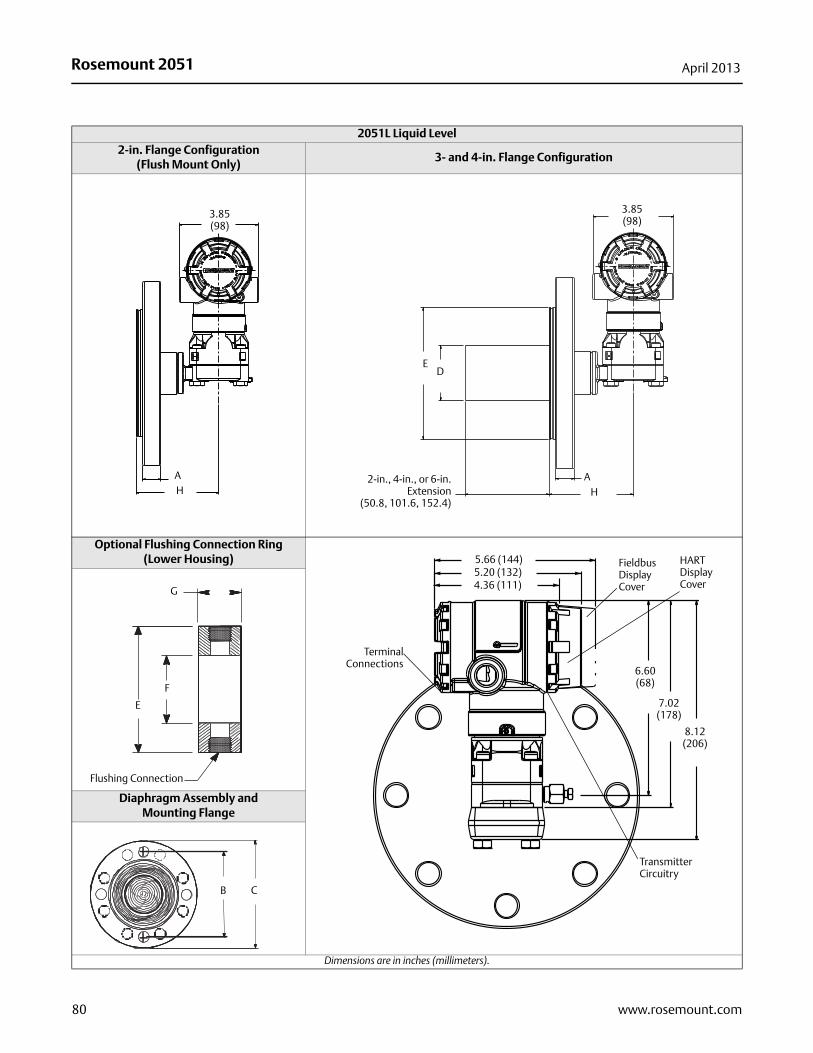
Rosemount 2051 April 2013
2051L Liquid Level 2-in. Flange Configuration
(Flush Mount Only)3- and 4-in. Flange Configuration
Optional Flushing Connection Ring (Lower Housing)
Diaphragm Assembly and Mounting Flange
Dimensions are in inches (millimeters).
3.85(98)
AH
3.85(98)
D
AH
2-in., 4-in., or 6-in.Extension
(50.8, 101.6, 152.4)
E
6.60(68)
7.02(178)
8.12(206)
4.36 (111)5.20 (132)5.66 (144)
TerminalConnections
Fieldbus Display Cover
HART Display Cover
Transmitter Circuitry
Flushing Connection
E
F
G
CB
80 www.rosemount.com
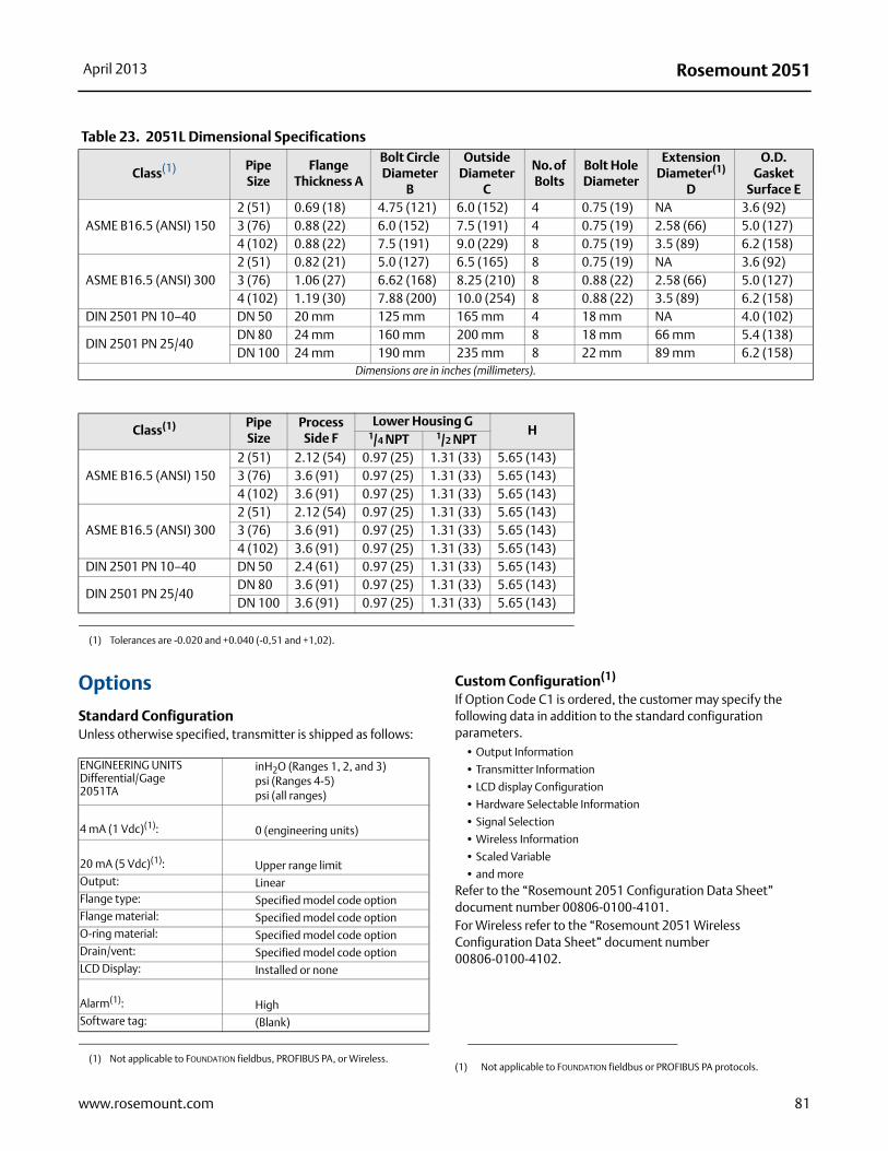
Rosemount 2051April 2013
Options
Standard ConfigurationUnless otherwise specified, transmitter is shipped as follows:
Custom Configuration(1)
If Option Code C1 is ordered, the customer may specify the following data in addition to the standard configuration parameters.
• Output Information
• Transmitter Information
• LCD display Configuration
• Hardware Selectable Information
• Signal Selection
• Wireless Information
• Scaled Variable
• and moreRefer to the “Rosemount 2051 Configuration Data Sheet” document number 00806-0100-4101.For Wireless refer to the “Rosemount 2051 Wireless Configuration Data Sheet” document number 00806-0100-4102.
Table 23. 2051L Dimensional Specifications
Class(1) Pipe Size
Flange Thickness A
Bolt Circle Diameter
B
Outside Diameter
C
No. of Bolts
Bolt Hole Diameter
Extension Diameter(1)
D
O.D. Gasket
Surface E
ASME B16.5 (ANSI) 1502 (51) 0.69 (18) 4.75 (121) 6.0 (152) 4 0.75 (19) NA 3.6 (92)3 (76) 0.88 (22) 6.0 (152) 7.5 (191) 4 0.75 (19) 2.58 (66) 5.0 (127)4 (102) 0.88 (22) 7.5 (191) 9.0 (229) 8 0.75 (19) 3.5 (89) 6.2 (158)
ASME B16.5 (ANSI) 3002 (51) 0.82 (21) 5.0 (127) 6.5 (165) 8 0.75 (19) NA 3.6 (92)3 (76) 1.06 (27) 6.62 (168) 8.25 (210) 8 0.88 (22) 2.58 (66) 5.0 (127)4 (102) 1.19 (30) 7.88 (200) 10.0 (254) 8 0.88 (22) 3.5 (89) 6.2 (158)
DIN 2501 PN 10–40 DN 50 20 mm 125 mm 165 mm 4 18 mm NA 4.0 (102)
DIN 2501 PN 25/40DN 80 24 mm 160 mm 200 mm 8 18 mm 66 mm 5.4 (138)DN 100 24 mm 190 mm 235 mm 8 22 mm 89 mm 6.2 (158)
Dimensions are in inches (millimeters).
Class(1) Pipe Size
Process Side F
Lower Housing GH1/4 NPT 1/2 NPT
ASME B16.5 (ANSI) 1502 (51) 2.12 (54) 0.97 (25) 1.31 (33) 5.65 (143)3 (76) 3.6 (91) 0.97 (25) 1.31 (33) 5.65 (143)4 (102) 3.6 (91) 0.97 (25) 1.31 (33) 5.65 (143)
ASME B16.5 (ANSI) 3002 (51) 2.12 (54) 0.97 (25) 1.31 (33) 5.65 (143)3 (76) 3.6 (91) 0.97 (25) 1.31 (33) 5.65 (143)4 (102) 3.6 (91) 0.97 (25) 1.31 (33) 5.65 (143)
DIN 2501 PN 10–40 DN 50 2.4 (61) 0.97 (25) 1.31 (33) 5.65 (143)
DIN 2501 PN 25/40DN 80 3.6 (91) 0.97 (25) 1.31 (33) 5.65 (143)DN 100 3.6 (91) 0.97 (25) 1.31 (33) 5.65 (143)
(1) Tolerances are -0.020 and +0.040 (-0,51 and +1,02).
ENGINEERING UNITSDifferential/Gage2051TA
inH2O (Ranges 1, 2, and 3)psi (Ranges 4-5)psi (all ranges)
4 mA (1 Vdc)(1):
(1) Not applicable to FOUNDATION fieldbus, PROFIBUS PA, or Wireless.
0 (engineering units)
20 mA (5 Vdc)(1): Upper range limitOutput: LinearFlange type: Specified model code optionFlange material: Specified model code optionO-ring material: Specified model code optionDrain/vent: Specified model code optionLCD Display: Installed or none
Alarm(1): HighSoftware tag: (Blank)
(1) Not applicable to FOUNDATION fieldbus or PROFIBUS PA protocols.
81www.rosemount.com
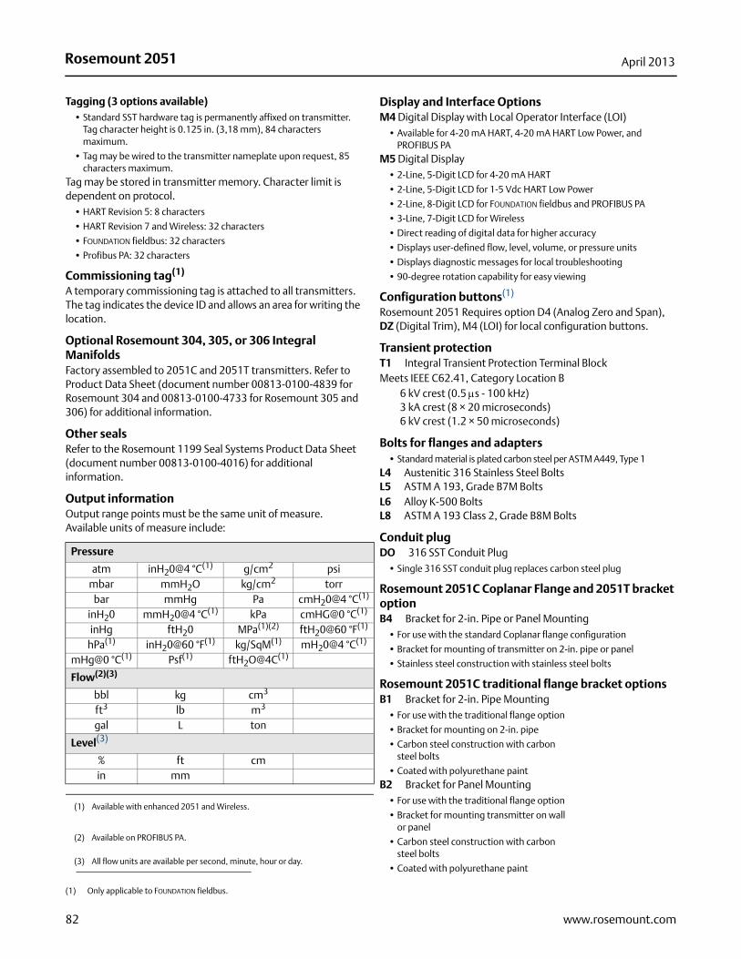
Rosemount 2051 April 2013
Tagging (3 options available)• Standard SST hardware tag is permanently affixed on transmitter.
Tag character height is 0.125 in. (3,18 mm), 84 characters maximum.
• Tag may be wired to the transmitter nameplate upon request, 85 characters maximum.
Tag may be stored in transmitter memory. Character limit is dependent on protocol.
• HART Revision 5: 8 characters
• HART Revision 7 and Wireless: 32 characters
• FOUNDATION fieldbus: 32 characters
• Profibus PA: 32 characters
Commissioning tag(1)
A temporary commissioning tag is attached to all transmitters. The tag indicates the device ID and allows an area for writing the location.
Optional Rosemount 304, 305, or 306 Integral ManifoldsFactory assembled to 2051C and 2051T transmitters. Refer to Product Data Sheet (document number 00813-0100-4839 for Rosemount 304 and 00813-0100-4733 for Rosemount 305 and 306) for additional information.
Other sealsRefer to the Rosemount 1199 Seal Systems Product Data Sheet (document number 00813-0100-4016) for additional information.
Output informationOutput range points must be the same unit of measure. Available units of measure include:
Display and Interface OptionsM4 Digital Display with Local Operator Interface (LOI)
• Available for 4-20 mA HART, 4-20 mA HART Low Power, and PROFIBUS PA
M5 Digital Display• 2-Line, 5-Digit LCD for 4-20 mA HART
• 2-Line, 5-Digit LCD for 1-5 Vdc HART Low Power
• 2-Line, 8-Digit LCD for FOUNDATION fieldbus and PROFIBUS PA
• 3-Line, 7-Digit LCD for Wireless
• Direct reading of digital data for higher accuracy
• Displays user-defined flow, level, volume, or pressure units
• Displays diagnostic messages for local troubleshooting
• 90-degree rotation capability for easy viewing
Configuration buttons(1)
Rosemount 2051 Requires option D4 (Analog Zero and Span), DZ (Digital Trim), M4 (LOI) for local configuration buttons.
Transient protectionT1 Integral Transient Protection Terminal BlockMeets IEEE C62.41, Category Location B
6 kV crest (0.5 s - 100 kHz)3 kA crest (8 × 20 microseconds)6 kV crest (1.2 × 50 microseconds)
Bolts for flanges and adapters• Standard material is plated carbon steel per ASTM A449, Type 1
L4 Austenitic 316 Stainless Steel BoltsL5 ASTM A 193, Grade B7M BoltsL6 Alloy K-500 BoltsL8 ASTM A 193 Class 2, Grade B8M Bolts
Conduit plugDO 316 SST Conduit Plug
• Single 316 SST conduit plug replaces carbon steel plug
Rosemount 2051C Coplanar Flange and 2051T bracket optionB4 Bracket for 2-in. Pipe or Panel Mounting
• For use with the standard Coplanar flange configuration
• Bracket for mounting of transmitter on 2-in. pipe or panel
• Stainless steel construction with stainless steel bolts
Rosemount 2051C traditional flange bracket optionsB1 Bracket for 2-in. Pipe Mounting
• For use with the traditional flange option
• Bracket for mounting on 2-in. pipe
• Carbon steel construction with carbonsteel bolts
• Coated with polyurethane paintB2 Bracket for Panel Mounting
• For use with the traditional flange option
• Bracket for mounting transmitter on wallor panel
• Carbon steel construction with carbonsteel bolts
• Coated with polyurethane paint
(1) Only applicable to FOUNDATION fieldbus.
Pressure
atm inH20@4 °C(1)
(1) Available with enhanced 2051 and Wireless.
g/cm2 psimbar mmH2O kg/cm2 torr
bar mmHg Pa cmH20@4 °C(1)
inH20 mmH20@4 °C(1) kPa cmHG@0 °C(1)
inHg ftH20 MPa(1)(2)
(2) Available on PROFIBUS PA.
ftH20@60 °F(1)
hPa(1) inH20@60 °F(1) kg/SqM(1) mH20@4 °C(1)
mHg@0 °C(1) Psf(1) ftH2O@4C(1)
Flow(2)(3)
(3) All flow units are available per second, minute, hour or day.
bbl kg cm3
ft3 lb m3
gal L ton
Level(3)
% ft cmin mm
82 www.rosemount.com
Rosemount 2051April 2013
83www.rosemount.com
B3 Flat Bracket for 2-in. Pipe Mounting• For use with the traditional flange option
• Bracket for vertical mounting of transmitter on 2-in. pipe
• Carbon steel construction with carbonsteel bolts
• Coated with polyurethane paintB7 B1 Bracket with SST Bolts
• Same bracket as the B1 option with Series 300 stainless steel boltsB8 B2 Bracket with SST Bolts
• Same bracket as the B2 option with Series 300 stainless steel boltsB9 B3 Bracket with SST Bolts
• Same bracket as the B3 option with Series 300 stainless steel boltsBA Stainless Steel B1 Bracket with SST Bolts
• B1 bracket in stainless steel with Series 300 stainless steel boltsBC Stainless Steel B3 Bracket with SST Bolts
• B3 bracket in stainless steel with Series 300 stainless steel bolts
Rosemount 205100813-0100-4101 Rev JA
Product Data SheetApril 2013
Emerson Process ManagementRosemount Inc.8200 Market BoulevardChanhassen, MN 55317 USAT (U.S.) 1-800-999-9307T (International) (952) 906-8888F (952) 906-8889www.rosemount.com
Emerson Process ManagementBlegistrasse 23P.O. Box 1046CH 6341 BaarSwitzerlandT +41 (0) 41 768 6111F +41 (0) 41 768 6300www.rosemount.com
Emerson Process Management Asia Pacific Pte Ltd1 Pandan CrescentSignapore 128461T +65 6777 8211F +65 6777 0947Service Support Hotline: +65 6770 8711Email: [email protected]
Emerson Process Management Latin America1300 Concord Terrace, Suite 400Sunrise Florida 33323 USATel + 1 954 846 5030
Standard Terms and Conditions of Sale can be found at www.rosemount.com\terms_of_saleThe Emerson logo is a trade mark and service mark of Emerson Electric Co.Rosemount and the Rosemount logotype are registered trademarks of Rosemount Inc.PlantWeb is a registered trademark of one of the Emerson Process Management group of companies.HART and WirelessHART are registered trademarks of the HART Communication FoundationModbus is a trademark of Modicon, Inc.All other marks are the property of their respective owners.© 2013 Rosemount Inc. All rights reserved.