rosemount 3144p temperature...
TRANSCRIPT
Product Data SheetJanuary 2014
00813-0100-4021, Rev MA
Industry-leading temperature transmitter delivers unmatched field reliability and innovative process measurement solutions
Improve efficiency with Best-in-Class product specifications and capabilities
Optimize measurement reliability with diagnostics designed for any protocol on any host system
Explore the benefits of a Complete Point Solution from Rosemount Temperature
Rosemount 3144P Temperature Transmitter
2
Rosemount 3144P January 2014
www.rosemount.com
Rosemount 3144P Temperature Transmitter
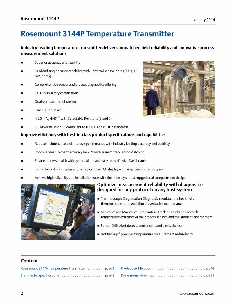
Industry-leading temperature transmitter delivers unmatched field reliability and innovative process measurement solutions
Superior accuracy and stability
Dual and single sensor capability with universal sensor inputs (RTD, T/C, mV, ohms)
Comprehensive sensor and process diagnostics offering
IEC 61508 safety certification
Dual-compartment housing
Large LCD display
4-20 mA /HART® with Selectable Revisions (5 and 7)
FOUNDATION Fieldbus, compliant to ITK 6.0 and NE107 standards
Improve efficiency with best-in-class product specifications and capabilities
Reduce maintenance and improve performance with industry leading accuracy and stability
Improve measurement accuracy by 75% with Transmitter-Sensor Matching
Ensure process health with system alerts and easy to use Device Dashboards
Easily check device status and values on local LCD display with large percent range graph
Achieve high reliability and installation ease with the industry's most rugged dual compartment design
Optimize measurement reliability with diagnostics designed for any protocol on any host system
Thermocouple Degradation Diagnostic monitors the health of a thermocouple loop, enabling preventative maintenance
Minimum and Maximum Temperature Tracking tracks and records temperature extremes of the process sensors and the ambient environment
Sensor Drift Alert detects sensor drift and alerts the user
Hot Backup® provides temperature measurement redundancy
Content
Rosemount 3144P Temperature Transmitter . . . . . . . . . page 2
Transmitter specifications . . . . . . . . . . . . . . . . . . . . . . . . page 8
Product certifications . . . . . . . . . . . . . . . . . . . . . . . . . . . page 16
Dimensional drawings . . . . . . . . . . . . . . . . . . . . . . . . . . page 21

3
Rosemount 3144PJanuary 2014
www.rosemount.com
Explore the benefits of a complete point solution from Rosemount Temperature
An “Assemble To Sensor” option enables Emerson to provide a complete point temperature solution, delivering an installation-ready transmitter and sensor assembly
Emerson offers a selection of RTDs, thermocouples, and thermowells that bring superior durability and Rosemount reliability to temperature sensing, complementing the Rosemount Transmitter portfolio
Experience global consistency and local support from numerous worldwide Rosemount Temperature manufacturing sites
World-class manufacturing provides globally consistent product from every factory and the capacity to fulfill the needs of any project, large or small
Experienced Instrumentation Consultants help select the right product for any temperature application and advise on best installation practices
An extensive global network of Emerson service and support personnel can be on-site when and where they are needed
Looking for a wireless temperature solution? For wireless applications that require superior performance and unmatched reliability, consider the Rosemount 648 Wireless temperature transmitter.
A demanding high temperature application requires an innovative temperature solution. Pair the Rosemount 3144P Thermocouple Diagnostic with the Rosemount 1075 High Temperature Thermocouple.
4
Rosemount 3144P January 2014
www.rosemount.com
Rosemount 3144P Temperature Transmitter
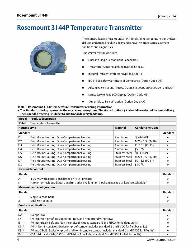
The industry-leading Rosemount 3144P Single Point temperature transmitter delivers unmatched field reliability and innovative process measurement solutions and diagnostics
Transmitter features include:
Dual and Single Sensor Input Capabilities
Transmitter-Sensor Matching (Option Code C2)
Integral Transient Protector (Option Code T1)
IEC 61508 Safety Certificate of Compliance (Option Code QT)
Advanced Sensor and Process Diagnostics (Option Codes D01 and DA1)
Large, Easy to Read LCD Display (Option Code M5)
“Assemble to Sensor” option (Option Code XA)
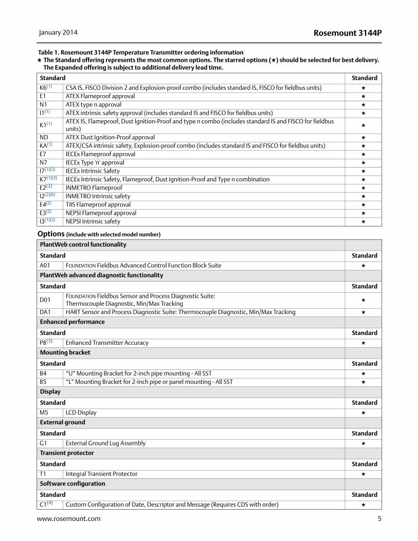
Table 1. Rosemount 3144P Temperature Transmitter ordering information★ The Standard offering represents the most common options. The starred options (★) should be selected for best delivery.__The Expanded offering is subject to additional delivery lead time.
Model Product description
3144P Temperature Transmitter
Housing style Material Conduit entry size
Standard Standard
D1 Field Mount Housing, Dual-Compartment Housing Aluminum 1/2–14 NPT ★
D2 Field Mount Housing, Dual-Compartment Housing Aluminum M20 x 1.5 (CM20) ★
D3 Field Mount Housing, Dual-Compartment Housing Aluminum PG 13.5 (PG11) ★
D4 Field Mount Housing, Dual-Compartment Housing Aluminum JIS G 1/2 ★
D5 Field Mount Housing, Dual-Compartment Housing Stainless Steel 1/2–14 NPT ★
D6 Field Mount Housing, Dual-Compartment Housing Stainless Steel M20 x 1.5 (CM20) ★
D7 Field Mount Housing, Dual-Compartment Housing Stainless Steel PG 13.5 (PG11) ★
D8 Field Mount Housing, Dual-Compartment Housing Stainless Steel JIS G 1/2 ★
Transmitter output
Standard Standard
A 4-20 mA with digital signal based on HART protocol ★
F FOUNDATION Fieldbus digital signal (includes 3 AI function block and Backup Link Active Scheduler) ★
Measurement configuration
Standard Standard
1 Single-Sensor Input ★
2 Dual-Sensor Input ★
Product certifications
Standard Standard
NA No Approval ★
E5 FM Explosion-proof, Dust Ignition-Proof, and Non-incendive approval ★
I5(1) FM Intrinsically Safe and Non-incendive (includes standard IS and FISCO for fieldbus units) ★
K5(1) FM IS, Non-incendive & Explosion-proof combo (includes standard IS and FISCO for fieldbus units) ★
KB(1) FM and CSA IS, Explosion-proof, and Non-incendive combo (includes standard IS and FISCO for FF units) ★
I6(1) CSA Intrinsically Safe/FISCO and Division 2 (includes standard IS and FISCO for fieldbus units) ★
5
Rosemount 3144PJanuary 2014
www.rosemount.com
Standard Standard
K6(1) CSA IS, FISCO Division 2 and Explosion-proof combo (includes standard IS, FISCO for fieldbus units) ★
E1 ATEX Flameproof approval ★
N1 ATEX type n approval ★
I1(1) ATEX intrinsic safety approval (includes standard IS and FISCO for fieldbus units) ★
K1(1) ATEX IS, Flameproof, Dust Ignition-Proof and type n combo (includes standard IS and FISCO for fieldbus units)
★
ND ATEX Dust Ignition-Proof approval ★
KA(1) ATEX/CSA intrinsic safety, Explosion-proof combo (includes standard IS and FISCO for fieldbus units) ★
E7 IECEx Flameproof approval ★
N7 IECEx Type 'n' approval ★
I7(1)(2) IECEx Intrinsic Safety ★
K7(1)(2) IECEx Intrinsic Safety, Flameproof, Dust Ignition-Proof and Type n combination ★
E2(2) INMETRO Flameproof ★
I2(2)(6) INMETRO Intrinsic safety ★
E4(2) TIIS Flameproof approval ★
E3(2) NEPSI Flameproof approval ★
I3(1)(2) NEPSI Intrinsic safety ★
Options (include with selected model number)
PlantWeb control functionality
Standard Standard
A01 FOUNDATION Fieldbus Advanced Control Function Block Suite ★
PlantWeb advanced diagnostic functionality
Standard Standard
D01FOUNDATION Fieldbus Sensor and Process Diagnostic Suite:Thermocouple Diagnostic, Min/Max Tracking
★
DA1 HART Sensor and Process Diagnostic Suite: Thermocouple Diagnostic, Min/Max Tracking ★
Enhanced performance
Standard Standard
P8(3) Enhanced Transmitter Accuracy ★
Mounting bracket
Standard Standard
B4 “U” Mounting Bracket for 2-inch pipe mounting - All SST ★
B5 “L” Mounting Bracket for 2-inch pipe or panel mounting - All SST ★
Display
Standard Standard
M5 LCD Display ★
External ground
Standard Standard
G1 External Ground Lug Assembly ★
Transient protector
Standard Standard
T1 Integral Transient Protector ★
Software configuration
Standard Standard
C1(4) Custom Configuration of Date, Descriptor and Message (Requires CDS with order) ★
Table 1. Rosemount 3144P Temperature Transmitter ordering information★ The Standard offering represents the most common options. The starred options (★) should be selected for best delivery.__The Expanded offering is subject to additional delivery lead time.
6
Rosemount 3144P January 2014
www.rosemount.com
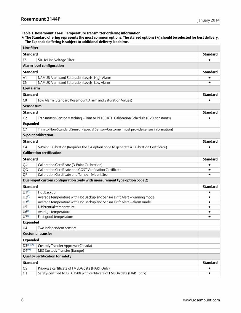
Line filter
Standard Standard
F5 50 Hz Line Voltage Filter ★
Alarm level configuration
Standard Standard
A1 NAMUR Alarm and Saturation Levels, High Alarm ★
CN NAMUR Alarm and Saturation Levels, Low Alarm ★
Low alarm
Standard Standard
C8 Low Alarm (Standard Rosemount Alarm and Saturation Values) ★
Sensor trim
Standard Standard
C2 Transmitter-Sensor Matching – Trim to PT100 RTD Calibration Schedule (CVD constants) ★
Expanded
C7 Trim to Non-Standard Sensor (Special Sensor–Customer must provide sensor information)
5-point calibration
Standard Standard
C4 5-Point Calibration (Requires the Q4 option code to generate a Calibration Certificate) ★
Calibration certification
Standard Standard
Q4 Calibration Certificate (3-Point Calibration) ★
QG Calibration Certificate and GOST Verification Certificate ★
QP Calibration Certificate and Tamper Evident Seal ★
Dual-input custom configuration (only with measurement type option code 2)
Standard Standard
U1(5) Hot Backup ★
U2(5) Average temperature with Hot Backup and Sensor Drift Alert – warning mode ★
U3(6) Average temperature with Hot Backup and Sensor Drift Alert – alarm mode ★
U5 Differential temperature ★
U6(5) Average temperature ★
U7(5) First good temperature ★
Expanded
U4 Two independent sensors
Customer transfer
Expanded
D3(6)(5) Custody Transfer Approval (Canada)D4(6) MID Custody Transfer (Europe)
Quality certification for safety
Standard Standard
QS Prior-use certificate of FMEDA data (HART Only) ★
QT Safety-certified to IEC 61508 with certificate of FMEDA data (HART only) ★
Table 1. Rosemount 3144P Temperature Transmitter ordering information★ The Standard offering represents the most common options. The starred options (★) should be selected for best delivery.__The Expanded offering is subject to additional delivery lead time.
7
Rosemount 3144PJanuary 2014
www.rosemount.com
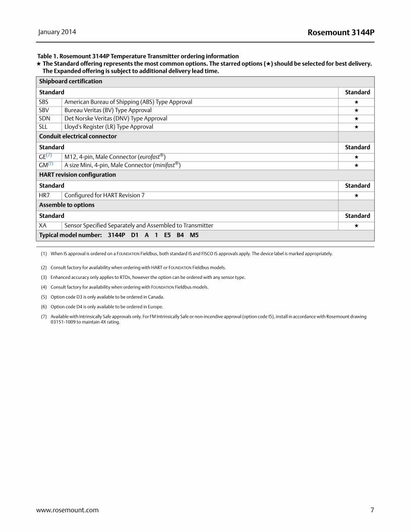
Shipboard certification
Standard Standard
SBS American Bureau of Shipping (ABS) Type Approval ★
SBV Bureau Veritas (BV) Type Approval ★
SDN Det Norske Veritas (DNV) Type Approval ★
SLL Lloyd's Register (LR) Type Approval ★
Conduit electrical connector
Standard Standard
GE(7) M12, 4-pin, Male Connector (eurofast®) ★
GM(7) A size Mini, 4-pin, Male Connector (minifast®) ★
HART revision configuration
Standard Standard
HR7 Configured for HART Revision 7 ★
Assemble to options
Standard Standard
XA Sensor Specified Separately and Assembled to Transmitter ★
Typical model number: 3144P D1 A 1 E5 B4 M5
(1) When IS approval is ordered on a FOUNDATION Fieldbus, both standard IS and FISCO IS approvals apply. The device label is marked appropriately.
(2) Consult factory for availability when ordering with HART or FOUNDATION Fieldbus models.
(3) Enhanced accuracy only applies to RTDs, however the option can be ordered with any sensor type.
(4) Consult factory for availability when ordering with FOUNDATION Fieldbus models.
(5) Option code D3 is only available to be ordered in Canada.
(6) Option code D4 is only available to be ordered in Europe.
(7) Available with Intrinsically Safe approvals only. For FM Intrinsically Safe or non-incendive approval (option code I5), install in accordance with Rosemount drawing 03151-1009 to maintain 4X rating.
Table 1. Rosemount 3144P Temperature Transmitter ordering information★ The Standard offering represents the most common options. The starred options (★) should be selected for best delivery.__The Expanded offering is subject to additional delivery lead time.
8
Rosemount 3144P January 2014
www.rosemount.com
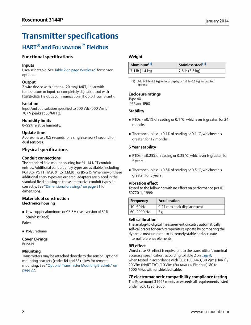
Transmitter specificationsHART® and FOUNDATION™ Fieldbus
Functional specifications
InputsUser-selectable. See Table 2 on page Wireless-9 for sensor options.
Output2-wire device with either 4–20 mA/HART, linear with temperature or input, or completely digital output with FOUNDATION Fieldbus communication (ITK 6.0.1 compliant).
IsolationInput/output isolation specified to 500 Vdc (500 Vrms 707 V peak) at 50/60 Hz.
Humidity limits0–99% relative humidity.
Update timeApproximately 0.5 seconds for a single sensor (1 second for dual sensors).
Physical specifications
Conduit connectionsThe standard field mount housing has ½–14 NPT conduit entries. Additional conduit entry types are available, including PG13.5 (PG11), M20 X 1.5 (CM20), or JIS G ½. When any of these additional entry types are ordered, adapters are placed in the standard field housing so these alternative conduit types fit correctly. See “Dimensional drawings” on page 21 for dimensions.
Materials of constructionElectronics housing
Low-copper aluminum or CF-8M (cast version of 316 Stainless Steel)
Paint
Polyurethane
Cover O-ringsBuna-N
MountingTransmitters may be attached directly to the sensor. Optional mounting brackets (codes B4 and B5) allow for remote mounting. See “Optional Transmitter Mounting Brackets” on page 22.
Weight
Enclosure ratingsType 4XIP66 and IP68
Stability
RTDs: - ±0.1% of reading or 0.1 °C, whichever is greater, for 24 months.
Thermocouples: - ±0.1% of reading or 0.1 °C, whichever is greater, for 12 months.
5 Year stability
RTDs: - ±0.25% of reading or 0.25 °C, whichever is greater, for 5 years.
Thermocouples: - ±0.5% of reading or 0.5 °C, whichever is greater, for 5 years.
Vibration effectTested to the following with no effect on performance per IEC 60770-1, 1999:
Self calibrationThe analog-to-digital measurement circuitry automatically self-calibrates for each temperature update by comparing the dynamic measurement to extremely stable and accurate internal reference elements.
RFI effectWorst case RFI effect is equivalent to the transmitter’s nominal accuracy specification, according toTable 2 on page 9, when tested in accordance with IEC 61000-4-3, 30 V/m (HART) / 20 V/m (HART T/C) /10 V/m (FOUNDATION Fieldbus), 80 to 1000 MHz, with unshielded cable.
CE electromagnetic compatibility compliance testingThe Rosemount 3144P meets or exceeds all requirements listed under IEC 61326: 2006.
Aluminum(1)
(1) Add 0.5 lb (0.2 kg) for local display or 1.0 lb (0.5 kg) for bracket options.
Stainless steel(1)
3.1 lb (1.4 kg) 7.8 lb (3.5 kg)
Frequency Acceleration
10–60 Hz 0.21 mm peak displacement60–2000 Hz 3 g
9
Rosemount 3144PJanuary 2014
www.rosemount.com
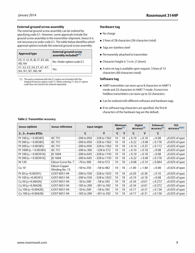
External ground screw assemblyThe external ground screw assembly can be ordered by specifying code G1. However, some approvals include the ground screw assembly in the transmitter shipment, hence it is not necessary to order code G1. The table below identifies which approval options include the external ground screw assembly.
Hardware tag
No charge
2 lines of 28 characters (56 characters total)
Tags are stainless steel
Permanently attached to transmitter
Character height is 1/16-in. (1.6mm)
A wire-on tag is available upon request. 5 lines of 12 characters (60 characters total)
Software tag
HART transmitter can store up to 8 characters in HART 5 mode and 32 characters in HART 7 mode. FOUNDATION Fieldbus transmitters can store up to 32 characters.
Can be ordered with different software and hardware tags.
If no software tag characters are specified, the first 8 characters of the hardware tag are the default.
Table 2. Transmitter accuracy
Approval typeExternal ground screw assembly included?(1)
(1) The parts contained with the G1 option are included with the Integral Protector option code T1. When ordering T1, the G1 option code does not need to be ordered separately.
E5, I1, I2, I5, I6, I7, K5, K6, KB, NA
No–Order option code G1
E1, E2, E3, E4, E7, K1, K7, KA, N1, N7, ND, NF
Yes
Sensor options Sensor reference Input ranges Minimum span(1)
Digital accuracy(2)
Enhanced accuracy(3)
D/A accuracy(4)(5)
2-, 3-, 4-wire RTDs °C °F °C °F °C °F °C
Pt 100 ( = 0.00385) IEC 751 –200 to 850 –328 to 1562 10 18 ± 0.10 ± 0.18 ± 0.08 ±0.02% of spanPt 200 ( = 0.00385) IEC 751 –200 to 850 –328 to 1562 10 18 ± 0.22 ± 0.40 ± 0.176 ±0.02% of spanPt 500 ( = 0.00385) IEC 751 –200 to 850 –328 to 1562 10 18 ± 0.14 ± 0.25 ± 0.112 ±0.02% of spanPt 1000 ( = 0.00385) IEC 751 –200 to 300 –328 to 572 10 18 ± 0.10 ± 0.18 ± 0.08 ±0.02% of spanPt 100 ( = 0.003916) JIS 1604 –200 to 645 –328 to 1193 10 18 ± 0.10 ± 0.18 ± 0.08 ±0.02% of spanPt 200 ( = 0.003916) JIS 1604 –200 to 645 –328 to 1193 10 18 ± 0.22 ± 0.40 ± 0.176 ±0.02% of spanNi 120 Edison Curve No. 7 –70 to 300 –94 to 572 10 18 ± 0.08 ± 0.14 ± 0.064 ±0.02% of span
Cu 10Edison Copper Winding No. 15
–50 to 250 –58 to 482 10 18 ±1.00 ± 1.80 ± 0.08 ±0.02% of span
Pt 50 (=0.00391) GOST 6651-94 –200 to 550 –328 to 1022 10 18 ±0.20 ±0.36 ± 0.16 ±0.02% of spanPt 100 (=0.00391) GOST 6651-94 –200 to 550 –328 to 1022 10 18 ±0.10 ±0.18 ± 0.08 ±0.02% of spanCu 50 (=0.00426) GOST 6651-94 –50 to 200 –58 to 392 10 18 ±0.34 ±0.61 ± 0.272 ±0.02% of spanCu 50 (=0.00428) GOST 6651-94 –185 to 200 –301 to 392 10 18 ±0.34 ±0.61 ± 0.272 ±0.02% of spanCu 100 (=0.00426) GOST 6651-94 –50 to 200 –58 to 392 10 18 ±0.17 ±0.31 ± 0.136 ±0.02% of spanCu 100 (=0.00428) GOST 6651-94 –185 to 200 –301 to 392 10 18 ±0.17 ±0.31 ± 0.136 ±0.02% of span
10
Rosemount 3144P January 2014
www.rosemount.com
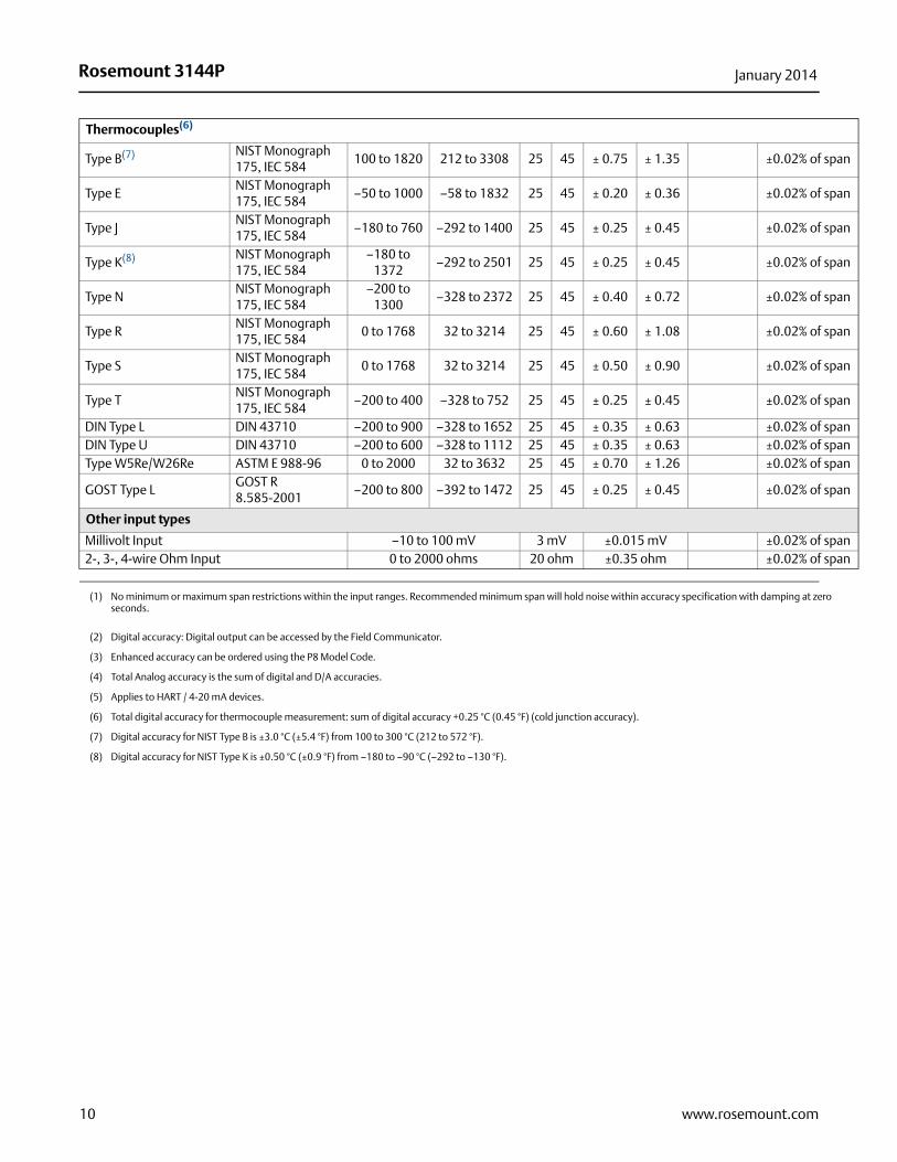
Thermocouples(6)
Type B(7) NIST Monograph 175, IEC 584
100 to 1820 212 to 3308 25 45 ± 0.75 ± 1.35 ±0.02% of span
Type ENIST Monograph 175, IEC 584
–50 to 1000 –58 to 1832 25 45 ± 0.20 ± 0.36 ±0.02% of span
Type JNIST Monograph 175, IEC 584
–180 to 760 –292 to 1400 25 45 ± 0.25 ± 0.45 ±0.02% of span
Type K(8) NIST Monograph 175, IEC 584
–180 to 1372
–292 to 2501 25 45 ± 0.25 ± 0.45 ±0.02% of span
Type NNIST Monograph 175, IEC 584
–200 to 1300
–328 to 2372 25 45 ± 0.40 ± 0.72 ±0.02% of span
Type RNIST Monograph 175, IEC 584
0 to 1768 32 to 3214 25 45 ± 0.60 ± 1.08 ±0.02% of span
Type SNIST Monograph 175, IEC 584
0 to 1768 32 to 3214 25 45 ± 0.50 ± 0.90 ±0.02% of span
Type TNIST Monograph 175, IEC 584
–200 to 400 –328 to 752 25 45 ± 0.25 ± 0.45 ±0.02% of span
DIN Type L DIN 43710 –200 to 900 –328 to 1652 25 45 ± 0.35 ± 0.63 ±0.02% of spanDIN Type U DIN 43710 –200 to 600 –328 to 1112 25 45 ± 0.35 ± 0.63 ±0.02% of spanType W5Re/W26Re ASTM E 988-96 0 to 2000 32 to 3632 25 45 ± 0.70 ± 1.26 ±0.02% of span
GOST Type LGOST R 8.585-2001
–200 to 800 –392 to 1472 25 45 ± 0.25 ± 0.45 ±0.02% of span
Other input types
Millivolt Input –10 to 100 mV 3 mV ±0.015 mV ±0.02% of span2-, 3-, 4-wire Ohm Input 0 to 2000 ohms 20 ohm ±0.35 ohm ±0.02% of span
(1) No minimum or maximum span restrictions within the input ranges. Recommended minimum span will hold noise within accuracy specification with damping at zero seconds.
(2) Digital accuracy: Digital output can be accessed by the Field Communicator.
(3) Enhanced accuracy can be ordered using the P8 Model Code.
(4) Total Analog accuracy is the sum of digital and D/A accuracies.
(5) Applies to HART / 4-20 mA devices.
(6) Total digital accuracy for thermocouple measurement: sum of digital accuracy +0.25 °C (0.45 °F) (cold junction accuracy).
(7) Digital accuracy for NIST Type B is ±3.0 °C (±5.4 °F) from 100 to 300 °C (212 to 572 °F).
(8) Digital accuracy for NIST Type K is ±0.50 °C (±0.9 °F) from –180 to –90 °C (–292 to –130 °F).
11
Rosemount 3144PJanuary 2014
www.rosemount.com
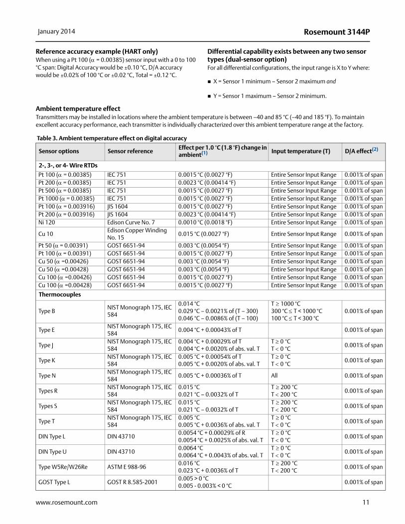
Reference accuracy example (HART only)When using a Pt 100 (= 0.00385) sensor input with a 0 to 100 °C span: Digital Accuracy would be ±0.10 °C, D/A accuracy would be ±0.02% of 100 °C or ±0.02 °C, Total = ±0.12 °C.
Differential capability exists between any two sensor types (dual-sensor option)For all differential configurations, the input range is X to Y where:
X = Sensor 1 minimum – Sensor 2 maximum and
Y = Sensor 1 maximum – Sensor 2 minimum.
Ambient temperature effectTransmitters may be installed in locations where the ambient temperature is between –40 and 85 °C (–40 and 185 °F). To maintain excellent accuracy performance, each transmitter is individually characterized over this ambient temperature range at the factory.
Table 3. Ambient temperature effect on digital accuracy
Sensor options Sensor referenceEffect per 1.0 °C (1.8 °F) change in ambient(1) Input temperature (T) D/A effect(2)
2-, 3-, or 4- Wire RTDs
Pt 100 (= 0.00385) IEC 751 0.0015 °C (0.0027 °F) Entire Sensor Input Range 0.001% of spanPt 200 ( = 0.00385) IEC 751 0.0023 °C (0.00414 °F) Entire Sensor Input Range 0.001% of spanPt 500 ( = 0.00385) IEC 751 0.0015 °C (0.0027 °F) Entire Sensor Input Range 0.001% of spanPt 1000 ( = 0.00385) IEC 751 0.0015 °C (0.0027 °F) Entire Sensor Input Range 0.001% of spanPt 100 (= 0.003916) JIS 1604 0.0015 °C (0.0027 °F) Entire Sensor Input Range 0.001% of spanPt 200 ( = 0.003916) JIS 1604 0.0023 °C (0.00414 °F) Entire Sensor Input Range 0.001% of spanNi 120 Edison Curve No. 7 0.0010 °C (0.0018 °F) Entire Sensor Input Range 0.001% of span
Cu 10Edison Copper Winding No. 15
0.015 °C (0.0027 °F) Entire Sensor Input Range 0.001% of span
Pt 50 ( = 0.00391) GOST 6651-94 0.003 °C (0.0054 °F) Entire Sensor Input Range 0.001% of spanPt 100 ( = 0.00391) GOST 6651-94 0.0015 °C (0.0027 °F) Entire Sensor Input Range 0.001% of spanCu 50 (=0.00426) GOST 6651-94 0.003 °C (0.0054 °F) Entire Sensor Input Range 0.001% of spanCu 50 (=0.00428) GOST 6651-94 0.003 °C (0.0054 °F) Entire Sensor Input Range 0.001% of spanCu 100 (=0.00426) GOST 6651-94 0.0015 °C (0.0027 °F) Entire Sensor Input Range 0.001% of spanCu 100 (=0.00428) GOST 6651-94 0.0015 °C (0.0027 °F) Entire Sensor Input Range 0.001% of span
Thermocouples
Type BNIST Monograph 175, IEC 584
0.014 °C 0.029 °C – 0.0021% of (T – 300)0.046 °C – 0.0086% of (T – 100)
T1000 °C300 °C T < 1000 °C100 °C T < 300 °C
0.001% of span
Type ENIST Monograph 175, IEC 584
0.004 °C + 0.00043% of T 0.001% of span
Type J NIST Monograph 175, IEC 584
0.004 °C + 0.00029% of T0.004 °C + 0.0020% of abs. val. T
T 0°CT 0°C
0.001% of span
Type KNIST Monograph 175, IEC 584
0.005 °C + 0.00054% of T 0.005 °C + 0.0020% of abs. val. T
T 0°CT 0°C
0.001% of span
Type NNIST Monograph 175, IEC 584
0.005 °C + 0.00036% of T All 0.001% of span
Types R NIST Monograph 175, IEC 584
0.015 °C 0.021 °C – 0.0032% of T
T200°CT 200°C
0.001% of span
Types SNIST Monograph 175, IEC 584
0.015 °C 0.021 °C – 0.0032% of T
T200°CT 200°C
0.001% of span
Type TNIST Monograph 175, IEC 584
0.005 °C 0.005 °C + 0.0036% of abs. val. T
T0°CT 0°C
0.001% of span
DIN Type L DIN 437100.0054 °C + 0.00029% of R 0.0054 °C + 0.0025% of abs. val. T
T0°CT 0°C
0.001% of span
DIN Type U DIN 437100.0064 °C 0.0064 °C + 0.0043% of abs. val. T
T0°CT 0°C
0.001% of span
Type W5Re/W26Re ASTM E 988-960.016 °C 0.023 °C + 0.0036% of T
T200°CT 200°C
0.001% of span
GOST Type L GOST R 8.585-20010.005 > 0 °C 0.005 - 0.003% < 0 °C
0.001% of span
12
Rosemount 3144P January 2014
www.rosemount.com
Temperature effects exampleWhen using a Pt 100 ( = 0.00385) sensor input with a 0 to 100 °C span at 30 °C ambient temperature, the following statements would be true:Digital temp effects
D/A effects (HART / 4–20 mA only)%
[0.01% / °C of span] x |(Ambient temp - Calibrated temp)| = D/A Effects
[0.01% / °C x 100] x |(30 - 20)| = 0.01 °C
Worst case error
Digital + D/A + Digital Temp Effects + D/A Effects = 0.10 °C + 0.02 °C + 0.015 °C + 0.01 °C = 0.145 °C
HART / 4–20 mA specifications
Power supplyExternal power supply required. Transmitters operate on 12.0 to 42.4 Vdc transmitter terminal voltage (with 250 ohm load, 18.1 Vdc power supply voltage is required). Transmitter power terminals rated to 42.4 Vdc.
Wiring diagramSee Figure 1 on page 23.
AlarmsCustom factory configurations of alarm and saturation levels are available for valid values with option code C1. These values can also be configured in the field using a Field Communicator.
Transient protection (option code T1)The transient protector helps to prevent damage to the transmitter from transients induced on the loop wiring by lightning, welding, heavy electrical equipment, or switch gears. The transient protection electronics are contained in an add-on assembly that attaches to the standard transmitter terminal block. The external ground lug assembly (code G1) is included with the Transient Protector. The transient protector has been tested per the following standard:
IEEE C62.41-1991 (IEEE 587)/ Location Categories B3.6kV/3kA peak (1.2 � 50 S Wave 8 � 20 S Combination Wave) 6kV/0.5kA peak (100 kHz Ring Wave)EFT, 4kVpeak, 2.5kHz, 5*50nS
Loop resistance added by protector: 22 ohms max.
Nominal clamping voltages: 90 V (common mode), 77 V (normal mode)
Local displayOptional five-digit LCD display includes 0–100% bar graph. Digits are 0.4 inches (8 mm) high. Display options include engineering units (°F, °C, °R, K, ohms, and millivolts), percent, and milliamperes. The display can also be set to alternate between engineering units/milliamperes, Sensor 1/Sensor 2, Sensor 1/Sensor 2/Differential Temperature, and Sensor 1/Sensor2/Average Temperature. All display options, including the decimal point, may be reconfigured in the field using a Field Communicator or AMS.
Turn-on timePerformance within specifications is achieved less than 6 seconds after power is applied to the transmitter when the damping value is set to 0 seconds.
Power supply effectLess than ±0.005% of span per volt.
Other input types
Millivolt Input 0.00025 mV Entire Sensor Input Range 0.001% of span2-, 3-, 4-wire Ohm Input 0.007 Entire Sensor Input Range 0.001% of span
(1) Change in ambient is in reference to the calibration temperature of the transmitter (20 °C [68 °F]).
(2) Applies to HART / 4-20 mA devices.
Sensor options Sensor referenceEffect per 1.0 °C (1.8 °F) change in ambient(1) Input temperature (T) D/A effect(2)
0.0015 CC------- x 30 C 20 C– 0.015 C=
13
Rosemount 3144PJanuary 2014
www.rosemount.com
SIS safety transmitter failure valuesIEC 61508 Safety Certified SIL 2 and SIL 3 Claim Limit
Temperature limits
Field communicator connectionsField Communicator connections are permanently fixed to power/signal block.
Failure modeThe Rosemount 3144P features software and hardware failure mode detection. An independent circuit is designed to provide backup alarm output if the microprocessor hardware or software fails. The alarm level is user-selectable using the failure mode switch. If failure occurs, the position of the hardware switch determines the direction in which the output is driven (HIGH or LOW). The switch feeds into the digital-to-analog (D/A) converter, which drives the proper alarm output even if the microprocessor fails. The values at which the transmitter drives its output in failure mode depends on whether it is configured to standard, or NAMUR-compliant (NAMUR recommendation NE 43) operation. The values for standard and NAMUR-compliant operation are as follows:
Table 4. Operation parameters
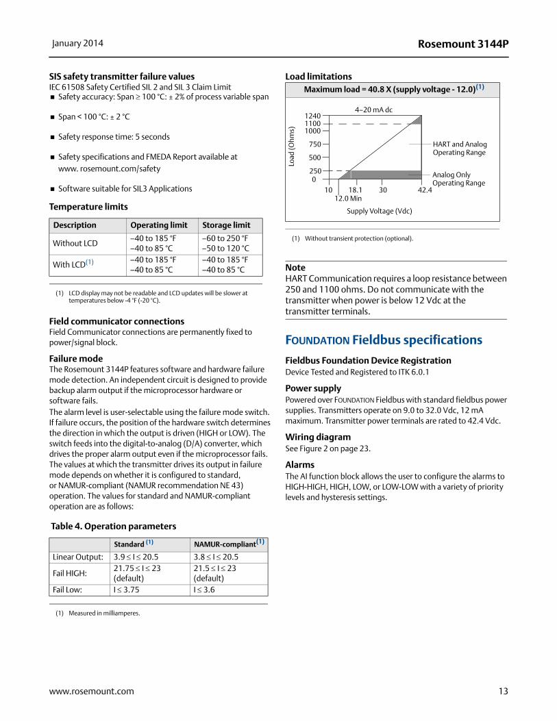
Load limitations
NoteHART Communication requires a loop resistance between 250 and 1100 ohms. Do not communicate with the transmitter when power is below 12 Vdc at the transmitter terminals.
FOUNDATION Fieldbus specifications
Fieldbus Foundation Device RegistrationDevice Tested and Registered to ITK 6.0.1
Power supply Powered over FOUNDATION Fieldbus with standard fieldbus power supplies. Transmitters operate on 9.0 to 32.0 Vdc, 12 mA maximum. Transmitter power terminals are rated to 42.4 Vdc.
Wiring diagramSee Figure 2 on page 23.
AlarmsThe AI function block allows the user to configure the alarms to HIGH-HIGH, HIGH, LOW, or LOW-LOW with a variety of priority levels and hysteresis settings.
Safety accuracy: Span 100 °C: ± 2% of process variable span
Span < 100 °C: ± 2 °C
Safety response time: 5 seconds
Safety specifications and FMEDA Report available at www. rosemount.com/safety
Software suitable for SIL3 Applications
Description Operating limit Storage limit
Without LCD–40 to 185 °F–40 to 85 °C
–60 to 250 °F–50 to 120 °C
With LCD(1)
(1) LCD display may not be readable and LCD updates will be slower at temperatures below -4 °F (-20 °C).
–40 to 185 °F–40 to 85 °C
–40 to 185 °F–40 to 85 °C
Standard (1)
(1) Measured in milliamperes.
NAMUR-compliant(1)
Linear Output: 3.9 I 20.5 3.8 I 20.5
Fail HIGH:21.75 I 23 (default)
21.5 I 23 (default)
Fail Low: I 3.75 I 3.6
Maximum load = 40.8 X (supply voltage - 12.0)(1)
(1) Without transient protection (optional).
1240
1000
750
2500
1012.0 Min
18.1 30 42.4
Supply Voltage (Vdc)
HART and Analog Operating Range
4–20 mA dc
Load
(Ohm
s)
500
1100
Analog Only Operating Range
14
Rosemount 3144P January 2014
www.rosemount.com
Transient protection (option code T1)The transient protector helps to prevent damage to the transmitter from transients induced on the loop wiring by lightning, welding, heavy electrical equipment, or switch gears. The transient protection electronics are contained in an add-on assembly that attaches to the standard transmitter terminal block. The transient terminal block is not polarity insensitive. The transient protector has been tested to the following standard:
IEEE C62.41-1991 (IEEE 587)/ Location Categories B3.6kV/3kA peak (1.2 � 50 S Wave 8 � 20 S Combination Wave)6kV/0.5kA peak (100 kHz Ring Wave)EFT, 4kVpeak, 2.5kHz, 5*50nS
Loop resistance added by protector: 22 ohms maximum
Nominal clamping voltages: 90 V (common mode), 77 V (normal mode)
Diagnostics suite for FOUNDATION Fieldbus (option code D01)The 3144P Diagnostics Suite for FOUNDATION Fieldbus provides advanced functionality in the form of Statistical Process Monitoring (SPM), a thermocouple Diagnostic, and Sensor Drift Alert. SPM technology calculates the mean and standard deviation of the process variable and makes them available to the user. This may be used to detect abnormal process situations.The Thermocouple Diagnostic enables the 3144P to measure and monitor the resistance of thermocouple loops in order to detect drift or changing wiring connections.Sensor Drift Alert allows the user to monitor the difference in measurement between two sensors installed in one process point. A change in this differential value may indicate drifting sensors.
Local displayDisplays all DS_65 measurements in the Transducer and Function Blocks including Sensor 1, Sensor 2, differential, and terminal temperatures. The display alternates up to four selected items. The meter can display up to five digits in engineering units (°F, °C, °R, K, , and millivolts). Display settings are configured at the factory according to the transmitter configuration (standard or custom). These settings can be reconfigured in the field using a Field Communicator or DeltaV. In addition, the LCD provides the ability to display DS_65 parameters from other devices. In addition to the configuration of the meter, sensor diagnostic data is displayed. If the measurement status is Good, the measured value is shown. If the measurement status is Uncertain, the status indicating uncertain is shown in addition to the measured value. If the measurement status is Bad, the reason for the bad measurement is shown. Note: When ordering a spare electronics module assembly, the LCD transducer block will display the default parameter.
Turn-on timePerformance within specifications is achieved less than 20 seconds after power is applied to the transmitter when the damping value is set to 0 seconds.
StatusThe device is compliant to NAMUR NE 107, ensuring consistent, reliable and standardized device diagnostic information.The new standard is designed to improve the way device status and diagnostic information is communicated to operators and maintenance personnel in order to increase productivity and reduce costs.If self-diagnostics detect a sensor burnout or a transmitter failure, the status of the measurement will be updated accordingly. The status may also send the PID output to a safe value.
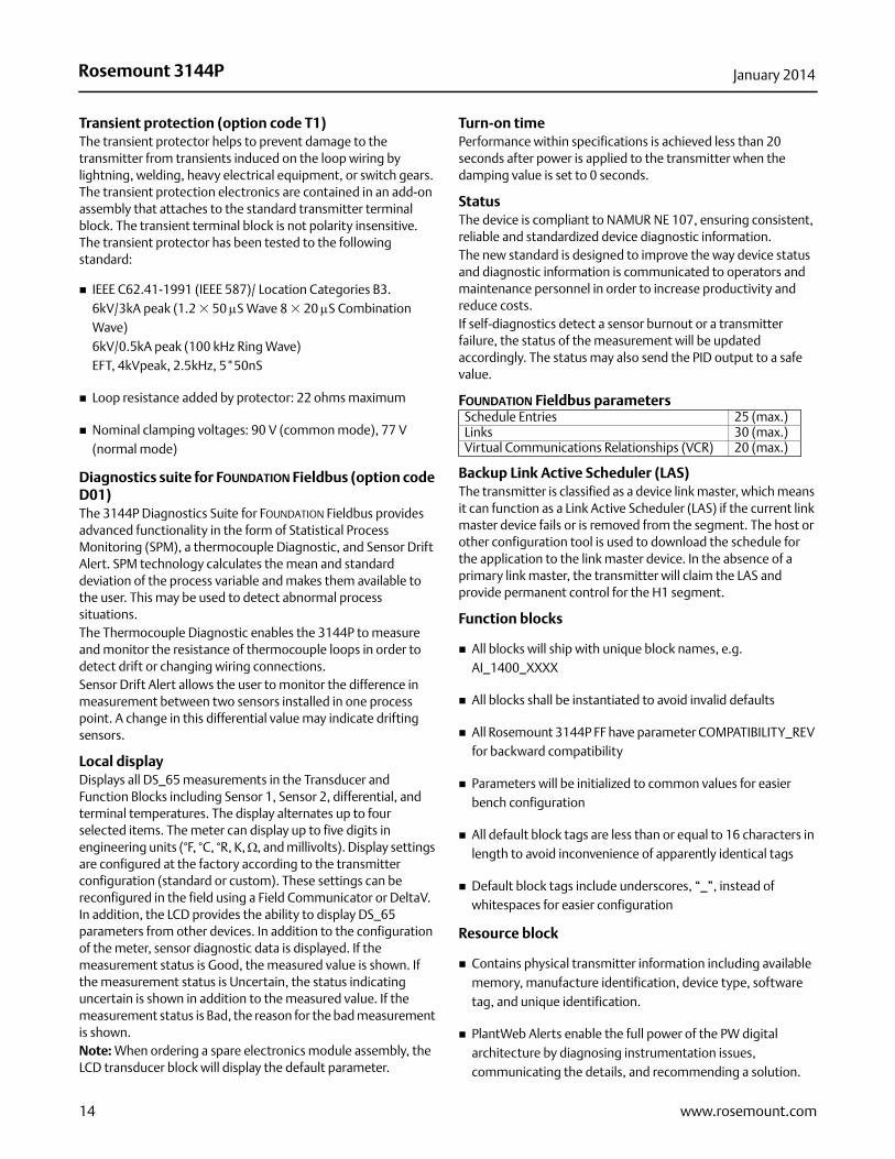
FOUNDATION Fieldbus parameters
Backup Link Active Scheduler (LAS)The transmitter is classified as a device link master, which means it can function as a Link Active Scheduler (LAS) if the current link master device fails or is removed from the segment. The host or other configuration tool is used to download the schedule for the application to the link master device. In the absence of a primary link master, the transmitter will claim the LAS and provide permanent control for the H1 segment.
Function blocks
All blocks will ship with unique block names, e.g. AI_1400_XXXX
All blocks shall be instantiated to avoid invalid defaults
All Rosemount 3144P FF have parameter COMPATIBILITY_REV for backward compatibility
Parameters will be initialized to common values for easier bench configuration
All default block tags are less than or equal to 16 characters in length to avoid inconvenience of apparently identical tags
Default block tags include underscores, “_”, instead of whitespaces for easier configuration
Resource block
Contains physical transmitter information including available memory, manufacture identification, device type, software tag, and unique identification.
PlantWeb Alerts enable the full power of the PW digital architecture by diagnosing instrumentation issues, communicating the details, and recommending a solution.
Schedule Entries 25 (max.)Links 30 (max.)Virtual Communications Relationships (VCR) 20 (max.)
15
Rosemount 3144PJanuary 2014
www.rosemount.com
Transducer block
Contains the actual temperature measurement data, including sensor 1, sensor 2, and terminal temperature.
Includes information about sensor type and configuration, engineering units, linearization, range, damping, and diagnostics.
Device Revision 3 and above includes Hot Backup functionality in the transducer block
LCD block (when an LCD display is used)
Configures the local display.
Analog input (AI)
Processes the measurement and makes it available on the fieldbus segment.
Allows filtering, engineering unit, and alarm changes.
All devices ship with the AI blocks scheduled, meaning no configuration is needed if the factory default channels are used
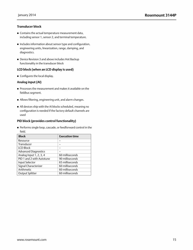
PID block (provides control functionality)
Performs single loop, cascade, or feedforward control in the field.
Block Execution time
Resource –Transducer –LCD Block –Advanced Diagnostics –Analog Input 1, 2, 3, 4 60 millisecondsPID 1 and 2 with Autotune 90 millisecondsInput Selector 65 millisecondsSignal Characterizer 60 millisecondsArithmetic 60 millisecondsOutput Splitter 60 milliseconds