rosemount 9901 chamber for process level instrumentation ... · rosemount 9901 chamber design the...
TRANSCRIPT

Product Data Sheet00813-0100-4601, Rev. AAJanuary 2009 Rosemount 9901
www.rosemount.com
• Allows external mounting of process level instrumentation
• Enables live maintenance
• Designed to ASME B31.3
• Pressure Equipment Directive (PED) compliant
• Used worldwide by major industries:Power, Petro-Chemical, Refining, Oil & gas, Chemical and Process Steam Raising sectors
• Ideal for critical area and general purpose applications
• Variety of process connections and optional drain and vent connections
• More than 50 years of experience in designing and manufacturing chambers in accordance with international codes
• For use in applications up toASME B16.5 Class 1500 and EN1092 PN250
• Available in carbon steel and stainless steel
• Custom design service available
Contents
Overview of the Rosemount 9901 . . . . . . . . . . . . . . . . . . . . . . . . . . . . . . . . . . . . . . . page 2
Available Instrumentation . . . . . . . . . . . . . . . . . . . . . . . . . . . . . . . . . . . . . . . . . . . . . page 4
Chambers Technical Specification. . . . . . . . . . . . . . . . . . . . . . . . . . . . . . . . . . . . . . . page 6
Dimensional Drawings. . . . . . . . . . . . . . . . . . . . . . . . . . . . . . . . . . . . . . . . . . . . . . . . page 7
Ordering Information . . . . . . . . . . . . . . . . . . . . . . . . . . . . . . . . . . . . . . . . . . . . . . . . page 12
Rosemount 9901 Chamber for Process Level Instrumentation

Product Data Sheet00813-0100-4601, Rev. AA
January 2009Rosemount 9901
2
Overview of the Rosemount 9901
INTRODUCTIONThe Rosemount 9901 is a self-contained chamber for externally mounting the Rosemount range of process level instruments to a vessel (Figure 1).
Figure 1.
Externally mounting an instrument in a chamber means it can be isolated for routine maintenance while keeping the plant operational. It is also useful for in-tank restrictions that do not allow mounting of the instrument in a vessel.
This approach offers many advantages when solving application challenges:
In-tank constraints:
• agitator
• heat exchanger
• internal structures
Isolation of instrument:
• live maintenance
• safety
• hazardous liquids
• high pressure
• high temperature
Turbulent vessel conditions:
• chamber acts as a stilling tube
CHAMBERThe chamber, also known as a cage or bridle, houses the liquid being measured and the instrument’s sensing element.
There are two process connections on the body of the chamber which allow mounting to the vessel.
Figure 2 shows the most common configurations.
Figure 2.
NOTE:When ordering, specify the center-to-center dimension in feet and inches, or meters and millimeters (see dimension B in Dimensional Drawings on page 7.)
The instrument is mounted on top of the chamber through the flanged or threaded instrument connection. A threaded version is available for the vertical float level switch. Summaries of the available instruments can be found on page 4.
Standard materials are carbon steel and stainless steel with other materials available upon request.
Standard Design:Side-and-Bottom
Standard Design:Side-and-Side
Cen
ter-
to-c
ente
r D
imen
sio
n
Cen
ter-
to-c
en
ter
Dim
ensi
on
Mea
suri
ng
R
an
ge
Mea
suri
ng
R
ang
eThe Rosemount 5300 is shown here. For all available instruments, see Available Instrumentation on page 4

Product Data Sheet00813-0100-4601, Rev. AAJanuary 2009
3
Rosemount 9901
Chamber Design
The Rosemount 9901 chamber is designed to the ASME B31.3 standard, and is Pressure Equipment Directive (PED) compliant.
Weld neck flanges and full penetration welds in accordance with EN ISO 15614-1:2004 and ASME Boiler and Pressure Vessel Code Section IX are used through out. All welders are qualified toEN 287-1:2004 and ASME Boiler and Pressure Vessel Code Section IX.
All construction materials have full traceability in accordance with the EN 10204 type 3.1 certificate.
Every 9901 is hydro-tested as standard. A full range of non destructive testing (NDT) is also available – see page 16.
There are two designs available: the Standard Design and T-piece Design. Both designs are outlined below.
Standard Design
With the standard design, the process connections are welded directly onto the chamber body. This keeps the number of welds to a minimum for increased safety (see Figure 3).
The standard design is available with a 3-in. (80-mm) chamber body and 1-in. (25-mm) process connection, or a 4-in. (100-mm) chamber body with 1-in. (25-mm), 1½-in. (40-mm), or 2-in. (50-mm) process connections.
Pressure ratings up to and including ASME B16.5 Class 1500 and EN1092 PN250 are available.
Figure 3.
T-Piece Design
In instances when a 1½-in. (40-mm) or 2-in. (50-mm) process connection is required on a 3-in. (80-mm) chamber, the T-Piece design is used (Figure 4.) Unequal T’s are used so the larger process connections can fit on the smaller chamber body. Pressure ratings of up to and including ASME B16.5 Class 600 and EN1092 PN100 are available.
Figure 4.
Figure 5.
NOTE:The T-Piece design requires more components, and so there are more welded joints (see Figure 5.)The standard design should be regarded as the first choice unless it is necessary to have 1½-in. (40-mm) or 2-in. (50-mm) process connections on a 3-in. (80-mm) chamber.
Drain and Vent (Optional)
A drain allows liquid to be drained away, and allows maintenance of the instrument. It is always specified for a side-and-side chamber.
A vent is optional and allows gas in the upper zone above the liquid to be vented off.
Both the drain and vent are available as threaded or flanged in a variety of sizes. Other options are available upon request.
NOTE:It is common practice to mount a valve to control the opening and closing of a drain or vent. A selection of valves are available upon request.
WeldNeck Flanges
FullPenetration
Welds
T-Piece Design:Side-and-Bottom
T-Piece Design:Side-and-Side
Cen
ter-
to-c
ente
r D
imen
sio
n
Cen
ter-
to-c
ente
r D
ime
nsi
on
Mea
suri
ng
R
ang
e
Mea
su
rin
g
Ran
ge
The Rosemount 5300 is shown here. For all available instruments, see Available Instrumentation on page 4
WeldNeck Flanges
FullPenetration
Welds
FullPenetrationWelds

Product Data Sheet00813-0100-4601, Rev. AA
January 2009Rosemount 9901
4
Available InstrumentationThe following are compatible with the chambers and are ordered separately. For full details, refer to the relevant product data sheets available from www.rosemount.com.
Rosemount 3300 SeriesGWR Transmitter
The Rosemount 3300 Series is a smart, two-wire, loop-powered level and interface transmitter, based on guided wave radar technology. The 3300 provides reliable liquid measurements, even in severe conditions. 3300 Series transmitters are an ideal choice for interface measurements in chambers.
• Top mounting using vertical chamber 9901G
• Continuous level, contents, or interface measurement
• MultiVariable™ output allows choice of variable
• Alternative to displacer technology
Figure 6.
Rosemount 5300 SeriesGWR Transmitter
The Rosemount 5300 Series is a premium two-wire transmitter that uses guided wave radar for challenging liquid level and interface measurements.
This best-in-class process radar instrument delivers everything you would expect – superior reliability, state-of-the-art safety features, and effortless handling.
• Top mounting using vertical chamber 9901G
• Continuous level, contents (volume),or interface measurement
• MultiVariable output allows choice of variable
• Longer range than Rosemount 3300 Series GWR transmitter
• Wide application flexibility for a range ofprocess medias and vessel structures
• Alternative to displacer technology
Figure 7.
Rosemount 3300 Series GWR Transmitter
Rosemount 5300 Series GWR Transmitter

Product Data Sheet00813-0100-4601, Rev. AAJanuary 2009
5
Rosemount 9901
Mobrey Vertical Float Level Switch
Float operated liquid point level switches may be used in almost any application.
• Top mounting using vertical chamber 9901V
• Point level liquid measurement
• Electrical switching
• Tough and rugged design for a long life inaggressive environments
• Operates in almost any liquid at highpressures and temperatures
• Widely used and certified formarine applications
Figure 8.
Mobrey MLT Displacer Level Transmitter
In harsh operating conditions where high pressure and temperatures preclude other instrumentation, stable measurements are made with the displacer level transmitter.
• Top mounting using vertical chamber 9901D
• Continuous level, contents or interface measurement
• Two-wire 24V direct current loop powered
• 4–20mA output, HART digital communications
• Fast and simple calibration in tank
• Not available for use in The Americas
Figure 9.
Mobrey Vertical Float Level Switch Mobrey MLT Displacer Level Transmitter

Product Data Sheet00813-0100-4601, Rev. AA
January 2009Rosemount 9901
6
Chambers Technical Specification
MATERIALS OF CONSTRUCTIONOnly materials suitable for pressure use and certified to ASME B31.3 are used in the construction of chambers. Other materials are available to special order.
Table 1. Chamber Materials
PRESSURE RATINGSTable 2. Maximum Pressure Ratings for 9901 Chambers with Alloy Steel Bolting – PSI and Bar
TEMPERATURE RATINGSTable 3. Chamber Temperature Ratings
Component Carbon Steel Stainless Steel
Instrument Mounting Flange ASTM A105 ASTM A182 F316/F316L
Chamber Body Tube ASTM A106 Grade B ASTM A312 TP316/TP316L
Chamber End Cap ASTM A105 ASTM A182 F316/F316L
Process Flange / Fitting ASTM A105 ASTM A182 F316/F316L
T-Pieces and Reducers ASTM A234 WPB ASTM A403 WP316/WP316L–S
Standard Alloy Steel Studbolts ASTM A193 B7 ASTM A320 L7
Standard Alloy Steel Nuts ASTM A194 2H ASTM A194 Grade 7 + S3
Stainless Studbolts (maximum PN40/Class 300) ASTM A193 B8M Cl 1 ASTM A193 B8M Cl 1
Stainless Nuts (maximum PN40/Class 300) ASTM A194 Grade 8M ASTM A194 Grade 8M
Stainless Studbolts (maximum PN100/Class 600) ASTM A193 B8M Cl 2 ASTM A193 B8M Cl 2
Stainless Nuts (maximum PN100/Class 600) ASTM A194 Grade 8M ASTM A194 Grade 8M
Chamber Rating (1)
(1) When using the optional stainless steel bolting, see Instrument Bolting on page 15.
Carbon Steel Chamber Stainless Steel Chamber
PSI (68 F) Bar (20 C) PSI (752 F) Bar (400 C) PSI (68 F) Bar (20 C) PSI (752 F) Bar (400 C)
ASME B16.5 Class 150 285 19.6 95 6.5 275 19 95 6.5
ASME B16.5 Class 300 740 51.1 505 34.7 720 49.6 425 29.4
ASME B16.5 Class 600 1480 102.1 1015 69.4 1440 99.3 855 58.9
ASME B16.5 Class 900 2220 153.2 1520 104.2 2160 148.9 1280 88.3
ASME B16.5 Class 1500 3705 255.3 2517 173.6 3600 248.2 2135 147.2
EN1092 PN16 232 16 137 9.5 227 15.7 134 9.3
EN1092 PN25 362 25 214 14.8 356 24.6 211 14.6
EN1092 PN40 580 40 345 23.8 569 39.3 339 23.4
EN1092 PN63 913 63 543 37.5 899 62 536 37
EN1092 PN100 1450 100 862 59.5 1427 98.4 851 58.7
EN1092 PN160 2320 160 1380 95.2 2291 158 1361 93.9
EN1092 PN250 3625 250 2157 148.8 3567 246 2132 147
Material Chamber Temperature Range (1)
(1) When using the optional stainless steel bolting, see Instrument Bolting on page 15.
Carbon Steel Chamber 14 to 752F (–10 to 400 C)
Stainless Steel Chamber –148 to 752F (–100 to 400 C)

Product Data Sheet00813-0100-4601, Rev. AAJanuary 2009
7
Rosemount 9901
Dimensional Drawings
STANDARD DESIGN
Side-and-Side Chambers
Side-and-Bottom Chambers
Note:This chamber is available for Instrument Type Codes D, V, and G. See “Instrument Type” on page 12 for an explanation of the codes.Dimensions A, C, D, and E are in the tables on pages 8 to 9. Specify center-to-center dimension B when ordering.
Optional Vent(Flanged, Threaded, or
Socket Weld)
Process Connection(Flanged, Threaded, or Socket Weld)
A
Drain(Flanged, Threaded or
Socket Weld)
InstrumentConnection(Flanged)
InstrumentConnection(Threaded)
Optional Vent(Flanged,
Threaded, orSocket Weld)
Process Connection(Flanged, Threaded, or Socket Weld)
A
Drain(Flanged, Threaded, or
Socket Weld)D1
C2
B B
D2
C1
E
D1
C2
D2
C1
E
2 in.(50mm)
2 in.(50mm)
Note:This chamber design is available for Instrument Type Codes D, V, and G. See “Instrument Type” on page 12 for an explanation of the codes.Dimensions A, D, and E are in the tables on pages 8 to 9. Specify center-to-center dimension B when ordering.
Process Connection(Flanged, Threaded, or
Socket Weld)
Process Connection(Flanged, Threaded, or Socket Weld)
Optional Vent(Flanged,
Threaded, orSocket Weld) A
InstrumentConnection(Flanged)
InstrumentConnection(Threaded)
Process Connection(Flanged, Threaded, or
Socket Weld)
Optional Vent(Flanged, Threaded, or
Socket Weld)
Process Connection(Flanged, Threaded, or Socket Weld)
B
A
B
D1
D2
E
D1
D2
E
2 in.(50mm)
2 in.(50mm)

Product Data Sheet00813-0100-4601, Rev. AA
January 2009Rosemount 9901
8
Table 4. Dimension A for Side-and-Side and Side-and-Bottom Chamber
Table 5. Dimensions C1 and C2 for Side-and-Side Chamber
Table 6. Dimension D1 for Side-and-Side and Side-and-Bottom Chamber (Flanged Process Connections)
InstrumentConnections
InstrumentType Code (1)
(1) See “Instrument Type” on page 12 for explanation of code.
3-in. (80-mm) DN80 Chamber 4-in. (100-mm) DN100 Chamber
No Vent Fitted Vent Fitted No Vent Fitted Vent Fitted
In. mm In. mm In. mm In. mm
ASME B16.5 Class 150
RF D 15.75 400 15.75 400 15.75 400 15.75 400
RF / RTJ V 7.87 / 7.56 200 / 192 9.84 / 9.53 250 / 242 7.87 / 7.56 200 / 192 9.84 / 9.53 250 / 242
RF G 10.83 275 10.83 275 10.83 275 10.83 275
ASME B16.5 Class 300
RF D 15.75 400 15.75 400 15.75 400 15.75 400
RF / RTJ V 7.68 / 7.24 195 / 184 9.65 / 9.21 245 / 234 7.56 / 7.13 192 / 181 9.53 / 9.09 242 / 231
RF G 10.83 275 10.83 275 10.83 275 10.83 275
ASME B16.5 Class 600
RF D 15.75 400 15.75 400 15.75 400 15.75 400
RF / RTJ V – – – – 7.05 / 6.85 179 / 174 9.02 / 8.82 229 / 224
RF G 10.83 275 10.83 275 10.83 275 10.83 275
ASME B16.5 Class 900 or Class 1500
RF D 15.75 400 15.75 400 15.75 400 15.75 400
RF V – – – – – – – –
RF G 10.83 275 10.83 275 10.83 275 10.83 275
EN 1092 PN16 RF D 15.75 400 15.75 400 15.75 400 15.75 400
RF V 8.03 204 10.00 254 8.03 204 10.00 254
RF G 10.83 275 10.83 275 10.83 275 10.83 275
EN1092 PN25 orEN1092 PN40
RF D 15.75 400 15.75 400 15.75 400 15.75 400
RF V 7.87 200 9.84 250 7.87 200 9.84 250
RF G 10.83 275 10.83 275 10.83 275 10.83 275
EN1092 PN63 RF D 15.75 400 15.75 400 15.75 400 15.75 400
RF V – – – – 7.56 192 9.53 242
RF G 10.83 275 10.83 275 10.83 275 10.83 275
EN1092 PN100 RF D 15.75 400 15.75 400 15.75 400 15.75 400
RF V – – – – 7.32 186 9.29 236
RF G 10.83 275 10.83 275 10.83 275 10.83 275
EN1092 PN160 orEN1092 PN250
RF D 15.75 400 15.75 400 15.75 400 15.75 400
RF V – – – – – – – –
RF G 10.83 275 10.83 275 10.83 275 10.83 275
Threaded / SW – V 6.30 160 6.30 160 6.30 160 6.30 160
DrainConnections
InstrumentType Code(1)
(1) See “Instrument Type” on page 12 for further information.
3-in. (80-mm) DN80 Chamber 4-in. (100-mm) DN100 Chamber
In. mm In. mm
Dimension C1:SW/Threaded Drain or No Drain
D and V 6.30 160 6.30 160
G 11.42 290 11.42 290
Dimension C2:Flanged Drain
D and V 9.45 240 9.45 240
G 14.57 370 14.57 370
Flanged ProcessConnections
3-in. (80-mm) DN80 Chamber 4-in. (100-mm) DN100 Chamber
In. mm In. mm In. mm In. mm In. mm In. mm
ASME B16.5 (1) Class 150 Class 300 Class 600 Class 150 Class 300 Class 600
1 in. RF 3.86 98 4.09 104 4.37 111 4.33 110 4.61 117 4.84 123
RTJ 4.06 103 4.33 110 4.37 111 4,57 116 4.84 123 4.84 123
11/2 in. RF – – – – – – 4.53 115 4.76 121 5.12 130
RTJ – – – – – – 4.76 121 5.00 127 5.12 130
2 in. RF – – – – – – 4.49 114 4.72 120 5.20 132
RTJ – – – – – – 4.72 120 4.96 126 5.20 132
Class 900 Class 1500 Class 900 Class 1500
1 in. RF 4.80 122 4.80 122 5.31 135 5.31 135
RTJ 4.80 122 4.80 122 5.31 135 5.31 135
Continued on the next page

Product Data Sheet00813-0100-4601, Rev. AAJanuary 2009
9
Rosemount 9901
Table 7. Dimension D2 for Side-and-Side and Side-and-Bottom Chamber (Threaded or Socket Weld Connections)
Table 8. Dimension E for Side-and-Side and Side-and-Bottom Chamber
11/2 in. RF – – – – 5.63 143 5.63 143
RTJ – – – – 5.63 143 5.63 143
2 in. RF – – – – 6.34 161 6.34 161
RTJ – – – – 6.34 161 6.34 161
EN1092 (PN) (1) EN PN16 EN PN25 EN PN40 EN PN16 EN PN25 EN PN40
1 in. RF 3.23 82 3.23 82 3.23 82 3.78 96 3.78 96 3.78 96
11/2 in. RF – – – – – – 3.82 97 3.82 97 3.82 97
2 in. RF – – – – – – 3.74 95 3.86 98 3.86 98
EN PN63/PN100 EN PN160 EN PN250 EN PN63/100 EN PN160 EN PN250
1 in. RF 3.98 101 3.98 101 4.25 108 4.49 114 4.49 114 4.76 121
11/2 in. RF – – – – – – 4.49 114 4.57 116 5.20 132
2 in. RF – – – – – – 4.41/4.7 113/119 4.96 126 5.35 136
(1) RF = Raised Face flange. RTJ = Ring Type Joint flange.
Threaded or SW Process Connections
3-in. (80-mm) DN80 Chamber 4-in. (100-mm) DN100 Chamber
In. mm In. mm
1 in. (25 mm) 3.74 95 4.21 107
VentConnections
3-in. (80-mm) DN80 Chamber 4-in. (100-mm) DN100 Chamber
In. mm In. mm In. mm In. mm In. mm In. mm
ASME B16.5 (1)
(1) RF = Raised Face flange. RTJ = Ring Type Joint flange.
Class 150 Class 300 Class 600 Class 150 Class 300 Class 6001/2 in. RF 3.62 92 3.78 96 4.06 103 4.09 104 4.29 109 4.53 115
RTJ – – 3.94 100 4.02 102 – – 4.41 112 4.45 1133/4 in. RF 3.78 96 3.98 101 4.25 108 4.29 109 4.49 114 4.72 120
RTJ – – 4.17 106 4.25 108 – – 4.65 118 4.69 119
1 in. RF 3.86 98 4.09 104 4.37 111 4.33 110 4.57 116 4.84 123
RTJ 4.06 103 4.33 110 4.37 111 4.57 116 4.84 123 4.84 123
Class 900 Class 1500 Class 900 Class 15001/2 in. RF 4.37 111 4.37 111 4.84 123 4.84 123
RTJ 4.37 111 4.37 111 4.80 122 4.80 1223/4 in. RF 4.72 120 4.72 120 5.24 133 5.24 133
RTJ 4.72 120 4.72 120 5.20 132 5.20 132
1 in. RF 4.80 122 4.80 122 5.31 135 5.31 135
RTJ 4.80 122 4.80 122 5.31 135 5.31 135
EN1092 (PN) (1) PN16 PN25 PN40 PN16 PN25 PN401/2 in. RF 3.19 81 3.19 81 3.19 81 3.70 94 3.70 94 3.70 943/4 in. RF 3.27 83 3.27 83 3.27 83 3.78 96 3.78 96 3.78 96
1 in. RF 3.23 82 3.23 82 3.23 82 3.78 96 3.78 96 3.78 96
PN63/PN100 PN160 PN250 PN63/100 PN160 PN2501/2 in. RF 3.50 89 3.50 89 4.09 104 3.98 101 3.98 101 4.57 1163/4 in. RF 3.62 92 – – – – 4.09 104 – – – –
1 in. RF 3.98 101 3.98 101 4.25 108 4.49 114 4.49 114 4.76 121
Non-Flanged NPT/BSPT Socket Weld NPT/BSPT Socket Weld1/2 in., 3/4 in, and 1 in. 3.74 95 3.74 95 4.21 107 4.21 107
Flanged ProcessConnections
3-in. (80-mm) DN80 Chamber 4-in. (100-mm) DN100 Chamber
In. mm In. mm In. mm In. mm In. mm In. mm
E E E E
A
B B
A A A
B B
D2
D1
D2
D1
D2
D1
D2
D1
C1C2
C1C2

Product Data Sheet00813-0100-4601, Rev. AA
January 2009Rosemount 9901
10
T-PIECE DESIGN
Side-and-Side and Side-and-Bottom Chambers
Table 9. Dimension A for T-Piece Side-and-Side and Side-and-Bottom Chamber
Table 10. Dimension C1 for T-Piece Side-and-Side Chamber
Table 11. Dimension C2 for T-Piece Side-and-Side Chamber
FlangedInstrumentConnections (1)
(1) RF = Raised Face flange. RTJ = Ring Type Joint flange.
InstrumentType Code (2)
(2) See “Instrument Type” on page 12 for explanation of code.
3-in. (80-mm) DN80 Chamber
No Vent Fitted Vent Fitted
In. mm In. mm
ASMEB16.5Class 150
RF D 15.75 400 15.75 400
RF/RTJ V 6.10 / 6.38 155 / 162 10.43 / 10.70 265 / 272
RF G 10.83 275 10.83 275
ASMEB16.5Class 300
RF D 15.75 400 15.75 400
RF/RTJ V 6.50 / 6.81 165 / 173 10.83 / 11.14 275 / 283
RF G 10.83 275 10.83 275
ASMEB16.5Class 600
RF D 15.75 400 15.75 400
RF/RTJ V – / – – / – – / – – / –
RF G 10.83 275 10.83 275
EN1092 PN16
RF D 15.75 400 15.75 400
RF/RTJ V 5.35 / – 136 / – 9.69 / – 246 / –
RF G 10.83 275 10.83 275
EN1092 PN25or PN40
RF D 15.75 400 15.75 400
RF/RTJ V 5.67 / – 144 / – 10.00 / – 254 / –
RF G 10.83 275 10.83 275
EN1092 PN63or PN100
RF D 15.75 400 15.75 400
RF/RTJ V – / – – / – – / – – / –
RF G 10.83 275 10.83 275
DrainConnections
3-in. (80-mm) DN80 Chamber
In. mm In. mm In. mm
Threaded orSocket Weld
InstrumentType Code D (1)
(1) See “Instrument Type” on page 12 for explanation of code.
InstrumentType Code V (1)
InstrumentType Code G (1)
1/2-in. 5.79 147 5.79 147 11.42 2903/4-in. 5.79 147 5.79 147 11.42 290
1-in. 5.79 147 5.79 147 11.42 290
DrainConnections
3-in. (80-mm) DN80 Chamber
In. mm In. mm In. mm
ASME B16.5 (1)Instrument
Type Code D (2)Instrument
Type Code V (2)Instrument
Type Code G (2)
1/2-in. Class 150
RF 7.68 195 7.68 195 14.57 370
RTJ – – – – 14.57 3703/4-in.Class 150
RF 7.87 200 7,87 200 14.57 370
RTJ – – – – 14.57 370
1-in.Class 150
RF 7.99 203 7.99 203 14.57 370
RTJ 8.23 209 8.23 209 14.57 3701/2 in.Class 300
RF 7.87 200 7.87 200 14.57 370
RTJ 8.07 205 8.07 205 14.57 370
Continued on the next pageNote:Drain and vent can be a flanged, threaded, or socket weld type.
ProcessConnection
(Flanged)
OptionalVent
A
InstrumentConnection(Flanged)
OptionalVent
Drain
Process Connection(Flanged)
B
A
B
D
E
D
E
InstrumentConnection(Flanged)
Process Connection(Flanged)
C1C2
Note:This chamber design is available for Instrument Type Codes D, V, and G. See “Instrument Type” on page 12 for an explanation of the codes. Dimensions A, C, D, and E are in the tables on pages 10 to 11. Specify center-to-center dimension B when ordering.
5.39 in.(137 mm)
5.39 in.(137 mm)

Product Data Sheet00813-0100-4601, Rev. AAJanuary 2009
11
Rosemount 9901
Table 12. Dimension D for T-Piece Side-and-Side Chamber
Table 13. Dimension E for T-Piece Side-and-Side and Side-and-Bottom Chamber
ASME B16.5 (1)Instrument
Type Code D (2)Instrument
Type Code V (2)Instrument
Type Code G (2)
3/4 in.Class 300
RF 8.07 205 8.07 205 14.57 370
RTJ 8.31 211 8.31 211 14.57 370
1-in.Class 300
RF 8.23 209 8.23 209 14.57 370
RTJ 8.46 215 8.46 215 14.57 3701/2 in.Class 600
RF 8.11 206 8.11 206 14.57 370
RTJ 8.11 206 8.11 206 14.57 3703/4 in.Class 600
RF 8.31 211 8.31 211 14.57 370
RTJ 8.31 211 8.31 211 14.57 370
1 in.Class 600
RF 8.46 215 8.46 215 14.57 370
RTJ 8.46 215 8.46 215 14.57 370
EN1092 (PN) (1)
1/2-in. PN16/25/40 RF 7.28 185 7.28 185 14.57 3703/4-in. PN16/25/40 RF 7.36 187 7.36 187 14.57 370
1-in. PN16/25/40 RF 7.36 187 7.36 187 14.57 3701/2-in. PN63/100 RF 7.56 192 7.56 192 14.57 3703/4-in. PN63/100 RF 7.68 195 7.68 195 14.57 370
1-in. P63/100 RF 8.07 205 8.07 205 14.57 370
(1) RF = Raised Face flange. RTJ = Ring Type Joint flange.(2) See “Instrument Type” on page 12 for explanation of code.
Flanged ProcessConnections
3-in. (80-mm) DN80 Chamber
In. mm In. mm In. mm In. mm
ASME B16.5 (1)
(1) RF = Raised Face flange. RTJ = Ring Type Joint flange.
Class 150 Class 300 Class 600
11/2 in. RF 5,32 135 5.55 141 5.87 149
RTJ 5.47 139 5.79 147 5.87 149
2 in. RF 5.51 140 5.75 146 6.10 155
RTJ 5.67 144 5.98 152 6.18 157
EN 1092 (PN) (1) PN16 PN25/40 PN63 PN100
11/2 in. RF 4.65 118 4.65 118 5.32 135 5.32 135
2 in. RF 4.76 121 4.88 124 5.43 138 5.67 144
Vent Connections
3-in. (80-mm) DN80 Chamber
In. mm In. mm In. mm
ASME B16.5 (1)
(1) RF = Raised Face flange. RTJ = Ring Type Joint flange.
Class 150 Class 300 Class 6001/2 in. RF 3.62 92 3.78 96 4.06 103
RTJ – – 3.94 100 4.02 1023/4 in. RF 3.78 96 3.98 101 4.25 108
RTJ – – 4.17 106 4.25 108
1 in. RF 3.86 98 4.09 104 4.37 111
RTJ 4.06 103 4.33 110 4.37 111
EN1092 (PN) (1) PN16/25/40 PN63/1001/2 in. RF 3.20 81 3.50 893/4 in. RF 3.27 83 3.62 92
1 in. RF 3.23 82 3.98 101
Non-Flanged NPT/BSPT Socket Weld1/2 in. 3.74 95 3.74 953/4 in. 3.74 95 3.74 95
1 in. 3.74 95 3.74 95
DrainConnections
3-in. (80-mm) DN80 Chamber
In. mm In. mm In. mm
Table 11 continued from previous page

Product Data Sheet00813-0100-4601, Rev. AA
January 2009Rosemount 9901
12
Ordering Information Model Product Description
9901 Chamber
Code Instrument Type
D (1) Mobrey MLT Displacer Transmitter
G Rosemount 3300/5300 Guided Wave Radar Level Transmitter
V Mobrey Vertical Float Level Switch
Code Design
1 Standard Design – Pressure Equipment Directive (PED) compliant
3 (2) Standard Design – Not Pressure Equipment Directive (PED) compliant
5 (3) T-Piece Design – Pressure Equipment Directive (PED) compliant
6 (2) (3) T-Piece Design – Not Pressure Equipment Directive (PED) compliant
Code Chamber Material
C Carbon Steel
S 316/316L Stainless Steel
Code Chamber Size
3 3 in. / 80 mm (DN80)
4 4 in. / 100 mm (DN100)
Code Instrument and Chamber Rating
ASME B16.5 Flanges
AA Class 150
AB Class 300
AC Class 600
AD (4) Class 900
AE (4) (5) Class 1500
EN1092 (PN) Flanges
DA (6) PN16
DB (4) PN40
DC (7) PN63
DD (7) PN100
DE (7) PN160
DF (7) PN250
DH (6) PN25
Code Instrument Connection Type
R Raised Face (RF) flange
T Ring Joint (RTJ) flange
N (8) NPT thread (1-in. Bottle Style Chamber)
Code Instrument Gasket
1 (9) Flat Ring (Sheet)
2 (10) Spiral Wound (Stainless Steel 316 Inner Ring and Windings, Flexicarb Filler, Carbon Steel Outer Ring)
3 (11) Ring Joint (ASME B16.5 Soft Iron or 316 Stainless Steel)
4 None – select this for NPT thread (1-in. Bottle Style Chamber)
Code Process Connection Orientation
B Side and Side
C Side and Bottom
Code Process Connection Size
1 1 in. / 25 mm (DN25)
2 (12) 2 in. / 50 mm (DN50)
5 (12) 11/2 in. / 40 mm (DN40)

Product Data Sheet00813-0100-4601, Rev. AAJanuary 2009
13
Rosemount 9901
Code Process Connection Rating
ASME B16.5 Flanges
AA Class 150
AB Class 300
AC Class 600
AD Class 900
AE Class 1500
EN1092 (PN) Flanges
DA PN16
DB PN40
DC PN63
DD PN100
DE PN160
DF PN250
DH PN25
Threaded
NN (13) For use with NPT/BSPT process connection type
Code Process Connection Type
R Raised Face (RF) flange
T Ring Type Joint (RTJ) flange
N NPT thread
B BSPT thread
S Socket weld
Code Units
E Imperial (English), feet and inches
M Metric, meters and millimeters
Code Center-to-Center (See dimension B on page 7 and page 10)
XX Feet or Meters (e.g. 2 ft or 2 m is code 02)
XXX Inches (to 1/10 in.) or millimeters (e.g. 2 in. or 20 mm is code 020)
Code Drain
X None – select this for Side and Bottom orientations
D Drain
Code Drain Size
8 ½ in.
9 ¾ in
1 1 in.
4 None
Code Drain Type
R (14) Raised Face (RF) flange
T (14) Ring Joint (RTJ) flange
N (15) NPT thread
B (15) BSPT thread
S Socket weld
X None
Code Vent
X None
V Vent
Code Vent Size
8 ½-in.
9 ¾-in
Product Data Sheet00813-0100-4601, Rev. AA
January 2009Rosemount 9901
14
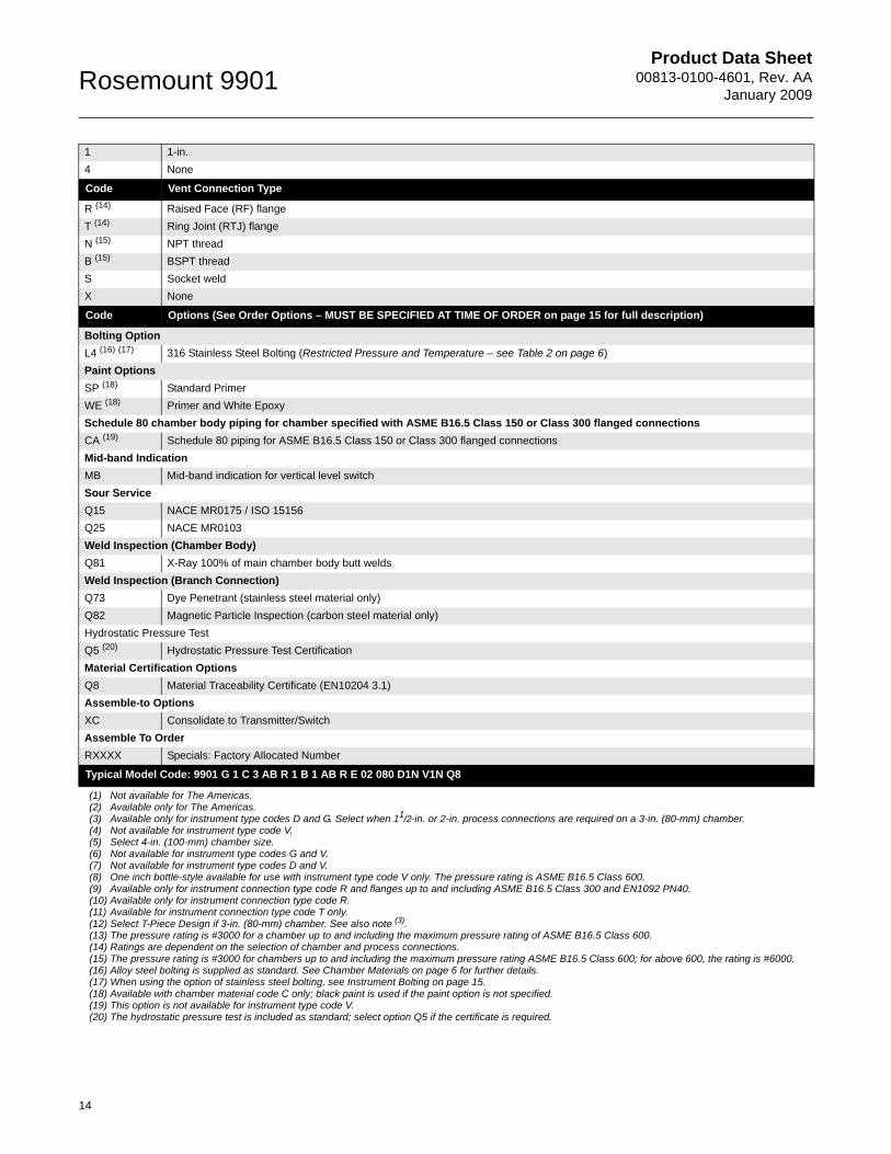
1 1-in.
4 None
Code Vent Connection Type
R (14) Raised Face (RF) flange
T (14) Ring Joint (RTJ) flange
N (15) NPT thread
B (15) BSPT thread
S Socket weld
X None
Code Options (See Order Options – MUST BE SPECIFIED AT TIME OF ORDER on page 15 for full description)
Bolting Option
L4 (16) (17) 316 Stainless Steel Bolting (Restricted Pressure and Temperature – see Table 2 on page 6)
Paint Options
SP (18) Standard Primer
WE (18) Primer and White Epoxy
Schedule 80 chamber body piping for chamber specified with ASME B16.5 Class 150 or Class 300 flanged connections
CA (19) Schedule 80 piping for ASME B16.5 Class 150 or Class 300 flanged connections
Mid-band Indication
MB Mid-band indication for vertical level switch
Sour Service
Q15 NACE MR0175 / ISO 15156
Q25 NACE MR0103
Weld Inspection (Chamber Body)
Q81 X-Ray 100% of main chamber body butt welds
Weld Inspection (Branch Connection)
Q73 Dye Penetrant (stainless steel material only)
Q82 Magnetic Particle Inspection (carbon steel material only)
Hydrostatic Pressure Test
Q5 (20) Hydrostatic Pressure Test Certification
Material Certification Options
Q8 Material Traceability Certificate (EN10204 3.1)
Assemble-to Options
XC Consolidate to Transmitter/Switch
Assemble To Order
RXXXX Specials: Factory Allocated Number
Typical Model Code: 9901 G 1 C 3 AB R 1 B 1 AB R E 02 080 D1N V1N Q8
(1) Not available for The Americas.(2) Available only for The Americas.(3) Available only for instrument type codes D and G. Select when 11/2-in. or 2-in. process connections are required on a 3-in. (80-mm) chamber.(4) Not available for instrument type code V.(5) Select 4-in. (100-mm) chamber size.(6) Not available for instrument type codes G and V.(7) Not available for instrument type codes D and V.(8) One inch bottle-style available for use with instrument type code V only. The pressure rating is ASME B16.5 Class 600.(9) Available only for instrument connection type code R and flanges up to and including ASME B16.5 Class 300 and EN1092 PN40.(10) Available only for instrument connection type code R.(11) Available for instrument connection type code T only.(12) Select T-Piece Design if 3-in. (80-mm) chamber. See also note (3).(13) The pressure rating is #3000 for a chamber up to and including the maximum pressure rating of ASME B16.5 Class 600.(14) Ratings are dependent on the selection of chamber and process connections.(15) The pressure rating is #3000 for chambers up to and including the maximum pressure rating ASME B16.5 Class 600; for above 600, the rating is #6000.(16) Alloy steel bolting is supplied as standard. See Chamber Materials on page 6 for further details.(17) When using the option of stainless steel bolting, see Instrument Bolting on page 15.(18) Available with chamber material code C only; black paint is used if the paint option is not specified.(19) This option is not available for instrument type code V.(20) The hydrostatic pressure test is included as standard; select option Q5 if the certificate is required.

Product Data Sheet00813-0100-4601, Rev. AAJanuary 2009
15
Rosemount 9901
ORDER OPTIONS – MUST BE SPECIFIED AT TIME OF ORDER
Instrument BoltingA range of alloy steel bolting is used as standard (see page 6 for details). However, stainless steel bolting is an available option for chamber ratings up to and including ASME B16.5 Class 600 and EN1092 PN100.
NOTE:When stainless steel bolting is used and the chamber ratings are below ASME B16.5 Class 600 and EN1092 PN63, the maximum chamber temperature is 752 °F (400 °C) and the maximum pressure ratings are detailedin Table 14.
When stainless steel bolting is used and the chamber ratings are ASME B16.5 Class 600, EN1092 PN63, or EN1092 PN100, the maximum chamber temperature is limited to 392 °F (200 °C.) and the maximum pressure ratings are detailed in Table 15.
Table 14. Maximum Pressure Ratings for Chambers rated below ASME B16.5 Class 600 or EN1092 PN63 – PSI and Bar
Table 15. Maximum Pressure Ratings for Chambers rated ASME B16.5 Class 600 or EN1092 PN63/PN100 – PSI and Bar
PaintThe standard is high quality, general purpose stoving black paint. White epoxy paint is an available option and consists of a primer, two undercoats of a two-pack high-build undercoat, and a final coat of a two-pack epoxy full gloss finish. The chamber can also be provided with just a primer for on-site painting.
Upon request, the 9901 can be painted to a customer specification.
Schedule 80 Piping for ASME B16.5 Class 150 or ASME B16.5 Class 300 Rated ChambersThe standard pipe schedule for these ratings is Schedule 40. An option is available to increase this to Schedule 80 except for the Vertical Level Float Switch, where the diameter of the float limits the chamber body to Schedule 40.
Mid-band IndicationThe standard switch point for a Vertical Level Float Switch (instrument type code V) is 2 in. (50 mm) below the center line of the top process flange, and is indicated on the chamber.
A mid-point switch point is also available halfway between the process connections. This option should be selected if a mid-band level switch is being installed.
Sour ServiceMaterials can be conditioned and tested for use in H2S environments with options for NACE MR0175/ISO 15156 (Materials for use in H2S-containing environments in oil and gas production) and MR0103 (Materials Resistant to Sulfide Stress Cracking in Corrosive Petroleum Refining Environments).
Chamber Rating(Max. Class 300/PN40)
Carbon Steel Chamber (With Stainless Steel Bolting) Stainless Steel Chamber (With Stainless Steel Bolting)
PSI (68 F) Bar (20 C) PSI (752 F) Bar (400 C) PSI (68 F) Bar (20 C) PSI (752 F) Bar (400 C)
ASME B16.5 Class 150 285 19.6 95 6.5 275 19 95 6.5
ASME B16.5 Class 300 740 51.1 505 34.7 720 49.6 425 29.4
EN1092 PN16 232 16 137 9.5 227 15.7 134 9.3
EN1092 PN25 362 25 214 14.8 356 24.6 211 14.6
EN1092 PN40 580 40 345 23.8 569 39.3 339 23.4
Chamber Rating(Max. Class 600/PN100)
Carbon Steel Chamber (With Stainless Steel Bolting) Stainless Steel Chamber (With Stainless Steel Bolting)
PSI (68 F) Bar (20 C) PSI (392 F) Bar (200 C) PSI (68 F) Bar (20 C) PSI (392 F) Bar (200 C)
ASME B16.5 Class 600 1480 102.1 1268 87.6 1440 99.3 1032 71.3
EN1092 PN63 913 63 761 52.5 899 62 645 44.5
EN1092 PN100 1450 100 1208 83.3 1427 98.4 1025 70.7
Product Data Sheet00813-0100-4601, Rev. AA
January 2009Rosemount 9901
16
Test and InspectionChambers can be subjected to rigorous testing and inspection. The following testing is available upon request:
• Weld InspectionX-Ray can be used to inspect welds on the chamber body. Inspection of the branch connection welds is available using Dye Penetrate Inspection (DPI) on stainless steel, and Magnetic Particle Inspection (MPI) is used for carbon steel welds.
• Hydrostatic Pressure Test
Hydrostatic pressure tests are performed as standard on all 9901's with certification available upon request.
• Material Certification
Material traceability certification conforming to EN 10204 3.1 is available, and Positive Material Identification (PMI) can also be ordered. PMI is a process to identify the composition of the material of the chamber and can be requested to support any material certificates that have been supplied. Requests for PMI should be made when making an enquiry.
• Documentation
The following documents are available:
• Outline dimensional drawings can be supplied for approval prior to construction• Weld procedures and welder qualifications• Quality control plans define the activities planned to deliver the product while meeting the quality
expectation of the customer
We can accommodate any request for inspections by a customer or third party organizations. This normally takes place prior to shipping.
ValvesValves are commonly mounted on the drain or vent connection to allow draining or venting of the chamber. It is common practice to also mount valves on the process connection to allow isolation of the chamber. Valves can be supplied with the 9901, and details are available upon request.

Product Data Sheet00813-0100-4601, Rev. AAJanuary 2009
17
Rosemount 9901

Product Data Sheet00813-0100-4601, Rev. AA
January 2009Rosemount 9901
18

Product Data Sheet00813-0100-4601, Rev. AAJanuary 2009
19
Rosemount 9901
Rosemount Level Solutions
Emerson provides a complete range of Rosemount products for level measurement applications.
Pressure – Level or Interface Measurement
Emerson has a complete line of Rosemount pressure transmitters and remote seals for measuring level or interfaces in liquid applications. Optimize performance with direct mount, Tuned Seal systems:
• Rosemount 3051S_L, 3051L, and 1151LT Liquid Level Transmitters
• Rosemount 1199 Remote Diaphragm Seals with direct mount or capillary connections
Vibrating Fork Switches – Point Level Detection
The Rosemount 2100 Series is developed for reliable point level detection of liquids and consists of:
• Rosemount 2110 Compact Vibrating Fork Liquid Level Switch
• Rosemount 2120 Full-featured Vibrating Fork Liquid Level Switch
Guided Wave Radar – Level and Interface Measurement
Multivariable, loop-powered Guided Wave Radar transmitters with a wide range of probe styles to fit different liquids and solids applications. The product line consists of:
• Rosemount 3300 Series – Versatile and easy-to-use transmitter with proven reliability
• Rosemount 5300 Series – Accurate, high performance transmitter with FOUNDATION™ fieldbus support
Non-contacting Radar – Level Measurement
The Rosemount non-contacting radar family consists of:
• Rosemount 5400 Series Transmitters – Loop-poweredtransmitter with a wide range of antennas, for liquid level measurement in most applications and process conditions
• Rosemount 5600 Series Transmitters – Transmitters with ultra-high sensitivity for measurement of level in liquids and solids, even for the most challenging applications
Non-contacting Ultrasonic – Level Measurement
The Rosemount 3100 Series ultrasonic level transmitters provide continuous non-contacting level measurement of liquids. The range consisits of:
• Rosemount 3101 for simple continuous level measurement
• Rosemount 3102 for continuous measurement with two integral relays for local control functionality
• Rosemount 3105 Intrinsically safe certified version for hazardous areas
The Emerson logo is a trademark and service mark of Emerson Electric Co.Rosemount and the Rosemount logotype are registered trademarks of Rosemount Inc.PlantWeb is a registered trademark of one of the Emerson Process Management group of companies.HART is a registered trademark of the HART Communication Foundation.DeltaV is a registered trademark of Emerson Process Management group of companies.All other marks are the property of their respective owners.
Standard Terms and Conditions of Sale can be found at www.rosemount.com\terms_of_sale
© 2009 Rosemount, Inc.
Emerson Process Management Rosemount Inc.8200 Market BoulevardChanhassen, MN 55317 USAT (U.S.) 1-800-999-9307T (International) (952) 906-8888F (952) 949-7001www.rosemount.com
Emerson Process ManagementBleigistrasse 23P.O. Box 1046CH 6341 BaarSwitzerlandT +41 (0) 41 768 6111F +41 (0) 41 768 6300
Emerson Process ManagementAsia Pacific Pte Ltd1 Pandan CrescentSingapore 128461T +65 6777 8211F +65 6777 0947Service Support Hotline: +65 6770 8711Email: [email protected]
Emerson FZEP.O. Box 17033Jebel Ali Free ZoneDubai UAET +971 4 883 5235F +971 4 883 5312
Product Data Sheet00813-0100-4601, Rev. AA
January 2009Rosemount 9901
00813-0100-4601 Rev AA 01/09