rostec ad8 analog to digital converter ad8 analog to digital converter.pdf · ad8 analog to digital...
TRANSCRIPT
AD8 Analog to Digital Converter
1
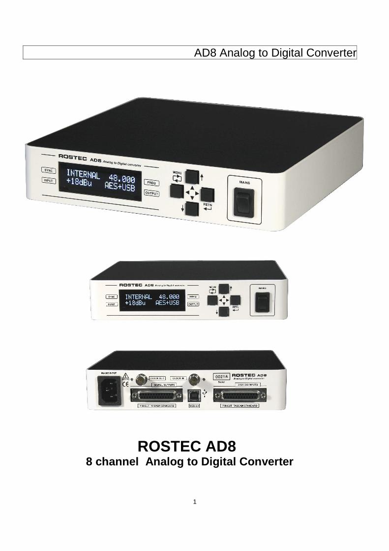
ROSTEC AD8 8 channel Analog to Digital Converter
AD8 Analog to Digital Converter
2
Table of contents General Front page……………………………………………………..…........ 1 Contents………………………………………………………........…. 2 Features ………………………………………………………............ 3 General description …………………......…………………………… 3 Analog Inputs.................................................……………………… 4 USB input and outputs....…………….....…………………….....…… 4 Digital outputs (AES)...................................................................... 5 Clock sync input and output.......................................................... 5 Power Supply................................................................................ 5 Operational description Front panel quick guide...................……....................................... 6 Back panel quick guide.……......................................................... 9 Back panel connectors pin-out............….…………...................... 10 Mechanical and electrical specifications …………...…..….… 11 Technical section Classical Distortion Analysis........................................................ 12 FFT distortion analysis................................................................ 13 Crosstalk..................................................................................... 14 Hum and noise..............…………………...................................... 15
AD8 Analog to Digital Converter
3
Features
• 8 channels of Analog to Digital conversion to the DAW via USB, and/or directly to the AES outputs.
• 8 channels of Digital from the DAW routed via USB directly to the AES outputs.
• 192 kHz 24 bit high-end latest generation converters.
• Dynamic range 115 dB (higher internally, but limited by op-amp noise).
• USB 2.0 class compliant bit perfect interface. • Transformer balanced 110 ohm AES outputs. • Industry leading Low Latency performance. • Easy interfacing via standard D-sub 25 and
USB B connectors. • Internal low jitter Grade 2 word clock
generator. • Exceptional high immunity against jitter and
digital noise from computer work stations. • Word clock Input has an automatic "sweet
spot" detector, providing auto-slicing and signal clean-up.
• Word clock input accept from 0.2 Volts to 10 Volts.
• Electronically balanced analog input buffers. • Analog JFET and BJT cascode technology
with the same characteristics as vacuum tubes for exquisite sonic performance.
• Analog level signal switching by hermetically sealed relays with gold contact.
• Analog and digital true balanced architecture throughout the unit.
• Linear low noise analog power supply. • Internal magnetic and electrical screening. • Digital Inputs and outputs are ESD protected
to 23 kV, IEC 61000-4-2 and 15 A surge, IEC 61000-4-5.
• Sturdy steel metal casing, half size 19” 1U height.
• Affordable price. High value for money.
General description With its true class A and carefully designed analog circuitry, Rostec AD8 represents a sound quality that is far above what you will find in the standard digital interfaces flooding the market today. AD8 features 8 channels of streaming audio inputs to the DAW, and 8 channels of streaming audio from the DAW to the AES outputs. AD8 is constructed with a throughout balanced architecture, meaning that audio signals, analog as well as digital, are routed internally as balanced signals, not using ground to transfer audio signals at all. This architecture keeps the audio path free from non-linear distortion from currents in the ground mesh and free from “non musical” signals from external electrical fields, power supply noise and crosstalk from other channels. All analog signal switching is performed by hermetically sealed relays with gold contacts. There are no digital analog switching, no digital level adjustments, and there are no digital processing, except from the AD conversion process. The analog circuit features a soft clipper with a threshold just a little bit above digital clipping. This means that you can ride the converter hard and continuous at the clipping level from your DAW without getting the ugly sound break-up so well known from standard digital interfaces and sound cards. At the digital clipping level, the analog circuit still has an extra headroom of 12 dB above the digital clipping. Also, the power supply is pure analog for a quiet and noise-free environment. We want none of that severe digital noise pollution from switch mode power supplies, thank you! This highly sophisticated design gives AD8 a large dynamic range, huge headroom and ultra low noise and distortion, and the result is a beautiful relaxed, open, warm and natural sound, with an impressive amount of details and an astonishing depth and perspective. Gone is the ugly, cold, flat and lifeless sound you get from the typical standard digital interfaces or sound cards. This is classical analog quality at its very best, and digital technology used wisely.
AD8 Analog to Digital Converter
4
Analog Inputs The AD8 has eight analog audio inputs on the standard 25 pin D-sub connector at the back panel. The connector follows the TASCAM DB-25 industrial pin-out standard. The inputs are electronically balanced, but can be used in unbalanced mode, by connecting the negative terminal to ground. The input impedance is 10 kohm, and the max input is +30 dBu. The analog inputs have two sensitivity settings, which can be selected at the front:
1. +18 dBu at 0 dBFS, which is the official EBU standard, used by Broadcast Corporations all over the EU.
2. +10 dBu at 0 dBFS, which is optimal for use with old (vintage) equipment. Older equipment has a 0 VU level which corresponds to +4 dBu electric level. Setting the sensitivity level to +10 dBu leaves 6 dB of extra headroom for peaks above 0 VU. This setting provides an operating level that brings out the best of most vintage equipment.
As the line inputs have a +30 dBu clipping limit and communicates with the DAW at +18 dBu/+10 dBu at Digital Full Scale, input clipping cannot be experienced under normal operational circumstances. USB output and input The USB connector is a type B , the most physical robust of all USB connectors. The USB connection features a bit-perfect transmission protocol, which is USB 2.0 class compliant and directly compatible with USB 2.0, 3.0, 3.1, 3.2 and USB-C. AD8 supports Core-Audio on MAC OS X systems. When plugged in, the 8 analog input channels and the 8 AES output channels show up on the MIDI-setup panel and are immediately available as system resources for any DAW. Windows is not supported. The Windows operating system is NOT recommended to handle professional streaming audio equipment via USB.
The AD8 has three USB modes:
1. USB. The unit converts 8 channels of analog audio into 8 channels of digital audio, with output on the USB. The digital output (AES) output is dormant.
2. USB+AES. The unit converts 8 channels of analog audio into 8 channels of digital audio, with output on the USB, and at the same time, the 8 channels of digital audio are output on the digital output connector (AES).
3. USB>AES. The unit converts 8 channels of analog audio into 8 channels of digital audio, with output on the USB, and at the same time, it returns 8 separate channels of digital audio from the DAW to the digital output connector (AES)
Running the AD8 in any of the USB modes present some restrictions that must be observed.
1. The DAW controls the sampling frequency. Unlike in AES mode, the sampling frequency cannot be changed manually with the arrow buttons.
2. There is no Sample Rate Conversion available. The USB format will not allow that. Any Sample Rate Conversion must be performed within the Work Station or the DAW.
3. If more than one USB unit is connected to the Work Station, all units must be synchronized to the same Word Clock. Else the system will drop or repeat audio samples, which can be heard as stuttering or clicking in the sound.
When running in any USB mode, the actual sampling rate frequency is shown in the display at the upper right corner. When any USB mode is selected, but no connection to the workstation is made, the sampling frequency will be displayed as NONE, and the unit will be in pause mode, i.e. there will be no clock output and no AES output.
AD8 Analog to Digital Converter
5
Digital outputs (AES) The AD8 has four digital outputs on the standard 25 pin D-sub connector at the back panel. The connector follows the YAMAHA DB-25 industrial pin-out standard. The digital outputs are transformer balanced, impedance 110 ohm, 6.6 Volts no load and 3.3 Volts into 110 ohm. The output format follow the AES3 standard, which means the four AES outputs give eight output channels in total (AES3 is a stereo format). In AES mode, the output sampling frequency is selected by the arrow buttons on the front. In the USB+AES and USB>AES modes, the sampling frequency is controlled by the Work Station or the DAW. The actual sampling frequency is always shown at the right upper corner of the display. If any USB mode is selected, but no USB connection is present, the sampling frequency reads NONE, and the unit will be in pause mode, i.e. no clock output and AES outputs. Clock sync input and output The AD8 has input and output for clock synchronization on the standard BNC connectors at the back. The input is 1.5 kohm ( i.e. not terminated ) and the output clock is 75 ohm 5 Volts, TTL compatible. The clock input features a high-speed comparator with hysteresis and a "sweet spot" detector, which performs an accurate auto-slicing of the input. This means that the circuit automatically chooses the most useful part of the input signal, thus being able to clean-up and reconstruct a ringing and noisy input clock into a perfect output clock used to internally synchronize the unit. The unit is built with sync safety in mind. It always uses the internal low jitter oscillator as the master clock for all internal digital signals, and it always uses the master clock oscillator to generate the output clock. When it locks to an incoming clock, it continues to use the internal oscillator as the master clock, but it gently adjust the oscillator frequency to match the frequency of the incoming signal, creating a phase lock between clock input and clock output. When the incoming clock signal is lost or discontinued, the master clock oscillator gently glides back to its internal reference, while continuing to generate sync signals without disruption. Thus, there are never gabs or disturbances of any kind when the clock sync is lost and re-established.
The unit works as an excellent clock reference generator for a studio setup. In AES mode, the output clock frequency is manually controlled at the front panel with the arrow buttons. In any USB mode, the output clock frequency is controlled by the Work Station or the DAW. The internal clock accuracy is typically +/-2 ppm, and the pulse shape of the long-haul output clock buffer is close to theoretically perfect, with impressive jitter and noise specifications, steep rise time and no ringing, even with long cables. Power Supply The power supply is pure analog, with an oversized toroidal transformer and low noise linear regulators. This configuration creates an electromagnetic quiet environment, free from the usual radiation pollution from a switch-mode power supply. A switch mode power supply generates strong repetitive electromagnetic pulses that travel through air and sharp current pulses that travel through the ground system. When this pollution hit the analog circuitry, it disrupt the smooth operation of the circuitry by pressing the amplifiers into slew-rate-mode momentarily But what is slew-rate-mode? It is when an amplifier is presented with a signal, that moves faster that the amplifiers maximum speed capability. It then tries to “slew” as fast as it can, to cope with the signal. When the amplifier is in this mode, it cannot process any further information, it is in fact blocked from reproducing incoming audio signals. This happens in short durations, when the pulses from a switch mode power supply hit the circuit. The result is that 60.000 a second the analog circuit looses, in small intervals, the ability to reproduce audio, and this is in fact the main reason why audio products with switch mode power supplies sound harsh, flat and lifeless, with a degraded ability to process details and depth in the audio. DA8 maintains a clean electromagnetic environment in the box, and the reward is a natural, pleasant, open and detailed sound.
AD8 Analog to Digital Converter
6
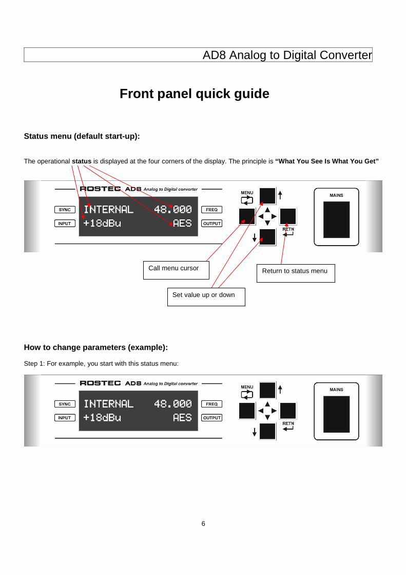
Front panel quick guide Status menu (default start-up): The operational status is displayed at the four corners of the display. The principle is “What You See Is What You Get”
How to change parameters (example): Step 1: For example, you start with this status menu:
Call menu cursor
Set value up or down
Return to status menu
AD8 Analog to Digital Converter
7
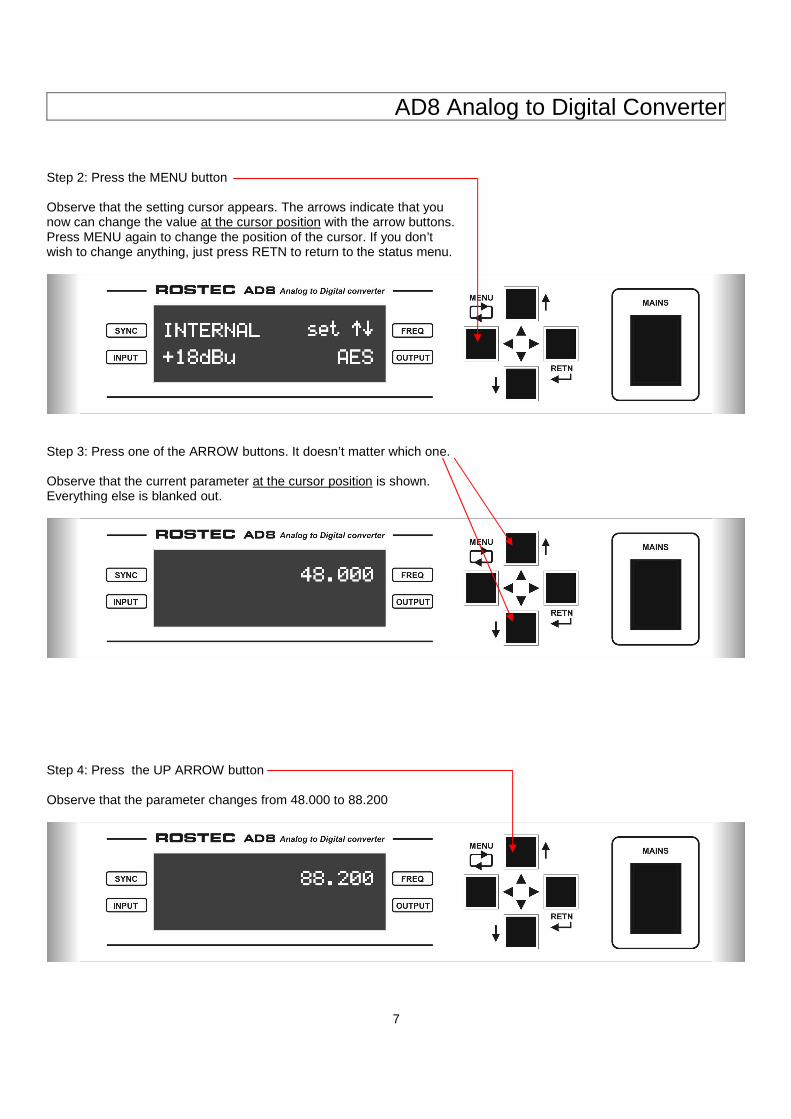
Step 2: Press the MENU button Observe that the setting cursor appears. The arrows indicate that you now can change the value at the cursor position with the arrow buttons. Press MENU again to change the position of the cursor. If you don’t wish to change anything, just press RETN to return to the status menu.
Step 3: Press one of the ARROW buttons. It doesn’t matter which one. Observe that the current parameter at the cursor position is shown. Everything else is blanked out.
Step 4: Press the UP ARROW button Observe that the parameter changes from 48.000 to 88.200
AD8 Analog to Digital Converter
8
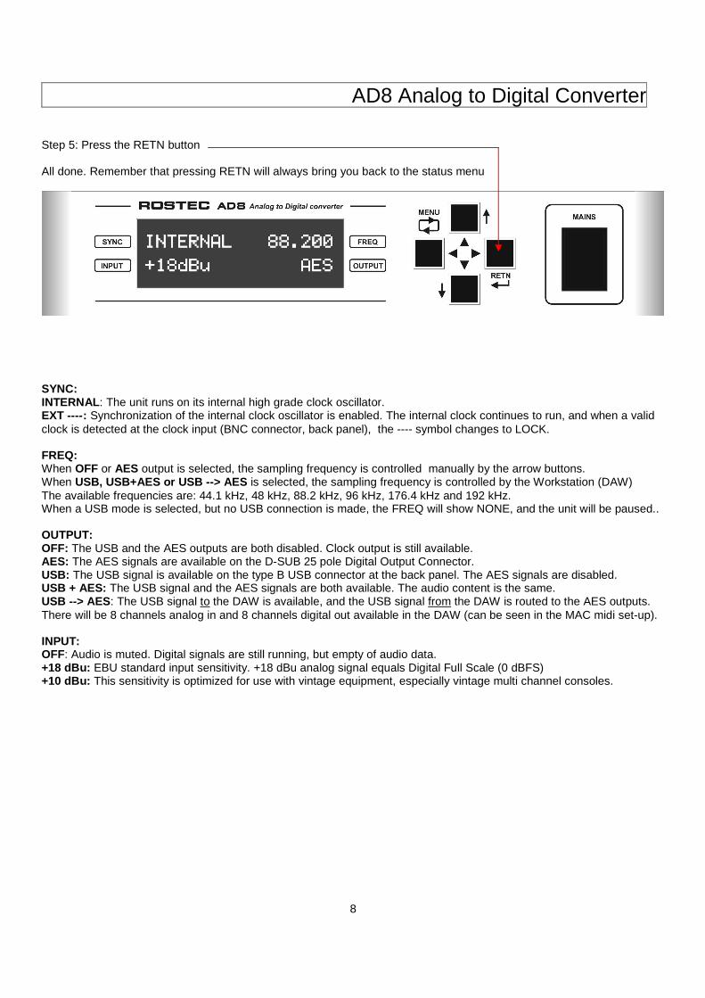
Step 5: Press the RETN button All done. Remember that pressing RETN will always bring you back to the status menu
SYNC: INTERNAL : The unit runs on its internal high grade clock oscillator. EXT ---- : Synchronization of the internal clock oscillator is enabled. The internal clock continues to run, and when a valid clock is detected at the clock input (BNC connector, back panel), the ---- symbol changes to LOCK. FREQ: When OFF or AES output is selected, the sampling frequency is controlled manually by the arrow buttons. When USB, USB+AES or USB --> AES is selected, the sampling frequency is controlled by the Workstation (DAW) The available frequencies are: 44.1 kHz, 48 kHz, 88.2 kHz, 96 kHz, 176.4 kHz and 192 kHz. When a USB mode is selected, but no USB connection is made, the FREQ will show NONE, and the unit will be paused.. OUTPUT: OFF: The USB and the AES outputs are both disabled. Clock output is still available. AES: The AES signals are available on the D-SUB 25 pole Digital Output Connector. USB: The USB signal is available on the type B USB connector at the back panel. The AES signals are disabled. USB + AES: The USB signal and the AES signals are both available. The audio content is the same. USB --> AES : The USB signal to the DAW is available, and the USB signal from the DAW is routed to the AES outputs. There will be 8 channels analog in and 8 channels digital out available in the DAW (can be seen in the MAC midi set-up). INPUT: OFF: Audio is muted. Digital signals are still running, but empty of audio data. +18 dBu: EBU standard input sensitivity. +18 dBu analog signal equals Digital Full Scale (0 dBFS) +10 dBu: This sensitivity is optimized for use with vintage equipment, especially vintage multi channel consoles.
AD8 Analog to Digital Converter
9
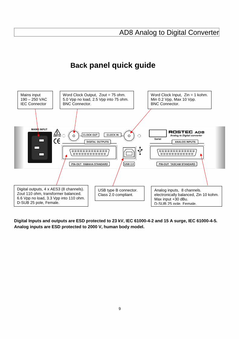
Back panel quick guide
Digital Inputs and outputs are ESD protected to 23 kV, IEC 61000-4-2 and 15 A surge, IEC 61000-4-5. Analog inputs are ESD protected to 2000 V, human bo dy model.
Word Clock Output, Zout = 75 ohm. 5.0 Vpp no load, 2.5 Vpp into 75 ohm. BNC Connector.
Word Clock Input, Zin = 1 kohm. Min 0.2 Vpp, Max 10 Vpp. BNC Connector.
Mains input 190 – 250 VAC IEC Connector
Digital outputs, 4 x AES3 (8 channels). Zout 110 ohm, transformer balanced. 6.6 Vpp no load, 3.3 Vpp into 110 ohm. D-SUB 25 pole, Female.
Analog inputs, 8 channels. electronically balanced, Zin 10 kohm. Max input +30 dBu. D-SUB 25 pole, Female.
USB type B connector. Class 2.0 compliant.
AD8 Analog to Digital Converter
10
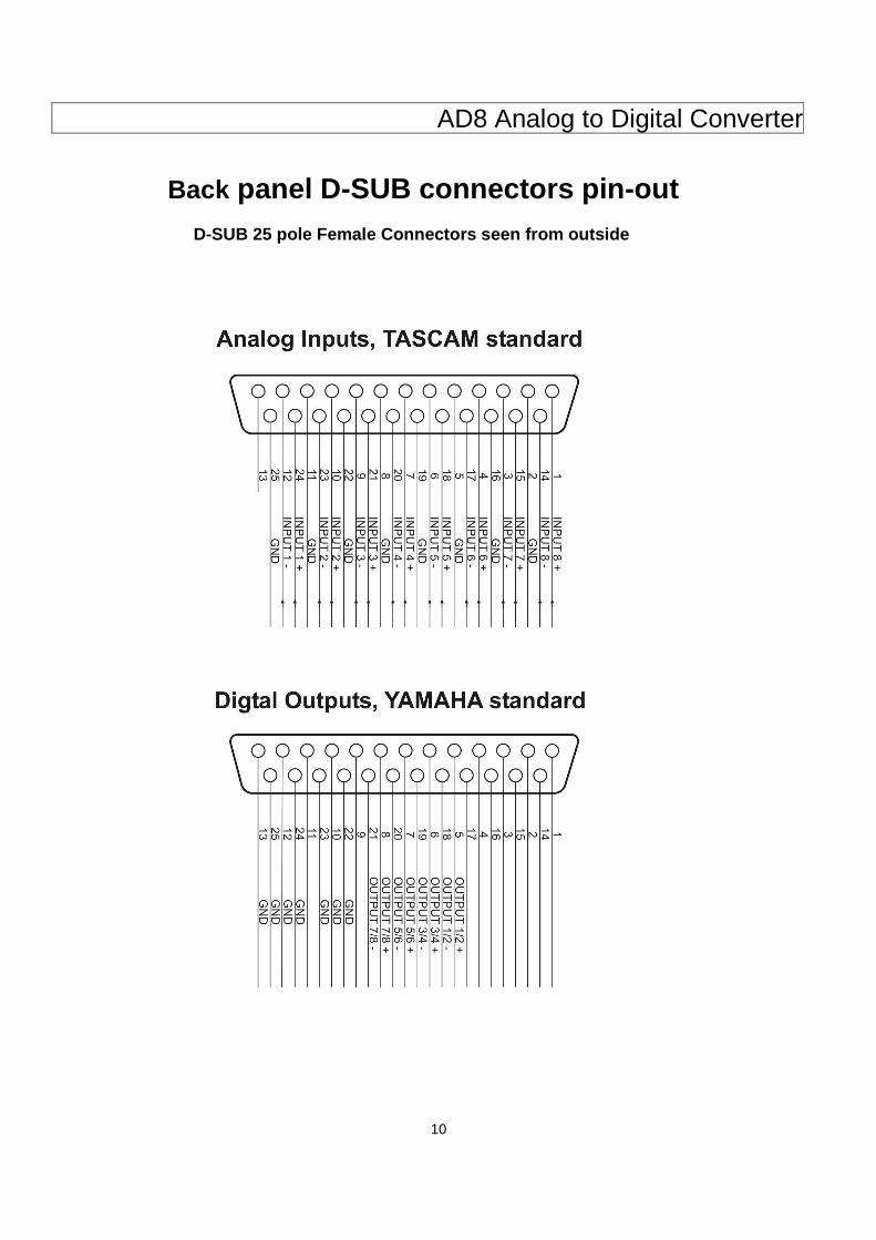
Back panel D-SUB connectors pin-out D-SUB 25 pole Female Connectors seen from outside
AD8 Analog to Digital Converter
11
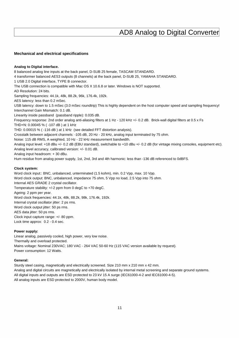
Mechanical and electrical specifications Analog to Digital interface. 8 balanced analog line inputs at the back panel, D-SUB 25 female, TASCAM STANDARD. 4 transformer balanced AES3 outputs (8 channels) at the back panel, D-SUB 25, YAMAHA STANDARD. 1 USB 2.0 Digital interface, TYPE B connector. The USB connection is compatible with Mac OS X 10.6.8 or later. Windows is NOT supported. AD Resolution: 24 bits. Sampling frequencies: 44.1k, 48k, 88.2k, 96k, 176.4k, 192k. AES latency: less than 0.2 mSec. USB latency: down to 1.5 mSec (3.0 mSec roundtrip) This is highly dependent on the host computer speed and sampling frequency! Interchannel Gain Mismatch: 0.1 dB. Linearity inside passband (passband ripple): 0.035 dB. Frequency response: 2nd order analog anti-aliasing filters at 1 Hz - 120 kHz +/- 0.2 dB. Brick-wall digital filters at 0.5 x Fs THD+N: 0.00045 % ( -107 dB ) at 1 kHz THD: 0.00015 % ( -116 dB ) at 1 kHz (see detailed FFT distortion analysis). Crosstalk between adjacent channels: -105 dB, 20 Hz - 20 kHz, analog input terminated by 75 ohm. Noise: 115 dB RMS, A weighted, 10 Hz - 22 kHz measurement bandwidth. Analog input level: +18 dBu +/- 0.2 dB (EBU standard), switchable to +10 dBu +/- 0.2 dB (for vintage mixing consoles, equipment etc). Analog level accuracy, calibrated version: +/- 0.01 dB. Analog input headroom: + 30 dBu. Hum residue from analog power supply, 1st, 2nd, 3rd and 4th harmonic: less than -136 dB referenced to 0dBFS. Clock system: Word clock input:: BNC, unbalanced, unterminated (1.5 kohm), min. 0.2 Vpp, max. 10 Vpp. Word clock output: BNC, unbalanced, impedance 75 ohm, 5 Vpp no load, 2.5 Vpp into 75 ohm. Internal AES GRADE 2 crystal oscillator. Temperature stability: +/-2 ppm from 0 degC to +70 degC. Ageing: 2 ppm per year. Word clock frequencies: 44.1k, 48k, 88.2k, 98k, 176.4k, 192k. Internal crystal oscillator jitter: 2 ps rms. Word clock output jitter: 50 ps rms. AES data jitter: 50 ps rms. Clock input capture range: +/- 80 ppm. Lock time approx: 0.2 - 0.4 sec. Power supply: Linear analog, passively cooled, high power, very low noise. Thermally and overload protected. Mains voltage: Nominal 230VAC; 180 VAC - 264 VAC 50-60 Hz (115 VAC version available by request). Power consumption: 12 Watts. General: Sturdy steel casing, magnetically and electrically screened. Size 210 mm x 210 mm x 42 mm. Analog and digital circuits are magnetically and electrically isolated by internal metal screening and separate ground systems. All digital inputs and outputs are ESD protected to 23 kV 15 A surge (IEC61000-4-2 and IEC61000-4-5). All analog inputs are ESD protected to 2000V, human body model.
AD8 Analog to Digital Converter
12
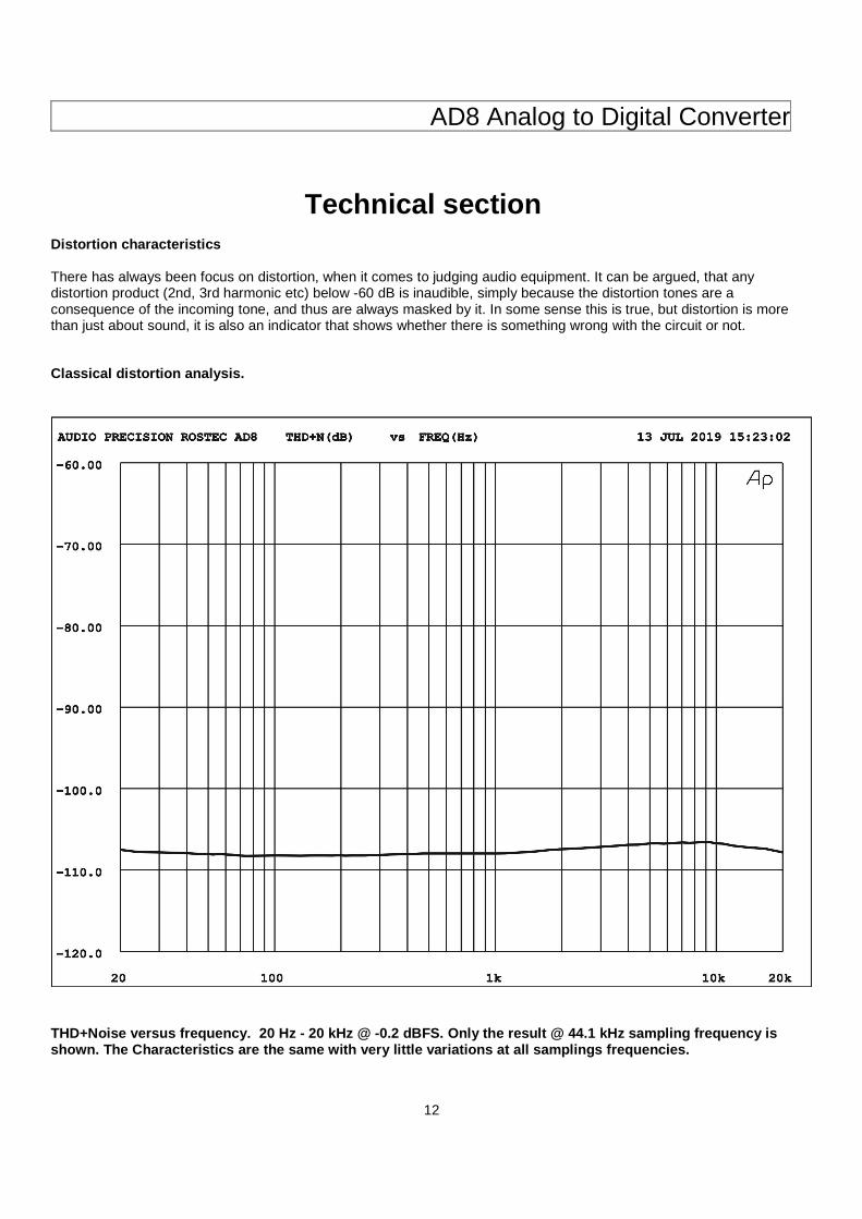
Technical section Distortion characteristics There has always been focus on distortion, when it comes to judging audio equipment. It can be argued, that any distortion product (2nd, 3rd harmonic etc) below -60 dB is inaudible, simply because the distortion tones are a consequence of the incoming tone, and thus are always masked by it. In some sense this is true, but distortion is more than just about sound, it is also an indicator that shows whether there is something wrong with the circuit or not. Classical distortion analysis.
THD+Noise versus frequency. 20 Hz - 20 kHz @ -0.2 dBFS. Only the result @ 44.1 kHz sampling frequency is shown. The Characteristics are the same with very l ittle variations at all samplings frequencies.
AD8 Analog to Digital Converter
13
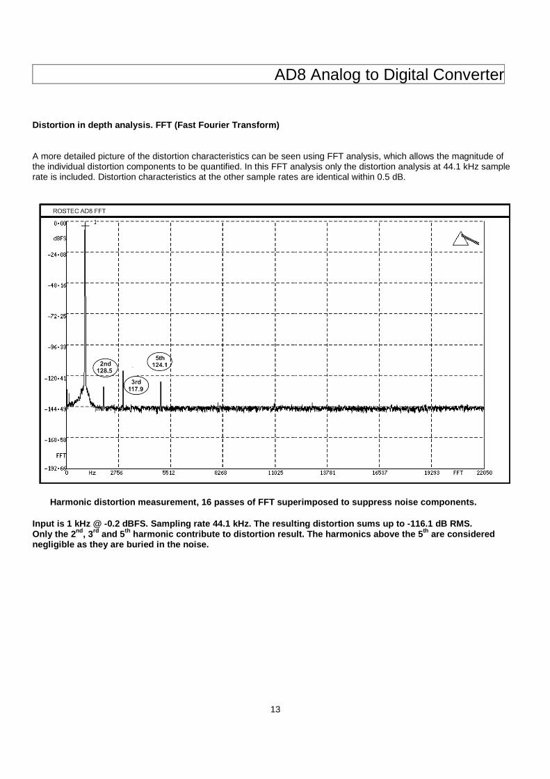
Distortion in depth analysis. FFT (Fast Fourier Transform) A more detailed picture of the distortion characteristics can be seen using FFT analysis, which allows the magnitude of the individual distortion components to be quantified. In this FFT analysis only the distortion analysis at 44.1 kHz sample rate is included. Distortion characteristics at the other sample rates are identical within 0.5 dB.
Harmonic distortion measurement, 16 passes o f FFT superimposed to suppress noise components. Input is 1 kHz @ -0.2 dBFS. Sampling rate 44.1 kHz. The resulting distortion sums up to -116.1 dB RMS. Only the 2 nd, 3rd and 5 th harmonic contribute to distortion result. The harm onics above the 5 th are considered negligible as they are buried in the noise.
AD8 Analog to Digital Converter
14
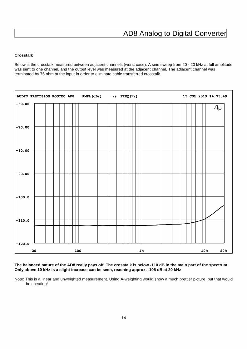
Crosstalk Below is the crosstalk measured between adjacent channels (worst case). A sine sweep from 20 - 20 kHz at full amplitude was sent to one channel, and the output level was measured at the adjacent channel. The adjacent channel was terminated by 75 ohm at the input in order to eliminate cable transferred crosstalk.
The balanced nature of the AD8 really pays off. The crosstalk is below -110 dB in the main part of the spectrum. Only above 10 kHz is a slight increase can be seen, reaching approx. -105 dB at 20 kHz Note: This is a linear and unweighted measurement. Using A-weighting would show a much prettier picture, but that would be cheating!
AD8 Analog to Digital Converter
15
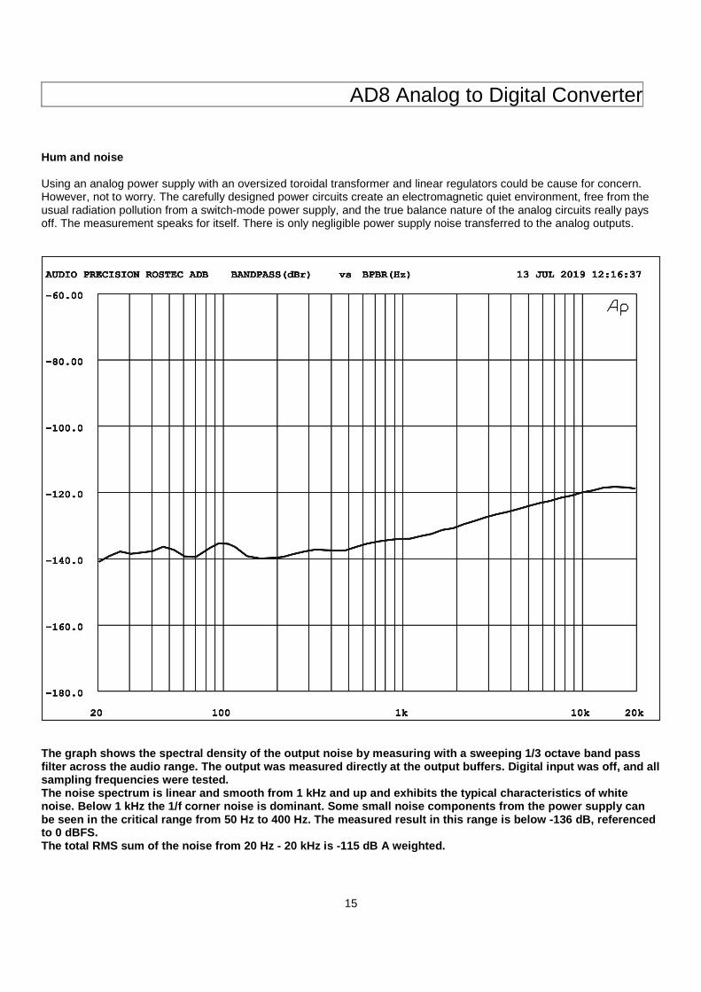
Hum and noise Using an analog power supply with an oversized toroidal transformer and linear regulators could be cause for concern. However, not to worry. The carefully designed power circuits create an electromagnetic quiet environment, free from the usual radiation pollution from a switch-mode power supply, and the true balance nature of the analog circuits really pays off. The measurement speaks for itself. There is only negligible power supply noise transferred to the analog outputs.
The graph shows the spectral density of the output noise by measuring with a sweeping 1/3 octave band pass filter across the audio range. The output was measu red directly at the output buffers. Digital input w as off, and all sampling frequencies were tested. The noise spectrum is linear and smooth from 1 kHz and up and exhibits the typical characteristics of white noise. Below 1 kHz the 1/f corner noise is dominant . Some small noise components from the power supply can be seen in the critical range from 50 Hz to 400 Hz. The measured result in this range is below -136 dB , referenced to 0 dBFS. The total RMS sum of the noise from 20 Hz - 20 kHz is -115 dB A weighted.