rotary actuator series cra1 - smc · cra1 mounting shaft style size f rotation with built-in...
TRANSCRIPT

∗∗
Series VariationsFluid Air Hydraulic oil Page
Size
Sta
nd
ard
Mad
e to
Ord
er
Rotationangle
Shaft style
Cushion
Variations
Mounting bracket
Material of main part
Shaft style
Operating temp.
Patterns
Both sides angle adjustableOne side angle adjustable, One side with cushion
-X10-X11
Fluorine rubber as seal material -X16
-X6
Option
90°100°180°190°
Single shaftDouble shaftSingle shaft with four chamfersDouble shaft keyDouble shaft with four chamfers
Without air cushionWith air cushion
With auto switchAngle adjustable styleWith solenoid valveClean specificationCopper free (standard)Built-in one-touch fittingsFlange
Floot
Stainless steel
100oC at maximum
Shaft end shapeRotation rangePort location
Single shaftSingle shaft with four chamfersDouble shaft keyDouble shaft with four chamfersSingle round shaftDouble shaft (Round, With four chamfers)
Double round shaft
SWXYZ
11-
F
L
SXYZTJK
30 50 63 80 100 50 63 80 100
1.3-2
1.3-28to
1.3-29
1.3-46to
Series CRA1Rack Pinion Style/Size: 30, 50, 63, 80, 100
Rotary Actuator
Models with cushion or with solenoid valve available.(Only sizes ≥50 are available.)
Angle adjustement is possible.Size 30··················· Fine angle adjuster is
standard equipment.Size 50 or larger·····Angle adjustable styleAuto switch is mountable.Adjustment of switch location is easy withrail mounting.
1.3-1
CRA1
CRB1
CRBU
CRQ
MRQ
MSQ
MSUB
CRA1 SERIES-1 2/16/99 9:41 AM Page 1

∗∗
CRA1 B W 30 90
CRA1 B S 50 90
Size 30
Sizes 50 to 100
Mounting styleBL
B L∗F
BasicFoot
MountingBasicFoot
Flange
90°180° Rod end shape
Rotation angle
Double shaft
90180
∗Refer to the tables below for parts number.
Shaft styleSWS
td.
Opt
ion
Single shaft
PneumaticAir-hydro
—H
Styles
506380
100
Size
90°180°100°190°
90180100190
Std
.O
ptio
n
Rotation angle
Air CushionWithout air cushion
With air cushion—C
30
50
63
80
100
Foot bracket
CRA1L30-Y-1
CRA1L50-Y-1
CRA1L63-Y-1
CRA1L80-Y-1
CRA1L100-Y-1
Mounting screws included in foot bracket
M5 X 0.8 X 25
M8 X 1.25 X 35
M10 X 1.5 X 40
M12 X 1.75 X 50
M12 X 1.75 X 50
Notes) The part numbers shown above include mounting screw.As ordering foot bracket, write "1 piece" for the bracket for one rotary actuator.
Foot Brackets Part No.
Rotary Actuator
Series CRA1Rack Pinion Style/Size: 30, 50, 63, 80, 100
How to Order
Double shaftSingle shaft with
four chamfersDouble shaft keyDouble shaft with
four chamfers
Size
X
Z
Y
1.3-2
CRA1 SERIES-1 2/16/99 9:41 AM Page 2

∗∗
1.3-3
Allowable Kinetic Energy/Safe Range of Rotation Time
Weight/Standard
Model
Allowable kinetic energy
Allowable kinetic energy (J)Cushion angle
Safe range of rotation time
Rotation time (s/90°)
0.2 to 1
0.2 to 2
0.2 to 3
0.2 to 4
0.2 to 5
Without cushion
0.01
0.05
0.12
0.16
0.54
0.98
1.5
2.0
2.9
35°
35°
35°
35°
CRA1lW30
CRA1ll50
CRA1ll63
CRA1ll80
CRA1ll100
Model
CRA1BW30
CRA1BW50
CRA1BW63
CRA1BW80
CRA1BW100
CRA1BW30
CRA1BW50
CRA1BW63
CRA1BW80
CRA1BW100
90°
0.3
1.5
2.5
4.3
8.5
180°
0.4
1.7
3
5
9.5
Foot bracket
0.1
0.3
0.5
0.9
1.2
Flange bracket
0.5
0.9
1.5
2
Standard weight Additional weight
(kg)
Weight/With Auto Switches and Solenoid Valves
Size
30
50
63
80
100
Additional weight
With 2 auto switches
0.1
0.2
0.4
0.6
0.9
With solenoid valve∗
0.2
0.2
0.2
0.2
(kg)
∗ Weight of the solenoid valve is not included. Refer to p.1.3-17 concerning weight of the solenoid valve.
SpecificationsStyle
Size
Fluid
Max. operating pressure
Min. operating pressure
Cushion
Output (1) (Nm)
Allowable surge pressure
Backlash
Ambient and fluidtemperature
Tolerance in rotating angle
Pneumatic Air-hydro
63
Air (Non-lube)
1MPa
0.1MPa
0° to 60°C (No freezing)
80 100 50 63
Hydraulic oil
+4° 0
1.5MPa
80 1005030
None
9.31.9 17 32 74 9.3 17 32 74
NoneWith or without air cushion
(2)
Note 1) Output under the operating pressure of 0.5MPa. Refer to p.1.0-28 for further information.Note 2) Since CRA1l30 has a stopper installed, there is no backlash produced under pressure.
With cushion (1)
Note 1) Allowable kinetic energy of the bumpers equipped modelThe maximum absorbed energy under proper adjustment of the cushion needle.
Within 1°
OrderMade
Precaution
P.1.3-29 to 1.3-46
Be sure to read before handling.Refer to p.0-20 and 0-21 for Safety Instructions and common precautions on the products mentioned in this catalog, and refer to p.1.0-2 to 1.0-4 for precautions on every series.
Rotary ActuatorRack Pinion Style Series CRA1
CRA1
CRB1
CRBU
CRQ
MRQ
MSQ
MSUB
CRA1 SERIES-1 3/3/99 10:42 PM Page 3
∗∗
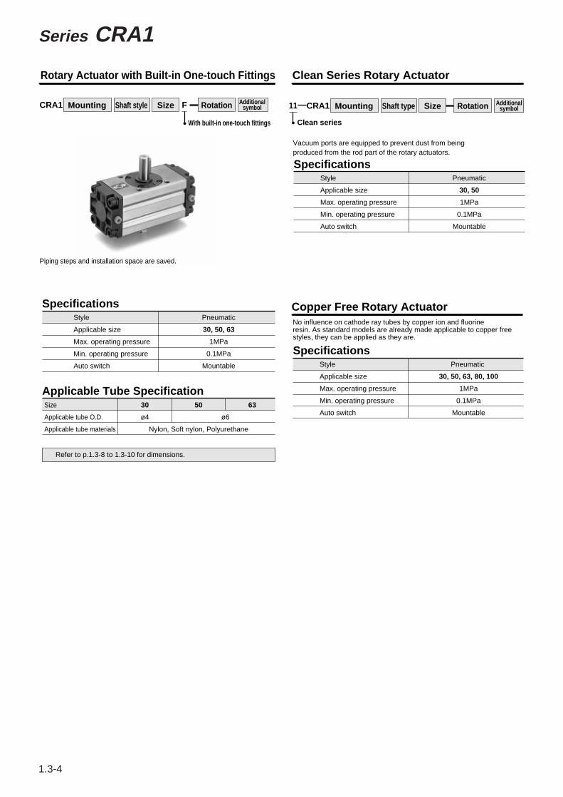
CRA1 Mounting Shaft style Size RotationF
With built-in one-touch fittings
Vacuum ports are equipped to prevent dust from beingproduced from the rod part of the rotary actuators.
Copper Free Rotary ActuatorNo influence on cathode ray tubes by copper ion and fluorineresin. As standard models are already made applicable to copper freestyles, they can be applied as they are.
Rotary Actuator with Built-in One-touch Fittings Clean Series Rotary Actuator
Piping steps and installation space are saved.
Specifications
Applicable Tube Specification
Style
Applicable size
Max. operating pressure
Min. operating pressure
Auto switch
Size
Applicable tube O.D.
Applicable tube materials
30 50
Nylon, Soft nylon, Polyurethane
63
ø4 ø6
Pneumatic
30, 50, 63
1MPa
0.1MPa
Mountable
Refer to p.1.3-8 to 1.3-10 for dimensions.
CRA1 Size Additionalsymbol11
Clean series
SpecificationsStyle
Applicable size
Max. operating pressure
Min. operating pressure
Auto switch
Pneumatic
30, 50
1MPa
0.1MPa
Mountable
SpecificationsStyle
Applicable size
Max. operating pressure
Min. operating pressure
Auto switch
Pneumatic
30, 50, 63, 80, 100
1MPa
0.1MPa
Mountable
Additionalsymbol Mounting Shaft type Rotation
1.3-4
Series CRA1
CRA1 SERIES-1 2/16/99 9:41 AM Page 4

∗∗
1.3-5
Stopper screw A: For end adjustment in clockwise directionStopper screw B: For end adjustment in counter clockwise
How to Set The Rotation TimeEven if the torque that is generated by the rotary actuator is small, the parts could become damaged depending on the inertia of the load. Therefore, the rotation time should be determined by calculating the load's inertial moment and kinetic energy. Refer to p.1.0-33 and 1.0-34 for details on how to set the rotation time.
Allowable load on the shaftRefer to the model selecting order step 3 for rotary actuators on p.1.0-14concerning allowable loads on the shafts of series CRA1.
Rotation range of key
groo
ve90
°
Rotation range of key
groo
ve18
0°
Rotation range of key groove 190° +4°0
0Rotation range of key groove 180°+4°
Rotation range of key gr
oove
100°
+4°
Rotation range ofke
ygr
oove
90°
+4°
Size: 30 Size: 50 to 100
If air pressure is applied from the A side of the direction indication label, the shaft rotates clockwise. If air pressure is applied from the B side, the shaft rotates counterclockwise.
Rotation Range of Key Grooves
direction.
CRA1
CRB1
CRBU
CRQ
MRQ
MSQ
MSUB
Rotary ActuatorRack Pinion Style Series CRA1
CRA1 SERIES-1 2/16/99 9:41 AM Page 5

∗∗∗
No.
q
w
e
r
t
y
u
i
o
!0
!1
Body
Cover (Right)
Cover (Left)
Piston
Shaft
Rack
Stopper
Stopper screw
Slider
Bearing retainer
Tube gasket
Description Material
Aluminum alloy
Aluminum alloy
Aluminum alloy
Aluminum alloy
Chromium-molybdenum steel
Carbon steel
Chromium-molybdenum steel
Chromium-molybdenum steel
Resin
Zink alloy (1)
NBR
Note No.
!2
!3
!4
!5
!6
!7
!8
!9
@0
@1
@2
@3
Piston packing
O ring
BearingHexagon socket head capscrew spring washerHexagon socket head capflange screwCross-recessed countersunkhead screw
Hexagon nut
Spring pin
Parallel key
Parallel key
Connecting screwCross-recessed roundhead screw
Description Material
NBR
NBR
Carbon steel
Chromium-molybdenum steel
Chromium-molybdenum steel
Steel wire
Steel wire
Steel wire
Carbon steel
Carbon steel
Carbon steel
Steel wire
Note
Component Parts Component Parts
Note 1) Size 50 to 100: Aluminum alloy (Black alumite)
Construction
Without air cushionSize: 30
Without air cushionSize: 50 to 100
Black zinc chromated
Zinc chromated
Black dyed
Black dyed
Zinc chromated
Black zinc chromated
Hard anodized
Black anodized
Black anodized
Chromated
Nitrided
Black dyed
Black painted
1.3-6
Series CRA1
CRA1 SERIES-1 2/16/99 9:41 AM Page 6

∗∗
No.
@4
@5
@6
@7
@8
@9
#00
#1
#2
#3
Auto switch mounting rail
Auto switch
Plastic magnet
Cross-recessed head cap screw
Hexagon nut
Needle valve
Lock nut
Cushion packing
O ring
Cross-recessed head cap screw
Description Material
Aluminum alloy
Magnetic substance
Steel wire
Steel wire
Steel wire
Steel wire
NBR
NBR
Steel wire
Note
Nickel plated
Nickel plated
Nickel plated
Nickel plated
Nickel plated
Size
P294010-20
P294010-21
P294020-20A
P294030-20A
P294040-20
P294050-20A
P294020-20A
P294030-20A
P294040-20
P294050-20A
P294010-20
P294010-21
P294020-20A
P294030-20A
P294040-20
P294050-20A
P294020-23A
P294030-23A
P294040-23
P294050-23A
Standard With air cushion
Replacement parts
With auto switch Air-hydro
Component Parts Replacement Parts (Corresponding parts shown below are set.)
CRA1lW30-90
CRA1lW30-180
CRA1ll50
CRA1ll63
CRA1ll80
CRA1ll100o, !1, !2, and !9 are set.
Note) When ordering spare parts, write "1 piece" for 1 set of the parts for one actuator.
Size: 50 to 100
With auto switchSize: 30
With air cushion
Corresponding parts
1.3-7
CRA1
CRB1
CRBU
CRQ
MRQ
MSQ
MSUB
Rotary ActuatorRack Pinion Style Series CRA1
CRA1 SERIES-1 2/16/99 9:42 AM Page 7

∗∗
Series CRA1
Size 30/Standard: CRA1BW, Foot Style: CRA1LW
l 28 8-M5 X 0.8 Depth 6(Four positions on the back)
9.2
2-M5 X 0.8
A port B port9
5.5 5.5
84(103)
ø16
ø8g6
3 0-0.025
0 -0.2
29
5 l 40
l 6
l28
ø16
225
143
4-ø6Mounting hole
40
A port B port
124 (143)
144 (163)
3.2
24
69
∗ The dimensions above show pressurization to B port.∗ ( ) are the dimensions for rotation of 180°
StandardCRA1BW30 ········ SCRA130, According to #2 (#2+#16+#18), auto switch (#16) is eliminated.Foot styleCRA1LW30 ········· SCRA130, According to #6 (#6+#16+#18), auto switch (#16) is eliminated.
Foot style/CRA1LW30
Standard/CRA1BW30
7565
28
1.3-8
CRA1 SERIES-1 2/16/99 9:42 AM Page 8

∗∗
Rotary ActuatorRack Pinion Style
1.3-9
CRA1BS50
CRA1BS63
CRA1BS80
CRA1BS100
Models ModelsA
1/8
1/8
1/4
3/8
62
76
92
112
B
48
60
72
85
C
46
57
70
85
D(g6)
D(g6)
DD(h9)
15
17
20
25
25
30
35
40
F
2.5
2.5
3
4
H
36
41
50
60
J K
5
5
5
5
S U
98
117
142
172
W
17
19.5
22.5
28
BA
17
20
23.5
25
BB
8.5
10
12
12.5
15
17
20
25
G
11
13
15
19
M
20
22
25
30
N
15
17
20
25
UU
118
139
167
202
L
14
16
19
24
CA∗
8.5
10
12
12.5
CB∗
13
14
18
18
Port sizeRc(PT)
M8 X 1.25Depth 8
144(177)
163(201.5)
186(230)
245(311)
M10 X 1.5Depth 12
M12 X 1.75Depth 13
M12 X 1.75Depth 14
25
30
40
45
Key dimensionslb
5 0-0.030
0-0.030
0-0.030
0-0.036
6
6
8
CRA1BW50
CRA1BW63
CRA1BW80
CRA1BW100
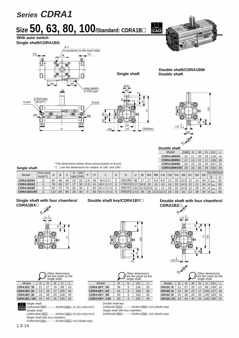
Size 50, 63, 80, 100/Standard: CRA1Bl
Single shaft with fourchamfers/CRA1BX
Double shaft key/CRA1BY Double shaft with fourchamfers/CRA1BZ
Single shaftCRA1BS Size ......SCRA1 Size , According to #1 (#1+#16+#17), auto switch (#16) is eliminated.Double shaftCRA1BW Size .....SCRA1 Size , According to #2 (#2+#16+#17), auto switch (#16) is eliminated.Single shaft with four chamfersCRA1BX Size ......SCRA1 Size , 13 (Shaft only)
Models G11131519
H27293844
N15172025
U89
105130156
L14161924
CRA1BX50CRA1BX63CRA1BX80CRA1BX100
Models H36415060
K5555
UU134158192232
l
25304045
CRA1BY50CRA1BY63CRA1BY80CRA1BY100
Models H27293844
M20222530
N15172025
UU109127155186
L14161924
CRA1BZ50CRA1BZ63CRA1BZ80CRA1BZ100
Size: 50 to 100Single shaft style/CRA1BS
∗The dimensions above show pressurization to B port.
∗( ) are the dimensions for rotations of 180° and 190°.
Note) Other dimensions are the same as the single shaft.
G11131519
Double shaft keyCRA1BY Size ......SCRA1 Size , #14 (Shaft only)Double shaft with four chamfersCRA1BZ Size .....SCRA1 Size , #15 (Shaft only)
Double shaft style/CRA1BWDouble shaft
Note) Other dimensions are the same as the single shaft.
Single shaft
Note) Other dimensions are the same as the single shaft.
Note) Other dimensions are the same as the single shaft.
CRA1
CRB1
CRBU
CRQ
MRQ
MSQ
MSUB
Series CRA1
CRA1 SERIES-1 2/16/99 9:42 AM Page 9

∗∗
Series CRA1
Models LA
62
76
92
112
F
4
5
5
5
H
39
45
55
60
114
136
165
190
9
11.5
13.5
13.5
13
15
18
18
90
105
130
150
50
59
76
92
110
130
160
180
81
101
119
133
MM U FD FT FX FY ZX ZY
9
11
13
13
44
55
67
87
41 108 4.5200(233)
235(273.5)
274(318)
333(399)
224(257)
263(301.5)
316(360)
375(441)
LB LC LD LE LF LH LT Models
CRA1Fll50
CRA1Fll63
CRA1Fll80
CRA1Fll100
M6 X1.0Depth12
M6 X1.0Depth12
M8 X1.25Depth16
M10 X1.5Depth20
∗Dimensions above show pressurization to B port.∗( ) are the dimensions for rotation of 180o and 190o. Other dimensions are the same as standard.
Size 50, 63, 80, 100/Foot Style: CRA1Ll, Flange Style: CRA1FlFoot style/CRA1Ll Flange style
Single shaft/CRA1FS
Flange styleDouble shaft/CRA1FW
Flange styleSingle shaft with four chamfers/CRA1FX
Flange styleDouble shaft key/CRA1FY
Flange styleDouble shaft with four chamfers/CRA1FZ
CRA1Lll50
CRA1Lll63
CRA1Lll80
CRA1Lll100
Models H39455560
N15172025
U114136165190
UU134158190220
CRA1FWl50CRA1FWl63CRA1FWl80CRA1FWl100
Models H30334344
N15172025
U105124153174
H39455560
U114136165190
UU150177215250
CRA1FXl50CRA1FXl63CRA1FXl80CRA1FXl100
ModelsCRA1FYl50CRA1FYl63CRA1FYl80CRA1FYl100
Models H30334344
N15172025
U105124153174
UU125146178204
CRA1FZl50CRA1FZl63CRA1FZl80CRA1FZl100
Other dimensions are the same as the single shaft.
Other dimensions are the same as the single shaft.
Other dimensions are the same as the single shaft.
Other dimensions are the same as the single shaft.
Single shaft foot styleCRA1L Size ··············SCRA1 Size , According to #5 (#5+#16+#17), auto switch (#16) is eliminated.Single shaft flange styleCRA1F Size ··············SCRA1 Size , According to #9 (#9+#16+#17), auto switch (#16) is eliminated.Double shaft flange styleCRA1FW Size ···········SCRA1 Size , According to #10 (#10#16+#17), auto switch (#16) is eliminated.
Single shaft with four chamfersCRA1FX Size ············SCRA1 Size , #13 (Shaft only)Double shaft keyCRA1FY Size ·············SCRA1 Size , #14 (Shaft only)Double shaft with four chamfersCRA1FZ Size ·············SCRA1 Size , #15 (Shaft only)
48
58
73.5
127
154
189.5
5
6
6
1.3-10
CRA1 SERIES-1 2/16/99 9:43 AM Page 10

∗∗∗
C B W30
C
D
D
RA1
RA1 B W S50 90 A53
90Size 30
Size 50 to 100
SA72
BL
BasicFoot
90°180°
Rotation angle90180
BL∗
F
MountingBasicFoot
Flange
Built-in magnet
506380
100
Size
Shaft stylesSW
Single shaftDouble shaftS
td.
Opt
ion
PneumaticAir-hydro
—H
Style
CushionWithout cushion
With cushion—C
Auto switch
S—
12
∗ Refer to the table below for part numbers of applicable auto switch.
Note) Max. no. auto switches mountable is two.
Rotation angle90180100190
90°180°100°190°
Std
.
Mounting
Rotary Actuator with Auto Switch
Series CDRA1Rack Pinion Style/Size: 30, 50, 63, 80, 100
How to Order
Optio
n
Style
Ree
d sw
itch
Solid
sta
te s
witc
h
Special function
Diagnostic indicator (2 color)
Diagnostic indicator (2 color)
Water resistant (2 color)(2)
Timer
Electrical entry
Grommet Yes
No
No
No
Yes
Yes
Yes
Yes
Grommet
Grommet
Grommet
Connector
ConnectorGrommet
Connector
Indi
cato
r
Wiring (Output)
3 wire(Equivalent to NPN)
2 wire
2 wire
2 wire
2 wire
3wire(NPN)
3wire(PNP)
3wire(PNP)
3wire(NPN)
3wire(NPN)
4wire(NPN)
Load voltage Auto switch part No.
DC ACSize 30 Size 50 to 100
In-linePerpendicular In-line0.5(—)
3(L)
5(Z)
—(N)
Lead wire length
Applicable load
5V
5V,12V
12V
5V,12V
5V,12V
24V
24V
A76H IC
IC
IC
IC
IC
IC
IC
IC
200V
100V
≤ 100V
≤ 24V
100V,200V
100V,200V
100V,200V
12V
5V,12V
12V
12V
5V,12V
A72
A73
A80
A73C
A80C
A79W
F7NV
F7PV
F7BV
J79C
A72H
A73H
A80H
F79
F7P
J79
F7PW
F79W
J79W F7BA(2)
F7NT
A56
A53
A54
A67
A64
A59W
J51
F59
F5P
J59
F5PW
F59W
J59W
PLC
PLC
RelayPLC
RelayPLC
RelayPLC
RelayPLC
Note 1) Symbols for wire lengths 0.5m····· (—) Ex.) A80C3m········· L Ex.) A80CL
5m·········· Z Ex.) A80CZ — ·········N Ex.) A80CN
Auto switches marked with " " in the table are made to order specification.Note 2) This rotary actuator is not a improved product in water proof.• Consult SMC when using F7BA∗ and F5BA∗.
Auto Switch Specifications/Refer to p.2.11-1 for further specifications of auto switch single unit.
––––
––––
Diagnostic output (2 color)
No.of auto switches mounted
F5BA(2)
F5NT
F59F
(1)
(m)
Single shaft withfour chamfers
Double shaft withfour chamfers
Double shaft key
X
Y
Z
Refer to p.1.3-2 for part numbers of foot bracket.
1.3-11
CRA1
CRB1
CRBU
CRQ
MRQ
MSQ
MSUB
CRA1 SERIES-1 2/16/99 9:43 AM Page 11

∗∗∗
1.3-12
Model A (mm)
9 (19)
9 (26)
11 (30)
15 (37)
27 (60)
Operating angle θm
95°65°60°45°35°
Angle of hysteresis (1)
CDRA1lW30-90
CDRA1ll50-90
CDRA1ll63-90
CDRA1ll80-90
CDRA1ll100-90
∗ The dimensions inside "( )" are for 180°. ∗∗ Up to 2 auto switches can be mounted per actuator.The dimensions in the table are the values that represent the most sensitive positions of the auto switches. Thus, they are not the dimensions that represent the mounting position at the time of shipment.
∗ Consult SMC concerning the angles for the auto switches other than the models D-A73 and D-A53.
Operating angle θ m: Converts the operating range (Lm) of the auto switch into the rotation angle (1)Angle of hysteresis: The hysteresis of the auto switch is converted to degrees.
Model Part No.
P294010-24
P294020-24
CDRA1lW30
CDRA1ll50 to100
Note 1) The above part numbers include 2 pieces of mounting screws and 2 pieces of nuts.
Note 2) To order a set for 1 unit, the ordering quantity should be "1".
Sets of mounting screws for auto switch (Round head Phillips screw, Hexagon nut)
Caution
In the diagram below, switch B is ON. When pressure is applied from A, the piston moves to B, causing the shaft to rotate clockwise. At this time, magnet B goes out of the movement range of switch B, causing switch B to turn OFF. Furthermore, the piston moves to the right, causing magnet A to enter the movement range of switch A. As a result, switch A turns ON.
Size: 30CDRA1lW30
CDRA1lW30
Size: 50 to 100CDRA1ll50 to 100
CDRA1ll50 to 100
Rotation Range of Key Grooves/Switch Mounting Positions Operation Principles
Proper Mounting Positions for Auto Switches
Rotation range ofke
y groov
e90
°
Rotation range of key
groov
e 180
°
Rotation ra nge of k ey groove 190°
Rota tion range of key groove 180°+4°
0°
+4°0°
Be sure to read before handling.Refer to p.2.11-2 to 2.11-4 before handling auto switches.
20°20°10°7°5°
Rotation range of
key gr
oove
90°+4
o
Rotation range of
key gr
oove
100°
+4o
0
0
Series CDRA1
CRA1 SERIES-1 2/16/99 9:43 AM Page 12

Series CDRA1Rotary Actuator with Auto SwitchRack Pinion Style
∗∗
Size 30/Standard: CDRA1BW, Foot Style: CDRA1LW
StandardCDRA1BW30 ········ SCRA130, #2 (#2+#16+#18)Foot styleCDRA1LW30 ········· SCRA130, #6 (#6+#16+#18)
Foot style/CDRA1LW30
With auto switchStandard/CDRA1BW30
∗ The dimensions above show pressurization to B port.∗ ( ) are the dimensions for rotation of 180°
1.3-13
CRA1
CRB1
CRBU
CRQ
MRQ
MSQ
MSUB
CRA1 SERIES-1 2/16/99 9:44 AM Page 13
∗∗∗
Series CDRA1
Size 50, 63, 80, 100/Standard: CDRA1BlWith auto switchSingle shaft/CDRA1BS
CA
8-J(4 positions on the back side)
CAlB
SA SA
Auto switchD-A53 typeW
2-Port sizeRC(PT)A port
BB BB
BA BA
S
B port
øDD
øD
b
CB(Max)lAlC
U
HlF
K
SE
SD
Single shaftDouble shaft/CDRA1BWDouble shaft
UU
N M
lG 0
-0.2
0-0.1
H
øL
øL
lG lG
lG
N H
U
øL
H
UU
HlK
N
U
N M
SB
SC
øL
øD
CDRA1BS50CDRA1BS63CDRA1BS80CDRA1BS100
627692
112
48607285
46577085
15172025
25303540
2.52.534
36415060
5555
98117142172
1719.522.528
1720
23.525
8.51012
12.5
8.51012
12.5
13141818
33333333
13.514.515.516
12121212
14212939
34343434
25304045
156(189)175(213.5)199(243)259(325)
M8 X1.25 X 8M10 X 1.5 X 12
M12 X 1.75 X 13M12 X 1.75 X 14
ModelPort sizeRc(PT)
A B C F H J K S U W BA BB CA CB SA SB SC SD SEDD(h9)
D(g6)
Key dimensionslb
18
18
14
38
5-0-0.0306
0-0.030
6 -0-0.030
8 0-0.036
CDRA1BW50CDRA1BW63CDRA1BW80CDRA1BW100
Model
20222530
15172025
118139167202
14161924
15172025
M N UU LD(g6)
Single shaft∗The dimensions below show pressurization to B port.∗( ) are the dimensions for rotation of 180° and 190°.
GDouble shaft
Single shaft with four chamfers/CDRA1BXl
Double shaft key/CDRA1BYl Double shaft with four chamfers/CDRA1BZl
Model H27293844
N15172025
U89
105130156
L14161924
CDRA1BXl50CDRA1BXl63CDRA1BXl80CDRA1BXl100
Model H36415060
K5555
UU134158192232
l
25304045
CDRA1BYl50CDRA1BYl63CDRA1BYl80CDRA1BYl100
Model H27293844
M20222530
N15172025
U89
105130156
UU109127155186
L14161924
CDRA1BZl50CDRA1BZl63CDRA1BZl80CDRA1BZl100
G11131519
G11131519
Other dimensions are the same as the single shaft.
Size
Size
Size
Size
Size Size
Size Size
Size
Size
Single shaftCDRA1BS ············SCRA1 , #1 (#1+#16+#17)Double shaft CDRA1BW ··········SCRA1 , #2 (#2+#16+#17)Single shaft with four chamfersCDRA1BX ············SCRA1 , #13 (Shaft only)
Double shaft keyCDRA1BY ············SCRA1 , #14 (Shaft only)Single shaft with four chamfersCDRA1BZ ············SCRA1 , #13 (Shaft only)
UU
Other dimensions are the same as the single shaft.
Other dimensions are the same as the single shaft.
0-0.2
0-0.1
11131519
1.3-14
CRA1 SERIES-1 3/11/99 2:02 PM Page 14

∗∗
Series CDRA1
LA
62
76
92
112
LB
9
11
13
13
LC
44
55
67
87
LD212
(245)
247(285.5)
287(331)
347(413)
LE236
(269)
275(313.5)
329(373)
389(455)
LH
108
127
154
189.5
LF
41
48
58
73.5
LT
4.5
5
6
6
F
4
5
5
5
H
39
45
55
60
MM U
114
136
165
190
FD
9
11.5
13.5
13.5
FT
13
15
18
18
FX
90
105
130
150
FY
50
59
76
92
ZX
110
130
160
180
ZY
81
101
119
133
CDRA1Lll50
CDRA1Lll63
CDRA1Lll80
CDRA1Lll100
CDRA1Fll50
CDRA1Fll63
CDRA1Fll80
CDRA1Fll100
CDRA1FWl50CDRA1FWl63CDRA1FWl80CDRA1FWl100
H39455560
N15172025
U114136165190
UU134158190220
U105124153174
CDRA1FXl50CDRA1FXl63CDRA1FXl80CDRA1FXl100
H30334344
N15172025
CDRA1FYl50CDRA1FYl63CDRA1FYl80CDRA1FYl100
H39455560
U114136165190
UU150177215250
CDRA1FZl50CDRA1FZl63CDRA1FZl80CDRA1FZl100
H30334344
N15172025
U105124153174
UU125146178204
Size 50, 63, 80, 100/Foot Style: CDRA1L, Flange Style: CDRA1LW
Model ModelM6 X 1.0Depth 12M6 X 1.0Depth 12
M8 X 1.25Depth 16M10 X 1.5Depth 20
ModelModelModelModel
Other dimensions are the same as the single shaft.
Other dimensions are the same as the single shaft.
Other dimensions are the same as the single shaft.
Other dimensions are the same as the single shaft.
∗Dimensions above show pressurization to B port.∗( ) are the dimensions for rotation of 180° and 190°. Other dimensions are the same as standard.
Size
Size
Size
Size
Size Size
Size Size
Size
Size SizeSize
foot styleCDRA1L ··········SCRA1 , #5 (#5+#16+#17)Double shaft CDRA1F ········· SCRA1 , #6 (#6+#16+#17)Single shaft with four chamfersCDRA1W ······· SCRA1 , #10 ( #10+#16+#17)
Single shaft with four chamfersCDRA1FX ············SCRA1 , #13 (Shaft only)Double shaft keyCDRA1FY ············SCRA1 , #14 (Shaft only)Double shaft with four chamfersCDRA1FZ ············SCRA1 , #15 (Shaft only)
1.3-15
CRA1
CRB1
CRBU
CRQ
MRQ
MSQ
MSUB
Flange styleDouble shaft/CDRA1FW
Flange styleSingle shaft with fourchamfers/CDRA1FX
Flange styleDouble shaft key/CDRA1FY
Flange styleDouble shaft withfour chamfers/CDRA1FZ
Foot style/CDRA1L l Flange styleSingle shaft/CRA1FS
Rotary Actuator with Auto SwitchRack Pinion Style
CRA1 SERIES-1 2/16/99 9:45 AM Page 15

∗∗∗
1.3-16
CVRA1
CDVRA1
Rated voltage12345679
100V AC 50/60Hz200V AC 50/60Hz
110 to 120V AC, 50/60Hz220V AC, 50/60Hz
24V DC12V DC
240V AC, 50/60HzOther voltages
Electrical entryGHETDL
LNLOM
MNMO
Grommet (Lead wire:300mm)Grommet (Lead wire:600mm)
Grommet terminalConduit terminalDIN connector
L plugconnector
M plugconnector
With lead wireWithout lead wireWithout connector
Solenoid valveconfiguration
12345
Single solenoidDouble solenoidClosed centerExhaust centerPressure center
Light/surge voltage suppressor—Z∗S∗
—With light/surge suppressorWith surge suppressor
MountingBL
BasicFoot
Note) No flange type "F" is available.
Shaft stylesSW
Single shaftDouble shaft
Styles—U
StandardAngle adjustable
506380100
Size Cushion—C∗
Without cushionWith cushion
Rotation angle
Standard
Option
90180100190
90°180°100°190°
∗Except for angle adjustable type "U".
Auto switch∗ Refer to the table below
for part numbers ofapplicable auto switch.
No. of auto switches mounted
S—
12
Without auto switch
With auto switch
B S 50 90 1 1 G
B S 50 90 1 1 G SA53
Magnet installed
With solenoid valve
Manual override—BC
Non-locking style (Std.)Locking B styleLocking C style
With lead wireWithout lead wireWithout connector
Style Special function
Diagnostic indicator (2 color)
Diagnostic indicator (2 color)
Water resistant (2 color)
Timer
Diagnostic output (2 color)
Applicable loadElectrical entry
Indi
cato
r
Wiring(Output) DC AC
Auto switchpart No.
3(L)
5(Z)
Load voltage Lead wire length∗ (m)
Ree
d sw
itch
Sol
id s
tate
sw
itch
Grommet
Grommet
Yes
No
Yes
3 wire (Equiv. to NPN)
2 wire 24V
24V
24V
2 wire
2 wire
3 wire (NPN)3 wire (PNP)
4 wire (NPN)
3 wire (NPN)
3 wire (NPN)
3 wire (PNP)
5V
12V
5V, 12V
5V, 12V
5V, 12V
A56
A53
A54
A67
A64
A59W
F59
F5P
J51
J59
F5PW
F59W
J59W
F5BA
F5NT
F59F
PPPPPPPPPPPPP
P
PPPPPPPPPPPPPPP
PP
pppppppppp
IC
IC
IC
IC
IC
IC
PLC
Relay, PLC
Relay, PLC
Relay, PLC
PLC100V, 200V
100V, 200V
100V, 200V
∗Symbols for lead wire length 0.5m······ — Ex.) A533m········· L Ex.) A53L5m········· Z Ex.) A53Z
Auto Switch Specifications/ Refer to p.2.11-1 for further specifications of auto switch single unit.
12V
How to Order
——
——
——
——
————————
——
——
——
——
——
—— ——
——
——
——
——
——
—— ––
––––––
––––
∗Auto switches without contact point marked with "O" are made to order specification.P
∗Light attached type (Z) is not available for grommet type. Surge voltage suppressor attached style is available only for grommet style.
Yes
Series CVRA1Rack Pinion Style/Size: 50, 63, 80, 100
Rotary Actuator with Solenoid Valve
0.5(—)
X
Y
Z
Single shaft with four chamfers
Double shaft keyDouble shaft with four chamfers
CRA1 SERIES-1 2/16/99 9:45 AM Page 16

∗∗
1.3-17
CRA1
CRB1
CRBU
CRQ
MRQ
MSQ
MSUB
Rotary Actuator with Solenoid V alveRack Pinion Style Series CVRA1
Fluid
Proof pressure
Max. operating pressure
Min. operating pressure
Ambient and fluid temperature
Lubrication
Mounting
Air
1.35MPa
0.9MPa
0.15MPa
0OC to 50OC (No condensation)
Not required
Basic, Foot style
Part No. for solenoid valve
Electrical entry
Allowable voltage change
Coil insulation
Power consumption
VF3l20-llll-20-X14
Grommet, Grommet terminal Conduit ternimal, DIN connector
L plug connector, M plug connector
100, 200V(50/60Hz)
24V
-15% to +10% of the rated voltage
Equivalent to B class (130°C)
1.8W
5.6VA(50Hz), 5.0VA(60Hz)
3.4VA(50Hz), 2.3VA(60Hz)
Coil rated voltage
Apparent current
AC
DC
AC
DC
How to calculate weightWeight = Basic weight∗ + Add'l weight + No. of positions/solenoids∗Refer to p.1.3-3 for basic weight.
Weight
Specifications
Model
CVRA1ll 50 to 100
Add'lweight
0.2 0.2 0.3 0.4 0.4
No. of positions/solenoids
2 positionsingle
(kg)
2 positiondouble
3 positionclosed center
3 positionexhaust center
0.4
3 positionpressure center
Inrush
Holding
Rat
ed v
olta
ge
100Vor
less
100Vor
more
AC
DC
AC
DC
Note) Light is not available on grommet type.
Light/Surge suppresser
Manual override
Electrical wiring
Instant energizing time
How to adjust rotating speed
The DIN type terminal and the terminal pin (withlight and surge voltage suppressoer) are connectedinternally as shown below. Therefore, connectthem the respective power supply terminals.
Terminal No.DIN connectorTerminal block
1++
2--
To operate the double solenoid type by applyingan instantaneous current, ensure that the currentis applied for at least 0.1 second.
Rotation directionWhen current is applied SOL1, the shaftrotates clockwise.
How to adjust the rotation speed:Turn the needle valve of the throttle valveclockwise to reduce the exhaust flow volume,thus slowing the rotation speed.
Throttle valve A regulates the clockwiserotation speed of the shaft and throttle valve Bregulates the counterclockwise speed to theshaft.
Rotation rage of key grooves/Solenoid valve mounting positions
Rotation range of key gr
oove
Rotation range of key groov
e
Rotation range of key gro
ove
Rotation range of key gr
oove
PrecautionBe sure to read before handling.Refer to p.0-20 and 0-21 for Safety Instructions and common precautions on the products mentioned in this catalog, and refer to p.1.0-2 to 1.0-4 for precautions on every series.
Non-locking push style is standard.
Terminal
Terminal
Terminal
Terminal
Terminal
Terminal
Terminal
Terminal
Coil
Coil
Coil
Coil
CRA1 SERIES-1 2/16/99 9:45 AM Page 17

∗∗
1.3-18
No.
q
w
e
r
t
y
u
i
o
!0
!1
!2
!3
!4
!5
!6
!7
DescriptionBody
Right cover
Left cover
Piston
ShaftParallel key
SliderConnecting screw
Bearing retainer
Tube gasket
Piston sealBearing
Cross-recessed head cap screwSpring pin
Rack
Solenoid valve
MaterialAluminum alloy
Aluminum alloy
Aluminum alloy
Aluminum alloy
Chromium-molybdenum steel
Carbon steel
Resin
Carbon steelAluminum alloy
Chromium-molybdenum steel
NBR
NBR Carbon steel
Steel wire
Steel wire
Carbon steel
Note
Hard anodized
Black anodized
Black anodized
Chromated
Zinc chromated
Black anodized
Black zinc chromated
Black zinc chromated
Nitrided
Component Parts Component PartsNo.
!8
!9
@0
@1
@2
@3
@4
@5
@6
@7
@8
@9
#0
#1
#2
#3
#4
Sub-plate
Sub-plate
PipeFittings
Fittings
O ring
O ring
O ring
Hexagon socket head cap screw
Hexagon socket head cap screw
Metal valveSwitch mounting rail
Auto switchPlastic magnet
Cross-recessed head cap screw
Cross-recessed head cap screwHexagon nut
MaterialAluminum alloy
Aluminum alloy
StainlessAluminum alloy
Aluminum alloy
NBR
NBR
NBR
Steel wire
Steel wire
SttainlessAluminum alloy
Magnetic substance
Steel wire
Steel wire
Steel wire
Note
Black anodized
Black anodized
Chromated
Chromated
Black dyed
Black dyed
Nickel plated
Nickel plated
Nickel plated
Size (Type) With solenoid valve, With solenoid valve auto switch
P294020-49A
P294030-49A
P294040-49
P294050-49A
u, !1, !2, !5, @3, @4, @5 are set.
Replacement Parts (The corresponding parts shown below are sets.)
ClVRA1ll60
ClVRA1ll63
ClVRA1ll80
ClVRA1ll100 Corresponding part No.
With solenoid valve With solenoid valve and auto switch
Description
Construction
Hexagon socket head capscrew with spring washer
Series CVRA1
CRA1 SERIES-1 3/11/99 5:47 PM Page 18

∗∗
1.3-19
L14161924
Double shaft styleModel
CVRA1BWl50CVRA1BWl63CVRA1BWl80CVRA1BWl100
D(g6)15172025
M20222530
N15172025
UU118139167202
∗ ( ) are the dimensions for rotation of 180° and 190°
Single shaft style
CVRA1BSl50
CVRA1BSl63
CVRA1BSl80
CVRA1BSl100
62
76
92
112
48
60
72
85
17
20
23.5
25
46
57
70
85
8.5
10
12
12.5
13
14
18
18
15
17
20
25
25
30
35
40
2.5
2.5
3
4
36
41
50
60
5
5
5
5
98
117
142
172
Model
17
19.5
22.5
28
Solenoid valve dimemsionsVH
WUS∗KJHFDD(h9)
D(g6)
CBCACBABA
39
39
43
43
VJ
13.5
20.5
28.5
38.5
Key dimensions
b l
M12 X 1.75Depth 14
M8 X 1.25Depth 8
M10 X 1.5Depth 12
M12 X 1.75Depth 13
245(311)
144(177)
163(201.5)186(230)
5 0–0.030
6 0–0.030
8 0–0.036
6 0–0.030
25
30
40
45
Rc(PT)1/4Rc(PT)1/4Rc(PT)1/4Rc(PT)1/4
Port sizeModel Port size
G11131519
Size 50, 63, 80, 100/Standard: CVRA1BS50 to 100
Single shaft style/CVRA1BSl50 to 100
Double shaft style/CVRA1BWl
(mm)
(mm)
CVRA1BSl50
CVRA1BSl63
CVRA1BSl80
CVRA1BSl100
CRA1
CRB1
CRBU
CRQ
MRQ
MSQ
MSUB
Series CVRA1Rotary Actuator with Solenoid V alveRack Pinion Style
CRA1 SERIES-1 2/16/99 9:46 AM Page 19

∗∗
1.3-20
ModelCVRA1BXl50CVRA1BXl63CVRA1BXl80CVRA1BXl100
H27293844
L14161924
N15172025
U89
105 130 156
H27293844
L14161924
M20222530
N15172025
U89
105 130 156
UU109 127 155 186
Model ModelCVRA1BYl50CVRA1BYl63CVRA1BYl80CVRA1BYl100
l
25304045
H36415060
K5 5 5 5
UU134 158 192 232
CVRA1BZl50CVRA1BZl63CVRA1BZl80CVRA1BZl100
G11131519
G11131519
Size 50, 63, 80, 100/Standard: CVRA1B, Foot Style: CVRA1L
Single shaft with four chamfers/CVRA1BXl
Double shaft with four chamfers/CVRA1BZl
Double shaft key/CVRA1BYløL øL
lG lG
lG
0-0.1
0-0.1
0-0.2
N NN
H HU UU
HH
K
U
UU
l
M
øL
Other dimensions are the same as the single shaft.
Other dimensions are the same as the single shaft.
Other dimensions are the same as the single shaft.
Foot style/CVRA1Lll
4-øLBMounting hole
Foot bracket
LE
LD
LT
LF
LH
LA LC
Model LA LB LC LD LE LF LH LT
∗ ( ) are the dimensions for rotation of 180° and 190°.
CVRA1Lll50
CVRA1Lll63
CVRA1Lll80
CVRA1Lll100
62
76
92
112
9
11
13
13
44
55
67
87
41
48
58
73.5
108
127
154
189.5
4.5
5
6
6
200 (233)
224 (257)
235 (273.5)
274 (318)
333 (399)
263 (301.5)
316 (360)
375 (441)
∗The dimensions above show pressurization to B port.
Other dimensions are the same as the single shaft.
Series CVRA1
CRA1 SERIES-1 2/16/99 9:47 AM Page 20

∗∗
1.3-21
Double shaft style/CDVRA1BWl
ModelD
(g6)
15172025
11131519
20222530
15172025
118 139 167 202
14161924
G M N UU øL
Double shaft style
CDVRA1BWl50CDVRA1BWl63CDVRA1BWl80CDVRA1BWl100
Single shaft style/CDVRA1BSl50 to 100
Foot style/CDVRA1L ll
Size 50, 63, 80, 100/Standard: CDVRA1BS50 to 100
Single shaft style
Model
62
76
92
112
48
60
72
85
17
20
23.5
25
46
57
70
85
8.5
10
12
12.5
13
14
18
18
øD(g6)
øDD(h9)
15
17
20
25
25
30
35
40
2.5
2.5
3
4
36
41
50
60
J
5
5
5
5
S
M8 X 1.25Depth 8M10 X 1.5Depth 12
M12 X 1.75Depth 13
M12 X 1.75Depth 14
156(189)
175(213.5)
199(243)
259(325)
98
117
142
172
17
19.5
22.5
28
33
33
33
33
13.5
14.5
15.5
16
12
12
12
12
14
21
29
39
34
34
34
34
VH VJ b
Valvedimensions
l
Key dimensions
39
39
43
43
13.5
20.5
28.5
38.5
5
6
6
8
25
30
40
45
0-0.030
0-0.030
0-0.030
0-0.036
∗( ) are the dimensions for rotation of 180° and 190°.
CDVRA1BSl50
CDVRA1BSl63
CDVRA1BSl80
CDVRA1BSl100
LA LB LC LD LE LF LH LTModel
212(245)
247(285.5)
287(331)
347(413)
236(269)
275(313.5)
329(373)
389(455)
∗( ) are the dimensions for rotation of 180° and 190°.
62
76
92
112
9
11
13
13
44
55
67
87
41
48
58
73.5
108
127
154
189.5
4.5
5
6
6
CDVRA1Lll50
CDVRA1Lll63
CDVRA1Lll80
CDVRA1Lll100
A B BA C CA CB F H K U W SA SB SC SD SE
Solenoid V alve with Auto SwitchRack Pinion Style Series CVRA1
CRA1
CRB1
CRBU
CRQ
MRQ
MSQ
MSUB
CRA1 SERIES-1 2/16/99 9:47 AM Page 21

∗∗
1.3-22
CRA1
CDRA1
MountingB Basic
Foot
Shaft stylesSW
Single shaftDouble shaft
Angle adjustable
506380
100
Size
Rotation angle
Standard90
180100190
90°180°100°190°
Auto switch ∗Refer to the tables below for part numbers of applicable auto switch.
—S
21
Without Auto Switch
With Auto Switch
B S 50 90
B S
U
U 50 90 SA53
Buit-in magnet
∗Refer to the tables below for part numbers.
Stan
dard
Opt
ion
Style Special function
Diagnostic indicator (2 color)
Diagnostic indicator (2 color)
Water resistant
Timer
Diagnostic output (2 color)
Applicable loadElectrical entry
Indi
cato
r
Wiring(out put) DC AC
Auto switch part No. 0.5
(—)3
(L)5
(Z)
Load voltage
Ree
d sw
itch
Sol
id s
tate
sw
itch
Grommet
Grommet
Yes
3 wire(Equiv. to NPN)
2 wire 24V
24V
24V
2 wire
2 wire
3 wire (NPN) 3 wire (PNP)
4 wire (NPN)
3 wire (NPN)
3 wire (NPN)
3 wire (PNP)
5V
12V
5V,12V
5V,12V
5V,12V
A56
A53
A54
A67
A64
A59W
F59
F5P
J51
J59
F5PW
F59W
J59W
F5BA
F5NT
F59F
IC
IC
IC
IC
IC
IC
PLC
Relay, PLC
Relay, PLC
Relay, PLC
PLC100V,200V
100V,200V
100V,200V
∗Symbols for lead wire length 0.5m..... — Ex.) A53
Auto Switch Specifications/Refer to p.2.11-1 for further specifications of auto switch single unit.
Foot Brackets/Part No.
12V
Size
63
80
100
Foot bracket
P294030-25
P294040-25
P294050-25
Angle Adjustable Style Rotary Actuator(Angle adjusting ability for standard equipment.)
Series CRA1llURack Pinion Style/Size: 50, 63, 80, 100
How to Order
Flange
Yes
Yes
Lead wire length∗ (m)
∗Auto switches without contact point marked with " " are made to order spacifications.
The part numbers of bracket in the table above are for foot fittings including mounting screws.
Option
3m......... L Ex.) A53L 5m......... Z Ex.) 53Z
P294020-2550
No. of auto switches mounted
No
L∗
F
Single shaft with four chamfersDouble shaft keyDouble shaft with four chamfers
X
Y
Z
CRA1 SERIES-1 2/16/99 9:47 AM Page 22
∗∗
1.3-23
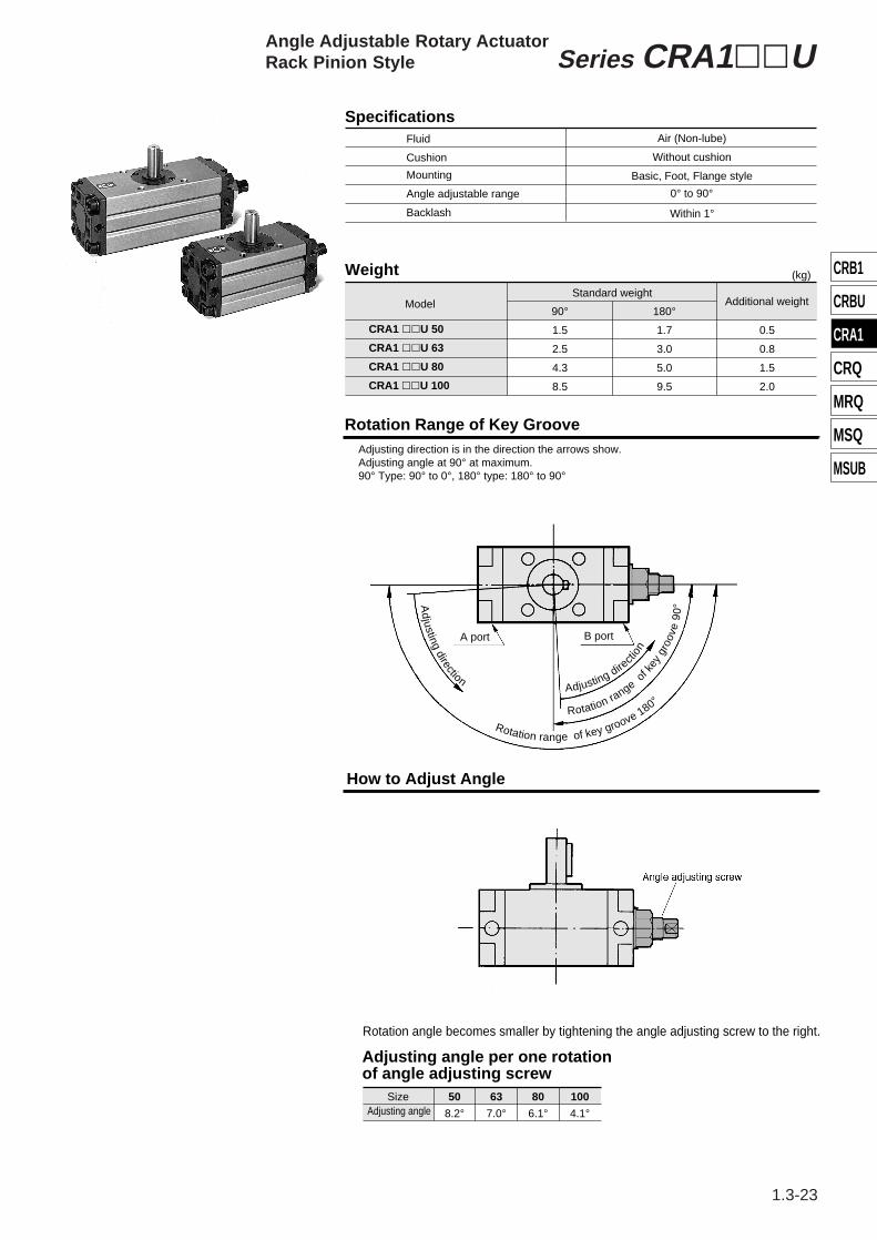
SpecificationsFluid
Cushion
Mounting
Angle adjustable range
Air (Non-lube)
Without cushion
Basic, Foot, Flange style
Weight
ModelStandard weight
90°
1.5
2.5
4.3
8.5
180°
1.7
3.0
5.0
9.5
Additional weight
0.5
0.8
1.5
2.0
(kg)
Backlash Within 1°
Rotation Range of Key GrooveAdjusting direction is in the direction the arrows show.Adjusting angle at 90° at maximum.90° Type: 90° to 0°, 180° type: 180° to 90°
A port B port
How to Adjust Angle
0° to 90°
CRA1 llU 50
CRA1 llU 63
CRA1 llU 80
CRA1 llU 100
°081evoorgyekfoegnarnoitatoRRotation range
ofke
ygr
oove
90
°Adjusting dire
ctio
n
noitce
rid
gnit
sujd
A
Rotation angle becomes smaller by tightening the angle adjusting screw to the right.
Size 50
8.2°63
7.0°80
6.1°100
4.1°
Adjusting angle per one rotation of angle adjusting screw
Adjusting angle
Angle Adjustable Rotary ActuatorRack Pinion Style Series CRA1llU
CRA1
CRB1
CRBU
CRQ
MRQ
MSQ
MSUB
CRA1 SERIES-1 2/16/99 9:47 AM Page 23

∗∗∗
1.3-24
No.
q
w
e
r
t
y
u
i
o
!0
!1
!2
!3
!4
Description
Body
Right cover
Left cover
Piston
Shaft
Parallel key
Slider
Connecting screw
Bearing retainer
Tube gasket
Piston seal
Bearing
Cross-recessed head cap screw
Material
Aluminum alloy
Carbon steel
Aluminum alloy
Aluminum alloy
Chromium-molybdenum steel
Carbon steel
Delrin
Carbon steel
Aluminum alloy
Chromium-molybdenum steel
NBR
NBR
Carbon steel
Steel wire
Note
Hard anodized
Black zinc anodized
Black anodized
Chromated
Zinc chromated
Black anodized
Black zinc anodized
Black zinc anodized
Component Parts Component PartsNo.
!5
!6
!7
!8
!9
@0
@1
@2
@3
@4
@5
@6
@7
@8
Description
Spring pin
Rack
Stopper
Stopper screw
O ring
Seal washer
E type stopper ring
Hexagon nut
Switch mounting rail
Auto switch
Plastic magnet
Cross-recessed head cap screw
Cross-recessed head cap screw
Hexagon nut
Material
Steel wire
Carbon steel
Carbon steel
Carbon steel
NBR
NBR
Steel wire
Steel wire
Aluminum alloy
Magnetic substance
Steel wire
Steel wire
Steel wire
Note
Nitrided
Zinc chromated
Black zinc anodized
Chromated
Nickel plated
Nickel plated
Nickel plated
Nickel plated
Size (Type) With angle adjuster, With angle adjuster and auto switch
Replacement Parts (The corresponding parts shown below are set.)
CRA1llU50
CRA1llU63
CRA1llU80
CRA1llU100
Corresponding parts
Construction
Standard/CRA1llU With auto switch/CDRA1llU
u,!1,!2,!5 and @0 are set.
Hexagon socket head capscrew with spring washer
P294020-22A
P294030-22A
P294040-22
P294050-22A
Series CRA1llU
CRA1 SERIES-1 2/16/99 9:47 AM Page 24

∗∗
1.3-25
SCRA1 , According to #4 (#4 + #16 + #17), auto switch (#16) is eliminated.
Single shaft style
Model
CRA1BSU50
CRA1BSU63
CRA1BSU80
CRA1BSU100
Port sizeRc(PT)
D(g6)
1/8
1/8
1/4
3/8
A
62
76
92
112
AU
15
19
22
22
B
48
60
72
85
BA
17
20
23.5
25
BB
8.5
10
12
12.5
BU
11
13
16
16
C
46
57
70
85
CU
9
11
13
13
DD(h9)
M8 X 1.25Depth 8
144(177)
163(201.5)
186(230)
245(311)
M10 X 1.5Depth 12
M12 X 1.75Depth 13
M12 X 1.75Depth 14
DU
14
18
22
22
EU
12
14
19
19
F
2.5
2.5
3
4
H
36
41
50
60
K
5
5
5
5
J S SU
45
54.5
62.5
73.5
U
98
117
142
172
W
17
19.5
22.5
28
MU
M16 X 1.5
M20 X 1.5
M24 X 1.5
M24 X 1.5
15
17
20
25
25
30
35
40
Key dimensionsb
5 0–0.030
6 0–0.030
6 0–0.030
8 0–0.036
l
25
30
40
45
Single shaft styleCRA1BSU ·········Double shaft styleCRA1BWU ·········
Size Size
SizeSize
SCRA1 , According to #3 (#3 + #16 + #17), auto switch (#16) is eliminated.
Double shaft style/CRA1BWUModel
CRA1BWU50 CRA1BWU63 CRA1BWU80 CRA1BWU100
D(g6)
15172025
L 14161924
M20222530
N15172025
UU118139167202
G11131519
Size 50, 63, 80, 100/Standard: CRA1llUSingle shaft style/CRA1BSU
∗The dimensions below show pressurization to B port.∗( ) are the dimensions for rotation of 180° and 190°.
CRA1
CRB1
CRBU
CRQ
MRQ
MSQ
MSUB
Angle Adjustable Rotary ActuatorRack Pinion Style Series CRA1llU
CRA1 SERIES-1 2/16/99 9:48 AM Page 25

∗∗
1.3-26
Other dimensions are the same as the single shaft.
ModelCRA1BXUl50CRA1BXUl63CRA1BXUl80CRA1BXUl100
H27293844
L14161924
N15172025
U89105130156
Other dimensions are the same as thesingle shaft.
ModelCRA1BZUl50CRA1BZUl63CRA1BZUl80CRA1BZUl100
H27293844
L14161924
M20222530
N15172025
U89
105 130 156
UU109 127 155 186
Other dimensions are the same as the single shaft.
ModelCRA1BYUl50CRA1BYUl63CRA1BYUl80CRA1BYUl100
l
25304045
H 36415060
K 5 5 5 5
UU134 158 192 232
G11131519
G11131519
Size 50,63,80,100Single shaft with four chamfers/CRA1BXUl
Double shaft/CRA1BYUl Double shaft with four chamfers/CRA1BZUl
Foot style/CRA1LlU
Model LA LB LC LD LE LF LH LT
CRA1LlU50
CRA1LlU63
CRA1LlU80
CRA1LlU100
62
76
92
112
9
11
13
13
44
55
67
87
41
48
58
73.5
108
127
154
189.5
4.5
5
6
6
200 (233)
224 (257)
235 (273.5)
274 (318)
333 (399)
263 (301.5)
316 (360)
375 (441)
Single shaft with four chamfersCRA1BXU Size ············SCRA1 Size , #13 (Rod only)Double shaftCRA1BYU Size ············SCRA1 Size , #14 (Rod only)Double shaft with four chamfersCRA1BZU Size ··········· SCRA1 Size , #15 (Rod only)
Single shaft angle adjustable foot CRA1LSU Size ·········· SCRA1 Size , According to #7 (#7+#16+#17), auto switch (#16) is eliminatedDouble shaft angle adjustable footCRA1LWU Size ········· SCRA1 Size , According to #8 (#8+#16+#17), auto switch (#16) is eliminated.
∗The dimensions below show pressurization to B port.∗( ) are the dimensions for rotation of 180o and 190o.
Other dimensions are the same as the single shaft.
Series CRA1llU
CRA1 SERIES-1 2/16/99 9:48 AM Page 26
∗∗
1.3-27
Other dimensions are the same as the single shaft.
Other dimensions are the same as the single shaft.
Other dimensions are the same as the single shaft.
Other dimensions are the same as the single shaft.
CRA1FWU50CRA1FWU63CRA1FWU80CRA1FWU100
H39455560
N15172025
U114136165190
UU134158190220
Model U105124153174
CRA1FXU50CRA1FXU63CRA1FXU80CRA1FXU100
H30334344
N15172025
ModelCRA1FYU50CRA1FYU63CRA1FYU80CRA1FYU100
H39455560
U114136165190
UU150177215250
ModelCRA1FZU50CRA1FZU63CRA1FZU80CRA1FZU100
H30334344
N15172025
U105124153174
Model
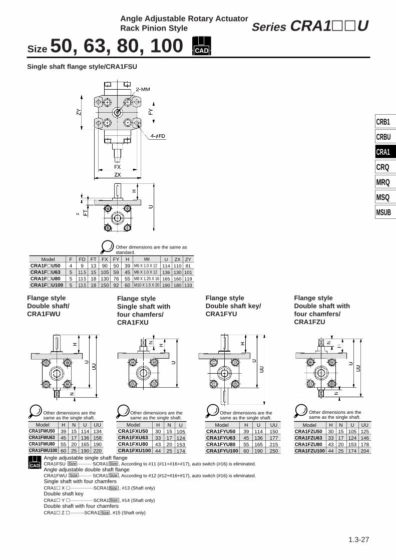
Angle adjustable single shaft flangeCRA1FSU ··········· SCRA1 , According to #11 (#11+#16+#17), auto switch (#16) is eliminated.Angle adjustable double shaft flangeCRA1FWU ·········· SCRA1 , According to #12 (#12+#16+#17), auto switch (#16) is eliminated.Single shaft with four chamfersCRA1l X l··················SCRA1 , #13 (Shaft only)Double shaft keyCRA1l Y l··················SCRA1 , #14 (Shaft only)Double shaft with four chamfersCRA1l Z l···········SCRA1 Size , #15 (Shaft only)
Size Size
Size Size
Size
Size
UU125146178204
CRA1FlU50CRA1FlU63CRA1FlU80CRA1FlU100
Model F4555
FD9
11.513.513.5
FT13151818
FX90
105130150
FY50597692
H39455560
MMM6 X 1.0 X 12 M6 X 1.0 X 12 M8 X 1.25 X 16M10 X 1.5 X 20
U114136165190
ZX110130160180
ZY81
101119133
Other dimensions are the same as standard.
Size 50, 63, 80, 100
Flange styleDouble shaft/CRA1FWU
Flange style Double shaft with four chamfers/CRA1FZU
Flange styleDouble shaft key/CRA1FYU
Flange styleSingle shaft withfour chamfers/CRA1FXU
Angle Adjustable Rotary ActuatorRack Pinion Style Series CRA1llU
CRA1
CRB1
CRBU
CRQ
MRQ
MSQ
MSUB
Single shaft flange style/CRA1FSU
CRA1 SERIES-1 3/3/99 10:45 PM Page 27

∗∗
1.3-28
Model
CDRA1BWU50CDRA1BWU63CDRA1BWU80CDRA1BWU100
øD (g6)15172025
11131519
20222530
15172025
118 139 167 202
14161924
lG M N UU øL
CDRA1BSU50
CDRA1BSU63
CDRA1BSU80
CDRA1BSU100
ModelPort sizeRc(PT)
øD(g6)
1/8
1/8
1/4
3/8
A
62
76
92
112
B
48
60
72
85
C
46
57
70
85
15
17
20
25
F
2.5
2.5
3
4
H
36
41
50
60
J K
5
5
5
5
S U
98
117
142
172
W
17
19.5
22.5
28
BA
17
20
23.5
25
BB
8.5
10
12
12.5
SA
33
33
33
33
SB
13.5
14.5
15.5
16
SC
12
12
12
12
SD
14
21
29
39
SE
34
34
34
34
Key dimensionsb l
AU
15
19
22
22
BU
11
13
16
16
CU
9
11
13
13
DU
14
18
22
22
EU
12
14
19
19
MU
M16 X 1.5
M20 X 1.5
M24 X 1.5
M24 X 1.5
øDD(h9)
25
30
35
40
M8 X 1.25Depth8
156(189)
0-0.030
175(213.5)
199(243)
259(325)
M10 X 1.5Depth12
M12 X 1.75Depth13
M12 X 1.75Depth14
5 25
30
40
45
0-0.0306
0-0.0306
0-0.0368
SU
45
54.5
62.5
73.5
l l l
Single shaft style/CDRA1BSU Double shaft style/CDRA1BWU
Foot style/CDRA1LSU Single shaft flange style/CDRA1FSU
LA øLB LC LD LE LF LH LTModel
CDRA1LSU50
CDRA1LSU63
CDRA1LSU80
CDRA1LSU100
212(245)
247(285.5)
287(331)
347(413)
236(269)
275(313.5)
329(373)
389(455)
62
76
92
112
9
11
13
13
44
55
67
87
41
48
58
73.5
108
127
154
189.5
4.5
5
6
6
FModel
CDRA1FSU50
CDRA1FSU63
CDRA1FSU80
CDRA1FSU100
4
5
5
5
H
39
45
55
60
MMM6 X 1.0
Depth12
M6 X 1.0Depth12
M8 X 1.25Depth16
M10 X 1.5Depth20
U
114
136
165
190
øFD
9
11.5
13.5
13.5
FT
13
15
18
18
FX
90
105
130
150
FY
50
59
76
92
ZX
110
130
160
180
ZY
81
101
119
133
∗The dimensions above show pressurization to B port.∗( ) are the dimensions for rotation of 180° and 190°Note) Other dimensions are the same as the single shaft.
Size
Size
Size
Size
Size
Size
Size
Size
Size
Size
Size
Size
Size
Size
Single shaft with four chamfersCRA1BXU ············SCRA1 , #13 (Shaft only)Double shaft keyCRA1BYU ············SCRA1 , #14 (Shaft only)Double shaft with four chamfersCRA1BZU ············SCRA1 , #15 (Shaft only)
Angle adjustable single shaft footCRA1LSU ············SCRA1 According to #7 (#7+#16+#17), auto switch (#16) is eliminated.Angle adjustable double shaft footCRA1LWU ·············SCRA1 According to #8 (#8+#16+#17), auto switch (#16) is eliminated.Angle adjustable single shaft foot with auto switchCDRA1LSU ·········SCRA1 , #7 (#7+#16+#17)Angle adjustable double shaft foot with auto switch.CDRA1LWU ········SCRA1 , #8 (#8+#16+#17)
Size 50,63,80,100
∗The dimensions above show pressurization to B port.∗( ) are the dimensions for rotation of 180° and 190°
Series CRA1llU
CRA1 SERIES-1 2/16/99 9:48 AM Page 28

∗∗
XA1 to XA24,XA33 to XA46,XC7 to XC11,XC30 to XC64
Applicable patternsSize
Pattern
30, 50, 63, 80, 100
Additional reminders• Enter the dimensions within a range that allows for
additional machining.• SMC will make appropriate arrangements if no
dimensions, tolerance, or finish instructions are given in the diagram.
• The length of the unthreaded portion is 2 to 3 pitches.• Unless specified otherwise, the thread pitch is based on
coarse metric threads. P = thread pitch M3 X 0.5, M4 X 0.7, M5 X 0.8, M6 X 1, M8 X 1.25, M10 X 1.5• Enter the desired values in the portion of the
diagram.• Consult SMC for made to order specifications other than
those mentioned in "How to Order".• Individual drawings for specific made to order models
may not be available. Consult SMC separately if drawings are needed.
A wide selection of models is now available, as non-standard shaft configurations for the CRA1 series rotary actuators are provided in 60 styles.
Without air cushionWith air cushion
CRA1
MountingBLF
BasicFootFlange
Shaft styleSWXYZT
J
K
Single shaft keyDouble shaft (Long shaft key & four chamfers)
Single shaft with four chamfersDouble shaft key
Double shaft with four chamfersSingle round shaft
Double shaft (Long shaft without key & with four chamfers)
Double round shaft
∗∗Refer to p.1.13-42 to 1.3-44 concerningfurther information on shafts X, Y, Z, T, J and K
Style—H
PneumaticAir-hydro
Provided in patterns
30506380100
90°100°180°190°
Size
Rotation angleC
A1L W P 50 90 X
Symbol for made to order specification
Pattern symbols for made to order
How to order model with auto switches
Refer to p1.3-16 concerning how to orderfor the solenoid valves equipped type.
Refer to p1.3-22 concerning how to orderfor the angle adjustable type.
Refer to p.1.3-11 concerning how to order forthe auto switch equipped type.
How to order angle adjustable style
How to order model with solenoid valve
Standard
Opt
ion
∗Size 30 is available as an made to order product.
Applicable patterns indicated in the above table.A1 to A24, A33 to A46C7 to C11, C30 to C64∗Refer to p1.3-30 for further information.
Air cushion
How to Order
∗
Change of shaft end shape1 Symbols
-XA1 to XA46
—
OrderMade
Series CRA1Made to Order SpecificationsChange of Shaft End Shape/-XA1 to XA46Consult SMC for further information on specifications, dimensions and delivery.
1.3-29
CRA1
CRB1
CRBU
CRQ
MRQ
MSQ
MSUB
CRA1 SERIES-2 2/16/99 10:34 AM Page 29

∗∗
-XA1
-XA2
-XA13
-XA14
-XA15
-XA16
-XA24
Shaft style/S (Single shaft), W (Double shaft), Y (Double shaft key)
Shaft style
Symbol
-XC7
-XC8
-XC9
-XC10
-XC11
-XC30
-XC31
-XC32
-XC33
-XC34
-XC35
-XC36
-XC37
-XC38
-XC39
-XC40
-XC41
-XC42
-XC43
-XC44
-XC45
-XC46
-XC47
-XC48
-XC49
-XC50
-XC51
-XC52
-XC53
-XC54
-XC55
-XC56
-XC57
-XC58
-XC59
-XC60
-XC61
-XC62
-XC63
-XC64
Symbol
Symbol Description
-XA33
-XA34
-XA35
-XA36
-XA37
-XA38
-XA40
-XA41
-XA43
-XA44
-XA45
-XA46
Female thread at the shaft end
Female thread at the shaft end
Female thread at the shaft end
Female thread at the shaft end
Round shaft with steps
Round shaft with steps
Shaft through-hole
Shaft through-hole
Shaft through-hole with female
Shaft through-hole with female
Intermediate chamfer
Description Description
Female thread at the shaft end
Female thread at the shaft end
Shaft through-hole
Shaft through-hole and female thread
Shaft through-hole and female thread
Shaft direction Shaft style
Shaft direction Shaft style
Upper LowerApplicable
sizeApplicable
size
30
50
63
80
100
Applicablesize
30
50
63
80
100
Upper
S W X Y Z T J K
Lower J K S T Y X Z
to
Shaft style
Shaft through-hole and female thread
Double key
Symbols
Reverse mounting of rotation shaft
Change of rotation range
Fluorine grease
Change of rotation range and shaft rotation direction
Change of rotation range and angle adjusting direction
Change of rotation range and angle adjusting direcation(Angle adjusting screw is equipped on the left.)
Change of port direction
Reverse mounting of auto switchOne side hydro, One side airOne side hydro, One side air
Applicable shaft style/Pattern combination table (Size: 30, 50, 63, 80, 100)
Intermediate chamfer
50
6380
100
50
6380
100
506380.100
30
100
Change of shaft end shape -XA1 to XA461
30 to 100
Series CRA1Made to Order SpecificationsChange of Shaft End Shape/-XA1 to XA46Consult SMC for further information on specifications, dimensions and delivery.
1.3-30
CRA1 SERIES-2 2/16/99 10:34 AM Page 30

∗∗
Symbol: A1 Symbol: A2
Symbol: A14Symbol: A13 Symbol: A15
Symbol: A24Symbol: A16 Symbol: A33
Note) Except for the flange style
Note) Except for the flange styleNote) Except for the flange style
Machine female threads into the long end of the shaft. (Shafts S, W and Y are additionally machined.)The L dimension (maximum) is, as a rule, twice the sizeof the bolt.
Note) Except for the flange style.Machine female threads into the short end of the shaft.(Shafts S, W and Y are additionally machined.)The L dimension (maximum) is, as a rule, twice the sizeof the bolt.
Note) Except for the flange style
Note) Except for the flange style
Double keysAdditionally machine a key groove at 180° from thestandard key position.(Shafts S, W, Y are additionally machined.)
Note) Except for the flange style
Machine female threads into the long end of the shaft.(Shafts J, K and T are additionally machined.)The L dimension (maximum) is, as a rule, twice the size of thebolt. (Example: For M3 bolt: L max. = 6mm)
30ø2.5———————
50—ø4ø5—————
63—
————
80———
—
100———
Size 30 50 63 80100
Size 30 50 63 80100
Size 30 50 63 80100
M3M4, M5, M6, M8M4, M5, M6, M8, M10M4, M5, M6, M8, M10, M12M5, M6, M8, M10, M12
Size 30 50 63 80100
ThreadM3 X 0.5M5 X 0.8M6 X 1M8 X 1.25M10 X 1.5M12 X 1.75Rc X PT1/8Rc X PT1/4
30ø2.5———————
50—ø4ø5—————
63—
ø4.3ø5.8ø6.8————
80 100———
ThreadM3 X 0.5M5 X 0.8M6 X 1M8 X 1.25M10 X 1.5M12 X 1.75Rc(PT) 1/8Rc (PT)1/4
Size
30ø2.5———————
50—ø4ø5—————
63—
————
———
ø 8 —
———
ThreadM3 X 0.5M5 X 0.8M6 X 1M8 X 1.25M10 X 1.5M12 X 1.75Rc (PT)1/8Rc (PT)1/4
SizeSize
Additional reminders
dø2.5
.
Size 30 50 63 80100
Key groove dimension L135555
M3M4, M5, M6M4, M5, M6M4, M5, M6, M8M5, M6, M8, M10
Q M3, M4M4, M5, M6M4, M5, M6M4, M5, M6, M8M5, M6, M8, M10
ø 6.8ø 8.5ø10.3ø 8ø11
ø 6.8ø 8.5ø10.3ø 8ø11
ø 6.8ø 8.5ø10.3ø 8ø11
Symbols
Q
Q
• Enter the dimensions within a range that allows for additional machining.
• SMC will make appropriate arrangements if no dimensional, tolerance, or finish instructions are given in the diagram.
• The length of the unthreaded portion is 2 to 3 pitches.
• Unless specified otherwise, the thread pitch is based on coarse metric threads.
P = thread pitch M3 X 0.5, M4 X 0.7, M5 X 0.8 M6 X 1, M8 X 1.25, M10 X 1.5• Enter the desired figures in the portion of the
diagram.• If not specified, the chamfer "C" is 0.5.
Machine a special end (at the short end of the shaft), and machine female threads in the through hole at the short end of the shaft, thus creating a through holes to serve as the pilot hole. (Shafts S, W, Y are additionally machined.)The L dimension (maximum) is, as a rule, twice the size of the bolt. (Example: For M4 bolt: L max. = 8mm)
Machine a special end (at the long end of the shaft), and machine female threads in the through-hole at the long end of the shaft, thus creating a through-holes to serve as the pilot hole. (Shafts S, W, Y are additionally machined.)The L dimension (maximum) is, as a rule, twice the size of the bolt. (Example: For M5 bolt: L max. = 10mm)
Machine special ends (at both the long and short ends of the shaft), and machine female threads in the through hole at both the long and short ends of the shaft, thus creating through holes to serve as pilot holes. (Shafts S, W, Y are additionally machined.)The L dimension (maximum) is basically twice the size of the bolt. (Example: For M5 bolt: L max. = 10mm)
Shaft through-hole (Shafts S, W, Y are additionally machined)Note) The minimum range of the machinable
dimension for the ød area is 0.1mm.
80 100
———
ø 6.8ø 8.5ø10.3ø 8
—
1 Change of shaft end shape -XA1 to XA33
ø4 to ø 7 ø4 to ø 8.5ø6.8 to ø11 ø6.8 to ø13
3 X 3 X 145 X 5 X 256 X 6 X 306 X 6 X 408 X 7 X 45
(Example: For M3 bolt: L max. = 6mm)
(Example: For M4 bolt: L max. = 8mm)
ø 6.8ø 8.5ø10.3ø 8
ø4ø5ø6.8
ø4ø5ø6.8 ø 6.8
ø 8.5ø10.3
Series CRA1Made to Order SpecificationsChange of Shaft End Shape/-XA1 to XA33Consult SMC for further information on specifications, dimensions and delivery.
1.3-31
CRA1
CRB1
CRBU
CRQ
MRQ
MSQ
MSUB
CRA1 SERIES-2 2/16/99 10:34 AM Page 31

Shaft through-hole and female thread(Shafts J, X and Z)(Shafts J, X and Z are additionally machined)
Size30506380
100
M3M4, M5, M6, M8M4, M5, M6, M8, M10M4, M5, M6, M8, M10, M12M5, M6, M8, M10, M12
X3 to 253.5 to 363.5 to 414 to 505 to 60
Lmax5
dø2.5
ø4 to ø 7.5ø4 to ø 8.5ø6.8 to ø11.5ø6.8 to ø13.5
Size 30 50 63 80100
Y1 to 251 to 361 to 411 to 501 to 60
LmaxYYYYY
Size 30 50 63 80100
Size 30 50 63 80100
dSize 30 50 63 80100
30ø2.5———————
50—ø4ø5—————
63—
ø4.3ø5.8ø6.8————
80———
100———
ThreadM3 X 0.5M5 X 0.8M6 X 1M8 X 1.25M10 X 1.5M12 X 1.75Rc(PT)1/8Rc(PT)1/4
Size30ø2.5———————
50—ø4ø5—————
63—
ø4.3ø5.8ø6.8————
80 100———
ThreadM3 X 0.5M5 X 0.8M6 X 1M8 X 1.25M10 X 1.5M12 X 1.75Rc(PT)1/8Rc(PT)1/4
Size
ø 6.8ø 8.5ø10.3ø 8.8ø11.3
Note) Except for flange style
Machine threads into the short end of the shaft.(Shafts X and Z additionally machined)The L dimension (maximum) is, as a rule, twice the sizeof the bolt.(Example: For M3 bolt: L = 6)
Symbols
Symbol: A36Note) Except for flange style
Machine female threads into the long end of the shaft.(Shafts X and Z additionally machined)The L dimension (maximum) is, as a rule, twice the sizeof the bolt. (Example: For M3 bolt: L = 6)
Symbol: A35Note) Except for flange style
Machine female threads into the short end of the shaft.(Shafts J, K and T additionally machined)The L dimension (maximum) is, as a rule, twice the sizeof the bolt.(Example: For M3 bolt: L = 6)
Symbol: A34
Note) Except for flange styleSymbol: A37 Note) Except for flange styleSymbol: A38
Note) Except for flange styleSymbol: A44
Shaft through-hole(Shafts K and T are additionally machined)
Note) Except for flange styleSymbol: A40
Shaft through-hole(Shafts J, X and Z are additionally machined)
Note) Except for flange styleSymbol: A41Shaft through-hole and female thread(Shafts K and T are additionally machined)
Note) Except for flange styleSymbol: A43
The shaft can be further shortened by machining a round shaft with steps on the short end of the shaft.(Shaft K are additionally machined)(If the shaft is not to be shortened, leave the Y dimension blank)
The shaft can be further shortened by machining a round shaft with steps on the long end of the shaft.(Shafts J, K and T are additionally machined)(If the shaft is not to be shortened, leave the X dimension blank)
Q Size30506380
100
M3M4, M5, M6, M8M4, M5, M6, M8, M10M4, M5, M6, M8, M10, M12M5, M6, M8, M10, M12
Q Size30506380
100
M3M4, M5, M6, M8M4, M5, M6, M8, M10M4, M5, M6, M8, M10, M12M5, M6, M8, M10, M12
Q
1 Change of shaft end shape -XA34 to XA44
X—2 .5X—2.5X—2.5X—3 5X—4.
———
ø 6.8ø 8.5ø10.3ø 8
—
ø 6.8ø 8.5ø10.3ø 8ø11
ø 6.8ø 8.5ø10.3ø 8
—
ø2.5ø4 to ø 7.5ø4 to ø 8.5ø6.8 to ø11.5.5ø6.8 to ø13 5
Series CRA1Made to Order SpecificationsChange of Shaft End Shape/-XA34 to XA44Consult SMC for further information on specifications, dimensions and delivery.
∗∗
1.3-32
CRA1 SERIES-2 2/16/99 10:34 AM Page 32

∗∗
Symbol: A45
L1-2L1-2L1-2L1-3L1-4
Size X1 to 21 to 5.5 1 to 6.5 1 to 81.5 to 10.5
X – 2X – 2.5X – 2.5X – 3X – 4
8.5 to 2512.5 to 3613.5 to 4116.5 to 5021 to 60
W L1max L2max30506380
100
L1-2L1-2L1-2L1-3L1-4
Size Y1 to 21 to 5.5 1 to 6.5 1 to 81.5 to 10.5
W L1maxYYYYY
L2max30506380
100
6.5 to 2510 to 3611 to 4113.5 to 5017 to 60
Symbol: A46
Symbol: C8 Symbol: C9
Symbol: C10 Symbol: C11
The rotation range is changed. The rotation range is changed.
The rotation range is changed. The rotation range is changed.
Additional reminders
Applicable size
Applicable shaft style
50, 63, 80, 100
Shaft S, W, Y
Specification SymbolXC8 to -XC11
CRA1 →Refer to the "How to Order" on p.1.3-29. XC8
Note) Except for the flange style.
Note) Except for the flange style.
• Enter the dimensions within a range that allows for additional machining.
• SMC will make appropriate arrangements if no dimensions, tolerance, or finish instructions are given in the diagram.
• Enter the desired figures in the portion of the diagram.
The shaft can be further shortened by machining an intermediate flat on the long end of the shaft (the position is that of the standard flat, the key groove part).(Shafts J, K and T are additionally machined.)
The shaft can be further shortened by machining an intermediate chamfering on the short end of the shaft (the position is that of the standard chamfering, the key groove part).(Shaft K is additionally machined.)
Note) If it is pressurized from the port indicated with the arrow, the shaft rotates in the clockwise direction.
Note) If it is pressurized from the port indicated with the arrow, the shaft rotates in the clockwise direction.
Note) If it is pressurized from the port indicated with the arrow, the shaft rotates in the clockwise direction.
Note) If it is pressurized from the port indicated with the arrow, the shaft rotates in the clockwise direction.
1
Symbols
2
Symbols
The patterns with the rotation angle of 90° and 180° are applicable to the respective patterns with the rotation angles of 100° and 190° of the Made to order specifications.
Made to Order SpecificationsChange of Shaft End Shape/-XA45 to -XA46Change of Rotation Range (Size 50 to 100) /-XC8 to -XC11
Rotationrange
of key groove 90° +40
Rotation range of key groove90°
+40
Rotation range of key groove180° +40
Rot
atio
nra
nge
ofke
y groove 90° +40
1 Change of shaft end shape -XA45, XA462 Change of rotation range -XC8 to XC11
Consult SMC for further information on specifications, dimensions and delivery.
Series CRA1
1.3-33
CRA1
CRB1
CRBU
CRQ
MRQ
MSQ
MSUB
CRA1 SERIES-2 2/16/99 10:34 AM Page 33

∗∗∗
Made to Order SpecificationsReverse Mounting of Rotation Shaft (Size: 50 to 100) /-XC7Change of Rotation Range (Size: 30 to 100) /-XC30Consult SMC for further information on specifications, dimensions and delivery.
Series CRA1
CRA1 XC7
Reverse mounting of rotation shaft (-XC7)
Applicable size
Applicable shaft style50, 63, 80, 100
Shaft S, W, X, T, J
Specifications
Symbol: C7
Note) Shafts turns into the clockwise direction by pressurizingto the port indicated with arrows.
Specifications
Applicable shaft style
30, 50, 63, 80, 100
S, W, X, Y,Z, T, J, K
Applicable size
∗Refer to p.1.3-3 for other specifications.∗∗Except for air-hydro type.
Lubricant oil in the seal part of packing and inner wall of the cylinder is changed to fluorine type.
CRA1 XC30
Fluorine grease
→Refer to p.1.3-29 for "How to Order".
Rotation range of keygroove
90 o+4 0
Symbol Symbol
→Refer to p.1.3-29 for "How to Order".
3 4Reverse mounting of rotation shaft -XC7 Fluorine grease -XC30
1.3-34
CRA1 SERIES-2 2/16/99 10:34 AM Page 34

∗∗
Made to Order SpecificationsChange of Rotation Range and Rotation Direction of Shaft/-XC31 to -XC36Consult SMC for further information on specifications, dimensions and delivery.
Series CRA1 (Size 50 to 100)
Symbol: C35
50, 63, 80, 100
Shaft S, W, Y
SpecificationApplicable size
Applicable shaft style
The patterns with the rotation angle of 90° and 180° are applicable to the respective patterns with the rotation angles of 100° and 190° of the Made to order specification.
CRA1 →Refer to the "How to Order" on p.1.3-29. XC31
The rotation range and the rotation direction of the shaft are changed. (-XC31 to -XC36)
0
Symbol: C31 Symbol: C32 Symbol: C33
Rot
atio
nra
nge
ofke
y groove
90° +40 Rotation range of key
groove90°
+40Rota
tion range of key groove 180° +4
0
Rotation range ofke
ygr
oove
90°
+4 0
Rotation range of key groove 180°+4
0
Symbol: C36Symbol: C34
Note) If it is pressurized to the port indicated with the arrow, the shaft rotates in the clockwise direction.
The rotation range is changed and the rotating direction is reversed.
The rotation range is changed and the rotating direction is reversed.
The rotation range is changed and the rotating direction is reversed.
The rotation range is changed and the rotating direction is reversed.
The rotation range is changed and the rotating direction is reversed.
The rotation range is changed and the rotating direction is reversed.
Rotation
rangeof key groove 90° +4
0
Symbols
Change of the rotation range and the rotation direction of shaft -XC31 to XC365
Note) If it is pressurized to the port indicated with the arrow, the shaft rotates in the clockwise direction.
Note) If it is pressurized to the port indicated with the arrow, the shaft rotates in the clockwise direction.
Note) If it is pressurized to the port indicated with the arrow, the shaft rotates in the clockwise direction.
Note) If it is pressurized to the port indicated with the arrow, the shaft rotates in the clockwise direction.
Note) If it is pressurized to the port indicated with the arrow, the shaft rotates in the clockwise direction.
1.3-35
CRA1
CRB1
CRBU
CRQ
MRQ
MSQ
MSUB
CRA1 SERIES-2 2/16/99 10:35 AM Page 35

∗∗
CRA1 →Refer to the "How to Order" on p.1.3-29. XC37
The rotation range and the angle adjusting direction are changed. (-XC37 to XC42)
50, 63, 80, 100
Shaft S, W, Y
SpecificationApplicable size
Applicable shaft style
The patterns with the rotation angle of 90° and 180° are applicable to the respective patterns with the rotation angles of 100°and 190° of the Made to order specification.
Angle adjusting direction
The rotation range under the adjustment of an angle at 60° is indicated below. The rotation range under the adjustment of an angle at 60° is indicated below. The rotation range under the adjustment of an angle at 60° is indicated below.
Note) If it is pressurized to the port indicated with the arrow, the shaft rotates in the clockwise direction.
Note) If it is pressurized to the port indicated with the arrow, the shaft rotates in the clockwise direction.
Note) If it is pressurized to the port indicated with the arrow, the shaft rotates in the clockwise direction.
Rotat
ionran
geof k
eygroove 90°
Rotat
ionran
geof k
ey groove 90°
Ang
lead
justi
ngdirection
Rotation range of key groove90°
Rota
tion ran
ge
Ro
tation range Rotation range
Symbol: C37 Symbol: C38 Symbol: C39
The rotation range under the adjustment of an angle at 60° is indicated below. The rotation range under the adjustment of an angle at 60° is indicated below. The rotation range under the adjustment of an angle at 60° is indicated below.
Note) If it is pressurized to the port indicated with the arrow, the shaft rotates in the clockwise direction.
Note) If it is pressurized to the port indicated with the arrow, the shaft rotates in the clockwise direction.
Note) If it is pressurized to the port indicated with the arrow, the shaft rotates in the clockwise direction.
Rotation range of keygro
ove 90
°
Rotation range of key groove 90°
Rotation range of key groove 90°
Rotation range
Angle
adjusting range
Angleadju
stin
gdi
rect
ion A
ngleadjusting
direction
The rotation range and the angle adjusting directionof the angle adjustable style are changed.
The rotation range and the angle adjusting directionof the angle adjustable style are changed.
The rotation range and the angle adjusting directionof the angle adjustable style are changed.
The rotation range and the angle adjusting directionof the angle adjustable style are changed.
Rotation range
The rotation range and the angle adjusting directionof the angle adjustable style are changed.
The rotation range and the angle adjusting directionof the angle adjustable style are changed.
Symbol: C40 Symbol: C41 Symbol: C42
Angle adjustingdirection
Ang
lead
justing direction
Rotation range
Symbols6 Change of rotation range and the angle adjusting direction -XC37 to XC42
Made to Order SpecificationsChange of Rotation Range and Angle Adjusting Direction/-XC37 to -XC42Consult SMC for further information on specifications, dimensions and delivery.
Series CRA1 (Size 50 to 100)
1.3-36
CRA1 SERIES-2 2/16/99 10:35 AM Page 36

∗∗
The rotation range under the adjustment of an angle at 120° is indicated below
Note) If it is pressurized to the port indicated with the arrow, the shaft rotates in the clockwise direction.
Rotation range of the key groove 180°
Rotationrange
CRA1 →Refer to the "How to Order" on p.1.3-29. XC43
The rotation range and the angle adjusting direction are changed. (-XC43 to XC46)
50, 63, 80, 100
Shaft S, W, Y
SpecificationApplicable size
Applicable shaft style
The patterns with the rotation angle of 90° and 180° are applicable to the respective patterns with the rotation angles of 100° and 190° of the Made to order specification.
Symbol: C43 Symbol: C44 Symbol:C45
The rotation range under the adjustment of an angle a 60° is indicated below
The rotation range under the adjustment of an angle at 120° is indicated below
The rotation range under the adjustment of an angle at 120° is indicated below
Note) If it is pressurized to the port indicated with the arrow, the shaft rotates in the clockwise direction.
Note) If it is pressurized to the port indicated with the arrow, the shaft rotates in the clockwise direction.
Note) If it is pressurized to the port indicated with the arrow, the shaft rotates in the clockwise direction.
The rotation range and the angle adjusting direction of the angle adjustable style are changed.
The rotation range and the angle adjusting direction of the angle adjustable style are changed.
The rotation range and the angle adjusting direction of the angle adjustable style are changed.
Symbol: C46The rotation range and the angle adjusting direction of the angle adjustable style are changed.
Rotation range of the key groove90°
Angle adjusting direction
Rotation range of the key groove 180°Angle
adju
stin
gdi
rect
ion
Rota
tion range of key groove 180°
Angle adjustingdirection
Rotation range
Rot
ationrange
Ang
leA
djus
ting
direction
Symbols6 Change of rotation range and angle adjusting direction -XC43 to XC46
Made to Order SpecificationsChange of Rotation Range and Angle Adjusting Direction/-XC43 to -XC46Consult SMC for further information on specifications, dimensions and delivery.
Series CRA1 (Size 50 to 100)
Rotationrange
1.3-37
CRA1
CRB1
CRBU
CRQ
MRQ
MSQ
MSUB
CRA1 SERIES-2 2/16/99 10:35 AM Page 37

∗∗
CRA1 →Refer to the "How to Order'' on p.1.3-29. XC47
The rotation range and the angle adjusting direction are changed. (-XC47 to XC52)
50, 63, 80, 100
SpecificationApplicable size
Applicable shaft style
The patterns with the rotation angle of 90° and 180° are applicable to the respective patterns with the rotation angles of 100° and 190° of the Made to order specification.
Symbol: C47For the angle adjusting style, angle adjusting screwsare mounted to the left cover.
For the angle adjusting style, angle adjusting screwsare mounted to the left cover.
For the angle adjusting style, angle adjusting screws are mounted to the left cover.
For the angle adjusting style, angle adjusting screws are mounted to the left cover.
For the angle adjusting style, angle adjusting screws are mounted to the left cover.
The rotation range under the adjustment of an angle at 60° is indicated below
The rotation range under the adjustment of an angle at 60° is indicated below
The rotation range under the adjustment of an angle at 60° is indicated below
The rotation range under the adjustment of an angle at 60° is indicated below
Shaft S, W, Y
Symbol: C48 Symbol: C49
Symbol: C50 Symbol: C51 Symbol: C52
For the angle adjusting style, angle adjusting screwsare mounted to the left cover.
The rotating range under the adjustment of an angle at 60° is indicated below
The rotating range under the adjustment of an angle at 60° is indicated below
Note) If it is pressurized to the port indicated with the arrow, the shaft rotates in the clockwise direction.
Note) If it is pressurized to the port indicated with the arrow, the shaft rotates in the clockwise direction.
Note) If it is pressurized to the port indicated with the arrow, the shaft rotates in the clockwise direction.
Note) If it is pressurized to the port indicated with the arrow, the shaft rotates in the clockwise direction.
Note) If it is pressurized to the port indicated with the arrow, the shaft rotates in the clockwise direction.
Note) If it is pressurized to the port indicated with the arrow, the shaft rotates in the clockwise direction.
7
Rotation range of the keygro
ove 9
0°
Angle adjusting
dire
ctio
n
Angleadju
stin
gdi
rect
ion
Rotation range
ofthe
key g
roov
e90
°
Angle
adjustingrange
Rotation range of the key groove 90°
Rotation
range
Rotation range Rotation range
Rotation
range of the key groove 90°
Angle
adjusting direction
Rot
atio
nra
nge of
the
key groove 90°
Rot
atio
nra
nge
ofthe
key groove
90°
Ang
lead
justing direction
Ang
lead
just
ing
directio
n
Rotationrange
Rotat
ionran
ge
Rotati
on range
Symbols7 Change of rotation range and angle adjusting direction (Angle adjusting screw moved to the left) -XC47 to XC52
Angle adjusting screw moved to the left
Series CRA1 Made to Order SpecificationsChange of Rotation Range and Angle Adjusting Direction /-XC47 to XC52Consult SMC for further information on specifications, dimensions and delivery.
1.3-38
CRA1 SERIES-2 2/16/99 10:36 AM Page 38

∗∗
Rotation range of the key groove90°
Rotation range of the key groove90°
Angle adjustingdirection
Angle adjustingdirection
Angle adjustingdirection
Rotation range of the key groove 180°
Rotation range
Rotation range
Rotat
ionrange
The rotation range under the adjustment of an angle at 60° is indicated below.
The rotation range under the adjustment of an angle at 120° is indicated below.
The rotation range under the adjustment of an angle at 120° is indicated below.
The rotation range under the adjustment of an angle at 120° is indicated below.
For the angle adjusting style, angle adjusting screwsare mounted to the left cover.
The rotation range under the adjustment of an angle at 60° is indicated below.
For the angle adjusting style, angle adjusting screwsare mounted to the left cover.
The rotation range under the adjustment of an angle at 120° is indicated below.
CRA1 →Refer to the "How to Order'' on p.1.3-29. XC53
The rotation range and the angle adjusting direction of the shaft are changed. (-XC53 to XC58)
50, 63, 80, 100
SpecificationApplicable size
Applicable shaft style
The patterns with the rotation angle of 90° and 180° are applicable to the respective patterns with the rotation angles of 100° and 190° of the Made to order specification.
Shaft S, W, Y
Symbol: C53
Symbol: C56
For the angle adjusting style, angle adjusting screwsare mounted to the left cover.
For the angle adjusting style, angle adjusting screwsare mounted to the left cover.
For the angle adjusting style, angle adjusting screwsare mounted to the left cover.
For the angle adjusting style, angle adjusting screwsare mounted to the left cover.
Symbol: C54
Symbol: C57 Symbol: C58
Symbol: C55
Note) If it is pressurized to the port indicated with the arrow, the shaft rotates in the clockwise direction.
Note) If it is pressurized to the port indicated with the arrow, the shaft rotates in the clockwise direction.
Note) If it is pressurized to the port indicated with the arrow, the shaft rotates in the clockwise direction.
Note) If it is pressurized to the port indicated with the arrow, the shaft rotates in the clockwise direction.
Note) If it is pressurized to the port indicated with the arrow, the shaft rotates in the clockwise direction.
Note) If it is pressurized to the port indicated with the arrow, the shaft rotates in the clockwise direction.
Rotation range of the key groove 180°
Ang
lead
just
ingdirection
Angle
adjusting directionRotation range of the key groove 180° Rotation range of the key groove 180°Angle adjusti
ngdi
rect
ion
Rotation range
Rotation range
Rotati on range
7Symbols
7 Change of rotation range and angle adjusting direction (Angle adjusting screw moved to the left) -XC53 to XC58
Angle adjusting screw moved to the left.
Series CRA1 Made to Order SpecificationsChange of Rotation Range and Angle Adjusting Direction /-XC53 to XC58Consult SMC for further information on specifications, dimensions and delivery.
1.3-39
CRA1
CRB1
CRBU
CRQ
MRQ
MSQ
MSUB
CRA1 SERIES-2 2/16/99 10:36 AM Page 39

∗∗
CRA1 XC59
Specification30, 50, 63, 80, 100
Symbol: C59Direction of the port is changed. (upwards) Direction of the port is changed. (downwards) Direction of the port is changed. (backwards)
CRA1 XC62→Refer to the "How to Order'' auto switch equipped type on p.1.3-11.
The auto switch is reverse mounted to the standard.
The patterns with the rotation angle of 90o and 180o are applicable to the respective patterns with the rotation angles of 100o and 190o of the Made to order specification.For the bumper equipped type, the needle position is on the opposite side of the port.
→Refer to the "How to Order'' on p.1.3-29.
Port position is changed.(-XC59 to -XC61)
Applicable size
Applicable shaft style Shaft S, W, X, Y, Z, T, J, K
Symbol: C60
Symbol: C62
Symbol: C61
∗Except for the solenoid valve equipped style.
Symbols8 Change of port position (Mounting location of the cover is changed.) -XC59 to XC61
Symbol9 Reverse mounting of the auto switch against the standard -XC62
Made to Order SpecificationsChange of Port Position (Size 30 to 100)/-XA59 to XA61Reverse Auto Switch Mounting (Size 50 to 100) /-XC62Consult SMC for further information on specifications, dimensions and delivery.
Series CRA1
1.3-40
CRA1 SERIES-2 2/16/99 10:36 AM Page 40

∗∗
CRA1 →Refer to the "How to Order" on p.1.3-29. XC63
One side air-hydro, One side air-XC63: Left side air Right side air-hydro-XC64: Left side air-hydro Right side air
SpecificationsApplicable size
Applicable shaft style
50, 63, 80, 100
S, W, X, YZ, T, J, K
The patterns with the rotation angle of 90°and 180° are applicable to the respective patterns with the rotation angles of 100°and 190° of the Made to order specification.
∗Except for the solenoid valve equipped type, angle adjustable type and air cushion equipped type.
The figure shows the pressurized situation to the hydro pressure port. The figure shows the pressurized situation to the air pressure port.
Symbol: C63One side air, one side air-hydro specifications (Left side air, right side hydro)
Symbol: C64One side air, one side air-hydro specifications (Left side hydro, right side air)
Shaft
Symbols10 One side air-hydro, One side air style -XC63, -XC64
Made to Order SpecificationsOne Side Air-hydro, One Side Air Style/-XC63 to XC64Consult SMC for further information on specifications, dimensions and delivery.
Series CRA1 (Size 50 to 100)
1.3-41
CRA1
CRB1
CRBU
CRQ
MRQ
MSQ
MSUB
CRA1 SERIES-2 2/16/99 10:37 AM Page 41

∗∗
Refer to "How to Order" on p.1.3-2 and 1.3-11 for further information.
ClRA1 Mounting Shaft style Rotation30
Shaft styleT
J
K
Single round shaftDouble shaft (Long shaft without
key & with four chamfers)Double round shaft
Specifications
Style
Size
Shaft style
Cushion
Auto switch
Pneumatic∗
30
Single round rod end (T), Double round rod end (K),Double rod end/(w/o long rod end key & with four chamfers) (J)
Without cushion
Mountable
Mounting style Basic, Foot
∗Refer to p.1.3-3 for other specifications.
Dimensions
T (Single round shaft)Shaft style
Shape
K(Double round shaft)J (Double round shaft/Long shaft without key & with four chamfers)
(mm)
ø8g6 ø8g6 ø8g6
ø8g6
25 25 25
75
10 90
25
Symbols11 Without key groove (Shaft style variations) Shaft style: T, J, K
Made to Order SpecificationsWithout Key Groove (Shaft Style Variations)/Shaft Style: T, J, KConsult SMC for further information on specifications, dimensions and delivery.
Series CRA1 (Size 30)
1.3-42
CRA1 SERIES-2 2/16/99 10:37 AM Page 42

∗∗
ClRA1 Shaft style Size Rotation
Shaft styleT
J
K
Single round shaftDouble shaft (Long shaft without
key and with four chamfers)
Refer to "How to Order" onp.1.3-2, 1.3-11, 1.3-16 and 1.3-22.
Air cushion
—C
Without cushionWith air cushion
Mountable
SpeicificationsStyle
SizeFluid
Shaft style
CushionAuto switchMounting style
Pneumatic Air-hydro50, 63, 80, 100
Air (Non-lube) Hydric oilSingle round shaft (T), Double round shaft (K), Double shaft/Long shaft without key and with fourchamfers (J)
Not attached Not attached
∗ Refer to p.1.3-9 and 1.3-10 for other specifications.
Dimensions (mm)
Shaft style
Shape
Size
50
63
80
100
T(Single round shaft)
D(g6)
15
17
20
25
H
36
41
50
60
J(Double shaft/Long shaft without key & with four chamfers)
D(g6)
15
17
20
25
H
36
41
50
60
M
20
22
25
30
N
15
17
20
25
UU
118
139
167
202
K(Double round shaft)
D(g6)
15
17
20
25
H
36
41
50
60
UU
134
158
192
232
Mounting
Basic, Foot
Double round shaft
Note) Except for flange style.∗Refer to p.1.3-3 for other specifications.
øD
H
øD
N M
UU
H HH
øD
øD
Symbols12 Without key groove (Shaft Variations) Shaft style: T, J, K
Made to Order SpecificationsWithout Key Groove (Shaft Style Variations)/Shaft Style: T, J, KConsult SMC for further information on specifications, dimensions and delivery.
Series CRA1 (Size 50 to 100)
1.3-43
CRA1
CRB1
CRBU
CRQ
MRQ
MSQ
MSUB
CRA1 SERIES-2 2/16/99 10:37 AM Page 43

∗∗
ClRA1 Shaft style 30 Rotation
Refer to "How to Order" on p.1.3-2 and 1.3-11.
Single shaft keySingle shaft with four chamfersDouble shaft keyDouble shaft with four chamfers
Shaft style SXYZ
Six shaft types other than standard shaft type W (Double shaft) of size 30 are made into patterns.
Style
Size
Max. operating pressure
Min. operating pressure
Shaft style
Mounting
Auto switch
Specifications
Pneumatic
30
1MPa
0.1MPa
Basic, Foot
Mountable
∗Refer to p.1.3-3 for other specifications.
S(Single shaft key)
X(Single shaft with four chamfers) Y(Double shaft key) Z(Double shaft with four chamfers)
ø7.8
ø7.8
ø7.8
l6 l6
l6
13
53
ø8g6
ø8g6
2525
90
1310
63
25
65
Mounting
Symbols13 Shaft variations Shaft style: S, X, Y, Z
Single shaft key (S), Double shaft with four chamfers (X), Double shaft key (Y), Double shaft with four chamfers (Z)
Made to Order SpecificationsShaft Variations/Shaft Style: S, X, Y, ZConsult SMC for further information on specifications, dimensions and delivery.
Series CRA1 (Size 30)
1.3-44
CRA1 SERIES-2 2/16/99 10:37 AM Page 44

∗∗
Refer to the "How to Order" on p.1.3-2, 1.3-11 and 1.3-16. Refer to the "How to Order" on p.1.3-2 and 1.3-22.C RA1 X6S
Stainless steelfor main part
X7
Heat resistant style
CRA1
SpecificationsStyle
Size
Fluid
Max. operating pressure
Min. operating pressure
Stainless steel part
Pneumatic
30, 50, 63, 80, 100Air (Non-lube)
1MPa
0.1MPa
Shaft, Bolt, Parallel key
∗Specifications other than indicated above are the same as that shown on p.1.3-3.∗∗Except for the angle adjustable style.
Cushion
Auto switch
30—Without cushion
Mountable
∗Specifications other than indicated above are the same as that shown on p.1.3-3.∗∗Except for models with solenoid valve.
∗Specifications other than indicated above are the same as that shown on p.1.3-3.∗∗Except for models with solenoid valve.
30 — Without cushion
Specifications
Cushion
Auto switch
Rotation
Ambient and fluid temperature
Lubrication
Seal material
Shaft style
90°, 180° (Size 30 to 100)100°, 190° (Size 50 to 100)
0 to 100°C
ISO VG32
Fluorine rubber
Symbol
For applications in areas that pose a risk of rust or corrosion, a portion of the materials used in the standard parts has been changed to stainless steel.
In this rotary actuator, the material of the seals has been changed to the heat resistant type (to withstand up to 100°C), for applications in environments that exceed the standard specification temperatures of 0 to 60°C.
Style
Size
Pneumatic
30, 50, 63, 80, 100
Single shaft, Double shaft, Single shaft with four chamfers, double shaft key, Double shaft four chamfers Double round shaft, Double shaft (Round shaft, With four chamfers), Double round shaft
50 to 100 —With or without air cushion
Not mountable
CDRA1 – X16Refer to the "How to Order" on p.1.3-11 and 1.3-22.
Seal is now changed to fluoro rubber.Fluorine rubber seal
Style
Size
Fluid
Max. operating pressure
Min. operating pressure
30 — Not equipped
Specifications
Cushion
Auto switch
Ambient and fluid temperature
Seal material
Pneumatic
30, 50, 63, 80, 100Air (No lubrication)
1MPa
0.1MPa
0°C to 60°C (No condensation)
Fluorine rubber
Mountable
50 to 100 — Note equipped, With air cushion
50 to 100—With or without air cushion
14 Stainless steel for main part -X6Symbol15 Heat resistant style -X7
Symbol16 -X16Fluorine rubber seal
Made to Order SpecificationsStainless Steel for Main Part/-X6Heat Resistant Style/-X7Consult SMC for further information on specifications, dimensions and delivery.
Series CRA1
1.3-45
CRA1
CRB1
CRBU
CRQ
MRQ
MSQ
MSUB
CRA1 SERIES-2 2/16/99 10:37 AM Page 45

∗∗
Refer to "How to Order" on p.1.3-22.
UMounting Shaft style Size U-X10
Two sides angle adjustable style
Refer to "How to Order" on p.1.3-22.
UMounting Shaft style Size Rotation C-X11ClRA1ClRA1
One side angle adjuster and one side cushion style
Sepecifications
Cushion
Variations
Without cushion
With auto switch, With solenoid valve∗Refer to p.1.3-3 for other specifications.
Style
Size
Rotation
Shaft style
Pneumatic
50, 63, 80, 100 90o, 180o,100o,190o
Sepecifications
Cushion
Auto switch
Variations
Type
Size
Rotation
Shaft type
Pneumatic
50, 63, 80, 100 90o, 180o,100o,190o
With cushion on one side
Mountable
With auto switch, With solenoid valve
∗Refer to p.1.3-3 for other specifications.
Adjusting direction "A": When angle adjusting screw on "A" side is screwed in to the right direction.Adjusting direction "B": When angle adjusting screw on "B" side is screwed in to the right direction.
Rotation
Rotation at 180o
∗ Refer to p.1.3-9 and 1.3-10 for dimensions.
Rotation at 90o
Symbol17 -X10Symbol18-X11Both sides angle adjustable Style One side angle adjustable, One side cushion style
Adjusting direction
Single shaft (S), Double shaft (W), Single shaft with four chamfers (X), Double shaft key (Y), Double shaft with four chamfers (Z), Single round shaft (T), Double shaft/Round shaft, four chamfers (J), Double round shaft (K)
Single shaft (S), Double shaft (W), Single shaft with four chamfers (X), Double shaft key (Y), Double shaft with four chamfers (Z), Single round shaft (T), Double shaft/Round shaft, Four chamfers (J), Double round shaft (K)
Made to Order SpecificationsBoth Sides Angle Adjustable Style/-X10One Side Angle Adjustable, One Side Cushion Style/-X11Consult SMC for further information on specifications, dimensions and delivery.
Series CRA1
1.3-46
CRA1 SERIES-2 2/16/99 10:37 AM Page 46