rotary airlock - kice, industries – your air. custom directed.kice.com/pdfs/airlock manual.pdf ·...
TRANSCRIPT
1Kice industries, inc.
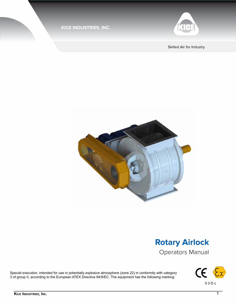
Operators ManualRotary Airlock
Skilled Air for Industry
II 3 D c
2Kice industries, inc.
1. IntroductIon
When you purchased your new Kice Airlock, you bought a dependable and quality-built product. The ten basic series of airlocks manufactured by Kice, and the range of options and materials, should satisfy nearly every conceivable industrial airlock need. We are proud of our products and the people at Kice who build them. At Kice, we start in our own foundry and follow the design and manufacturing standards that have proven superior over the last 60 years. This owner’s manual is intended as a guide for proper installation, operation and maintenance to keep your Kice airlock operating safely and efficiently on the job. Service and factory reconditioning information is also included for your benefit.
Sincerely,
Drew KicePresident Kice Industries, Inc.
Warranty
The company warrants the equipment manufactured by the Company to be free of defects in material and workmanship for a period of one year from the date of shipment. Company agrees to repair or replace, at its option, any parts found to be defective in the opinion of the Company. Company is not liable for any costs in connection with the removal, shipment or reinstallation of said parts. This warranty does not apply to abrasion, corrosion, or erosion. Purchaser agrees to look to the warranty, if any, of the manufacturer or supplier of equipment manufactured by others and supplied to the Company for any alleged defects in such equipment and for any damages or injuries caused thereby or as a result thereof.
PURCHASER SHALL BE RESPONSIBLE FOR COMPLIANCE WITH ELECTRICAL MANUFACTURER’S RECOMMENDATIONS, UNDERWRITERS CODE AND ALL SAFETY PRECAUTIONS.
The only warranty extended under this agreement is the above express warranty and there are no other warranties, express or implied, including warranties of merchantability, fitness for a particular purpose, or otherwise which extend beyond the face hereof. The Company and its dealers shall not in any event be liable for consequential or incidental damages and this agreement provides purchaser’s sole and exclusive remedy. Any actions for breach of this agreement or warranty must be commenced within one year after the cause of action has occurred.
3Kice industries, inc.
table of contents
1. introduction 2
1. General information 4
2. safety Precautions 6
3. Preinstallation PreParation 8
4. installation 10
5. maintenance and service 12
6. sPecial ateX information 22
7. torque values for maintenance and installation 24
8. illustrated Parts list - vB, vd, and vJ 25
imPortant
Write down the MODEL and SERIAL NUMBER of the Kice Rotary Airlock, along with the same information for the auxiliary equipment. (Airlock valves, fans, speed reducers, motors, and sheaves size, type and any special modifications to standard).
For additional information, application assistance or special service, you should contact the factory. We’ll need to know the MODEL and SERIAL NUMBER of your Kice Rotary Airlock. For ready reference, please record this information and the date of delivery or installation and the date of delivery or installations on the lines below. See the General information section for the location of model and serial number.
MODEL
SERIAL NUMBER
Date of delivery or installation / /
This manual applies to Kice Airlock Models VB, VD, VJ, VBOT, VDOT, VJOT, and VPOT
O Designates outboard bearings.
B & J series are drop-thru.
D & P series is an injector.
T designates Timken bearings.
4Kice industries, inc.
1. General InformatIon
to the neW oWner
The purpose of this manual is to assist owners and operators in maintaining and operating the Kice airlock and attachments. Please read it carefully; information and instructions furnished can help you achieve years of dependable performance. A separate drive motor and speed reducer manual should be included with your owner’s packet. They contain additional information that may not be repeated in this manual. You are urged to read it before attempting any operation or repair of the motor or speed reducer. If these manuals are not included in your owner’s packet, contact our customer service department.
usinG this manual
General operation, adjustment and maintenance guidelines are outlined for owners and operators of Kice airlocks. Operating conditions vary considerably and cannot be addressed individually. Through experience, however, operators should have no difficulty in developing good operating, safety and monitoring skills. The term “disconnect and lockout” or “lockout/tagout” as used in this manual means that power to the airlock has been disconnected through the use of a padlockable, manual, power cutoff, or power lockout switch. (per 29 CFR 1910.147) Directions used in this manual, for example RIGHT or LEFT, CLOCKWISE or COUNTERCLOCKWISE, refer to directions when facing the end of the airlock that has the metal identification plate attached to it containing the model and serial number. Photographs and illustrations were current at the time of printing, but subsequent production changes may cause your airlock to vary slightly in detail. Kice Industries, Inc., reserves the right to redesign and change the airlock as deemed necessary, without notification. If a change has been made to your airlock that is not reflected in this owner’s manual or the Illustrated Parts Lists, write or call Kice Industries, Inc., for current information and parts.
model and serial numBer
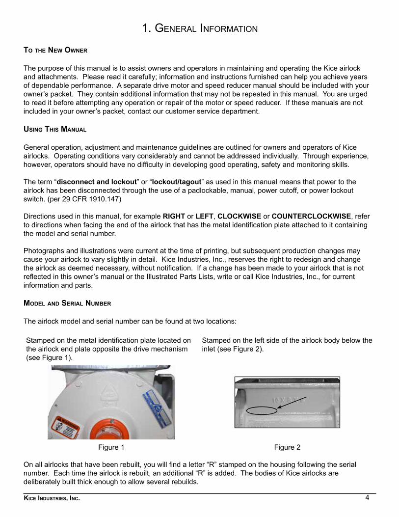
The airlock model and serial number can be found at two locations:
Stamped on the metal identification plate located on the airlock end plate opposite the drive mechanism (see Figure 1).
Stamped on the left side of the airlock body below the inlet (see Figure 2).
Figure 1 Figure 2
On all airlocks that have been rebuilt, you will find a letter “R” stamped on the housing following the serial number. Each time the airlock is rebuilt, an additional “R” is added. The bodies of Kice airlocks are deliberately built thick enough to allow several rebuilds.
5Kice industries, inc.
General information continued
for airlocK Parts and service
Use original Kice airlock replacement parts only. These parts are available from Kice Industries, Inc., only. To obtain prompt, efficient service, always provide the following information when ordering parts:
1. Correct part description and number, as given in the Illustrated Parts Lists section of this manual.2. Correct model number.3. Correct serial number.
For assistance in service or ordering parts, contact the customer service department at:
Kice Industries, Inc.5500 Mill Heights DriveWichita, KS 67219-2358Phone: 316-744-7151
Fax: 316-744-7355 IMPORTANT: Any unauthorized modification, alteration, or use of non-approved attachments or drive units voids the warranty and releases Kice Industries, Inc., from any liability arising from subsequent use of this equipment. Each type of airlock is designed to be used in specific situations, handling particular types of material. Using an airlock for any purpose other than that for which it was designed could result in personal injury, as well as product or property damage.
for motor and sPeed reducer Parts and service
The motor and speed reducer are covered by the manufacturer’s warranty. If there is a problem, check with the local supplier or service representative.
6Kice industries, inc.
2. safety PrecautIons
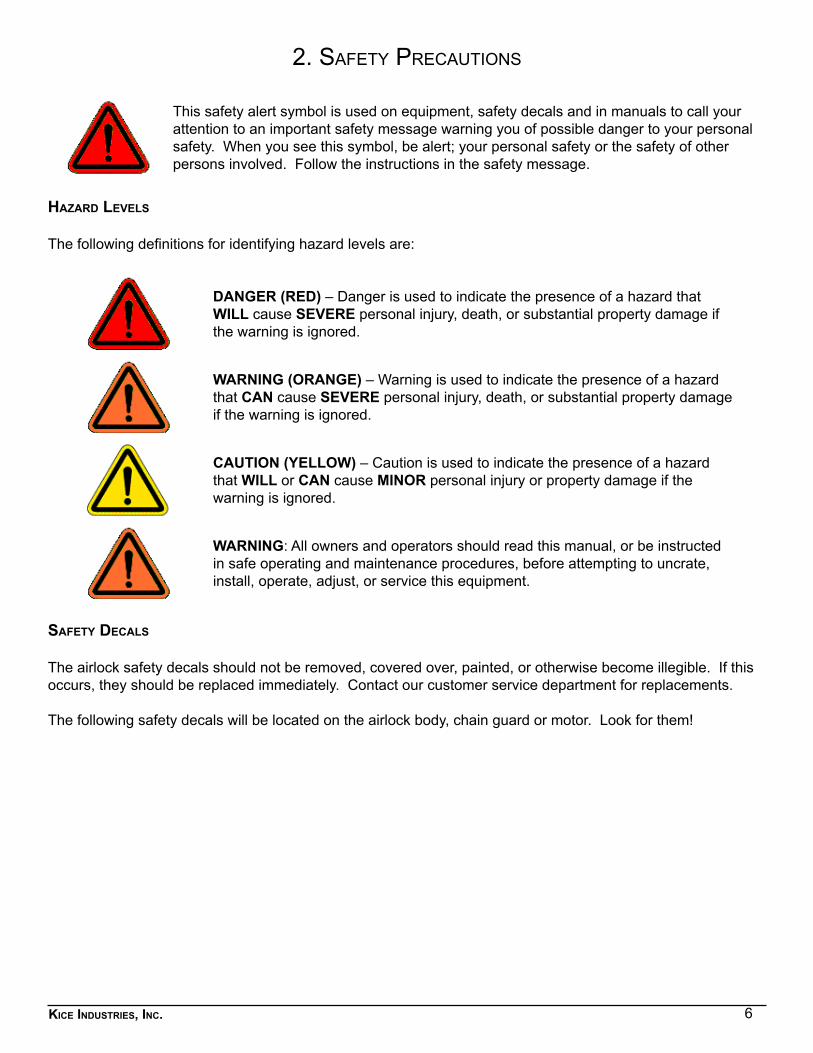
This safety alert symbol is used on equipment, safety decals and in manuals to call your attention to an important safety message warning you of possible danger to your personal safety. When you see this symbol, be alert; your personal safety or the safety of other persons involved. Follow the instructions in the safety message.
hazard levels
The following definitions for identifying hazard levels are:
DANGER (RED) – Danger is used to indicate the presence of a hazard that WILL cause SEVERE personal injury, death, or substantial property damage if the warning is ignored.
WARNING (ORANGE) – Warning is used to indicate the presence of a hazard that CAN cause SEVERE personal injury, death, or substantial property damage if the warning is ignored.
CAUTION (YELLOW) – Caution is used to indicate the presence of a hazard that WILL or CAN cause MINOR personal injury or property damage if the warning is ignored.
WARNING: All owners and operators should read this manual, or be instructed in safe operating and maintenance procedures, before attempting to uncrate, install, operate, adjust, or service this equipment.
safety decals
The airlock safety decals should not be removed, covered over, painted, or otherwise become illegible. If this occurs, they should be replaced immediately. Contact our customer service department for replacements. The following safety decals will be located on the airlock body, chain guard or motor. Look for them!
7Kice industries, inc.
safety Precautions continued
• Do not attempt to install, connect power to, operate, or service an airlock without proper instruction and until you have been thoroughly trained in its use by your employer.
• Do not attempt to open, work on, clean, service, or remove any protective cover, guard, grate, or maintenance panel from the Airlock until the POWER has been turned off and LOCKED OUT, and the airlock has come to a complete stop. Please ensure all the local, state and OSHA laws are followed.
• Do not manually override or electrically by-pass any protective device.• Do not connect power to or operate an airlock unless all moving parts are covered and all covers, guards, grates, and maintenance panels are in place
and securely fastened.• Do not abuse, overload, mistreat, or misuse an airlock or attempt to operate the equipment if it is in need of service, lubrication, maintenance, or repair.
Do not attempt to start an airlock when loaded.• Never place any part of your body under or near rotating members, or moving parts of an airlock.• The airlock may have factory supplied drives, rotating members, and moving parts which must be completely enclosed before connecting power and
before operation.• If an airlock is not equipped with a factory supplied chain guard, rotating members and moving parts must be completely enclosed before connecting
power and before operation.• Free outlet of the product must be guaranteed at all times. Otherwise, blockage and severe damage may result, or a dangerous situation may occur.• If an airlock is equipped with a maintenance panel incorporating any Protective Interlocking Limit Switch (PLS), the PLS must be interlocked with all
electrical controls so that all motors or powered devices on the unit will be de-energized if any protected cover, guard, grate, or maintenance panel is open or removed. Never attempt to manually override or electrically bypass the PLS safety device. Interlock function of the PLS must be tested and logged daily by supervisory personnel.
• Many airlocks are installed and wired to start automatically or be controlled from remote locations. Keep clear of all moving parts on industrial equipment at all times.
• An airlock must be equipped with a properly functioning Protective Interlocking Electrical Control Switch (PCS), a Padlockable Manual Power Lockout Switch, and with the other basic safety equipment listed above. On-off, interlock and padlock functions of the PCS must be tested and logged daily by supervisory personnel.
• It is the owner’s and the employer’s responsibility to adequately train the employee-operator in the proper and safe use of airlocks. Written safety programs and formal instruction are essential. All new employees must be made aware of company policies and operating rules, especially the established safety and health procedures. Refresher training of experienced employees in the potential hazards of the job is important. Up-to-date training records must be maintained at the job site.
• Special attention must be devoted to outside contractors engaged to enter and perform work on an airlock or in the workplace. Special care must be exercised to insure all such personnel are fully informed of the potential hazards and follow plant rules – with special emphasis on explosion proof electrical tools and cutting or welding in unsafe environments.
• Keep the workplace clean up and free of dirt and dust at all times. Do not attempt to work on slippery or unsafe ladders or work platforms when maintenance or repair work is being performed on an airlock.
• The operator must ensure that adequate lighting conditions are provided at the location of equipment operation.• Do not climb on ladders or work on platforms unless maximum load rating is posted. Do not exceed maximum load ratings when installing or servicing
an airlock.• Never allow any kind of metal or other foreign objects to enter an airlock. Examined raw materials should be used through the machine to ensure proper
and consistent operation.• The rotor of the airlock is built into a housing which has connection flanges for product inlet and product outlet. All airlock inlet and discharge openings
must be completely enclosed, or closed to an adequate length, to prevent human access to the rotor when the airlock is operating. They must remain enclosed until POWER IS TURNED OFF AND LOCKED OUT. Keep away from an airlock when it is running.
• Operate safely at all times. Use personal protective equipment when and where appropriate, such as hard hats, helmets, gloves, earplugs, dust masks, and eye protection devices. Keep personal protective equipment in good repair and convenient to the operator.
• Drive components must be inspected and adjusted after transportation and periodically as required by operating conditions. Check sprocket and coupling alignment and spacing, chain tension, setscrews, keys and other fasteners, bearings, shafts, gear reducers, and motors as appropriate to job conditions.
• Operator must ensure that all piping and connections are laid away from equipment access routes and steps.• High voltage and rotating parts can cause serious or fatal injury. Only qualified, trained, and experienced personnel should perform installation,
operation, and maintenance of electrical machinery. Make sure that the motor and the frame of each airlock is effectively grounded in accordance with OSHA safety and health standards, the National Electrical Code, local codes, and EN ISO 60204-1 as required for the classified area.
• Never stand under any kind of hoist or lifting mechanism, whether or not it is loaded or in operation. Never stand under or near an airlock or component when it is being lifted.
• All airlock lifting devices must be carefully inspected by qualified personnel before each use. Never use a lifting device to transport an airlock. Never use a lifting device that is damaged, deteriorated, or in any way in need of repair.
• All protective covers, guards, grates, maintenance panels, switches and warning decals must be kept in place and in good repair. Any airlock with a damaged, malfunctioning, defective, or missing protective device must be taken out of service until the protective device can be repaired or replaced.
• Any device powered by air or hydraulic pressure must be equipped with a properly functioning Padlockable Manual Pressure Lockout and Internal Pressure Relief Valve (PLV).
• Any airlock that is used in the processing of explosive materials in hazardous environments requires an evaluation on the part of the user and operator of proper and adequate airlock monitoring equipment, dust control, explosion relief venting, and electrical equipment enclosures. Do not use your airlock in hazardous environments unless it has been properly equipped for the hazard.
• It is ultimately the operator’s responsibility to implement the above listed precautions and insure proper airlock use, maintenance, and lubrication. Keep these instructions and list of warnings with your machine at all times.
• It cannot be assumed that every acceptable safety procedure is contained herein or that abnormal or unusual circumstances may not warrant or require future or additional procedures.
• Do not attempt to work on, clean or service an airlock, or open or remove any protective cover, guard, grate, or maintenance panel until the POWER has been turned off and LOCKED OUT, and the airlock has come to a complete stop. Please ensure all the local, state, and OSHA laws are followed.
• All electrical or electronic maintenance and service should be performed only by trained and authorized technicians.• Assume at all times that power is “on”. Treat all conditions as live. This practice ensures a cautious approach that may prevent an accident or injury.• Before applying power to any equipment, make certain that all personnel are clear of the machine.• Compliance with the lockout/tagout standard (29 CFR 1910.147): This standard covers the servicing and maintenance of machines and equipment in
which the unexpected energization or startup of the machines or equipment, or release of stored energy could cause injury to employees. This standard establishes minimum performance requirements for the control of such hazardous energy.
WORK SAFELY AT ALL TIMES
8Kice industries, inc.
3. PreInstallatIon PreParatIon
insPection and uncratinG after delivery
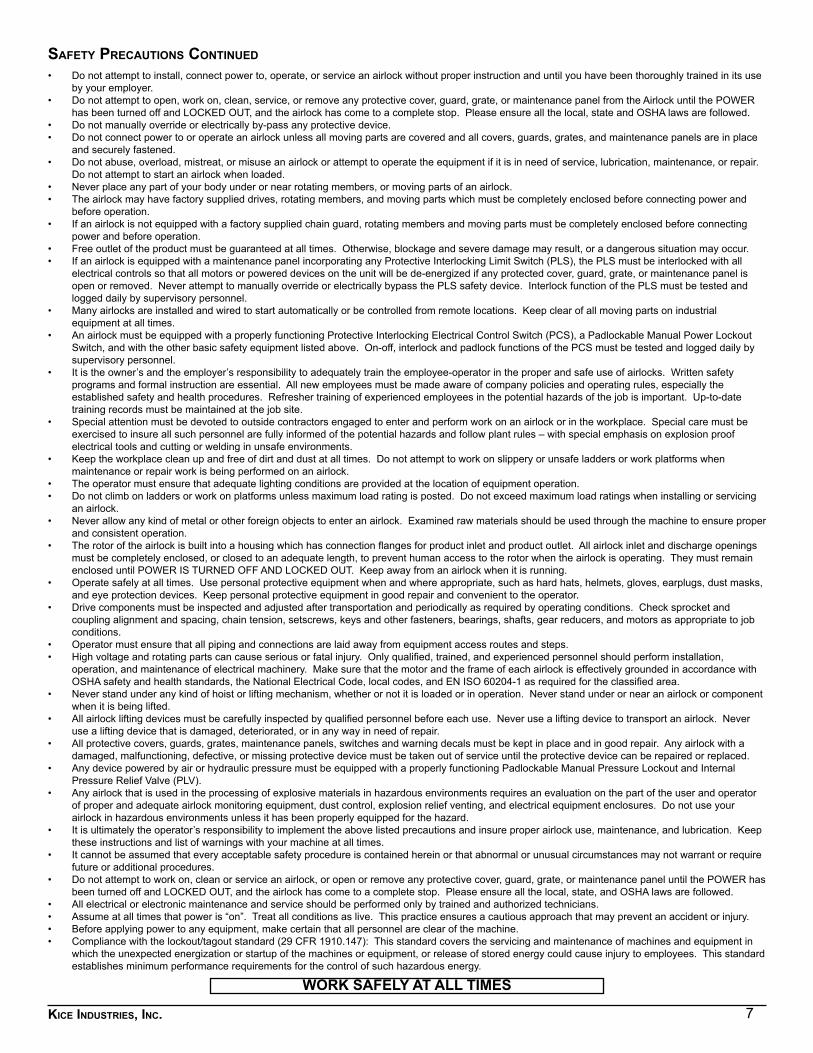
1. Inspect the airlock shaft while the airlock is still secure to the shipping pallet.a. To inspect the airlock shaft:
1. If damaged, remove the shaft cover located on the non-drive end of the shaft and the chain guard (see Figure 3).2. Check both ends of the shaft to see if they have been bent or damaged. If this is the case, file a claim with the freight company for damages and contact our customer service department.3. Replace the shaft cover and the chain guard.4. Be sure that the cover is firmly in place.
CAUTION: The shaft cover must be in place at all times. If the cover is lost in shipment or lost during airlock operation, contact our customer service department for a replacement.
Figure 3
2. Remove the airlock from the shipping palleta. Uncrate the airlock in the following manner:
1. Remove the shipping bolts securing the airlock to the shipping pallet (see Figure 3).2. Lift the airlock from the pallet using a tool truck, forklift or lifting gear with sufficient lifting capacity. The airlock should be lifted carefully by the body inlet and/or outlet flange.3. Set the airlock on a smooth level surface.4. Check all the bolts to be sure they are installed securely.
3. Inspect the rotora. To inspect the rotor:
1. Locate and read all safety decals (see Figure 3).2. Remove the protective shipping cover (see Figure 3).
CAUTION: When the protective shipping cover is removed from the airlock, do not place hands in the airlock or attempt to turn the rotor by hand. Personal injury could occur.
Safety Decals
Protective ShippingCover
Chain Guard
Shipping Bolts
Shaft Cover
9Kice industries, inc.
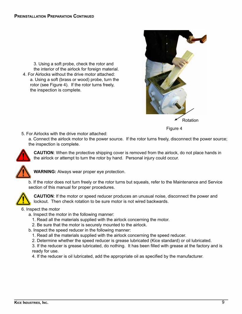
3. Using a soft probe, check the rotor and the interior of the airlock for foreign material.
4. For Airlocks without the drive motor attached:a. Using a soft (brass or wood) probe, turn the rotor (see Figure 4). If the rotor turns freely, the inspection is complete.
Rotation
Figure 45. For Airlocks with the drive motor attached:
a. Connect the airlock motor to the power source. If the rotor turns freely, disconnect the power source; the inspection is complete.
CAUTION: When the protective shipping cover is removed from the airlock, do not place hands in the airlock or attempt to turn the rotor by hand. Personal injury could occur.
WARNING: Always wear proper eye protection.
b. If the rotor does not turn freely or the rotor turns but squeals, refer to the Maintenance and Service section of this manual for proper procedures.
CAUTION: If the motor or speed reducer produces an unusual noise, disconnect the power and lockout. Then check rotation to be sure motor is not wired backwards.
6. Inspect the motora. Inspect the motor in the following manner:
1. Read all the materials supplied with the airlock concerning the motor.2. Be sure that the motor is securely mounted to the airlock.
b. Inspect the speed reducer in the following manner:1. Read all the materials supplied with the airlock concerning the speed reducer.2. Determine whether the speed reducer is grease lubricated (Kice standard) or oil lubricated.3. If the reducer is grease lubricated, do nothing. It has been filled with grease at the factory and is ready for use.4. If the reducer is oil lubricated, add the appropriate oil as specified by the manufacturer.
Preinstallation PreParation continued
10Kice industries, inc.
4. InstallatIon
CAUTION: Use proper equipment when lifting or moving the airlock. Make sure all persons and obstructions are clear from path and installation area.
Installation of the Rotary Airlock Valve (which may include the motor), is completed by the operator. When installing the equipment, please make sure that the moving parts inside the equipment are not accessible. This also fulfils EN ISO 13857-1 where required.
After uncrating and inspection has been completed, install the airlock in the following manner:1. Move the airlock to the installation area using proper equipment. The airlock should be lifted carefully by
the body inlet and/or outlet flange.2. Check the mounting surfaces of the airlock and any adjoining system components. They should be free
of foreign materials. 3. Mount the airlock in place.
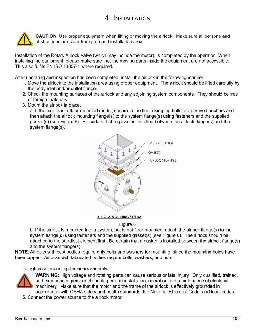
a. If the airlock is a floor-mounted model, secure to the floor using lag bolts or approved anchors and then attach the airlock mounting flange(s) to the system flange(s) using fasteners and the supplied gasket(s) (see Figure 6). Be certain that a gasket is installed between the airlock flange(s) and the system flange(s).
SYSTEM FLANGE
GASKET
AIRLOCK FLANGE
AIRLOCK MOUNTING SYSTEM
Figure 6b. If the airlock is mounted into a system, but is not floor mounted, attach the airlock flange(s) to the system flange(s) using fasteners and the supplied gasket(s) (see Figure 6). The airlock should be attached to the sturdiest element first. Be certain that a gasket is installed between the airlock flange(s) and the system flange(s).
NOTE: Airlocks with cast bodies require only bolts and washers for mounting, since the mounting holes have been tapped. Airlocks with fabricated bodies require bolts, washers, and nuts.
4. Tighten all mounting fasteners securely.WARNING: High voltage and rotating parts can cause serious or fatal injury. Only qualified, trained, and experienced personnel should perform installation, operation and maintenance of electrical machinery. Make sure that the motor and the frame of the airlock is effectively grounded in accordance with OSHA safety and health standards, the National Electrical Code, and local codes.
5. Connect the power source to the airlock motor.
11Kice industries, inc.
installation continued
6. Test run the airlock. If any unusual noises occur, disconnect and lockout the power source, and check the wiring hook-ups to the motor. If the airlock rotor was turning in the wrong direction, reverse the wiring hook-ups to the motor, and retest.
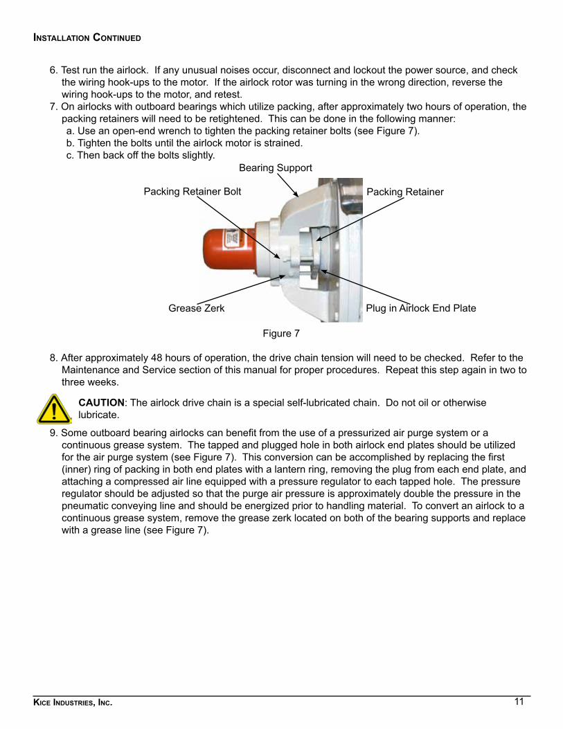
7. On airlocks with outboard bearings which utilize packing, after approximately two hours of operation, the packing retainers will need to be retightened. This can be done in the following manner:a. Use an open-end wrench to tighten the packing retainer bolts (see Figure 7).b. Tighten the bolts until the airlock motor is strained.c. Then back off the bolts slightly.
Figure 7
8. After approximately 48 hours of operation, the drive chain tension will need to be checked. Refer to the Maintenance and Service section of this manual for proper procedures. Repeat this step again in two to three weeks.
CAUTION: The airlock drive chain is a special self-lubricated chain. Do not oil or otherwise lubricate.
9. Some outboard bearing airlocks can benefit from the use of a pressurized air purge system or a continuous grease system. The tapped and plugged hole in both airlock end plates should be utilized for the air purge system (see Figure 7). This conversion can be accomplished by replacing the first (inner) ring of packing in both end plates with a lantern ring, removing the plug from each end plate, and attaching a compressed air line equipped with a pressure regulator to each tapped hole. The pressure regulator should be adjusted so that the purge air pressure is approximately double the pressure in the pneumatic conveying line and should be energized prior to handling material. To convert an airlock to a continuous grease system, remove the grease zerk located on both of the bearing supports and replace with a grease line (see Figure 7).
Packing Retainer Bolt Packing Retainer
Bearing Support
Grease Zerk Plug in Airlock End Plate
12Kice industries, inc.
5. maIntenance and servIce
The key to long and trouble-free airlock operation is good maintenance practices. Periodically inspect the rotor for damage caused by foreign material and for proper placement within the airlock body. Inspect the bearings and the drive chain for excessive wear. Finally, service the motor and the speed reducer as specified by the manufacturer. The majority of operating problems that occur with an airlock can be traced to improper adjustments and delayed, or neglected maintenance. A consistently applied maintenance program will prevent many problems. A thorough understanding of the system is required if the operating problems are to be corrected satisfactorily. A good rule to follow when troubleshooting a problem is to never make more than one adjustment at a time, thereby isolating the problem by a process of elimination. The cause of a problem is usually simple and is easy to pinpoint if you systematically check each system and function.
motor and sPeed reducer service
To obtain parts or service for the airlock motor or speed reducer, contact the local dealer or service representative for the particular make of motor or speed reducer used on the airlock. Not all airlocks use the same make.
1. Motor: The motor manufacturer has supplied you with safety, service, and repair information. If you have difficulty obtaining service or repair parts, contact our customer service department.
2. Speed Reducer: The speed reducer manufacturer has supplied you with safety, service, and repair information. If you have difficulty obtaining service or repair parts, contact our customer service department.
WARNING: Never place hands or fingers in an airlock, unless it has been disconnected and locked out, and a wooden block has been placed in the airlock to prevent the rotor from turning.
rotor
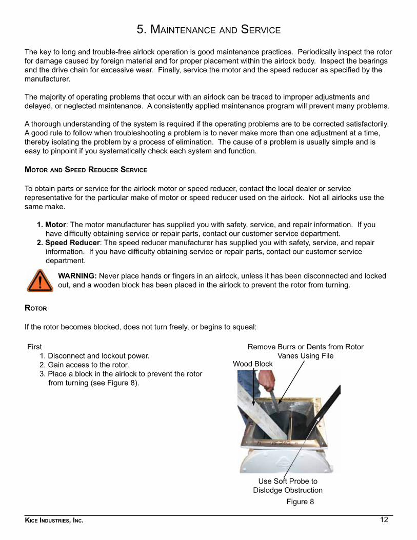
If the rotor becomes blocked, does not turn freely, or begins to squeal:
First1. Disconnect and lockout power.2. Gain access to the rotor.3. Place a block in the airlock to prevent the rotor
from turning (see Figure 8).
Wood Block
Use Soft Probe to Dislodge Obstruction
Remove Burrs or Dents from Rotor Vanes Using File
Figure 8
13Kice industries, inc.
maintenance and service continued
Then, for blockage in rotor4. Using a probe, dislodge the obstruction from the rotor and discard (See Figure 8).5. Remove the block and, using the probe, turn the rotor to inspect for additional foreign material.
For rotor damage – rotor does not turn freely6. Locate the rotor damage, such as burrs or dents in the rotor vanes.7. Remove any burrs or dents using a file (see Figure 8).
CAUTION: When removing burrs or dents, remove only the damage. Proper clearance (.004” ± .001” in smaller airlocks and .005” ± .001” in larger airlocks) must be maintained between the rotor vanes and the airlock body.
airlocK valves With inBoard BearinGs
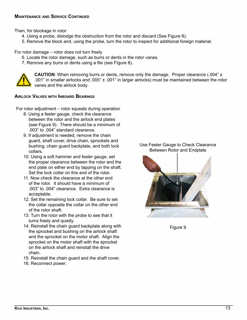
For rotor adjustment – rotor squeals during operation8. Using a feeler gauge, check the clearance
between the rotor and the airlock end plates (see Figure 9). There should be a minimum of .003” to .004” standard clearance.
9. If adjustment is needed, remove the chain guard, shaft cover, drive chain, sprockets and bushing, chain guard backplate, and both lock collars.
10. Using a soft hammer and feeler gauge, set the proper clearance between the rotor and the end plate on either end by tapping on the shaft. Set the lock collar on this end of the rotor.
11. Now check the clearance at the other end of the rotor. It should have a minimum of .003” to .004” clearance. Extra clearance is acceptable.
12. Set the remaining lock collar. Be sure to set the collar opposite the collar on the other end of the rotor shaft.
13. Turn the rotor with the probe to see that it turns freely and quietly.
14. Reinstall the chain guard backplate along with the sprocket and bushing on the airlock shaft and the sprocket on the motor shaft. Align the sprocket on the motor shaft with the sprocket on the airlock shaft and reinstall the drive chain.
15. Reinstall the chain guard and the shaft cover. 16. Reconnect power.
Use Feeler Gauge to Check Clearance Between Rotor and Endplate
Figure 9
14Kice industries, inc.
maintenance and service continued
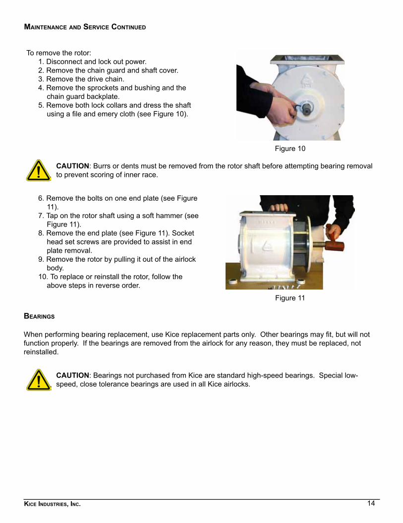
To remove the rotor:1. Disconnect and lock out power.2. Remove the chain guard and shaft cover.3. Remove the drive chain.4. Remove the sprockets and bushing and the
chain guard backplate.5. Remove both lock collars and dress the shaft
using a file and emery cloth (see Figure 10).
Figure 10
CAUTION: Burrs or dents must be removed from the rotor shaft before attempting bearing removal to prevent scoring of inner race.
6. Remove the bolts on one end plate (see Figure 11).
7. Tap on the rotor shaft using a soft hammer (see Figure 11).
8. Remove the end plate (see Figure 11). Socket head set screws are provided to assist in end plate removal.
9. Remove the rotor by pulling it out of the airlock body.
10. To replace or reinstall the rotor, follow the above steps in reverse order.
Figure 11
BearinGs
When performing bearing replacement, use Kice replacement parts only. Other bearings may fit, but will not function properly. If the bearings are removed from the airlock for any reason, they must be replaced, not reinstalled.
CAUTION: Bearings not purchased from Kice are standard high-speed bearings. Special low-speed, close tolerance bearings are used in all Kice airlocks.
15Kice industries, inc.
maintenance and service continued
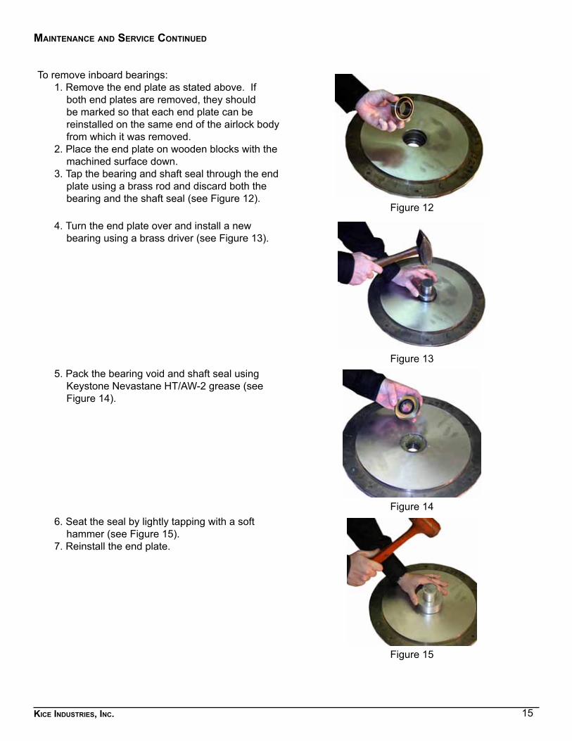
To remove inboard bearings:1. Remove the end plate as stated above. If
both end plates are removed, they should be marked so that each end plate can be reinstalled on the same end of the airlock body from which it was removed.
2. Place the end plate on wooden blocks with the machined surface down.
3. Tap the bearing and shaft seal through the end plate using a brass rod and discard both the bearing and the shaft seal (see Figure 12).
Figure 12
4. Turn the end plate over and install a new bearing using a brass driver (see Figure 13).
Figure 135. Pack the bearing void and shaft seal using
Keystone Nevastane HT/AW-2 grease (see Figure 14).
Figure 146. Seat the seal by lightly tapping with a soft
hammer (see Figure 15).7. Reinstall the end plate.
Figure 15
16Kice industries, inc.
maintenance and service continued
outBoard BearinG airlocK valves (With timKen BearinGs)
General
Kice airlock valves can be disassembled and reassembled in the field using tools and abilities found in all maintenance departments. Following are suggested step-by-step procedures.
adJustinG airlocK clearance
NOTE: Letters shown in parentheses ( ) correspond to item designations in the Itemized Parts List.
1. Use standard “Lockout and Tagout Procedures” on the electric motor BEFORE STARTING ANY maintenance.
NOTE: The serial number is stamped into the body on the drive end side opposite the motor and speed reducer.
2. Using a feeler gauge, check the clearance between the rotor and the end plates. There should be a minimum clearance of 0.003” to 0.004”. Clearances may vary depending on operating temperature and valve size.
3. Remove the chain guard, the drive chain, the sprocket and the bushing on the airlock shaft, the sprocket on the reducer shaft, the chain guard backplate, and the shaft cover.
4. Remove both end caps (T) from the bearing supports.5. Clean the grease from the bearing assemblies.6. Straighten the lock washer (P) tab from the slot on both adjusting nuts (R).7. Using a spanner wrench, loosen one adjusting nut while tightening the other. To increase the internal
clearance between the rotor and the near side end plate, loosen (CCW) the adjusting nut on the near side while tightening the adjusting nut on the far side. To decrease the internal clearance between the rotor and the near side end plate, perform the operation in reverse.
8. When the desired internal clearance is achieved, bend down the lock washer tabs to lock the nuts in place.
9. Reinstall the end caps onto the bearing supports. After packing void with fresh grease.10. Reinstall the chain guard backplate, the sprocket and bushing on the airlock shaft, the sprocket on the
reducer shaft, the drive chain, the chain guard, and the shaft cover.
rotor removal from Body
1. Use standard “Lockout and Tagout Procedures” on the electric motor BEFORE STARTING ANY maintenance.
2. Remove the shaft cover, the chain guard, the drive chain, the sprocket and the bushing on the airlock shaft, the sprocket on the reducer shaft, and the chain guard backplate.
3. Remove both end caps (T) from the bearing supports.4. Clean the grease from the bearing assemblies.5. Straighten the lock washer (P) tab from the slot on both adjusting nuts (R).6. Using a spanner wrench, loosen both adjusting nuts and remove the nuts and lock washer from the
shaft.7. Pick the most accessible end plate (C) and remove all the bolts holding the end plate to the body.8. Loosen the packing gland retainer by turning the three square head setscrews (H), located on the
bearing support, 1 to 1 ½ turns.9. Pull the end plate off by tapping the opposite rotor shaft (B) with a soft mallet. The bearing (M) will come
out of the bearing cup (L).10. When the step along the circumference of the end plate is out of the body, the end plate may be
17Kice industries, inc.
maintenance and service continued
removed from the shaft.11. There is a spring inside the inner lip seal (J) to keep the seal tight against the shaft. When the end
plate is removed, the threads on the rotor shaft may cause the spring to come out of the seal. If so, reinstall the spring prior to reassembly.
12. The rotor is now partially out of the body. Completely remove the rotor from the body.13. Check the spring inside the inner lip seal of the opposite shaft (reference step 11).14. Match mark one end of the rotor to one end plate, so that the rotor can be reassembled in the same
direction as originally built.15. Now that the rotor is removed from the body, care should be taken to avoid damaging the rotor tips and
ends, shaft threads, and bearing cone (M).16. If both plates are removed, they should be match marked to the side of the body, so that they can be
reassemble to the original position.17. Make necessary repairs and reassemble per the following instructions. Care should be taken to install
the rotor back to the original direction.
reassemBly
1. Check the lip seal on the inside of both bearing supports. If the seals (J) need to be replaced, they need to be changed before the end plates are installed on the body.
2. To change the seal, the spacer, bearing cup and the bearing (K, L & M) need to be removed before the seal (J) can be replaced.
3. Reinstall the parts per drawing (RAV-5001 or RAV-5002). CARE should be taken to install the components in the proper order.
4. Pick the most accessible end plate (C) and install and tighten all the bolts holding the end plate to the body.
5. Reinstall the rotor in the body. As the rotor is installed, make sure that the packing retainer (G) is in place before sliding the shaft through the bearing. Care should be taken to install the rotor back to the original orientation.
6. Reinstall the other end plate on the body. As the end plate is installed, make sure that the packing retainer (G) is in place before sliding the shaft through the bearing.
7. Install and tighten all the bolts holding the end plate to the body.8. Reinstall the lock washer and adjusting nuts (P & R) on both sides of the airlock valve, but do not tighten.9. Using a feeler gauge and a spanner wrench, tighten one adjusting nut while loosening the other until
the rotor moves to the proper clearance. Reference step 7 in the section entitled Adjusting Airlock Clearance.
10. When the desired internal clearance is achieved, bend the lock washer tabs down to lock the nuts in place.
11. Using a grease gun, pack the bearings with grease. When grease starts to come through the rollers, reinstall both end caps (T) onto the bearing supports.
12. Reinstall the chain guard backplate, the sprocket and bushing on the airlock shaft, the sprocket on the reducer shaft, the drive chain, the chain guard, and the shaft cover.
NOTE:TIMKEN BEARING CUP 394A (item L)
MUST BE REPLACED WITH EXACT SAME PART NUMBER!!!NO SUBSTITUTIONS!!!
18Kice industries, inc.
maintenance and service continued
drive chain
After approximately 48 hours of initial operation, check the drive chain tension. Check it again in 2 to 3 weeks. The following procedures should be followed if the drive chain needs adjusting or replacing.
CAUTION: The airlock drive chain is a special self-lubricated chain. Do not oil or otherwise lubricate.
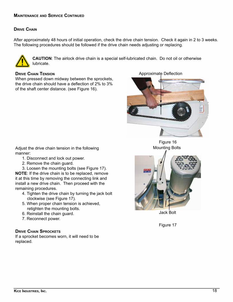
drive chain tensionWhen pressed down midway between the sprockets, the drive chain should have a deflection of 2% to 3% of the shaft center distance. (see Figure 16).
Approximate Deflection
Figure 16Adjust the drive chain tension in the following manner:
1. Disconnect and lock out power.2. Remove the chain guard.3. Loosen the mounting bolts (see Figure 17).
NOTE: If the drive chain is to be replaced, remove it at this time by removing the connecting link and install a new drive chain. Then proceed with the remaining procedures.
4. Tighten the drive chain by turning the jack bolt clockwise (see Figure 17).
5. When proper chain tension is achieved, retighten the mounting bolts.
6. Reinstall the chain guard.7. Reconnect power.
Figure 17drive chain sProcKetsIf a sprocket becomes worn, it will need to be replaced.
Jack Bolt
Mounting Bolts
19Kice industries, inc.
maintenance and service continued
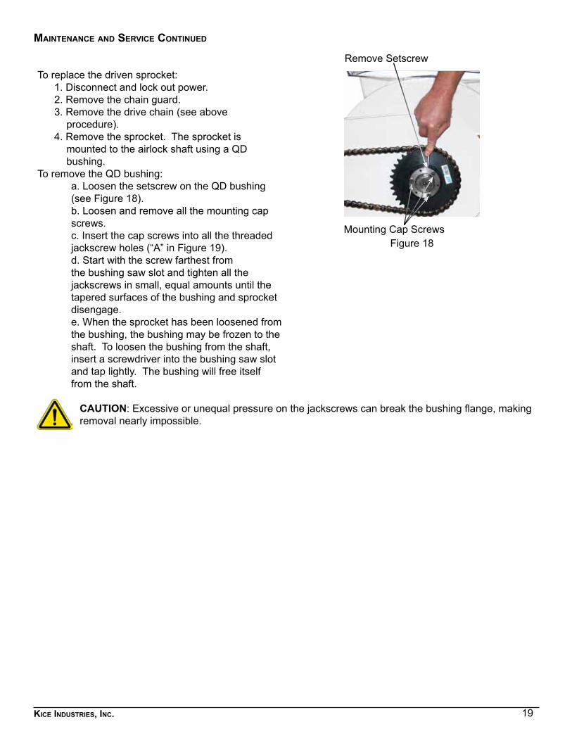
To replace the driven sprocket:1. Disconnect and lock out power.2. Remove the chain guard.3. Remove the drive chain (see above
procedure).4. Remove the sprocket. The sprocket is
mounted to the airlock shaft using a QD bushing.
To remove the QD bushing:a. Loosen the setscrew on the QD bushing (see Figure 18).b. Loosen and remove all the mounting cap screws.c. Insert the cap screws into all the threaded jackscrew holes (“A” in Figure 19).d. Start with the screw farthest from the bushing saw slot and tighten all the jackscrews in small, equal amounts until the tapered surfaces of the bushing and sprocket disengage.e. When the sprocket has been loosened from the bushing, the bushing may be frozen to the shaft. To loosen the bushing from the shaft, insert a screwdriver into the bushing saw slot and tap lightly. The bushing will free itself from the shaft.
Figure 18
CAUTION: Excessive or unequal pressure on the jackscrews can break the bushing flange, making removal nearly impossible.
Remove Setscrew
Mounting Cap Screws
20Kice industries, inc.
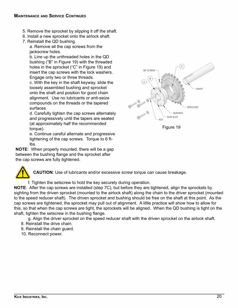
5. Remove the sprocket by slipping it off the shaft.6. Install a new sprocket onto the airlock shaft.7. Reinstall the QD bushing.
a. Remove all the cap screws from the jackscrew holes.b. Line up the unthreaded holes in the QD bushing (“B” in Figure 19) with the threaded holes in the sprocket (“C” in Figure 19) and insert the cap screws with the lock washers. Engage only two or three threads.c. With the key in the shaft keyway, slide the loosely assembled bushing and sprocket onto the shaft and position for good chain alignment. Use no lubricants or anti-seize compounds on the threads or the tapered surfaces.d. Carefully tighten the cap screws alternately and progressively until the tapers are seated (at approximately half the recommended torque). e. Continue careful alternate and progressive tightening of the cap screws. Torque to 6 ft-lbs.
NOTE: When properly mounted, there will be a gap between the bushing flange and the sprocket after the cap screws are fully tightened.
SPROCKET
BUSHING
KEY
SHAFT
SPROCKET & BUSHING ASSEMBLY
AB
C
SET SCREW
SAW SLOT
Figure 19
CAUTION: Use of lubricants and/or excessive screw torque can cause breakage.
f. Tighten the setscrew to hold the key securely during operation.NOTE: After the cap screws are installed (step 7C), but before they are tightened, align the sprockets by sighting from the driven sprocket (mounted to the airlock shaft) along the chain to the driver sprocket (mounted to the speed reducer shaft). The driven sprocket and bushing should be free on the shaft at this point. As the cap screws are tightened, the sprocket may pull out of alignment. A little practice will show how to allow for this, so that when the cap screws are tight, the sprockets will be aligned. When the QD bushing is tight on the shaft, tighten the setscrew in the bushing flange.
g. Align the driver sprocket on the speed reducer shaft with the driven sprocket on the airlock shaft.8. Reinstall the drive chain.9. Reinstall the chain guard.10. Reconnect power.
maintenance and service continued
21Kice industries, inc.
maintenance and service continued
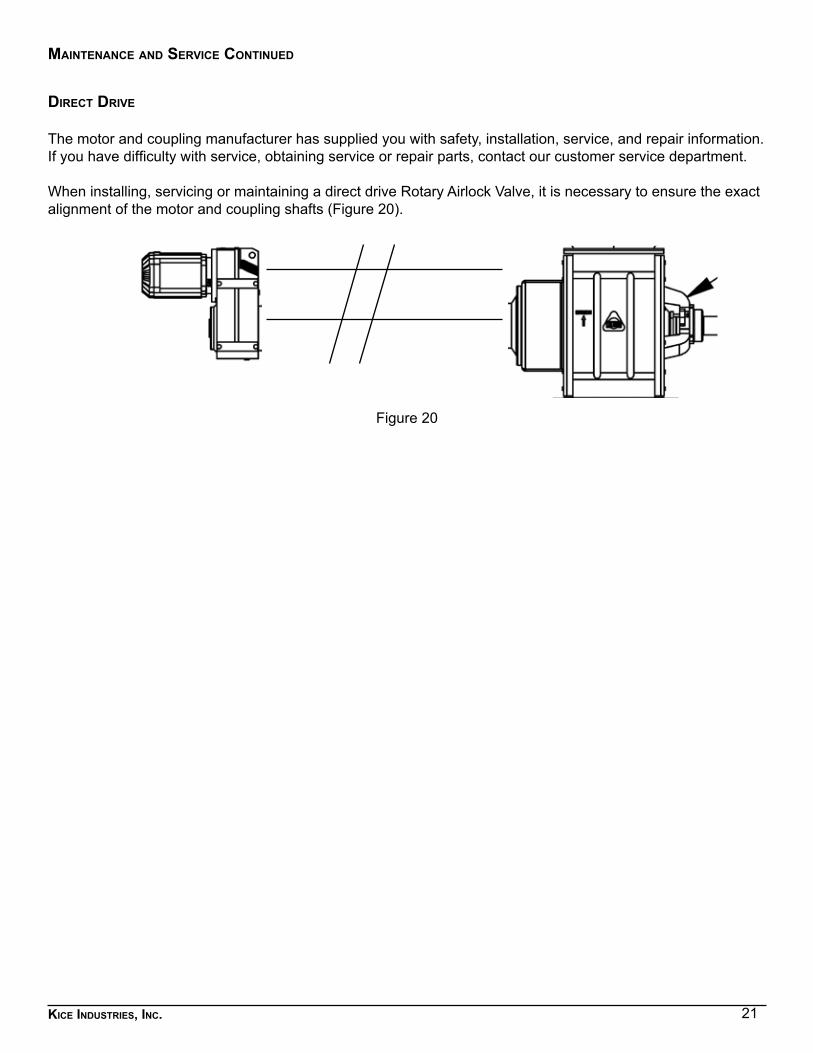
direct drive
The motor and coupling manufacturer has supplied you with safety, installation, service, and repair information. If you have difficulty with service, obtaining service or repair parts, contact our customer service department.
When installing, servicing or maintaining a direct drive Rotary Airlock Valve, it is necessary to ensure the exact alignment of the motor and coupling shafts (Figure 20).
Figure 20
22Kice industries, inc.
6. sPecIal ateX InformatIon
The outside of the Rotary Airlock Valve is intended for use in areas in which explosive atmospheres caused by air/dusts mixtures are unlikely to occur or, if they do occur, are likely to do so only infrequently and for a short period only.
The inside of the Rotary Airlock Valve is intended for use withstanding an atmosphere where dust clouds are likely to be present occasionally during normal operation.When installing an electric motor and other electric or non-electric equipment on the rotary airlock valve, be sure that all those components are suitable for being operated in zone 22, meaning they must fulfil the ATEX-requirements for Group II category 3D equipment.
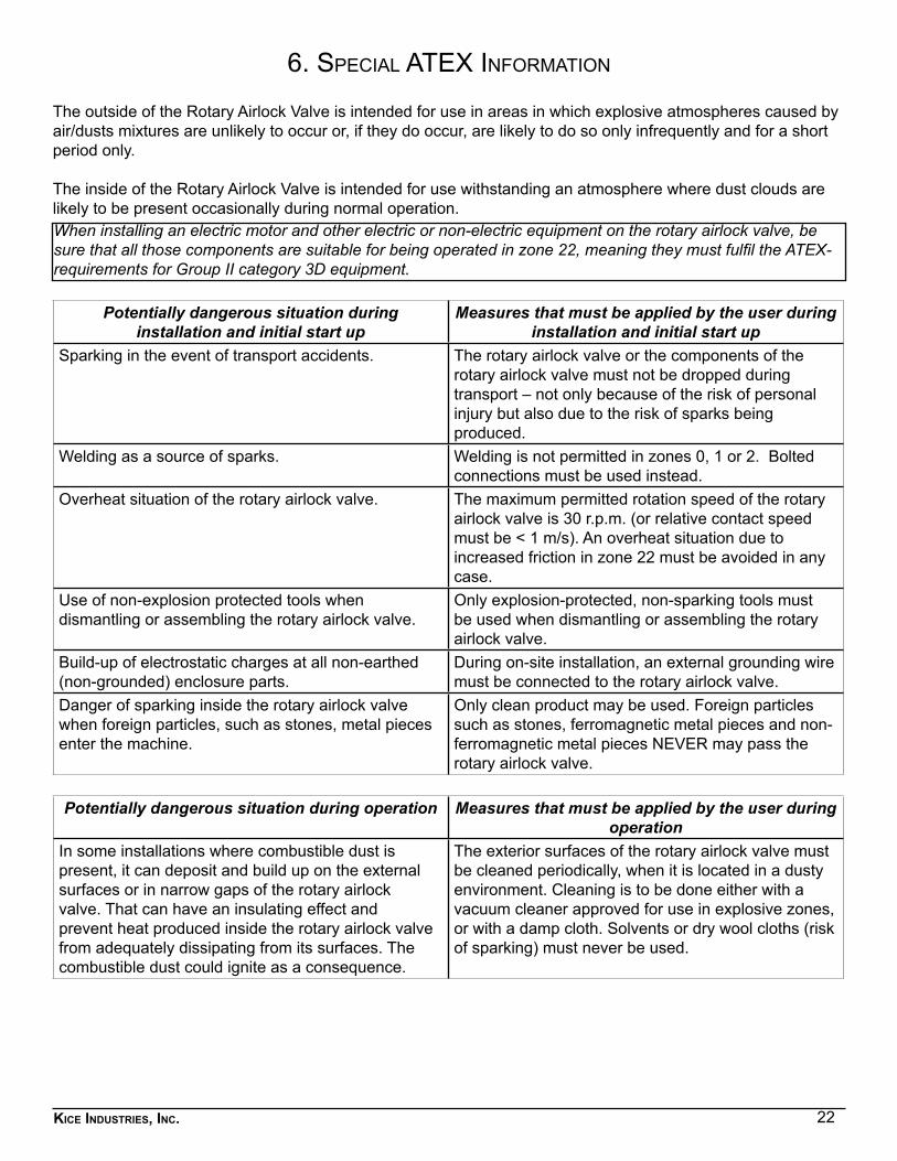
Potentially dangerous situation during installation and initial start up
Measures that must be applied by the user during installation and initial start up
Sparking in the event of transport accidents. The rotary airlock valve or the components of the rotary airlock valve must not be dropped during transport – not only because of the risk of personal injury but also due to the risk of sparks being produced.
Welding as a source of sparks. Welding is not permitted in zones 0, 1 or 2. Bolted connections must be used instead.
Overheat situation of the rotary airlock valve. The maximum permitted rotation speed of the rotary airlock valve is 30 r.p.m. (or relative contact speed must be < 1 m/s). An overheat situation due to increased friction in zone 22 must be avoided in any case.
Use of non-explosion protected tools when dismantling or assembling the rotary airlock valve.
Only explosion-protected, non-sparking tools must be used when dismantling or assembling the rotary airlock valve.
Build-up of electrostatic charges at all non-earthed (non-grounded) enclosure parts.
During on-site installation, an external grounding wire must be connected to the rotary airlock valve.
Danger of sparking inside the rotary airlock valve when foreign particles, such as stones, metal pieces enter the machine.
Only clean product may be used. Foreign particles such as stones, ferromagnetic metal pieces and non-ferromagnetic metal pieces NEVER may pass the rotary airlock valve.
Potentially dangerous situation during operation Measures that must be applied by the user during operation
In some installations where combustible dust is present, it can deposit and build up on the external surfaces or in narrow gaps of the rotary airlock valve. That can have an insulating effect and prevent heat produced inside the rotary airlock valve from adequately dissipating from its surfaces. The combustible dust could ignite as a consequence.
The exterior surfaces of the rotary airlock valve must be cleaned periodically, when it is located in a dusty environment. Cleaning is to be done either with a vacuum cleaner approved for use in explosive zones, or with a damp cloth. Solvents or dry wool cloths (risk of sparking) must never be used.
23Kice industries, inc.
sPecial ateX infomration continued
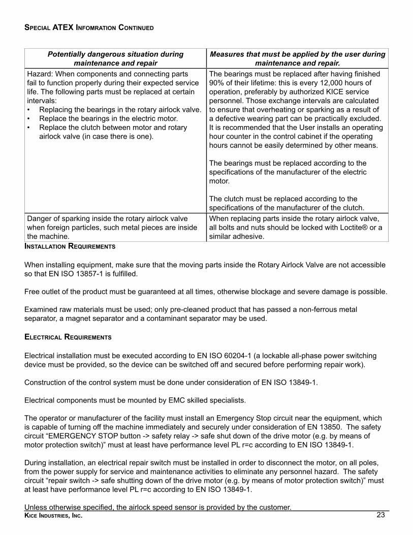
Potentially dangerous situation during maintenance and repair
Measures that must be applied by the user during maintenance and repair.
Hazard: When components and connecting parts fail to function properly during their expected service life. The following parts must be replaced at certain intervals:• Replacing the bearings in the rotary airlock valve.• Replace the bearings in the electric motor.• Replace the clutch between motor and rotary
airlock valve (in case there is one).
The bearings must be replaced after having finished 90% of their lifetime: this is every 12,000 hours of operation, preferably by authorized KICE service personnel. Those exchange intervals are calculated to ensure that overheating or sparking as a result of a defective wearing part can be practically excluded. It is recommended that the User installs an operating hour counter in the control cabinet if the operating hours cannot be easily determined by other means.
The bearings must be replaced according to the specifications of the manufacturer of the electric motor.
The clutch must be replaced according to the specifications of the manufacturer of the clutch.
Danger of sparking inside the rotary airlock valve when foreign particles, such metal pieces are inside the machine.
When replacing parts inside the rotary airlock valve, all bolts and nuts should be locked with Loctite® or a similar adhesive.
installation requirements
When installing equipment, make sure that the moving parts inside the Rotary Airlock Valve are not accessible so that EN ISO 13857-1 is fulfilled.
Free outlet of the product must be guaranteed at all times, otherwise blockage and severe damage is possible.
Examined raw materials must be used; only pre-cleaned product that has passed a non-ferrous metal separator, a magnet separator and a contaminant separator may be used.
electrical requirements
Electrical installation must be executed according to EN ISO 60204-1 (a lockable all-phase power switching device must be provided, so the device can be switched off and secured before performing repair work).
Construction of the control system must be done under consideration of EN ISO 13849-1.
Electrical components must be mounted by EMC skilled specialists.
The operator or manufacturer of the facility must install an Emergency Stop circuit near the equipment, which is capable of turning off the machine immediately and securely under consideration of EN 13850. The safety circuit “EMERGENCY STOP button -> safety relay -> safe shut down of the drive motor (e.g. by means of motor protection switch)” must at least have performance level PL r=c according to EN ISO 13849-1.
During installation, an electrical repair switch must be installed in order to disconnect the motor, on all poles, from the power supply for service and maintenance activities to eliminate any personnel hazard. The safety circuit “repair switch -> safe shutting down of the drive motor (e.g. by means of motor protection switch)” must at least have performance level PL r=c according to EN ISO 13849-1.
Unless otherwise specified, the airlock speed sensor is provided by the customer.
24Kice industries, inc.
sPecial ateX infomration continued
GroundinG (earthinG) of conductinG Parts
It is normally sufficient to separately ground the static parts of the airlock when installed. If necessary, shaft grounding systems may be used. (This is to avoid any electrostatic charge and potentially dangerous situation).
Paint
It is ensured via an internal instruction and after coordination with the painter that maximum thickness of paint (i.e. varnish) inside and outside does not exceed 0.2mm.
marKinGs
The nameplate shall be fixed permanently to the airlock and indicate: Name and address of the manufacturer, date of construction, designation or type of airlock, serial or identification number, technical file number, the CE mark and classification markings.
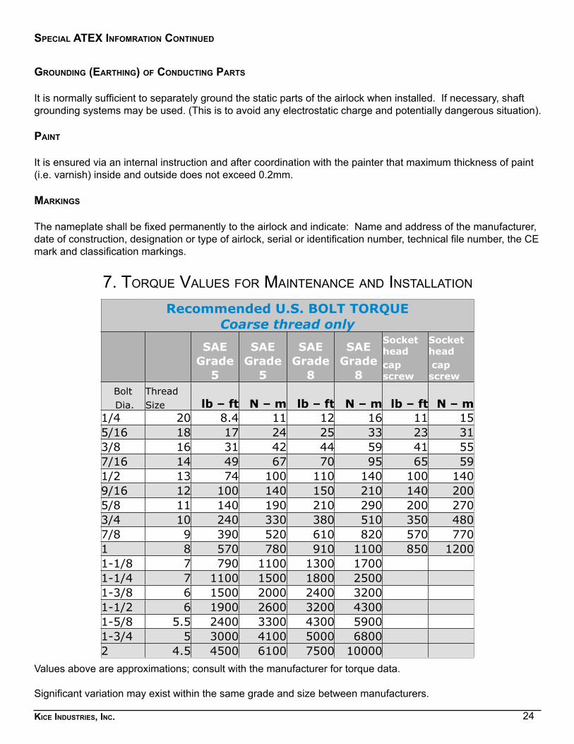
7. torque values for maIntenance and InstallatIon
Values above are approximations; consult with the manufacturer for torque data.
Significant variation may exist within the same grade and size between manufacturers.
Recommended U.S. BOLT TORQUECoarse thread only
SAE Grade
5
SAE Grade
5
SAE Grade
8
SAE Grade
8
Socket head
Socket head
cap screw
cap screw
Bolt Threadlb – ft N – m lb – ft N – m lb – ft N – m Dia. Size
1/4 20 8.4 11 12 16 11 155/16 18 17 24 25 33 23 313/8 16 31 42 44 59 41 557/16 14 49 67 70 95 65 591/2 13 74 100 110 140 100 1409/16 12 100 140 150 210 140 2005/8 11 140 190 210 290 200 2703/4 10 240 330 380 510 350 4807/8 9 390 520 610 820 570 7701 8 570 780 910 1100 850 12001-1/8 7 790 1100 1300 1700 1-1/4 7 1100 1500 1800 2500 1-3/8 6 1500 2000 2400 3200 1-1/2 6 1900 2600 3200 4300 1-5/8 5.5 2400 3300 4300 5900 1-3/4 5 3000 4100 5000 6800 2 4.5 4500 6100 7500 10000
25Kice industries, inc.
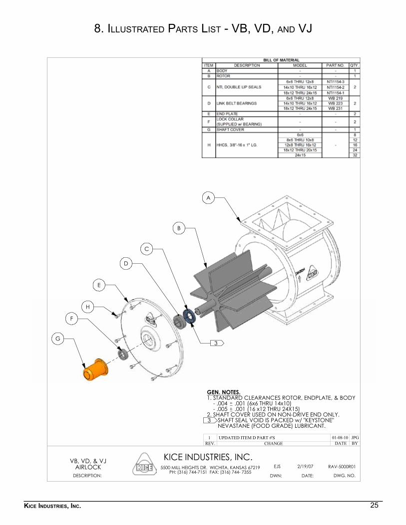
8. Illustrated Parts lIst - vb, vd, and vJ
A
B
C
D
E
F
G
H
3
DWG. NO.
KICE INDUSTRIES, INC.
DATE:DWN:
5500 MILL HEIGHTS DR. WICHITA, KANSAS 67219PH: (316) 744-7151 FAX: (316) 744- 7355
2/19/07EJS RAV-5000R01
DESCRIPTION:
VB, VD, & VJAIRLOCK
GEN. NOTES.1. STANDARD CLEARANCES ROTOR, ENDPLATE, & BODY - .004 .001 (6x6 THRU 14x10) - .005 .001 (16 x12 THRU 24X15)2. SHAFT COVER USED ON NON-DRIVE END ONLY. SHAFT SEAL VOID IS PACKED w/ "KEYSTONE" NEVASTANE (FOOD GRADE) LUBRICANT.3
JPG01-08-10UPDATED ITEM D PART #'S1REV. CHANGE BYDATE
26Kice industries, inc.
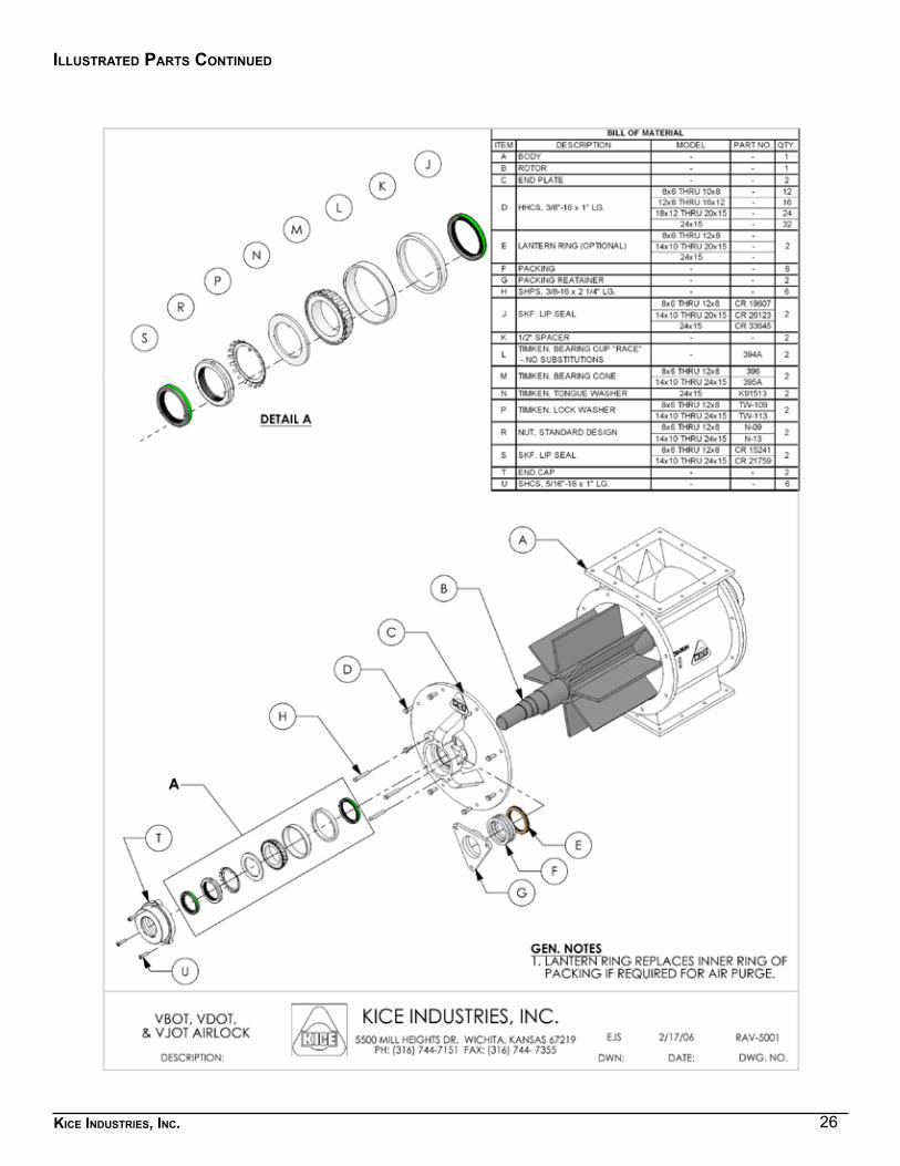
illustrated Parts continued
27Kice industries, inc.
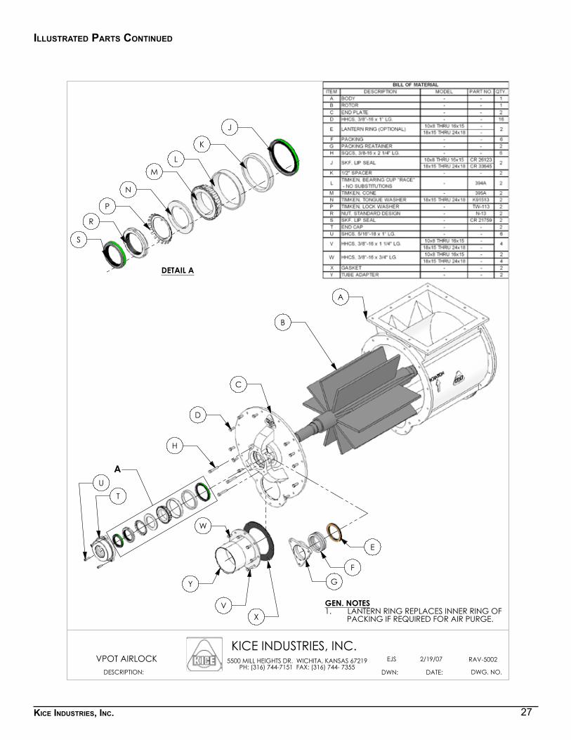
illustrated Parts continued
A
A
B
C
D
E
F
G
H
TU
V
W
X
Y
DETAIL A
J
K
LM
N
P
R
S
DWG. NO.
KICE INDUSTRIES, INC.
DATE:DWN:
5500 MILL HEIGHTS DR. WICHITA, KANSAS 67219PH: (316) 744-7151 FAX: (316) 744- 7355
2/19/07EJS RAV-5002
DESCRIPTION:
VPOT AIRLOCK
GEN. NOTESLANTERN RING REPLACES INNER RING OF 1.
PACKING IF REQUIRED FOR AIR PURGE.

28Kice industries, inc.© 2013 Kice Industries, Inc.
5500 N. Mill Heights Dr.Wichita, KS 67219-2358(P) 316.744.7151(F) [email protected]
kice.com