rotary cutters - john deeremanuals.deere.com/cceomview/me300309_19/output/me300309.pdf · to the...
TRANSCRIPT

ROTARY CUTTERS
O P E R A T O R ’ S M A N U A L
RC1048
RC1060
RC1072
ME300309 (Rev. 03/15/2007)

1. Implement is completely assembled.
2. Gearbox fi lled with oil and checked for possible leaks. (See page 29)
3. All fi ttings lubricated. (See page 20 - 21)
4. All shields in place and in good condition.
5. All fasteners torqued to specifi cations in Torque Chart. (See page 32)
6. Check PTO driveline. Make sure it is the correct length to operate rotary cutter with intended tractor. (See page 16)
7. Check front of input gearbox shaft and make sure that snap ring is properly installed (PTO shaft shear pin only).
8. Check shear/retaining bolt for proper grade and installation. (See page 23, 24 and 37)
9. All decals in place and readable. (See page 8)
10. Overall condition good (i.e. paint, welds)
11. Operator’s manual has been given to owner and the owner has been instructed on the safe and proper use of the rotary cutter.
Dealer’s Signature
Purchaser’s Signature
THIS CHECKLIST IS TO REMAIN IN OWNER’S MANUALIt is the responsibility of the dealer to complete the procedures listed below, then
review this checklist with the customer upon the delivery or the sale of this implement.
DEALER PREPARATION CHECK LISTFrontier 10 Series Rotary Cutter
2 Introduction

TO THE DEALER:
Assembly and proper installation of this product is the responsibility of the Frontier dealer. Read manual instructions and safety rules. Make sure all items on the Preparation Check List in the Operator’s Manual are completed before releasing equipment to the owner.
The dealer must complete the Product Registration form, located on the Frontier website. Failure to complete and return the form does not diminish customer’s warranty rights.
TO THE OWNER:
Read this manual before operating your Frontier equipment. Keep this manual handy for ready reference. Require all operators to read this manual carefully and become acquainted with all adjustments and operating procedures before attempting to operate the equipment. Replacement manuals can be obtained from your selling dealer.
The equipment you have purchased has been carefully engineered and manufac-tured to provide dependable and satisfactory use. Like all mechanical products, it will require cleaning and upkeep. Lubricate the unit as specified. Please observe all safety information in this manual and safety decals on the equipment.
For service, your authorized Frontier dealer has trained mechanics, genuine Frontier service parts, and the necessary tools and equipment to handle all of your service needs.
Use only genuine Frontier service parts. Substitute parts will void the warranty and may not meet standards required for safe and satisfactory operation. Record the model number and serial number of your equipment in the warranty page of this manual. (See page 43)
Throughout this manual, the term IMPORTANT is used to indicate that failure to observe procedures can cause damage to equipment. The terms CAUTION, WARNING and WARNING and WARNING DANGER are used in DANGER are used in DANGERconjunction with the Safety-Alert Symbol, (a triangle with an exclamation mark), to indicate the degree of hazard for items of personal safety.
This Safety-Alert Symbol indicates a hazard and means ATTENTION! BECOME ALERT! YOUR SAFETY IS INVOLVED!
Indicates an imminently hazardous situation that, if not avoided, will result in death or serious injury.
Indicates a potentially hazardous situation that, if not avoided, could result in death or serious injury, and includes hazards that are exposed when guards are removed.
Indicates a potentially hazardous situation that, if not avoided, may result in minor or moderate injury.
Indicates that failure to observe can cause damage to equipment.
Indicates helpful information.
Introduction 3
!
!
!
DANGER!
WARNING
CAUTION
IMPORTANT
NOTE
TABLE OF CONTENTS
Introduction..................................................................................................... 4Safety ..........................................................................................................5-9Description .............................................................................................. 10-11Preparation............................................................................................. 12-13Attaching .................................................................................................14-16Detaching ................................................................................................16-17Operation.................................................................................................17-19Lubrication & Maintenance......................................................................20-21Service ....................................................................................................22-26Storage......................................................................................................... 26Assembly & Setup...................................................................................27-31Bolt Torque Chart ......................................................................................... 32Troubleshooting............................................................................................ 33Parts ........................................................................................................34-42Replacements Parts / Product Warranty...................................................... 43
All information, illustrations and specifications in this manual are based onthe latest information available at the time of publication. The right is
reserved to make changes at any time without notice.
4 Introduction
General InformationThe purpose of this manual is to assist you in operating and maintaining your rotary cutter for years of service.Read it carefully. The information and instructions in this manual have been compiled from extensive field experience and engineering data. Some information may be general in nature due to unknown and varying operating conditions. However, through experience and these instructions, you should be able to develop procedures suitable to your particular situation.
The illustrations and data used in this manual were current at the time of printing, but due to possible inline production changes, your machine may vary slightly in detail. We reserve the right to redesign and change the machines as may be necessary without notification.
WARNING: Some illustrations in this manual show the rotary cutter with safety shields removed to provide a better view. The rotary cutter should never be operated with any safety shielding removed.
Throughout this manual, references are made to right and left direction. These are determined by standing behind the equipment facing the direction of forward travel. Blade rotation is counter-clockwise as viewed from the top of the mower.
!

Safety 5
• TrainingSafety instructions are important! Read all attach-ment and power unit manuals; follow all safety rules and safety decal information. (Replacement manuals and safety decals are available from your dealer.) Failureto follow instructions or safety rules can result in serious injury or death.
If you do not understand any part of this manual and need assistance, see your dealer.
Know your controls and how to stop engine and attachment quickly in an emergency.
Operators must be instructed in and be capable of the safe operation of the equipment, its attachments, and all controls. Do not allow anyone to operate this equipment without proper instructions.
Never allow children or untrained persons to operate equipment.
• PreparationCheck that all hardware is properly installed. Always tighten to torque chart specifications unless instructed otherwise in this manual.
Always wear relatively tight and belted clothing to avoid getting caught in moving parts. Wear sturdy, rough-soled work shoes and protective equipment for eyes, hair, hands, hearing, and head; and respirator or filter mask where appropriate.
Make sure attachment is properly secured, adjusted, and in good operating condition.
Make sure collar slides freely and is seated firmly in tractor PTO spline groove.
Before putting equipment into service, check and
adjust driveline length as instructed in Operator’s Manual. Driveline must not bottom out or pull apart throughout the full range of the tractor hitch. Do not operate until driveline length is correct.
Make sure driveline shield safety chain is attached as shown in this manual. Replace if damaged or broken. Check that driveline guards rotate freely on driveline before putting equipment into service.
Before starting power unit, check all equipment drive-line guards for damage. Replace any damaged guards. Make sure all guards rotate freely on all drivelines. If guards do not rotate freely on drivelines, repair and replace bearings before putting equipment into service.
Inspect chain or rubber deflectors before each use. Replace if damaged.
Remove accumulated debris from this equipment, power unit, and engine to avoid fire hazard.
Power unit must be equipped with ROPS or ROPS cab and seat belt. Keep seat belt securely fastened. Falling off power unit can result in death from being run over or crushed. Keep foldable ROPS system in “locked up” position at all times.
A minimum 20% of tractor and equipment weight must be on the tractor front wheels when attachments are in transport position. Without this weight, tractor could tip over, causing personal injury or death. The weight may be attained with a loader, front wheel weights, ballast in tires or front tractor weights.Weigh the tractor and equipment. Do not estimate.
SAFETY RULESATTENTION! BECOME ALERT! YOUR SAFETY IS INVOLVED!! !
(Safety Rules continued on next page)
Safety is a primary concern in the design and manufacture of our products. Unfortunately, our efforts to provide safe equipment can be wiped out by an operator’s single careless act.
In addition to the design and configuration of equipment, hazard control and accident prevention are dependent upon the awareness, concern, judgment, and proper training of personnel involved in the operation, transport, maintenance and storage of equipment.
It has been said “The best safety device is an informed, careful operator.” We ask you to be that kind of operator.
6 Safety
Make sure all safety decals are installed. Replace if damaged. (See Safety Decals section for location.)
Make sure shields and deflectors are properlyinstalled and in good condition. Replace if damaged.
Inspect and clear area of stones, branches, or other hard objects that might be thrown, causing injury or damage.
• TransportationPower unit must be equipped with ROPS or ROPS cab and seat belt. Keep seat belt securely fastened. Falling off power unit can result in death from being run over or crushed. Keep foldable ROPS system in “locked up” position at all times.
A minimum 20% of tractor and equipment weight must be on the tractor front wheels when attach- ments are in transport position. Without this weight,tractor could tip over, causing personal injury or death. The weight may be attained with a loader, front wheel weights, ballast in tires or front tractor weights. Weigh the tractor and equipment. Do not estimate.
Always comply with all state and local lighting and marking requirements.
Never allow riders on power unit or attachment.
Do not operate PTO during transport.
Watch for hidden hazards on the terrain.
Do not operate or transport on steep slopes.
Do not operate or transport equipment while under the influence of alcohol or drugs.
• OperationDo no allow bystanders in the area when operating,attaching, removing, assembling, or servicing equipment.
Never direct discharge toward people, animals,or property.
Use both front and rear deflectors to reduce the possibility of object being thrown.
These mowers are intended for agricultural appli- cations only. Do not operator within 300 feet of bystanders or public roads or highways.
Do not operate or transport equipment while under the influence of alcohol or drugs.
Keep hands, feet, hair, and clothing away from equipment while engine is running. Stay clear of all moving parts.
Operate only in daylight or good artificial light. Always comply with all state and local lighting and marking requirements.
Never allow riders on power unit or attachment.
Power unit must be equipped with ROPS or ROPS cab and seat belt. Keep seat belt securely fastened. Falling off power unit can result in death from being run over or crushed. Keep foldable ROPS system in “locked up” position at all times.
Always sit in power unit seat when operating controls or starting engine. Securely fasten seat belt, place transmission in neutral, engage brake, and ensure all other controls are disengaged before starting power unit engine.
Operate tractor PTO at 540 RPM. Do not exceed.
Do not operate PTO during transport.
Look down and to the rear and make sure area is clear before operating in reverse.
Do not operate or transport on steep slopes.
Do not stop, start, or change directions suddenly on slopes.
Use extreme care and reduce ground speed on slopes and rough terrain.
Watch for hidden hazards on the terrain during operation.
(Safety Rules continued from previous page)
SAFETY RULESATTENTION! BECOME ALERT! YOUR SAFETY IS INVOLVED!! !
Stop power unit and equipment immediately upon striking an obstruction. Turn off engine, remove key, inspect, and repair any damage before resuming operation.
Leak down or failure of mechanical or hydraulicsystem can cause equipment to drop.
• MaintenanceBefore dismounting power unit or performing any service or maintenance, follow these steps: disengage power to equipment, lower the 3-point hitch and all raised components to the ground, set parking brake, stop engine, remove key, and unfasten seat belt.
Before performing any service or maintenance, disconnect driveline from tractor PTO.
Before working underneath, carefully read Operator’s Manual instructions, disconnect drive line, raise mower, securely block up all corners with jackstands, and check stability. Secure blocking prevents equipment from dropping due to hydraulic leak down, hydraulic system failures, or mechanical component failures.
Do not modify or alter or permit anyone else to modify or alter the equipment or any of its components in any way.
Always wear relatively tight and belted clothing to avoid getting caught in moving parts. Wear sturdy, rough-soled work shoes and protective equipment for eyes, hair, hands, hearing, and head; and respirator or filter mask where appropriate.
Make sure attachment is properly secured, adjusted, and in good operating condition.
Keep all persons away from operator control area while performing adjustments, service, ormaintenance.
Never go underneath equipment (lowered to the ground or raised) unless it is properly blocked and secured. Never place any part of the body under secured. Never place any part of the body under secured. Never place any part of the body underneath equipment or between moveable parts even when the engine has been turned off. Hydraulic system
leak down, hydraulic system failures, mechanical failures, or movement of control levers can cause equipment to drop or rotate unexpectedly and cause severe injury or death. Follow Operator’s Manual instructions for working underneath and blocking requirements or have work done by a qualified dealer.
Make certain all movement of equipment compo-nents has stopped before approaching for service.
Frequently check blades. They should be sharp, free of nicks and cracks, and securely fastened.
Do not handle blades with bare hands. Careless or improper handling may result in serious injury.
Your dealer can supply genuine replacement blades. Substitute blades may not meet original equipment specifications and may be dangerous.
Tighten all bolts, nuts, and screws to torque chart specifications. Check that all cotter pins are installedsecurely to ensure equipment is in a safe condition before putting unit into service.
Make sure all safety decals are installed. Replace if damaged. (See Safety Decals section for location.)
Make sure shields and deflectors are properly installed and in good condition. Replace if damaged.
• Storage
Block equipment securely for storage.
Keep children and bystanders away from storage area.
Follow manual instructions for storage.
SAFETY RULESATTENTION! BECOME ALERT! YOUR SAFETY IS INVOLVED!! !
Safety 7
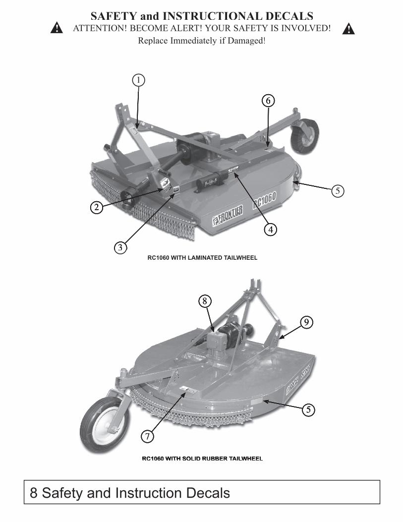
SAFETY and INSTRUCTIONAL DECALSATTENTION! BECOME ALERT! YOUR SAFETY IS INVOLVED!
Replace Immediately if Damaged!
8 Safety and Instruction Decals
1
2
33
6
5
5
7
8
9
RC1060 WITH LAMINATED TAILWHEEL
RC1060 WITH SOLID RUBBER TAILWHEELRC1060 WITH SOLID RUBBER TAILWHEEL
4
! !
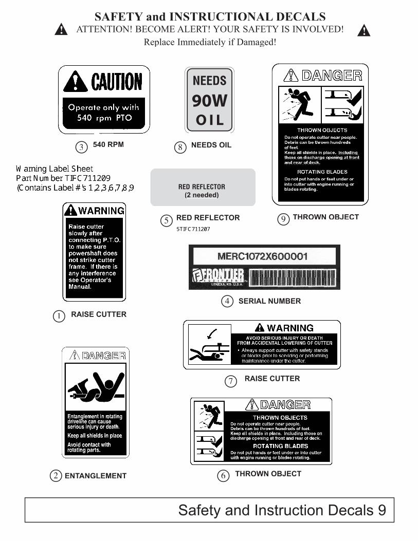
Safety and Instruction Decals 9
540 RPMPN - ME100192
3 NEEDS OILPN - ME100197
8
RED REFLECTOR PN - ME100195
5 THROWN OBJECT PN - ME100189
9
SERIAL NUMBER 4
RAISE CUTTERPN - ME100194
7
RAISE CUTTERPN - ME100190
1
ENTANGLEMENTPN - ME100191
2 THROWN OBJECT PN - ME100193
6
SAFETY and INSTRUCTIONAL DECALSATTENTION! BECOME ALERT! YOUR SAFETY IS INVOLVED!
Replace Immediately if Damaged!! !
(2 needed)

10 Description
Your 10 Series Frontier Rotary Cutter has been carefully designed for cutting grass and small brush. This manual is provided to give you the necessary operation and maintenance instructions for keeping your rotary cutter in excellent operating condition. Please read this manual thoroughly. Understand the purpose of the controls and how to use them. Observe all safety precautions on the machine and as noted throughout this manual. If any assistance or additional information is needed, contact your authorized Frontier dealer. Each cutter has free-swinging blades which reduce the shock on impact when a stationary object is hit. A shear bolt through the input shaft or slip clutch equipped driveline protects the gearbox and driveline from damage.
A-Frame
Gearbox
Driveline
Deck
Tailwheel
Major components
GENERAL DESCRIPTION
Cutter configuration: slip clutch, front and rear deflectors, iMatch hitch, and laminated tire
Manual Tube
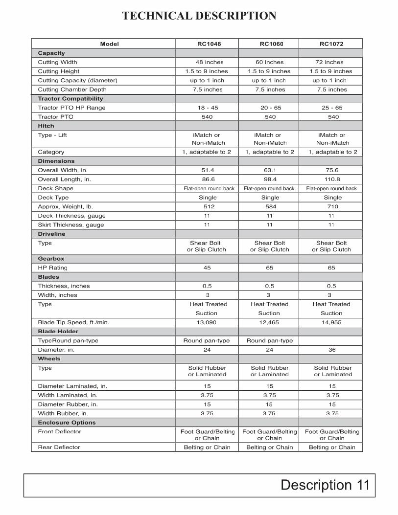
TECHNICAL DESCRIPTION
Model RC1048 RC1060 RC1072
Capacity
Cutting Width 48 inches 60 inches 72 inches
Cutting Height 1.5 to 9 inches 1.5 to 9 inches 1.5 to 9 inches
Cutting Capacity (diameter) up to 1 inch up to 1 inch up to 1 inch
Cutting Chamber Depth 7.5 inches 7.5 inches 7.5 inches
Tractor Compatibility
Tractor PTO HP Range 18 - 45 20 - 65 25 - 65Tractor PTO 540 540 540Hitch
Type - Lift iMatch or iMatch or iMatch or Non-iMatch Non-iMatch Non-iMatchCategory 1, adaptable to 2 1, adaptable to 2 1, adaptable to 2Dimensions
Overall Width, in. 51.4 63.1 75.6Overall Length, in. 86.6 98.4 110.8Deck Shape Flat-open round back Flat-open round back Flat-open round backDeck Type Single Single SingleApprox. Weight, lb. 512 584 710Deck Thickness, gauge 11 11 11Skirt Thickness, gauge 11 11 11Driveline
Type Shear Bolt Shear Bolt Shear Bolt or Slip Clutch or Slip Clutch or Slip Clutch
Gearbox
HP Rating 45 65 65Blades
Thickness, inches 0.5 0.5 0.5Width, inches 3 3 3Type Heat Treated Heat Treated Heat Treated Suction Suction Suction Blade Tip Speed, ft./min. 13,090 12,465 14,955Blade Holder
TypeRound pan-type Round pan-type Round pan-typeDiameter, in. 24 24 36Wheels
Type Solid Rubber Solid Rubber Solid Rubber or Laminated or Laminated or Laminated
Diameter Laminated, in. 15 15 15Width Laminated, in. 3.75 3.75 3.75Diameter Rubber, in. 15 15 15Width Rubber, in. 3.75 3.75 3.75Enclosure Options
Front Deflector Foot Guard/Belting Foot Guard/Belting Foot Guard/Belting or Chain or Chain or Chain
Rear Deflector Belting or Chain Belting or Chain Belting or Chain
Description 11
12 Preparation
• Preparing the Cutter
Perform the following procedures before operating the cutter:
GearboxCheck oil level. (See Lubrication and Maintenance section.)Check hardware torque. (See Lubrication and Maintenance section.)Remove any material wound on gearbox shafts.Check oil seals for leakage.
Blades and Blade HolderInspect blades for wear or damage. (See CHECKING BLADE WEAR in Service section.)Check blade hardware torque. (See Lubrication and Maintenance section.)Check blade holder hardware torque. (See Lubrication and Maintenance section.)
Hitch PinsCheck torque on hitch pin lock nut.Insure all bolts on cutter are fastened securely.
Lubricating the CutterLubricate cutter and driveline. (See Lubrication and Maintenance section.)
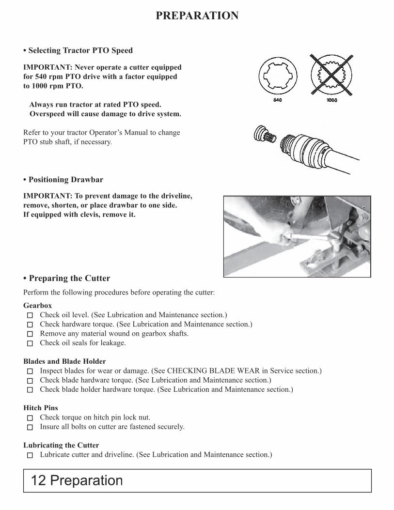
PREPARATION
• Selecting Tractor PTO Speed
IMPORTANT: Never operate a cutter equippedfor 540 rpm PTO drive with a factor equipped to 1000 rpm PTO.
Always run tractor at rated PTO speed. Overspeed will cause damage to drive system.
Refer to your tractor Operator’s Manual to changePTO stub shaft, if necessary.
• Positioning Drawbar
IMPORTANT: To prevent damage to the driveline,remove, shorten, or place drawbar to one side. If equipped with clevis, remove it.
Preparation 13
PREPARATION
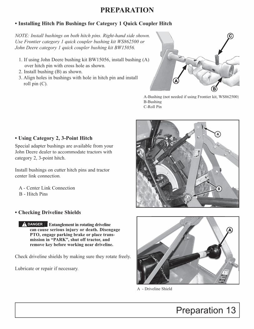
• Installing Hitch Pin Bushings for Category 1 Quick Coupler Hitch
NOTE: Install bushings on both hitch pins. Right-hand side shown. Use Frontier category 1 quick coupler bushing kit WS862500 or John Deere category 1 quick coupler bushing kit BW15056.
1. If using John Deere bushing kit BW15056, install bushing (A) over hitch pin with cross hole as shown.
2. Install bushing (B) as shown.3. Align holes in bushings with hole in hitch pin and install
roll pin (C).
• Using Category 2, 3-Point HitchSpecial adapter bushings are available from yourJohn Deere dealer to accommodate tractors withcategory 2, 3-point hitch.
Install bushings on cutter hitch pins and tractorcenter link connection.
A - Center Link Connection B - Hitch Pins
• Checking Driveline Shields
Entanglement in rotating drivelinecan cause serious injury or death. DisengagePTO, engage parking brake or place trans-mission in “PARK”, shut off tractor, andremove key before working near driveline.
Check driveline shields by making sure they rotate freely.
Lubricate or repair if necessary.
A-Bushing (not needed if using Frontier kit, WS862500)B-BushingC-Roll Pin
A
C
A
B
A - Driveline Shield
Entanglement in rotating drivelineDANGER!

• Attaching Cutter to Tractor with Quick Coupler Hitch
CAUTION: To avoid bodily injury or machine damage whenever an implement is attached,put transmission in PARK position and checkthe full range of hitch for interference, binding,or PTO separation. Do not stand betweentractor and implement.
1. Slowly push hitch control lever to lower hitch until quick coupler hooks are lower than cutter hitch pins.
2. Back up tractor to cutter hitch. 3. Raise hitch high enough to engage cutter hitch pins in hooks. 4. Engage tractor parking brake and/or place
transmission in “Park”. 5. Shut off tractor engine and remove key. 6. See ATTACHING PTO DRIVELINE in this section.
• Attaching Cutter to Tractor with Three-Point Hitch
CAUTION: To avoid bodily injury or machinedamage whenever an implement is attached,put transmission in PARK position and checkthe full range of hitch for interference, binding,or PTO separation. Do not stand between tractorand implement.
1. Back up tractor to cutter with hitch points approximately in alignment.
2. Engage tractor parking brake and/or place transmission in “Park”.
3. Shut off tractor engine and remove key. 4. Remove center link mounting hardware and hitch
pin assemblies at both hitch masts. 5. Install tractor draft links on hitch pins. Secure with
quick-lock pins (stored on tractor draft links.) 6. Align center link with upper hole in cutter mast
straps and install center link mounting hardware.7. Tighten all link and brace hardware on iMatch
Hitch (A).8. Non iMatch Hitch link clevis should rotate
360o freely after all hardware have been installed.
ATTACHING
7. Start tractor engine.8. Slowly pull hitch control lever to raise
cutter. Check for interference. (See CHECKING DRIVELINE/CUTTERCLEARANCE in this section.)
9. Lower cutter to ground and adjust if necessary.
A-Tractor Center Link B-Tractor Draft Links
!
!
14 Attaching
A
B
Non iMatch Hitch iMatch Hitch
NOTE: Non iMatch Hitch - After installing hardwarelink clevis should rotate 360o freely. (if it does not rotate freely, use a shorter Cat 1 top link hitch pin)
9. See ATTACHING PTO DRIVELINE in this section. 10. Start tractor engine. 11. Slowly pull hitch control lever to raise cutter. Check for interference. (See CHECKING DRIVELINE/CUTTER CLEARANCE in this section.)
12. Lower hitch to ground and adjust center link and/or lift links if necessary. (See procedures in your tractor Operator’s Manual.)
Attaching 15
ATTACHING
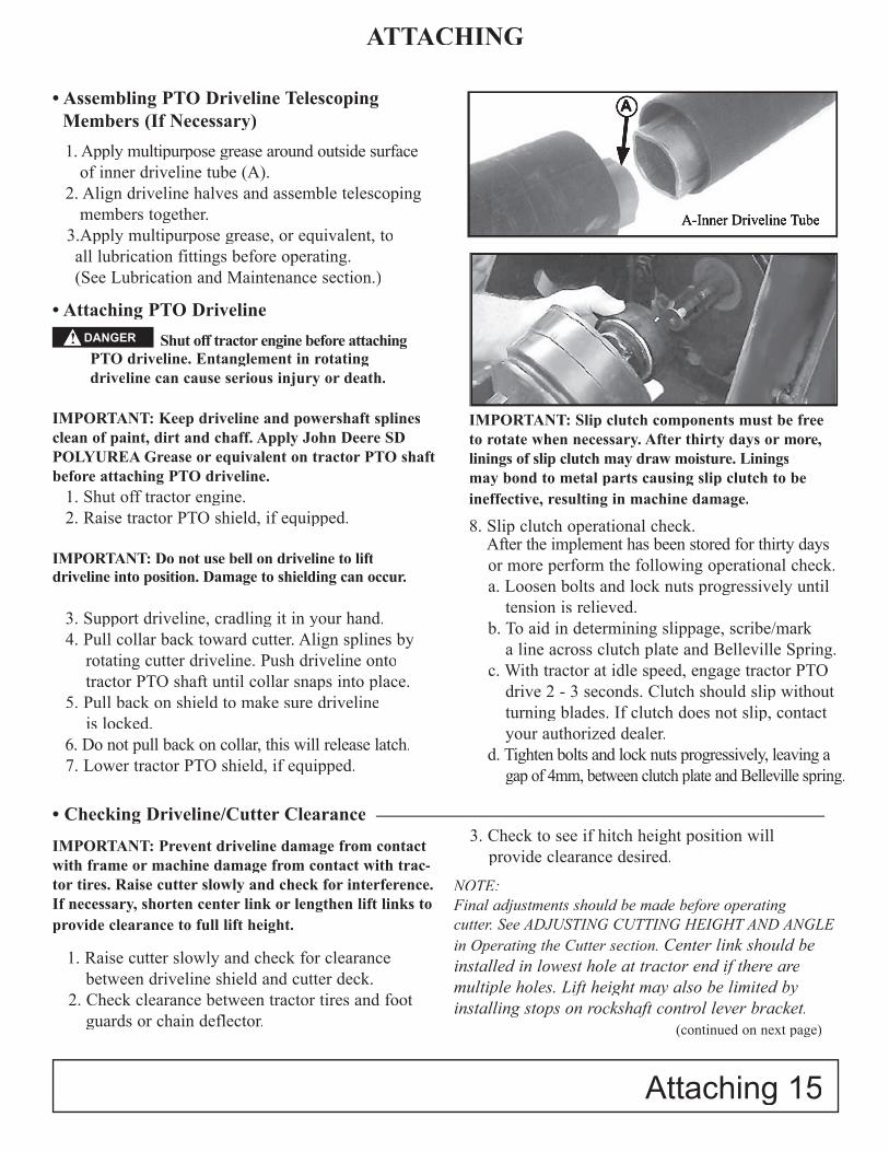
• Assembling PTO Driveline Telescoping Members (If Necessary)
1. Apply multipurpose grease around outside surface of inner driveline tube (A).2. Align driveline halves and assemble telescoping members together.
3.Apply multipurpose grease, or equivalent, to all lubrication fittings before operating. (See Lubrication and Maintenance section.)
• Attaching PTO Driveline
Shut off tractor engine before attachingPTO driveline. Entanglement in rotating driveline can cause serious injury or death.
IMPORTANT: Keep driveline and powershaft splines clean of paint, dirt and chaff. Apply John Deere SD POLYUREA Grease or equivalent on tractor PTO shaft before attaching PTO driveline.
1. Shut off tractor engine.2. Raise tractor PTO shield, if equipped.
IMPORTANT: Do not use bell on driveline to lift driveline into position. Damage to shielding can occur.
3. Support driveline, cradling it in your hand.4. Pull collar back toward cutter. Align splines by
rotating cutter driveline. Push driveline onto tractor PTO shaft until collar snaps into place.
5. Pull back on shield to make sure driveline is locked.
6. Do not pull back on collar, this will release latch.7. Lower tractor PTO shield, if equipped.
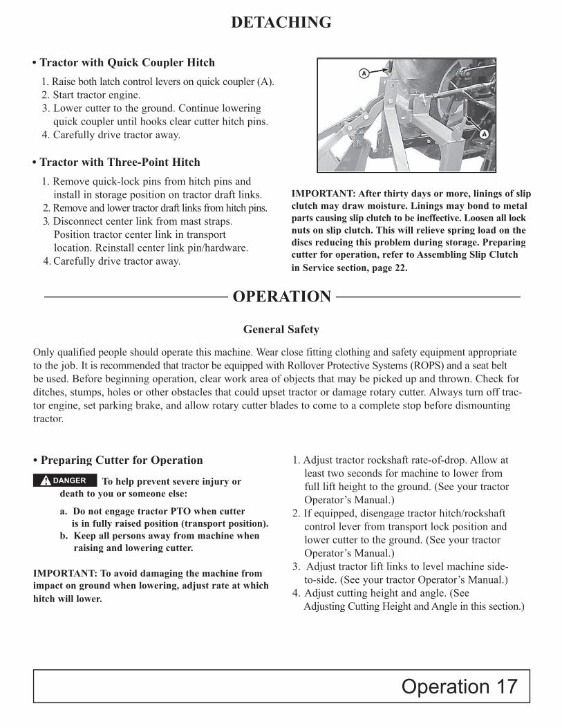
IMPORTANT: Slip clutch components must be freeto rotate when necessary. After thirty days or more, linings of slip clutch may draw moisture. Linings may bond to metal parts causing slip clutch to beineffective, resulting in machine damage.
8. Slip clutch operational check. After the implement has been stored for thirty daysor more perform the following operational check.a. Loosen bolts and lock nuts progressively until
tension is relieved.b. To aid in determining slippage, scribe/mark
a line across clutch plate and Belleville Spring.c. With tractor at idle speed, engage tractor PTO
drive 2 - 3 seconds. Clutch should slip without turning blades. If clutch does not slip, contact your authorized dealer.
d. Tighten bolts and lock nuts progressively, leaving a gap of 4mm, between clutch plate and Belleville spring.
A-Inner Driveline Tube
A
• Checking Driveline/Cutter Clearance
IMPORTANT: Prevent driveline damage from contact with frame or machine damage from contact with trac-tor tires. Raise cutter slowly and check for interference. If necessary, shorten center link or lengthen lift links to provide clearance to full lift height.
1. Raise cutter slowly and check for clearance between driveline shield and cutter deck.
2. Check clearance between tractor tires and footguards or chain deflector.
3. Check to see if hitch height position will provide clearance desired.
NOTE: Final adjustments should be made before operating cutter. See ADJUSTING CUTTING HEIGHT AND ANGLE in Operating the Cutter section. Center link should be installed in lowest hole at tractor end if there are multiple holes. Lift height may also be limited by installing stops on rockshaft control lever bracket.
(continued on next page)
DANGER!

ATTACHING
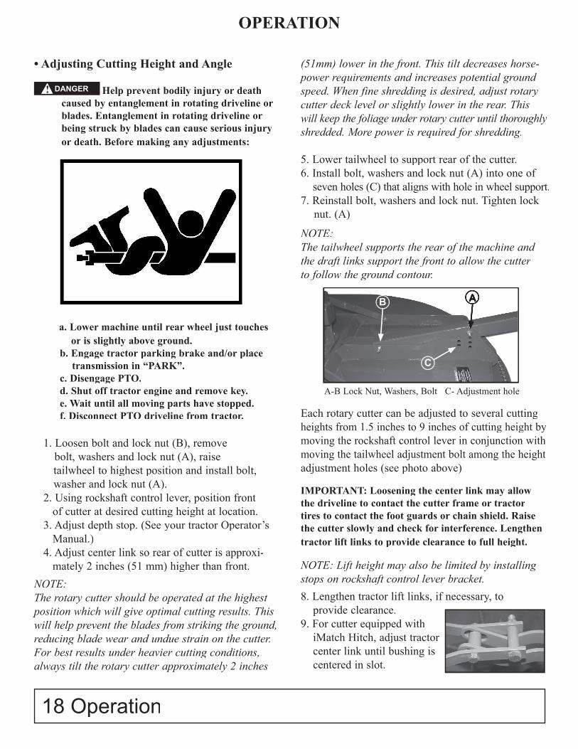
• Detaching Cutter from Tractor
CAUTION: To prevent personal injury caused by unexpected movement:
a. Park machine on a level surface.b. Engage tractor parking brake and/or
place transmission in “Park”.c. Disengage PTO.d. Shut off tractor engine and remove key.
1. Park cutter on a level surface, or block tail- wheel so machine cannot roll after detaching from the tractor.
2. Slowly push hitch control lever to lower cutter close to the ground.
3. Engage tractor parking brake and/or place transmission in “Park”.
Shut off tractor engine before detaching PTO driveline. Entanglement inrotating driveline can cause serious injuryor death.
4. Shut off tractor engine and remove key.5. Raise tractor PTO shield, if equipped.
IMPORTANT: Do not use plastic shield on driveline to hold driveline in position. Damage to shielding can occur.
6. Pull collar back toward cutter and slide drive line off tractor shaft.
7. Support and collapse driveline completely and lower onto PTO holder.
8. Lower tractor PTO shield, if equipped.
4. Shorten center link or lengthen lift links to provide clearance. (See your tractor Operator’s Manual.)
IMPORTANT: PTO driveline may be too long for some tractor models, causing tractor transaxle damage. Holddriveline sections parallel to each other and check for aminimum of 6 inches overlap.
5. Raise and lower cutter slowly to check forbinding or interference. Check cutter-to-tractordriveline telescoping length to ensure it doesnot bottom out. Modify driveline if necessary.(See MODIFING PTO DRIVELINEin Assembly section.)
16 Detaching
!
(continued on next page)
(continued from previous page)
DETACHINGDETACHING
Shut off tractor engine before DANGER!
• Tractor with Quick Coupler Hitch
1. Raise both latch control levers on quick coupler (A). 2. Start tractor engine.3. Lower cutter to the ground. Continue lowering
quick coupler until hooks clear cutter hitch pins.4. Carefully drive tractor away.
• Tractor with Three-Point Hitch
1. Remove quick-lock pins from hitch pins andinstall in storage position on tractor draft links.
2. Remove and lower tractor draft links from hitch pins.3. Disconnect center link from mast straps.
Position tractor center link in transportlocation. Reinstall center link pin/hardware.
4. Carefully drive tractor away.
IMPORTANT: After thirty days or more, linings of slip clutch may draw moisture. Linings may bond to metal parts causing slip clutch to be ineffective. Loosen all lock nuts on slip clutch. This will relieve spring load on the discs reducing this problem during storage. Preparing cutter for operation, refer to Assembling Slip Clutchin Service section, page 22.
Operation 17
DETACHING
• Preparing Cutter for Operation
To help prevent severe injury ordeath to you or someone else:
a. Do not engage tractor PTO when cutter is in fully raised position (transport position).
b. Keep all persons away from machine when raising and lowering cutter.
IMPORTANT: To avoid damaging the machine from impact on ground when lowering, adjust rate at which hitch will lower.
1. Adjust tractor rockshaft rate-of-drop. Allow atleast two seconds for machine to lower fromfull lift height to the ground. (See your tractorOperator’s Manual.)
2. If equipped, disengage tractor hitch/rockshaftcontrol lever from transport lock position andlower cutter to the ground. (See your tractor Operator’s Manual.)
3. Adjust tractor lift links to level machine side-to-side. (See your tractor Operator’s Manual.)
4. Adjust cutting height and angle. (See Adjusting Cutting Height and Angle in this section.)
General Safety
Only qualified people should operate this machine. Wear close fitting clothing and safety equipment appropriateto the job. It is recommended that tractor be equipped with Rollover Protective Systems (ROPS) and a seat belt be used. Before beginning operation, clear work area of objects that may be picked up and thrown. Check for ditches, stumps, holes or other obstacles that could upset tractor or damage rotary cutter. Always turn off trac-tor engine, set parking brake, and allow rotary cutter blades to come to a complete stop before dismounting tractor.
OPERATION
DANGER!
• Adjusting Cutting Height and Angle
Help prevent bodily injury or deathcaused by entanglement in rotating driveline or blades. Entanglement in rotating driveline or being struck by blades can cause serious injuryor death. Before making any adjustments:
a. Lower machine until rear wheel just touches or is slightly above ground.
b. Engage tractor parking brake and/or place transmission in “PARK”.
c. Disengage PTO. d. Shut off tractor engine and remove key. e. Wait until all moving parts have stopped. f. Disconnect PTO driveline from tractor.
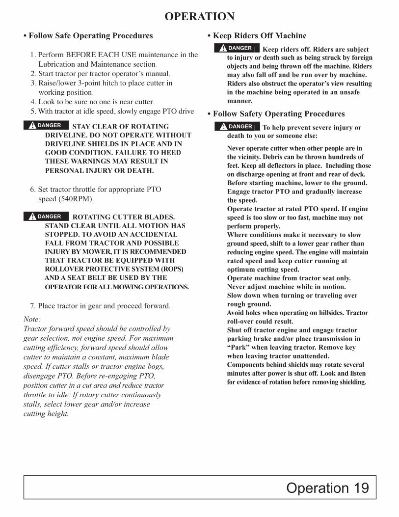
1. Loosen bolt and lock nut (B), remove bolt, washers and lock nut (A), raise tailwheel to highest position and install bolt, washer and lock nut (A).
2. Using rockshaft control lever, position front of cutter at desired cutting height at location.
3. Adjust depth stop. (See your tractor Operator’s Manual.)
4. Adjust center link so rear of cutter is approxi- mately 2 inches (51 mm) higher than front.
NOTE:The rotary cutter should be operated at the highest position which will give optimal cutting results. This will help prevent the blades from striking the ground, reducing blade wear and undue strain on the cutter. For best results under heavier cutting conditions, always tilt the rotary cutter approximately 2 inches
(51mm) lower in the front. This tilt decreases horse-power requirements and increases potential ground speed. When fine shredding is desired, adjust rotary cutter deck level or slightly lower in the rear. This will keep the foliage under rotary cutter until thoroughlyshredded. More power is required for shredding.
5. Lower tailwheel to support rear of the cutter.6. Install bolt, washers and lock nut (A) into one of
seven holes (C) that aligns with hole in wheel support.7. Reinstall bolt, washers and lock nut. Tighten lock
nut. (A)
NOTE: The tailwheel supports the rear of the machine and the draft links support the front to allow the cutterto follow the ground contour.
Each rotary cutter can be adjusted to several cutting heights from 1.5 inches to 9 inches of cutting height by moving the rockshaft control lever in conjunction with moving the tailwheel adjustment bolt among the height adjustment holes (see photo above)
IMPORTANT: Loosening the center link may allowthe driveline to contact the cutter frame or tractortires to contact the foot guards or chain shield. Raisethe cutter slowly and check for interference. Lengthen tractor lift links to provide clearance to full height.
NOTE: Lift height may also be limited by installing stops on rockshaft control lever bracket.
8. Lengthen tractor lift links, if necessary, toprovide clearance.
9. For cutter equipped withiMatch Hitch, adjust tractor center link until bushing is centered in slot.
OPERATION
18 Operation
B A
A-B Lock Nut, Washers, Bolt C- Adjustment hole
C
DANGER!
Operation 19
OPERATION
• Follow Safe Operating Procedures
1. Perform BEFORE EACH USE maintenance in the Lubrication and Maintenance section.
2. Start tractor per tractor operator’s manual.3. Raise/lower 3-point hitch to place cutter in
working position.4. Look to be sure no one is near cutter.5. With tractor at idle speed, slowly engage PTO drive.
STAY CLEAR OF ROTATING DRIVELINE. DO NOT OPERATE WITHOUTDRIVELINE SHIELDS IN PLACE AND INGOOD CONDITION. FAILURE TO HEEDTHESE WARNINGS MAY RESULT INPERSONAL INJURY OR DEATH.
6. Set tractor throttle for appropriate PTOspeed (540RPM).
ROTATING CUTTER BLADES. STAND CLEAR UNTIL ALL MOTION HASSTOPPED. TO AVOID AN ACCIDENTAL FALL FROM TRACTOR AND POSSIBLEINJURY BY MOWER, IT IS RECOMMENDEDTHAT TRACTOR BE EQUIPPED WITH ROLLOVER PROTECTIVE SYSTEM (ROPS) AND A SEAT BELT BE USED BY THEOPERATOR FOR ALL MOWING OPERATIONS.
7. Place tractor in gear and proceed forward.
Note: Tractor forward speed should be controlled bygear selection, not engine speed. For maximumcutting efficiency, forward speed should allowcutter to maintain a constant, maximum bladespeed. If cutter stalls or tractor engine bogs, disengage PTO. Before re-engaging PTO,position cutter in a cut area and reduce tractor throttle to idle. If rotary cutter continuouslystalls, select lower gear and/or increasecutting height.
• Keep Riders Off Machine
Keep riders off. Riders are subject to injury or death such as being struck by foreign objects and being thrown off the machine. Riders may also fall off and be run over by machine.Riders also obstruct the operator’s view resultingin the machine being operated in an unsafe manner.
• Follow Safety Operating Procedures
To help prevent severe injury or death to you or someone else:
Never operate cutter when other people are inthe vicinity. Debris can be thrown hundreds offeet. Keep all deflectors in place. Including thoseon discharge opening at front and rear of deck.Before starting machine, lower to the ground.Engage tractor PTO and gradually increasethe speed.Operate tractor at rated PTO speed. If enginespeed is too slow or too fast, machine may notperform properly.Where conditions make it necessary to slowground speed, shift to a lower gear rather thanreducing engine speed. The engine will maintain rated speed and keep cutter running atoptimum cutting speed.Operate machine from tractor seat only.Never adjust machine while in motion.Slow down when turning or traveling over rough ground.Avoid holes when operating on hillsides. Tractor roll-over could result.Shut off tractor engine and engage tractor parking brake and/or place transmission in “Park” when leaving tractor. Remove keywhen leaving tractor unattended.Components behind shields may rotate several minutes after power is shut off. Look and listen for evidence of rotation before removing shielding.
DANGER!
DANGER!
Keep riders off. Riders are subject DANGER!
To help prevent severe injury or DANGER!

20 Lubrication and Maintenance
LUBRICATION and MAINTENANCE
• Lubricating and Maintaining Machine Safely
Help prevent bodily injury or death caused by entanglement in rotating driveline or blades. Entanglement in rotatingdriveline or being struck by blades can causeserious injury or death.
Components will be hot after operation.Let all components cool before servicing.
Replace all shields after lubricating or servicing.
• Maintenance Check List
Perform scheduled maintenance as outlined below. Lower machine to ground, turn off tractor and set parking brake before doing maintenance inspections or work. All bolts should be torqued as recommended in the Torque Specifi cations unless otherwise indicated.
• Maintenance Before Each Use
CAUTION: Do not clean, lubricate, or adjustmachine while it is in motion.
1. Check tractor tire air pressure. Refer to tractor operator’s manual.
2. Check blades and spindles to be sure that no foreignobjects such as wire or steel strapping bands arewrapped around them.
3. Check blade bolts for tightness. (Tighten to 425 ft. /lbs.)
IMPORTANT: Operating with loose blade hardwarewill damage the blade holder and blades.
a. RC1048: Remove tailwheel tube assembly support. (See REMOVING AND INSTALLING
TAILWHEEL SUPPORT in Service section.)b. Locate blade hardware under hole.
Note: Blade bolt tightening requires a 1 1/2” socket with extension, a torque multiplier, and a torque wrench to torque nut to 425 ft./lbs.
c. RC1048: Reinstall tailwheel tube assemblysupport in original position.
4. Inspect blades for wear. (See SERVICE SECTION
Checking Blade Wear). Always replace bothblades on blade holder with genuine Frontier parts.
5. Make certain driveline shields are in place andin good repair.
6. Inspect tailwheel for wear, damage, or foreign objects. (Repair or replace if necessary.)
7. Before each use refer to LUBRICATION LOCATIONS
AND INTERVALS in this section. 8. During operation, listen for abnormal sounds
which might indicate loose part, damagedbearings, or other damage.
• Maintenance After Each Use
1. Clean all debris from rotary cutter especiallyunder side of deck. When cleaning undersideof deck, securely block machine into position.
IMPORTANT: To help prevent structural damage caused by lose hardware, check all hardware afterfirst eight (8) hrs of use and tighten all hardwareto specifications.
• Observe Lubrication SymbolsLubricate with John Deere SD POLYUREA GREASE or equivalent SAE multipurpose-type grease (unless otherwise specifi ed) at hourly intervalsindicated on the symbols.
!
DANGER!

LUBRICATION and MAINTENANCE
• Lubrication Before Each Use1. Driveline Universal Joints
a. Apply multi-purpose grease with a grease gun.
2. Driveline Guard b. Apply 2-3 shots of multipurpose grease with grease gun to plastic fi tting.
3. Driveline Profi le c. Disconnect PTO Driveline. d. Pull two sections apart. e. Apply thin coat of multi-purpose grease to inside of female section. f. Re-assemble sections.
Note: Pull each section to be sure driveline and shields are securely connected. Make certain PTO shielding is in good condition. Do not grease outer or inner plastic shields.
4. Tailwheel Pivot Tubeg. Apply multi-purpose grease with grease gun.
5. Tailwheelh. Apply multi-purpose grease with grease gun.
6. Gearbox i. Check oil level by removing oil level check
plug on side of gearbox. j. Add EP80-90W gear oil if necessary to bring
oil level to check plug hole.
Lubrication and Maintenance 21
(6) Before Each Use
(5) Before Each Use(5) Before Each Use
(4) Before Each Use(4) Before Each Use(3) Before Each Use(3) Before Each Use
(2) Before Each Use(2) Before Each Use
(1) Before Each Use(1) Before Each Use
d. Pull two sections apart.

SERVICE
22 Service
• Practice Safe Service Procedures
CAUTION: To help prevent personal injury caused by unexpected movement, be sure toservice machine on a level surface.
Before servicing or adjusting machine connected to a tractor:
1. Lower machine to the ground. 2. Engage tractor parking brake and/or place transmission in “Park”. 3. Disengage PTO. 4. Shut off tractor engine and remove key. 5. Wait until all moving parts have stopped. 6. Disconnect PTO driveline from tractor.
The blades and blade pan may rotate for several minutes after PTO is shut off. Look and listen for rotating driveline to stop before working on the cutter.
When servicing blades or blade pan, it will be necessary to work underneath cutter. Be sure to support cutter frame at all four corner locations with safety shop stands to prevent accidental lowering. Do not position safety stands under wheel support because these components can rotate.
• Disassembling and Assembling Driveline Shields
1. Separate telescoping parts. 2. Remove driveline shield screw (B). 3. Rotate cone to align tab (C) with hole (A) and slide shield rearward off of driveline. 4. Assemble in reverse order.
• Disassembling and Inspecting Slip Clutch
1. Remove slip clutch driveline. (See procedure in this section.)
NOTE: Belleville springs, which are part of the clutch, keep tension on all components. When disassembling, release tension by loosening hardware progressively.
2. Loosen bolts and lock nuts progressively until tension is relieved. 3. Friction disks may appear to be part of the hub or yoke, tap lightly on edge to separate. 4. Inspect clutch components for wear or damage. Repair or replace parts as necessary.
!
B
B
C
BAABAB
• Assembling Slip ClutchAssemble slip clutch in reverse order of disassemblyusing the following instructions:
1. Install belleville spring with concave side facing away from yoke end.
IMPORTANT: To avoid driveline damage, DO NOT overtighten bolts and lock nuts. A gap must be left between clutch plate (B) and belleville spring (C).
2. Tighten bolts and lock nuts progressively, leaving a gap (A) 4mm, between clutch plate (B) and Belleville spring (C).
(Service continued on next page)

Service 23
SERVICE
• Removing and Installing Driveline-Slip Clutch
1. Disconnect driveline shield chain. 2. Open access panel on shield. 3. Remove driveline assembly from gearbox output shaft by removing 1/2” x 3” Gr 8 bolt and lock nut. 4. Make repairs as necessary: a. Slip clutch service - See DISASSEMBLING
AND INSPECTING SLIP CLUTCH in this section.
b. Driveline repair - See your John Deere dealer.
IMPORTANT: Apply multipurpose grease on gearbox input shaft. 1/2” x 3” Gr 8 bolt and lock nut required to attach driveline to gearbox input shaft.
5. Install driveline in reverse order of removal.
NOTE: Slip clutch shield removed for illustration purposes.
(Service continued from previous page)
A
BC D
AA
4mm4mm
A
A - GapB - Clutch PlateC - Belleville SpringD - Cap Screw Lock Nut (6 used)
1/2” x 3” Gr 8 bolt
(Disconnect driveline shield chain)
shield chain
SERVICE
24 Service
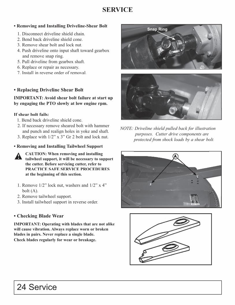
• Removing and Installing Driveline-Shear Bolt
1. Disconnect driveline shield chain.2. Bend back driveline shield cone.3. Remove shear bolt and lock nut.4. Push driveline onto input shaft toward gearbox and remove snap ring.5. Pull driveline from gearbox shaft.6. Replace or repair as necessary.7. Install in reverse order of removal.
• Replacing Driveline Shear Bolt
IMPORTANT: Avoid shear bolt failure at start upby engaging the PTO slowly at low engine rpm.
If shear bolt fails:1. Bend back driveline shield cone.2. If necessary remove sheared bolt with hammer and punch and realign holes in yoke and shaft.3. Replace with 1/2” x 3” Gr 2 bolt and lock nut.
• Removing and Installing Tailwheel Support
CAUTION: When removing and installing tailwheel support, it will be necessary to supportthe cutter. Before servicing cutter, refer toPRACTICE SAFE SERVICE PROCEDURES at the beginning of this section.
1. Remove 1/2” lock nut, washers and 1/2” x 4” bolt (A).
2. Remove tailwheel support.3. Install tailwheel support in reverse order.
• Checking Blade Wear
IMPORTANT: Operating with blades that are not alike will cause vibration. Always replace worn or broken blades in pairs. Never replace a single blade.Check blades regularly for wear or breakage.
NOTE: Driveline shield pulled back for illustration purposes. Cutter drive components are protected from shock loads by a shear bolt.
A
Snap Ring
!
Service 25
SERVICE
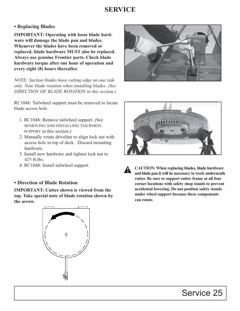
• Replacing Blades
IMPORTANT: Operating with loose blade hard-ware will damage the blade pan and blades. Whenever the blades have been removed or replaced, blade hardware MUST also be replaced. Always use genuine Frontier parts. Check blade hardware torque after one hour of operation and every eight (8) hours thereafter.
NOTE: Suction blades have cutting edge on one side only. Note blade rotation when installing blades. (See DIRECTION OF BLADE ROTATION in this section.)
RC1048: Tailwheel support must be removed to locate blade access hole.
1. RC1048: Remove tailwheel support. (See REMOVING AND INSTALLING TAILWHEEL
SUPPORT in this section.) 2. Manually rotate driveline to align lock nut with access hole in top of deck. Discard mounting hardware. 3. Install new hardware and tighten lock nut to 425 ft-lbs. 4. RC1048: Install tailwheel support.
• Direction of Blade RotationIMPORTANT: Cutter shown is viewed from the top. Take special note of blade rotation shown by the arrow.
CAUTION: When replacing blades, blade hardwareand blade pan it will be necessary to work underneathcutter. Be sure to support cutter frame at all fourcorner locations with safety shop stands to preventaccidental lowering. Do not position safety standsunder wheel support because these componentscan rotate.
!
SERVICE
26 Service/Storage
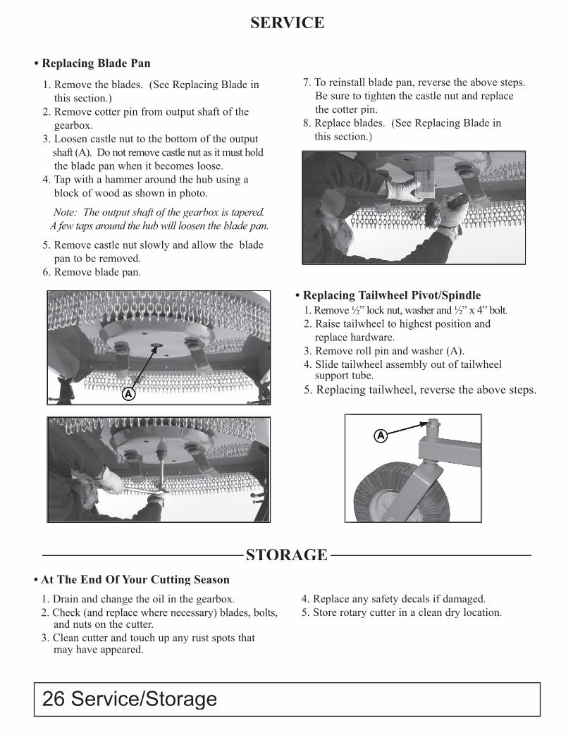
• Replacing Blade Pan
1. Remove the blades. (See Replacing Blade in this section.)2. Remove cotter pin from output shaft of the
gearbox.3. Loosen castle nut to the bottom of the output
shaft (A). Do not remove castle nut as it must hold the blade pan when it becomes loose.4. Tap with a hammer around the hub using a
block of wood as shown in photo.
Note: The output shaft of the gearbox is tapered. A few taps around the hub will loosen the blade pan.
5. Remove castle nut slowly and allow the blade pan to be removed.6. Remove blade pan.
7. To reinstall blade pan, reverse the above steps. Be sure to tighten the castle nut and replace the cotter pin.8. Replace blades. (See Replacing Blade in this section.)
A
• Replacing Tailwheel Pivot/Spindle1. Remove 1⁄2” lock nut, washer and 1⁄2” x 4” bolt.2. Raise tailwheel to highest position and
replace hardware.3. Remove roll pin and washer (A).4. Slide tailwheel assembly out of tailwheel
support tube.5. Replacing tailwheel, reverse the above steps.
A
• At The End Of Your Cutting Season
1. Drain and change the oil in the gearbox.2. Check (and replace where necessary) blades, bolts, and nuts on the cutter.3. Clean cutter and touch up any rust spots that may have appeared.
4. Replace any safety decals if damaged. 5. Store rotary cutter in a clean dry location.
STORAGESTORAGE
Assembly 27
• Perform Predelivery Service SafelyCAUTION: Understand the predelivery procedure before doing the work.
During the assembly, test, and adjustment procedures, it may be necessary to operate drives and hydraulic systems. Stay clear of machine elements when raising or lowering machine and during operation of drivelines.
Practice good communication with other service technicians. Be aware of their actions and alert themto potential hazards.
Never lubricate, service, or adjust machine while it is running. Keep hands, feet, and clothing away from power-driven or hydraulically operated parts. If it is necessary to inspect the machine while it is in opera-tion, be alert to moving parts in the immediate area.
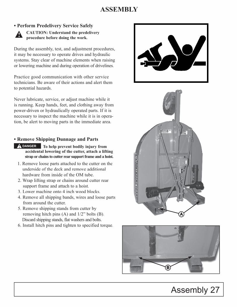
• Remove Shipping Dunnage and Parts To help prevent bodily injury from
accidental lowering of the cutter, attach a lifting strap or chains to cutter rear support frame and a hoist.
1. Remove loose parts attached to the cutter on the underside of the deck and remove additional hardware from inside of the OM tube.
2. Wrap lifting strap or chains around cutter rear support frame and attach to a hoist.
3. Lower machine onto 4 inch wood blocks.4. Remove all shipping bands, wires and loose parts
from around the cutter.5. Remove shipping stands from cutter by
removing hitch pins (A) and 1/2” bolts (B). Discard shipping stands, flat washers and bolts.
6. Install hitch pins and tighten to specified torque.
ASSEMBLY
!
A
B
DANGER!
28 Assembly
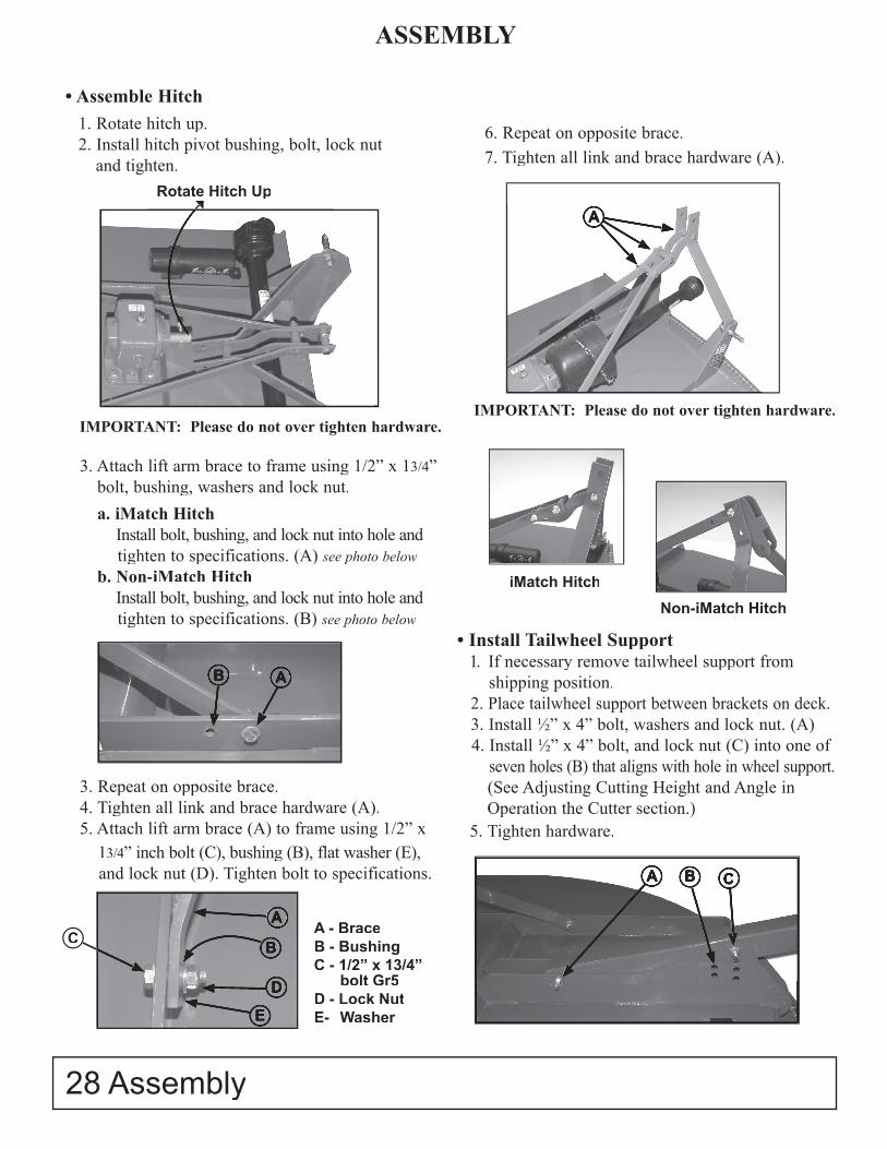
ASSEMBLY
• Assemble Hitch1. Rotate hitch up.2. Install hitch pivot bushing, bolt, lock nut
and tighten.
3. Attach lift arm brace to frame using 1/2” x 13/4” bolt, bushing, washers and lock nut.
a. iMatch Hitch Install bolt, bushing, and lock nut into hole and tighten to specifications. (A) see photo below
b. Non-iMatch Hitch Install bolt, bushing, and lock nut into hole and tighten to specifications. (B) see photo below
3. Repeat on opposite brace.4. Tighten all link and brace hardware (A).5. Attach lift arm brace (A) to frame using 1/2” x
13/4” inch bolt (C), bushing (B), flat washer (E), and lock nut (D). Tighten bolt to specifications.
6. Repeat on opposite brace.7. Tighten all link and brace hardware (A).
Rotate Hitch Up
iMatch Hitch
Non-iMatch Hitch
A
CA
B
D
E
A - BraceB - BushingC - 1/2” x 13/4”
bolt Gr5D - Lock NutE- Washer
B A
• Install Tailwheel Support 1. If necessary remove tailwheel support from shipping position. 2. Place tailwheel support between brackets on deck. 3. Install 1⁄2” x 4” bolt, washers and lock nut. (A) 4. Install 1⁄2” x 4” bolt, and lock nut (C) into one of seven holes (B) that aligns with hole in wheel support. (See Adjusting Cutting Height and Angle in
Operation the Cutter section.) 5. Tighten hardware.
A B C
IMPORTANT: Please do not over tighten hardware.IMPORTANT: Please do not over tighten hardware.
Assembly 29
ASSEMBLY
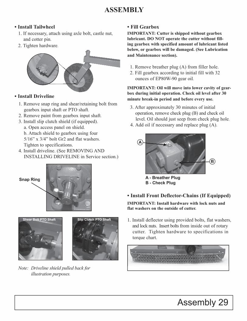
• Install Tailwheel1. If necessary, attach using axle bolt, castle nut,
and cotter pin.2. Tighten hardware.
• Install Driveline1. Remove snap ring and shear/retaining bolt from
gearbox input shaft or PTO shaft.2. Remove paint from gearbox input shaft.3. Install slip clutch shield (if equipped).
a. Open access panel on shield. b. Attach shield to gearbox using four 5/16” x 3/4” bolt Gr2 and flat washers. Tighten to specifications.
4. Install driveline. (See REMOVING AND INSTALLING DRIVELINE in Service section.)
• Fill GearboxIMPORTANT: Cutter is shipped without gearbox lubricant. DO NOT operate the cutter without fill-ing gearbox with specified amount of lubricant listed below, or gearbox will be damaged. (See Lubrication and Maintenance section).
1. Remove breather plug (A) from filler hole. 2. Fill gearbox according to initial fill with 32 ounces of EP80W-90 gear oil.
IMPORTANT: Oil will move into lower cavity of gear-box during initial operation. Check oil level after 30 minute break-in period and before every use.
3. After approximately 30 minutes of initial operation, remove check plug (B) and check oil
level. Oil should just seep from check plug hole. 4. Add oil if necessary and replace plug (A).
• Install Front Deflector-Chains (If Equipped)IMPORTANT: Install hardware with lock nuts andflat washers on the outside of cutter.
1. Install deflector using provided bolts, flat washers,and lock nuts. Insert bolts from inside out of rotarycutter. Tighten hardware to specifications intorque chart.
Snap Ring
Note: Driveline shield pulled back forillustration purposes.
Slip Clutch PTO ShaftShear Bolt PTO Shaft
A
A - Breather Plug B - Check Plug
B

30 Assembly
ASSEMBLY
• Install Front Deflector-Rubber (If Equipped)
IMPORTANT: Install hardware with lock nuts and flat washers on the outside of cutter.
1. Install deflector using two (2) foot guards (See INSTALL FOOT GUARDS in this section) and provided bolts, flat washers, and lock nuts. Insert
bolts and flat washer from inside out of rotary cutter. 2. Start with holes closest to center of machine and
work towards outside edge of the rotary cutter, inserting bolts and flat washers.
3. For best results, stretch rubber towards outside edge of rotary cutter as lock nuts are tightened.
• Install Foot Guards (If Equipped)
NOTE: Foot guards are also used with rubber front safety shield.
IMPORTANT: Install hardware with lock nuts and flat washers on the outside of cutter.
1. Install guards on each side of machine with long leg toward center of cutter and fasten with the
Two (2) bolts, flat washers and lock nuts provided per guard. Insert bolts and flat washer from inside out of rotary cutter. Tighten hardware to specifications in torque chart.
• Install Rear Deflector-Chains (If Equipped)
IMPORTANT: Install hardware with lock nuts and flat washers on the outside of cutter.
1. Install deflector using provided bolts, flat washers, and lock nuts. Insert bolt and flat washer from inside out of rotary cutter. Tighten hardware to specifications in torque chart.
• Install Rear Deflector-Rubber (If Equipped)
IMPORTANT: Install hardware with lock nuts and flat washers on the outside of cutter.
1. Install deflector 3 metal bands and provided bolts, flat washers, and lock nuts. Insert bolt and flat washer from inside out of rotary cutter.
2. Start with holes closest to center of machine and work toward outside edge of the rotary cutter,
inserting bolts and flat washers.3. For best results, stretch rubber toward outside
edge of rotary cutters as lock nuts are tightened.Tighten hardware to specifications in torque chart.
4. RC1072 only - Install bolts, and lock nuts in holes between the outside metal bands and the inside metalbands with bolt head and flat washser on inside ofcutter and flat washer and lock nut on outside of cutter.
RC1072 Model RC1048 & RC1060 Model& RC1060 Model&

ASSEMBLY
Assembly 31
Final Inspection and AdjustmentsIMPORTANT: PTO driveline may be too long for some tractor models, causing tractor transaxle damage.Modify driveline if necessary.
Attach rotary cutter to tractor and check cutter-to-tractor driveline telescoping length clearance. (See CHECKING DRIVELINE/CUTTER CLEARANCE in Attaching section.)
IMPORTANT: Blade hardware MUST be checked after the first hour and every eight (8) hours thereafter.
Check blade hardware torque. Re-tighten hardware after one hour of operation and every eight (8) hours thereafter.(See MAINTENCE BEFORE EACH USE in Lubrication and Maintenance section.)
MODIFY PTO DRIVELINEMODIFY PTO DRIVELINE
• Modify PTO Driveline (If Necessary)
1. To adjust the length, hold the half-shafts next to each other in the shortest working position and mark them.
2. Shorten inner and outer guard tubes equally.
3. Shorten inner and outer sliding profi les by the same length as the guard tubes.
4. Round off all sharp edges and remove burrs. Grease sliding profi les. No other changes may be made to PTO drive shaft and guard.
5. Chains must be fi tted so as to allow suffi cient articulation of the shaft in all working positions.
6. The PTO drive shaft must not be suspended from the chains!
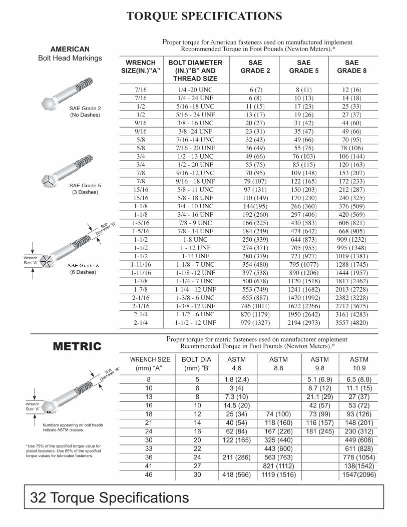
WRENCH SIZE BOLT DIA. ASTM ASTM ASTM ASTM(mm) “A” (mm) ”B” 4.6 8.8 9.8 10.9
8 5 1.8 (2.4) 5.1 (6.9) 6.5 (8.8)10 6 3 (4) 8.7 (12) 11.1 (15)13 8 7.3 (10) 21.1 (29) 27 (37)16 10 14.5 (20) 42 (57) 53 (72)18 12 25 (34) 74 (100) 73 (99) 93 (126)21 14 40 (54) 118 (160) 116 (157) 148 (201)24 16 62 (84) 167 (226) 181 (245) 230 (312)30 20 122 (165) 325 (440) 449 (608)33 22 443 (600) 611 (828)36 24 211 (286) 563 (763) 778 (1054)41 27 821 (1112) 138(1542)46 30 418 (566) 1119 (1516) 1547(2096)
Proper torque for American fasteners used on manufactured implement.Recommended Torque in Foot Pounds (Newton Meters).*
WRENCH BOLT DIAMETER SAE SAE SAESIZE(IN.)”A” (IN.)”B” AND GRADE 2 GRADE 5 GRADE 8 THREAD SIZE
7/16 1/4 -20 UNC 6 (7) 8 (11) 12 (16)7/16 1/4 - 24 UNF 6 (8) 10 (13) 14 (18)1/2 5/16 -18 UNC 11 (15) 17 (23) 25 (33)1/2 5/16 - 24 UNF 13 (17) 19 (26) 27 (37)9/16 3/8 - 16 UNC 20 (27) 31 (42) 44 (60)9/16 3/8 -24 UNF 23 (31) 35 (47) 49 (66)5/8 7/16 -14 UNC 32 (43) 49 (66) 70 (95)5/8 7/16 - 20 UNF 36 (49) 55 (75) 78 (106)3/4 1/2 - 13 UNC 49 (66) 76 (103) 106 (144)3/4 1/2 - 20 UNF 55 (75) 85 (115) 120 (163)7/8 9/16 -12 UNC 70 (95) 109 (148) 153 (207)7/8 9/16 - 18 UNF 79 (107) 122 (165) 172 (233)
15/16 5/8 - 11 UNC 97 (131) 150 (203) 212 (287)15/16 5/8 - 18 UNF 110 (149) 170 (230) 240 (325)1-1/8 3/4 - 10 UNC 144(195) 266 (360) 376 (509)1-1/8 3/4 - 16 UNF 192 (260) 297 (406) 420 (569)1-5/16 7/8 - 9 UNC 166 (225) 430 (583) 606 (821)1-5/16 7/8 - 14 UNF 184 (249) 474 (642) 668 (905)1-1/2 1-8 UNC 250 (339) 644 (873) 909 (1232)1-1/2 1 - 12 UNF 274 (371) 705 (955) 995 (1348)1-1/2 1-14 UNF 280 (379) 721 (977) 1019 (1381)
1-11/16 1-1/8 - 7 UNC 354 (480) 795 (1077) 1288 (1745)1-11/16 1-1/8 -12 UNF 397 (538) 890 (1206) 1444 (1957)1-7/8 1-1/4 - 7 UNC 500 (678) 1120 (1518) 1817 (2462)1-7/8 1-1/4 - 12 UNF 553 (749) 1241 (1682) 2013 (2728)2-1/16 1-3/8 - 6 UNC 655 (887) 1470 (1992) 2382 (3228)2-1/16 1-3/8 -12 UNF 746 (1011) 1672 (2266) 2712 (3675)2-1/4 1-1/2 - 6 UNC 870 (1179) 1950 (2642) 3161 (4283)2-1/4 1-1/2 - 12 UNF 979 (1327) 2194 (2973) 3557 (4820)
AMERICANBolt Head Markings
SAE Grade 2 (No Dashes)
SAE Grade 5 (3 Dashes)
SAE Grade 8 (6 Dashes)
Bolt
Diameter “B”
WrenchSize “A”
Proper torque for metric fasteners used on manufacturer emplement.Recommended Torque in Foot Pounds (Newton Meters).*
8.8
Bolt
Diameter “B”
WrenchSize “A”
METRIC
Numbers appearing on bolt headsindicate ASTM classes.
*Use 75% of the specifi ed torque value forplated fasteners. Use 85% of the specifi edtorque values for lubricated fasteners.
TORQUE SPECIFICATIONS
32 Torque Specifi cations

Problem Possible Cause Possible Remedy
Leaves a streak of uncut 1. Rotary cutter not level, side to side. Level 3-pt hitch linkage on tractor.or partially cut grass. 2. Blade dull or bent. Sharpen or replace blades.
3. Blades unable to cut that part of Slow ground speed of tractor but Slow ground speed of tractor but Slow ground speed of tractor but grass pressed by path of tractor tires. keep engine running at full PTO rpm. Cutting lower will help. 4. Possible build up of material under rotary cutter. Clean rotary cutter.
Blade cuts grass lower 1. Height of rotary cutter lower at rear Adjust rotary cutter height and in center of swath or at front. altitude so that rotary cutter rear &than at the edge. front are with 1/2” of same height.
Material discharges from 1. Grass or brush may be too high or thick. Reduce ground speed but maintaincutter unevenly, or discharges cutter unevenly, or discharges cutter unevenly, or discharges 540 rpm at tractor PTO, or makeclumps of grass. two passes over material. Raise rotary cutter for the fi rst pass and lower for the second pass, preferably cutting 900
to the fi rst pass. Raise rear of rotary cutter high enough to permit material to discharge.
2. Grass wet. Allow grass to dry before mowing. Slow ground speed of tractor but keep engine running at full PTO rpm. Cutting lower will help.
Gearbox overheating. 1. Low on lubricant. Fill to proper level. 2. Improper lubricant type. Replace with proper lubricant. 3. Excessive trash build up around Remove trash. gearbox.
Rotary cutter will not cut. 1. Shear bolt sheared Install new shear bolt.
Rotary cutter will not cut 2. Slip clutch slipping. Adjust slip clutch according to all the time. (slip clutch only) guidelines on page 22.
Excessive vibration. 1. Possible build up of material on blade Clean blade pan. 2. Blades locked into position. Free blades so they swing free. 3. Check for even wear on each blade tip. Weigh each blade. Weight should be with in 1 oz. Always replace both blades. 4. Broken blade. Replace blades, in set. 5. New blade or bolts not matched with worn Replace blades or bolts in sets. blade or bolts.
Gearbox noisy. 1. Low oil in gearbox. Check oil level. Add oil.
Troubleshooting Guide 33
TROUBLESHOOTING GUIDE

ItemNumber
Ship Qty. Description
1 1 Deck Assembly - RC1048 (Includes gearbox, blade pan, blades,and hitch. Does not include tailwheel assembly, driveline, or frontand rear deflectors.)
1 1 Deck Assembly - RC1060 (Includes gearbox, blade pan, blades,and hitch. Does not include tailwheel assembly, driveline, or frontand rear deflectors.)
1 1 Deck Assembly - RC1072 (Includes gearbox, blade pan, blades,and hitch. Does not include tailwheel assembly, driveline, or frontand rear deflectors.)
2 1 Frontier Logo Decal 3 1 Model Number Decal (RC1048) 3 1 Model Number Decal (RC1060) 3 1 Model Number Decal (RC1072) 4 1 Manual Tube 5 1 Lift Pin, Cat 1 5a 1 Lift Pin, Bushing 6 1 Top Link Mount 7 1 iMatch Pivot Link Kit 8 1 Non - iMatch Link Clevis 9 1 Lift Strap RC1048 and RC1060 9 1 Lift Strap RC1072 10 1 RC1048 Gearbox 45 hp 10 1 RC1060 Gearbox 65 hp 10 1 RC1072 Gearbox 65 hp 11 1 Slip Clutch Shield Cone 12 1 Tailwheel Tube Assembly for RC1048,RC1060 & RC1072 13 1 Tailwheel Fork with Roll Pin 14 1 Laminated Tailwheel 15 1 Solid Rubber Tire Tailwheel
ME300326 ME300277 ME300288 ME300283 ME300284
TIFC711172
TIFC711111TIFC711112TIFC711191
ME100561 ME100562 ME100563
TIFC711114TIFC711115TIFC711116TIFC711118TIFC711145TIFC711210TIFC711211TIFC711212
Part Number
5TIFC711287
5TIFC711286
5TIFC711288
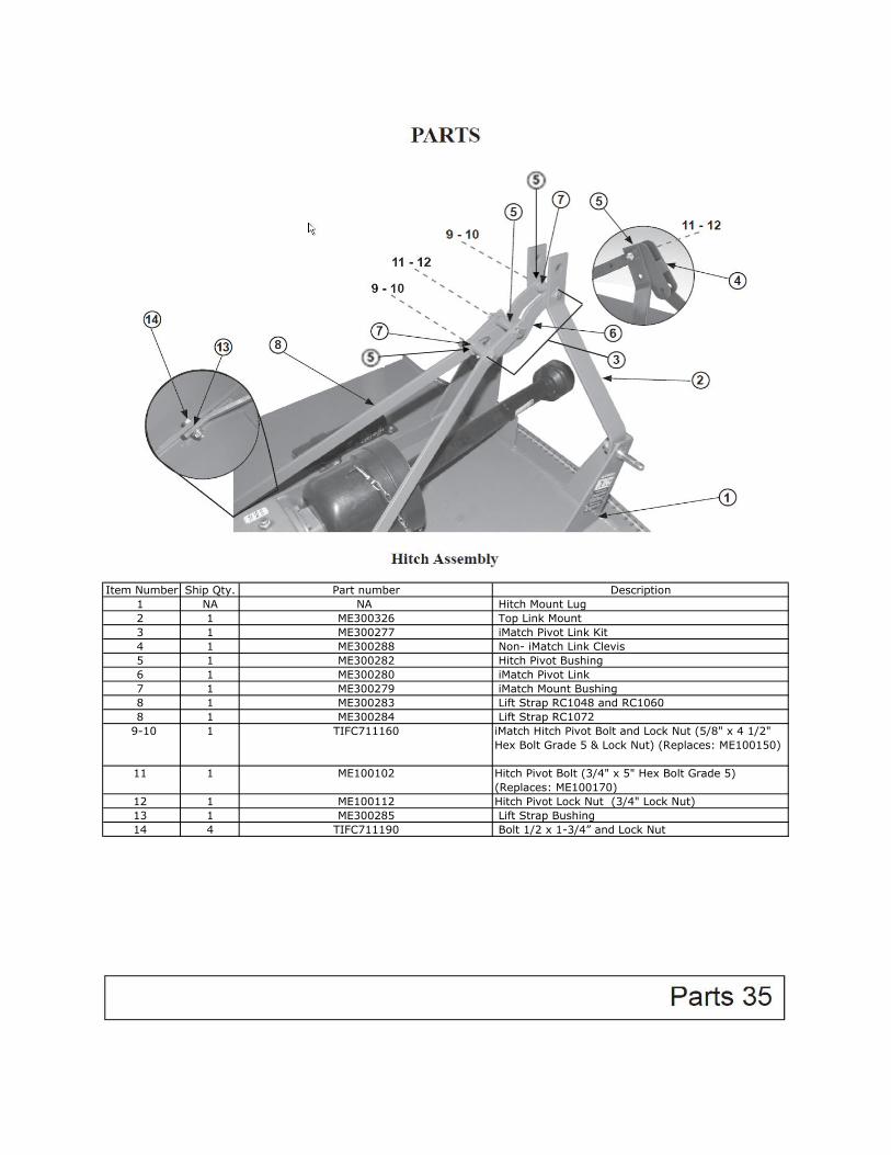
Item Number Ship Qty. Description 1 NA Hitch Mount Lug 2 1 Top Link Mount 3 1 iMatch Pivot Link Kit 4 1 Non- iMatch Link Clevis 5 1 Hitch Pivot Bushing 6 1 iMatch Pivot Link 7 1 iMatch Mount Bushing 8 1 Lift Strap RC1048 and RC1060 8 1 Lift Strap RC1072
9-10 1 iMatch Hitch Pivot Bolt and Lock Nut (5/8" x 4 1/2"Hex Bolt Grade 5 & Lock Nut) (Replaces: ME100150)
11 1 Hitch Pivot Bolt (3/4" x 5" Hex Bolt Grade 5)(Replaces: ME100170)
12 1 Hitch Pivot Lock Nut (3/4" Lock Nut) 13 1 Lift Strap Bushing 14 4 Bolt 1/2 x 1-3/4” and Lock Nut
ME100102
ME300277ME300288ME300282ME300280
ME300326
TIFC711160
TIFC711190
Part number NA
ME100112ME300285
ME300279ME300283ME300284

Item Number ShipQty.
Description
1 1 Set Blade Pan RC1048 Assembly (Blade Pan, Bolts, Blades)(Stamped pan)
1 1 Set Blade Pan RC1060 Assembly (Blade Pan, Bolts, Blades)(Stamped pan)
1 1 Set Blade Pan RC1072 Assembly (Blade Pan, Bolts, Blades)(Stamped pan)
2 1 Set Blade Set (2 Blades) RC1048(Pie-cut weld blade pan)*
2 1 Set Blade Set (2 Blades) RC1048(Stamped blade pan - No pie-cut welds)*
2 1 Set Blade Set (2 Blades) RC1060 and RC1072(Pie-cut weld blade pan.)*
2 1 Set Blade Set (2 Blades) RC1060(Stamped Blade Pan - No pie-cut welds.)*
2 1 Set Blade Set (2 Blades) RC1072(Stamped Blade Pan - No pie-cut welds.)*
3 1 Set Hex Key Blade Bolt Set (2 blade bolts and locknuts)(Pie-cut weld blade pan)*
3 1 Set Tab Key Blade Bolt Set (2 blade bolts and locknuts)Stamped Blade Pan (No pie-cut welds)*
4 1 Complete PTO Shaft/Driveline (Shear Pin) RC10484 1 Complete PTO Shaft/Driveline (Shear Pin) RC1060 and
RC10725 1 Complete PTO Shaft/Driveline (Slip Clutch) RC10485 1 Complete PTO Shaft/Driveline (Slip Clutch) RC1060 and
RC10726 1 Gearbox 45 hp - RC10486 1 RC1060 Gearbox 65 hp6 1 RC1072 Gearbox 65 hp7 1 Slip Clutch Shield Cone w/ Hardware8 4 Gearbox Mounting Bolts w/ Lock Nuts Kit (4 bolts and nuts)
9-10 1 Castle Nut w/ Cotter Pin (Gearbox output shaft)
TIFC711124
TIFC711121
TIFC711122
TIFC711123
TIFC711192
TIFC711194
TIFC711114TIFC711115TIFC711116TIFC711118
TIFC711125TIFC711126
TIFC711127TIFC711128
ME300227
Gearbox and Blade Pan Assembly
ME300125
ME300126
Part Number
ME400100
ME400101
ME400102
*Pie-cut weld

Item Number Ship Qty. Description1 1 Breather Fill Plug2 1 Oil Level Plug 1/2”3 1 Seal, Input Shaft4 10 Shear Bolt and Lock Nut Gr 24A 5 Retaining Bolt and Lock Nut
(Slip Clutch Driveshaft only - Grade 8)5 5 Snap Ring, Input Shaft6 1 Seal, Output Shaft7 1 Gearbox 45 hp - RC10487 1 RC1060 Gearbox 65 hp7 1 RC1072 Gearbox 65 hp
8-9 1 Castle Nut w/ Cotter Pin (Gearboxoutput shaft)
TIFC711114TIFC711115TIFC711116TIFC711194
TIFC711156TIFC711193
TIFC7111575TIFC711291
TIFC711155TIFC7111975TIFC711290
Part number
Item Number Qty. Qty.Shipped
Part Number Description
1 1 1 TIFC711176 Yoke 1 3/8-6 SPL2 1 1 TIFC711178 Collar Kit3 2 2 TIFC711177 Cross and Bearing Kit4 1 1 TIFC711131 Inboard Yoke Assembly RC10484 1 1 TIFC711132 Inboard Yoke Assembly RC1060, RC10725 1 1 TIFC711133 Out Shield Assembly RC10485 1 1 TIFC711134 Out Shield Assembly RC1060, RC10726 1 1 TIFC711179 Decal Out In7 1 1 TIFC711135 Inn Shield Assembly RC1048 For Shear Pin7 1 1 TIFC711136 Inn Shield Assembly RC1060, RC1072 For Shear Pin8 1 1 TIFC711137 Outer Profile Inboard Yoke Assembly RC10488 1 1 TIFC711138 Outer Profile Inboard Yoke Assembly RC1060, RC10729 1 1 TIFC711180 Decal Inn In10 1 1 TIFC711181 Yoke 1 3/8” RB, 0.531 DTNA 1 1 TIFC711125 Complete PTO Shaft/Driveline (Shear Pin) RC1048NA 1 1 TIFC711126 Complete PTO Shaft/Driveline (Shear Pin) RC1060 and
RC1072
RC10 Series Shear Bolt PTO Shaft
PARTS
Item Number Qty. Qty. Shipped Part Number Description1 1 1 TIFC711176 Yoke 1 3/8-6 SPL2 1 1 TIFC711178 Collar Kit3 2 2 TIFC711177 Cross and Bearing Kit4 1 1 TIFC711131 Inboard Yoke Assembly RC10484 1 1 TIFC711132 Inboard Yoke Assembly RC1060, RC10725 1 1 TIFC711133 Out Shield Assembly RC10485 1 1 TIFC711134 Out Shield Assembly RC1060, RC10726 1 1 TIFC711179 Decal Out In7 1 1 TIFC711166 Inn Shield Assy RC1048 for Slip Clutch7 1 1 TIFC711168 Inn Shield Assy RC1060, RC1072 for Slip Clutch8 1 1 TIFC711137 Outer Profile Inboard Yoke Assembly RC10488 1 1 TIFC711138 Outer Profile Inboard Yoke Assembly RC1060, RC10729 1 1 TIFC711180 Decal Inn In10 1 1 TIFC711188 Friction Clutch Assembly11 6 6 TIFC711182 Lock Nut12 1 1 TIFC711183 Belleville Spring13 1 1 TIFC711184 Flange Yoke14 2 2 TIFC711167 Friction Disc15 1 1 TIFC711185 Hub16 1 1 TIFC711186 Thrust Plate17 6 6 TIFC711187 BoltNA 1 1 TIFC711127 Complete PTO Shaft/Driveline (Slip Clutch) RC1048NA 1 1 TIFC711128 Complete PTO Shaft/Driveline (Slip Clutch) RC1060 and RC1072
RC10 Series Slip Clutch PTO Shaft
PARTS
ItemNumber
Ship Qty. Description
1 1 Laminated Tailwheel Assembly - Complete1a 1 Solid Rubber Tailwheel Assembly - Complete2 1 Tailwheel - Laminated Tire2a 1 Tailwheel - Solid Rubber Tire3 1 Tailwheel Fork with Roll Pin4 5 Roll Pin (Tailwheel Fork)5 1 Tailwheel Tube for RC1048, RC1060 and RC10726 1 Axle Bolt Kit Laminated Tire (does not include hub)
7 1 Axle Bolt Kit Solid Rubber Tire8 2 Bushing (Tailwheel - Solid Rubber Tire)10 2 Bushing (Tailwheel - Laminated Tire)11 5 Grease Zerk on Tube12 5 1 1/4” Flat Washer13 1 Tailwheel hub for laminated tireNA 5 Grease Zerk On Laminated Tire
TIFC711152TIFC7111475TIFC711296 TIFC711195
TIFC711196
TIFC711198ME300242
TIFC711213
TIFC711212TIFC711210TIFC711154TIFC711145
Part Number
TIFC711117TIFC711119TIFC711211
Item Number Ship Qty. Description
1 1 Rear Rubber DeflectorStrap Kit (3 Metal Strapsw/ Hardware)
2 1 Front Rubber Deflector3 1 Rear Rubber Deflector
4 1 Foot Guard w/ Hardware(pair)
5 1 5/16” x 1 1/2” Bolt Gr 56 1 5/16” Flat Washer7 1 5/16” Lock Nut
ME100202ME100142ME100135
ME100202ME100142ME100135
ME300243 ME300243
ME300212 ME300212 ME300212
TIFC711170TIFC711164 (metal
deflector lesshardware)
TIFC711171TIFC711165 (metal
deflector less hardware)
ME100202ME100142ME100135
ME300243
TIFC711169TIFC711163 (metal
deflector lesshardware)
RC1048 RC1060 RC1072Part Number Part Number Part Number
42 Parts
PARTS
Item Number Qty. Description Part Number
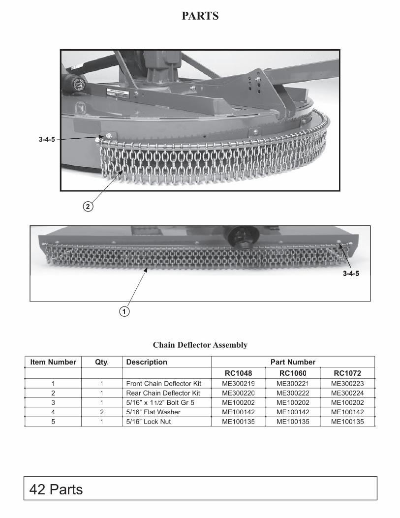
RC1048 RC1060 RC10721 1 Front Chain Deflector Kit ME300219 ME300221 ME3002232 1 Rear Chain Deflector Kit ME300220 ME300222 ME3002243 1 5/16” x 1 1/2” Bolt Gr 5 ME100202 ME100202 ME1002024 2 5/16” Flat Washer ME100142 ME100142 ME1001425 1 5/16” Lock Nut ME100135 ME100135 ME100135
1
2
3-4-53-4-5
3-4-5
Chain Deflector Assembly
