rotary wing aeroelasticity current status and future trends
TRANSCRIPT

AIAA JOURNAL
Vol. 42, No. 10, October 2004
Rotary-Wing Aeroelasticity: Current Status and Future Trends
Peretz P. FriedmannUniversity of Michigan, Ann Arbor, Michigan 48109-2140
Introduction and BackgroundConcise Perspective and Previous Surveys
W HEN reviewing research in rotary-wing aeroelasticity(RWA), it is important to mention a few historical facts. The
Wright brothers flew in 1903, and Sikorsky built and started flyingthe first operational helicopter, the R-4 or (VS-316), in 1942. TheR-4 was a three-bladed helicopter with a rotor diameter of 11.6 mand was powered by a 185-hp engine. Thus, there is an initial gapof approximately four decades between fixed-wing and rotary-wingtechnologies. Therefore, it is not surprising that certain rotary-wingproblems, particularly those pertaining to unsteady aerodynamics,are still not well understood. The situation is further compounded bythe complexity of the vehicle when compared to fixed-wing aircraft.The field of RWA has been the most active area in aeroelasticityduring the last three decades. This vigorous research activity hasgenerated a considerable number of survey papers as well as severalbooks that have been published on this topic.
These review papers, when considered in chronological order,provide a historical perspective on this evolving field.1−13 One ofthe first significant reviews of rotary-wing dynamic and aeroelasticproblems was provided by Loewy,11 where a wide range of dynamicproblems was reviewed in considerable detail. A more limited sur-vey emphasizing the role of unsteady aerodynamics and vibrationproblems in forward flight was presented by Dat.2 Two compre-hensive reviews of rotary-wing aeroelasticity were presented byFriedmann.3,4 In Ref. 3, a detailed chronological discussion of theflap-lag and coupled flap-lag-torsion problems in hover and forwardflight was presented, emphasizing the inherently nonlinear natureof the hingeless-blade aeroelastic stability problem. The nonlineari-ties considered were geometrical nonlinearities because of moderateblade deflections. In Ref. 4, the role of unsteady aerodynamics, in-cluding dynamic stall, was examined, together with the treatmentof nonlinear aeroelastic problems in forward flight. Finite elementsolutions to RWA problems were also considered, together withthe treatment of coupled rotor-fuselage problems. Another detailedsurvey by Ormiston12 discussed the aeroelasticity of hingeless andbearingless rotors, in hover, from an experimental and theoreticalpoint of view.
Peretz P. Friedmann is Francois-Xavier Bagnoud Professor of Aerospace Engineering in the Aerospace Engineer-ing Department of the University of Michigan, Ann Arbor, and Director, FXB Center for Rotary and Fixed WingAir Vehicle Design. He received his B.S. and M.S. degrees in Aeronautical Engineering from the Technion—IsraelInstitute of Technology and his Sc.D. (1972) in Aeronautics and Astronautics from the Massachusetts Instituteof Technology (MIT). Prior to entering the academic world, Dr. Friedmann worked in Israel Aircraft Indus-tries and was a Research Assistant at the Aeroelastic and Structures Laboratory at MIT. He has been with theUniversity of Michigan since January 1999. Between 1972 and 1998 he was a Professor in the Mechanical andAerospace Engineering Department of the University of California, Los Angeles. Between 1988 and 1991 he servedas the Chairman of the department. Dr. Friedmann has been engaged in research on rotary-wing and fixed-wingaeroelasticity, active control of vibrations, hypersonic aeroelasticity, flutter suppression, structural dynamics, andstructural optimization with aeroelastic constraints, and he has published extensively (more than 240 journal andconference papers). He was the recipient of the 1984 American Society of Mechanical Engineers (ASME) Struc-tures and Materials Award, and he is a Fellow of AIAA and the American Helicopter Society. He was the recipientof the AIAA Structures, Structural Dynamics, and Materials (SDM) Award for 1996, and the AIAA SDM LectureAward at the 38th SDM Conference, in 1997. He was the recipient of the Spirit of St. Louis Medal for 2003, givenby ASME, and the ASME/Boeing Structures and Materials Award in 2004.
Received 31 December 2002; revision received 31 December 2003; accepted for publication 15 February 2004. c© Copies of this paper may be made forpersonal or internal use, on condition that the copier pay the $10.00 per-copy fee to the Copyright Clearance Center, Inc., 222 Rosewood Drive, Danvers, MA01923; include the code 0001-1452/04 $10.00 in correspondence with the CCC.
Although aeroelastic stability plays an important role in the designof rotor systems, the aeroelastic response problem as represented bythe rotorcraft vibration and dynamic loads prediction plays an evenmore critical role. Thus, two other surveys have dealt exclusivelywith vibration and its control in rotorcraft.14,15 These papers focuson the vibrations caused by the aeroelastic response of the rotorand the study of various passive, semi-active and active devices forcontrolling such vibrations.
Johnson9,10 has published a comprehensive review paper address-ing both aeroelastic stability and vibration problems for advancedrotor systems. In a sequel5 to his previous review papers, Friedmanndiscussed the principal developments that have taken place between1983–1987, emphasizing new methods for formulating aeroelasticproblems, advances in treatment of the aeroelastic problem in for-ward flight, coupled rotor-fuselage analyses, structural blade mod-eling, structural optimization, and the use of active control for vi-bration reduction and stability augmentation.
A comprehensive report,13 which contains a detailed review ofthe theoretical and experimental development in the aeroelastic andaeromechanical stability of helicopters and tilt-rotor aircraft, carriedout under U.S. Army/NASA sponsorship during the period 1967–1987 was prepared by Ormiston, Warmbrodt, Hodges, and Peters.Somewhat later, key ideas and developments in four specific areas—1) role of geometric nonlinearities in RWA, 2) structural model-ing of composite blades, 3) coupled rotor-fuselage aeromechanicalproblems and their active control, and 4) higher harmonic control(HHC) for vibration reduction in rotorcraft—were considered byFriedmann.6 At the same time, Chopra1 surveyed the state of the artin aeromechanical stability of helicopters, including pitch-flap, flap-lag, coupled flap-lag-torsion, air and ground resonance. Advances inaeromechanical analysis of bearingless, circulation controlled, andcomposite rotors were also treated in this detailed paper. Perhaps themost comprehensive paper on RWA was written by Friedmann andHodges.8 This paper contains close to 350 references and dwells onall of the important aspects of rotary-wing aeroelastic stability andresponse problems. The treatment is broad and comprehensive andis current up to 1991. A partial review of some recent developmentscan also be found in Ref. 7.
1953

1954 FRIEDMANN
In addition to the numerous papers dealing with the subject of thisreview, this topic is also described in a number of books. Amongthese, the most notable one is Johnson’s16 monumental treatise onhelicopter theory, which contains extensive, detailed, and useful ma-terial on aerodynamic, dynamic, and mathematical aspects of rotary-wing aerodynamics, dynamics, and aeroelasticity. A more recentbook17 treats several aeroelastic and structural dynamic problemsin rotorcraft. Quite recently, Leishman18 has written an excellentbook on helicopter aerodynamics, which contains good treatmentsof unsteady aerodynamics, rotor wake models, and dynamic stall.
Fundamental Differences Between Rotary-Wingand Fixed-Wing Aeroelasticity
The basic problem in fixed-wing aeroelasticity is the coupledbending-torsion problem, which is essentially a linear problem. Thebasic problem in rotary-wing aeroelasticity is the coupled flap lagtorsion (CFLT) of an isolated blade, which is inherently nonlinearbecause of the geometric nonlinearities associated with moderate(or large) blade deflections that must be incorporated into the struc-tural, inertia, and aerodynamic terms associated with this aeroelasticproblem. A typical hingeless blade with an advanced geometry tip isshown in Fig. 1. The geometry of the basic CFLT problem is depictedin Fig. 2. The composite drawing depicted in Fig. 2 consists of threeparts. The top part shows a view of the deformed blade projected ona plane perpendicular to the plane of rotation. The middle portionrepresents a view of the deformed blade projected on the plane ofrotation. The bottom part represents the location of the blade crosssection before and after deformation. For the RWA problem, cou-pling between bending out of the plane of rotation (flap), bending inthe plane of rotation (lag) and torsion is critical, and neglect of oneof these degrees of freedom can produce inaccurate and misleadingresults.
Rotary-wing aeroelastic problems can be separated in tworegimes: hover and forward flight. In hover, the equations of motionhave constant coefficients, whereas in forward flight the equationshave periodic coefficients. The fundamentally nonlinear nature ofRWA requires coupling between the aeroelastic problem and theflight condition of the entire helicopter as represented by its trimstate. Two types of trim procedures, propulsive trim and wind-tunneltrim, have been used. The first trim procedure simulates straight-and-level forward-flight conditions, as shown in Fig. 3, and the secondtrim procedure corresponds to the conditions experienced when test-ing the rotor on a support in the wind tunnel.4 An important aspectof rotary-wing aeroelasticity is the coupling between the trim stateand the aeroelastic problem. This requires a simultaneous solutionof the trim and aeroelastic problems. This coupling is often ne-glected in fixed-wing analysis. Aeroelastic stability boundaries canbe obtained by linearizing equations of motion about the equilib-rium position determined from a coupled trim-aeroelastic analysis.In hover, eigenanalysis is used to obtain the aeroelastic stabilityboundaries, and in forward flight aeroelastic stability is usually de-termined from Floquet theory.4,8
The lead-lag degree of freedom, with its low aerodynamic andstructural damping, is a critical degree of freedom in most rotary-wing aeroelastic problems. Another important class of problems iscoupled rotor-fuselage aeroelastic problem that is sometimes alsodenoted by the term aeromechanical problem. This problem involvescoupling of the fuselage rigid-body degrees of freedom (primarilypitch and roll) with the blade degrees of freedom (primarily lead-lag). The geometry depicting a typical coupled rotor-fuselage of asystem is shown in Fig. 4. On the ground, the aeromechanical in-stability is called ground resonance, and in flight it is known as air
Fig. 1 Typical hingeless blade with advanced geometry tip.
Fig. 2 Undeformed and deformed blade configurations illustrating thegeometrically nonlinear aspects of the basic coupled flap-lag torsionalproblem of an elastic blade.
resonance. Although active flutter suppression has not been an areaof significant concern in RWA, active suppression of aeromechan-ical instabilities has received considerable attention. This is quitedifferent from fixed-wing aeroelasticity, where there has been a sus-tained effort to deal with active flutter suppression.7
The aeroelastic response problem that manifests itself as bladeloads, hub loads, or fuselage vibrations has a critical role for rotary-wing vehicles. Vibration prediction and its control has been an areaof intense activity. Modeling unsteady aerodynamic loads on theblade and the rotor is a major challenge. The combination of bladeadvancing and rotational speed is a source of complexity. At largeadvance ratios, many different flow regimes coexist: transonic flowwith shock waves on the advancing blade and flow reversal andlow-speed unsteady stall on the retreating blade. Time-varying wakegeometry, which is an important source of unsteady loads, vibration,and noise, is excruciatingly complex. Computation of the unsteadyfree wake has been a major challenge, and it is essential for correctcomputation of vibrations and noise. Figure 5, taken from Ref. 19,depicts three free-wake calculations based upon three different free-wake models. Rotor-fuselage interactional aerodynamics is anotherdifficult problem. Clearly, these types of problems are unique torotorcraft and are not encountered in fixed-wing aeroelasticity.
Objectives of This PaperThis paper describes developments in RWA that have taken place
during the last decade, and thus it is a companion to Ref. 8. Thepaper treats both aeroelastic stability problems as well as the aeroe-lastic response problem by describing the principal research ac-tivities on the subjects listed here: 1) recent developments in themodeling of composite rotor blades undergoing moderate and large

FRIEDMANN 1955
Fig. 3 Schematic description of the helicopter in forward flight used for coupled trim/aeroelastic analysis (propulsive trim).
Fig. 4 Coupled rotor-fuselage dynamic system, with active controlflaps shown on the blades.
deformation and their incorporation in a variety of aeroelastic sta-bility and response studies; 2) modeling of nonlinear elastomericlag dampers and their influence on aeromechanical and aeroelas-tic stability problems; 3) aeroelastic behavior of swept-tip rotorsand correlation with experiments; 4) development and validationof comprehensive helicopter analysis codes; 5) relative aeroelasticcharacteristics of hingeless and bearingless rotors; 6) developmentof improved unsteady aerodynamic models, modeling of dynamicstall, and their incorporation in aeroelastic stability and responsestudies; and 7) active control of aeroelastic stability and response(i.e., vibration) in rotorcraft.
Not all of the topics just listed are treated with the same level ofdetail. The scope of the treatment of any particular topic dependson the amount of research available as well as overall space alloca-tions within this survey. The subject of rotor loads prediction andcorrelation with experimental data has been deliberately excludedbecause it is best treated as a separate topic.
Composite Blade Models and Their ApplicationStructural dynamic and aeroelastic modeling of composite blades
undergoing moderate or large deflections and their application to thestudy of hingeless, bearingless, and tilt-rotor blade aeroelasticity aswell as coupled rotor-fuselage problems has been a particularly ac-tive area of research. Because of its importance, this research topichas also been addressed in several survey papers.8,20,21 The prin-cipal conclusions from this body of research are summarized next.The most important requirements for modeling composite helicopterblades are the capability to represent transverse shear deformation,cross-sectional warping, and elastic coupling caused by materialanisotropy, in addition to an adequate representation of geometric
nonlinearities. A most effective approach to modeling this complexbeam problem is to split the basic three-dimensional, geometricallynonlinear elasticity problem into two separate problems: 1) a ge-ometrically nonlinear, one-dimensional problem of a beam in thespanwise direction and 2) a two-dimensional linear elastic problemfrom which the warping and the cross-sectional properties at anyspanwise station are determined. This two-stage approach was intu-itively used by Kosmatka and Friedmann.22 A rigorous foundationfor this approach was established by Atilgan and Hodges23 usingan asymptotic analysis. Later this approach was further refined byCesnik et al.24,25 Finally, this approach was generalized, leading toa general cross-sectional modeling technique,26 which is linked bya variational formulation to the one-dimensional beam theory. Theauthors denote this approach by the term “dimensional reduction.”
The composite blade theories that are currently available can beseparated into three groups:
1) The first group is theories that are based on dimensional re-duction of the basic three-dimensional elasticity problem usinga variational asymptotic method. In these theories, the spanwisebeam problem is capable of handling large deformations and smallstrains. A separate finite element analysis is used to obtain the cross-sectional properties and the appropriate warping representation. Thefinite element cross-sectional analysis is capable of representing ar-bitrary cross sections, with anisotropic material properties, and avariety of wall thicknesses.23−27
2) The second group is theories based on ad hoc decoupling be-tween the geometrically nonlinear, spanwise one-dimensional beamtheory, combined with a finite element cross-sectional analysis to de-termine the cross-sectional constants and warping. In these theories,the assumption of moderate blade deflections, based on an order-ing scheme, is often used to simplify the spanwise one-dimensionalbeam model. The cross-sectional analysis is still capable of model-ing anisotropic, arbitrary cross sections, with multicell constructionand various wall thicknesses. This cross-sectional analysis is usuallylinear.22,28−31
3) The last group is theories combining assumptions on thin-walled, single-cell or two-cell, composite cross sections, with amoderate deflection type of one-dimensional beam theory. In thesetheories, shear is included, and different types of warping functionscan also be included. These theories usually provide useful and goodapproximations; however, they do not have the accuracy, generality,and logical appeal of either 1) or 2) type of theories.32−37
The composite blade models just discussed have been used fora variety of applications. A representative, but incomplete, list ofsuch applications is provided next: 1) determination of compositecoupling coefficients, twist and deformation for composite beamsor blades, for which experimental data are available,26,27,34,38,39
2) free-vibration analysis of rotating composite blades,27,29,38

1956 FRIEDMANN
a)
b)
c)
Fig. 5 Qualitative features of three different free-wake models at an advance ratio of µ= 0.1. Wake geometry: a) free-wake model, b) Johnson(modified Scully) model, and c) RotorCraft model.
3) aeroelastic behavior of composite hingeless and bearingless ro-tor blades in hover and forward flight,29−31,33,37,40−42 4) air andground resonance of helicopters with elastically tailored compos-ite blades,35 and 5) tilt-rotor aeroelastic stability and response withelastically coupled composite rotor blades.43−46
Some results taken from Ref. 31 are shown here to illustrate theeffect of composite blade construction on the aeroelastic stabilityof a typical composite hingeless helicopter blade in hover and for-ward flight. The fundamental, coupled rotating natural frequenciesof the blade in lag, flap, and torsion, respectively, are ωL1 = 0.765,ωF1 = 1.096, and ωT 1 = 3.356, when the ply orientation is zero. Thefour-bladed hingeless rotor operates at a average weight coefficientCW = 0.005 and a Lock number of γ = 5.0, with solidity σ = 0.076.
The undeformed element coordinate system for the swept-tipcomposite blade is shown in Fig. 6. The blade model belongs to cat-egory 2) described earlier in this section. The finite element nodaldegrees of freedom for the spanwise, moderate deflection beammodel are shown in Fig. 7. The two-cell composite cross section,which is analyzed by a separate finite element cross-sectional anal-ysis, is depicted in Fig. 8. Stability of the lag degree of freedom isillustrated in Fig. 9. Usually this is the degree of freedom tends tobecome unstable in hover. The effect of the composite constructionis illustrated for a straight blade where the ply angle �v in the middlevertical and the inner half of the rear vertical wall is changed between−90 deg < �v < 90 deg. As evident from the real part of this rootlocus plot, the change in ply angle can influence blade stability (i.e.,damping) substantially in both a beneficial and detrimental manner.However, it is insufficient to destabilize the blade. The imaginarypart of the plot shows the changes in the frequency of the aeroe-lastic lag mode as a result of changes in ply orientation. Numerousresults can be found in Ref. 31, where it is shown that combinationof ply orientation and tip sweep can slightly destabilize the bladein hover. Figure 10 shows the effect of ply orientation on hingelessblade stability in forward flight, at an advance ratio of µ = 0.30.For forward flight stability, information is extracted from the lin-earized perturbation equations about the coupled trim-aeroelastic
Fig. 6 Undeformed blade coordinate system, showing typical elementsof the blade span.
response in forward flight, using Floquet theory.8 The real part ofthe characteristic exponent is an indicator of the damping in thelag degree of freedom. Again, the ply angle �v is varied between−90 deg < �v < 90 deg. Although damping levels change substan-tially, ply orientation is not sufficient to destabilize the blade forthis particular case. Other results from Ref. 31 indicate that bladeresponse and loads can be changed significantly by changing plyorientation.
These results, and similar results obtained in the various stud-ies mentioned in this section, clearly indicate that composite blade

FRIEDMANN 1957
Fig. 7 Finite element nodal degrees of freedom.
Fig. 8 Two-cell composite cross section, including ply orientations Λvand Λh in the vertical and horizontal walls, respectively.
Fig. 9 Root locus for the first lag mode.
construction has considerable potential for aeroelastic tailoring lead-ing to enhanced blade stability and reduced vibratory loading in therotor. However, this remarkable potential has not been significantlyexploited by the helicopter manufacturers. Most modern helicopterblades are built of composites, primarily for their excellent fatiguecharacteristics, which result in unlimited blade life. Thus, compos-ite blades have a large advantage over the older metal blades thathad to be replaced after a few thousand hours of operation.
Fig. 10 Characteristic exponent for the fundamental lag mode at anadvance ratio of µ= 0.30.
Modeling of Elastomeric Lag Dampers and TheirIncorporation in Aeroelastic Analyses
The effect of lag dampers on aeroelastic and aeromechanical sta-bility of hingeless and bearingless rotored helicopters has alwaysbeen an important area of endeavor. During the last decade, impor-tant advances in this area have been made. The most important recentdevelopments have focused on the analytical and experimental mod-eling of the nonlinear properties of elastomeric lag dampers.47−54
The body of research in this area consists of two different ap-proaches. Gandhi and Chopra49,50 have developed a nonlinear elas-tomeric damper model, based on a combination of linear and non-linear springs and dashpots. The damper is characterized by a non-linear constitutive differential equation. This approach is capable ofcapturing, partially, the viscoelastic, hysteretic, energy-dissipatingproperties of elastomeric lag dampers, as well as dependence on op-erating conditions and steady-state lag angles. The damper model isincorporated in the ground resonance problem of an articulated rotorand in the air resonance problem of a hingeless rotor, in hover. Theblades have only flap and lag degrees of freedom, the fuselage haspitch and roll, and the damper states are appended to the equationsof motion. The results show that modeling of the dampers is impor-tant for stability prediction. However, the paper49 made no attemptto connect the damper model with any real elastomeric damper thatis in actual use. Subsequently, in Ref. 50, a slightly improved modelof the damper was incorporated in an aeroelastic and aeromechan-ical analysis of a three-bladed bearingless rotor in forward flight.Both shaft-fixed and shaft-free aeroelastic behavior were examined,and the role of the damper was found to be important. However, thedamper and its behavior were not related to an actual elastomericdamper used in a particular helicopter; an application that wouldhave further clarified the methodology.
A much more fundamental and comprehensive approach to themodeling of nonlinear lag dampers is presented in Refs. 47, 48, 53,and 54. In the first54 of these two studies, a nonlinear anelastic-displacement-field (ADF) damper model, based on accurate three-dimensional material modeling and irreversible thermodynamics,was developed from basic principles. Material nonlinearities are in-troduced by nonlinear functions that describe the dependence ofthe unrelaxed and relaxed material moduli and the anelastic strainrate, on the instantaneous total and anelastic strains. The parame-ters that characterize the nonlinear material behavior are identifiedthrough harmonic-strain-controlled experimental tests. Nonlinearfinite element equations are obtained in terms of the resulting ADFparameters.
In the second paper53 for a simplified case, corresponding topure shear behavior, two coupled partial differential equations areobtained: one describes motion, and the second governs creep

1958 FRIEDMANN
Fig. 11 Offset hinged spring-restrained hingeless blade model, coupled with an elastomeric lag damper model.
Fig. 12 Hysteretic characteristics of damper force vs lag angle for ADFdamper model.
evolution in time. The parameters required for the model im-plementation are obtained from suitable material characterizationtests. Damper behavior is modeled by a finite element method andcombined with a three-degree-of-freedom offset hinged, spring-restrained blade model, as shown in Fig. 11. Nonlinear lag damperequations are coupled with the blade equations and are solved simul-taneously. Nonlinear equations are linearized about the steady-stateresponse solution. Blade stability in forward flight is obtained fromFloquet theory. The silicon rubber damper was modeled with a sin-gle finite element. The nonlinear behavior of the elastomeric damperhas a significant effect on lag mode stability in hover and forwardflight. Damper response in forward flight depends on blade loadingand advance ratio. A good indicator of the success of this modelto predict the hysteretic behavior of lag dampers is illustrated byFig. 12. This figure shows the nondimensional lag damper forcevs lag angle for several advance ratios: µ = 0, 0.05, 0.20, and0.40, for fixed blade loading. The static lag angle decreases initiallyfrom hover to a minimum at an advance ratio of 0.20, and sub-sequently it increases. Dynamic amplitudes increase steadily withadvance ratio. Note that the ADF damper model predicts substan-tial variations in the area and aspect ratio of damper hysteresis loopswith advance ratio. The µ = 0.40 loop displays the characteristicasymmetry shown by elastomeric materials undergoing harmonicexcitation with a static bias. The elastomeric lag dampers add bothstiffness and damping to the rotor system.
In another sequel to this study,47 the model was extended to in-clude friction-type elements. These elements consist of friction-damping and linear-spring elements, which are added in parallel to
the original ADF model. The new model represents a substantialimprovement over the basic ADF model, described earlier in thissection. Thus, the peak error between predicted and experimentallydetermined material complex moduli was reduced from 72 to 18%for the storage modulus and from 90 to 10% for the loss modulus.This model represents a modification of the first generation ADFmodel54 to capture elastomeric behavior at low strain amplitude(where material nonlinearity is most significant) and over a rangeof frequencies from quasi-static to approximately 2/rev. This modelalso captured important effects such as dual-frequency stress-strainhysteresis loops.
In the final paper in this series,48 the elastomeric material de-scribed in Ref. 47 is used to design an elastomeric damper, which iscoupled with an isolated rotor aeroelastic analysis. The damper stateequations are coupled directly to the rotor-blade equations. Isolatedrotor stability, in-plane response, and damper loads in hover and for-ward flight are examined. The paper demonstrates effectively thatthe model developed is suitable for elastomeric lag damper prelim-inary design.
Aeroelastic Behavior of Swept-Tip RotorsRotor blades with swept tips, which imply both sweep and an-
hedral of the blade-tip region, shown in Fig. 1, experience bending-torsion and bending-axial coupling effects caused by sweep and an-hedral. Swept tips influence blade dynamics because they are locatedat regions of high dynamic pressure and relatively large elastic dis-placements. Swept tips enhance rotor performance and are effectivefor reducing aerodynamic noise and blade vibrations. Most modernhelicopter blades have swept tips, which sometimes are also denotedby the term advanced geometry tips. Therefore the study of aeroe-lastic behavior of rotor blades with advanced geometry tips has re-ceived considerable attention during the past decade.29−31,38,42,55−59
In Ref. 56, isotropic swept-tip rotors with advanced geometry tipshave been treated. Moderate deflection beam theory is coupled withunsteady transonic-small-disturbance theory (TSD) to calculate theunsteady transonic flow, three-dimensional effects, and shock waveson the advancing blade tips. The time history of the angle-of-attackdistributions, obtained from the rotor dynamic code, is used as inputto the finite difference TSD code. The nonuniform inflow distribu-tion over the rotor disk is calculated using a free-wake model. Thecoupling between the various analyses is carried out in a somewhatad hoc manner, which causes the results to be suitable primarily forresponse calculations, and thus blade stability was not considered.
The aeroelastic behavior of swept-tip composite blades wasconsidered in a number of detailed studies.29−31,42 The princi-pal objective of these studies was the development of a practi-cal, efficient structural dynamic model for swept-tip rotor bladesundergoing moderate deflections. Subsequently, the model was used

FRIEDMANN 1959
Fig. 13 Comparison of CAMRAD II calculations with three inflowmodels and measured hover regressing mode damping vs collective pitchangle, swept-tip blade with 2-deg precone hub, sweep 30 deg aft, and noanhedral.
to determine the effect of tip sweep and composite blade construc-tion on the aerodynamic stability of swept-tip rotor blades in hoverand forward flight. Aeroelastic blade response and blade loads inforward flight were also considered in these studies. The principalgoal of these studies was the examination of the structural couplingeffects. Therefore, the aerodynamic loads used were based uponquasi-steady Greenberg theory combined with uniform inflow. Un-steady loads were formulated using a general implicit formulation,55
which permitted the replacement of these loads by compressible un-steady loads combined with a free-wake analysis in studies that wereconducted later.60,61 Results obtained in these studies29−31,42 showthat combinations of tip sweep and composite constructions cansubstantially affect both blade stability, response, and loads.
The aeroelastic stability of straight and swept-tip rotor blades inhover and forward flight was studied both experimentally and ana-lytically in two recent comprehensive papers.57,58 Two Mach-scaledrotors, with a diameter of 7.5 ft, having both straight and swept-tipblades, were tested in hover and forward flight. The purpose of thetests was to provide hover and forward-flight data for comparisonwith analytical models. Data from the tests were compared withcalculations from a comprehensive rotor code, CAMRAD II.62,63
Correlations between test and calculations for regressing lag modedamping are shown in Fig. 13 from Ref. 58. The correlation betweentheory and experiment is very good. The aerodynamic loads werecalculated with three different inflow models: no dynamic inflow, Pitand Peters dynamic inflow, and momentum theory dynamic inflow.The differences as a result of these inflow models are small.
For forward flight, the correlation between the test results for re-gressing lag mode damping and the experimental data is not as goodas in hover as evident from Fig. 14, taken from Ref. 58. The additionof dynamic inflow increases the damping; thus, the results withoutdynamic inflow are closer to the experimental data. Subsequentlyin Ref. 57, sensitivity studies, using parameter variations in aerody-namic center, center of gravity, blade mass, torque offsets, etc., wereconducted. With these parameter variations, modest improvementsbetween theory and test results for the swept-tip rotors in forwardflight were obtained.
The studies considered in this section indicate that the accuratemodeling of aeroelastic stability and response of swept-tip rotorsstill represents a challenge, and good correlations with experimentaldata are not easily achieved.
Development and Validation of ComprehensiveHelicopter Analysis Codes
The development and validation of comprehensive helicopteranalysis codes such as CAMRAD II,62,63 2GCHAS,52,64−69
Fig. 14 Comparison with swept-tip rotor of measured forward-flightregressing-lag mode damping, CAMRAD II periodic solution withoutdynamic inflow and with dynamic inflow, 0-deg shaft angle, 6-deg col-lective pitch, 0-deg precone hub, 30-deg aft tip sweep, and no anhedral.
RDYNE,70 COPTER,71 UMARC,72 and CAMRAD/JA73 has beenanother topic that has received considerable attention. Amongthese codes, the two most advanced, CAMRAD II and 2GCHAS,have considerable capabilities that permit the treatment of com-plex configurations. The CAMRAD II code takes advantage of thearea of multibody dynamics to facilitate the treatment of complexconfigurations.74,75
Among the various comprehensive helicopter analysis codes,CAMRAD II is perhaps the most widely used, both in the UnitedStates as well as Europe and Japan. The code has been slightlymore successful than its competitors in correlating with experimen-tal data. The 2GCHAS code has also undergone considerable vali-dation during the last five years, and overall the correlations indicategenerally satisfactory predictive capability for a fairly wide rangeof rotorcraft problems. A modified and improved version of the2GCHAS code has recently become available; it is denoted by thename Rotorcraft Comprehensive Analysis Code. In addition to con-siderable improvements that enhance its computational efficiencyand reduce the run times required, the code has the added advan-tage of being able to run on PC platforms using the Linux operatingsystem.76
The UMARC code developed at the University of Maryland hasalso enjoyed considerable success, as students who graduated havetaken the code with them and started using it in an industrial setting.
Aeroelastic Characteristics of Hingelessand Bearingless Rotors
During the past three decades, the helicopter industry in theUnited States and abroad has invested a very substantial amountof resources in the development of production hingeless and bear-ingless rotor systems. Hingeless rotored helicopters, such as theMBB BO-105, and the Westland Lynx have been in productionfor almost 25 years. However, successful bearingless rotored heli-copters have gone into production only during the last decade. Typi-cal examples are the MD-900 Explorer,77 the Comanche bearinglessmain rotor (BMR),78 the Eurocopter EC135.79 Also, the MD900 andthe Comanche have five-bladed rotors, whereas the EC135 is fourbladed. This is an indication that BMR technology has matured in thepast decade, and substantial gains in the understanding of aeroelasticand aeromechanical aspects of these rotors have been made. It is alsofair to say that the improved understanding of hingeless rotor behav-ior has made significant contributions toward improved understand-ing of BMRs. This section highlights research carried out during

1960 FRIEDMANN
the past decade that has contributed towards the fundamental un-derstanding of hingeless and bearingless rotor aeroelastic behavior.
A number of theoretical studies dealing with the physical couplingmechanism present in hingeless rotored helicopters air and groundresonance in hover80 and forward flight81 have clarified the couplingmechanism between body and blade modes and the effect of forwardflight on air resonance. An aeroelastic analysis methodology forBMR helicopters in hover and forward flight was developed byGandhi and Chopra.82 The approach correlated reasonably well withshaft-fixed hover stability data obtained in tests, and then it was usedto predict shaft-free stability in forward flight. These theoreticalstudies were useful; however, work done by the helicopter industry,which is discussed next, reveals in a more comprehensive manner theadvances made in the dynamic design of hingeless and bearinglessrotor systems.
An insightful study by Weller83 provides a comparison of theaeromechanical stability characteristics, in hover, for two modelsof conventionally designed soft-in-plane main rotors. One modelis a bearingless configuration, simulating the Bell helicopter M680main rotor. The second model is a hingeless rotor similar to theMBB BO-105 main rotor. The purpose of the study was to comparethe test data obtained from the two models, identify their respectiveaeromechanical stability characteristics and determine the designfeatures that have a primary effect on the air and ground resonancebehavior in hover.
To understand better the relative aeroelastic characteristics of hin-geless vs BMRs, illustrations describing their operation are relevant.
Fig. 15 Description of the Comanche bearingless main rotor, including both elastomeric and Fluidlastic® damper configurations.
The geometry of a typical hingeless rotor was depicted in Fig. 1.The bearingless rotor with an elastomeric damper is more compli-cated and is shown in Fig. 15, taken from Ref. 78. In a bearinglessrotor, each blade is connected to the hub center by a flexural armcalled a flexbeam, which bends in lag, flap and twists by undergoingtorsional deformation. The flexbeam usually has an inboard portionthat establishes a virtual lag hinge, whereas the outboard portion isshaped so as to yield a torsionally soft region for relatively large con-trol inputs. A structurally stiff external cuff encloses the flexbeamand transmits control inputs to the blade, which are applied by thepitch link. The cuff is bolted to the blade and the flexbeam at itsoutboard end, as shown in Fig. 15. At the inboard end of the cuff, ashear-restraint mechanism, called a snubber, connects the cuff to theflexbeam. The shear restraint transmits both flapwise and lagwiseshears from the cuff to the flexure. The snubber housing containselastomeric shear pads that are used to augment structural dampingin the lead-lag or in-plane direction, and thus this combination iscalled an elastomeric lag damper, also shown in Fig. 15. To furtherclarify the operation of the bearingless hub and damper combina-tion, consider Fig. 16 taken from Ref. 79. The top portion of Fig. 16is the view of the blade from the top, and the bottom part is a sectionthrough the flexbeam, damper and control (right part) as well as asection through the damper (left side).
The mechanism, whereby the inplane bending of the flexbeamin lead lag produces displacement and damping, is illustrated byFig. 17, also from Ref. 79. Figure 17 shows the displacement be-tween the cuff and flexbeam at the location of the damper caused by

FRIEDMANN 1961
Fig. 16 Design of EC135 bearingless rotor geometry, flexbeam, andelastomeric lag damper.
Fig. 17 Chordwise kinematics showing cuff and in-plane blade bend-ing (top), which determine the modal displacement and damping of theelastomeric lag damper (bottom).
in-plane bending as well as the lead-lag damping that is produced.The shear stiffness of the damper depends on material and geometri-cal properties, environmental conditions (temperature), axial loads,as well as displacement amplitudes. The modeling of elastomericlag dampers, described in an earlier section, is an important issuein bearingless rotor design. Finally, the cuff flexbeam combinationrepresents a structural element with a redundant load path, whichhas to be modeled carefully.84
In Ref. 83, two Froude-scaled models, one hingeless and onebearingless, were tested. Although the paper does not explicitlystate the scale used, a comparison of the model radius with theMBB BO-105 blade radius reveals that it is a 1:4 scale version of theproduction rotor, and it is reasonable to assume that the bearinglessrotor was scaled in the same manner. The rotors were tested on theAdvanced Rotorcraft Experimental Dynamics system, which canprovide body pitch and roll degrees of freedom at both low and highthrust conditions. The results obtained indicate that the hingeless-rotor concept offers better stability margins at moderate to highthrust conditions because of its aeroelastic characteristics; thus, thehingeless rotor is more stable at 1 g thrust and above. For low thrustconditions, however, the bearingless rotor is better because of itslarger structural damping caused by the elastomeric lag damper.In these comparisons, it is also important to keep in mind that thehingeless rotor had no lag damper, and its damping was caused byits inherent structural damping.
In a sequel85 to this study,83 Weller conducted a very careful ex-perimental examination of a somewhat larger model BMR with adiameter of 9.37 ft. The BMR used in Ref. 83 had a diameter of7.95 ft. This was also a four-bladed rotor, with an elastomeric lagdamper similar to that considered earlier.83 Several parameters werechanged during the test, such as fundamental flap frequency, blade
Fig. 18 Hover air resonance of the minimum flight weight configura-tion with elastomeric dampers at 8-deg collective pitch.
built in cone and sweep angles, pitch link inclination, flexbeamprepitch, and shear restraint to flexure attachment. The extensiveresults show that modest changes in these parameters provided onlyvery minor improvements in the aeromechanical stability margins.The two studies mentioned83,85 contain a large amount of valuableexperimental data, but very limited correlation with analytical mod-els is provided.
An outstanding study is Ref. 78, which describes in detail theaeroelastic stability wind-tunnel testing of the Comanche BMR andpresents correlations with an analytical model. This BMR config-uration is depicted in Fig. 15. A series of wind-tunnel tests wereperformed on a 1
6 Froude-scaled model of the RAH-66 ComancheBMR at the Boeing V/STOL wind tunnel. The tests had two ob-jectives: 1) establish the aeromechanical stability characteristics ofthe coupled rotor-fuselage system, and 2) correlate the experimen-tal data with analytical stability predictions so that the methodologycan be used with confidence for the full-scale aircraft. An initial testof the rotor with elastomeric dampers, shown in Fig. 15, uncovered alimit cycle instability. This instability manifested itself for the min-imum flight weight configuration. Figure 18, taken from Ref. 78,depicts the frequency and damping of the coupled rotor-body sys-tem with elastomeric snubber/dampers. The presence of the bodydegrees of freedom and their coupling with the blade degrees of free-dom modifies significantly the dynamic characteristics compared tothe isolated rotor case. A frequency coalescence between the lag-regressing and the flap-regressing body roll mode now exists. Nearthis coalescence, the damping is low, and a limit-cycle oscillation oc-curs at the regressing lag frequency. Closer examination of this non-linear problem, presented in the paper78 revealed that this problemmight also be present when flying with the prototype flight weight.A decision was made to replace the elastomeric snubber/damper bya Fluidlastic® snubber/damper, which is also shown in Fig. 15. TheFluidlastic snubber/damper is similar to the elastomeric dampersexcept that it includes a chamber within the flat elements, which isfilled with silicone fluid to provide the blade lead-lag damping. Asthe elastomeric elements that constitute the wall of the chamber flexin shear, the fluid is forced to flow around a rigid diverter protrudinginto the fluid, thereby generating a damping force.

1962 FRIEDMANN
Fig. 19 Hover air resonance at 9-deg collective with Fluidlasticdamper.
Further study revealed that nonlinearities in the stiffness andloss factor of the elastomeric snubber/dampers were the cause ofthis limit-cycle behavior. As shown in Ref. 78, the stiffness of theFluidlastic damper is nearly linear, and using it eliminates the limit-cycle instability. Figure 19 shows the hover air response characteris-tics of the prototype flight weight configuration with the Fluidlasticdampers at 9-deg collective. The test data for both frequency anddamping are also compared with analytical results obtained from theUMARC/B code, which is a Boeing modified version of UMARC.72
The correlations between the results for the code in both hover andforward flight are quite good.
The aeromechanical design aspects of another production BMRthat is flying on the European EC135 are described in Ref. 79.The feature of this BMR equipped with an elastomeric lag damperare shown in Fig. 16. This rotor has excellent damping marginsthroughout its operation envelope. Modal damping for this rotorin level flight is shown in Fig. 20. The dots are from the flighttest, and the solid line is the result of a calculation performed byCAMRAD II. The agreement between theory and test is good. Thedamping amounts to approximately 2.5% in the rotating system.
It is remarkable that all three production BMR systems have beendeveloped during the past decade. This clearly indicates that the stateof the art of BMR aeroelastic design has made substantial advancesin this period.
Improved Unsteady Aerodynamic Modelsand Modeling of Dynamic Stall
The accurate representation of the unsteady aerodynamic loadingenvironment on rotorcraft plays a critical role in the prediction ofaeroelastic stability and response. The representation of the nonlin-ear structural portion as well as the inertial loading for the rotary-wing aeroelastic problem can be done accurately by using finiteelements and multibody techniques. However, the prediction of theunsteady aerodynamic environment presents a major challenge, andin some cases large errors in the calculation of the unsteady aero-dynamic loads cannot be avoided. When dealing with the unsteadyaerodynamic loads, it is convenient to distinguish between two sepa-rate cases: approximate unsteady aerodynamic models for attached-
Fig. 20 Regressing-lag mode damping in forward flight and compar-ison with CAMRAD II.
flow and dynamic-stall models. These topics together with their ap-plication to the rotary-wing aeroelastic problem are discussed next.
Approximate Unsteady Aerodynamic Modelsand Their Application to Aeroelastic Problems
An useful unsteady aerodynamic model that provides approxi-mate unsteady aerodynamic loads in the time domain was developedby Peters and his associates.86,87 The finite-state inflow model is anapproximate theory that provides global rotor-disk downwash underunsteady flight conditions, and it is different from airfoil theory thatproduces local downwash. The finite-state inflow theory is an ex-act representation of the three-dimensional incompressible potentialflow equations of the wake. The wake is assumed to be a cylinder inhover and a skewed cylinder in forward flight. However, the modelalso incorporates the important effect of wake contraction. Detaileddescriptions of this theory can also be found in Refs. 88 and 89. Thistheory has been employed in several aeroelastic stability studies inhover and forward flight.
A typical application of this theory to the aeroelastic stabilityof composite rotor blades in hover can be found in Ref. 90, whichintegrates geometrically exact nonlinear beam theory and the gener-alized dynamic wake theory within a finite element framework. Thetheory is applied to several examples, including limited correlationwith experimental data.
In another study,91 the three-dimensional finite-state wakemodel88 is applied to hingeless-rotor aeromechanical stability inhover and forward flight. A very interesting aspect of this study isthe correlation with experimental data for an aeromechanical sta-bility problem in which the regressing-lag mode couples with fuse-lage roll to produce an instability. Figure 21, taken from Ref. 91,shows the regressing-lag mode damping as a function of rotor speed(rpm). The dots are the experimental data, the solid line is for M = 1,which represents an earlier version of this theory,92 utilizing a singleharmonic component, and the dashed line corresponds to the three-dimensional finite-state wake model with nine harmonic wake com-ponents (M = 9). Clearly, for this particular case, there is practicallyno difference between the finite-state wake model and dynamic in-flow. The good correlation between the theory and the experimentaldata evident for the regressing-lag mode is not replicated by theother modes, as can be seen by examining the other results in thisstudy. However, in all of the cases considered, there is practically nodifference between the results based on dynamic inflow and thosebased on finite-state wake theory with nine harmonics.
Another, related, interesting study conducted recently93 attemptsto enhance the efficiency of the finite-state wake model by us-ing aerodynamic eigenmodes to develop reduced order models for
FRIEDMANN 1963
Fig. 21 Regressing-lag mode damping with increasing rotor speed at0-deg blade collective pitch.
rotorcraft. This technique, pioneered by Dowell, has proven itselfquite effective for fixed-wing and turbomachinery flows. The studyconcluded that the finite-state wake model is very compact, and itseffectiveness cannot be enhanced by reduced-order modeling.
One of the shortcomings of the finite-state wake model is its in-ability to model blade vortex interaction (BVI), which is an impor-tant source of rotor vibratory loads at lower advance ratios. To modelBVI effects, free-wake models, similar to those depicted in Fig. 5,are required. An efficient rotor free-wake model was developed byBagai and Leishman.94 This wake model has been incorporated intothe UMARC code and has been used in numerous studies sincethen.
Another new and useful approximate unsteady aerodynamic the-ory that was developed to model two-dimensional, compressibleloads for an airfoil/flap combination in unsteady freestream is pre-sented in Refs. 95 and 96. Aerodynamic loads are obtained in thefrequency domain for an airfoil/flap combination using the doublet-lattice method. Subsequently, the loads are approximated in the fre-quency domain as rational functions of the Laplace variable usinga least-squares fit to the unsteady aerodynamic loads. Transforma-tion to the time domain yields a state-space model for the unsteadyaerodynamic loads. An important feature of this approximate un-steady aerodynamic model is its ability to model the hinge momenton actively controlled flaps used for vibration reduction, which arediscussed later in this paper.
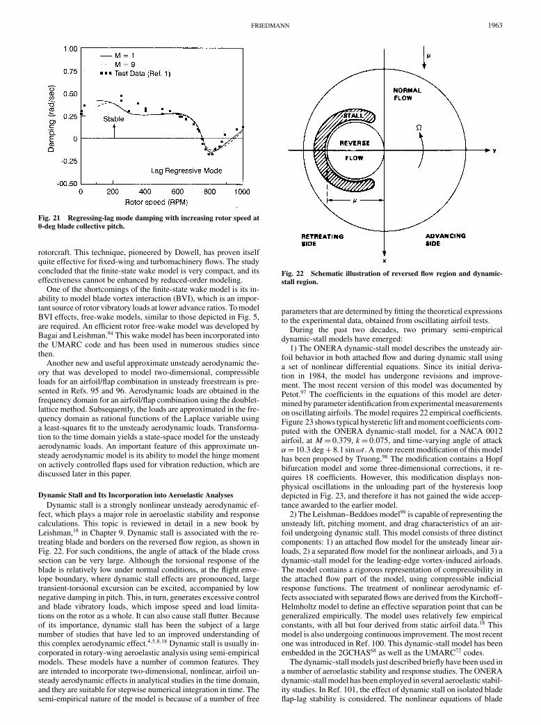
Dynamic Stall and Its Incorporation into Aeroelastic AnalysesDynamic stall is a strongly nonlinear unsteady aerodynamic ef-
fect, which plays a major role in aeroelastic stability and responsecalculations. This topic is reviewed in detail in a new book byLeishman,18 in Chapter 9. Dynamic stall is associated with the re-treating blade and borders on the reversed flow region, as shown inFig. 22. For such conditions, the angle of attack of the blade crosssection can be very large. Although the torsional response of theblade is relatively low under normal conditions, at the flight enve-lope boundary, where dynamic stall effects are pronounced, largetransient-torsional excursion can be excited, accompanied by lownegative damping in pitch. This, in turn, generates excessive controland blade vibratory loads, which impose speed and load limita-tions on the rotor as a whole. It can also cause stall flutter. Becauseof its importance, dynamic stall has been the subject of a largenumber of studies that have led to an improved understanding ofthis complex aerodynamic effect.4,5,8,18 Dynamic stall is usually in-corporated in rotary-wing aeroelastic analysis using semi-empiricalmodels. These models have a number of common features. Theyare intended to incorporate two-dimensional, nonlinear, airfoil un-steady aerodynamic effects in analytical studies in the time domain,and they are suitable for stepwise numerical integration in time. Thesemi-empirical nature of the model is because of a number of free
Fig. 22 Schematic illustration of reversed flow region and dynamic-stall region.
parameters that are determined by fitting the theoretical expressionsto the experimental data, obtained from oscillating airfoil tests.
During the past two decades, two primary semi-empiricaldynamic-stall models have emerged:
1) The ONERA dynamic-stall model describes the unsteady air-foil behavior in both attached flow and during dynamic stall usinga set of nonlinear differential equations. Since its initial deriva-tion in 1984, the model has undergone revisions and improve-ment. The most recent version of this model was documented byPetot.97 The coefficients in the equations of this model are deter-mined by parameter identification from experimental measurementson oscillating airfoils. The model requires 22 empirical coefficients.Figure 23 shows typical hysteretic lift and moment coefficients com-puted with the ONERA dynamic-stall model, for a NACA 0012airfoil, at M = 0.379, k = 0.075, and time-varying angle of attackα = 10.3 deg + 8.1 sin ωt . A more recent modification of this modelhas been proposed by Truong.98 The modification contains a Hopfbifurcation model and some three-dimensional corrections, it re-quires 18 coefficients. However, this modification displays non-physical oscillations in the unloading part of the hysteresis loopdepicted in Fig. 23, and therefore it has not gained the wide accep-tance awarded to the earlier model.
2) The Leishman–Beddoes model99 is capable of representing theunsteady lift, pitching moment, and drag characteristics of an air-foil undergoing dynamic stall. This model consists of three distinctcomponents: 1) an attached flow model for the unsteady linear air-loads, 2) a separated flow model for the nonlinear airloads, and 3) adynamic-stall model for the leading-edge vortex-induced airloads.The model contains a rigorous representation of compressibility inthe attached flow part of the model, using compressible indicialresponse functions. The treatment of nonlinear aerodynamic ef-fects associated with separated flows are derived from the Kirchoff–Helmholtz model to define an effective separation point that can begeneralized empirically. The model uses relatively few empiricalconstants, with all but four derived from static airfoil data.18 Thismodel is also undergoing continuous improvement. The most recentone was introduced in Ref. 100. This dynamic-stall model has beenembedded in the 2GCHAS68 as well as the UMARC72 codes.
The dynamic-stall models just described briefly have been used ina number of aeroelastic stability and response studies. The ONERAdynamic-stall model has been employed in several aeroelastic stabil-ity studies. In Ref. 101, the effect of dynamic stall on isolated bladeflap-lag stability is considered. The nonlinear equations of blade

1964 FRIEDMANN
Fig. 23 Typical hysteretic lift and moment coefficients computed withthe ONERA dynamic-stall model.
motion of a hingeless rotor modeled as the offset hinged springrestrained-blade model, with coupled flap-lag dynamics for eachblade, are combined with the dynamic-stall model. The nonlinearequations of blade motion are perturbed about a periodic forced re-sponse, and the damping is evaluated by Floquet eigenanalysis. Thedamping is correlated with experimental data, and the correlationis not very satisfactory. The reason for this discrepancy is probablybecause perturbation of the equations in the presence of dynamicstall is a questionable approach. A more effective approach wouldhave been to integrate the equations of motion in the time domainand extract the damping information from the response curves forthe appropriate rotor degrees of freedom. In a sequel to this study,presented in Ref. 102, the authors consider a hingeless rotor withfully coupled flap-lag torsional dynamics (two mode representa-tion for each degree of freedom), and the aerodynamic loads areobtained by a combining the ONERA dynamic-stall model with afinite-state wake model. The correlation between analysis and testis fair. Figure 24, taken from this study, depicts the influence ofdifferent levels of aerodynamic modeling: 1) blade element the-ory with quasi-steady stall, 2) the same theory but with dynamicstall, and 3) dynamic stall and finite-state wake theory. The figureshows the lag damping for a three-bladed hingeless rotor at twoshaft angles αs , over the advance ratio range 0 < µ < 0.60, and acollective pitch setting of θ0 = 3 deg. Figure 24a shows the rotoroperating at low thrust; all three models are reasonably close toexperimental data. Figure 24b depicts a large negative shaft angleαs = −16 deg, and damping decreases with advance ratio. This is alow-thrust case, and dynamic-stall and static-stall theories are close.Dynamic stall and the wake model improve the agreement at lowµ (µ < 0.20); however, these theories fail to predict the loss ofdamping at the higher advance ratio. This is somewhat surprisingbecause one would expect improved correlation with increased ad-vance ratio because dynamic-stall effects are known to be importantat high advance ratios. It is plausible that the reason for this dis-crepancy is again a result of the method used for computing thedamping, which was mentioned earlier in connection to Ref. 101.
Aeroelastic stability studies involving the Leishman dynamic-stall model were conducted by Torok and Chopra.103 The effect of
Fig. 24 Aerodynamic modeling effects on the lag damping, for a three-bladed hingeless rotor-blade model.
flow separation and dynamic stall on rotor-lag damping in high-speed flight is quite significant.
Finally, recently a European study group has completed a monu-mental report that compares several dynamic-stall models, in theirability to predict rotor behavior in the presence of dynamic stall.104
Seven different stall models were compared in this study, and thepredictions were compared with detailed measurements conductedon a model rotor in a wind tunnel. The study has identified three-dimensional phenomena as being significant. Clearly, this effect isbeyond the reach of present two-dimensional semi-empirical mod-els. This effect produces an unexpected increase in lift and momentat 0.7R blade span. The authors speculate that progress in computa-tional aerodynamics, as applied to rotors, might lead to a qualitativeexplanation of these phenomena.
Active Control of Aeroelastic Stability and Response(i.e., Vibration) in Rotorcraft
The desire to develop rotorcraft having a “jet smooth” ride hasshifted the emphasis in the area of vibration alleviation (i.e., re-duction of aeroelastic response) from traditional passive means ofvibration reduction such as vibration absorbers and isolators to ac-tive control strategies.105 Stringent requirements on vibration levelsstrive for vertical accelerations below 0.05g at most fuselage loca-tions. These requirements imply that helicopter manufacturers mightbe willing to tolerate the expense associated with an active controlsystem that operates in the rotating frame, that is, the rotor. Oncesuch a control system is present, it can also be used for additionalobjectives such as noise reduction, performance enhancement, andstabilization of aeroelastic phenomena. This section summarizesand highlights recent accomplishments in two areas: stabilizationof aeroelastic and aeromechanical phenomena and vibration reduc-tion in rotorcraft using active controls.
Stabilization of Aeromechanical and AeroelasticPhenomena by Active Controls
Some of the previous research in this area has been reviewedand discussed in Ref. 8. One of the most comprehensive studies onair resonance suppression, in hover and forward flight, using bladepitch control was carried out by Takahashi and Friedmann.106 Themodel consisted of a coupled rotor-fuselage system representing a

FRIEDMANN 1965
four-bladed hingeless rotor attached to a rigid fuselage, as depictedin Fig. 4, with pitch-and-roll degrees of freedom. The controlleroperated through a conventional swash plate that introduced thesame pitch input to all of the blades. The controller design wasbased on an optimal state estimator combined with optimal feedbackgains. Optimal loop shapes were designed using the loop transferrecovery approach. The outcome of this design process resulted ina simple controller that used a single roll-rate measurement in thebody (nonrotating frame) and suppressed air resonance by using asine and a cosine swash-plate input. The controller was shown tostabilize the system throughout a wide range of loading conditionsand forward flight speeds, with pitch inputs of 3 deg or less.
More recently, Weller107 conducted an experimental program todemonstrate the benefits of applying active rotor control techniquesto improve the aeromechanical stability characteristics of a BMRmodel. This model of the BMR was identical to that tested earlier.85
Apparently the author was unaware of the analytical work done ear-lier in this field.106 He also seemed reluctant to use modern controltechniques, and much of this work was done either experimentallyor by using an electrohydraulic simulator. Pitch-and-roll velocitiesand accelerations were measured and transformed into pylon posi-tion and velocity information, which was fed back using a fixed-gainrelationship to produce cyclic swash-plate commands θc and θs soas to increase the damping of the aeromechanical problem. Re-sults indicate the pylon position feedback could increase dampingby 1%, at most. However, destabilizing trends at high thrust werepresent. Pylon velocity feedback was superior to position feedback,and the destabilizing trends were reduced. This result is entirelyconsistent with the findings of Ref. 106. Thus, it illustrates thatexperimental trial-and-error approaches to active control, withoutthe benefits of analytical simulation and the physical understand-ing it produces, can substantially reduce the effectiveness of suchstudies.
Finally, air resonance, which is an aeromechanical instability, isa mild instability as opposed to flutter, which is an explosive insta-bility. Stabilizing flutter in rotorcraft using active control has notreceived serious consideration because it was deemed to be imprac-tical. A partial exception to this philosophy is represented by a recentexperimental study that has evaluated an approach called general-ized predictive control (GPC) to augment aeroelastic stability ofa tiltrotor operating in the airplane mode.108 The tests were per-formed on a 1
5 th scale, semispan aeroelastic model of the V-22, de-signed and built by Bell in 1981. A special tiltrotor research testbedcalled the Wing and Rotor Aeroelastic Testing System was used inthe Langley Transonic Dynamics Tunnel. The case considered isthe airplane mode, to be precise, a propeller-whirl type of instabil-ity was controlled, and strictly speaking, this is again a fixed-wingtype of aeroelastic instability. Nevertheless, because of its innova-tive nature, this was an important contribution. It was demonstratedthat using three inputs in the stationary swashplate the GPC ap-proach was highly effective in increasing the stability of the criticalwing mode, when wing responses were used as feedback. For mostcases, the damping in wing beam mode was increased from less than0.5% of critical to over 3% of critical, throughout the entire flightregime.
Recently, Celi109 has written an interesting paper on stabiliza-tion of a blade with a severed pitch link, using a trailing-edge flap,schematically depicted in Fig. 25. This study is on the boundarybetween aeroelasticity and reconfigurable controls. The failure ofthe pitch link causes the blade to be free floating and uncontrol-lable. The study indicates that the trailing-edge flap is capable ofcorrecting the catastrophic consequences of the pitch link failure bytrimming the blade, through an optimization-based trim procedure.Unfortunately, flap deflections of 18–22 deg are required, and thesecombined with actuation power requirements, which were not ad-dressed in this study, could prevent the practical implementation ofsuch a concept.
Vibration Reduction in RotorcraftAs mentioned earlier, vibration reduction in rotorcraft is essen-
tially the control of the aeroelastic response problem. Active con-
Fig. 25 Blade with severed pitch link and actively controlled trailing-edge flap.
Fig. 26 Single- or dual-ACF configuration used for vibration reduc-tion.
trol approaches to rotorcraft vibration reduction are perceived tobe a requirement so that rotorcraft can experience vibration lev-els comparable to fixed-wing transport aircraft. During the past25 years, several approaches to active vibration control in rotor-craft have emerged.105 The first approach developed was HHC. Thecontroller applies pitch inputs through a conventional swashplate.All blades experience the same inputs, and the vibratory aerody-namic loads are modified at their source, before they propagate intothe fuselage. A more promising alternative is individual blade con-trol (IBC), where time-varying pitch is introduced directly in therotating reference frame. The IBC approach can be implementedusing three different techniques. One can oscillate the entire bladein pitch by actuating it at the root; this approach was used in the ear-liest implementation of the IBC methodology. Alternatively, a smallpartial-span trailing-edge flap, shown in Fig. 26, can be actuated onthe blade; this approach is sometimes called the actively controlledflap (ACF). An even more effective approach is to use two flaps;this configuration, also shown in Fig. 26, is denoted as the dual-flapconfiguration. A third implementation twists the entire blade by em-bedding piezoelectric fibers; this approach is known as the activetwist rotor (ATR); the blade structure for this configuration is shownschematically in Fig. 27. All approaches just mentioned control vi-brations in the rotating frame. An alternative approach sometimesknown as active control of structural response (ACSR) is aimed atvibrations in the fuselage, or the fixed frame, as illustrated in Fig. 28.In this approach, stiff actuators introduce small-amplitude excitationbetween the rotor and the fuselage, such that the sum of the responseof the airframe at specified locations, because of rotor loads and theexcitation caused by controls, is reduced to a minimum.
Among various active approaches to vibration reduction, only theACSR system has been actually installed on a production helicopter,

1966 FRIEDMANN
the EH101, built by a European partnership between Westland andAgusta. All of the other systems have been tested in wind tunnels.The HHC approach and IBC scheme with root actuation have beenflight tested,105 whereas the ACF was supposed to be flight testedin early 2003 on a MD-900 Explorer, as part of the Smart Rotordemonstration program, funded by DARPA. However, instead of theflight test, the full-scale rotor with a piezoelectrically actuated ACFsystem was tested on a whirl tower in Fall 2003. The changes in theobjectives of the program were caused by a combination of technicalproblems associated with the actuation system and availability offunding.
The practical importance of active vibration control in rotorcrafthas resulted in a large number of papers on this topic during thelast decade, and to do justice to this topic would require a separatesurvey paper. Thus, only the most significant papers in this categorywill be described in this section.
Among the various active control approaches, IBC implementedusing the actively controlled flap appears to be the most promisingconcept, and therefore it has been extensively pursued. Furthermore,the ACF has also considerable potential for noise reduction and per-formance enhancement. A number of studies have established theremarkable potential of the ACF, implemented either in the single-flap or dual-flap configuration (Fig. 26), for vibration reduction us-ing a flexible blade model, with coupled flap-lag torsional dynamicsand modified Theodorsen aerodynamics that include the effect of
Fig. 27 ATR spar structure with active laminates containing piezo-electric fibers.
Fig. 28 Coupled rotor/flexible fuselage model using ACSR platform and actuators.
time-varying freestream.110−113 Milgram et al.114 have developed ananalytical simulation incorporating an unsteady compressible aero-dynamic model. The aeroelastic model was developed using thecomprehensive analysis code UMARC. Experimental results fromwind-tunnel tests of the ACF were also presented;115 the purpose ofthese early studies was to demonstrate the feasibility and effective-ness of this new approach to vibration control.
The need for an improved aeroelastic simulation model for theflap-blade combination led to the development of new and improvedmodels based on a compressible time-domain unsteady aerody-namic model. This simulation capability could accommodate threedifferent flap configurations, including dual flaps. Detailed vibra-tion reduction studies from this model were presented in Refs. 95and 116–118.
Subsequently, this model was improved by adding a free-wakemodel to the time-domain unsteady compressible theory.60,61,118,119
The resulting comprehensive simulation model facilitated the exam-ination of two distinctly different flight regimes in which vibrationsare reduced using the ACF: a high-speed flight regime, where ad-vance ratio effects are dominant and the influence of the free wakeis limited, and low or moderate advance-ratio regime where BVI areimportant. These studies have clearly demonstrated that vibrationreduction at low advance ratios (µ = 0.15) is a more demanding con-trol task because of the presence of BVI, than vibration reductionat high speeds of µ = 0.30 or higher.
During this time period, very valuable experimental results on thepractical implementation of the ACF and its application to funda-mental vibration reduction in the open-loop mode, on a two-bladedrotor, were reported by Fulton and Ormiston.120 This model rotorwas not representative of any particular full-scale configuration. Theavailability of these results permitted a comparison between thecomprehensive simulation developed61 and the experimental dataobtained by Fulton and Ormiston.120 To illustrate the vibration re-duction capability of the actively controlled flap and the reliabilityof the simulation model, some typical results obtained in Refs. 61and 119 are presented next.
The results are for a four-bladed hingeless rotor that has propertiesthat resemble the MBB BO-105 rotor. Figure 29 shows the baselineand controlled vibratory hub shears and moments, with compress-ible unsteady aerodynamics (referred to as RFA aerodynamics) anda free-wake model, at an advance ratio µ = 0.15, where BVI is im-portant. Figure 30 depicts similar results at a higher advance ratioµ = 0.30. Two important observations are relevant: 1) the vibratoryloads in the presence of BVI are approximately four times higherthan those at µ = 0.30; and 2) although the actively controlled flapis quite effective in reducing vibrations at both advance ratios, its

FRIEDMANN 1967
Fig. 29 Simultaneous reduction of 4/rev hub shears and moments(µ= 0.15), RFA aerodynamics.
Fig. 30 Simultaneous reduction of 4/rev hub shears and moments(µ= 0.30), RFA aerodynamics.
Fig. 31 Flap deflection history at advance ratios µ= 0.15 and 0.30,RFA aerodynamics.
performance in the presence of BVI is not as good as in the higheradvance ratio regime. Figure 31 depicts the flap deflections requiredfor vibration reduction at these two advance ratios; the maximumflap deflection required for the alleviation of BVI effects can exceed15 deg. Thus, BVI vibration alleviation is more demanding thanvibrations at high speed. All of the results presented were for a flapoperating in the closed-loop mode using a control law described inRefs. 61 and 119.
Fig. 32 Variation of 2/rev flapwise bending moment with elevon phase(760 rpm, µ= 0.20), RFA aerodynamics.
Fig. 33 Variation of 3/rev flapwise bending moment with elevon phase(760 rpm, µ = 0.20), RFA aerodynamics.
The simulation capability described here was also validated bycomparing it with experimental data obtained in Ref. 120 for theopen-loop operation of the flap, and the correlation in most casesis quite good. Typical results obtained in these correlation studies,which serve as a validation of the simulation capability,61,119 areshown in Figs. 32 and 33. The experiment results were obtainedon a two-bladed120 rotor at an advance ratio of µ = 0.20. Therotor was excited by flap inputs at 2, 3, 4, and 5/rev; the magnitudeof the flap input was δ f = 5 deg. The root flapping moment of theblade in the rotating system was measured. These flapping momentswere also simulated by the code. Results are shown in Fig. 32 forthe 2/rev excitation and in Fig. 33 for the 3/rev excitation. The twoblades tested were not identical, and therefore each plot contains twosets of experimental data, one for blade 1 and another for blade 2,respectively. The simulations were conducted for an average blade,and the results are shown by the triangles in Figs. 32 and 33. Clearly,the agreement between the simulation and the test is quite good.
An experimental demonstration on the feasibility of using piezo-electrically actuated flaps for vibration reduction in forward flightwas conducted by Koratkar and Chopra.121,122 The rotor was testedin the University of Maryland wind tunnel. It was a four-bladedMach scaled bearingless rotor resembling a Bell-412; the scale wasapproximately 1
7 th of full scale. The flaps were actuated by piezo-electric benders. When operating in the closed-loop mode, a neural-network controller was used. Reference 121 describes primarilyhover and open-loop tests, whereas Ref. 122 describes the closed-loop tests in forward flight. The largest flap deflections recordedwere in the range of 4 deg < |δ f | < 6 deg for components intro-duced with frequency of 1, 2, 3, 4, and 5/rev. With this control

1968 FRIEDMANN
authority, 70–90% reduction in the vibratory loads was obtained inthe advance ratio range of 0.10 < µ < 0.30 for relatively low thrustcoefficient. Comparisons between the experimental data and com-puter simulation were not presented in the paper.
A number of recent papers have also examined several issuesassociated with the practical implementation of ACF systems tothe vibration reduction problem. One important problem is that ofexcessive flap deflections, which is evident in Fig. 31, where themaximum flap deflections can reach 15 deg. These angles are largerthan angles that can be achieved with active or smart materials-basedactuation. Furthermore, in most practical cases, flap authority willhave to be limited to 3–4 deg, so as to avoid interfering with thehandling qualities of the helicopter. This has raised the issue of flapsaturation that was studied in Ref. 123, by examining three differentapproaches: 1) clipping of flap deflection, when the angles reach aprescribed value; 2) uniform scaling such that flap input harmonicsnever exceed a limiting value; and 3) an iterative, automatic, ad-justment of the control weighting matrix, so that the flap deflectionis properly constrained. It was found that the first two approachescompletely eliminated the effectiveness of the ACF as vibration re-duction device. However, the third approach proved itself to be avery effective approach to limiting saturation. Overall, a hub vibra-tion reduction penalty of only 10%, compared to the unconstrainedflap, was obtained, with flap deflections limited to 4 deg, thus leavingthe vibration reduction capacity of the flap virtually intact.
Two additional studies124,125 have considered the capability ofsingle- and dual-ACF systems to alleviate vibrations caused by dy-namic stall at high advance ratios. Furthermore, the effect of freeplayon the vibration reduction effectiveness of the ACF was also stud-ied in Ref. 125. The effect of dynamic stall was incorporated inthe simulation124 by using the ONERA dynamic-stall model andcombining it with the unsteady aerodynamics, described in Refs. 61and 119. Another important ingredient added in this study was thedrag caused by the flap deflection.124 Using a conventional con-trol algorithm, employed in most HHC and IBC studies, it wasshown that the ACF flap is very successful in alleviating vibra-tions caused by dynamic stall.124 The vibration reduction obtainedis shown in Fig. 34 for both a single-flap as well as a dual-flap con-figuration. In both cases, saturation limits, limiting flap deflectionsto −4 deg < δ f < 4 deg were imposed. Again, the dual-flap configu-ration was more effective in vibration reduction than the single-flapconfiguration. Vibratory hub shears were reduced by 70–80% andvibratory hub moments by 60–85%. It was also found that the dragpenalty caused by flap deflection can increase power requirementsby 1–2% of rotor power. In a sequel to this study, the effects of afreeplay type of nonlinearity on the vibration reduction effective-ness of the ACF system was also considered,125 and small amountsof freeplay caused only a small degradation in the effectiveness ofthe flap, as a vibration reduction device.
Numerous other studies on vibration reduction using activelycontrolled flaps were carried out. Reference 126 was one of the
Fig. 34 Vibration reduction with dynamic stall using single- and dual-flap configurations, with saturation limits, µ= 0.35.
fundamental papers in this group. A detailed survey paper byChopra127 reviews many studies that have attempted to combinepiezoelectric actuation with trailing-edge flaps for vibration reduc-tion. Other studies128 have also considered magnetostrictive actu-ation for the flap. Straub and his coworkers129 have simulated vi-bration reduction by ACF system using the comprehensive analysiscode CAMRAD II; these studies were in support of the developmentof a full-scale rotor test with piezoelectrically actuated flaps.
As evident from survey papers127,130 dealing with adaptivematerials-based actuation for vibration reduction applications, therehas been a concern about the force and stroke-producing capabilityof piezoelectric-based actuation. Furthermore, in many cases, suchactuators have been demonstrated using small, scaled models of ro-tors. Therefore, it is important to pay attention to aeroelastic scalingconsiderations131 before assuming that actuators that perform wellin a small-scale test will also work on a full scale rotor.
The concern whether adaptive materials are adequate for im-plementing the ACF for full-scale configurations has motivatedresearch on alternative actuation schemes. A potentially interest-ing concept is the electromagnetic actuator for individual bladecontrol.132 The electromagnetic actuator was combined with atrailing-edge control surface, called the HeliflapTM, which appearsto be suitable for active rotor control applications. The device proveditself to be rugged, compact with no external linkages and no mov-ing parts except the flap itself, and it has good force, deflection,and frequency characteristics. The amplitude and frequency werecontrolled by modulation of the electrical current to the actuators.The device was bench tested and whirl tested on a full-scale OH-58rotor at 81% operating rpm and low collective. Flap deflections of±6 deg at frequencies of 4.4/rev were achieved. This device appearsto be promising.
Another successful combination between individual blade con-trol and adaptive materials-based actuation is the ATR shown inFig. 27, which was developed jointly by Massachusetts Institute ofTechnology, the Army, and NASA Langley Research Center.133,134
The first of these studies describes the aeroelastic modeling of theATR using a simple flap-torsion model of the active twist blade,which is intended for approximate studies, and is implemented ina code called PETRA. The results are compared with results fromCAMRAD II. The vibration results based on CAMRAD II predictedlarge vibration reduction in the 4/rev vertical hub shear, for less than2 deg maximum twist. The second paper describes the correlationbetween the structural dynamic model developed for the ATR blade,bench tests, and rotating tests. The prediction of the blade torsionalload in hover is within 20%.
This research has culminated in recent tests that demonstrated theeffectiveness of the concept by reducing vibrations at low and rel-atively high advance ratios on a four-bladed, aeroelastically scaledactive twist rotor.135 The rotor was designed to be tested in theheavy-gas medium of the NASA Langley Transonic Dynamics WindTunnel. The rotor was operated in the open-loop mode, and the ac-tive twist inputs consisted of 3, 4, and 5/rev components. Depend-ing on the flight conditions, the active twist angles at the bladetip were between 1.1 and 1.4 deg, and the advance ratio rangewas 0.14 < µ < 0.367. Fixed system load reduction was between60–95%. Subsequently, these results were compared with analyticalpredictions obtained from CAMRAD II, and reasonable agreementwas found at the low-advance-ratio range. It was also shown in thisstudy that power requirement for operating the ATR was approxi-mately 1% of rotor power.136
There was also considerable activity in vibration reduction inthe fixed system, namely, the fuselage, using active control. A verycomprehensive study of vibration reduction using ACSR, employ-ing a sophisticated simulation model was completed by Cribbs andFriedmann.137 This study was the first to use rotor fuselage inter-actional aerodynamics, combined with a free-wake model, and athree-dimensional finite element model of the fuselage. Several con-trol algorithms were tested, and excellent vibration reduction wasdemonstrated in the simulations.
Reference 137 was an extension of Ref. 138, which used amuch simpler aerodynamic model that did not include the effect of

FRIEDMANN 1969
rotor/fuselage interactional aerodynamics, nor the effect of the freewake. Comparison of the results obtained from these studies clearlydemonstrates the importance of using refined (i.e., accurate) aero-dynamic models when simulating the behavior of an ACSR systemon a computer. It is important to mention that both studies137,138 usecentrally located actuators, placed beneath the main rotor, depictedin Fig. 28. A different approach to locating the actuators for activecontrol of airframe vibrations was considered in Ref. 139. In thisstudy, an optimization procedure was used to distribute the actuatorsat optimal locations throughout the fuselage. A hybrid optimizationmethodology was formulated to simultaneously determine optimalactuator placement and control actions. The results obtained werecompared to a scheme based on centrally located actuators, and itwas shown that distributed actuators can control the dominant air-frame modes better, and achieve somewhat greater reduction withless control effort. This study however was not based on aerody-namic excitation generated in the code. Instead two sets of externalloads, one at the main rotor hub and another at the horizontal tail,were used to excite the airframe model. The paper did not clarifythe connection between this loading system and the actual unsteadyaerodynamic loading environment present on the rotor.
ConclusionsThe research activity in rotary-wing aeroelasticity during the last
decade has been vigorous, innovative, and it was the most activeresearch area in aeroelasticity. This is quite impressive when onerecognizes that rotary wing vehicles represent 4–6% of the totalaerospace business. Despite the fact that a number of problemsin rotorcraft aeroelasticity and aeromechanics have existed for aconsiderable amount of time, good fundamental understanding andreliable solutions are often obtained slowly and with considerabledifficulty. The most important milestones during this period havebeen the following: 1) the development of three new helicopterswith bearingless main rotors, two in production (EC135, MD-900)and one (Comanche) on the verge of production; 2) development ofmethods based on first principles, for characterizing elastomericlag dampers; 3) development of reliable techniques for model-ing of composite main rotor blades with advanced geometry tips;4) development of effective active control methods for vibration re-duction in rotorcraft, and in particular, the approach based on theactively controlled trailing-edge flap; and 5) improved understand-ing of semi-empirical dynamic-stall models and their incorporationin rotary-wing aeroelastic stability and response analyses.
Future TrendsDespite the perception that exists in some circles that RWA is
mature, and new areas whose description is characterized by fash-ionable collections of current buzzwords are more important, theauthor predicts that RWA and aeromechanics will continue to pros-per because a number of fundamental problems are still not under-stood and are not amenable to reliable computer simulations. Theneed to build better rotorcraft with low vibration levels, low noise,and enhanced performance will continue to motivate researchers inRWA and aeromechanics to develop innovative approaches for thesolution of these problems.
An area that is critical for both RWA as well as for the designof better rotorcraft is development of good coupling methods be-tween finite element based structural dynamic models of bladesand computational fluid mechanics for rotors. This relatively newfield known as computational aeroelasticity7 is in its infancy forfixed-wing vehicles and has received very little attention in RWA.Development of this field can have major payoffs in the prediction ofrotor loading, which has been a weakness in rotorcraft design. Muchwork has been done on rotorcraft vibration reduction using adaptivematerials-based actuation. However, if the electromagnetically ac-tuated flap132 lives up to its potential, it could supplant the adaptivematerials based actuation as a possible approach for actuating theACF. This will facilitate the development of active rotors, with dualtrailing-edge flaps, that can be used for vibration reduction, noisealleviation, and performance enhancement.
Persistent research on the simulation of dynamic stall by directsolution of the Navier–Stokes equations has the potential for re-placing semi-empirical two-dimensional dynamic stall models bythree-dimensional models based on first principles. Such a simula-tion capability will also lay the groundwork for developing activemethods for controlling dynamic stall. However, achieving some ofthese objectives might take 5–10 years because solution of theseproblems in a short time frame is not feasible.
Development of new configurations of small unmanned rotorcraftcould provide the impetus for innovative designs and concepts. Scal-ing issues in the design of such vehicles could also be very important.Development of new techniques applicable to such small vehiclescould eventually have a significant impact on the larger mannedvehicles.
AcknowledgmentsThe author gratefully acknowledges support for his research from
NASA and the U.S. Army Research Office, as well as the supportof the FXB Center for Rotary and Fixed Wing Air Vehicle Design.
References1Chopra, I., “Perspectives in Aeromechanical Stability of Helicopter Ro-
tors,” Vertica, Vol. 14, No. 4, 1990, pp. 457–508.2Dat, R., Aeroelasticity of Rotary Wing Aircraft in Helicopter Aerody-
namics and Dynamics, AGARD Lecture Series, Vol. 63, 1973, Chap. 4.3Friedmann, P. P., “Recent Development in Rotary-Wing Aeroelasticity,”
Journal of Aircraft, Vol. 14, No. 11, 1977, pp. 1027–1041.4Friedmann, P. P., “Formulation and Solution of Rotary-Wing Aeroelastic
Stability and Response Problems,” Vertica, Vol. 7, No. 2, 1983, pp. 101–141.5Friedmann, P. P., “Recent Trends in Rotary-Wing Aeroelasticity,” Ver-
tica, Vol. 11, No. 1/2, 1987, pp. 139–170.6Friedmann, P. P., “Helicopter Rotor Dynamics and Aeroelasticity: Some
Key Ideas and Insights,” Vertica, Vol. 14, No. 1, 1990, pp. 101–121.7Friedmann, P. P., “Renaissance of Aeroelasticity and Its Future,” Journal
of Aircraft, Vol. 36, No. 1, 1999, pp. 105–121.8Friedmann, P. P., and Hodges, D. A., “Rotary-Wing Aeroelasticity with
Application to VTOL Vehicles,” Flight Vehicles, Materials, Structures, andDynaimics-Assessment and Future Directions, edited by A. K. Noor andS. L. Venneri, Vol. 5, American Society of Mechanical Engineers, NewYork, 1993, Chap. 6, pp. 299–391.
9Johnson, W., “Recent Developments in Dyamics of Advanced RotorSystems—Part I,” Vertica, Vol. 10, No. 1, 1986, pp. 73–107.
10Johnson, W., “Recent Developments in Dyamics of Advanced RotorSystems—Part II,” Vertica, Vol. 10, No. 2, 1986, pp. 109–150.
11Loewy, R. G., “Review of Rotary-Wing V/STOL Dynamic and Aero-elastic Problems,” Journal of the American Helicopter Society, Vol. 14, No. 3,1969, pp. 3–23.
12Ormiston, R. A., “Investigation of Hingeless Rotor Stability,” Vertica,Vol. 7, No. 2, 1983, pp. 143–181.
13Ormiston, R. A., Warmbrodt, W. G., Hodges, D. H., and Peters, D. A.,“Survey of Army/NASA Rotorcraft Aeroelastic Stability Research,” NASATM 101026, Oct. 1971.
14Loewy, R. G., “Helicopter Vibrations: A Technological Perspective,”Journal of the American Helicopter Society, Vol. 29, No. 4, 1984, pp. 4–30.
15Reichert, G., “Helicopter Vibration Control—A Survey,” Vertica, Vol. 5,No. 1, 1981, pp. 1–20.
16Johnson, W., Helicopter Theory, Princeton Univ. Press, Princeton, NJ,1980.
17Bielawa, R. L., Rotary-Wing Aeroelasticity and Structural Dynamics,AIAA Education Series, AIAA, Washington, DC, 1992.
18Leishman, J. G., Principles of Helicopter Aerodynamics, CambridgeUniv. Press, Cambridge, England, U.K., 2000.
19Torok, M. S., and Berezin, C. R., “Aerodynamic and Wake Methodol-ogy Evaluation Using Model UH-60A Experimental Data,” Journal of theAmerican Helicopter Society, Vol. 39, No. 2, 1994, pp. 21–29.
20Hodges, D. H., “A Review of Composite Rotor Blade Modeling,” AIAAJournal, Vol. 28, No. 3, 1990, pp. 561–565.
21Jung, S. N., Nagaraj, V. T., and Chopra, I., “Assessment of CompositeRotor Blade Modeling Techniques,” Journal of the American HelicopterSociety, Vol. 44, No. 3, 1999, pp. 188–205.
22Kosmatka, J. B., and Friedmann, P. P., “Vibration Analysis of CompositeTurbopropellers Using a Nonlinear Beam-Type Finite Element Approach,”AIAA Journal, Vol. 27, No. 11, 1989, pp. 1606–1614.
23Atilgan, A. R., and Hodges, D. H., “Unified Nonlinear Analysis forNonhomogeneous Anisotropic Beams with Closed Cross-Section,” AIAAJournal, Vol. 29, No. 11, 1991, pp. 1990–1999.

1970 FRIEDMANN
24Cesnik, C. E. S., Sutyrin, V. G., and Hodges, D. H., “Refined Theory ofTwisted and Curved Composite Beams: The Role of Short-Wavelength Ex-trapolation,” International Journal of Solids and Structures, Vol. 33, No. 10,1996, pp. 1387–1408.
25Cesnik, C. E. S., Sutyrin, Y. G., and Hodges, D. H., “A RefinedComposite Beam Theory Based on the Variational-Asymptotical Method,”Proceedings of the 34th AIAA/ASME/ASCE/AHS/ASC Structures, Struc-tural Dynamics, and Materials Conference, AIAA, Washington, DC, 1993,pp. 2710–2720.
26Cesnik, C. E. S., and Hodges, D. H., “VABS: A New Concept forComposite Rotor Blade Cross-Sectional Modeling,” Journal of the AmericanHelicopter Society, Vol. 42, No. 1, 1997, pp. 27–38.
27Hodges, D. H., Shang, X., and Cesnik, C. E. S., “Finite Element Solutionof Nonlinear Intrinsic Equations for Curved Composite Beams,” Journal ofthe American Helicopter Society, Vol. 41, No. 4, 1996, pp. 313–321.
28Ie, C. A., and Kosmatka, J. B., “Formulation of a Nonlinear Theoryfor Spinning Anisotropic Beams,” Recent Advances in Structural DynamicModeling of Composite Rotor Blades and Thick Composites, Vol. AD-Vol. 30, edited by P. P. Friedmann and J. B. Kosmatka, American Society ofMechanical Engineers, New York, 1992, pp. 41–57.
29Yuan, K., Friedmann, P. P., and Venkatesan, C., “Aeroelastic Behaviorof Composite Rotor Blades with Swept Tips,” Proceedings of the 48th An-nual Forum of American Helicopter Society, American Helicopter Society,Alexandria, VA, 1992, pp. 1039–1059.
30Yuan, K., Friedmann, P. P., and Venkatesan, C., “A New Aeroelas-tic Model for Composite Rotor Blades with Straight and Swept Tips,”33rd AIAA/ASME/AHS/ASC Structures, Structural Dynamics, and MaterialsConference, AIAA, Washington, DC, 1992, pp. 1371–1390.
31Yuan, K. A., and Friedmann, P. P., “Aeroelasticity and Structural Op-timization of Composite Helicopter Rotor Blades with Swept Tips,” NASACR 4665, May 1995.
32Rand, O., “Periodic Response of Thin-Walled Composite HelicopterRotor Blades,” Journal of the American Helicopter Society, Vol. 36, No. 4,1991, pp. 3–11.
33Smith, E. C., “Aeroelastic Response and Aeromechanical Stability ofHelicopters with Elasticity Coupled Composite Rotor Blades,” Ph.D. Dis-sertation, Dept. of Aerospace Engineering, Univ. of Maryland, College Park,MD, July 1992.
34Smith, E. C., and Chopra, I., “Formulation and Evaluation of an Analyt-ical Model for Composite Box-Beams,” Journal of the American HelicopterSociety, Vol. 36, No. 3, 1991, pp. 23–35.
35Smith, E. C., and Chopra, I., “Air and Ground Resonance with Elasti-cally Tailored Composite Rotor Blades,” Journal of the American HelicopterSociety, Vol. 38, No. 4, 1993, pp. 50–61.
36Song, O., and Librescu, L., “Structural Modeling and Free VibrationAnalysis of Rotating Composite Thin-Walled Beams,” Journal of the Amer-ican Helicopter Society, Vol. 42, No. 4, 1997, pp. 358–369.
37Tracy, A. L., and Chopra, I., “Aeroelastic Analysis of a CompositeBearingless Rotor in Forward Flight Using an Improved Warping Model,”Journal of the American Helicopter Society, Vol. 40, No. 3, 1995, pp. 80–91.
38Epps, J. J., and Chandra, R., “The Natural Frequencies of RotatingBeams with Tip Sweep,” Journal of the American Helicopter Society, Vol. 41,No. 1, 1996, pp. 29–36.
39Hodges, D. H., Atilgan, A. R., Fulton, M. V., and Rehfield, L. W.,“Free-Vibration Analysis of Composite Beams,” Journal of the AmericanHelicopter Society, Vol. 36, No. 3, 1991, pp. 36–47.
40Fulton, M. V., and Hodges, D. H., “Aeroelastic Stability of Compos-ite Hingeless Rotor Blades in Hover: Part I: Theory,” Mathematical andComputer Modeling, Vol. 18, No. 3/4, 1993, pp. 1–18.
41Fulton, M. V., and Hodges, D. H., “Aeroelastic Stability of Compos-ite Hingeless Rotor Blades in Hover: Part I: Results,” Mathematical andComputer Modeling, Vol. 18, No. 3/4, 1993, pp. 19–36.
42Yuan, K., Friedmann, P. P., and Venkatesan, C., “Aeroelastic Stability,Response and Loads of Swept Tip Composite Rotor Blades in ForwardFlight,” Proceedings of the 35th AIAA/ASME/ASCE/AHS/ASC Structures,Structural Dynamics, and Materials Conference, AIAA, Washington, DC,1994, pp. 23–42.
43Barkai, S. M., and Rand, O., “The Influence of Composite InducedCouplings on Tiltrotor Whirl Flutter Stability,” Journal of the AmericanHelicopter Society, Vol. 43, No. 2, 1998, pp. 133–145.
44Nixon, M. W., “Aeroelastic Response and Stability of Tiltrotors withElastically-Coupled Composite Rotor Blades,” Ph.D. Dissertation, Dept. ofAerospace Engineering, Univ. of Maryland, College Park, MD, 1993.
45Srinivas, V., and Chopra, I., “Validation of a Comprehensive AeroelasticAnalysis for Tiltrotor Aircraft,” Journal of the American Helicopter Society,Vol. 43, No. 4, 1998, pp. 333–341.
46Srinivas, V., Chopra, I., and Nixon, M. W., “Aeroelastic Analysis ofAdvanced Geometry Tiltrotor Aircraft,” Journal of the American HelicopterSociety, Vol. 43, No. 3, 1998, pp. 212–221.
47Brackbill, C. R., Lesieutre, G. A., Smith, E. C., and Ruhl, L. E., “Char-acterization and Modeling of Low Strain Amplitude and Frequency Depen-dent Behavior of Elastomeric Damper Materials,” Journal of the AmericanHelicopter Society, Vol. 45, No. 1, 2000, pp. 34–42.
48Brackbill, C. R., Smith, E. C., and Lesieutre, G. A., “Application ofa Refined Time Domain Elastomeric Damper Model to a Helicopter RotorAeroelastic Response and Stability,” Journal of the American HelicopterSociety, Vol. 47, No. 3, 2002, pp. 186–197.
49Gandhi, F., and Chopra, I., “An Analytical Model for a Nonlinear Elas-tomeric Lag Damper and Its Effect on Aeromechanical Stability in Hover,”Journal of the American Helicopter Society, Vol. 39, No. 4, 1994, pp. 59–69.
50Gandhi, F., and Chopra, I., “Analysis of Bearingless Main Rotor Aero-elasticity Using an Improved Time Domain Nonlinear Elastomeric DamperModel,” Journal of the American Helicopter Society, Vol. 41, No. 3, 1996,pp. 267–277.
51Kunz, D. L., “Influence of Elastomeric Lag Damper Modeling on thePredicted Dynamic Response of Helicopter Rotor Systems,” AIAA DynamicsSpecialists’ Conference, AIAA, Reston, VA, 1996, pp. 154–164.
52Ormiston, R. A., Saberi, H., and Anastaniades, T., “Application of2GCHAS to the Investigation of Aeromechanical Stability of Hingelessand Bearingless Rotor Helicopters,” 51st Annual Forum of the AmericanHelicopter Society, American Helicopter Society, Alexandria, VA, 1995,pp. 1132–1155.
53Smith, E. C., Govindswamy, K., Beale, M. R., Vascinec, M., andLesieutre, G. A., “Aeroelastic Response and Stability of Helicopters withElastomeric Lag Dampers,” Journal of the American Helicopter Society,Vol. 41, No. 3, 1996, pp. 257–266.
54Smith, E. C., Govindswamy, K., Beale, M. R., and Lesieutre, G. A.,“Formulation, Validation and Application of a Finite Element Model forElastomeric Lag Dampers,” Journal of the American Helicopter Society,Vol. 41, No. 3, 1996, pp. 247–256.
55Celi, R., and Friedmann, P. P., “Rotor Blade Aeroelasticity in ForwardFlight with an Implicit Aerodynamic Formulation,” AIAA Journal, Vol. 26,No. 5, 1988, pp. 1425–1433.
56Kim, K., and Chopra, I., “Aeroelastic Analysis of Swept, Anhedral,and Tapered Tip Rotor Blades,” Journal of the American Helicopter Society,Vol. 37, No. 1, 1992, pp. 15–30.
57Maier, H. T., and Abrego, A. L., “Analytical Model Sensitivity Studyfor Aeroelastic Stability of Straight and Swept-Tip Rotor Blades,” Proceed-ings of the 26th European Rotorcraft Forum, Netherlands Association ofAeronautical Engineers, Amsterdam, 2000, pp. 70.1–70.15.
58Maier, T. H., Sharpe, D. L., and Abrego, A. L., “Aeroelastic Stabilityfor Straight and Swept-Tip Rotor Blades in Hover and Forward Flight,”Proceedings of the 55th Annual Forum of the American Helicopter Society,Vol. 2, American Helicopter Society, Alexandria, VA, 1999, pp. 1031–1047.
59Toulmay, F., Arnaud, G., Falchero, D., and Villat, V., “Analytical Pre-diction of Rotor Dynamics for Advanced Geometry Blades,” 52nd AnnualForum of the American Helicopter Society, American Helicopter Society,Alexandria, VA, 1996, pp. 685–703.
60de Terlizzi, M., and Friedmann, P. P., “Aeroelastic Response of Swept-Tip Rotors Including the Effects of BVI,” Proceedings of the 54th AnnualForm of the American Helicopter Society, American Helicopter Society,Alexandria, VA, 1998, pp. 644–663.
61de Terlizzi, M., and Friedmann, P. P., “Active Control of BVI InducedVibrations Using a Refined Aerodynamic Model and Experimental Corre-lation,” Proceedings of the 55th Annual Forum of the American HelicopterSociety, American Helicopter Society, Alexandria, VA, 1999, pp. 599–615.
62Johnson, W., CAMRAD II, Comprehensive Analytical Model of Rotor-craft Aerodynamics and Dynamics, Johnson Aeronautics, Palo Alto, CA,1992–1997.
63Johnson, W., “Technology Drivers in the Development of CAMRADII,” American Helicopter Society, Jan. 1994.
642GCHAS Theory Manual, U.S. Aeroflightdynamics Directorate,ATCOM, TM 93-A-004, NASA Ames Research Center, Moffett Field, CA,1993.
65Lim, J. W., and Anastassiades, T., “Correlation of 2GCHAS Analy-sis with Experimental Data,” Journal of the American Helicopter Society,Vol. 40, No. 4, 1995, pp. 18–33.
66Lim, J. W., Panda, B., Sopher, R., Cassarino, S. J., and Lee, C. S.,“Current Status of U.S. Army Comprehensive Helicopter Analysis System,”Proceedings of the 56th Annual Forum of the American Helicopter Society,American Helicopter Society, Alexandria, VA, 2000.
67Millot, T. A., Friedmann, P. P., and Yuan, K., “Correlation Studies forHingeless Rotors in Forward Flight Using 2GCHAS,” Journal of the Amer-ican Helicopter Society, Vol. 43, No. 3, 1998, pp. 257–262.
68Rutkowski, M. J., Ruzika, G. C., Ormiston, R. A., Sabieri, H., and Jung,Y., “Comprehensive Aeromechanics Analysis of Complex Rotorcraft Using2GCHAS,” Journal of the American Helicopter Society, Vol. 40, No. 4, 1995,pp. 3–17.

FRIEDMANN 1971
69Straub, F. K., Sangha, K. B., and Panda, B., “Advanced Finite ElementModeling of Rotor Blade Aeroelasticity,” Journal of the American Heli-copter Society, Vol. 39, No. 2, 1994, pp. 56–68.
70Sopher, R., and Hallock, D., “Time History Analysis of Rotorcraft Dy-namics Based on a Component Approach,” Journal of the American Heli-copter Society, Vol. 31, No. 1, 1986, pp. 43–51.
71Corrigan, J. J., “Computation of Loads During Maneuvering FlightUsing a Comprehensive Rotorcraft Code,” Proceedings of 2nd Interna-tional Aeromechanics Specialists’ Conference, American Helicopter Soci-ety, Alexandria, VA, 1995, pp. 2.44–2.64.
72Chopra, I., and Bir, G., “University of Maryland Advanced RotorCode: UMARC,” Proceedings of AHS Aeromechanics Specialists Confer-ence on Aerodynamics, Acoustics and Dynamics, American Helicopter So-ciety, Alexandria, VA, 1994.
73Johnson, W., A Comprehensive Analytical Model of Rotorcraft Aero-dynamics and Dynamics, Vol. I: Theory Manual, Johnson Aeronautics,Palo Alto, CA, 1988.
74Bauchau, O. A., and Kang, N. K., “A Multibody Formulation for He-licopter Structural Dynamic Analysis,” Journal of the American HelicopterSociety, Vol. 38, No. 2, 1993, pp. 3–14.
75Saberi, H., Jung, Y. C., and Anastassiades, T., “Finite Element andModal Method in Multibody Dynamic Code,” Proceedings of 2nd Interna-tional Aeromechanics Specialists’ Conference, American Helicopter Soci-ety, Alexandria, VA, 1995, pp. 8.1–8.16.
76RCAS Theory Manual, U.S. Army Aviation and Missile Command,TR-02-A-005, NASA Ames Research Center, Moffett Field, CA, 2003.
77Silverthorn, L. J., Anand, V. R., and Lauzon, D. M., “FAA Certifica-tion of the MD 900 Dynamic Systems,” Presented at the 6th InternationalWorkshop on Dynamics and Aeroelastic Stability Modeling of RotorcraftSystems, U.S. Army Research Office and Univ. of California, Los Angeles,Nov. 1995.
78Panda, B., and Mychalowycz, E., “Aeroelastic Stability Wind TunnelTesting with Analytical Correlation of the Comanche Bearingless Main Ro-tor,” Journal of the American Helicopter Society, Vol. 42, No. 3, 1997,pp. 207–217.
79Kampa, K., Enenkl, B., Polz, G., and Roth, G., “Aeromechanic Aspectsin the Design of the EC135,” Journal of the American Helicopter Society,Vol. 44, No. 2, 1999, pp. 83–93.
80Ormiston, R. A., “Rotor-Fuselage Dynamics of Helicopter Air andGround Resonance,” Journal of the American Helicopter Society, Vol. 36,No. 2, 1991, pp. 3–20.
81Milgram, J. H., and Chopra, I., “Air Resonance of Hingeless RotorHelicopters in Trimmed Forward Flight,” Journal of the American HelicopterSociety, Vol. 39, No. 4, 1994, pp. 46–58.
82Gandhi, F., and Chopra, I., “An Aeroelastic Analysis Methodology forBearingless Main Rotor Helicopters,” Journal of the American HelicopterSociety, Vol. 43, No. 1, 1998, pp. 66–75.
83Weller, W. H., “Relative Aeromechanical Stability Characteristics forHingeless and Bearingless Rotors,” Journal of the American Helicopter So-ciety, Vol. 35, No. 3, 1990, pp. 68–77.
84Bauchau, O. A., and Chiang, W., “Dynamic Analysis of RotorFlexbeams Based on Nonlinear Anisotropic Shell Models,” Journal of theAmerican Helicopter Society, Vol. 38, No. 1, 1993, pp. 55–61.
85Weller, W. H., “Variation in Hover Aeromechanical Stability Trendswith Bearingless Main Rotor Design,” Journal of the American HelicopterSociety, Vol. 39, No. 1, 1994, pp. 70–80.
86Peters, D. A., and He, C. J., “Finite State Induced Flow Models Part II:Three Dimensional Rotor Disk,” Journal of Aircraft, Vol. 32, No. 2, 1995,pp. 323–333.
87Peters, D. A., Karunamoorthy, S., and Cao, W., “Finite State InducedFlow Models Part I: Two Dimensional Thin Airfoil,” Journal of Aircraft,Vol. 32, No. 2, 1995, pp. 313–322.
88Peters, D. A., Boyd, D. D., and He, C. J., “Finite-State Induced-FlowModel for Rotors in Hover and Forward Flight,” Journal of the AmericanHelicopter Society, Vol. 34, No. 4, 1989, pp. 5–17.
89Peters, D. A., and He, C. H., “A Closed-Form Unsteady AerodynamicTheory for Lifting Rotors in Hover and Forward Flight,” Proceedings ofthe 43rd Annual Forum of the American Helicopter Society, American He-licopter Society, Alexandria, VA, 1987.
90Shang, X., Hodges, D. H., and Peters, D. A., “Aeroelastic Stability ofComposite Hingeless Rotors in Hover with Finite-State Unsteady Aerody-namics,” Journal of the American Helicopter Society, Vol. 44, No. 3, 1999,pp. 206–221.
91Nagabhushanam, J., and Gaonkar, G. H., “Hingeless-Rotor Aerome-chanical Stability in Axial and Forward Flight with Wake Dynamics,” Jour-nal of the American Helicopter Society, Vol. 44, No. 3, 1999, pp. 222–233.
92Pitt, D. M., and Peters, D. A., “Theoretical Prediction of Dynamic InflowDerivatives,” Vertica, Vol. 5, No. 1, 1981, pp. 21–34.
93Tang, D., Dowell, E. H., and Peters, D. A., “Reduced Order Aerody-namic Models Based upon Inflow Eigenmodes,” Journal of the AmericanHelicopter Society, Vol. 43, No. 4, 1998, pp. 342–351.
94Bagai, A., and Leishman, J. G., “Rotor Free-Wake Modeling Usinga Pseudo-Implicit Technique-Including Comparisons with ExperimentalData,” Journal of the American Helicopter Society, Vol. 40, No. 3, 1995,pp. 29–41.
95Myrtle, T. F., and Friedmann, P. P., “Unsteady Compressible Aero-dynamics of a Flapped Airfoil with Application to Helicopter VibrationReduction,” Proceedings of the 38th AIAA/ASME/ASCE/AHS Structures,Structural Dynamics, and Materials Conference, AIAA, Reston, VA, 1997,pp. 224–240.
96Myrtle, T. R., and Friedmann, P. P., “Application of a New CompressibleTime Domain Aerodynamic Model to Vibration Reduction in HelicoptersUsing an Actively Controlled Flap,” Journal of the American HelicopterSociety, Vol. 46, No. 1, 2001, pp. 32–43.
97Petot, D., “Differential Equation Modeling of Dynamic Stall,” La Re-serche Aerospatiale, Vol. 5, June 1989, pp. 59–71.
98Truong, V. K., “Prediction of Helicopter Rotor Airloads Based on Phys-ical Modeling of 3-D Unsteady Aerodynamics,” Proceedings of the 22ndEuropean Rotorcraft Forum, Royal Aeronautical Society, London, 1996,pp. 96.1–96.14.
99Leishman, J. G., and Beddoes, T. S., “A Generalized Model for UnsteadyAerodynamic Behavior and Dynamic Stall Using Indicial Method,” Journalof the American Helicopter Society, Vol. 34, No. 3, 1989, pp. 3–17.
100Tyler, J. C., and Leishman, J. G., “Analysis of Pitch and Plunge Effectson Unsteady Airfoil Behavior,” Journal of the American Helicopter Society,Vol. 37, No. 3, 1992, pp. 69–82.
101Barwey, D., Gaonkar, G. H., and Ormiston, R. A., “Investigation of Dy-namic Stall Effects on Isolated Rotor Flap-Lag Stability with ExperimentalCorrelation,” Journal of the American Helicopter Society, Vol. 36, No. 4,1991, pp. 12–24.
102Chunduru, S. J., Subramanian, S., and Gaonkar, G. H., “Dynamic Stalland Wake Effects on Trim and Stability of Hingeless Rotors with Experi-mental Correlation,” Journal of the American Helicopter Society, Vol. 42,No. 4, 1997, pp. 370–382.
103Torok, M. S., and Chopra, I., “Hingeless Rotor Aeroelastic StabilityAnalysis with Refined Aerodynamic Modeling,” Journal of the AmericanHelicopter Society, Vol. 36, No. 4, 1991, pp. 48–56.
104Petot, D., Arnaud, G., Harrison, R., Stevens, J., Dieterich, O.,van der Wall, B. G., Young, C., and Szechenyi, E., “Stall Effects and BladeTorsion—An Evaluation of Predictive Tools,” Journal of the American He-licopter Society, Vol. 44, No. 4, 1999, pp. 320–331.
105Friedmann, P. P., and Millott, T. A., “Vibration Reduction in RotorcraftUsing Active Control: A Comparison of Various Approaches,” Journal ofGuidance, Control, and Dynamics, Vol. 18, No. 4, 1995, pp. 664–673.
106Takahashi, M. D., and Friedmann, P. P., “Helicopter Air ResonanceModeling and Suppression Using Active Control,” Journal of Guidance,Control, and Dynamics, Vol. 14, No. 6, 1991, pp. 1294–1300.
107Weller, W. H., “Fuselage State Feedback for Aeromechanical Stabil-ity Augmentation of a Bearingless Main Rotor,” Journal of the AmericanHelicopter Society, Vol. 41, No. 2, 1996, pp. 85–93.
108Kvaternik, R. G., Piatak, D. J., Nixon, M. W., Langston, C. W.,Singleton, J. D., Bennett, R. L., and Brown, R. K., “An Experimental Eval-uation of Generalized Predictive Control For Tiltrotor Aeroelastic StabilityAugmentation in Airplane Mode of Flight,” Journal of the American Heli-copter Society, Vol. 47, No. 3, 2002, pp. 198–208.
109Celi, R., “Stabilization of a Blade with a Severed Pitch Link Using aTrailing Edge Flap,” Proceedings of the 25th European Rotorcraft Forum,Associazione Italiana di Aeronautica ed Astronautica, Rome, 1999.
110Millott, T., and Friedmann, P. P., “The Practical Implementation ofan Actively Controlled Flap to Reduce Vibrations in Helicopter Rotors,”Proceedings of the 49th Annual Forum of the American Helicopter Society,American Helicopter Society, Alexandria, VA, 1993, pp. 1079–1092.
111Millott, T. A., and Friedmann, P. P., “Vibration Reduction in HelicopterRotors Using an Active Control Surface Located on the Blade,” Proceedingsof the 33rd Structures, Structural Dynamics, and Materials Conference,AIAA, Washington, DC, 1992, pp. 1974–1988.
112Millott, T. A., and Friedmann, P. P., “Vibration and Reduction inHingeless Rotor Using an Actively Controlled Trailing Edge Flap: Im-plementation and Time Domain Simulation,” Proceedings of the 35thAIAA/ASME/ASCE/AHS/ASC Structures, Structual Dynamics, and Mate-rials Conference, AIAA, Washington, DC, 1994, pp. 9–22.
113Millott, T. A., and Friedmann, P. P., “Vibration Reduction in HelicopterRotors Using an Actively Controlled Partial Span Trailing Edge Flap Locatedon the Blade,” NASA CR 4611, June 1994.
114Milgram, J., Chopra, I., and Straub, F. K., “A Comprehensive Rotor-craft Aeroelastic Analysis with Trailing Edge Flap Model: Validation withExperimental Data,” 52nd Annual Forum of the American Helicopter Soci-ety, American Helicopter Society, Alexandria, VA, 1996, pp. 715–725.

1972 FRIEDMANN
115Straub, F. K., “Active Flap Control for Vibration Reduction and Perfor-mance Improvement,” Proceedings of the 51st American Helicopter SocietyForum, American Helicopter Society, Alexandria, VA, 1995, pp. 381–392.
116Myrtle, T. F., “Development of an Improved Aeroelastic Model for theInvestigation of Vibration Reduction in Helicopter Rotors Using TrailingEdge Flaps,” Ph.D. Dissertation, Mechanical and Aerospace EngineeringDept., Univ. of California, Los Angeles, June 1998.
117Myrtle, T. F., and Friedmann, P. P., “Vibration Reduction in RotorcraftUsing the Actively Controlled Trailing Edge Flap and Issues Related toPractical Implementation,” Proceedings of the 54th Annual Forum of theAmerican Helicopter Society, American Helicopter Society, Alexandria, VA,1998.
118Friedmann, P. P., de Terlizzi, M., and Myrtle, T. F., “New Developmentsin Vibration Reduction with Actively Controlled Trailing Edge Flaps,” Math-ematical and Computer Modeling, Vol. 33, No. 10/11, 2001, pp. 1055–1083.
119de Terlizzi, M., and Friedmann, P. P., “Active Control of Vibrations dueto BVI and Experimental Correlation,” Proceedings of the 25th EuropeanRotorcraft Forum, Rome, 1999, pp. G6.1–G6.16.
120Fulton, M., and Ormiston, R. A., “Small-Scale Rotor Experiments withOn-Blade Elevons to Reduce Blade Vibratory Loads in Forward Flight,”Proceedings of the 54th Annual Forum of the American Helicopter Society,American Helicopter Society, Alexandria, VA, 1998, pp. 433–451.
121Koratkar, N. A., and Chopra, I., “Wind Tunnel Testing of a MachScaled Rotor Model with Trailing-Edge Flaps,” Journal of Smart Materialsand Structures, Vol. 10, 2001, pp. 1–14.
122Koratkar, N. A., and Chopra, I., “Wind Tunnel Testing of a SmartRotor Model with Trailing-Edge Flaps,” Journal of the American HelicopterSociety, Vol. 47, No. 4, 2002, pp. 263–272.
123Cribbs, R. C., and Friedmann, P. P., “Actuator Saturation and Its In-fluence on Vibration Reduction by Actively Controlled Flaps,” Proceedingsof the 42nd AIAA/ASME/ASCE/AHS/ASC Structures, Structural Dynamics,and Materials Conference, AIAA, Reston, VA, 2001 (AIAA Paper 2001-1467).
124Depailler, G., and Friedmann, P. P., “Alleviation of Dynamic Stall In-duced Vibrations Using Actively Controlled Flaps,” Proceedings of the 58thAnnual Forum of the AHS, American Helicopter Society, Alexandria, VA,2002.
125Depailler, G., and Friedmann, P. P., “Alleviation of Dynamic Stall In-duced Vibrations Using Actively Controlled Flaps with Freeplay,” Proceed-ings of the 28th European Rotorcraft Forum, Bristol, England, U.K., 2002.
126Milgram, J., and Chopra, I., “A Parametric Design Study for ActivelyControlled Trailing Edge Flaps,” Journal of the American Helicopter Society,Vol. 43, No. 2, 1998, pp. 110–119.
127Chopra, I., “Status of Application of Smart Structures Technology toRotorcraft Systems,” Journal of the American Helicopter Society, Vol. 45,No. 4, 2000, pp. 228–252.
128Friedmann, P. P., Carman, G. P., and Millot, T. A., “Magnetostrictively
Actuated Control Flaps for Vibration Reduction in Helicopter Rotors—Design Considerations for Implementation,” Mathematical and ComputerModeling, Vol. 33, 2001, pp. 1203–1217.
129Straub, F. K., and Charles, B. D., “Aeroelastic Analysis of Rotors withTrailing Edge Flaps Using Comprehensive Codes,” Journal of the AmericanHelicopter Society, Vol. 46, No. 3, 2001, pp. 192–199.
130Loewy, R. G., “Recent Developments in Smart Structures with Aero-nautical Applications,” Smart Materials and Structures, Vol. 6, 1997,pp. R11–R42.
131Friedmann, P. P., “Aeroelastic Scaling for Rotary-Wing Aircraft withApplications,” Journal of Fluids and Structures, Vol. 19, June 2004,pp. 635–650.
132Fink, D. A., Hawkey, T. J., Gadreau, P. J., Wellman, B., andOrmiston, R. A., “An Electromagnetic Actuator for Individual BladeControl,” Proceedings of the 56th Annual Forum of the American Heli-copter Society, Vol. 2, American Helicopter Society, Alexandria, VA, 2000,pp. 786–797.
133Cesnik, C. E. S., Shin, S., Wilbur, M. L., and Wilkie, W. K., “Designand Testing of the NASA/Army/MIT Active Twist Prototype Blade,” Pro-ceedings of the 26th European Rotorcraft Forum, Netherlands Associationof Aeronautical Engineers, Amsterdam, 2000, pp. 17.1–17.11.
134Wilkie, W. K., Wilbur, W. M., Mirick, P. H., Cesnik, C. E. S., andShin, S., “Aeroelastic Analysis of the NASA/Army/MIT Active TwistRotor,” Proceedings of the 55th Annual Forum of the American Heli-copter Society, Vol. 2, American Helicopter Society, Alexandria, VA, 1999,pp. 545–557.
135Wilbur, M. L., Yaeger, W. T., and Sekula, M. K., “Vibratory LoadReduction Testing of the NASA/Army/MIT Active Twist Rotor,” Journal ofthe American Helicopter Society, Vol. 47, No. 2, 2002, pp. 123–133.
136Wilbur, M. L., Yaeger,W. T., and Sekula, M. K., “Further Examinationof the Vibratory Load Reduction Results of the NASA/Army/MIT ActiveTwist Rotor Test,” Proceedings of the 28th European Rotorcraft Forum,Royal Aeronautical Society, London, 2002, pp. 60.1–60.15.
137Cribbs, R. C., and Friedmann, P. P., “Vibration Reduction inRotorcraft Using an Enhanced ACSR Model,” Proceedings of theAIAA/ASME/ASCE/AHS/ASC 41st Structures, Structural Dynamics, andMaterials Conference [CD-ROM], AIAA, Reston, VA, 2000 (AIAA Paper2000-1687).
138Cribbs, R. C., Friedmann, P. P., and Chiu, T., “Coupled HelicopterRotor/Flexible Fuselage Aeroelastic Model for Control of Structural Re-sponse,” AIAA Journal, Vol. 38, No. 10, 2000, pp. 1777–1788.
139Heverly, D. E., Wang, K. W., and Smith, E. C., “An Optimal ActuatorPlacement Methodology for Active Control of Airframe Vibrations,” Journalof the American Helicopter Society, Vol. 46, No. 4, 2001, pp. 251–261.
G. M. FaethSurvey Paper Editor