rotating space power systems talk (1966)
TRANSCRIPT

••
...
. -"
< 1 I . . ). ;.
SPACE POWER - ROTATING SYSTEMS
-> >
Presented > >
at
1966 Inspection of the Lewis Research Center
Cleveland, Ohio October 4-7, 1966
T '! ' .
NATIONAL AERONAUTICS AND SPACE ADMINISTRATION 4-1

' .., ( . . •>
i I
." .~
., "
' -<(
~~
' ' "' '
'> •
_...,
--.;
'< ..
.. ~
.,.,..,
.,..,
~ ~~
., _,
f -·-1
1"
-<(
-(
i

r
ii

... .' -} . '' ..>'
.,.
.)
iii

.... c.
i-J...
• <
t'
·~
, { . ' r
iv

••
...... ...
SPACE POWER - ROTATING SYSTEMS
.,, INTRODUCTION )._ .
... Welcome to the space power rotating systems presentation. At
this stop we will discuss rotating or turbogenerator systems as a
... means of generating electric power in space. In our homes, we have
electric power at our finger tips, from flipping on a light switch to
turning on our TV sets . We rely upon municipal power and light
companies which normally bur n coal, generating steam, which drives large turbogenerators, producing millions of kilowatts of
; > power. In space, we need electric power, but we do not need millions
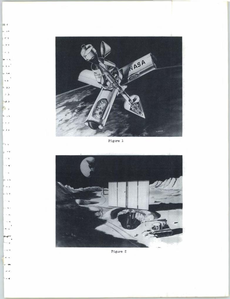
.. of kilowatts . A manned- orbiting space station (fig . 1) could require 10 to 20 kilowatts for time durations of 1 to 5 years . A permanent
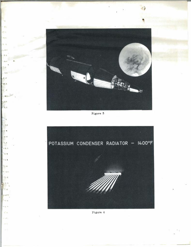
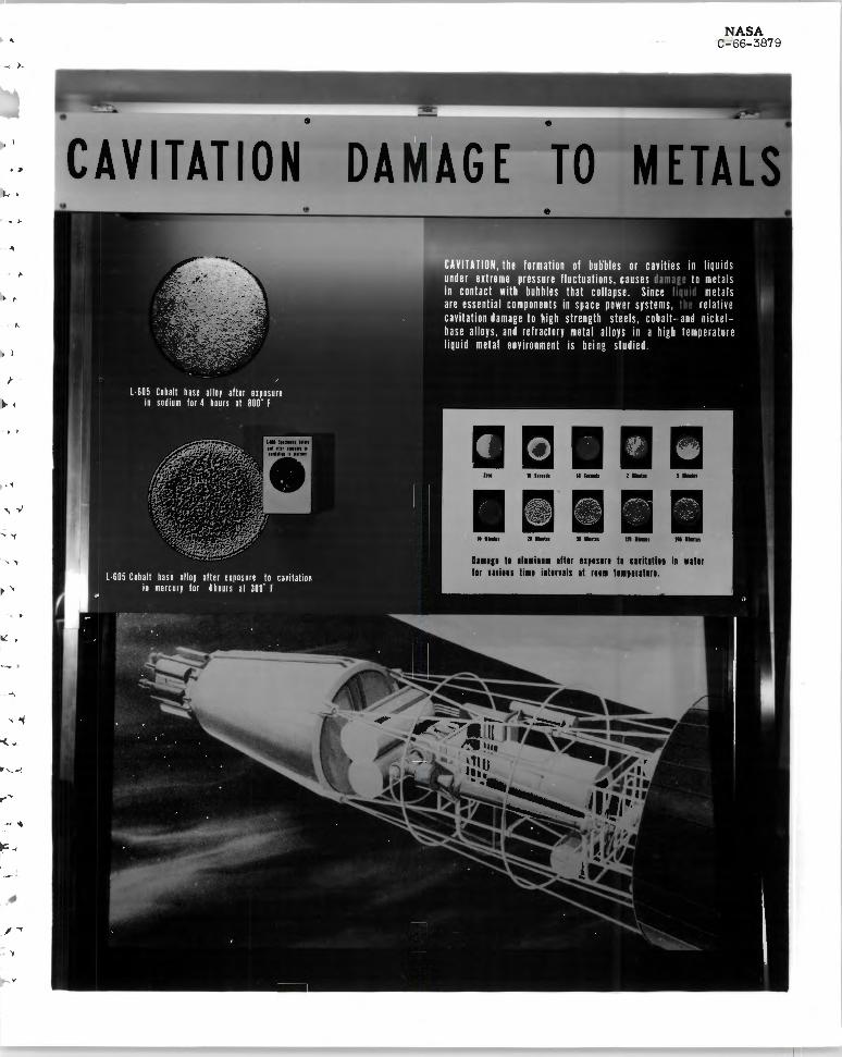
lunar base (fig . 2) could require 100 or 200 kilowatts of power for more than 1 year of operation. And, if we look into the far distant future, an interplanetary vehicle (fig . 3) which used electric propulsion rockets could require 1000 or more kilowatts of power .
At this presentation we will describe what we are doing at this Center to advance turbogenerator system technology so that these future mission power requirements can be met with compact, lightweight systems. You will tour three test facilities where turbogenerator system components are being tested.
We have under consideration two types of turbogener ator systems
the Rankine cycle system and the Brayton cycle system. The Brayton cycle system is a close- cycle gas turbine engine. It is applicable in providing power from about 2 to 100 kilowatts . Either solar or nuclear
energy can be utilized. If we use solar energy, a large mirror is
used to collect and concentrate enough sunlight to heat an energy ab
sorber . If this system ere orbiting the Earth, it would pass through
the Earth9s shadow once per orbit. The energy absorber must be de signed to store sufficient heat energy so that the system can operate
.... during the period when sunlight is absent. The energy absorber heats
- ~

.... '
• 'f
' ,. 1 ..
• >
' I
' ..
- 'I
a system operating gas such as argon up to 1500° F . This hot gas
is expanded through a turbine which drives a compressor circulating
gas around the system. The hot gas then expands through a second
turbine driving an alternator to produce the electric power. These two units we call the turbocompressor unit and the turboalternator unit. Part of the unused heat is returned to the system; the remaining heat is waste heat which is exchanged to a liquid filled loop where
it is rejected to space from a radiator .
On the stage are a few Brayton-system components . This is
an actual full-size turbine wheel, here is a compressor wheel, and
over here is an experimental compressor unit. During your test
facility tour, th~se units will be described in further detail, and you will see where· the turbocompressor and turboalternator units are
tested. This is a one-quarter scale model of a conceptual 8-kilowatt
Brayton system. In the background you see the large mirror, in the
center the power conversion unit, and around the outside, the radiator for rejecting waste:.energy.
The second type of turbogenerator system is the Rankine cycle
system. Most municipal power and light companies use the Rankine cycle for steam that is used to drive turbogenerators . In applying the Rankine cycle for use in space, we are forced to go to higher operating temperatures like 1300° to 2200° F. At these temperatures, instead of using steam we use liquid metals such as mercury or potassium. The Rankine cycle systems are higher power systems than the Brayton. They are applicable in providing power from about 20 kilowatts to 1000 or more kilowatts . A nuclear reactor is used to heat a liquid metal, which transfers energy to a boiler where mercury or
potassium is vaporized. This vapor is expanded through a turbine, driving an alternator, which generates the electric power. The vapor is liquefied, then circulated back to the boiler. To liquefy the vapor,
a liquid metal circulates through the condenser, removing waste en
ergy, which is then rejected to space from a radiator . A Rankine
2

...
.. .
' )
;- .
- >- y
...
I' T
cycle system which NASA has u.nder development is the SNAP-8 electrical generating system. It is designed to provide 35 kilowatts
of power for a little over 1 yea r of operation. The maximum cycle temperature is 1300° F, and the working fluid used is mercury.
We have on the stage a few of the SNAP-8 components. This is a full - scale model of the SNAP-8 reactor which is being developed
by the Atomic Energy Commission. The energy output of this re
actor is equivalent to the combustion of about 2 million pounds of coal. Here is a SNAP-8 mercury pump used at this point in the system to circulate mercury, and the SNAP-8 alternator which is used to generate the electric power. You will see most of the SNAP-8
components and where these components are tested together as a
system during your test facility tour. We are also advancing technology towards a higher power Rankine system, one that could pro
vide 1000 or more kilowatt s of power. In order to minimize the
size of the radiator , we are forced to go to higher cycle temperatures like up to 2200° F~ At these temperatures·, instead 'of usi~ng mercury we use a liquid metal such as potassium. We have here a two-sta ge turbine wheel which is designed to operate on potassium vapor . A unit almost identical to this recently completed 5000 hours of test time at a potassium vapor inlet temperature of 1500° F . . We are also conducting boiling and condens ing experiments using potas sium and sodium . During your t est fac ility tour , you will s ee where these exper iment s are conducted .
BRAYTON CYCLE TEST FACILITY
This fac ili y is b ing used to test the Brayton cycle turbocom
pressor and turboalternator. The facility is capable of operating at
exact Brayton cycle temperatures, pr essures, and power levels. Argon gas is cur rently being used in the facility, but mixtures of
other inert gas es will be used in the future. To aid in your understanding of this loop , its oper ation , and the arrangement of the
3

, '
l >
, I
> •
, r
, ,
equipment , we have prepared this test loop schematic. The principal pieces of equipment in this rig are an electrical heater, which is
located to your far right in a horizontal run of pipe; the facility
cooler, which is that large piece of equipment behind you; the
Brayton cycle turbocompressor, which is installed here; and the
Brayton cycle turboalternator, which has not as yet been installed
in the loop - but will be installed here.
During operation, the compressor provides pressurized argon
gas to the electric heater . The heater raises the temperature of
this gas to 1500° F and the gas then flows to the turbine. The hot
gas drives the turbine, and the exhaust from the turbine then passes to the facility cooler. The temperature of the argon gas is reduced to 76° F in the cooler, and the gas flows back to the compressor,
closing the cycle. The gas is then recycled through the loop. Currently, this facility is being used to test the Brayton cycle
turbocompressor . This is the turbocompressor with the housing
removed so that you can see some of the internal parts . These parts are the 6- inch-diameter compressor rotor, a 6-inchqiameter turbine rotor, and a common shaft which is designed to rotate at 38 500 rpm. The shaft is mounted on gas- lubricated
bearings . These bearings run on a thin film of argon gas, thinner than the thickness of a human hair. The fact that argon gas is used in the loop and also as the lubricant for the bearings eliminates the need for a separate oil lubrication system and eliminates any con
tamination problems which would be a ssociated with a separate oillubrication system.
To date, this turbocompressor has been operated satisfactorily
to a turbine- inlet temperature of 1200° F. Future tests will see this temperature raised to 1500° F .
Upon completion of the turbocompressor tests, a Brayton cycle
turboalternator will be added to the loop. This is a cross-sectional
drawing of the turboalternator showing the principal parts . They are
a turbine assembly, an alternator assembly, and, again, the gas
4

.... lubricated bearings . These two machines, incidently, are the first... to run on gas-lubricated bearings in the space power system. . .
The turboalternator is designed to deliver 8000 watts or, 8 kilowatts, of usable electric power· in space. The component parts of
'' the turboalternator, the alternator, that you see here, and the turbine, , '
are being tested separately at another Lewis facility. The objectives of this facility are to verify the design performance of the turbocom
• > pressor and the turboalternator both during startup and during longterm endurance tests . Particular attention will be paid to the per
'> formance of the gas-lubricated bearings. The results of these tests will then be used to help to predict the performance of the complete solar Brayton space power system more accurately.
,; ..
ADVANCED RANKINE TEST FACILITY
In this liquid-metal facility, we study the condensing radiator
for use in the advanced Rankine cycle space power system. To test . ., such a radiator as this on the ground, it is necessary to simulate conditions of space, namely, the low pressure and the low temperature. We do this here by placing the test radiator in this vacuum
y ,
chamber which has oil- cooled walls to dissipate the heat given off by the radiator . In operation, potassium vapor at temperatures as high as 1400° F enters the radiator at this end, and as it flows down the tubes, gives up heat which is radiated to the oil-cooled chamber
' "' walls . As the vapor looses heat, it condenses back to the liquid state and the liquid is collected at this end of the radiator where it is further cooled before being pumped back to the boiler . The boiler is lo
cated at the far end of this large enclosure on your right. This radi
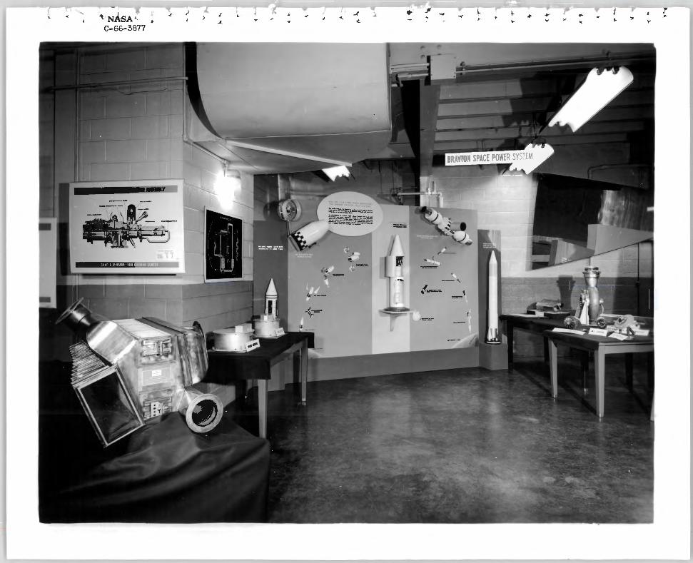
ator has operated continuously for over 300 hours, at temperatures as high as 1400° F . During operation, we photographed it through a
viewport on the far end of the vacuum chamber. On the screen behind you I have a photograph we have taken (fig. 4). The bright yellow pipe
5

at the top is the inlet manifold where the vapor is distributed to the nine tubes . The orange area covering most of the tubes is where the. . vapor is condensing and the dark red area at the bottom is where the liquid condensate is being further cooled before it is pumped back to
' . the boiler . You will notice that the condensing lengths, that is, the
orange area of the tubes, are all nearly the same. Because of this .... ;
we have concluded this radiator design and operation was successful.
As you leave this facility, you will visit a companion one where
j ... we study the boiling of the alkali metals - at present sodium. The
-< • boiler presently under test has been operated for over 900 hours
>) and i~ a single tube and shell configuration. Liquid sodium enters this tube and is boiled at temperatures as high as 2000° F . The heat , .
) source for this boiling is another stream of liquid sodium at temper. atures as high as 2200° F flowing in the annulus around the tube. Because of these high temperatures and pressures involved, the test
boiler and several other pieces of research equipment were fabri
cated from a refractory metal, columbium - 1 percent zirconium. To protect the columbium from serious oxidation at these high temperatur es, we operated the columbium components under very deep vacuum. As you walk through the facility, some of the major components you will be able to see are the electric power supply used to
' > heat the sodium initially, the vacuum equipment, the vacuum chamber of which the door has been opened so that you can see some of the columbium components inside. And, as you leave the facility, there are two large enclosures that house the service equipment used to supply sodium to the test boiler .
SNAP- 8 TEST FACILITY
What you see being assembled here in the SNAP-8 research
facility is not a flight system. It is a test rig that incorporates all of the major flight components with the exception of the nuclear reactor
6

.., T
.,
and the flight radiator. In contrast to the compact flight system, this
configuration is intentionally spread out to allow for component acces
sibility, and to accommodate instrumentation, special control devices,'.
and auxiliary fill, dump, · and filtration systems. During system operation, this entire enclosure in which we are standing is sealed and
' .. filled with dry nitrogen gas . This is a precaution against fire hazards due to accidental spillage of highly reactive liquid metals used in this system.
In this system we have the three basic loops of the SNAP-8 system. In the primary loop, this 650-kilowatt electric heater together
,, with an analog computer, which controls its power, approximate the
, > behavior of the flight reactor . A flight prototype pump circulates the liquid-metal fluid, which transfers energy from the heater to this flight design boiler . In the secondary loop, mercury vapor leaving the boiler at a temperature of 1275° F and a pressure of 27 5 pounds per square inch drives this turboalternator assembly, producing 35 kilowatts of usable electricity. Turbine exhaust is liquefied in the condenser, again a flight component, and is returned to the boiler<.., by this mercury pump. A third liquid-metal loop transfers the waste
heat from the condenser to the simulated radiator components located , '
in the two tanks at the rear of the cell.
During the past year, a workhorse system was operated in this• ' >
facility . At that time we studied basic control requirements, solved problems associated with system operation, and developed the reactor and radiator simulators used in the present system. Test objectives for this system include dynamic and control studies, evaluation of system performance, and realistic startup investigations. The equipment associated with data acquisition and system control,
as well as the analog computer used in the reactor and radiator sim
ulators, is located in the remote control room. In the static display area you will have a chance to examine a one
quarter scale model of a proposed flight configuration.
7
, l
' ,
...
J.
J >
, '
> '
, "
) >
Figure 2
-
,
Figure 3
Figure 4

y •
. . .. l
..
, . )A I
.. )
~
" . '"
' .'
' .
• <


' . .... . .' .
-. ' . -
I
> •
_,,,
0 ... .,co <~
(/) I
"'<~
Za u
.. ~

- -
• ' J..
... ,
......
->
llllllCllYE SlllCEr
lllclu1 1diat1t1 l1ttclln lrn11d ild h•ncilld ill th Luu Inure• Cnttr 111 si•Jlu, hn hllu 11nl1li11 th• unut11ul ni1titlah11 •111ctus. ad in htHlll •iltlr ml i1 ht• sJm ad lil•mtu1 11,ui1uts. n1s l11nstr11111 shu t1111111 11 th SHI 1dinchu mm •1 ht• 1011 1t htectm
Th •1t1et11 11 •Jtrillill hs n H1111ulll JUtl. llllr II mnls 11 iltt1..lati11, Ot 111111 nalym will •isJIO lh emu OtClfH II th 1diuctin SHIU. NIU 1•11 1•1 se1ic11•1clu IJICllH hs 1111.. llm .
ms i••iutu 111• nuu 11ul11i11.
. fA 8 RI CA JI 0 N Th slt•·•pltJ n•11m, t1111h1" wiO lh •nitt ill th CllllSJH.111 sh1u. is ShH hlH Th lHIS ellut hs 1e"1u• t•1cl11 f1t1ctus On m u1111mll1 111111•11
..... .
NASA C-66-3868'

I •
->
' .

••
...
I '
I>
.~ '
.... '
,_
NASA C- 66- 3879
- >
CAVITATION DAM AG •
··- ·- ·- ·
111111 II llllilll 11111 llJHlll II CllillliH ii 11111 Ill mills 1111 illllHIS II IHI lllJlllllll.
-.
...
.'
'I.,/
' .
I ,


.....
"' >
,}

·~
'
--..

•..J
-. ~.. '.
" .
-y
..,. .
..