rotor failures diagnosis of squirrel cage induction motors
TRANSCRIPT

Journal of Electrical Engineering & Technology Vol. 4, No. 2, pp. 219~228, 2009 219
Rotor Failures Diagnosis of Squirrel Cage Induction Motors with Different Supplying Sources
Arezki Menacer*,**, Gérard Champenois**, Mohamed Said Naît Saïd***, Abdelhamid Benakcha*, Sandrine Moreau** and Said Hassaine****
Abstract – The growing application and the numerous qualities of induction motors (IM) in industrial processes that require high security and reliability levels has led to the development of multiple meth-ods for early fault detection. However, various faults can occur, such as stator short-circuits and rotor failures. Traditionally the diagnosis machine is done through a sinusoidal power supply, in the present paper we study experimentally the effects of the rotor failures, such as broken rotor bars in function of the ac supplying, the load and show the impact of the converter from diagnosis of the machine. The technique diagnosis used is based on the spectral analysis of stator currents or stator voltages respectively accord-ing to the types of induction motor ac supplying. So, four different ac supplying are considered: ◉ the IM is directly by the balanced three-phase network voltage source, ◉ the IM is fed by a sinusoidal current source given the controlled by hysteresis, ◉ the IM is fed (in open loop) by a scalar control imposing through ratio V/f=constant, ◉ the IM is controlled through a vector control using space vector pulse width modulation (SVPWM)
technique inverter with an outer speed loop.
Keywords: Squirrel cage induction motor, SVPWM, DSP, Supply, Diagnosis, Broken rotor bars, Fault detection, Fourier analysis
1. Introduction The applications of induction motors are widespread.
Some are key elements in assuring the continuity of the process and production chains of many industries. The list of the applications take place in industries related to elec-tricity, mining, petrochemical products and domestic appli-ances. Induction motors are often used in critical applica-tions such as nuclear plants, as well as aerospace and mili-tary applications, where the reliability is important. The induction motors must be used in hostile environments such as corrosive and dusty places. They are also exposed to a variety of undesirable conditions and situations such as incorrect operations. These unwanted conditions can cause the induction motor to go into a failure period, which may result in an unserviceable condition of the motor.
As other rotating machines, electric motors are not available at all times because several electric machine components can be affected by failures. So, since last dec-ade, many research studies were carried out on rotor bar faults and on the development of diagnosis techniques ap-plied to three-phase squirrel-cage induction machines [1-5].
Among rotor defects, the break of rotor bars or of an
end ring portion may occur. The problem researchers is that direct measurement of rotor variables is not possible for a squirrel-cage induction motor.
The developed diagnosis strategy relies on the stator currents or voltages monitoring and is based here on the spectral analysis of rotor defects signatures so as to detect early failure. Only the case of rotor broken bars is studied in the present paper.
This diagnosis method is very advantageous thanks to its non-invasive properties. From the analysis of the defects signatures, the stop of the production process line, where the induction motor is used, can be programmed to replace the failing element before the breakdown becomes very serious and may yield causing dramatic consequences an the industrial process [6, 7].
2. Space vector pulse width modulation (SVPWM) A three-phase voltage source PWM inverter system is
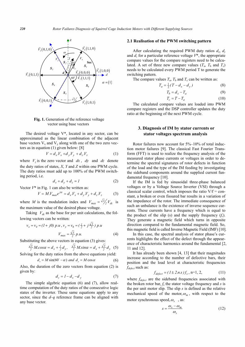
shown in Fig. 1. For the three phases inverter, there are eight combinations (vectors) of the ON and OFF states of the in-verter switches S1 to S6.
Six of these eight are non-zero base vectors (V1 toV6) and are shown in Fig. 1. Two other vectors not shown in the figure are V0 and V7, are the zero vectors corresponding to states 0 (0 0 0) and 7 (1 1 1) of the switching variables. The base vectors divide the cycle into six (60° wide sectors). Let us assume that an arbitrary voltage V* is to be generated by the inverter.
* LGEB Laboratory of Electrical Engineering of Biskra, Algeria, ** LAII Laboratory of Automatic and Industrial data processing,
University of Poitiers, France, *** LSPIE Laboratory of Induction systems, Electromagnetic Propul-
sion of Batna, Algeria, **** Electrical Engineering University of Tiaret, Algeria. Received 8 September 2008; Accepted 10 April 2009
Rotor Failures Diagnosis of Squirrel Cage Induction Motors with Different Supplying Sources 220
Fig. 1. Generation of the reference voltage vector using base vectors
The desired voltage V*, located in any sector, can be
approximated as the linear combination of the adjacent base vectors Vx and Vy along with one of the two zero vec-tors as in equation (1) given below: [8]
zzyyxx V.dV.dV.dV ++= (1)
where zV is the zero vector and dx , dy and dz denote the duty ratios of states, X, Y and Z within one PWM cycle. The duty ratios must add up to 100% of the PWM switch-ing period, i.e.
1ddd zyx =++ (2) Vector V* in Fig. 1 can also be written as:
zzyyxxj
max V.dV.dV.deV.MV ++== α (3)
where M is the modulation index and dc23
max VV = is the maximum value of the desired phase voltage.
Taking dcV as the base for per unit calculations, the fol-lowing vectors can be written:
p.u j0) (1 v v 4x +== , p.u )j ( v v 23
21
6y +==
p.u.V 23
max = (4) Substituting the above vectors in equation (3) gives:
y23
x23
y21
x23 ddM.sin,ddM.cos +=+= αα (5)
Solving for the duty ratios from the above equations yield: sin(60 ) cosx yd M and d Mα α= − = (6)
Also, the duration of the zero vectors from equation (2) is given by:
yxz dd1d −−= (7) The simple algebric equation (6) and (7), allow real-
time computation of the duty ratios of the consecutive logic states of the inverter. These same equations apply to any sector, since the d–q reference frame can be aligned with any base vector.
2.1 Realisation of the PWM switching pattern After calculating the required PWM duty ratios dx, dy
and dz for a particular reference voltage V*, the appropriate compare values for the compare registers need to be calcu-lated. A set of three new compare values (Ta, Tb and Tc) needs to be calculated every PWM period T to generate the switching pattern.
The compare values Ta, Tb and Tc can be written as: )ddT(T yxa −−= 2
1 (8)
axb TdT −= (9)
ac TTT −= (10) The calculated compare values are loaded into PWM
compare registers and the DSP controller updates the duty ratio at the beginning of the next PWM cycle.
3. Diagnosis of IM by stator currents or stator voltages spectrum analysis
Rotor failures now account for 5%–10% of total induc-
tion motor failures [9]. The classical Fast Fourier Trans-form (FFT) is used to realize the frequency analysis of the measured stator phase currents or voltages in order to de-termine the spectral signatures of rotor defects in function of the load and the type of the IM feeding by investigating the sideband components around the supplied current fun-damental frequency [10].
If the IM is fed by sinusoidal three-phase balanced voltages or by a Voltage Source Inverter (VSI) through a classical scalar control, which imposes the ratio V/f = con-stant, a broken or even fissured bar results in a variation of the impedance of the rotor. The immediate consequence of such an unbalance is the existence of inverse sequence cur-rents. These currents have a frequency which is equal to the product of the slip (s) and the supply frequency (fs). They generate a magnetic field which turns in opposite direction compared to the fundamental magnetic field. So, this magnetic field is called Inverse Magnetic Field (IMF) [10].
In this case, the spectral analysis of stator phase’s cur-rents highlights the effect of the defect through the appear-ance of characteristic harmonics around the fundamental [2, 11 and 12].
It has already been shown [4, 13] that their magnitudes increase according to the number of defective bars, their position and the load level at characteristic frequencies fdefect such as:
sdefect f)s.n.21(f ±= , n=1, 2, (11) where fdefect are the sideband frequencies associated with the broken rotor bar, fs the stator voltage frequency and s is the per unit motor slip. The slip s is defined as the relative mechanical speed of the motor, mω , with respect to the motor synchronous speed, sω , as:
s
mssω
ωω −= (12)
( )6 1,1,0V
( )4 1,0,0V
( )2 0,1,0V
( )3 0,1,1V
( )1 0,0,1V ( )5 1,0,1V
( )1α ≡
I
( )0 0,0,0V( )7 1,1,1V
d
q
yV xV
xd
yd
ω
1S2S
3S
4S
5S
6S
60
Sec
23−
α
Arezki Menacer, Gérard Champenois, Mohamed Said Naît Saïd, Abdelhamid Benakcha, Sandrine Moreau and Said Hassaine 221
On the other hand, if the IM is supplied by sinusoidal threes phases balanced currents by a converter controlled for instance by hysteresis, the magnitude and the shape of the currents are imposed to the IM in this case and the con-sequence of a broken rotor bar results this time in the exis-tence of inverse sequence voltages. These voltages have a frequency which is equal to the product of the slip (s) and the current supply frequency (fs).
The experimental results presented in the next section will confirm the need for adapting the diagnosis strategy of the rotor defects according to different supplies types of the induction machine. Indeed in function of the supplies type of the induction machine, the spectral analysis has to be applied to the phase currents and/or to the phase voltage.
In each case, the spectral analysis of the rotor speed will also be given so as to evaluate and compare with each other the impact of the same rotor default on mechanical variables in function of the feeding type [14].
4. Experimental diagnosis of broken rotor bars for three different induction machine feedings
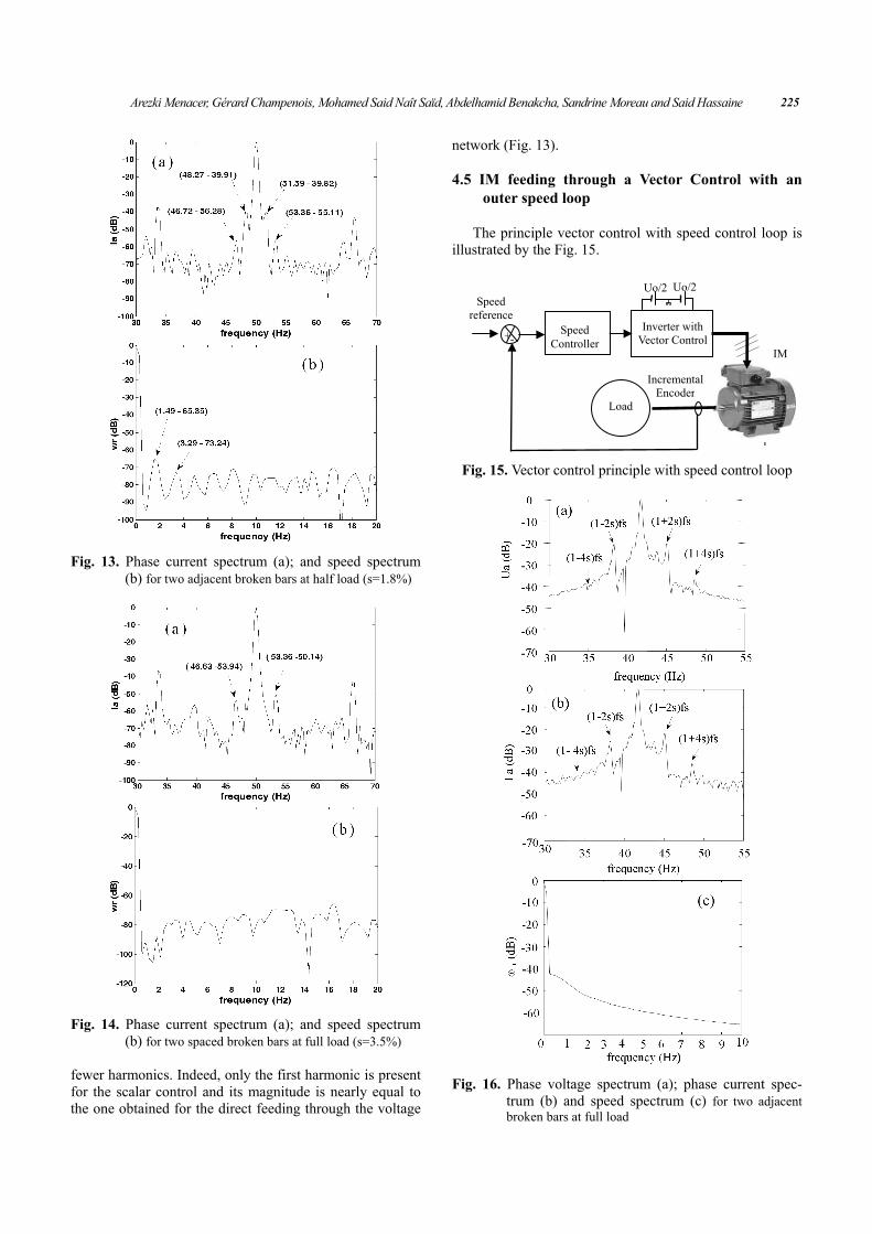
4.1 Presentation of the experimental test bench The experimental set-up used in this study is shown on
Fig. 1. It consists of a 1.1 kW (LS 90 Leroy Somer), 220V, 50Hz, 2 poles pair squirrel cage induction machine.
The induction machine has been designed and con-structed in order to simulate true faulty experiments. Dif-ferent rotors, with broken bars, are used to simulate a bar breakage occurring during operation.
The different control strategies of the IM are imple-mented on a dSPACE card 1104 based on Motorola Power PC 603e processor (250 MHz) and Texas Instruments’ TMS 320F240 DSP (20 MHz) under Simulink/Matlab® environment. An incremental encoder of 1024 PPR is used to obtain the rotor speed measurement. And the data acqui-sition system has a sampling period equal to Te = 0.1ms and the measured variables (phase voltages and phase cur-rents) are passed through a 4th order Butterworth filter whose cut-off frequency is 500 Hz.
Fig. 2. The experimental test bench
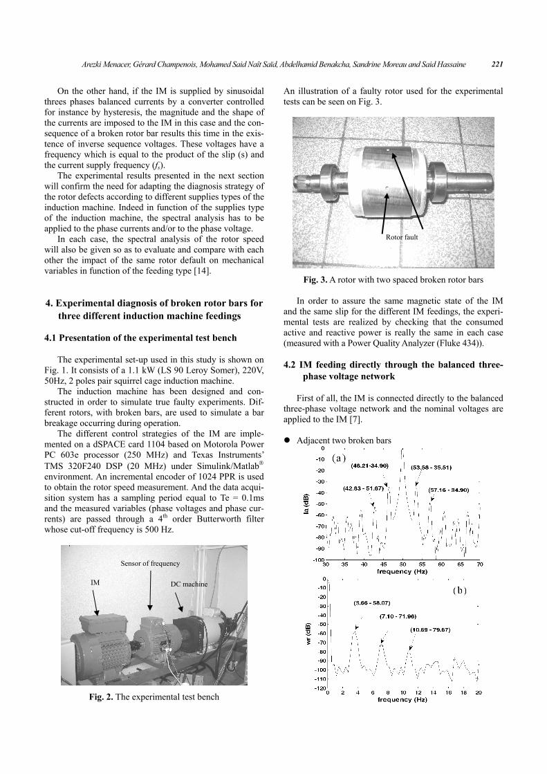
An illustration of a faulty rotor used for the experimental tests can be seen on Fig. 3.
Fig. 3. A rotor with two spaced broken rotor bars
In order to assure the same magnetic state of the IM
and the same slip for the different IM feedings, the experi-mental tests are realized by checking that the consumed active and reactive power is really the same in each case (measured with a Power Quality Analyzer (Fluke 434)).
4.2 IM feeding directly through the balanced three-
phase voltage network First of all, the IM is connected directly to the balanced
three-phase voltage network and the nominal voltages are applied to the IM [7].
Adjacent two broken bars
DC machine IM
Sensor of frequency
Rotor fault

Rotor Failures Diagnosis of Squirrel Cage Induction Motors with Different Supplying Sources 222
Fig. 4. Stator current spectrum and speed spectrum
for two adjacent broken bars a, b) at full load (s=3.72%) c, d) at half load (s=1.77%)
From Fig. 4, we notice the appearance of harmonics on
the normalized (in respect with the fundamental compo-nent) phase current spectrum. These harmonics have mag-nitude which increases according to the rise of the load level [11-14].
The frequencies values of characteristic harmonics of rotor defects given by the equation (11) and those deduced from the spectrum graphs (a) and (c) are in agreement with one another.
From graphs (b) and (d), it can be noticed through the normalized speed spectrum that harmonics around the slip frequency (and its multiples) appear. So, broken rotor bars produces mechanical disturbances, which increase with the load. At full load, the magnitude of the first speed har-monic at the slip frequency is about -58 dB, whereas it is about -65 dB at half load.
Spaced two broken bars
Fig. 5. Stator current spectrum and speed for two spaced broken bars a, b) at full load (g=3.22%) c, d) at half load (g=1.77%)
When the two broken bars are spaced, the magnitude of
current harmonics is reduced compared to the two adjacent broken bars and the speed harmonics are reduced as well (Fig. 5).
4.3 IM feeding through a current converter con-
trolled by hysteresis The principle of the induction machine feeding through
a current converter controlled by hysteresis is given on Fig.6.
The magnitude of the three phase’s currents is main-tained constant and the current frequency may vary.
The graph (a) of the Fig. 7 shows that the phase current is sinusoidal and in this case it turns out that phase voltage is disturbed by the broken rotor bars. Indeed, it appears on

Arezki Menacer, Gérard Champenois, Mohamed Said Naît Saïd, Abdelhamid Benakcha, Sandrine Moreau and Said Hassaine 223
graph (b) the characteristic harmonics of the rotor defect on the voltage spectrum and their magnitude is similar to the current harmonics obtained for the direct voltage network feeding.
Fig. 6. IM fed by current converter controlled by hysteresis
Fig. 7. Phase current spectrum (a); phase voltage spectrum
(b) and speed spectrum (c) for two adjacent broken bars at full load (s=3.52%) a) stator current , b) stator voltage c) rotor speed
From the speed spectrum given on graph (c), it can be deduced that rotor speed is disturbed by the two adjacent rotor broken bars on the same way for an IM feeding through the current converter or directly through the volt-age network.
Fig. 8. Phase voltage spectrum (a) and speed spectrum (b)
for two adjacent broken bars at half load (s=1.76%)
Fig. 9. Phase voltage spectrum and speed spectrum for
spaced two broken bars at full load (s= 3.5%)
tsinω
I
2 Uo
2 Uo
+
no
S1 S2 S3
S4 S5 S6
Va Vb Vc
*cI
*aI
*bI
)(sin 32π+ωt
)(sin 32 π−ωt
refI
Ia
Ic
IM
Load
Ib

Rotor Failures Diagnosis of Squirrel Cage Induction Motors with Different Supplying Sources 224
At half load, the effect of the two adjacent broken bars is less visible on the voltage spectrum and the speed is also less disturbed by the rotor defect. Now, if two spaced bro-ken rotor bars are considered, Fig. 9 shows that the rotor defect is once more less visible on the phase voltage spec-trum than for the two adjacent broken bars and at this time the rotor speed is not affected by the defect, even if the IM is at full load.
For a Current Source Inverter, the diagnosis of broken rotor bars has to be realised through the spectral analysis of stator phase voltages, which highlights the effect of the defect thanks to the appearance of the characteristic har-monics around the fundamental.
The experimental results show that the impact of the same rotor default at the same load level on mechanical variables is nearly the same if the IM is fed by a current converter controlled by hysteresis or if the IM is fed di-rectly through the voltage network.
4.4 IM feeding through a Scalar Control (in open
loop) with V/f=constant The V/f control, which is realised with a low cost and
simple design, is advantageous in the middle to high-
Fig. 10. Scalar control principle (V/f=cste) of the IM
Fig. 11. Control signals generated by SVPWM
speed range. Its torque response depends on the electrical time constant of the motor, and adjustments of the control parame-ters are not needed. V/f control is the best choice for simple variable speed applications like fans the pumps and it is the more effective control in the high-speed range [15, 16].
The scalar control principle is illustrated on Fig. 10 and the SVPWM signals are shown on Fig. 11.
The experimental results of the diagnosis of two broken rotor bars when the IM is fed by a classical Scalar Control (imposing the ratio V/f=constant) are given below (Fig. 12, 13 and 14).
Fig. 12. Phase current spectrum (a); phase voltage spectrum
(b) and speed spectrum (c) for two adjacent bro-ken bars at full load (s=3.53%)
The obtained current and voltage spectrums are very
similar to those obtained for a direct feeding to the voltage network. As for the speed spectrum presented on Fig. 12 (c), the comparison with Fig. 4 (b) shows that it contains
f V
ref
Vb
2 Uo
2 Uo
+
nIb
Ia
S1 S2 S3
Va Vc
S4 S5 S6
Space vector
modulation
Va*
Vb*
Vc*
V
f
f
IM
Load
Ic
Arezki Menacer, Gérard Champenois, Mohamed Said Naît Saïd, Abdelhamid Benakcha, Sandrine Moreau and Said Hassaine 225
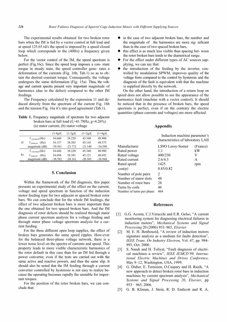
Fig. 13. Phase current spectrum (a); and speed spectrum (b) for two adjacent broken bars at half load (s=1.8%)
Fig. 14. Phase current spectrum (a); and speed spectrum (b) for two spaced broken bars at full load (s=3.5%)
fewer harmonics. Indeed, only the first harmonic is present for the scalar control and its magnitude is nearly equal to the one obtained for the direct feeding through the voltage
network (Fig. 13).
4.5 IM feeding through a Vector Control with an outer speed loop
The principle vector control with speed control loop is
illustrated by the Fig. 15.
Fig. 15. Vector control principle with speed control loop
Fig. 16. Phase voltage spectrum (a); phase current spec-
trum (b) and speed spectrum (c) for two adjacent broken bars at full load
Speed Controller
Load
IM
Incremental Encoder
Speed reference
Uo/2 Uo/2
-+Inverter with
Vector Control
Rotor Failures Diagnosis of Squirrel Cage Induction Motors with Different Supplying Sources 226
The experimental results obtained for two broken rotor bars when the IM is fed by a vector control at full load and at speed 125.65 rd/s the speed is imposed by a speed closed loop which corresponds to the (40Hz) a frequency given below.
For the vector control of the IM, the speed spectrum is perfect (Fig.16c). Since the speed loop imposes a con- stant torque in steady state, the speed controller gene- rates a deformation of the currents (Fig. 16b, Tab.1) so as to ob-tain the desired constant torque. Consequently, the voltage undergoes the same deformation (Fig. 15a). Thus, the volt-age and current spectra present very important magnitude of harmonics (due to the defect) compared to the other IM feedings.
The Frequency calculated by the expression 11 and de-duced directly from the spectrum of the current Fig. 16b and the tension Fig. 16a it’s into good agreement (Tab.1).
Table 1. Frequency magnitude of spectrum for two adjacent
broken bars at full load (fs=41.78Hz, g=4.26%) (a) stator current, (b) stator voltage
(1-4g)fs (1-2g)fs (1+2g)fs (1+4g)fs
f calculated (Hz) 34.660 38.220 45.340 48.900 f deduced (Hz) 34.157 38.285 45.145 48.575 a)
magnitude (dB) -39.561 -23.772 -21.140 -34.590f calculated (Hz) 34.660 38.220 45.340 48.900 f deduced (Hz) 34.694 38.381 45.121 48.692 b)
magnitude (dB) -38.582 -20.161 -20.365 -36.944
5. Conclusion Within the framework of the IM diagnosis, this paper
presents an experimental study of the effect on the current, voltage and speed spectrum in function of the induction motor feeding type for two adjacent or spaced broken rotor bars. We can conclude that for the whole IM feedings, the effect of two adjacent broken bars is more important than the one obtained for two spaced broken bars. And the IM diagnosis of rotor defects should be realized through stator phase current spectrum analysis for a voltage feeding and through stator phase voltage spectrum analysis for a cur-rent feeding.
For the three different open loop supplies, the effect of broken bars generates the same speed ripples. How-ever for the balanced three-phase voltage network, there is a lower noise level on the spectra of currents and speed. This property leads to more visible characteristic harmonics of the rotor default in this case than for an IM fed through a power converter, even if the tests are carried out with the same active and reactive powers, and thus the same slip. It should also be noted that the IM feeding through a current converter controlled by hysteresis is not easy to realize be-cause the operating becomes rapidly the unstable for impor-tant torques.
For the position of the rotor broken bars, we can con-clude that:
in the case of two adjacent broken bars, the number and the magnitude of the harmonics are more sig- nificant than in the case of two spaced broken bars,
this effect is as much less visible than spacing bet- ween the rotor broken bars tends to the diametrical range.
For the effect under different types of AC sources sup-plying, we can say that:
the introduction of the feeding by the inverter, con- trolled by modulation SPWM, improves quality of the voltage form compared to the control by hysteresis and the diagnosis of the fault is equivalent with that the machine is supplied directly by the network. On the other hand, the introduction of a return loop on
speed does not allow possible to see the appearance of the harmonics fault (machine with a vector control). It should be noticed that in the presence of broken bars, the speed spectrum is perfect, even if on the contrary the electric quantities (phase currents and voltages) are more affected.
Appendix
Induction machine parameter’s characteristics of laboratory LAII
Manufacturer LS9O Leroy-Somer (France) Rated power 1.1 kW Rated voltage 400/230 V Rated current 2.6/4.3 A Rated speed 1425 rpm
)cos(ϕ 0.85/0.82 Number of pole pairs 2 Number of stator slots 48 Number of rotor bars 28 Turns by coils 46 Number of turns per phase 464
References
[1] G.G. Acosta, C.J.Verucchi and E.R. Gelso, “A current monitoring system for diagnosing electrical failures in induction motors”, Mechanical Systems and Signal Processing 20 (2006) 953–965, Elsevier
[2] M. E. H. Benbouzid, “A review of induction motors signature analysis as a medium for faults detection”, IEEE Trans. On Industry Electron, Vol. 47, pp. 984-993, Oct. 2000.
[3] S. Nandi and H. Toliyat, “Fault diagnosis of electri-cal machines–a review”, IEEE IEMCD’99, Interna-tional Electric Machines and Drives Conference, May 9–12, Washington, USA, 1999.
[4] G. Didier, E. Ternisien, O.Caspary and H. Razik, “A new approach to detect broken rotor bars in induction machines by current spectrum analysis”, Mechanical Systems and Signal Processing 20, Elsevier, pp 953– 965, 2006.
[5] G. B. Kliman, J. Stein, R. D. Endicott and R. A.
Arezki Menacer, Gérard Champenois, Mohamed Said Naît Saïd, Abdelhamid Benakcha, Sandrine Moreau and Said Hassaine 227
Koegl “Non invasive detection of broken rotor bars in operating inductions motors”, IEEE Transactions on Energy Conversion, Vol. 3(4), Dec 1998.
[6] D.J Siyambalapitiya and P.G. MClaren, “Reliability improvement and economic benefits of on-line moni-toring system for large induction machines”, IEEE Transactions on Industry Applications 26, pp 1018–1025, 1990.
[7] A. Menacer, “Contribution à l'identification des paramètres et des états d'une machine à induction pour diagnostic et développement de commande robuste”, thèse doctorat, université de Batna, Algérie, Dec 2007.
[8] F.Filipetti, “G. Franceschini, C. Tassoni and G. B. Kliman, Impact of speed ripple on rotor fault diagnosis of induction machine”, International Conference on Electrical Machines, Vol.2, Vigo, Spain, Sept 10-12, 1996.
[9] H. Bae, Y. Tae Kim, S.H. Lee, S. Kim, and M.H.
Lee, “Fault diagnostic of induction motors for equipment reliability and health maintenance based upon Fourier and wavelet analysis”, Artif Life Ro-botics (2005) 9:112–116
[10] J.W. Cooley, P.A. W. Lewis and P.D. Welch, “Ap-plication of the fast Fourier transform to computa-tion of Fourier integrals, Fourier series and convolu-tion integrals”, IEEE Transactions on Audio and Electroacoustics, Vol. AU-15(2), pp. 79-84, 1967
[11] A. Menacer, S. Moreau, A. Benakcha and M.S. Nait Said, “Effect of the position and the number of bro-ken bars on Asynchronous Motor Stator Current Spectrum”, EPE-Power Electronics and Motion Control, Portoroz, Slovenia, 2006
[12] A. Menacer, M.S. Nait Said, A. Benakcha, and S. Drid, “Stator current analysis of incipient fault into asynchronous motor bars using Fourier fast trans-form”, Journal of Electrical Engineering, Roumanie, Vol 4, N°2-2004, pp 5-12.
[13] G. Didier, “Modélisation et diagnostic de la machine asynchrone en présence de défaillance”, Thèse de Doctorat de l’Université Henri Poincaré, Nancy-I, 2004.
[14] W. Shireen, S. Vanapalli and H. Neneb, “DSP based inverter control for alternate energy systems”, Journal of Power Sources 166 (2007) 445–449, El-sevier.
[15] A. Menacer, S. Moreau, G. Champenois, A. Benak-cha and M.S. Nait Said, “Rotor Failures Diagnosis of Induction Machines by Current or Voltage Spec-trum Analysis in Function of the Type of Feeding and the Load”, IET, Colloquium On Reability in Electromagnetic Systems. Preliminary May 2007, Paris, France.
[16] S.V. Ustun and M. Demirtas, “Optimal tuning of PI coefficients by using fuzzy-genetic for V/f con-trolled induction motor”, Expert Systems with Ap-plications, (2007), Elsevier.
Menacer Arezki was born in Batna, Algeria, in 1968. He receives the B.Sc. degree in electrical engineering from the University of Batna, Algeria, in 1992, and the M.Sc. degree in electrical control from the Electrical Engineering Institute of Biskra University, Algeria, in 1996. He receives the Ph.D. degree
in electrical control from the University of Batna and LAII Laboratory of Automatic and Industrial data processing, University of Poitiers, France, in 2007 and the “habilitation degree” in 2009 from University of Biskra Algeria. Cur-rently, he is a Teaching Assistant with the Electrical Engi-neering Institute at the University of Biskra and member of LGEB Laboratory of Electrical Engineering of Biskra, Al-geria. His major fields of interest in research are diagnosis, identification and control of electrical machines ([email protected]).
Gérard Champenois was born in France in 1957. He receives the Ph.D. degree in 1984 and the “habilitation degree” in 1992 from the Institut Na-tional Polytechnique de Grenoble (France). Now he is professor at the University of Poitiers (France). His major fields of interest in research are electrical machines
associated with static converter; control, modelling and diagnosis by parameter identification techniques and neural network. ([email protected])
Mohamed-Saïd Naït-Saïd was born in Batna, Algeria, in 1958. He receives the B.Sc. degree in Electrical Engineering from the National Polytechnic Institute of Algiers, Algeria, in 1983, and the M.Sc. degree in Electrical and Com-puter Engineering from Electrical En-gineering Institute of Constantine Uni-
versity, Algeria, in 1992. He received the Ph.D. degree in Electrical and Computer Engineering from University of Batna in collaboration with Picardie Jules Verne Univer-sity (France), in 1999. Currently, he is a full Professor at the Electrical Engineering Institute of Batna University. He was the first head of the first scientific laboratory in Batna University, Laboratory of Induction and Propulsion Induc-tion Machine Electromagnetic Systems ‘LSPIE’. LSPIE-Lab has been well evaluated from 2000-2009 by the high education Algerian ministry. The research interests include electric machines and drives control and diagnosis. In this research area, Dr. Naït-Saïd has supervised about eight Ph.D. thesis and more than twenty M.sc. thesis from which many scientific papers has been published ([email protected]).
Rotor Failures Diagnosis of Squirrel Cage Induction Motors with Different Supplying Sources 228
Benakcha A/Hamid was born in 1961 in Arris, Algeria. He had achieved a M.sc. in 1980 and a B.Sc. in 1983 from the University of Batna, Algeria, and a Master of Science in 1985 and a Ph.D. in electronics from the University of Clermont-Ferrand, France. Since 1991, he teaches at the University of Biskra,
Algeria. He is member of the Research Laboratory of elec-trotechnic of Biskra and the head of the research group: Simulation of sliding mode control of an asynchronous machine. His other research interests are: Electric ma-chines (design, modelling, identification, control), power electronics, electromagnetism (antennas, free propagation), electronics (television). ([email protected])
Sandrine MOREAU was born in France in 1972. She received the Ph.D. degree from the University of Poitiers in automatic control in 1999. She is now Assistant Professor at the University of Poitiers (France). Her major research interests are modelling, identification, diagnosis and control of electrical ma-
chines associated with static converters. ([email protected])
Said HASSAINE was born in Tiaret, Algeria. He receives the B.Sc. degree in the electrical and electronic engi-neering degree from the University of Tiaret in 1992. He receives the Ph.D. degree in electrical control from the University of Oran and LAII Labora-tory of Automatic and Industrial data
processing, University of Poitiers, France, in 2008. Cur-rently he prepares an habilitation at the University of Tiaret, Algeria. His main research area is on application of new robust control techniques of the permanent magnet syn-chronous machine. ([email protected]).