round head framing nailer - lowes...
TRANSCRIPT

1 - ENG FR350B
ROUND HEAD FRAMING NAILER
Cloueuse de charpente à clous à tête ronde
Clavadora para estructuras con cabezal redondo
www.portercable.com
INSTRUCTIVO DE OPERACIÓN, CENTROS DE SERVICIO Y PÓLIZA DE GARANTÍA.
LÉASE ESTE INSTRUCTIVO ANTES DE USAR EL PRODUCTO.
Française: Page 17Español: Página 34
Instruction manualManuel d'instructionsManual de'instrucciones
9R195763RA

2 - ENG
• Actuating tool may result in flying debris, collationmaterial, or dust which could harm operator’s eyes.OperatorandothersinworkareaMUSTwearsafetyglasses with side shields. These safety glasses must conform to ANSI Z87.1 requirements (approved glases have “Z87” printed or stamped on them). It is the employer’s responsibility to enforce the use of eye protection equipment by the tool operator and other people in the work area. (Fig. A)
• Minimize flying dust and debris by rotating 360˚exhausttoappropriatesetting.
• Alwayswearappropriatepersonalhearingandotherprotection during use. Under some conditions anddurationofuse,noisefromthisproductmaycontributetohearingloss.(Fig. A)
• Useonlyclean,dry,regulatedair.Condensationfromanaircompressorcanrustanddamagethe internalworkingsofthetool.(Fig. B)
• Regulate air pressure. Use air pressure compatiblewith ratings on the nameplate of the tool. [Not to exceed 120 psi (8.3 bar).] Do not connect the tool to a compressor rated at over 175 psi. The tool operating pressure must never exceed 175 psi even in the event of regulator failure. (Fig. C)
• Only use an air hose that is rated for a maximumworking pressure of at least 150 psi (10.3 bar) or150%ofthemaximumsystempressure,whicheverisgreater.(Fig. D)
70 psi
4.9 bar
Fig.C
Fig.B
Fig.A
Fig.D
IMpORTAnTSAFeTyInSTRUCTIOnSFORpneUMATICTOOlS
save these instructionsWhen using any pneumatic tool, all safety precautions, as outlined
below, should be followed to avoid the risk of death or serious injury. Read and understand all instructions before operating the tool.
DeFInITIOnS-SAFeTyGUIDelIneS
The definitions below describe the level of severity for each signal word. Please read the manual and pay attention to these symbols.
Indicates an imminently hazardous situation which, if not avoided, willresult in deathorseriousinjury.
Indicates a potentially hazardous situation which, if not avoided, could result in deathorseriousinjury.
Indicates a potentially haz ard ous situation which, if not avoided, mayresult in minorormoderateinjury.
Used without the safety alert symbol indicates a situation which, if not avoided,may result inpropertydamage.

3 - ENG
• Do not use bottled gases to power this tool. Bottledcompressed gases such as oxygen, carbon dioxide,nitrogen,hydrogen,propane,acetyleneorair arenotfor use with pneumatic tools. Never use combustible gases or any other reactive gas as a power source for this tool. Danger of explosion and/or serious personal injury may result. (Fig. E)
• Usecouplings that relieveallpressure from the toolwhen it is disconnected from the power supply.Use hose connectors that shut off air supply from compressorwhenthetoolisdisconnected.(Fig. F)
• Disconnect tool from air supply when not in use.Always disconnect tool from air supply and removefasteners from magazine before leaving the area orpassing the tool to another operator. Do not carrytooltoanotherworkareainwhichchanginglocationinvolves theuseof scaffoldings, stairs, ladders, andthe like, with air supply connected. Do not makeadjustments,removemagazine,performmaintenanceor clear jammed fasteners while connected to theair supply. If the contact trip is adjusted when the tool is connected to the air supply and nails are loaded, accidental discharge may occur. (Fig. G)
• Connect tool to air supply before loading fastenerstopreventanunintentionalfastenerdischargeduringconnection. The tool driving mechanism may cyclewhen the tool is connected to the air supply. Do not load fasteners with the trigger or the contact trip depressed to prevent unintentional driving.
• Donotremove,tamperwith,orotherwisecausethetool, trigger, or contact trip to become inoperable.Do not tape or tie trigger or contact trip in the onposition.Do not remove spring from contact trip. Make daily inspections for free movement of trigger and contact trip. Uncontrolled discharge could result.
• Inspect tool before use. Do not operate a tool ifany portion of the tool, trigger, or contact trip isinoperable, disconnected, altered, or not workingproperly. Leaking air, damaged parts or missing parts should be repaired or replaced before use. Refer to Repairs. (Fig. H)
• Donotalterormodifythetoolinanyway.(Fig.I)• Alwaysassumethatthetoolcontainsfasteners.• Donotpointthetoolatco-workersoryourselfatany
time. no horseplay! Work safe! Respect the tool as a working implement. (Fig. J)
• Keep bystanders, children, and visitors away whileoperatingapowertool.Distractionscancauseyoutolosecontrol.When tool is not in use, it should be locked in a safe place, out of the reach of children.
• Removefingerfromtriggerwhennotdrivingfasteners.
Fig.e
Fig.F
Fig.I
Fig.J
Fig.G
Fig.H

4 - ENG
• never carry tool with finger on trigger. Using thetrigger lock-off will prevent accidental discharge.Accidental discharge could result.
• Donotoverreach.Maintainproperfootingandbalanceatalltimes.Loss of balance may cause personal injury. (Fig. K)
• Make sure hose is free of obstructions or snags.entangledorsnarledhosescancauselossofbalanceorfooting.
• Usethetoolonlyforitsintendeduse.Donotdischargefastenersintoopenair,concrete,stone,extremelyhardwoods,knotsoranymaterialtoohardforthefastenertopenetrate.Do not use the body of the tool or top cap as a hammer. Discharged fasteners may follow unex-pected path and cause injury. (Fig. L)
• Always keep fingers clear of contact trip to preventinjuryfrominadvertentreleaseofnails.(Fig.M)
• Refer to the Maintenance and Repairs sections fordetailedinformationonthepropermaintenanceofthetool.
• Always operate the tool in a clean, lighted area. Besure the work surface is clear of any debris and becarefulnot to lose footingwhenworking inelevatedenvironmentssuchasrooftops.
• Do not drive fasteners near edge of material. Theworkpiece may split causing the fastener to ricochet,injuringyouoraco-worker.Be aware that the nail may follow the grain of the wood (shiner), causing it to protrude unexpectedly from the side of the work material. Drive the nail perpendicular to the grain to reduce risk of injury. (Fig. N)
• Donotdrivenailsonto theheadsofother fastenersorwiththetoolattoosteepanangle.personalinjuryfrom strong recoil, jammed fasteners, or ricochetednailsmayresult.(Fig. O)
• Beawareofmaterialthicknesswhenusingthenailer.Aprotrudingnailmaycauseinjury.
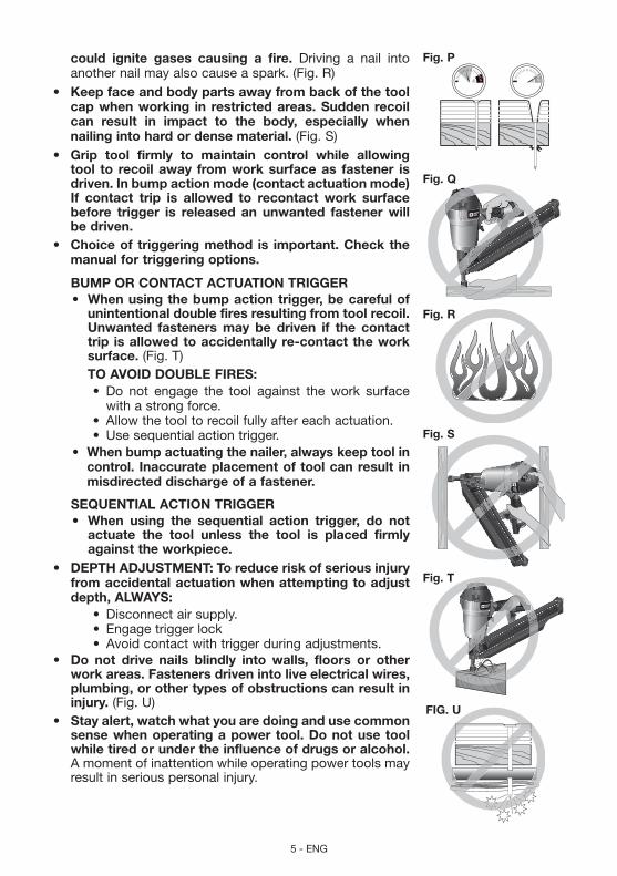
• Be aware that when the tool is being utilized atpressures on the high end of its operating range,nails can be driven completely through thin or verysoft work material. Make sure the pressure in thecompressor is set so that nails are set into thematerialandnotpushedcompletelythrough.(Fig. P)
• Keephandsandbodypartsclearof immediateworkarea.Holdworkpiecewithclampswhennecessarytokeephands andbodyoutofpotential harm.Be sure the workpiece is properly secured before pressing the nailer against the material.The contact trip may cause the work material to shift unexpectedly. (Fig. Q)
• Do not use tool in the presence of flammable dust,gases or fumes. The tool may produce a spark that
Fig.K
Fig.l
Fig.M
Fig.n
Fig.O
5 - ENG
could ignite gases causing a fire. Driving a nail into another nail may also cause a spark. (Fig. R)
• Keepfaceandbodypartsawayfrombackofthetoolcapwhenworking in restrictedareas.Suddenrecoilcan result in impact to the body, especially whennailingintohardordensematerial.(Fig. S)
• Grip tool firmly to maintain control while allowingtool to recoilaway fromworksurfaceas fastener isdriven.Inbumpactionmode(contactactuationmode)If contact trip is allowed to recontact work surfacebefore trigger is released an unwanted fastener willbedriven.
• Choiceof triggeringmethod is important.Checkthemanualfortriggeringoptions.
BUMpORCOnTACTACTUATIOnTRIGGeR• Whenusingthebumpactiontrigger,becarefulof
unintentionaldoublefiresresultingfromtoolrecoil.Unwanted fasteners may be driven if the contacttrip isallowedtoaccidentallyre-contacttheworksurface.(Fig. T)
TOAvOIDDOUBleFIReS:• Do not engage the tool against the work surface
with a strong force.• Allowthetooltorecoilfullyaftereachactuation.• Usesequentialactiontrigger.
• Whenbumpactuatingthenailer,alwayskeeptoolincontrol. Inaccurateplacementoftoolcanresult inmisdirecteddischargeofafastener.
SeqUenTIAlACTIOnTRIGGeR• When using the sequential action trigger, do not
actuate the tool unless the tool is placed firmlyagainsttheworkpiece.
• DepTHADJUSTMenT:Toreduceriskofseriousinjuryfromaccidentalactuationwhenattemptingtoadjustdepth,AlWAyS:
• Disconnectairsupply.• Engagetriggerlock• Avoidcontactwithtriggerduringadjustments.
• Do not drive nails blindly into walls, floors or otherworkareas.Fastenersdrivenintoliveelectricalwires,plumbing,orothertypesofobstructionscanresultininjury.(Fig. U)
• Stayalert,watchwhatyouaredoingandusecommonsensewhenoperatingapowertool.Donotusetoolwhiletiredorundertheinfluenceofdrugsoralcohol.A moment of inattention while operating power tools may result in serious personal injury.
Fig.q
Fig.R
Fig.S
Fig.p
Fig.T
FIG.U

6 - ENG
Use of this product may expose you to chemicals known to the State of California to cause cancer, birth defects and other reproductive harm. Avoidinhalingvaporsanddust,andwashhandsafterusing.
• Avoid prolonged contact with dust from power sanding, sawing,grinding, drilling, and other construction activities. Wear protectiveclothingandwashexposedareaswithsoapandwater. Allowing dust to get into your mouth, eyes, or lay on the skin may promote absorption of harmful chemicals.
Use of this tool can generate and/or disburse dust, which may cause serious and permanent respiratory or other injury. Always use NIOSH/OSHA approved respiratory protection appropriate for the dust exposure. Direct particles away from face and body. Always operate tool in well-ventilated area and provide for proper dust removal. Use dust collection system wherever possible.
ALWAYS USE SAFETY GLASSES. Everyday eyeglasses are NOT safety glasses. Also use face or dust mask if operation is dusty. ALWAYS WEAR CERTIFIED SAFETY EQUIPMENT:
• ANSIZ87.1eyeprotection(CAN/CSAZ94.3),• ANSIS12.6(S3.19)hearingprotection,• NIOSH/OSHArespiratoryprotection.
Before operating this tool, carefully read and understand all instructions inImportantSafetyInstructions.
save these instructionsnAIlSpeCIFICATIOnS
FR350Bnails 0.113"–0.148" (2.87–3.76 mm)
diameter, plastic collated round head framing nails lengths 2"–3-1/2"(50–90mm)
22º
AirInlet 1/4" NPT (6.4 mm)nOTe:UseonlypORTeR-CABleapprovedfasteners

7 - ENG
TOOlpARTSFig.1
A. Exhaust deflectorB. Selectable triggerC. Air Inlet with quick
connect couplerD. MagazineE. Nail stopF. Safety contact trip
with No-mar padG. Depth adjustment wheelH. Pusher releaseI. PusherJ. Trigger lock buttonk. Mode selector button
ASSeMBly
Disconnect air line from tool, engage trigger lock and removefasteners from magazine before making adjustments or personal injury mayresult.
TRIGGeR
Keep fingers AWAY from the trigger when not driving fasteners to avoid accidental actuation. Never carry a tool with finger on the trigger. In bump action mode (contact actuation mode), the tool will drive a fastener if the contact trip is bumped while the trigger is depressed.The FR350B is equipped with a selectable trigger. This trigger allows the operator to select either single sequential action trigger mode or bump action trigger mode. In accordance with the ANSI Standard SNT-101-2002, the trigger is assembled in the single sequential action trigger mode. To change the trigger mode, see ActuatingTool instructions in the Operation section of the manual. The selectable trigger also has a trigger lock button to keep the trigger locked at all times when the tool is not in use.
AIRFITTInGThe tool is equipped with a 1/4" (6.4 mm) male quick connector coupling. A 3/8" (9.5mm)malequickconnectorcouplingisavailablefromPORTER-CABLEandmaybeused when a 1/4" (6.4 mm) supply line is not available. nOTe: A 3/8" (9.5 mm) supply line (and fittings) are required for maximum toolperformance.
Always use couplings that relieve all pressure from the tool when it is disconnected from the power supply. Always use hose connectors that shut off air supply from compressor when the tool is disconnected.
A
F
K
G
J
CB
D
e
IH

8 - ENG
Toinstallanairfitting1. Wrap the male end of the fitting with thread seal tape prior to assembly to eliminate
air leaks.2. To install a 1/4" (6.4 mm) fitting: screw it directly into the air inlet and tighten firmly.
nOTe: If an adapter is in the air inlet, remove it prior to inserting the fitting. 3. Toinstalla3/8"(9.5mm)fitting:screwthefittingintothe3/8"(9.5mm)adapterand
then into the air inlet of the tool and tighten firmly.
OpeRATIOn
pRepARInGTHeTOOl
Read the section titledImportantSafetyInstructionsforpneumaticTools at the beginning of this manual. Always wear eye and ear protection when operating this tool. Keep the nailer pointed away from yourself and others. For safe operation, complete the following procedures and checks before each use of the nailer.
To reduce the risk of damage to the tool, only use PORTER-CABLE pneumatic tool oil or a non-detergent SAE 20 weight oil. Oil with additives or detergent will damage tool parts.
1. Before you use the nailer, be sure that the compressor tanks have been properly drained.
2. Lubricate tool: a. Use PORTER-CABLE pneumatic tool oil or a non-detergent S.A.E. 20 weight
oil. DO NOT use detergent oil or additives as they will damage O-rings and rubber parts.
b. Use a filter when possible. c. Add 5 to 7 drops of oil in the air fitting a least twice a day.3. Wear eye and ear protection.4. Ensure canister is empty of all fasteners.5. Check for smooth and proper operation of contact trip. Do not use tool if assembly
is not functioning properly. neveR tamper with the contact trip. neveR use a tool that has the contact trip restrained in the actuated position.
6. Check air supply: Ensure air pressure does not exceed recommended operating limits;70to120psi,(4.9to8.3bar,5to8.5kg/cm2).
7. Keep tool pointed away from yourself and others.8. Connect air hose.9. Checkforaudibleleaksaroundvalvesandgaskets.Neveruseatoolthatleaksor
has damaged parts.
To reduce the risk of personal injury, disconnect tool from airsupply and engage trigger lock before performing maintenance, clearing ajammedfastener,leavingworkarea,movingtooltoanotherlocationorhandingthetooltoanotherperson.
lOADInGTHeTOOl(FIG.1–4)
Keep the tool pointed away from yourself and others. Serious personal injury may result.
Never load nails with the contact trip or trigger activated. Personal injury may result.

9-ENG
1. Read all SafetyWarnings before using tool.2. Connect the air supply to the tool.3. Insert fasteners (L) into T-slot (K) on end cap of magazine (J) past the nail stop (E).
nOTe: Magazine will hold two full fastener strips.4. Pull pusher (I) back until the nail stop (E) falls behind the fasteners.
nOTe: Do not allow the pusher to snap forward against the nail strip, allowing this to happen could damage the nail collation.nOTe: This tool has a low nail lock out device which will not allow the tool to drive fasteners when the fastener quantity in the magazine is reduced to four. When unload-ing and loading the magazine always make sure these four nails have been removed from the magazine. If the nails are not removed from the magazine and the tool is reloaded and actuated, the nails will cause the tool to jam.
ACTUATInGTOOl
To reduce the risk of injury, AlWAyS wear proper eye ANSI Z87.1 (CAN/CSAZ94.3)andhearingprotectionANSIS12.6(S3.19)whenoperatingthistool.The tool can be actuated using one of two modes: single sequential actuation trigger mode and contact actuation trigger mode.
SingleSequentialactuationtrigger- (Fig.5)
Allow the tool to recoil off the work surface after actuation. If the contact trip remains depressed a nail will be driven each time the trigger is released and pulled, which could result in accidental actuation, possibly causing injury.
The sequential actuation trigger’s intended use is for intermittent fastening where accurate fastener placement is desired.
Tooperatethetool inSinglesequentialactuationmode:1. Depress the contact trip firmly against the work
surface.
Fig.5
S
Triggerlockbutton
Triggermodeselectorbutton
Fig.4 I
l
Fig.2
D JK
l
Fig.3
l
e
10 - ENG
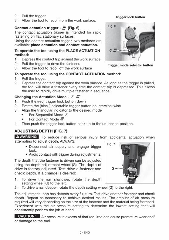
2. Pull the trigger.3. Allow the tool to recoil from the work surface.
Contactactuationtrigger- (Fig.6)The contact actuation trigger is intended for rapid fastening on flat, stationary surfaces.Using the contact actuation trigger, two methods are available: placeactuationandcontactactuation.
TooperatethetoolusingtheplACeACTUATIOnmethod:1. Depress the contact trip against the work surface.2. Pull the trigger to drive the fastener.3. Allow the tool to recoil off the work surface
TooperatethetoolusingtheCOnTACTACTUATIOnmethod:1. Pull the trigger.2. Depress the contact trip against the work surface. As long as the trigger is pulled,
the tool will drive a fastener every time the contact trip is depressed. This allows the user to rapidly drive multiple fastener in sequence.
ChangingtheActuationMode- 1. Push the (red) trigger lock button down2. Rotate the (black) selectable trigger button counterclockwise3. Align the triangular indicator to the desired mode
• ForSequentialMode• ForContactMode
4. Then push the trigger lock button back up to the un-locked position.
ADJUSTInGDepTH(FIG.7)
To reduce risk of serious injury from accidental actuation when attempting to adjust depth, ALWAYS:
• Disconnect air supply and engage triggerlock.
• Avoidcontactwithtriggerduringadjustments.
The depth that the fastener is driven can be adjusted using the depth adjustment wheel (G). The depth of drive is factory adjusted. Test drive a fastener and check depth. If a change is desired:
1. To drive the nail shallower, rotate the depth setting wheel (G) to the left.
2. To drive a nail deeper, rotate the depth setting wheel (G) to the right.
The adjustment knob has detents every full turn. Test drive another fastener and check depth. Repeat as necessary to achieve desired results. The amount of air pressure required will vary depending on the size of the fastener and the material being fastened. Experiment with the air pressure setting to determine the lowest setting that will consistently perform the job at hand.
Air pressure in excess of that required can cause premature wear and/or damage to the tool.
Fig.7
G
Fig.6
C
Triggerlockbutton
Triggermodeselectorbutton

11 - ENG
DIReCTIOnAlexHAUSTDeFleCTOR(FIG.8)Adjust directional exhaust deflector (A), so the exhaust air blast will be directed away from the operator. The exhaust deflector provides sixteen detented positions for directing the exhaust blast away from the operator. Grasp the deflector and rotate it to the desired position for the current application.
nO-MARpAD(FIG.9,10)
Disconnect tool from air supply and engage trigger lock, before removing or re-installing no-mar pad.The no-mar pad (F) is provided to reduce marring of the work surface. The no-mar pad can be removed, and stored inside the End Cap, Magazine (M), to provide increased depth-of-drive for toe-nailing applications.
CleARInGAJAMMeDnAIl(FIG.1,11–13)
Disconnect air line from tool, engage trigger lock and removefasteners from magazine before making adjustments or personal injury mayresult.If a nail becomes jammed in the nosepiece, keep the tool pointed away from you and follow these instructions to clear:1. Disconnect the air supply from the tool and engage trigger lock.2. Depress pusher release (H) and slide pusher (I) all the way to the front of the
magazine.3. Depress nail stop (E) and slide fasteners from magazine.
4. If nail is jammed between the driver and nose casting force driver blade back to the top using a 1/4" (6.4 mm) punch and hammer. When the nail is released it will fall free or can be removed using pliers.
Fig.8
A
Fig.9
F
Fig.10
M
Fig.11HI e

12 - ENG
5. If nail still can not be removed, remove the magazine:
a. Remove screws (N). b. Remove magazine. c. Remove bent nail. d. Reassemble in reverse order. nOTe: Should nails continue to jam frequently in nosepiece, have tool serviced by an authorized PORTER-CABLE service center.
COlDWeATHeROpeRATIOnWhen operating tools at temperatures below freezing:1. Make sure compressor tanks have been properly drained prior to use.2. Keep tool as warm as possible prior to use.3. Make certain all fasteners have been removed from magazine.4. Put 5 to 7 drops of PORTER-CABLE pneumatic tool oil in the air inlet.5. Lower air pressure to 80 psi (5.5 bar) or less.6. Reconnect air and load nails into magazine. 7. Actuate the tool 5 or 6 times into scrap lumber to lubricate O-rings.8. Turn pressure up to operating level (not to exceed 120 psi) and use tool as normal. 9. Re-lubricateatleastoncedaily.10. Always drain the compressor tanks at least once a day.
HOTWeATHeROpeRATIOnTool should operate normally. However, keep tool out of direct sunlight as excessive heat can deteriorate bumpers, O-rings and other rubber parts resulting in increased maintenance.
Fig.12 Fig.13
n
n

13 - ENG
MAInTenAnCe
Disconnect air line from tool, engage trigger lock and removefasteners from magazine before making adjustments or personal injury mayresult.
DAIlyMAInTenAnCeCHART
ACTIOn WHy HOWLubricate tool with 5-7 drops of PORTER-CABLE Pneumatic Tool Oil
Prevents failure of o-rings
Insert drops into air fitting on end cap of tool
Drain compressor tanks and hoses daily
Prevents accumulation of moisture in compressor and nailer
Open petcocks or other drain valves on compressor tanks. Allow any accumulated water to drain from hoses
Clean magazine, magazine release and contact trip mechanism.
Permits smooth operation of magazine, reduces wear and prevents jams.
Blow clean with compressor air. The use of oils, lubricants periodically or solvents is not recommended as they tend to attract debris.
Before each use, check to insure all screws, nuts and fasteners are tight and undamaged.
Prevents jams, leaks and premature failure of tool parts.
Tighten loose screws or other fasteners using the appropriate hex wrench or screwdriver.
CleAnInG
Never use solvents or other harsh chemicals for cleaning the non-metallic parts of the tool. These chemicals may weaken the materials used in these parts. Use a cloth dampened only with water and mild soap. Never let any liquid get inside the tool; never immerse any part of the tool into a liquid.
RepAIRSFor assistance with your tool, visit our website at www.portercable.com for a list of service centers, or call the PORTER-CABLE Customer Care Center at 1-888-848-5175 (U.S. & Canada Only).
SeRvICeReplACeMenTpARTSUse only identical replacement parts. For a parts list or to order parts, visit our service website at http://servicenet.deltaportercable.com/. You can also order parts from your nearest PORTER-CABLE Factory Service Center or PORTER-CABLE Authorized Warranty Service Center. Or, you can call our Customer Care Center at 1-888-848-5175 (U.S. & Canada Only).
SeRvICeAnDRepAIRSAll quality tools will eventually require servicing and/or replacement of parts. For information about PORTER-CABLE, its factory service centers or authorized warranty service centers, visit our website at www.portercable.com or call our Customer Care Center at 1-888-848-5175 (U.S. & Canada Only). All repairs made by our service centers

14 - ENG
are fully guaranteed against defective material and workmanship. We cannot guarantee repairs made or attempted by others.You can also write to us for information at PORTER-CABLE, 4825 Highway 45 North, Jackson, Tennessee 38305 - Attention: Product Service. Be sure to include all of the information shown on the nameplate of your tool (model number, type, serial number, etc.).
ACCeSSORIeS
Since accessories, other than those offered by PORTER-CABLE, have not been tested with this product, use of such accessories with this tool could be hazardous. To reduce the risk of injury, only PORTER-CABLE recommended accessories should be used with this product.
A complete line of accessories is available from your PORTER-CABLE Factory Service Center or a PORTER-CABLE Authorized Warranty Service Center. Please visit our Web Site www.portercable.com for a catalog or for the name of your nearest supplier.
THReeyeARlIMITeDWARRAnTypORTeR-CABle will repair, without charge, any defects due to faulty materials or workmanship for three years from the date of purchase. This warranty does not cover part failure due to normal wear or tool abuse. For further detail of warranty coverage and warranty repair information, visit www.portercable.com or call 1-888-848-5175 (U.S. & Canada Only). This warranty does not apply to accessories or damage caused where repairs have been made or attempted by others. This warranty gives you specific legal rights and you may have other rights which vary in certain states or provinces.In addition to the warranty, PORTER-CABLE tools are covered by our:1yeARFReeSeRvICe:PORTER-CABLE will maintain the tool and replace worn parts caused by normal use, for free, any time during the first year after purchase.90 DAy MOney BACK GUARAnTee: If you are not completely satisfied with the performance of your PORTER-CABLE Power Tool, Laser, or Nailer for any reason, you canreturnitwithin90daysfromthedateofpurchasewithareceiptforafullrefund–noquestions asked.lATInAMeRICA:This warranty does not apply to products sold in Latin America. For products sold in Latin America, see country specific warranty information contained in the packaging, call the local company or see website for warranty information.To register your tool for warranty service visit our website at www.portercable.com.
WARnInGlABelReplACeMenTIf your warning labels become illegible or are missing, call 1-888-848-5175 (U.S. & Canada Only) for a free replacement.
15 - ENG
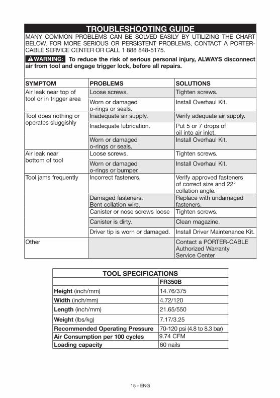
TROUBleSHOOTInGGUIDeMANY COMMON PROBLEMS CAN BE SOLVED EASILY BY UTILIZING THE CHART BELOW. FOR MORE SERIOUS OR PERSISTENT PROBLEMS, CONTACT A PORTER-CABLE SERVICE CENTER OR CALL 1 888 848-5175.
Toreducetheriskofseriouspersonalinjury,AlWAySdisconnectairfromtoolandengagetriggerlock,beforeallrepairs.
SyMpTOM pROBleMS SOlUTIOnSAir leak near top of tool or in trigger area
Loose screws. Tighten screws.
Worn or damaged o-rings or seals.
Install Overhaul Kit.
Tool does nothing or operates sluggishly
Inadequate air supply. Verify adequate air supply.
Inadequate lubrication. Put 5 or 7 drops of oil into air inlet.
Worn or damaged o-rings or seals.
Install Overhaul Kit.
Air leak near bottom of tool
Loose screws. Tighten screws.
Worn or damaged o-rings or bumper.
Install Overhaul Kit.
Tool jams frequently Incorrect fasteners. Verify approved fasteners of correct size and 22° collation angle.
Damaged fasteners. Bent collation wire.
Replace with undamaged fasteners.
Canister or nose screws loose Tighten screws.
Canister is dirty. Clean magazine.
Driver tip is worn or damaged. Install Driver Maintenance Kit.
Other Contact a PORTER-CABLE Authorized Warranty Service Center
TOOlSpeCIFICATIOnSFR350B
Height (inch/mm) 14.76/375
Width (inch/mm) 4.72/120
length (inch/mm) 21.65/550
Weight (lbs/kg) 7.17/3.25
RecommendedOperatingpressure 70-120 psi (4.8 to 8.3 bar)AirConsumptionper100cycles 9.74CFMloadingcapacity 60 nails
16 - ENG
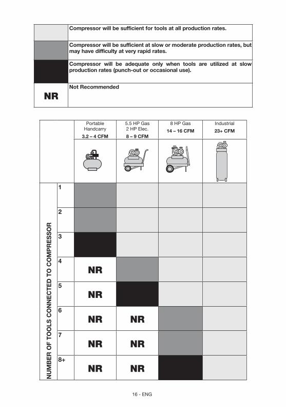
Compressorwillbesufficientfortoolsatallproductionrates.
Compressorwillbesufficientatslowormoderateproductionrates,butmayhavedifficultyatveryrapidrates.
Compressor will be adequate only when tools are utilized at slowproductionrates(punch-outoroccasionaluse).
NRnotRecommended
Portable Handcarry
3.2–4CFM
5.5 HP Gas 2 HP Elec.
8–9CFM
8 HP Gas
14–16CFM
Industrial
23+CFM
nU
MB
eR
OF
TO
OlS
CO
nn
eC
Te
DT
OC
OM
pR
eS
SO
R
1
2
3
4
NR
5
NR
6
NR NR
7
NR NR
8+
NR NR