roundabouts: an informational guide · pdf file8.4.4 geometric design parameters 223 8.5...
TRANSCRIPT

System Considerations88.1 Traffic Signals at Roundabouts 213
8.1.1 Metered entrance 214
8.1.2 Nearby vehicular and pedestrian signals 214
8.1.3 Full signalization of the circulatory roadway 215
8.2 At-Grade Rail Crossings 215
8.3 Closely Spaced Roundabouts 217
8.4 Roundabout Interchanges 219
8.4.1 Two-bridge roundabout interchange 219
8.4.2 One-bridge roundabout interchange 220
8.4.3 Analysis of roundabout interchanges 222
8.4.4 Geometric design parameters 223
8.5 Roundabouts in an Arterial Network 223
8.5.1 Platooned arrivals on roundabout approaches 224
8.5.2 Roundabout departure pattern 224
8.5.3 Wide nodes and narrow roads 225
8.6 Microscopic Simulation 227
8.6.1 How to use simulation 227
8.6.2 Examples of simulation models 228
8.7 References 229

Federal Highway Administration212
Exhibit 8-1. Rail crossing treatments at roundabouts. 216
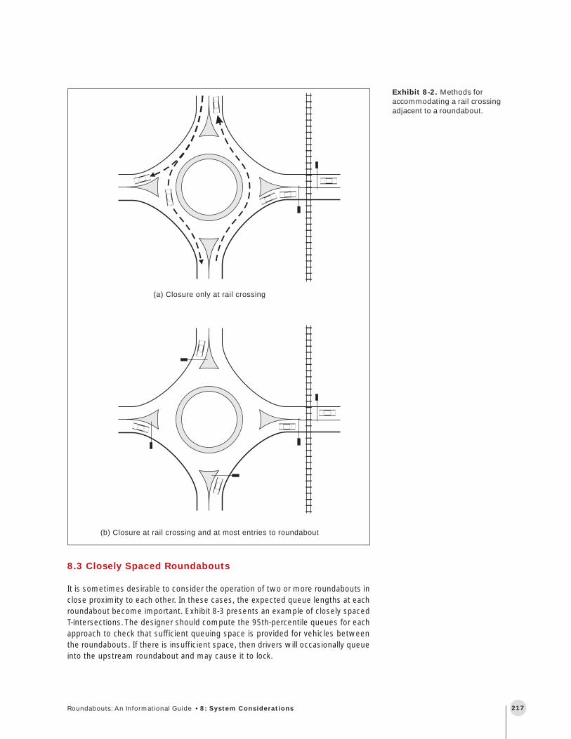
Exhibit 8-2. Methods for accommodating a rail crossing
adjacent to a roundabout. 217
Exhibit 8-3. Example of closely spaced offset T-intersections
with roundabouts. 218
Exhibit 8-4. Through bypass lanes at staggered T-intersections. 218
Exhibit 8-5. Two-bridge roundabout interchange. 219
Exhibit 8-6. Examples of two-bridge roundabout interchanges. 220
Exhibit 8-7. Examples of one-bridge roundabout interchanges
with circular central islands. 221
Exhibit 8-8. One-bridge roundabout interchange with
raindrop-shaped central islands. 222
Exhibit 8-9. Roundabouts in an arterial network. 223
Exhibit 8-10. Wide nodes and narrow roads. 226
Exhibit 8-11. Summary of simulation models for roundabout
analysis. 228

213Roundabouts: An Informational Guide • 8: System Considerations
Roundabouts have been considered as isolated intersections in most other inter-national roundabout guides and publications. However, roundabouts may need tofit into a network of intersections, with the traffic control functions of a roundaboutsupporting the function of nearby intersections and vice versa. The purpose of thischapter is to provide some guidance on potentially difficult, but not uncommon,circumstances or constraints.
Many countries whose initial design and driver experience was with isolated round-abouts have since extended their application to transportation system design andoperation. This chapter addresses the appropriate use of roundabouts in a roadwaynetwork context and the benefits obtained. Since the design of each roundaboutshould generally follow the principles of isolated roundabout design, the discus-sion is at a conceptual and operational level and generally complements the plan-ning of isolated roundabouts discussed in Chapter 3. In many cases, site-specificissues will determine the appropriate roundabout design elements.
To establish some fundamental understanding for subsequent discussion, threedesign issues at an isolated roundabout are presented. First, this chapter will de-scribe the requirements and effects of signal control of one or more legs of aroundabout, as well as the entire roundabout. It is noted that fully signalized round-abouts are not desirable. Next, modified designs that incorporate at-grade rail cross-ings are discussed. It is noted that intersections with rail lines passing throughthem or near them are not desirable. However, these situations do occur and wouldthen need to be analyzed.
Building upon this understanding, the next sections address design and perfor-mance of two closely spaced roundabouts and the specific application to round-about interchanges. This is followed by issues pertaining to the use of roundaboutson an arterial or network that may include or replace coordinated signalized inter-sections. Finally, the role of microscopic simulation models in assisting with analy-sis of these system effects is reviewed.
8.1 Traffic Signals at Roundabouts
Although yield control of entries is the default at roundabouts, when necessary,traffic circles and roundabouts have been signalized by metering one or more en-tries, or signalizing the circulatory roadway at each entry. Roundabouts should neverbe planned for metering or signalization. However, unexpected demand may dic-tate the need after installation. Each of these will be discussed in turn. In the firstcase, entrance metering can be implemented at the entrance or some distanceupstream.
This chapter considers
roundabouts as they relate to
other elements of the
transportation system,
including other intersections.
Chapter 8 System Considerations

Federal Highway Administration214
8.1.1 Metered entrance
Roundabouts operate effectively only when there are sufficient longer and accept-able gaps between vehicles in the circulatory lanes. If there is a heavy movementof circulating drivers, then entering drivers at the next downstream entry may notbe able to enter. This situation occurs most commonly during the peak periods, andthe performance of the roundabout can be greatly improved with entrance metering.
The concept of entrance metering at roundabouts is similar to ramp metering onfreeways. A convenient sign is a changeable one that reads “Stop on red signal”and shows the usual yield sign for a roundabout otherwise. The sign would alsoinclude a yellow and red signal above the sign. The operation of the sign would beto show drivers the roundabout sign, display the yellow light and the sign “Stop onred signal,” and finally display the red light and the same text sign. This wouldcause entering vehicles to stop and allow the vehicles at the downstream entranceto proceed. A queue length detector on the downstream entrance may be used toindicate to the signal controller when the metering should be activated and deacti-vated. Once on the circulatory roadway, vehicles are not stopped from leaving theroundabout.
8.1.2 Nearby vehicular and pedestrian signals
Another method of metering is the use, with appropriate timing, of a nearby up-stream signalized intersection or a signalized pedestrian crossing on the subjectapproach road. Unlike pure entry metering, such controls may stop vehicles fromentering and leaving the roundabout, so expected queue lengths on the round-about exits between the metering signal and the circulatory roadway should becompared with the proposed queuing space.
Because of additional objectives and constraints, metering by upstream signals isgenerally not as effective as direct entrance metering. However, a signalized pe-destrian crossing may be desirable on its own merits. More than one entrance canbe metered, and the analyst needs to identify operational states and evaluate eachone separately to provide a weighted aggregate performance measure.
When disabled pedestrians and/or school children are present at a high-volumesite, a pedestrian-actuated traffic signal could be placed 20 to 50 m (65 to 165 ft)from the yield line. This longer distance than at an unsignalized crossing may berequired because the vehicle queues downstream of the roundabout exit will belonger. The trade-offs for any increased distance requirement are increased walk-ing distances and higher exiting vehicle speeds. An analysis of signal timing will beneeded to minimize queuing of vehicles into the roundabouts.
Roundabouts should not be
planned for metering or
signalization unless
unexpected demand dictates
this need after installation.
Nearby intersections or
pedestrian crossing signals can
also meter traffic, but not as
effectively as direct
entrance metering.

215Roundabouts: An Informational Guide • 8: System Considerations
Full signalization of the
circulatory roadway requires
careful coordination and
vehicle progression.
8.1.3 Full signalization of the circulatory roadway
Full signalization that includes control of circulating traffic at junctions with majorentrances is possible at large-diameter multilane traffic circles or rotaries that haveadequate storage space on the circulatory roadway. The double-lane roundaboutdimensions resulting from the design criteria recommended in this guide may pre-clude such possibilities. As stated previously, full signalization should in any caseonly be considered as a retrofit alternative resulting from unanticipated traffic de-mands. Other feasible alternatives should also be considered, such as flaring criti-cal approaches, along with the associated widening of the circulatory roadway;converting a large-diameter rotary to a more compact modern roundabout form; orconverting to a conventional signalized intersection. This guide recommends thatsignalizing roundabouts to improve capacity be considered only when it is the mostcost-effective solution.
Traffic signals at fully signalized rotaries should be timed carefully to prevent queu-ing on the circulatory roadway by ensuring adequate traffic progression of circulat-ing traffic and especially critical movements. Introducing continuous or part-timesignals on the circulatory roadway requires careful design of geometry, signs, lanemarkings, and signal timing settings, and literature on this specific topic should beconsulted (1, 2).
8.2 At-Grade Rail Crossings
Locating any intersection near an at-grade railroad crossing is generally discour-aged. However, roundabouts are sometimes used near railroad-highway at-gradecrossings. Rail transit, including stations, have successfully been incorporated intothe medians of approach roadways to a roundabout, with the tracks passing throughthe central island. In such situations, the roundabout either operates partially dur-ing train passage, or is completely closed to allow the guided vehicles or trains topass through. The treatment of at-grade rail crossings should follow primarily therecommendations of the Manual on Uniform Traffic Control Devices (MUTCD) (3).Another relevant reference is the FHWA Railroad-Highway Grade Crossing Hand-book (4).
There are essentially two ways in which rails can interact with a roundabout, asshown in Exhibit 8-1:
• Through the center; or
• Across one leg in close proximity to the roundabout.

Federal Highway Administration216
In either case, traffic must not be forced to stop on the tracks. A new intersectionshould not be designed with railroad tracks passing through the center of it. How-ever, on occasions, the rail line passes through an existing intersection area. Thetraffic engineer might be faced with a decision whether to change the intersectiontype to a roundabout or to grade-separate the crossing.
A gated rail crossing through the center of a roundabout can be accommodated intwo ways. The first method is to prevent all vehicular traffic from entering the round-about. The second method is to prevent traffic from crossing the tracks while stillallowing some movements to occur. This latter method will have lower delays andqueues, but it may be more confusing and less safe.
A gated rail crossing adjacent to a roundabout can be accommodated in two ways,as shown in Exhibit 8-2:
• Method A: Closure only at rail crossing. This method prohibits vehicles fromcrossing the rails but still allows vehicles to enter and leave the circulatory road-way. This method allows for many of the movements through the roundabout tocontinue to run free, if a queue does not build to the point of impeding circula-tion within the roundabout. A queuing analysis should be performed using theexpected volume crossing the rails and the expected duration of rail crossing todetermine the likelihood that this blockage will occur. In general, this methodworks better than Method B if there is sufficient separation between the round-about and the rail crossing. If blockage is anticipated, the designer should chooseMethod B.
• Method B: Closure at rail crossing and at most entries to the roundabout. Thismethod closes all entries to the roundabout except for the entry nearest the railcrossing. This allows any vehicles in the roundabout to clear prior to the arrivalof the train. In addition, a gate needs to be provided on the approach to the railcrossing exiting the roundabout to protect against possible U-turns in the round-about. This causes increased queuing on all approaches but is generally saferthan Method A when there is insufficient storage capacity between the round-about and rail crossing.
Closing only the leg with the
rail crossing may work if
queues are not anticipated to
back into the
circulatory roadway.
Exhibit 8-1. Rail crossingtreatments at roundabouts.
217Roundabouts: An Informational Guide • 8: System Considerations
(b) Closure at rail crossing and at most entries to roundabout
(a) Closure only at rail crossing
8.3 Closely Spaced Roundabouts
It is sometimes desirable to consider the operation of two or more roundabouts inclose proximity to each other. In these cases, the expected queue lengths at eachroundabout become important. Exhibit 8-3 presents an example of closely spacedT-intersections. The designer should compute the 95th-percentile queues for eachapproach to check that sufficient queuing space is provided for vehicles betweenthe roundabouts. If there is insufficient space, then drivers will occasionally queueinto the upstream roundabout and may cause it to lock.
Exhibit 8-2. Methods foraccommodating a rail crossingadjacent to a roundabout.

Federal Highway Administration218
France (5)
Closely spaced roundabouts may improve safety by “calming” the traffic on themajor road. Drivers may be reluctant to accelerate to the expected speed on thearterial if they are also required to slow again for the next close roundabout. Thismay benefit nearby residents.
When roundabouts are used at offset T-intersections, there is an opportunity tobypass one through lane direction on the major road at each roundabout. Exhibit8-4 presents sketches of through bypass lanes for the two basic types of offsetT-intersection configurations. In both cases, through traffic in each direction needsto negotiate only one roundabout, and capacity is therefore typically improved. Theweaving section should be analyzed both for capacity and for safety through anevaluation of the relative speeds of the weaving vehicles.
Exhibit 8-4. Throughbypass lanes at staggered
T-intersections.
Exhibit 8-3. Example ofclosely spaced offset
T-intersection withroundabouts.
Closely spaced roundabouts
may have a traffic calming
effect on the major road.
Option A (roundabout precedes
bypass) is preferred.

219Roundabouts: An Informational Guide • 8: System Considerations
Of the two arrangements shown in Exhibit 8-4, Option A (roundabout precedesbypass) is preferred. The roundabout offers a visual cue to drivers to slow in Ar-rangement A and encourages slower (and therefore safer) driving through the tworoundabouts. If Option B (bypass precedes roundabout) is used, the merges anddiverges could occur at higher speeds. It may be appropriate in this case to omitthe bypass lane and pass all through traffic through both roundabouts. Anotheradvantage of Option A is that there would be less queuing of traffic on the roadspace between the roundabouts.
Note that when conventional T-intersections are used, Option A is less preferablethan Option B due to the need to provide interior storage space for left turns inOption A. Therefore, roundabouts may be a satisfactory solution for cases likeOption A.
8.4 Roundabout Interchanges
Freeway ramp junctions with arterial roads are potential candidates for roundaboutintersection treatment. This is especially so if the subject interchange typically hasa high proportion of left-turn flows from the off-ramps and to the on-ramps duringcertain peak periods, combined with limited queue storage space on the bridgecrossing, off-ramps, or arterial approaches. In such circumstances, roundaboutsoperating within their capacity are particularly amenable to solving these problemswhen compared with other forms of intersection control.
8.4.1 Two-bridge roundabout interchange
There are two basic types of roundabout interchanges. The first is a large diameterroundabout centered over or under a freeway. The ramps connect directly into theroundabout, as do the legs from the crossroad. This is shown in Exhibit 8-5.
Exhibit 8-5. Two-bridgeroundabout interchange.
Source: Based on (6)
The freeway may go either
over or under the circulatory
roadway.

Federal Highway Administration220
This type of interchange requires two bridges. If the roundabout is above the free-way as shown in Exhibit 8-5, then the bridges may be curved. Alternatively, if thefreeway goes over the roundabout then up to four bridges may be required. Thenumber of bridges will depend on the optimum span of the type of structure com-pared with the inscribed diameter of the roundabout island and on whether theone bridge is used for both freeway directions or whether there is one bridge foreach direction. The road cross-section will also influence the design decision. Ex-hibit 8-6 shows an example from the United Kingdom. The designer should decideif the expected speeds of vehicles at larger roundabouts are acceptable.
Exhibit 8-6. Examples of two-bridge roundabout
interchanges.
A50/Heron Cross, United Kingdom (mirrored to show right-hand-side driving)
8.4.2 One-bridge roundabout interchange
The second basic type uses a roundabout at each side of the freeway and is aspecific application of closely spaced roundabouts discussed in the previous sec-tion. A bridge is used for the crossroad over the freeway or for a freeway to crossover the minor road. Again, two bridges may be used when the freeway crossesover the minor road.
This interchange form has been used successfully in some cases to defer the needto widen bridges. Unlike signalized ramps that may require exclusive left-turn lanesacross the bridge and extra queue storage, this type of roundabout interchangeexhibits very little queuing between the intersections since these movements arealmost unopposed. Therefore, the approach lanes across the bridge can be mini-mized.
The actual roundabouts can have two different shapes or configurations. The firstconfiguration is a conventional one with circular central islands. This type of con-figuration is recommended when it is desirable to allow U-turns at each round-about or to provide access to legs other than the cross street and ramps. Examplesfrom the United Kingdom and France are shown in Exhibit 8-7.
One-bridge roundabout
interchanges have been
successfully used to defer the
need for bridge widening.

221Roundabouts: An Informational Guide • 8: System Considerations
Exhibit 8-7 (continued).Examples of one-bridgeroundabout interchanges withcircular central islands.
France
Exhibit 8-7. Examples ofone-bridge roundaboutinterchanges with circularcentral islands.
United Kingdom

Federal Highway Administration222
8.4.3 Analysis of roundabout interchanges
The traffic performance evaluation of the roundabout interchange is the same asfor a single conventional roundabout. The maximum entry capacity is dependenton the circulatory flow and the geometry of the roundabouts. The evaluation pro-cess is included in Chapter 4.
The benefits and costs associated with this type of interchange also follow thosefor a single roundabout. A potential benefit of roundabout interchanges is that thequeue length on the off-ramps may be less than at a signalized intersection. Inalmost all cases, if the roundabout would operate below capacity, the performanceof the on-ramp is likely to be better than if the interchange is signalized. The head-way between vehicles leaving the roundabout along the on-ramp is more randomthan when signalized intersections are used. This more random ramp traffic allowsfor smoother merging behavior on the freeway and a slightly higher performanceat the freeway merge area compared with platooned ramp traffic from a signalizedintersection.
The second configuration uses raindrop-shaped central islands that preclude someturns at the roundabout. This configuration is best used when ramps (and not front-age roads) intersect at the roundabout. A raindrop central island can be consideredto be a circular shape blocked at one end. In this configuration, a driver wanting tomake a U-turn has to drive around both raindrop-shaped central islands. This con-figuration has an additional advantage in that it makes wrong-way turns into theoff-ramps more difficult. On the other hand, drivers do not have to yield whenapproaching from the connecting roadway between the two roundabouts. If theroundabout is designed poorly, drivers may be traveling faster than they should tonegotiate the next roundabout safely. The designer should analyze relative speedsto evaluate this alternative. On balance, if the length of the connecting road isshort, this design may offer safety advantages. Exhibit 8-8 provides an example ofthis type of interchange configuration.
Interstate 70/Avon Road, Avon, CO
Raindrop central islands make
wrong-way movements more
difficult, but require navigating
two roundabouts to
make a U-turn.
Roundabouts produce more
random headways on ramps
than signalized intersections,
resulting in smoother merging
behavior on the freeway.
Exhibit 8-8. One-bridgeroundabout interchange with
raindrop-shaped central islands.

223Roundabouts: An Informational Guide • 8: System Considerations
The traffic at any entry is the same for both configurations. The entry capacity isthe same and the circulating flow is the same for the large single roundabout (Ex-hibit 8-6) and for the second configuration of the two teardrop roundabout system(Exhibit 8-8). Note that the raindrop form may be considered and analyzed as asingle large roundabout as in the circular roundabout interchange, but with a“pinched” waistline across or under one bridge rather than two. The relative perfor-mance of these systems will only be affected by the geometry of the roundaboutsand islands. The system with the two circular roundabouts will have a slightly differ-ent performance depending upon the number of U-turns.
8.4.4 Geometric design parameters
The design parameters are not restrained by any requirement here. They are onlyconstrained by the physical space available to the designer and the configurationselected. The raindrop form can be useful if grades are a design issue since theyremove a potential cross-slope constraint on the missing circulatory road segments.
If there are more roads intersecting with the interchange than the single crossroad, then two independent circular roundabouts are likely to be the best solution.
8.5 Roundabouts in an Arterial Network
In order to understand how roundabouts operate within a roadway system, it isimportant to understand their fundamental arrival and departure characteristicsand how they may interact with other intersections. Exhibit 8-9 gives an exampleof a series of roundabouts along an arterial street.
Exhibit 8-9. Roundabouts inan arterial network.
Avon Road, Avon, CO
The Avon Road network
consists of five roundabouts
(all pictured)—two at the
interchange ramp terminals
and three along the arterial
south of the freeway.
Federal Highway Administration224
8.5.1 Platooned arrivals on roundabout approaches
The performance of a roundabout is affected by its proximity to signalized intersec-tions. If a signalized intersection is very close to the roundabout, it causes vehiclesto enter the roundabout in closely spaced platoons; more importantly, it results inregular periods when no vehicles enter. These latter periods provide an excellentopportunity for traffic on the next downstream entry to enter. Since the critical gapis larger than the follow-up time, a roundabout becomes more efficient when thevehicles are handled as packets of vehicles rather than as isolated vehicles.
When the signalized intersection is some distance from the roundabout, then thevehicles’ arrival patterns have fewer closely spaced platoons. Platoons tend to dis-perse as they move down the road. The performance of a roundabout will be re-duced under these circumstances when compared with a close upstream signal. Ifarrival speeds are moderate, then few longer gaps allow more drivers to enter aroundabout than a larger number of shorter gaps. If arrival speeds are low, thenthere are more opportunities for priority-sharing (where entering and circulatingvehicles alternate) and priority-reversals (where the circulating vehicles tend toyield to entering vehicles) between entering and circulating traffic streams, and theinfluence of platoon dispersal is not as marked.
8.5.2 Roundabout departure pattern
Traffic leaving a roundabout tends to be more random than if another type of inter-section control were used. A roundabout may therefore affect the performance of
Signalized intersections close
to roundabouts produce gaps
in traffic that can be used by
minor street traffic to enter the
major street.
Even one circulating vehicle in
a roundabout will result in a
platoon breaking down.
other unsignalized intersections or driveways more than if the intersection wassignalized. However, as this traffic travels further along the road downstream ofthe roundabout, the faster vehicles catch up to the slower vehicles and the propor-tion of platooning increases.
In the case of a well-defined platoon from an upstream signalized intersectionarriving at a downstream unsignalized intersection just after a well-defined platoonarrives from the other direction, it may be difficult for the minor street drivers atthis unsignalized intersection to enter the link. If, on the other hand, one of thesesignalized intersections were to be replaced by a roundabout, then the effect of therandom traffic from the roundabout might be relatively advantageous. Under theseconditions, more dispersed platoons (or random) traffic could assist drivers enter-ing along the link at the unsignalized intersection.
If a roundabout is used in a network of coordinated signalized intersections, then itmay be difficult to maintain the closely packed platoons required. If a tightly packedplatoon approached a roundabout, it could proceed through the roundabout as longas there was no circulating traffic or traffic upstream from the left. Only one circu-lating vehicle would result in the platoon breaking down. Hence, the use of round-abouts in a coordinated signalized network needs to be evaluated carefully. Onepossibility for operating roundabouts within a signal network is to signalize themajor approaches of the roundabout and coordinate them with adjacent upstreamand downstream signalized intersections.

225Roundabouts: An Informational Guide • 8: System Considerations
Another circumstance in which a roundabout may be advantageous is as an alter-native to signal control at a critical signalized intersection within a coordinated net-work. Such intersections are the bottlenecks and usually determine the requiredcycle length, or are placed at a signal system boundary to operate in isolated actu-ated mode to minimize their effect on the rest of the surrounding system. If aroundabout can be designed to operate within its capacity, it may allow a loweringof the system cycle length with resultant benefits to delays and queues at otherintersections.
Because roundabouts accommodate U-turns more easily than do signals, they mayalso be useful as an access management tool. Left-turn exits from driveways ontoan arterial which may currently experience long delays and require two-stage left-turn movements could be replaced with a simpler right turn, followed by a U-turn atthe next roundabout.
8.5.3 Wide nodes and narrow roads
The ultimate manifestation of roundabouts in a system context is to use them inlieu of signalized intersections. Some European cities such as Nantes, France, andsome Australian cities have implemented such a policy. It is generally recognizedthat intersections (or nodes), not road segments (or links), are typically the bottle-necks in urban roadway networks. A focus on maximizing intersection capacityrather than widening streets may therefore be appropriate. Efficient, signalizedintersections, however, usually require that exclusive turn lanes be provided, withsufficient storage to avoid queue spillback into through lanes and adjacent inter-sections. In contrast, roundabouts may require more right-of-way at the nodes, butthis may be offset by not requiring as many basic lanes on the approaches, relativeto signalized arterials. This concept is demonstrated in Exhibit 8-10.
Analysis tools, such as those provided in Chapter 4, should be used to evaluate thearterial or network. These may be supplemented by appropriate use of microscopicsimulation models as discussed next. Supplemental techniques to increase thecapacity of critical approaches may be considered if necessary, such as bypasslanes, flaring of approaches and tapering of exits, and signalization of some round-about approaches.
Roundabouts as an access
management tool.
Roundabouts may require
more right-of-way at
intersections, but may also
allow fewer lanes (and less
right-of-way) between
intersections.

Federal Highway Administration226
Exhibit 8-10. Wide nodes andnarrow roads.

227Roundabouts: An Informational Guide • 8: System Considerations
8.6 Microscopic Simulation
Microscopic simulation of traffic has become a valuable aid in assessing the systemperformance of traffic flows on networks, as recognized by the Highway CapacityManual 2000 (7). Analysis of many of the treatments discussed in this chapter maybenefit from the use of appropriate simulation models used in conjunction with ana-lytic models of isolated roundabouts discussed in Chapter 4. These effects includemore realistic modeling of arrival and departure profiles, time-varying traffic patterns,measurement of delay, spatial extent and interaction of queues, fuel consumption,emissions, and noise. However, the user must carefully select the appropriate mod-els and calibrate the model for a particular use, either against field data, or othervalidated analytic models. It would also be advisable to check with others to see ifthere have been any problems associated with the use of the model.
8.6.1 How to use simulation
Microscopic simulation models are numerous and new ones are being developed,while existing models are upgraded frequently. Each model may have particularstrengths and weaknesses. Therefore, when selecting a model, analysts should con-sider the following:
• Should a simulation model be used, or is an isolated analytic roundabout modelsufficient?
• What are the model input requirements, are they sufficient, and how can they beprovided or estimated?
• What outputs does the model provide in animated, graphical, or tabular form?
• What special features of the model are pertinent to the problem being addressed?
• Does the user manual for the simulation model specifically address modeling aroundabout?
• How sensitive is the model to various geometric parameters?
• Is there literature on the validation of this model for evaluating roundabouts?
• Is there sufficient information available on the microscopic processes being usedby the model such as car following, gap acceptance, lane changing, or steering?(The availability of animation can assist in exposing model logic.)
• Are relevant past project examples available?
When a simulation model is used, the analyst is advised to use the results to makerelative comparisons of the differences between results from changing conditions,and not to conclude that the absolute values found from the model are equivalent tofield results. It is also advisable to perform a sensitivity analysis by changing selectedparameters over a range and comparing the results. If a particular parameter is found

Federal Highway Administration228
to affect the outcomes significantly, then more attention should be paid to accu-rate representation and calibration of this parameter. Finally, the analyst shouldcheck differences in results from using different random number seeds. If the dif-ferences are large, then the simulation time should be increased substantially.
8.6.2 Examples of simulation models
Five commercially available microscopic simulation models are CORSIM, Integra-tion, Simtraffic, Paramics, and VISSIM. The first three are North American models;Paramics is from Scotland, and VISSIM is from Germany. The following sectionspresent a brief overview of each model. Since software packages (and simulationmodels in particular) are in constant development, the user is encouraged to con-sult the most current information available on each model.
Simulation results are best
used for relative comparisons,
rather than relying on absolute
values produced by the model.
Exhibit 8-11. Summary ofsimulation models forroundabout analysis.
Name Scope Notes (1999 versions)
CORSIM Urban streets, freeways FHWA has been investigating modifications that may be required for CORSIM toadequately model controls such as stop and yield control at roundabouts throughgap acceptance logic. In this research, roundabouts have been coded as a circleof four yield-controlled T-intersections. The effect of upstream signals on eachapproach and their relative offsets has also been reported (8).
Integration Urban streets, freeways Integration has documented gap acceptance logic for permitted movements atsignal-, yield-, and stop-controlled intersections. As with CORSIM, Integrationrequires coding a roundabout simply as a series of short links and nodes withyield control on the entrances.
Simtraffic Urban streets Simtraffic is a simulation model closely tied to the signal timing software packageSynchro. Simtraffic has the capability to model unsignalized intersections andthus may be suitable for modeling roundabouts. However, no publications to datehave demonstrated the accuracy of Simtraffic in modeling roundabout operations.
Paramics Urban streets, freeways Paramics has been used in the United Kingdom and internationally for a widerange of simulation projects. It has been specifically compared with ARCADY inevaluating roundabouts (9). The model has a coding feature to automatically codea roundabout intersection at a generic node, which may then be edited. Themodel has been used in the United Kingdom for a number of actual roundaboutevaluations. The model specifically employs a steering logic on the circulatoryroadway to track a vehicle from an entry vector to a target exit vector (10).
VISSIM Urban streets, transit networks VISSIM is widely used in Germany for modeling urban road and transit networks,including roundabouts. Roundabout examples are provided with the software,including explicit modeling of transit and pedestrians. Modeling a roundaboutrequires detailed coding of link connectors, control, and gap acceptanceparameters (11).

229Roundabouts: An Informational Guide • 8: System Considerations
8.7 References
1. Brown, M. TRL State of the Art Review—The Design of Roundabouts. London:HMSO, 1995.
2. Hallworth, M.S. “Signalling Roundabouts.” In Traffic Engineering + Control, Vol.33, No. 6, June 1992.
3. Federal Highway Administration (FHWA). Manual on Uniform Traffic ControlDevices. Washington, D.C.: FHWA, 1988.
4. Federal Highway Administration. Railroad-Highway Grade Crossing Handbook,2nd edition. Report number FHWA-TS-86-215, September 1986.
5. Centre D’Etudes sur les Réseaux, les Transports, l’Urbanisme, et les Construc-tions Publiques (CERTU) (Center for Studies on Transportation Networks, UrbanPlanning, and Public Works). Carrefours Urbains (Urban Intersections) Guide.Lyon, France: CERTU, January 1999.
6. Department of Transport (United Kingdom). Geometric Design of Roundabouts.TD 16/93. September 1993.
7. Transportation Research Board. Highway Capacity Manual. Special Report 209.Washington, D.C.: Transportation Research Board, National Research Council,July 1999 (draft).
8. Courage, K.G. “Roundabout Modeling in CORSIM.” Presented at the Third Inter-national Symposium on Intersections without Traffic Signals, Portland, Oregon,U.S.A., 1997.
9. Paramics, Ltd. “Comparison of Arcady and Paramics for Roundabout Flows.”Version 0.3. August 23, 1996.
10.Duncan, G. “Paramics Technical Report: Car-Following, Lane-Changing and Junc-tion Modelling.” Edinburgh, Scotland: Quadstone, Ltd., 1997.
11. Innovative Transportation Concepts, LLC. VISSIM—User Manual. Program Ver-sion 2.32–2.36. November 10, 1997.