routermapper configuration utility quick-start guide · er™, infocaster player™,...
TRANSCRIPT

Edition F
Delivering the Moment
RouterMapper Configuration Utility
RMAPQSGUIDE0118
Quick Start Guide
Publication Information © 2014 Imagine Communications Corp. Proprietary and Confidential.
Imagine Communications considers this document and its contents to be proprietary and confidential. Except for making a reasonable number of copies for your own internal use, you may not reproduce this publication, or any part thereof, in any form, by any method, for any purpose, or in any language other than English without the written consent of Imagine Communications. All others uses are illegal. This publication is designed to assist in the use of the product as it exists on the date of publication of this manual, and may not reflect the product at the current time or an unknown time in the future. This pub-lication does not in any way warrant description accuracy or guarantee the use for the product to which it refers. Imagine Communications reserves the right, without notice to make such changes in equipment, design, specifications, components, or documentation as progress may warrant to improve the perfor-mance of the product.
Trademarks 6800+™, ADC™, CCS Navigator™, Channel ONE™, ChannelView™, ClipSync™, Delay™, D Series™, D Se-ries DSX™, Deliver the Moment™, Delivering the Moment™, FAME™, Farad™, G8™, G Scribe™, HView™, IconMaster™, IconLogo™, IconStation™, IconKey™, InfoCaster™, InfoCaster Creator™, InfoCaster Manag-er™, InfoCaster Player™, InstantOnline™, Invenio®, Live Update™, mCAPTURE™, Magellan™, Magellan CCS Navigator™, Magellan Q SEE™, MultiService SDN™, NetPlus™, NetVX™, NewsForce™, Nexio® G8™, Nexio AMP® ChannelView™, Nexio® Channel ONE™, Nexio® ClipSync™, Nexio® Delay™, Nexio® Digital Turnaround Processor™, Nexio® Farad™, Nexio® G Scribe™, Nexio® IconKey™, Nexio® IconLogo™, Nexio® IconMaster™, Nexio® IconStation™, Nexio® InfoCaster™, Nexio® InfoCaster Creator™, Nexio® InfoCaster Manager™, Nexio® InfoCaster Player™, Nexio® InfoCaster Traffic™, Nexio® InstantOnline™, Nexio® mCAPTURE™, Nexio® NewsForce™, Nexio® NXIQ™, Nexio® Playlist™, Nexio® Remote™, Nexio®RTX Net™, Nexio® TitleMotion™, Nexio® TitleOne™, Nexio® Velocity ESX™, Nexio® Velocity PRX™, Nexio® Velocity XNG™, Nexio® Volt™, OPTO+™, Panacea™, Platinum™, Playlist™, Predator II GRF™, Predator II GX™, Punctuate™, Remote™, RTX Net™, QuiC™, Q SEE™, SD STAR™, Selenio™, Selenio 6800+™, SelenioNext™, Selenio X50™, Selenio X85™, Selenio X100™, TitleMotion™, TitleOne™, Velocity ESX™, Velocity PRX™, Velocity XNG™, Versio™, Videotek® SD STAR™, X50™, and X85™ are trademarks of Imagine Communications or its subsidiaries. Altitude Express®, Connectus®, Enabling PersonalizedTV®, ICE® Broadcast System, ICE Illustrate®, ICE Q® algorithms, ICEPAC®, Imagine ICE®, Inscriber®, Inscriber® Connectus®, Invenio®, NEO®, Nexio®, Nexio AMP®, PersonalizedTV®, RouterWorks®, Videotek®, Videotek® ASI STAR®, Videotek® GEN STAR®,and Videotek® HD STAR® are registered trademarks of Imagine Communications or its subsidiaries. Microsoft® and Windows® are registered trademarks of Microsoft Corporation. HD BNC is a trademark of Amphenol Corporation. Some products are manufactured under license from Dolby Laboratories. Dolby and the double D symbol are registered trademarks of Dolby Laboratories. DTS Neural audio products are manufactured under license from DTS Licensing Limited. DTS and the Symbol are registered trademarks & the DTS Logos are trademarks of DTS, Inc. © 2008 2010 DTS, Inc. All other trademarks and trade names are the property of their respective companies.
Contact Information Imagine Communications has office locations around the world. For locations and contact information see: http://www.imaginecommunications.com/contact us/
Support Contact Information For support contact information see:
▪ Support Contacts: http://www.imaginecommunications.com/services/technical support/
▪ eCustomer Portal: http://support.imaginecommunications.com
© 2014 Imagine Communications Corp. Proprietary and Confidential

RouterMapper Configuration Utility Quick-Start Guide, Edition F (October 2007) 1
RMAPQSGUIDE0118
RouterMapper Quick-Start Guide
This quick start guide will lead you through the basic steps you need to take to get your RouterMapper software application up and running. It will not provide you with detailed information on how each step is performed. It will refer you to places (by page number and/or by manual name) where you can find more specific information if you need it. The following topics are covered in this quick-start guide:• “Communication Dependencies,” starting on page 2• “Connecting RouterMapper to the System,” starting on page 4• “Contacting Us,” starting on page 13• “Creating a RouterMapper Database,” starting on page 7• “Installing the Software,” starting on page 3• “Setting Up RouterMapper Software,” starting on page 6• “Special Information About Setting up Platinum Communications
Settings,” starting on page 8• “Special Information about Setting up an Opus Master Control Switcher,”
starting on page 11• “System Requirements,” starting on page 2• “Technical Support,” starting on page 13
NoteThe RouterMapper Configuration Utility Reference Guide can be viewed or downloaded from the RouterMapper software applications disk or from our website. Alternatively, if you want a hard-copy version of the manual, contact your Sales representative to obtain the printed version.

2 RouterMapper Configuration Utility Quick-Start Guide, Edition F (October 2007)
RouterMapper Quick-Start Guide
Pre-Installation Information
System RequirementsRouterMapper may be used with any IBM-compatible computer that meets these minimum requirements:
Communication DependenciesTable 1 provides a list of communication device dependencies for router frames, control panels, and master control panel. To communicate with (i.e., to download, poll and/or control) the device(s) listed in the left column, the communication link or links marked with a “•” must be available (that is, properly configured and connected).
CPU 266 MHz Pentium II
RAM At least 128 MB
Hard Disk Space At least 30 MB free
Additional Disk Drives CD-ROM or CD-RW
Operating System*
* Windows 2000, Windows Me, Windows XP, and Windows Vista are either registered trademarks or trademarks of Microsoft Corporation in the United States and/or other countries.
Windows 2000Windows XPWindows MeWindows Vista (requires CCS Navigator™)
Microsoft® Internet Explorer 3.0 or later
Port(s) Serial port, RS-232 or RS-422/9600 baud or higher
(Opus only) Ethernet port
Display Resolution 800x600, 256 colors
1024x768, high color (16 bit) recommended
Pointing Device Mouse, trackball, touch screen, or other pointing device
Table 1. Communication Dependencies
Device(s)Serial Connection or Ethernet Gateway Connection to Router System
Ethernet Connection to Opus Master Control System
Edge protocol gateway •
Opus ABA panels •
Opus frames •
Opus master control panels •
RouterMapper Configuration Utility Quick-Start Guide, Edition F (October 2007) 3
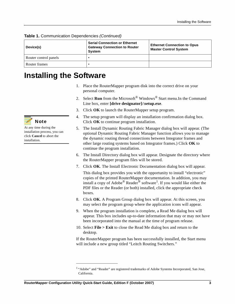
Installing the Software
Installing the Software1. Place the RouterMapper program disk into the correct drive on your
personal computer.
2. Select Run from the Microsoft® Windows® Start menu.In the Command Line box, enter [drive designator]:\setup.exe.
3. Click OK to launch the RouterMapper setup program.
4. The setup program will display an installation confirmation dialog box. Click OK to continue program installation.
5. The Install Dynamic Routing Fabric Manager dialog box will appear. (The optional Dynamic Routing Fabric Manager function allows you to manage the dynamic routing thread connections between Integrator frames and other large routing systems based on Integrator frames.) Click OK to continue the program installation.
6. The Install Directory dialog box will appear. Designate the directory where the RouterMapper program files will be stored.
7. Click OK. The Install Electronic Documentation dialog box will appear.This dialog box provides you with the opportunity to install “electronic” copies of the printed RouterMapper documentation. In addition, you may install a copy of Adobe® Reader® software1. If you would like either the PDF files or the Reader (or both) installed, click the appropriate check boxes.
8. Click OK. A Program Group dialog box will appear. At this screen, you may select the program group where the application icons will appear.
9. When the program installation is complete, a Read Me dialog box will appear. This box includes up-to-date information that may or may not have been incorporated into the manual at the time of program release.
10. Select File > Exit to close the Read Me dialog box and return to the desktop.
If the RouterMapper program has been successfully installed, the Start menu will include a new group titled “Leitch Routing Switchers.”
Router control panels •
Router frames •
Table 1. Communication Dependencies (Continued)
Device(s)Serial Connection or Ethernet Gateway Connection to Router System
Ethernet Connection to Opus Master Control System
NoteAt any time during the installation process, you can click Cancel to abort the installation.
1 “Adobe” and “Reader” are registered trademarks of Adobe Systems Incorporated, San Jose, California.

4 RouterMapper Configuration Utility Quick-Start Guide, Edition F (October 2007)
RouterMapper Quick-Start Guide
Installing RouterMapper on PCs Using Microsoft® Windows® Me Operating System
If you want to install RouterMapper on a PC that uses a Windows Me operating system, you may need to manually remove the following files and Windows registry entries.
Files and Directories1. At the Leitch root directory (C:\Leitch)
a. Move any previously-created databases that you want to save to another location.
b. Move any previously-created PAN files that you want to save to another location.
c. Delete all files and subdirectories.2. At the Windows root directory (C:\Windows [or WINNT, etc.])
a. Move the EDITRTR.INI file that you want to save to another location.b. Delete EDITRTR.INI file in the Windows root directory.
Registry EntriesUse REGEDIT to remove the following key, sub-keys and values: HKEY_CURRENT_USER\Software\Leitch Routers and Switchers
Connecting RouterMapper to the System• If you are downloading router frame and control panel device
configurations only, you must have a PC that has a serial port connector.• If you are downloading Opus master controller device configurations only,
you must have a PC that has an Ethernet connection.• If you have a CCS Router Gateway, you must have a PC that has an
Ethernet connections (You will connect to a router via the Ethernet gateway.)
• If you are downloading both router frame/control panel and Opus master control device configurations, you must have a PC that has both serial port and Ethernet connections.
To download device configurations, the PC that is running RouterMapper must be connected to a serial port on one of the router frames. Communications between the PC and the panels is carried from the router frame to all of the panels via the X-Y control bus. Figure 1 shows the possible connections.

RouterMapper Configuration Utility Quick-Start Guide, Edition F (October 2007) 5
Installing the Software
Figure 1. Connecting RouterMapper to a Control Panel
Creating an Additional Serial PortIf a serial port is not available on any of the router frames in the system, then an SPT-LSERIAL can be used to provide a serial port for the system. Possible connections are shown in Figure 2.
NoteFor more information on ordering the SPT-LSERIAL, contact your dealer or our Customer Service department.

6 RouterMapper Configuration Utility Quick-Start Guide, Edition F (October 2007)
RouterMapper Quick-Start Guide
Figure 2. Connecting RouterMapper to Panel via SPT-LSERIAL
Setting Up RouterMapper Software
Controlling Communications SettingsThe Communications Settings dialog box allows you to control various telecommunications devices by changing settings.1. From the RouterMapper main window, click Comm Settings at the
RouterMapper menu bar.2. Choose one of these selections:

RouterMapper Configuration Utility Quick-Start Guide, Edition F (October 2007) 7
Creating a RouterMapper Database
• If you have a direct serial connection type, you can change baud rate or comm port settings.
• If you have a remote dial-up connection type, you can set the baud rate for your modem, the remote router telephone number, automatic redialing properties, tone or pulse dialing mode, and your modem initialization string.
• If you have a TCP/IP connection type, you can set the IP address connections and give instructions on what to do if a current IP address connection fails.
• If your PC is not connected to a routing system, but you want to see how RouterWorks software will operate with a routing system, choose Demo Mode to simulate the presence of a router and will allow the RouterWorks software to be operated normally.
Setting PreferencesThe Preferences dialog box allows you to control how particular aspects of RouterMapper information is displayed. To access the Preferences dialog box:1. From the RouterMapper main window, click Preferences at the
RouterMapper menu bar.2. Choose one of these selections:
• Editor (allows you to display certain kinds of helpful information when you edit router databases or panel settings)
• Panel Defaults (provides the default button definition for all panels’ two auxiliary buttons)
• Soft Panel Fonts (allows you to select the fonts to use on soft panel and hard panel displays)
• Hard Panel Fonts (allows you to select the fonts to use on soft panel and hard panel displays)
• Button Color (allows you to change panel button background color and panel button text color; and to select color printing for key caps)
• Zero-Based Export (allows you to controls whether you export a RouterMapper database with zero-based or one-based numbers)
Creating a RouterMapper Database1. Poll the system for frames, control panels, and master controllers; discover
them; or add them manually (see “Polling the Control System,” starting on page 50; “Discovering Devices,” starting on page 58, and “Adding Devices Manually,” starting on page 60 of your RouterMapper Configuration Utility manual).
NoteDetailed instructions on setting up a remote dial-up connection are provided in “Remote Dial-Up,” starting on page 25 of your RouterMapper Configuration Utility manual. A copy of the manual is available on your setup disk.

8 RouterMapper Configuration Utility Quick-Start Guide, Edition F (October 2007)
RouterMapper Quick-Start Guide
2. Edit the frames. Set the levels, source offsets and destination offsets, etc. (see “Editing a Frame Definition,” starting on page 287 of your RouterMapper Configuration Utility manual; for Opus master control switchers see “Selecting a Master Control Frame” starting on page 3 of your RouterMapper-Opus Configuration Utility manual).
3. Edit the logical database. Define the logical sources, logical destinations, etc. (see “Editing a Logical Database,” starting on page 217 of your RouterMapper Configuration Utility manual).
4. Configure the control panels (see the table of contents of your RouterMapper Configuration Utility manual for your particular panel; for Opus master control switchers see “Editing an Opus Panel” starting on page 55 of your RouterMapper-Opus Configuration Utility manual).
5. Download all frames and control panels (see “Downloading Device Definitions,” starting on page 65 of your RouterMapper Configuration Utility manual).
Special Information About Setting up Platinum Communications Settings
IMPORTANT: The ENET 1 and ENET 2 tabs control the Ethernet ports on your Platinum router. The configuration steps you follow will differ, depending on whether you use one or both ports.The ENET 1 and the ENET 2 tabs’ network properties are divided into two sections: the Current (read-only) section, which is displayed on the left side of Figure 1-1/Figure 1-2; and the Programmed (editable) settings section, which is displayed on the right side of Figure 1-1/Figure 1-2.
Programmed settings include• Frame IP address (this is necessary for transferring or upgrading files via
an FTP site; the actual frame IP address is set up via Navigator or card-edge controls.)
• Gateway address• Subnet Mask address
NoteYou cannot change the MAC address at this tab. The MAC address is set up via Navigator or card-edge controls.

RouterMapper Configuration Utility Quick-Start Guide, Edition F (October 2007) 9
Special Information About Setting up Platinum Communications Settings
Figure 1-1. ENET 1 Tab Showing Current and Programmed Selection Results
Figure 1-2. ENET 2 Tab Showing Current and Programmed Selection Results
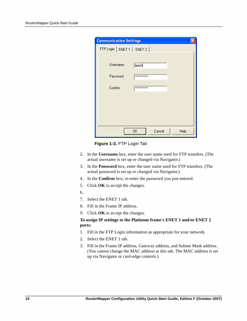
To set up communication for RouterMapper to transfer configuration files to the Platinum frame (this is not assigning an IP address to the frame):1. In the Platinum Communications Settings box, click Settings.... The
Communication Settings dialog box will appear.If necessary, select the FTP Login tab.
10 RouterMapper Configuration Utility Quick-Start Guide, Edition F (October 2007)
RouterMapper Quick-Start Guide
Figure 1-3. FTP Login Tab
2. In the Username box, enter the user name used for FTP transfers. (The actual username is set up or changed via Navigator.)
3. In the Password box, enter the user name used for FTP transfers. (The actual password is set up or changed via Navigator.)
4. In the Confirm box, re-enter the password you just entered.5. Click OK to accept the changes.6.7. Select the ENET 1 tab.8. Fill in the Frame IP address.9. Click OK to accept the changes.To assign IP settings to the Platinum frame's ENET 1 and/or ENET 2 ports:1. Fill in the FTP Login information as appropriate for your network.2. Select the ENET 1 tab.3. Fill in the Frame IP address, Gateway address, and Subnet Mask address.
(You cannot change the MAC address at this tab. The MAC address is set up via Navigator or card-edge controls.)
RouterMapper Configuration Utility Quick-Start Guide, Edition F (October 2007) 11
Special Information about Setting up an Opus Master Control Switcher
4. Select the ENET 2 tab. 5. Select the Check to modify network settings for this port check box.6. Fill in the Frame IP address, Gateway address, and Subnet Mask address.7. Click Download to accept the changes and send the changes to the router.
You will receive a series of informational messages showing the progress of the download.
Special Information about Setting up an Opus Master Control Switcher
The Opus master control switcher uses Ethernet-based communication. The default IP addresses will function correctly in one frame and one control panel configuration. We recommend that the PC used for configuration, the control panel, and the frame should all be connected directly to the hub and that the hub is not connected to a network server/ router. If you must connect this system to an additional network, please contact Customer Service for more detailed information.• The Opus master control switcher also supports external router control. If
the external router control functionality is used, the router configuration should be downloaded through the serial port to the target Opus master control frame after the Opus master control frame configuration has been successfully downloaded through your Ethernet connection. See “Controlling an External Router” starting on page 45 of your RouterMapper-Opus Configuration Utility manual, for details.
• To change network configuration of an Opus frame, see page 7 in your RouterMapper-Opus Configuration Utility manual.
• To change network configuration of an Opus control panel, see page 7 in your RouterMapper-Opus Configuration Utility. Also see “Setting up Network Information” starting on page 57 of your RouterMapper-Opus Configuration Utility manual.
• To make a configuration of multiple frames and panels, see “Editing the Master Assignment Window” starting on page 60 of your RouterMapper-Opus Configuration Utility manual.
Opus Ethernet Communication Error and DiagnosisA network communication error occurred if the Download Abort - Communication Error message appears.
NoteThe ENET 2 port is disabled by default; you will need to make changes only if you are using a second Ethernet port on a Platinum router.
If the IP address you changed from is already set up in the Comm Settings menu, this download will change the selection at the RouterMapper Comm Settings menu. If the IP Address you changed from is not already set up, this download will not add the selection to the list.

12 RouterMapper Configuration Utility Quick-Start Guide, Edition F (October 2007)
RouterMapper Quick-Start Guide
If a communication error occurred, you need to check the physical network link between the PC and the target frame or the target panel. The following method can be used to verify network communication condition.
Verify Network Communication by Using PingUnder a DOS prompt, try the following command to clarify whether there is a network problem. ping <Current Frame IP Address>; then, click Enter.
Example 1: Ping response for a good network link Example 1 shows what will be displayed if testing communication with a frame that has the IP address 172.16.10.210.
C:\WINDOWS>ping 172.16.10.210Pinging 172.16.10.210 with 32 bytes of data:Reply from 172.16.10.210: bytes=32 time=2ms TTL=255 Reply from 172.16.10.210: bytes=32 time=1ms TTL=255 Reply from 172.16.10.210: bytes=32 time=1ms TTL=255 Reply from 172.16.10.210: bytes=32 time=1ms TTL=255Ping statistics for 172.16.10.210:Packets: Sent = 4, Received = 4, Lost = 0 (0% loss),Approximate round trip times in milliseconds:Minimum = 1ms, Maximum = 2ms, Average = 1ms
Example 2: Ping response for a bad network link Example 2 shows what will be displayed if there is a bad network link to a frame that has the IP address 172.16.10.210.
C:\WINDOWS>ping 172.16.10.210Pinging 172.16.10.210 with 32 bytes of data:Request timed out. Request timed out. Request timed out. Request timed out. Ping statistics for 172.16.10.210:Packets: Sent = 4, Received = 0, Lost = 4 (100% loss),Approximate round trip times in milliseconds:Minimum = 0ms, Maximum = 0ms, Average = 0ms
Persistent Communication Errors If Ping <Current Frame IP Address> shows a good physical link but the communication errors persist:1. Reboot the target frame.2. Close and reopen the RouterMapper program.

RouterMapper Configuration Utility Quick-Start Guide, Edition F (October 2007) 13
Contacting Us
Contacting UsIf you have questions about this or other any of our other products, contact us for technical support and product information.
Technical SupportWe are committed to providing round-the-clock, 24-hour service to our customers around the world. Visit our website for information on how to contact the Customer Service team in your geographical region.
Product InformationIf you would like the latest product information or documentation, contact your dealer or our Sales Department; or, visit our website for more information.

14 RouterMapper Configuration Utility Quick-Start Guide, Edition F (October 2007)
RouterMapper Quick-Start Guide