rov control systems - cesos - ntnu dukan.pdf · rov control systems cesos highlights and amos...
TRANSCRIPT
1
ROV Control Systems
CeSOS Highlights and AMOS Visions
Trondheim, 27-29th May 2013
Fredrik Dukan
Centre for Autonomous Marine Operations (AMOS), Department of Marine Technology, NTNU
2
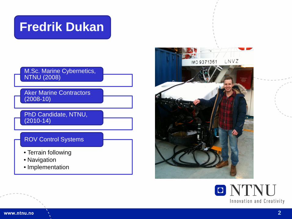
Fredrik Dukan
M.Sc. Marine Cybernetics, NTNU (2008)
Aker Marine Contractors (2008-10)
PhD Candidate, NTNU, (2010-14)
• Terrain following • Navigation • Implementation
ROV Control Systems
3
Outline
Motivation & Challenges
• Actuators & Sensors
ROV System
• Architechture • Navigation, Guidance & Control • Implementation
Control System
• ROV Minerva & 30k
Full Scale Tests
4
Motivation, ROV Control System:
• Safety • Performance & Consistency • Time & Cost
Automate underwater operations
• Biology • Geology • Archeology • Oil & gas
Add value to other fields
5
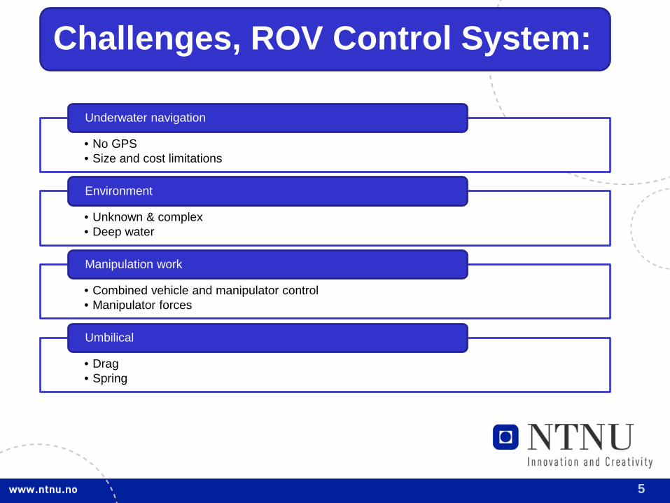
Challenges, ROV Control System:
• No GPS • Size and cost limitations
Underwater navigation
• Unknown & complex • Deep water
Environment
• Combined vehicle and manipulator control • Manipulator forces
Manipulation work
• Drag • Spring
Umbilical
6
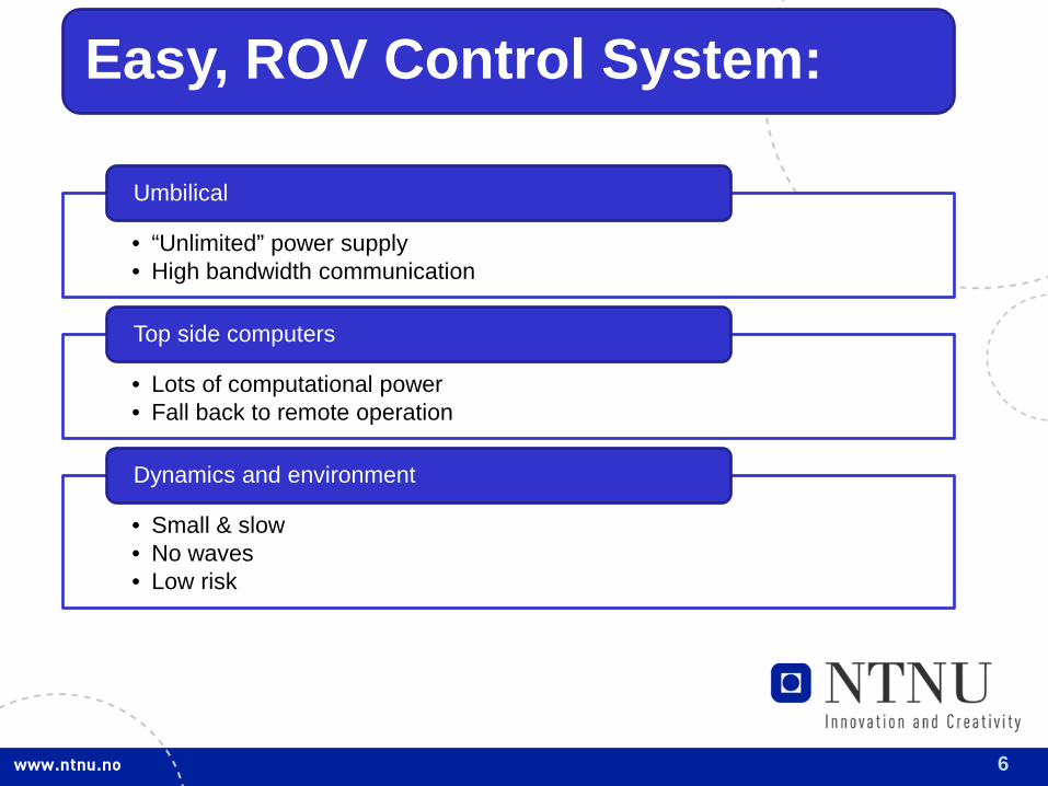
Easy, ROV Control System:
• “Unlimited” power supply • High bandwidth communication
Umbilical
• Lots of computational power • Fall back to remote operation
Top side computers
• Small & slow • No waves • Low risk
Dynamics and environment
7
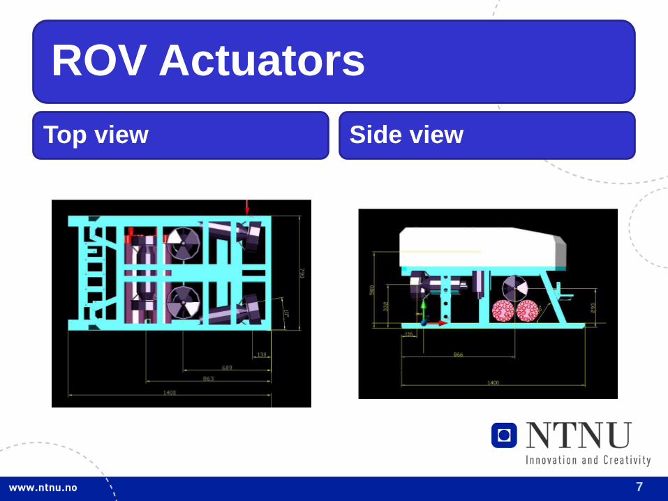
ROV Actuators Top view Side view
8
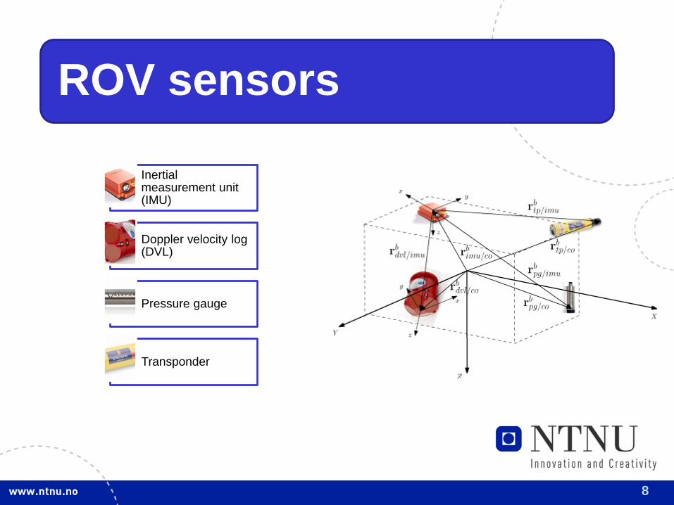
ROV sensors
Inertial measurement unit (IMU)
Doppler velocity log (DVL)
Pressure gauge
Transponder
9
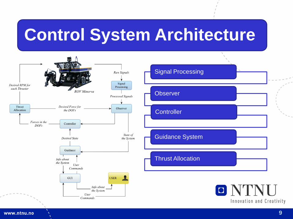
Control System Architecture
Signal Processing
Observer
Controller
Guidance System
Thrust Allocation
10
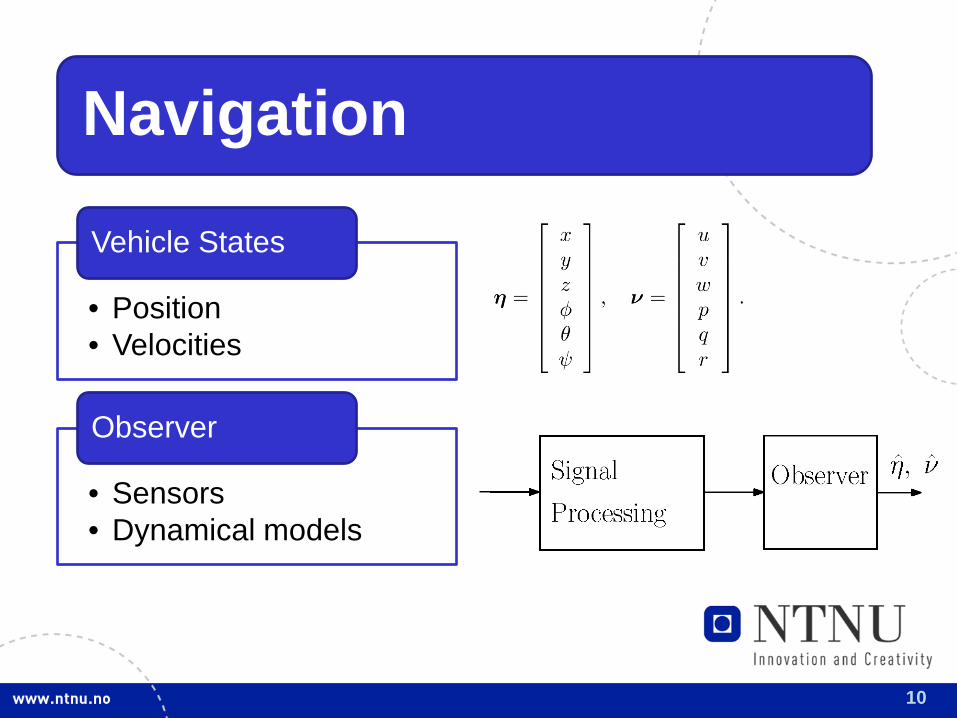
Navigation
• Position • Velocities
Vehicle States
• Sensors • Dynamical models
Observer
11
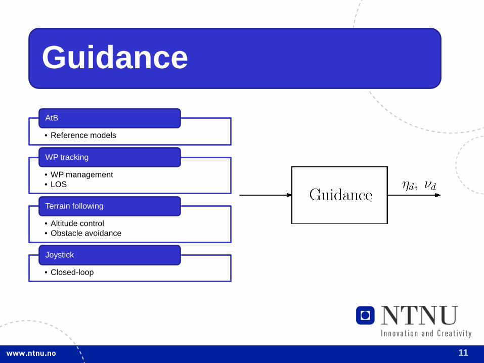
Guidance
• Reference models
AtB
• WP management • LOS
WP tracking
• Altitude control • Obstacle avoidance
Terrain following
• Closed-loop
Joystick
12
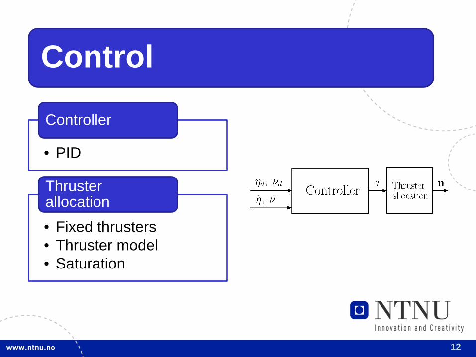
Control
• PID
Controller
• Fixed thrusters • Thruster model • Saturation
Thruster allocation
13
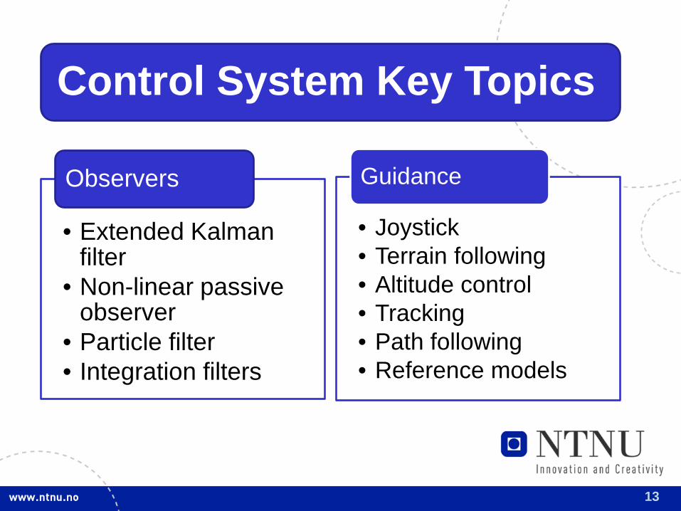
Control System Key Topics
• Extended Kalman filter
• Non-linear passive observer
• Particle filter • Integration filters
Observers
• Joystick • Terrain following • Altitude control • Tracking • Path following • Reference models
Guidance
14
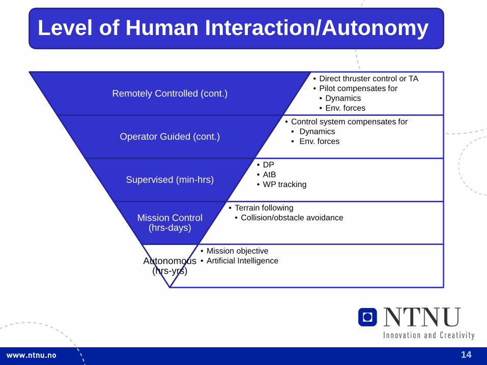
Level of Human Interaction/Autonomy
• Direct thruster control or TA • Pilot compensates for
• Dynamics • Env. forces
Remotely Controlled (cont.)
• Control system compensates for • Dynamics • Env. forces Operator Guided (cont.)
• DP • AtB • WP tracking Supervised (min-hrs)
• Terrain following • Collision/obstacle avoidance Mission Control
(hrs-days)
• Mission objective • Artificial Intelligence Autonomous
(hrs-yrs)
15
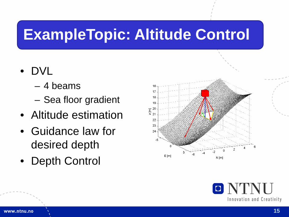
ExampleTopic: Altitude Control
• DVL – 4 beams – Sea floor gradient
• Altitude estimation • Guidance law for
desired depth • Depth Control
16
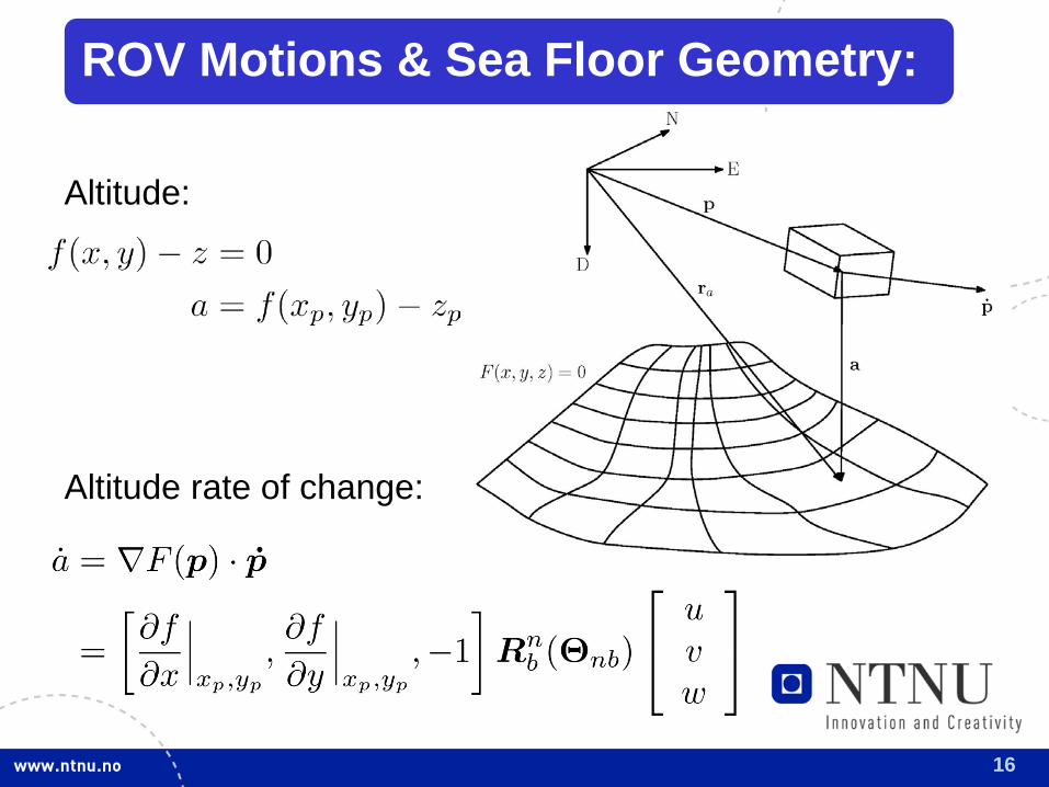
ROV Motions & Sea Floor Geometry:
Altitude rate of change:
Altitude:
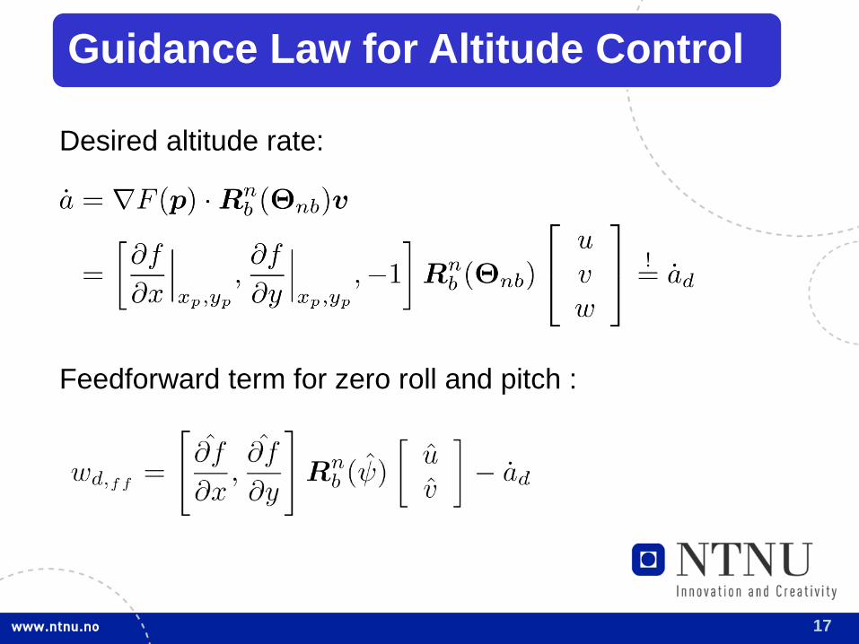
17
Guidance Law for Altitude Control
Desired altitude rate:
Feedforward term for zero roll and pitch :
18
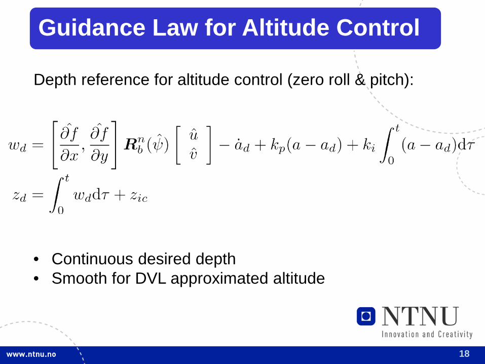
Guidance Law for Altitude Control
Depth reference for altitude control (zero roll & pitch):
• Continuous desired depth • Smooth for DVL approximated altitude
19
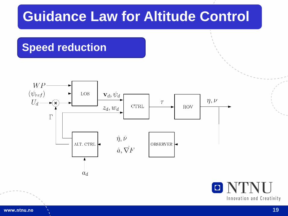
Guidance Law for Altitude Control
Speed reduction
20
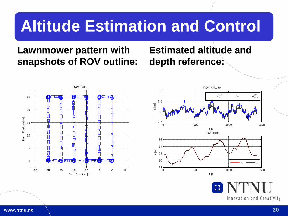
Altitude Estimation and Control Lawnmower pattern with snapshots of ROV outline:
-30 -25 -20 -15 -10 -5 0 5
0
5
10
15
20
25
East Position [m]
ROV Trace
Nor
th P
ositi
on [m
]
Estimated altitude and depth reference:
0 500 1000 15004.5
5
5.5
6ROV Altitude
t [s]
a [m
]
aCOd
am aCOavg
0 500 1000 150078
80
82
84
86
ROV Depth
t [s]
z [m
]
zd z
21
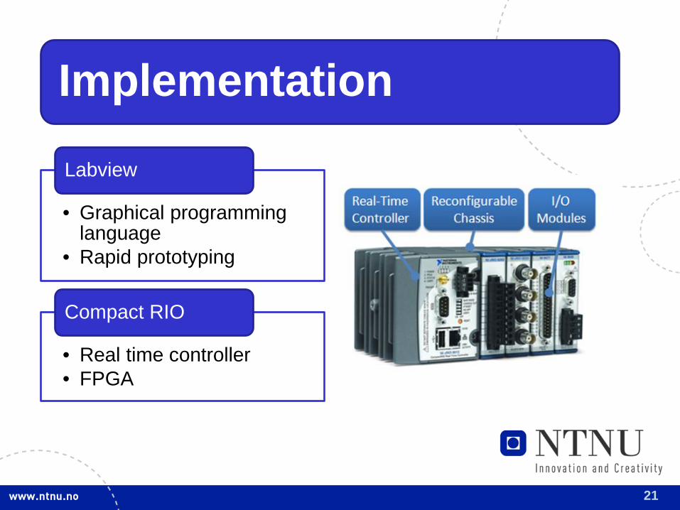
Implementation
• Graphical programming language
• Rapid prototyping
Labview
• Real time controller • FPGA
Compact RIO
22
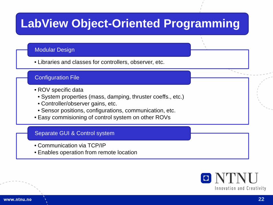
LabView Object-Oriented Programming
• Libraries and classes for controllers, observer, etc.
Modular Design
• ROV specific data • System properties (mass, damping, thruster coeffs., etc.) • Controller/observer gains, etc. • Sensor positions, configurations, communication, etc.
• Easy commisioning of control system on other ROVs
Configuration File
• Communication via TCP/IP • Enables operation from remote location
Separate GUI & Control system
23
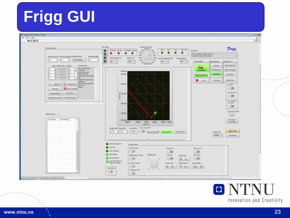
Frigg GUI
24
Experiences from the Field
• Matlab • Tested on Minerva • Early test stage
First DP in 2010
• Labview • ROV as test bed/instrument platform • Tested on 30k • Operational
New Control System in 2012
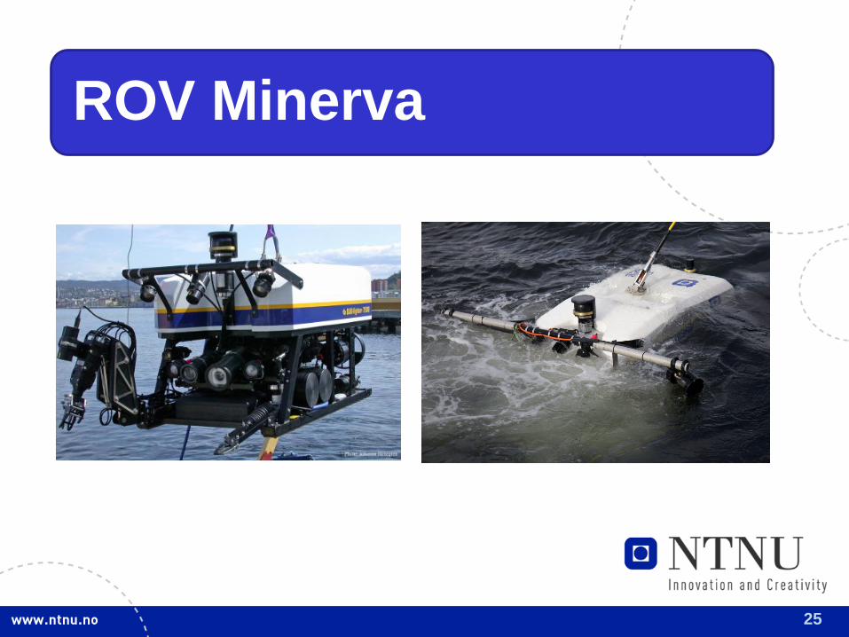
25
ROV Minerva
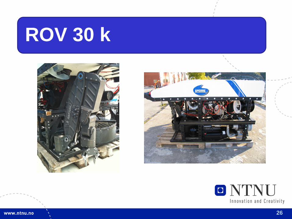
26
ROV 30 k
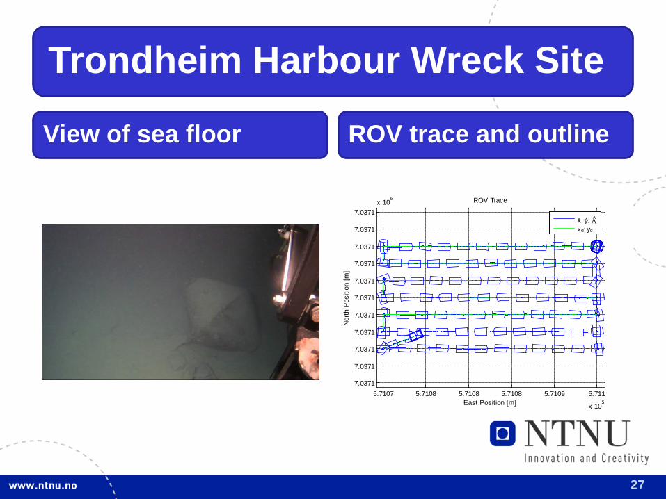
27
Trondheim Harbour Wreck Site
View of sea floor ROV trace and outline
5.7107 5.7108 5.7108 5.7108 5.7109 5.711
x 105
7.0371
7.0371
7.0371
7.0371
7.0371
7.0371
7.0371
7.0371
7.0371
7.0371
7.0371x 10
6
East Position [m]
ROV Trace
Nor
th P
ositi
on [m
]
x; y; Axd; yd
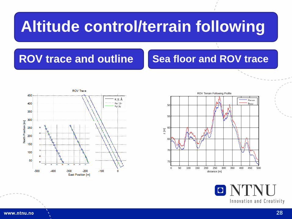
28
Altitude control/terrain following
ROV trace and outline Sea floor and ROV trace
0 50 100 150 200 250 300 350 400 450 500
50
55
60
65
70
75
ROV Terrain Following Profile
distance [m]
z [m
]
zter rain
zROV
29
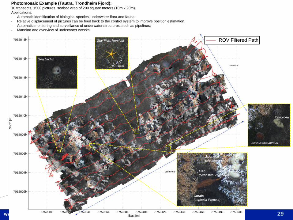
Photomosaic Example (Tautra, Trondheim Fjord): 10 transects, 1500 pictures, seabed area of 200 square meters (10m x 20m). Applications: - Automatic identification of biological species, underwater flora and fauna; - Relative displacement of pictures can be feed back to the control system to improve position estimation. - Automatic monitoring and surveillance of underwater structures, such as pipelines; - Mapping and overview of underwater wrecks.
Corals (Lopheila Pertusa)
Fish (Sebastes Viviparus)
Sponges (Mycale Lingua)
Sea Urchin
Star Fish: Henricia
Echinus esculentus
Crinoidea
10cm
ROV Filtered Path
30
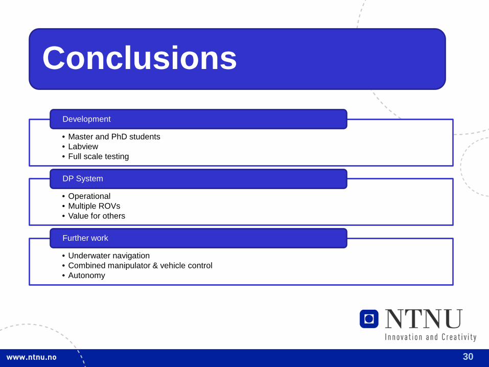
Conclusions
• Master and PhD students • Labview • Full scale testing
Development
• Operational • Multiple ROVs • Value for others
DP System
• Underwater navigation • Combined manipulator & vehicle control • Autonomy
Further work