rowlinson gainsborough gazebo ss171
DESCRIPTION
ÂTRANSCRIPT
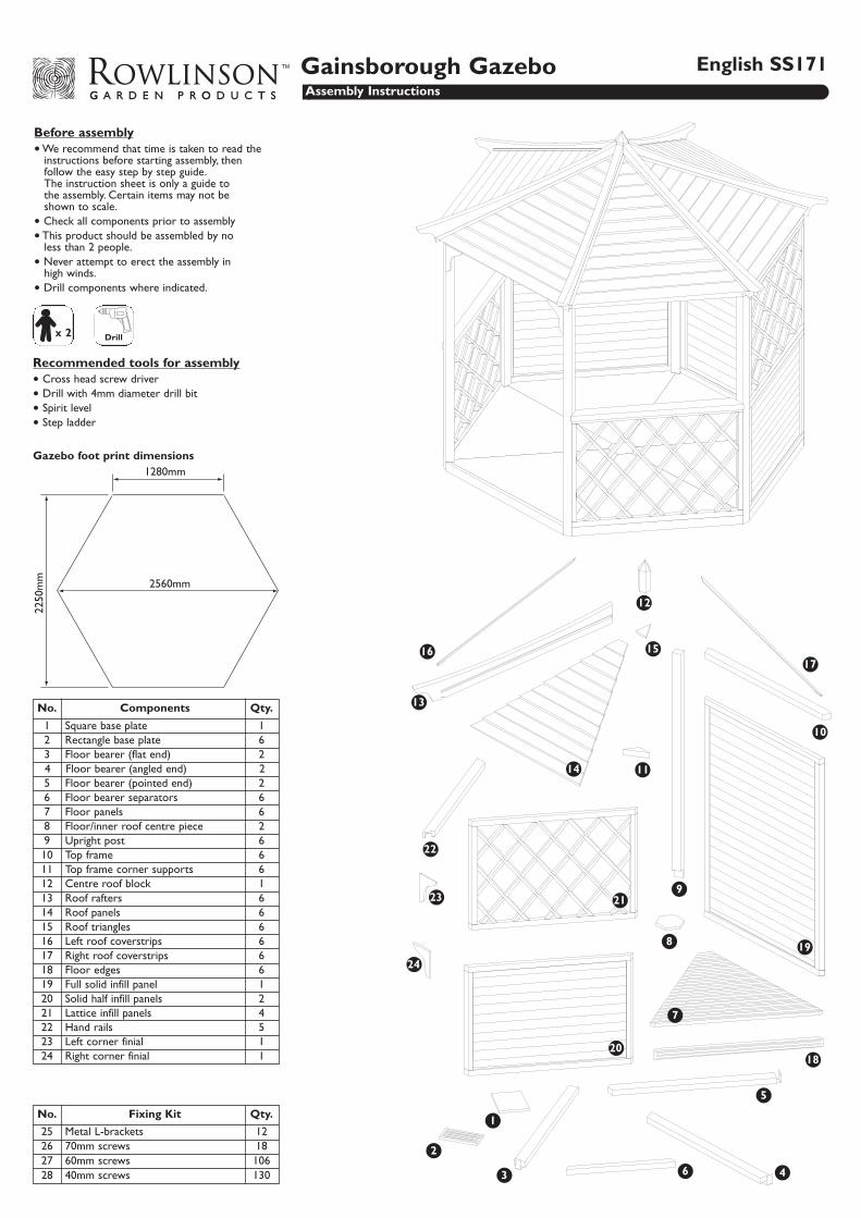
Before assembly• We recommend that time is taken to read the
instructions before starting assembly, then follow the easy step by step guide.The instruction sheet is only a guide to the assembly. Certain items may not be shown to scale.
• Check all components prior to assembly• This product should be assembled by no
less than 2 people.• Never attempt to erect the assembly in
high winds.• Drill components where indicated.
x 2 Drill
Recommended tools for assembly• Cross head screw driver • Drill with 4mm diameter drill bit• Spirit level • Step ladder
No. Components Qty.
1 Square base plate 12 Rectangle base plate 63 Floor bearer (flat end) 24 Floor bearer (angled end) 25 Floor bearer (pointed end) 26 Floor bearer separators 67 Floor panels 68 Floor/inner roof centre piece 29 Upright post 610 Top frame 611 Top frame corner supports 612 Centre roof block 1
No. Fixing Kit Qty.
25 Metal L-brackets 1226 70mm screws 1827 60mm screws 10628 40mm screws 130
1
2
3
13
6
8
5
4
7
11
10
9
Gainsborough Gazebo English SS171Assembly Instructions
14
24
1617
18
19
20
21
22
23
12
13 Roof rafters 614 Roof panels 615 Roof triangles 616 Left roof coverstrips 617 Right roof coverstrips 618 Floor edges 619 Full solid infill panel 120 Solid half infill panels 221 Lattice infill panels 422 Hand rails 523 Left corner finial 124 Right corner finial 1
15
1280mm
2560mm
2250
mm
Gazebo foot print dimensions
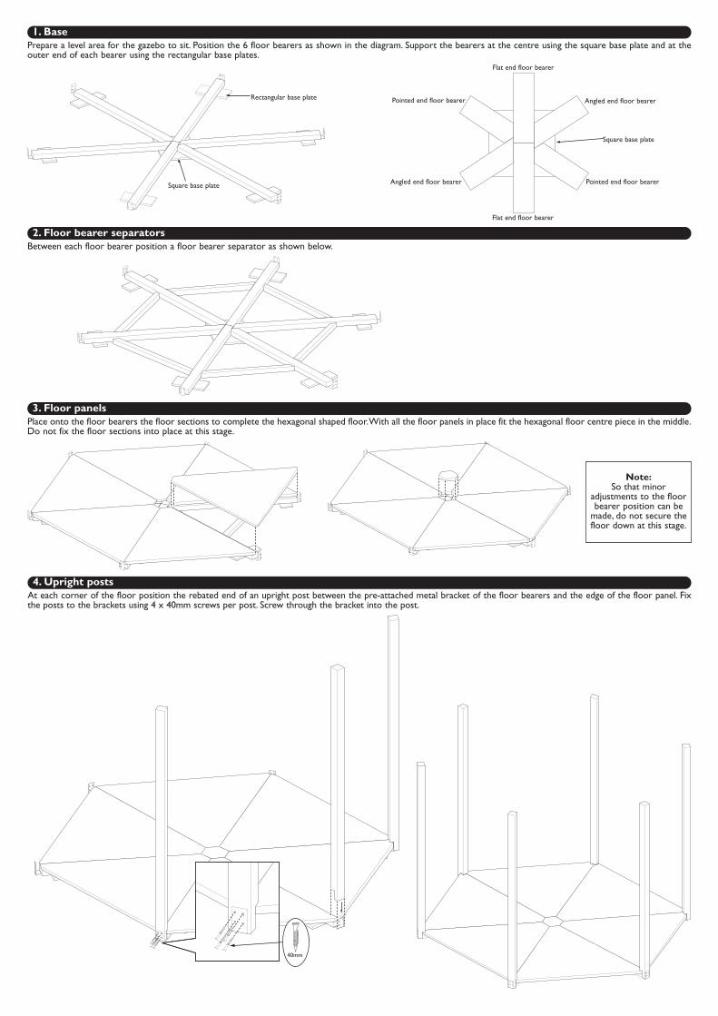
1. BasePrepare a level area for the gazebo to sit. Position the 6 floor bearers as shown in the diagram. Support the bearers at the centre using the square base plate and at theouter end of each bearer using the rectangular base plates.
2. Floor bearer separatorsBetween each floor bearer position a floor bearer separator as shown below.
40mm
Square base plate
Rectangular base plate
Square base plate
Flat end floor bearer
Angled end floor bearer
Pointed end floor bearerAngled end floor bearer
Flat end floor bearer
Pointed end floor bearer
Note:So that minor
adjustments to the floorbearer position can be
made, do not secure thefloor down at this stage.
3. Floor panelsPlace onto the floor bearers the floor sections to complete the hexagonal shaped floor.With all the floor panels in place fit the hexagonal floor centre piece in the middle.Do not fix the floor sections into place at this stage.
4. Upright postsAt each corner of the floor position the rebated end of an upright post between the pre-attached metal bracket of the floor bearers and the edge of the floor panel. Fixthe posts to the brackets using 4 x 40mm screws per post. Screw through the bracket into the post.
70mm
Drill
Drill a 4mmpilot hole foreach screw.
60mm
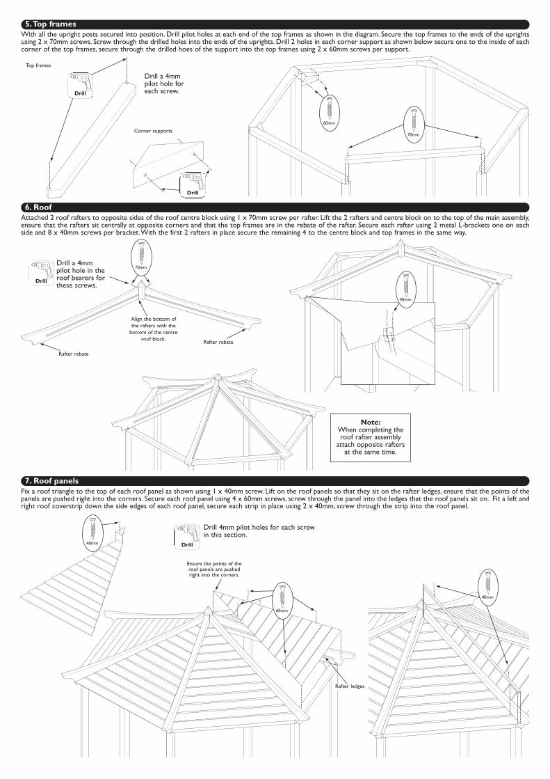
5.Top framesWith all the upright posts secured into position. Drill pilot holes at each end of the top frames as shown in the diagram. Secure the top frames to the ends of the uprightsusing 2 x 70mm screws. Screw through the drilled holes into the ends of the uprights. Drill 2 holes in each corner support as shown below secure one to the inside of eachcorner of the top frames, secure through the drilled hoes of the support into the top frames using 2 x 60mm screws per support.
Drill
Top frames
Corner supports
70mm
Align the bottom ofthe rafters with the
bottom of the centreroof block.
40mm
Rafter rebate
40mm
60mm
Rafter ledges
Rafter rebate
40mm
Drill
Drill 4mm pilot holes for each screwin this section.
Drill
Drill a 4mmpilot hole in theroof bearers forthese screws.
Note:When completing theroof rafter assembly
attach opposite raftersat the same time.
Ensure the points of theroof panels are pushedright into the corners.
6. RoofAttached 2 roof rafters to opposite sides of the roof centre block using 1 x 70mm screw per rafter. Lift the 2 rafters and centre block on to the top of the main assembly,ensure that the rafters sit centrally at opposite corners and that the top frames are in the rebate of the rafter. Secure each rafter using 2 metal L-brackets one on eachside and 8 x 40mm screws per bracket.With the first 2 rafters in place secure the remaining 4 to the centre block and top frames in the same way.
7. Roof panelsFix a roof triangle to the top of each roof panel as shown using 1 x 40mm screw. Lift on the roof panels so that they sit on the rafter ledges, ensure that the points of thepanels are pushed right into the corners. Secure each roof panel using 4 x 60mm screws, screw through the panel into the ledges that the roof panels sit on. Fit a left andright roof coverstrip down the side edges of each roof panel, secure each strip in place using 2 x 40mm, screw through the strip into the roof panel.
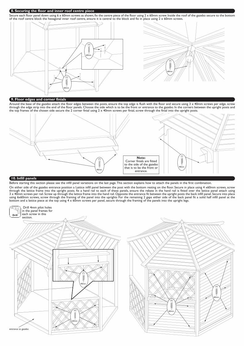
8. Securing the floor and inner roof centre pieceSecure each floor panel down using 6 x 60mm screws as shown, fix the centre piece of the floor using 2 x 60mm screw. Inside the roof of the gazebo secure to the bottomof the roof centre block the hexagonal inner roof centre, ensure it is central to the block and fix in place using 2 x 60mm screws.
60mm
60mm
60mm
60mm
60mm
60mm
9. Floor edges and corner finialsAround the base of the gazebo attach the floor edges between the posts, ensure the top edge is flush with the floor and secure using 3 x 40mm screws per edge, screwthrough the edge strip into the end of the floor panels. Choose the side which is to be the front or entrance to the gazebo. In the corners between the upright posts andthe top frames of the chosen side secure the 2 corner finial using 2 x 40mm screws per finial, screw through the finial into the upright posts.
40mm40mm
Note:Corner finials are fitted
to the side of the gazebothat is to be the front or
entrance.
Drill
Drill 4mm pilot holesin the panel frames foreach screw in thissection.
40mm
10. Infill panelsBefore starting this section please see the infill panel variations on the last page.This section explains how to attach the panels in the first combination.On either side of the gazebo entrance position a Lattice infill panel between the post with the bottom resting on the floor. Secure in place using 4 x60mm screws, screwthrough the lattice frame into the upright posts. fix a hand rail to each of these panels, ensure the rebate in the hand rail is fitted over the lattice panel attach using3 x 40mm screws per rail. Screw up through the lattice frame into the hand rail. Opposite the entrance fit between the upright posts the back infill panel. Secure into placeusing 6x60mm screws, screw through the framing of the panel into the uprights For the remaining 2 gaps either side of the back panel fit a solid half infill panel at thebottom and a lattice piece at the top using 4 x 60mm screws per panel, secure through the framing of the panels into the upright legs.
entrance to gazebo
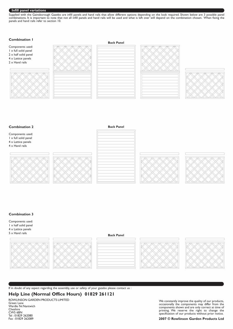
Infill panel variationsSupplied with the Gainsborough Gazebo are infill panels and hand rails that allow different options depending on the look required. Shown below are 3 possible panelcombinations. It is important to note that not all infill panels and hand rails will be used and what is left over will depend on the combination chosen. When fixing thepanels and hand rails refer to section 10.
Combination 1
Components used:1 x full solid panel2 x half solid panel4 x Lattice panels2 x Hand rails
Combination 2
Components used:1 x full solid panel4 x Lattice panels4 x Hand rails
Combination 3
Components used:1 x half solid panel4 x Lattice panels5 x Hand rails
2007 © Rowlinson Garden Products Ltd
We constantly improve the quality of our products,occasionally the components may differ from thecomponents shown and are only correct at time ofprinting. We reserve the right to change thespecification of our products without prior notice.
If in doubt of any aspect regarding the assembly, use or safety of your gazebo please contact us :
Help Line (Normal Office Hours) 01829 261121ROWLINSON GARDEN PRODUCTS LIMITEDGreen Lane Wardle Nr.NantwichCheshireCW5 6BNTel : 01829 262080Fax : 01829 262089
Back Panel
Back Panel
Back Panel