roy m. sullivan, louis j. ghosn and bradley a. lerch- an elongated tetrakaidecahedron model for...
TRANSCRIPT

8/3/2019 Roy M. Sullivan, Louis J. Ghosn and Bradley A. Lerch- An Elongated Tetrakaidecahedron Model for Open-Celled Foams
http://slidepdf.com/reader/full/roy-m-sullivan-louis-j-ghosn-and-bradley-a-lerch-an-elongated-tetrakaidecahedron 1/32
Roy M. Sullivan
Glenn Research Center, Cleveland, Ohio
Louis J. Ghosn
Ohio Aerospace Institute, Brook Park, Ohio
Bradley A. Lerch
Glenn Research Center, Cleveland, Ohio
An Elongated Tetrakaidecahedron Model for Open-Celled Foams
NASA/TM—2007-214931
July 2007

8/3/2019 Roy M. Sullivan, Louis J. Ghosn and Bradley A. Lerch- An Elongated Tetrakaidecahedron Model for Open-Celled Foams
http://slidepdf.com/reader/full/roy-m-sullivan-louis-j-ghosn-and-bradley-a-lerch-an-elongated-tetrakaidecahedron 2/32
NASA STI Program . . . in Profile
Since its founding, NASA has been dedicated to the
advancement of aeronautics and space science. The NASA Scientific and Technical Information (STI)
program plays a key part in helping NASA maintain
this important role.
The NASA STI Program operates under the auspices
of the Agency Chief Information Officer. It collects,
organizes, provides for archiving, and disseminates
NASA’s STI. The NASA STI program provides access
to the NASA Aeronautics and Space Database and its
public interface, the NASA Technical Reports Server,
thus providing one of the largest collections of
aeronautical and space science STI in the world.Results are published in both non-NASA channels and
by NASA in the NASA STI Report Series, which
includes the following report types:
• TECHNICAL PUBLICATION. Reports of
completed research or a major significant phase
of research that present the results of NASA
programs and include extensive data or theoretical
analysis. Includes compilations of significant
scientific and technical data and information
deemed to be of continuing reference value.
NASA counterpart of peer-reviewed formal professional papers but has less stringent
limitations on manuscript length and extent of
graphic presentations.
• TECHNICAL MEMORANDUM. Scientific
and technical findings that are preliminary or
of specialized interest, e.g., quick release
reports, working papers, and bibliographies that
contain minimal annotation. Does not contain
extensive analysis.
• CONTRACTOR REPORT. Scientific and
technical findings by NASA-sponsored
contractors and grantees.
• CONFERENCE PUBLICATION. Collected
papers from scientific and technicalconferences, symposia, seminars, or other
meetings sponsored or cosponsored by NASA.
• SPECIAL PUBLICATION. Scientific,
technical, or historical information from
NASA programs, projects, and missions, often
concerned with subjects having substantial
public interest.
• TECHNICAL TRANSLATION. English-
language translations of foreign scientific and
technical material pertinent to NASA’s mission.
Specialized services also include creating custom
thesauri, building customized databases, organizing
and publishing research results.
For more information about the NASA STI
program, see the following:
• Access the NASA STI program home page at
http://www.sti.nasa.gov
• E-mail your question via the Internet [email protected]
• Fax your question to the NASA STI Help Desk
at 301–621–0134
• Telephone the NASA STI Help Desk at
301–621–0390
• Write to:
NASA Center for AeroSpace Information (CASI)
7115 Standard Drive
Hanover, MD 21076–1320

8/3/2019 Roy M. Sullivan, Louis J. Ghosn and Bradley A. Lerch- An Elongated Tetrakaidecahedron Model for Open-Celled Foams
http://slidepdf.com/reader/full/roy-m-sullivan-louis-j-ghosn-and-bradley-a-lerch-an-elongated-tetrakaidecahedron 3/32
National Aeronautics and
Space Administration
Glenn Research Center
Cleveland, Ohio 44135
Roy M. Sullivan
Glenn Research Center, Cleveland, Ohio
Louis J. Ghosn
Ohio Aerospace Institute, Brook Park, Ohio
Bradley A. Lerch
Glenn Research Center, Cleveland, Ohio
An Elongated Tetrakaidecahedron Model for Open-Celled Foams
NASA/TM—2007-214931
July 2007

8/3/2019 Roy M. Sullivan, Louis J. Ghosn and Bradley A. Lerch- An Elongated Tetrakaidecahedron Model for Open-Celled Foams
http://slidepdf.com/reader/full/roy-m-sullivan-louis-j-ghosn-and-bradley-a-lerch-an-elongated-tetrakaidecahedron 4/32
Available from
NASA Center for Aerospace Information
7115 Standard Drive
Hanover, MD 21076–1320
National Technical Information Service
5285 Port Royal Road
Springfield, VA 22161
Available electronically at http://gltrs.grc.nasa.gov
Trade names and trademarks are used in this report for identification
only. Their usage does not constitute an official endorsement,
either expressed or implied, by the National Aeronautics and
Space Administration.
Level of Review: This material has been technically reviewed by technical management.
This report is a formal draft or working
paper, intended to solicit comments and
ideas from a technical peer group.
This report is a preprint of a paper intended for presentation at a conference.Because changes may be made before formal publication, this preprint is made available
with the understanding that it will not be cited or reproduced without
the permission of the author.
Acknowledgments
The authors are grateful for funding from the External Tank Project under NASA’s Space Shuttle Program.
8/3/2019 Roy M. Sullivan, Louis J. Ghosn and Bradley A. Lerch- An Elongated Tetrakaidecahedron Model for Open-Celled Foams
http://slidepdf.com/reader/full/roy-m-sullivan-louis-j-ghosn-and-bradley-a-lerch-an-elongated-tetrakaidecahedron 5/32
NASA/TM—2007-214931 1
An Elongated Tetrakaidecahedron Model for Open-Celled Foams
Roy M. Sullivan
National Aeronautics and Space Administration
Glenn Research Center
Cleveland, Ohio 44135
Louis J. Ghosn
Ohio Aerospace Institute
Brook Park, Ohio 44142
Bradley A. Lerch
National Aeronautics and Space Administration
Glenn Research Center
Cleveland, Ohio 44135
Abstract
A micro-mechanics model for non-isotropic, open-celled foams is developed using an elongated
tetrakaidecahedron (Kelvin model) as the repeating unit cell. The micro-mechanics model employs an
elongated Kelvin model geometry which is more general than that employed by previous authors.
Assuming the cell edges possess axial and bending rigidity, the mechanics of deformation of the
elongated tetrakaidecahedron lead to a set of equations for the Young’s modulus, Poisson’s ratio and
strength of the foam in the principal material directions. These equations are written as a function of the
cell edge lengths and cross-section properties, the inclination angle and the strength and stiffness of the
solid material. The model is applied to predict the strength and stiffness of several polymeric foams. Good
agreement is observed between the model results and the experimental measurements.
1. Introduction
Previous studies on open and closed-cell foams have sought to establish a direct tie between the foam
microstructure and the macro-level foam properties. Through careful consideration of the foam micro-
structure and selection of a suitable representative repeating unit, equations for the foam density, elastic
constants and strength have been written in terms of the micro-structural dimensions and the physical and
mechanical properties of the solid material (Gent and Thomas (1959), Dement’ev and Tarakanov (1970),
and Huber and Gibson (1988)).
To represent the foam micro-structure, many of these previous researchers used a tetrakaidecahedron,
a fourteen-sided polyhedron comprised of six quadrilateral and eight hexagonal faces. Thetetrakaidecahedron is widely known as the Kelvin foam model, as it was Thomson (1887) who, in his
assessment of Plateau’s experiment, identified the tetrakaidecahedron (with slightly curved faces) as the
only polyhedron that packs to fill space and minimize the surface area per unit volume (Gibson and
Ashby (1997)). Zhu, et al. (1997), for example, adopted an equi-axed tetrakaidecahedron to developequations for the foam Young’s modulus, shear modulus and Poisson’s ratio for isotropic, open-celled
foams. They assumed that the mechanical behavior of open-celled foams could be simulated by treating
the edges of the cell faces as structural elements possessing axial, bending and torsional rigidity.
Applying the principle of minimum potential energy to the deformation of the repeating unit, the
equations for the foam elastic constants were written in terms of the cell edge length L, the edge cross-
sectional area A, moment of inertia I and polar moment of inertia J and the Young’s modulus E and shear
modulus G of the solid material. Using a similar set of assumptions, Warren and Kraynik (1997)
developed similar equations for the Young’s modulus, bulk modulus and shear modulus for isotropic,

8/3/2019 Roy M. Sullivan, Louis J. Ghosn and Bradley A. Lerch- An Elongated Tetrakaidecahedron Model for Open-Celled Foams
http://slidepdf.com/reader/full/roy-m-sullivan-louis-j-ghosn-and-bradley-a-lerch-an-elongated-tetrakaidecahedron 6/32
NASA/TM—2007-214931 2
H
D
L
b
θ
θ
L
xy
z
Figure 1.—Elongated tetrakaidecahedron repeating unit cell.
open-celled foams. The more recent model by Gong, et al. (2005a) includes the effect of shear
deformation and allows for the edge cross-sectional area to vary along the length of the edge.
In many cases, the foam micro-structure is elongated in one of the three orthogonal directions causing
the foam mechanical behavior to be non-isotropic. The micro-structure in closed-cell foams, for example,
is often elongated in the rise direction due to the foaming and rising process. To treat non-isotropic
foams, Dement’ev and Tarakanov (1970), Gong, et al. (2005a, b), Ridha, et al. (2006) and others have
adopted an elongated tetrakaidecahedron (fig. 1) as the repeating unit cell, deriving equations for the
elastic constants and strengths in the principal material directions. An elongated tetrakaidecahedron also
packs to fill the space. It contains eight hexagonal faces, two horizontal square faces and four vertical
diamond faces. The horizontal square faces have sides of length b and the diamond faces have sides of
length L. The hexagonal faces have four sides with length L and two sides with length b. The inclination
angle θ defines the orientation of the hexagonal faces with respect to the rise direction as well as the
obtuse angle of the vertical diamond faces.
The size and shape of the elongated tetrakaidecahedron is uniquely defined by specifying the value of
the three dimensions: b, L and θ. The above mentioned authors, however, have developed their equations
for the elastic constants and compressive strengths of non-isotropic foams by imposing the restriction on
the cell geometry that θ= cos2 L
b. This constraint forces the cell shape to be a function of the
inclination angle only. Since, from a purely geometrical point of view, θ and L
bmay vary independently,
we see no reason for this restriction on the cell geometry, other than to reduce the number of micro-
structural measurements required to apply the equations and predict the foam behavior. As such, it is
prudent to revisit the formulation of the previous authors and re-derive the equations for the elastic
constants and strengths using the most general description of the elongated Kelvin model geometry.
In this paper, we derive the equations for the Young’s modulus, Poisson’s ratio and strength for non-isotropic foams in the principal material directions. We follow closely the formulation from Zhu, et al.
(1997), but adopt, as our repeating unit, an elongated Kelvin model with a geometry defined by three
independent dimensions. Furthermore, we allow the edge cross-sections to assume any shape, but restrict
our attention to edge cross-sections that do not vary along the edge length. In the application section, we
make the simplifying approximation that the edge cross-sections are circular and apply the model to
simulate the mechanical and strength behavior of several polymeric foams. In the final section, we extend
the use of the model to closed-cell foams and predict the strength ratio of the five rigid polyurethane
closed-cell foams studied by Huber and Gibson (1988).

8/3/2019 Roy M. Sullivan, Louis J. Ghosn and Bradley A. Lerch- An Elongated Tetrakaidecahedron Model for Open-Celled Foams
http://slidepdf.com/reader/full/roy-m-sullivan-louis-j-ghosn-and-bradley-a-lerch-an-elongated-tetrakaidecahedron 7/32
NASA/TM—2007-214931 3
2. Elongated Tetrakaidecahedron (Kelvin) Model
2.1 Cell Aspect Ratio The size and shape of an elongated tetrakaidecahedron are uniquely defined by specifying the value
of any three of the five dimensions L, b, θ, H , D, since the height H and width D of the unit cell is related
to L, b, and θ according to
θ= sin4 L H and b L D 2cos2 +θ= (1)
The cell aspect ratio D
H R = is therefore
b L
L R
2cos2
sin4
+θ
θ= (2)
There is a minimum value of θ, below which the unit cell in figure 1 is no longer elongated in the
Z-direction. This minimum value of θ is a function of the length ratio L
b, since as
L
bbecomes larger, the
value of θ must become larger in order for H > D and thus R > 1. The equation for the minimum θ in
terms of the ratio L
bis derived in the Appendix.
2.2 Foam Relative Density
The relative density γ is, by definition, the ratio of the foam density to the density of the solid
material,
s
ρ
ρ= γ . The relative density may be written in terms of volumes as
V
V s= γ , where sV is the
volume occupied by solid matter and V is the total volume of the foam. Using the elongated
tetrakaidecahedron shown in figure 1 as a representative volume, the total volume is 2 D H V = . The
members that form the perimeter of the vertical diamond faces and those of length b that form the
perimeter of the horizontal square faces are shared by the adjacent cells. Thus, they contribute only half
their cross-sectional area to the repeating unit. All other members are completely contained within the
boundaries of the unit cell. The volume of solid material is therefore Ab ALV s 816 += , where, again, A is
the edge cross-sectional area. Using the relations in equation (1), the relative density may be written
( )
[ ]22cos2sin
22
b L L
b L A
+θθ
+= γ (3)
2.3 Loading in the Y-direction (Perpendicular-to-Rise)
We now seek to develop equations for the foam mechanical response and foam strength, for loading
in the y (perpendicular-to-rise) direction, in terms of the micro-structural dimensions L, b, and θ, the edge
cross-section area A and moment of inertia I and the modulus E and ultimate strength ult σ of the solid
material. For this purpose, we establish the cartesian coordinate system shown in figure 2, where the
8/3/2019 Roy M. Sullivan, Louis J. Ghosn and Bradley A. Lerch- An Elongated Tetrakaidecahedron Model for Open-Celled Foams
http://slidepdf.com/reader/full/roy-m-sullivan-louis-j-ghosn-and-bradley-a-lerch-an-elongated-tetrakaidecahedron 8/32
NASA/TM—2007-214931 4
C
B
D
G
F
H
X
Y
Z (rise direction)
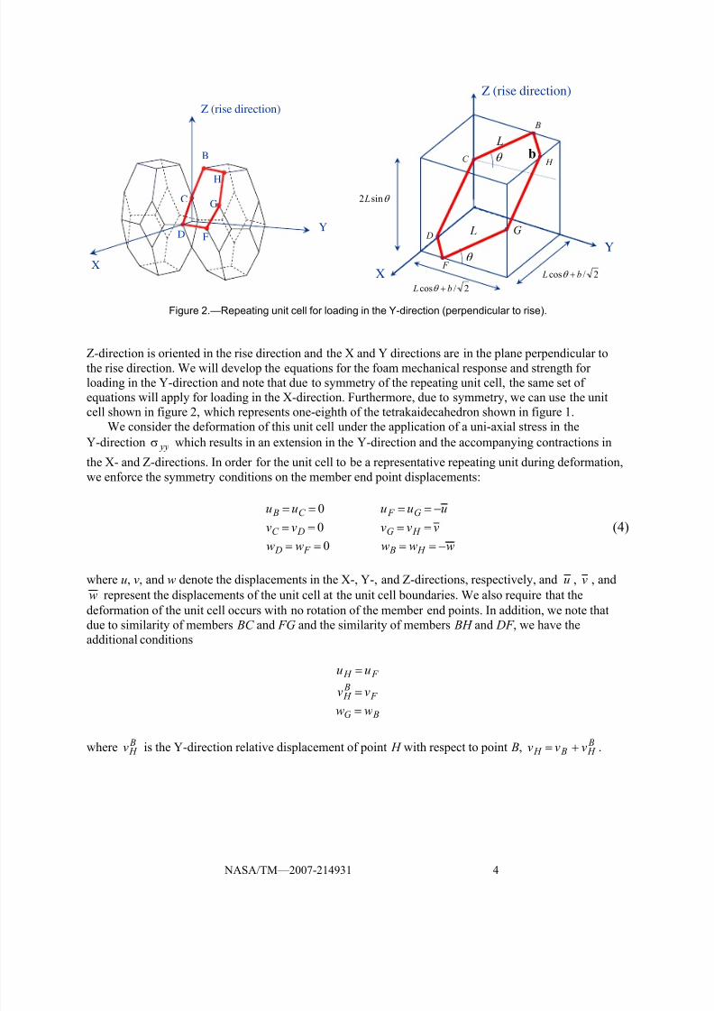
Figure 2.—Repeating unit cell for loading in the Y-direction (perpendicular to rise).
Z-direction is oriented in the rise direction and the X and Y directions are in the plane perpendicular tothe rise direction. We will develop the equations for the foam mechanical response and strength for
loading in the Y-direction and note that due to symmetry of the repeating unit cell, the same set of
equations will apply for loading in the X-direction. Furthermore, due to symmetry, we can use the unit
cell shown in figure 2, which represents one-eighth of the tetrakaidecahedron shown in figure 1.
We consider the deformation of this unit cell under the application of a uni-axial stress in the
Y-direction yyσ which results in an extension in the Y-direction and the accompanying contractions in
the X- and Z-directions. In order for the unit cell to be a representative repeating unit during deformation,
we enforce the symmetry conditions on the member end point displacements:
0uu C B == uuu G F −==
0vv DC == vvv H G == (4)0ww F D == www H B −==
where u, v, and w denote the displacements in the X-, Y-, and Z-directions, respectively, and u , v , and
w represent the displacements of the unit cell at the unit cell boundaries. We also require that the
deformation of the unit cell occurs with no rotation of the member end points. In addition, we note that
due to similarity of members BC and FG and the similarity of members BH and DF , we have the
additional conditions
F H uu =
F B H vv =
BG ww =
where B H v is the Y-direction relative displacement of point H with respect to point B, B
H B H vvv += .
Y
Z (rise direction)
2/cos b L +θ
θ sin2 L
H
G
F
D
C
X
θ
θ
L
L
2/cos b L +θ
b

8/3/2019 Roy M. Sullivan, Louis J. Ghosn and Bradley A. Lerch- An Elongated Tetrakaidecahedron Model for Open-Celled Foams
http://slidepdf.com/reader/full/roy-m-sullivan-louis-j-ghosn-and-bradley-a-lerch-an-elongated-tetrakaidecahedron 9/32
NASA/TM—2007-214931 5
Z
Y
θ
2/cos b L +θ
θ sin2 L
F
G
H B
C
2/b
L
v
w
w
D
(a) Y-Z plane (b) X-Y plane
Figure 3.—Unit cell deformation for loading in the Y-direction.
The deformation of the unit cell is illustrated in figure 3. It is straightforward to write the strains in
terms of the unit cell boundary displacements
b L
u xx
2cos2
2
+θ
−=ε
b L
v yy
2cos2
2
+θ=ε (5)
θ−
=εsin2 L
w zz
Due to the loading on the unit cell and the restrictions on the displacements, the members CD and GH carry no axial load or bending moment and therefore they do not contribute to the strain energy.
Furthermore, since the members BC and FG have the same length, orientation and stiffness and since the
same is true for members BH and DF , the strain energy of the assemblage of members BC and BH are
exactly equal to the strain energy of the assemblage of members DF and FG. Thus, the total strain energy
of the deformation of the unit cell is
( ) BH BC U U U += 2 (6)
and we need only consider further the deformation of members BC and BH .
Now since vv H = , we also have that 1v
v
v
v B H B =
⎟⎟
⎠
⎞
⎜⎜
⎝
⎛ +⎟
⎠
⎞⎜⎝
⎛ . Furthermore, it can be shown that, due to
the relative stiffness of members BC and BH , the fractional displacements are
)( ) ( )3232
222
sin2cos212
sincos122
b L A b L I
AL I L
v
v B
+θ++θ
θ+θ=
(7)
( )( ) ( )3232
2
sin2cos212
12
b L A b L I
Ab I b
v
v B H
+θ++θ
+=
X
Y
B
D
H
2/cos b L +θ
2/cos b L +θ
G
F
C
v
uu

8/3/2019 Roy M. Sullivan, Louis J. Ghosn and Bradley A. Lerch- An Elongated Tetrakaidecahedron Model for Open-Celled Foams
http://slidepdf.com/reader/full/roy-m-sullivan-louis-j-ghosn-and-bradley-a-lerch-an-elongated-tetrakaidecahedron 10/32
NASA/TM—2007-214931 6
The strain energy for a single structural member carrying an axial force and bending moment is
(Laible (1985))
ds sM EI
AE
L N U
L)(
2
1
2 0
22
∫ += (8)
where N is the axial force and M ( s) is the equation for the bending moment written as a function of the
local length coordinate s, where s is oriented along the member length. We note that all members in the
one-eighth unit cell have a cross-sectional area of A/2, since they are on the boundary of the unit cell and
are shared by two adjacent unit cells. Likewise, the moment of inertia of members BC and BH is I /2,
since, given the deformation of the unit cell specified by equation (4) and illustrated in figure 3, the axis
of bending is perpendicular to the boundary surface for both members. Thus, the axial force and bending
moment in members BC and BH may be written in terms of the member end point displacements as
( )θ+θ= sincos2
B B BC wv L
EA N
( ) B H H BH vu
b
EA N +=22
(9)
( )θ+θ−⎟⎟ ⎠
⎞⎜⎜⎝
⎛ −= cossin
63)(
32 B B BC wv s L
EI
L
EI sM
( ) B H H BH vu s
b
EI
b
EI sM +−⎟
⎟ ⎠
⎞⎜⎜⎝
⎛ −=
32
23
2
23)(
Setting uu H −= and ww B −= and making the substitutions vv
v v B B ⎟ ⎠ ⎞⎜⎝ ⎛ = and vv
v v
B
H B H ⎟⎟ ⎠
⎞
⎜⎜⎝
⎛ = in
equation (9), the strain energy in members BC and BH are written in terms of the unit cell boundary
displacements using equation (8) as
2
3
2
cossin3
sincos4
⎥⎦
⎤⎢⎣
⎡θ−θ⎟
⎠
⎞⎜⎝
⎛ −+⎥
⎦
⎤⎢⎣
⎡θ−θ⎟
⎠
⎞⎜⎝
⎛ = wv
v
v
L
EI wv
v
v
L
EA U B B
BC
(10)2
3
2
2
3
8⎥⎥
⎦
⎤
⎢⎢
⎣
⎡
⎟⎟
⎠
⎞
⎜⎜
⎝
⎛ ++
⎥⎥
⎦
⎤
⎢⎢
⎣
⎡
⎟⎟
⎠
⎞
⎜⎜
⎝
⎛ +−= v
v
v u
b
EI v
v
v u
b
EA U
B H
B H
BH
The work applied to the unit cell by the application of the applied stress yyσ acting over the
displacement v is
( ) vb
L LW yy ⎥
⎦
⎤⎢⎣
⎡⎟ ⎠
⎞⎜⎝
⎛ +=
2cossin2 θ θ σ (11)

8/3/2019 Roy M. Sullivan, Louis J. Ghosn and Bradley A. Lerch- An Elongated Tetrakaidecahedron Model for Open-Celled Foams
http://slidepdf.com/reader/full/roy-m-sullivan-louis-j-ghosn-and-bradley-a-lerch-an-elongated-tetrakaidecahedron 11/32
NASA/TM—2007-214931 7
The product of the terms in square brackets in equation (11) represents the total force applied to the unit
cell in the Y-direction, a force which is statically equivalent to the applied stress yyσ acting over the area
⎟⎟ ⎠
⎞⎜⎜⎝
⎛ +θθ
2cos)sin2(
b L L .
Following Zhu, et al. (1997), we next apply the Theorem of Minimum Potential Energy (Love, 1944),
which is
0u
U =
∂
∂0
v
U =
∂
∂0
w
U =
∂
∂
Direct substitution of the expression for U from equations (6) and (10), however, leads to a trivial result.
Since U W 2= and therefore U W U −= , we can write a mixed and more useful form of U which
includes the applied stress and the unit cell boundary displacements. A more convenient form of the
Minimum Potential Energy Theorem is then
( )0
u
U W =
∂
−∂
( )0
v
U W =
∂
−∂
( )0
w
U W =
∂
−∂(12)
Substituting equation (10) into equation (6) and substituting the result along with equation (11) into
equation (12) leads to the following set of three simultaneous equations written in terms of the boundary
displacements
01212
33 v
v
v
b
EA
b
EI u
b
EA
b
EI B H =
⎟⎟
⎠
⎞
⎜⎜
⎝
⎛ ⎟⎟ ⎠
⎞⎜⎜⎝
⎛ −+⎟⎟
⎠
⎞⎜⎜⎝
⎛ +
(13a)
u
v
v
b
EA
b
EI B H
⎟⎟
⎠
⎞
⎜⎜
⎝
⎛
⎟⎟
⎠
⎞
⎜⎜
⎝
⎛ −
3
12v
v
v
b
EA
b
EI
v
v
L
EI
L
EA B H B
⎥⎥⎥
⎦
⎤
⎢⎢⎢
⎣
⎡
⎟⎟
⎠
⎞
⎜⎜
⎝
⎛ ⎟⎟ ⎠
⎞⎜⎜⎝
⎛ ++⎟
⎠
⎞⎜⎝
⎛ ⎟⎟ ⎠
⎞⎜⎜⎝
⎛ θ+θ+
2
3
22
3
2 12sin
24cos
2
(13b)
( )b L Lw
v
v
L
EI
L
EA yy
B 2cos2sin2sincos242
3+θθσ=
⎥⎥
⎦
⎤
⎢⎢
⎣
⎡θθ
⎟⎟
⎠
⎞
⎜⎜
⎝
⎛
⎟⎟
⎠
⎞
⎜⎜
⎝
⎛ −−
0sincos12
sincos12 22
33 =⎟⎟ ⎠
⎞
⎜⎜⎝
⎛
θ+θ+⎥⎦
⎤
⎢⎣
⎡
θθ⎟ ⎠
⎞⎜⎝
⎛ ⎟⎟ ⎠
⎞
⎜⎜⎝
⎛
−− w L
EA
L
EI vv
v
L
EI
L
EA B
(13c)

8/3/2019 Roy M. Sullivan, Louis J. Ghosn and Bradley A. Lerch- An Elongated Tetrakaidecahedron Model for Open-Celled Foams
http://slidepdf.com/reader/full/roy-m-sullivan-louis-j-ghosn-and-bradley-a-lerch-an-elongated-tetrakaidecahedron 12/32
NASA/TM—2007-214931 8
Using equation (7), the solution to equation (13) yields
( ) ( )⎪⎭
⎪⎬⎫
⎪⎩
⎪⎨⎧
−+θθσ−= EI
b
AE
bb L Lu yy
2422cos2sin
3
(14a)
( ) ( )⎪⎭
⎪⎬⎫
⎪⎩
⎪⎨⎧ +θ
++θ
+θθσ= EI
b L
AE
b Lb L Lv yy
24
sin2
2
cos22cos2sin
3232
(14b)
( ) ( ) θθ⎪⎭
⎪⎬⎫
⎪⎩
⎪⎨⎧
−+θθσ−= sincos12
2cos2sin3
EI
L
AE
Lb L Lw yy (14c)
Since the Young’s modulus in the Y-direction is yy
yy y E
ε
σ= , substituting the expression for v from
equation (14b) into the expression for yyε from equation (5) yields
( )⎥⎦⎤
⎢⎣
⎡ +θ++θθ=
b L A
I b L L
EI E y
2323cos2
12sin2sin
12(15)
Furthermore, we have for the Poisson’s ratios
v
u
yy
xx yx =
ε
ε−=υ
and (16)
(θ
+θ=
ε
ε−=υ
sin4
2cos2
Lv
b Lw
yy
zz yz
which upon substitution of the expressions for v and w become
( )( ) ( )3232
2
sin2cos212
12
b L Ab L I
I Abb yx
+θ++θ
−=υ
and (17)
( )( )( ) ( )[ ]3232
2
sin2cos2122
cos2cos212
b L Ab L I
b L I AL yz
+θ++θ
θ+θ−=υ .

8/3/2019 Roy M. Sullivan, Louis J. Ghosn and Bradley A. Lerch- An Elongated Tetrakaidecahedron Model for Open-Celled Foams
http://slidepdf.com/reader/full/roy-m-sullivan-louis-j-ghosn-and-bradley-a-lerch-an-elongated-tetrakaidecahedron 13/32
NASA/TM—2007-214931 9
The axial force and maximum moment in the members of length L (members BC and FG) are
obtained by substituting the expressions for Bv and Bw into the expressions for BC N and BC M in
equation (9). The maximum moment occurs at the member ends, at either s = 0 or s = L. Recalling that
ww B =− , the expression for Bv and Bw are obtained from the first expression in equation (7) and from
equation (14). Substituting these into equation (9) yields
( ) ( )b L LM M yy
FG BC 2cos2sin2
2 +θθσ
==
(18)
( θθ+θσ== sincos2cos2 Lb L N N yy FG BC
The maximum stress in any member isS
M
A
N +=σmax , where S is the foam edge section modulus.
Substituting equation (18) leads to
[ ]b LS
L
A
L L x
yy
2cos22
sinsincos 22
max
+θ⎥⎥⎦
⎤
⎢⎢⎣
⎡ θ+
θθ
σ
=σ (19)
where L xS is the section modulus for the members of length L bending about the section neutral axis
which is parallel to the unit cell X-direction.
We assume that foam failure occurs when the foam stresses produce a maximum stress in any of the
edges which is equal to the ultimate strength of the solid material, that is when ult σ=σmax . We will
assume that this criterion holds true whether the maximum stress is tensile or compressive. Therefore, the
ultimate strength of the foam in the Y-direction, based on failure of the edges of length L, is given as
[ ]b LS
L
A
L L x
ult ult yy
2cos22
sinsincos22
+θ⎥⎥⎦
⎤
⎢⎢⎣
⎡ θ+
θθ
σ=σ (20)
The maximum moment and axial force in the members BH and DF is
( )b L LbM M yy
DF BH 2cos2sin22
+θθσ
==
(21)
( )b L L N N yy DF BH 2cos2sin2
+θθσ
==
This leads to

8/3/2019 Roy M. Sullivan, Louis J. Ghosn and Bradley A. Lerch- An Elongated Tetrakaidecahedron Model for Open-Celled Foams
http://slidepdf.com/reader/full/roy-m-sullivan-louis-j-ghosn-and-bradley-a-lerch-an-elongated-tetrakaidecahedron 14/32
NASA/TM—2007-214931 10
[ ]b LS
Lb
A
Lb
z
yy
2cos222
sin
2
sin
max
+θ⎥⎥⎦
⎤
⎢⎢⎣
⎡ θ+
θ
σ=σ (22)
where
b
z S is the section modulus for members of length b bending about the section neutral axis which is parallel to the unit cell Z-direction. The ultimate foam strength, based on failure of these members of
length b, is therefore
[ ]b LS
Lb
A
Lb
z
ult ult yy
2cos222
sin
2
sin+θ
⎥⎥⎦
⎤
⎢⎢⎣
⎡ θ+
θ
σ=σ (23)
In low density foams, bending stresses tend to be much more significant in contributing to material
failure than the axial force contributions (Huber and Gibson (1988) and Ridha, et al. (2006)). Ignoring the
axial terms in equations (20) and (23), the denominator in equation (20) will always be larger than the
denominator in equation (23) as long as the unit cell is elongated such that LS
bS
b z
L x>θsin2 . As a result,
the edges with length L will fail at a lower applied stress yyσ than the edges with length b and hence
equation (20) will always yield a lower estimate of the ultimate strength than equation (23).
2.4 Loading in the Z-direction (Rise)
We now seek to develop an analogous set of equations for loading in the Z (rise) direction. For
loading in the Z-direction, it is more convenient to use the repeating unit shown in figure 4. Since the
members AC , BC , DC , and CE lie within the boundaries of the unit cell, and are not shared by an adjacent
unit cell, it will be assumed that they have area A and moment of inertia I .
A
C
B
D
E
X
Y
Z (rise direction)
Figure 4.—Repeating unit cell for loading in the Z-direction (rise direction).
X
Y
Z (rise direction)
C
BA
θ sin2 L
L
b L +θ cos2
b L +θ cos2
θ
2/bD
E

8/3/2019 Roy M. Sullivan, Louis J. Ghosn and Bradley A. Lerch- An Elongated Tetrakaidecahedron Model for Open-Celled Foams
http://slidepdf.com/reader/full/roy-m-sullivan-louis-j-ghosn-and-bradley-a-lerch-an-elongated-tetrakaidecahedron 15/32

8/3/2019 Roy M. Sullivan, Louis J. Ghosn and Bradley A. Lerch- An Elongated Tetrakaidecahedron Model for Open-Celled Foams
http://slidepdf.com/reader/full/roy-m-sullivan-louis-j-ghosn-and-bradley-a-lerch-an-elongated-tetrakaidecahedron 16/32
NASA/TM—2007-214931 12
Making the substitutions vv B −= and ww B = in equation (26) and using equation (8), the strain energy
of deformation is obtained as
( ) ( )2
3
2cossin
24sincos
24 θ+θ+θ+θ−== wv
L
EI wv
L
EAU U BC (27)
The work performed by the applied stress zz σ acting over the displacement w on the top face and over
the displacement w− on the bottom face is
( ) wb LW zz
2cos22 +θσ= (28)
Applying the Minimum Potential Energy Theorem yields the set of equations
0sincos12
sin12
cos2
2
2
2 =θθ⎟⎟ ⎠
⎞⎜⎜⎝
⎛ −−⎟⎟
⎠
⎞⎜⎜⎝
⎛ θ+θ w
L
I Av
L
I A (29a)
w L
EA
L
EI v
L
EI
L
EA⎟⎟ ⎠
⎞⎜⎜⎝
⎛ θ+θ+θθ⎟⎟
⎠
⎞⎜⎜⎝
⎛ −− 22
33sin
2cos
24sincos
242 ( )2cos2 b L zz +θσ= (29b)
the solution to which yields
( ) θθ⎪⎭
⎪⎬⎫
⎪⎩
⎪⎨⎧
−+θσ−= sincos242
cos23
2
EI
L
AE
Lb Lv zz (30a)
( ) ⎪⎭⎪⎬⎫
⎪⎩⎪⎨⎧ θ+θ+θσ=
EI L
AE Lb Lw zz
24cos
2sincos2
2322 (30b)
The Young’s modulus ⎟⎟ ⎠
⎞⎜⎜⎝
⎛
ε
σ=
zz
zz z E is obtained by substituting the expression for w from
equation (30b) into equation (25), which results in
[ ]2
2
222 cos2
sin12cos
sin24
b L
AL
I L
EI E z
+θ⎥⎥⎦
⎤
⎢⎢⎣
⎡ θ+θ
θ= (31)
Since yy xx ε=ε , then zy zx υ=υ . Using zz
yy zy zx ε
ε−=υ=υ , we get
( )b Lw
Lv
zz
yy zy zx
2cos2
sin2
+θ
θ=
ε
ε−=υ=υ (32)

8/3/2019 Roy M. Sullivan, Louis J. Ghosn and Bradley A. Lerch- An Elongated Tetrakaidecahedron Model for Open-Celled Foams
http://slidepdf.com/reader/full/roy-m-sullivan-louis-j-ghosn-and-bradley-a-lerch-an-elongated-tetrakaidecahedron 17/32
NASA/TM—2007-214931 13
and upon substituting the expressions for the displacements from equation (30), equation (32) becomes
)[ ][ ]b L AL IL
I AL L zy zx
+θθ+θ
θθ−=υ=υ
cos2cossin12
sincos122
232
222
(33)
Substituting the expressions from equation (30) into equation (26) yields for the axial force and
maximum bending moment
( )2cos22
sinb L N zz
BC +θθσ
=
(34)
( )2cos24
cosb L
LM zz
BC +θθσ
=
SinceS
M
A
N +=σ
max, we obtain
[ ]2
max
cos24
cos
2
sinb L
S
L
A L x
zz
+θ⎥⎥⎦
⎤
⎢⎢⎣
⎡ θ+
θ
σ=σ (35)
and therefore the ultimate strength of the foam in the Z-direction is given as
[ ]2
cos24
cos
2
sin
b LS
L
A L x
ult ult zz
+θ⎥⎥⎦
⎤
⎢⎢⎣
⎡ θ
+
θ
σ=σ (36)
2.5 Stiffness and Strength Ratios
Defining the stiffness ratio as y
z E
E
E R = , then equations (1), (2), (15), and (31) lead to
⎥⎦⎤⎢
⎣⎡ θ+θ
⎥⎥⎦
⎤
⎢⎢⎣
⎡⎟ ⎠
⎞⎜⎝
⎛ +θ+⎟ ⎠
⎞⎜⎝
⎛ +θ
=
22
2
2
2
32
2
sin12cos
cos212
sin2
4 AL
I
L
b
AL
I
L
b
R R E (37)
Defining the strength ratio asult yy
ult zz R
σ
σ=σ and assuming that foam failure in the Y-direction occurs
due to failure of the members of length L, then equations (1), (2), (19), and (35) lead to

8/3/2019 Roy M. Sullivan, Louis J. Ghosn and Bradley A. Lerch- An Elongated Tetrakaidecahedron Model for Open-Celled Foams
http://slidepdf.com/reader/full/roy-m-sullivan-louis-j-ghosn-and-bradley-a-lerch-an-elongated-tetrakaidecahedron 18/32
NASA/TM—2007-214931 14
θ+θ
θ+θ=σ
cossin2
sincos2
ALS
ALS R R
L x
L x (38)
2.6 Isotropic Foams
In the special case of isotropic foams with an equi-axed repeating unit, we have the conditions H = D and E y = E z , or in terms of the aspect and stiffness ratios, R = R E = 1. Using equation (37), it is easily
shown that these two conditions are only satisfied when b = L and4
π=θ . Setting b = L and
4
π=θ , both
equations (15) and (31) reduce to
*
2
4 121
26 E
AL
I L
EI E E z y =
⎥⎦
⎤⎢⎣
⎡+
== (39)
which is the expression obtained by Zhu, et al. (1997) for isotropic, open-celled foams. Also, the
expressions for the Poisson’s ratios, equations (17) and (33), all reduce to
( )( ) I AL
I AL
12
125.0
2
2*
+
−=υ
the expression for the Poisson’s ratio obtained by Zhu, et al. (1997) for the isotropic case. Furthermore,
the relative density becomes2
22
3
L
A=γ .
3. Application to Experimental Studies
3.1 Relative Modulus Versus Relative Density in Isotropic Foams
We first apply the equations derived in the previous section to simulate the variation of the relative
modulus E
E *with the relative density γ for isotropic foams. For isotropic foams, the relative modulus
follows from equation (39). Assuming that the edge cross-sections are circular with radius r , the relative
modulus is
2
4
*
314
26
⎟ ⎠
⎞⎜⎝
⎛ +
⎟
⎠
⎞⎜
⎝
⎛ π
=
L
r
L
r
E
E (40)
8/3/2019 Roy M. Sullivan, Louis J. Ghosn and Bradley A. Lerch- An Elongated Tetrakaidecahedron Model for Open-Celled Foams
http://slidepdf.com/reader/full/roy-m-sullivan-louis-j-ghosn-and-bradley-a-lerch-an-elongated-tetrakaidecahedron 19/32
NASA/TM—2007-214931 15
and the relative density is
22
3
2
⎟ ⎠
⎞⎜⎝
⎛ π=γ
L
r
(41)
Solving equation (41) for the ratio L
r and substituting the result into equation (40) leads to
γ+π
γ=
223
24 2*
E
E (42)
By comparison, the relative modulus for a square cross-section is( )γ+
γ
2233
24 2
, which is similar to
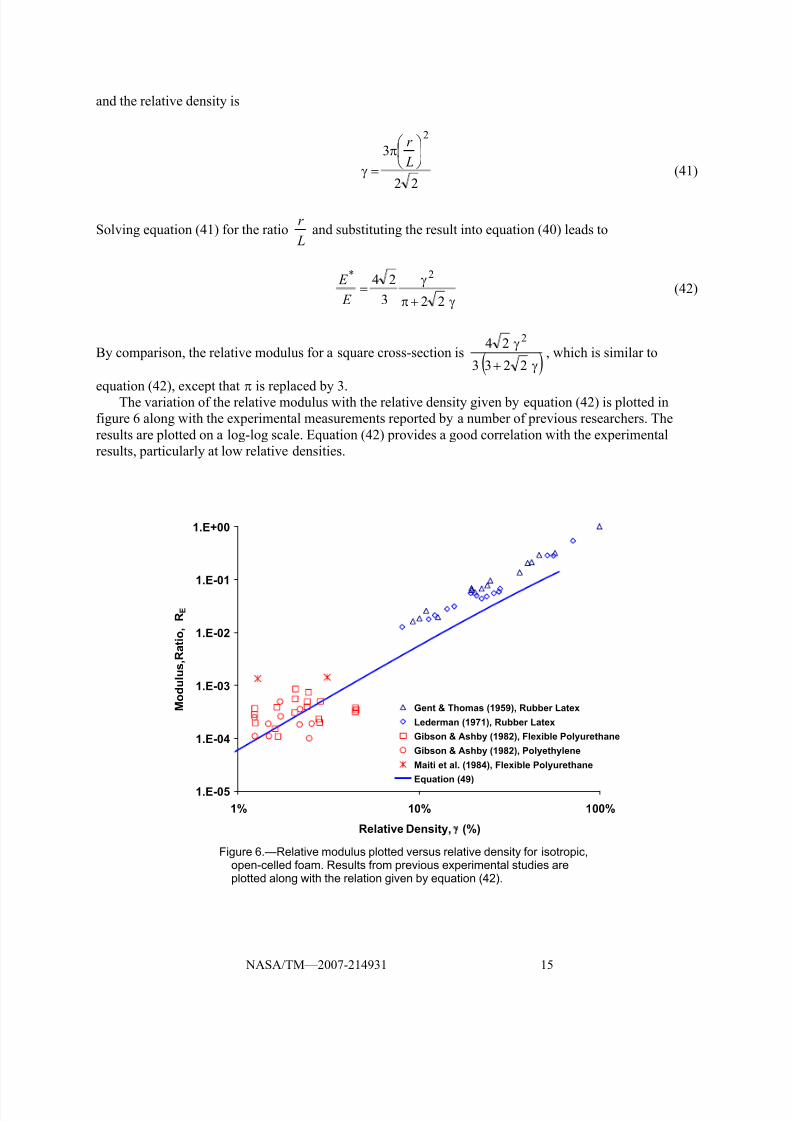
equation (42), except that π is replaced by 3.The variation of the relative modulus with the relative density given by equation (42) is plotted in
figure 6 along with the experimental measurements reported by a number of previous researchers. The
results are plotted on a log-log scale. Equation (42) provides a good correlation with the experimental
results, particularly at low relative densities.
1.E-05
1.E-04
1.E-03
1.E-02
1.E-01
1.E+00
1% 10% 100%
Relative Density, γ (%)
M o d u l u s , R a t i o ,
R E
Gent & Thomas (1959), Rubber Latex
Lederman (1971), Rubber Latex
Gibson & Ashby (1982), Flexible Polyurethane
Gibson & Ashby (1982), Polyethylene
Maiti et al. (1984), Flexible Polyurethane
Equation (49)
Figure 6.—Relative modulus plotted versus relative density for isotropic,open-celled foam. Results from previous experimental studies areplotted along with the relation given by equation (42).
8/3/2019 Roy M. Sullivan, Louis J. Ghosn and Bradley A. Lerch- An Elongated Tetrakaidecahedron Model for Open-Celled Foams
http://slidepdf.com/reader/full/roy-m-sullivan-louis-j-ghosn-and-bradley-a-lerch-an-elongated-tetrakaidecahedron 20/32
NASA/TM—2007-214931 16
3.2 Stiffness and Strength Ratio Versus Cell Aspect Ratio and Relative Density for
Non-isotropic Foams With a Restricted Unit Cell Geometry
The stiffness ratio and its dependence on the cell aspect ratio has been measured and reported by
previous researchers for several non-isotropic polymer foams and the variation of the strength ratio with
cell aspect ratio for Porolon was measured by Polyakov and Tarakanov (1967). In this section, we seek to
rewrite the equations derived in section 2 for the ratios R E and Rσ, and obtain expressions for these ratiosin terms of the two variables R and γ, so that we may compare the model predictions with the
measurements made by previous researchers.
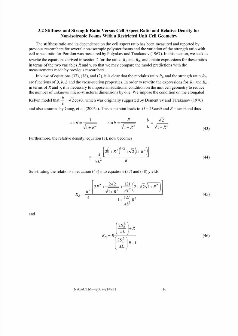
In view of equations (37), (38), and (2), it is clear that the modulus ratio R E and the strength ratio Rσ
are functions of θ, b, L and the cross-section properties. In order to rewrite the expressions for R E and Rσ
in terms of R and γ, it is necessary to impose an additional condition on the unit cell geometry to reduce
the number of unknown micro-structural dimensions by one. We impose the condition on the elongated
Kelvin model that θ= cos2 L
b, which was originally suggested by Dement’ev and Tarakanov (1970)
and also assumed by Gong, et al. (2005a). This constraint leads to D = 4 Lcosθ and R = tan θ and thus
21
1cos
R+=θ
21
sin R
R
+=θ
2
1
2
R L
b
+=
(43)
Furthermore, the relative density, equation (3), now becomes
( ) ( ) R
R R
L
A ⎥⎦⎤
⎢⎣⎡ +++
=γ
22/32
2
1212
8(44)
Substituting the relations in equation (43) into equations (37) and (38) yields
2
2
2
22
2
2
121
12212
1
222
4 R
AL
I
R AL
I
R
R R
R E
+
⎥⎥⎦
⎤
⎢⎢⎣
⎡⎟ ⎠ ⎞
⎜⎝ ⎛ +++
++
= (45)
and
12
2
+⎟⎟
⎠
⎞
⎜⎜
⎝
⎛
+⎟⎟
⎠
⎞
⎜⎜
⎝
⎛
=σ
R AL
S
R AL
S
R R L x
L x
(46)

8/3/2019 Roy M. Sullivan, Louis J. Ghosn and Bradley A. Lerch- An Elongated Tetrakaidecahedron Model for Open-Celled Foams
http://slidepdf.com/reader/full/roy-m-sullivan-louis-j-ghosn-and-bradley-a-lerch-an-elongated-tetrakaidecahedron 21/32
NASA/TM—2007-214931 17
If we again assume that the edge cross-section is circular with a radius r , then
2
23
12⎟ ⎠
⎞⎜⎝
⎛ = L
r
L A
I and
L
r
L A
S L x
2
2= , and equation (44) may be rearranged to obtain
( ) ( )22/32
2
21212
243
12
R R
R
L
r
AL
I
+π++π
γ=⎟
⎠
⎞⎜⎝
⎛ =
and (47)
( ) ( )22/32 1212
2
2
2
R R
R
L
r
AL
S L x
+π++π
γ==
Substituting the relations in equation (47) into equations (45) and (46) leads to
( )
( )
( )⎥⎥⎥⎥
⎦
⎤
⎢⎢⎢⎢
⎣
⎡
γ⎟ ⎠ ⎞
⎜⎝ ⎛ +++
+π
⎥⎥⎥⎥
⎦
⎤
⎢⎢⎢⎢
⎣
⎡
γ⎟ ⎠ ⎞
⎜⎝ ⎛ +++
⎟ ⎠ ⎞
⎜⎝ ⎛ ++
+π⎟⎟
⎠
⎞
⎜⎜
⎝
⎛
++
=
22
3
22
2
2
2
2
1221
242
1221
12212
1
2
R R
R
R R
R R
R
R
R R E (48)
and
( ) ( )( ) ( )22/32
22/32
12122
12122
R R R R
R R R R R R
+π++π+γ
+π++π+γ=σ (49)
We note, once again, that an expression similar to equation (48) is obtained if a square cross-section
is assumed, except, in that case, π in the numerator and denominator is replaced by a 3.
Equations (48) and (49) are analogous to equation (1) and (4) in Huber and Gibson (1988). Although
considerably more cumbersome, equations (48) and (49) are more inclusive than Huber and Gibson’s
relations, as they account for both axial and bending deformations of the cell edges and they include the
effect of the relative density on the stiffness and strength ratios.Using equation (48), the modulus ratio is plotted versus cell aspect ratio and relative density in
figure 7. The experimental results reported by a number of previous researchers are also included. Note
that the stiffness ratio is a weak function of the relative density, particularly as the cell aspect ratio
approaches unity. As the cell aspect ratio approaches unity, all the curves must collapse to the same point,
that is, at R = 1 and R E = 1.
The variation of the strength ratio with the cell aspect ratio, given by equation (49), is plotted in
figure 8. The variation of the strength ratio with the cell aspect ratio for Porolon as reported by
Dement’ev and Tarakanov (1970) (originally reported by Polyakov and Tarakanov (1967)) is also plotted

8/3/2019 Roy M. Sullivan, Louis J. Ghosn and Bradley A. Lerch- An Elongated Tetrakaidecahedron Model for Open-Celled Foams
http://slidepdf.com/reader/full/roy-m-sullivan-louis-j-ghosn-and-bradley-a-lerch-an-elongated-tetrakaidecahedron 22/32
NASA/TM—2007-214931 18
1.0
1.5
2.0
2.5
3.0
3.5
4.0
4.5
5.0
1.00 1.10 1.20 1.30 1.40 1.50 1.60 1.70 1.80
Cell Aspect Ratio, R
M o d u l u s R a t i o ,
R E
Gupta & al. (1986), Polyisocyanurate
Hilyard (1982), Flexible Polyurethane
Huber & Gibson (1988), Flexible Polyurethane
Huber & Gibson (1988), Rigid Polyurethane
Mehta & Colombo (1976), Polystyrene
Gong & al. (2005a), Polyester-Urethane
γ = 1%
510
15
Figure 7.—Modulus ratio plotted versus cell aspect ratio and relative
density. Results from previous experimental studies are plottedalong with that given by equation (48).
1.0
1.2
1.4
1.6
1.8
2.0
2.2
2.4
1.0 1.1 1.2 1.3 1.4 1.5 1.6
Cell Aspect Ratio, R
S t r e n g t h R a t i o ,
R
Experiment Results on Porolon fromPolyakov & Tarakanov (1967)
Equation (49)
Figure 8.—Strength ratio plotted versus cell aspect ratio. Results on Porolon
from Polyakov and Tarakanov (1967) as reported by Dement’ev and
Tarakanov (1970) plotted along with equation (49) for γ = 3 percent.
in figure 8. A relative density of 0.03 was used to plot equation (49), as this was the relative densityreported in the experimental study. Clearly, equation (49) provides a reasonably-close match with the
measured results, given the small amount of the experimental data available.
3.3. Analysis of Polymer Foams Using a General Description of the Unit Cell Geometry
We now apply the equations derived in section 2 to simulate the strength behavior of the rigid
polyurethane foams reported by Huber and Gibson (1988). We will allow for the most general description
of the unit cell geometry, which requires us to specify three dimensions to describe the unit cell geometry

8/3/2019 Roy M. Sullivan, Louis J. Ghosn and Bradley A. Lerch- An Elongated Tetrakaidecahedron Model for Open-Celled Foams
http://slidepdf.com/reader/full/roy-m-sullivan-louis-j-ghosn-and-bradley-a-lerch-an-elongated-tetrakaidecahedron 23/32
NASA/TM—2007-214931 19
plus a description of the edge cross-section. We will assume a circular edge cross-section and therefore
we need only to define the cross-section radius. Using the values for the cell width, the cell aspect ratio,
the relative density and the modulus ratio reported in Huber and Gibson (1988), we use the equations
derived in section 2 to calculate the unit cell dimensions and the edge cross-section radius for each of the
five rigid polyurethane foams. Using these four dimensions, the strength ratio for each of the five foams
can be calculated using a modified form of equation (38).
Now since the rigid polyurethane foams studied in Huber and Gibson (1988) were closed-cell foams,their microstructure includes cell faces which are stressed and deform with the application of the applied
stress. As such, the faces also contribute to the foam mechanical behavior. In addition, the edge cross-
sections are not really circular, but rather they resemble a three-cusp hypocycloid (Gong, et al. (2005a)).
As a result, the edge radii that are calculated for the foams are really an equivalent cross-section radius.
That is they represent the radius of a circular cross-section possessing a structural rigidity that is
equivalent to the combined structural rigidity of the cell faces and the three-cusp hypocycloid edges.
From equation (2), we have
R
R
L
b
2
cos2sin4 θ−θ= (50)
Using R
H D = and equation (1), equation (3) can be written as
θ
⎟ ⎠
⎞⎜⎝
⎛ +=γ
32
2
sin8
2
L
L
b AR
(51)
Assuming a circular edge cross-section with radius r and upon substituting equation (50), equation (51)
can be rewritten and rearranged as
( )θ−θ+πθγ=⎟
⎠ ⎞⎜
⎝ ⎛
cossin22
sin24 32
R R R Lr (52)
Also, assuming a circular edge cross-section allows us to replace2
12
AL
I with
2
3 ⎟ ⎠
⎞⎜⎝
⎛ L
r and rewrite
equation (37) as
[ ]3
22
22
2223sin12cos6 ⎟
⎠
⎞⎜⎝
⎛ +⎟ ⎠
⎞⎜⎝
⎛ ⎟ ⎠
⎞⎜⎝
⎛ +⎟ ⎠
⎞⎜⎝
⎛ θ−θ L
b R
L
r
L
b R
L
r R R E 0cos4sin2 222 =θ−θ+ E R R (53)
In order to solve for L, b, θ, and r , we could substitute equations (50) and (52) into equation (53) and,
using the identity relation θ−=θ 22 sin1cos , obtain an explicit algebraic equation in sin θ which can be
solved to obtain the value of θ. The resulting equation is, however, quite cumbersome. Instead, we choose
to solve the set of equations (50), (52), and (53) in an iterative manner, whereby these equations are
solved in series within each iteration.

8/3/2019 Roy M. Sullivan, Louis J. Ghosn and Bradley A. Lerch- An Elongated Tetrakaidecahedron Model for Open-Celled Foams
http://slidepdf.com/reader/full/roy-m-sullivan-louis-j-ghosn-and-bradley-a-lerch-an-elongated-tetrakaidecahedron 24/32
NASA/TM—2007-214931 20
The steps in the solution approach were to make an initial guess at the value of the inclination angle
θ, substitute this value into (50) and (52) and solve (50) and (52) for L
band
L
r , respectively. The values
of L
band
L
r were then substituted into equation (53) and equation (53) was solved for θ. This process
was repeated until the difference in the value of θ between two successive iterations was within anacceptable tolerance. The standard bisection method (Press, et al., 1992) was implemented to solve
equation (53) numerically for θ. The method converged usually within thirty iterations given an initial
bracketed guess for the inclination angle between 40 and 75°. Once the final value of θ is obtained from
the iterative solution, the value of L is determined fromθ
=sin4
RD L and the value of b and r is calculated
from equations (50) and (52), respectively.
The cell width, relative density, cell aspect ratio, modulus ratio and the measured compressive
strength ratio for each of the five rigid polyurethane foams reported in Huber and Gibson (1988) are listed
in table I. We have also listed the equivalent edge cross-section radius, the inclination angle and the
lengths of the edges L and b which were obtained from each iterative solution. Notice that the equivalent
cross-section radii seem to correlate with the measured relative densities, and the inclination angles seem
to correlate with the measure modulus ratios. Also, although the elongated tetrakaidecahedron shown infigure 1 is drawn so as to imply that the edges of length b are shorter than the edges of length L, this is not
strictly true. Indeed, one of the foams listed in table I has b = L and another has b > L.
TABLE I.—RESULTS FROM THE EXPERIMENTAL STUDY ON RIGID POLYURETHANE FOAMS BYHUBER AND GIBSON (1988) ALONG WITH THE RESULTS FROM THE NUMERICAL SOLUTION
Experimental data for rigid polyurethane foamsfrom Huber and Gibson (1988)
Solution results
Cell width,
D,mm
Relative
density,
γ
Cell aspect
ratio, R
Modulus
ratio,
R E
Exp. comp.
strengthratio,a
Rσ
Edge cross-
sectionalradius,
r ,
mm
Inclination
angle,
θ,deg
Edge
length, L,mm
Edge
length,b,
mm
Predicted
strength ratio,
Rσ
0.20 0.027 1.405 2.518 1.730 0.0070 53.91 0.087 0.069 1.880
0.20 0.053 1.470 3.312 1.943 0.0100 56.63 0.088 0.073 2.132
0.20 0.080 1.230 2.256 1.484 0.0117 53.29 0.077 0.077 1.582
0.20 0.107 1.275 1.475 1.152 0.0137 49.26 0.084 0.064 1.447
0.20 0.133 1.190 2.122 1.455 0.0149 52.98 0.075 0.078 1.498aExperimental compressive strength ratios were calculated from the plastic collapse stresses reported in Huber and
Gibson (1988).
Assuming a circular cross-section of radius r , equation (38) becomes
1tan2
tan2
+θ⎟ ⎠
⎞⎜⎝
⎛
θ+⎟ ⎠ ⎞⎜⎝ ⎛ =σ
L
r
Lr
R R (54)

8/3/2019 Roy M. Sullivan, Louis J. Ghosn and Bradley A. Lerch- An Elongated Tetrakaidecahedron Model for Open-Celled Foams
http://slidepdf.com/reader/full/roy-m-sullivan-louis-j-ghosn-and-bradley-a-lerch-an-elongated-tetrakaidecahedron 25/32
NASA/TM—2007-214931 21
0.0
0.5
1.0
1.5
2.0
2.5
2.7% 5.3% 8.0% 10.7% 13.3%
Relative Density, γ
S t r e n g t h R a t i o , R
σ
Experimental
Numerical Solution
Figure 9.—Comparison of the measured and predicted strength ratioplotted versus the foam relative density for rigid polyurethane foams.Experimental data from Huber and Gibson (1988).
The strength ratio was calculated for each foam using equation (54) and the values of r , θ, and L that were
obtained from the iterative solutions along with the measured values of R. The predicted strength ratios
are listed in table I; a comparison of the measured and predicted strength ratios is shown in figure 9. The
predicted strength ratios are within 10 percent of the measured strength ratios for all cases except for the
10.7 percent relative density foam where the error is close to 26 percent. It should be mentioned that the
value of the cell aspect ratio reported by Huber and Gibson (1988), for this foam, was brought into
question, as they reported difficulties with the microscope while measuring the micro-structure of this
foam. Further, the cell aspect ratio for this foam does not appear to be consistent with the measured
strength and stiffness ratios. The measured strength and stiffness ratios for the 10.7 percent relativedensity foam were the lowest of the five foams, whereas the cell aspect ratio was the median of the five
values. Ignoring the results for the 10.7 percent relative density foam, we can conclude that the equations
derived in section 2 as well as the iterative solution were successful in predicting the compressive strength
ratios for the closed-cell foams studied by Huber and Gibson (1988).
Finally, we note that, for all five cases, the value of the ratio L
bis not equal to the value of θcos2 ,
reinforcing our notion that the restriction on the unit cell geometry used by the previous researchers is
unfounded and adopted merely for the sake of convenience.
4. Concluding Remarks
The formulation by Zhu, et al. (1997) has been revised to include the mechanical and strength
behavior of non-isotropic foams. Equations for the foam Young’s modulus, Poisson’s ratio and strength
in the principal material directions were obtained by adopting an elongated Kelvin model as the repeating
unit cell. These equations were written in terms of the edge lengths and edge cross-section properties,
the inclination angle and the strength and stiffness of the solid material. The micro-mechanics model
is developed from the most general description of an elongated Kelvin model, as it requires three
independent dimensions to describe the unit cell geometry as well as a description of the edge
cross-section.

8/3/2019 Roy M. Sullivan, Louis J. Ghosn and Bradley A. Lerch- An Elongated Tetrakaidecahedron Model for Open-Celled Foams
http://slidepdf.com/reader/full/roy-m-sullivan-louis-j-ghosn-and-bradley-a-lerch-an-elongated-tetrakaidecahedron 26/32
NASA/TM—2007-214931 22
The model was applied to simulate the variation of the relative modulus with relative density in
isotropic foams as well as the variation of the modulus ratio and strength ratio with cell aspect ratio in
non-isotropic foams. In all cases, the model results were in good agreement with the experimental
measurements. The model was also applied to simulate the strength ratio in closed-cell rigid polyurethane
foams. Here, also, the model results were in good agreement with the measurements, as the predicted
strength ratio was within 10 percent of the measured strength ratios for all but one of the five foams.
In closing, it is worth noting that by adopting an elongated Kelvin model with the most generalgeometry, a more detailed description of the foam microstructure is required in order to apply the
resulting equations and predict the foam behavior. More specifically, it is now necessary to obtain four
separate physical and mechanical measurements of the foam in order to apply the equations. Aside from
this added burden, the model is an improvement over the previous models, since it is capable of more
closely representing the foam micro-structure for a wider range of foam materials. Thus, the resulting
equations should more accurately simulate the foam behavior for a wider range of foams.

8/3/2019 Roy M. Sullivan, Louis J. Ghosn and Bradley A. Lerch- An Elongated Tetrakaidecahedron Model for Open-Celled Foams
http://slidepdf.com/reader/full/roy-m-sullivan-louis-j-ghosn-and-bradley-a-lerch-an-elongated-tetrakaidecahedron 27/32
NASA/TM—2007-214931 23
Appendix
Relation Between the Minimum Allowable Inclination Angle and
the Length Ratio b/ L for an Elongated Tetrakaidecahedron
If the height H and width D of the tetrakaidecahedron are equal, the expression in equation (1) leads
to
L
b
2cossin2 =θ−θ (A1)
For an elongated tetrakaidecahedron ( H > D), we have the inequality
L
b
2cossin2 >θ−θ (A2)
Using the trigonometric identity, θ−=θ 2sin1cos , equation (A1) can be rearranged and rewritten as a
second-order polynomial in sin θ, that is,
012
sin22sin52
22 =⎟
⎟ ⎠
⎞⎜⎜⎝
⎛ −+θ−θ
L
b
L
b(A3)
The solution to equation (A3) is obtained using the quadratic formula resulting in the two solutions
2
2
1 1010
2
5
2sin
L
b
L
b−+=θ (A4a)
2
2
2 1010
2
5
2sin
L
b
L
b−−=θ (A4b)
where both roots are real provided 10≤ L
band where the two are identical when 10=
L
b. The
solutions listed in equation (A4) are plotted in figure A1.
It is easily shown that equation (A4a) is the solution to equation (A1) and that equation (A4b) is the
solution to
L
b
2
cossin2 +θ−=θ (A5)
Since equation (A5) has no physical significance here, we will ignore the latter of the two solutions in
equation (A4).

8/3/2019 Roy M. Sullivan, Louis J. Ghosn and Bradley A. Lerch- An Elongated Tetrakaidecahedron Model for Open-Celled Foams
http://slidepdf.com/reader/full/roy-m-sullivan-louis-j-ghosn-and-bradley-a-lerch-an-elongated-tetrakaidecahedron 28/32

8/3/2019 Roy M. Sullivan, Louis J. Ghosn and Bradley A. Lerch- An Elongated Tetrakaidecahedron Model for Open-Celled Foams
http://slidepdf.com/reader/full/roy-m-sullivan-louis-j-ghosn-and-bradley-a-lerch-an-elongated-tetrakaidecahedron 29/32
NASA/TM—2007-214931 25
References
Chajes, A., 1983. Structural Analysis, Prentice-Hall, Inc., Englewood Cliffs, NJ.
Dement’ev, A.G. and Tarakanov, O.G., 1970. Model analysis of the cellular structure of plastic foams
of the polyurethane type. Mekhanika Polimerov 5, 859–865. Translation Polymer Mechanics 6,
744–749.
Gent, A.N. and Thomas, A.G., 1959. The deformation of foamed elastic materials. Journal of AppliedPolymer Science I (1), 107–113.
Gibson, L.J. and Ashby, M.F., 1982. The mechanics of three-dimensional cellular materials. Proc. Roy.
Soc. A382 (1782), 43–59.
Gibson, L.J. and Ashby, M.F., 1997. Cellular Solids: Structure and Properties, Second Edition.
Cambridge University Press, Cambridge, UK.
Gong, L., Kyriakides, S., and Jang, W.Y., 2005a. Compressive response of open-celled foams, Part I:
Morphology and elastic properties. International Journal of Solids and Structures 42, 1355–1379.
Gong, L., Kyriakides, S. and Triantafyllidis, N., 2005b. On the stability of Kelvin cell foams under
compressive loads. Journal of the Mechanics and Physics of Solids 53, 771–794.
Gupta, S., Watson, B., Beaumont, P.W.R. and Ashby, M.F., 1986. Final Year Project, Cambridge
University Engineering Department, Cambridge, UK.
Hilyard, N.C. (ed.), 1982. Mechanics of Cellular Plastics. Applied Science, London.Huber, A.T. and Gibson, L.J., 1988. Anisotropy of foams. Journal of Materials Science 23, 3031–3040.
Laible, J.P., 1985. Structural Analysis. Holt Rinehart and Winston, New York.
Lederman, J.M., 1971. Journal of Applied Polymer Science 15, 693.
Love, A.E.H., 1944. A Treatise on the Mathematical Theory of Elasticity. Dover Publications, New York, NY.
Maiti, S.K., Gibson, L.J. and Ashby, M.F., 1984. Deformation and energy absorption diagrams for
cellular solids. Acta Metal. 32 (11), 1963–1975.
Mehta, B.S. and Colombo, E.A., 1976. Journal of Cellular Plastics 12, 59.
Polyakov, Y.N. and Tarakanov, O.G., 1967. in: Problems of the Physiochemical Mechanics of Fibrous
and Porous Disperse Structures and Materials (in Russian), Riga.
Press W.H., Teukolsky S.A., Vetterling W.T. and Flannery B.P., 1992. Numerical Recipes in FORTRAN:
The Art of Scientific Computing, Second Edition. Cambridge University Press, Cambridge, UK.
Ridha, M., Shim,V.P.W. and Yang, L.M., 2006. An elongated tetrakaidecahedral cell model for fracturein rigid polyurethane foam. Key Engineering Materials 306–308, 43–48.
Thomson, W. (Lord Kelvin), 1887. On the division of space with minimum partitional area. Phil. Mag.
24, 503–514.
Warren, W.E. and Kraynik, A.M., 1997. Linear elastic behavior of a low-density Kelvin foam with open
cells. Journal of Applied Mechanics 64, 787–794.
Zhu, H.X., Knott, J.F. and Mills, N.J., 1997. Analysis of the elastic properties of open-cell foams with
tetrakaidecahedral cells. Journal of the Mechanics and Physics of Solids 45 (3), 319–343.
8/3/2019 Roy M. Sullivan, Louis J. Ghosn and Bradley A. Lerch- An Elongated Tetrakaidecahedron Model for Open-Celled Foams
http://slidepdf.com/reader/full/roy-m-sullivan-louis-j-ghosn-and-bradley-a-lerch-an-elongated-tetrakaidecahedron 30/32

8/3/2019 Roy M. Sullivan, Louis J. Ghosn and Bradley A. Lerch- An Elongated Tetrakaidecahedron Model for Open-Celled Foams
http://slidepdf.com/reader/full/roy-m-sullivan-louis-j-ghosn-and-bradley-a-lerch-an-elongated-tetrakaidecahedron 31/32

8/3/2019 Roy M. Sullivan, Louis J. Ghosn and Bradley A. Lerch- An Elongated Tetrakaidecahedron Model for Open-Celled Foams
http://slidepdf.com/reader/full/roy-m-sullivan-louis-j-ghosn-and-bradley-a-lerch-an-elongated-tetrakaidecahedron 32/32