royal cyclone 1 extruder - plymouth industries inc. 1 extruder operator manual...royal cyclone 1...
TRANSCRIPT

ROYAL Cyclone 1 Extruder Operators’ Instruction Manual
P/N 161385 Rev 9/14
WARNING! THIS MACHINE IS DESIGNED FOR USE ON FLAT, LEVEL
ROOFS ONLY.
Keep this Manual with the Cyclone Extruder at all times.
It is the Cyclone Extruder owner’s responsibility to ensure that all of the
workers using this machine are thoroughly trained. Provide workers with
this Operator’s Manual. Make sure they understand its' contents. Read it
to them if necessary. Letting poorly trained workers use this machine can
result in property or machine damage and/or serious injury or death to
personnel.
Garlock provides this Operator’s Manual at the time of sale as a tool to
help instruct the owner/worker in the proper use of the Extruder.
ROYAL/Garlock expects the reseller and owner/worker to make every
effort to educate themselves in the safe and responsible use of this
Extruder before putting this machine into service.
Read and understand the
instructions in this Manual
before using this machine!
2
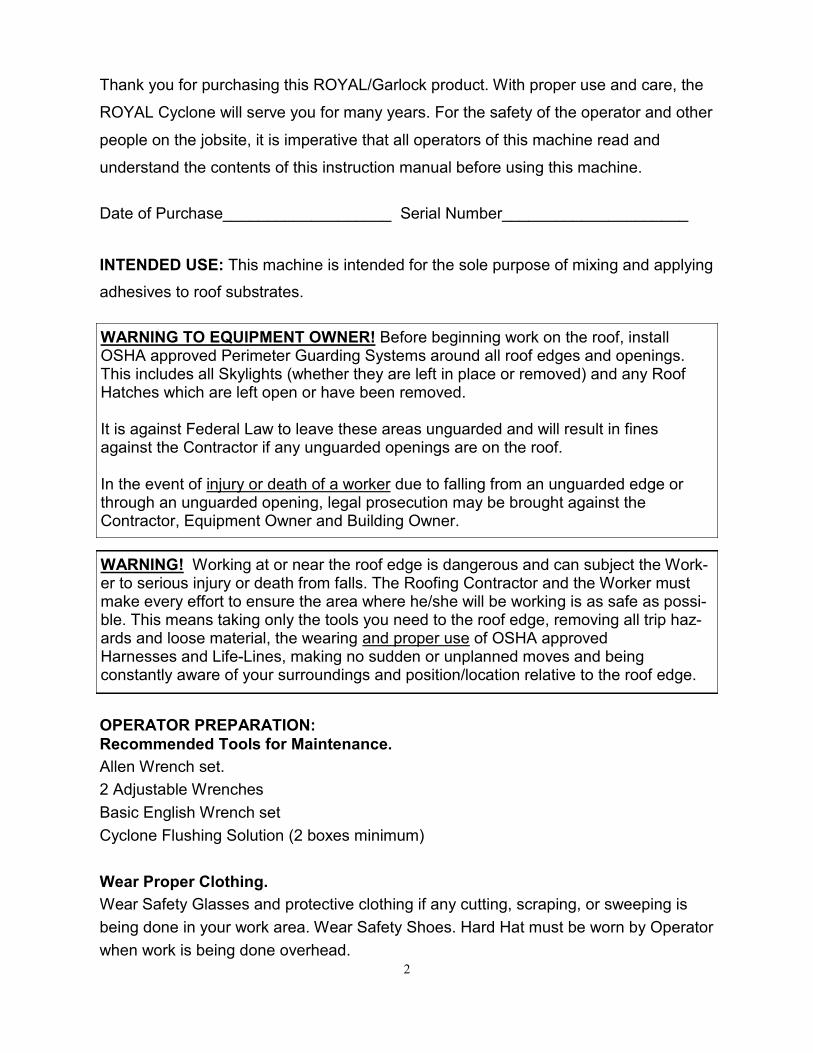
Thank you for purchasing this ROYAL/Garlock product. With proper use and care, the
ROYAL Cyclone will serve you for many years. For the safety of the operator and other
people on the jobsite, it is imperative that all operators of this machine read and
understand the contents of this instruction manual before using this machine.
Date of Purchase___________________ Serial Number_____________________
INTENDED USE: This machine is intended for the sole purpose of mixing and applying
adhesives to roof substrates.
WARNING TO EQUIPMENT OWNER! Before beginning work on the roof, install OSHA approved Perimeter Guarding Systems around all roof edges and openings. This includes all Skylights (whether they are left in place or removed) and any Roof Hatches which are left open or have been removed. It is against Federal Law to leave these areas unguarded and will result in fines against the Contractor if any unguarded openings are on the roof. In the event of injury or death of a worker due to falling from an unguarded edge or through an unguarded opening, legal prosecution may be brought against the Contractor, Equipment Owner and Building Owner.
WARNING! Working at or near the roof edge is dangerous and can subject the Work-er to serious injury or death from falls. The Roofing Contractor and the Worker must make every effort to ensure the area where he/she will be working is as safe as possi-ble. This means taking only the tools you need to the roof edge, removing all trip haz-ards and loose material, the wearing and proper use of OSHA approved Harnesses and Life-Lines, making no sudden or unplanned moves and being constantly aware of your surroundings and position/location relative to the roof edge.
OPERATOR PREPARATION:
Recommended Tools for Maintenance.
Allen Wrench set.
2 Adjustable Wrenches
Basic English Wrench set
Cyclone Flushing Solution (2 boxes minimum)
Wear Proper Clothing.
Wear Safety Glasses and protective clothing if any cutting, scraping, or sweeping is
being done in your work area. Wear Safety Shoes. Hard Hat must be worn by Operator
when work is being done overhead.

3
General Safety Information
The information in this manual must be understood and followed to insure safe,
productive operation of your Cyclone 1 Extruder.
As with all mechanical equipment, safety precautions must be taken when this equip-
ment is being used or serviced. Failure to follow the guidelines listed in this manual
and/or failure to use common sense may result in bodily injury and/or damage to
equipment and property.
PROTECTIVE EQUIPMENT:
Protective equipment such as safety glasses and protective gloves must be worn when
operating or servicing the Cyclone 1 Extruder. Follow guidelines and recommenda-
tions of material manufacturer. Consult your local OSHA office regarding respi-
rator requirements.
ACCEPTABLE USE:
The Cyclone 1 Extruder is designed for the dispensing of plural component urethane
foams and adhesive systems.
Under no circumstances should any acid or corrosive chemicals be used in this
machine.
Likewise, Petroleum based products or solvents will damage the Pumping
System and must not be used. Use only products that have been supplied or
approved by ROYAL/Millennium Corp.
The electrical circuitry of the Cyclone 1 Extruder is not of explosion proof design and
should not be used in any environment requiring such a design.
EQUIPMENT PRECAUTIONS:
The Cyclone 1 Extruder runs on 110 Volt 60 Hz AC Current. Use a 3-wire power cord
that is in good condition, rated for outdoor use and a minimum of 14-gauge construc-
tion. Servicing electrical components should only be done by trained personnel and
only after disconnecting power to the equipment.

4
1. OPERATING INSTRUCTIONS:
Read and understand all instructions before using your Cyclone 1 Extruder. Failure to follow
all instructions may result in electrical shock, fire, and/or serious injury. These
instructions cannot cover all situations and conditions that may occur so caution and common
sense must be employed by the user at all times.
2. START UP:
Make sure Gun is in the SHUT mode and Motor is OFF.
Material temperature must be 70 degrees F minimum before use.
1. Place Box marked “Part 1” in side of Tray marked “1”
2. Place Box marked “Part 2” in side of Tray marked “2”
3. Apply Grease to Fittings on Hoses from Pumps before connecting them to Boxes.
4. Fittings must match by color: Black to Black (Part 1) and Gray to Gray (Part 2)
5. With Gun Valves closed, plug Power Cord into a grounded outlet or extension cord. The
Cord must be a minimum 14/3 construction and not to exceed 100 ft in length.
6. Turn Power Switch “ON”. Motor will run for up to 1.5 minutes, then it will shut off
automatically. This is normal. Do not flip Power Switch again. Motor will restart when you
open the Gun Valves.
7. SLOWLY open Gun Valves, dispense a small amount of chemical into a waste container.
8. Confirm that Parts “1” and “2” dispense evenly. Close Gun and install a Static Mixing Tip.
9. Open valves and dispense adhesive directly to the substrate as recommended by the
chemical manufacturer.
TO PREVENT MATERIAL CROSSOVERS IN THE GUN AND HOSES: The Static Mixing Tips are disposable and should be removed from the Gun assembly dur-ing any pause in application. Pausing for as little as 30 seconds in hot conditions may allow reacting material to move back into the Gun and Hose. During the attachment and removal of Static Mixing Tips, a Pliers may be necessary to turn the Tip Retaining Nut. Be sure the Static Mixing Tip is fully seated on the Nozzle. Keeping the threads on the Gun clean with solvent allows Tip Retaining Nut to be tightened completely.
WARNING! This machine pumps caustic material at significant pressure. When opening Gun make sure it is not pointed at yourself, another person or any surface to which you do not intend to apply material.

5
3. SHUTTING DOWN OR DURING EXTENDED BREAKS:
1. Close Gun valve.
2. Turn off Pump by flipping Power Switch to the “OFF” position.
3. Remove Static Mixing Tip and discard.
4. Place Tip Retaining Nut in solvent. If you are using a disposable plastic nut, simply dis-
card it and use a new one.
5. Relieve any pressure in Hoses by opening and closing Gun valve.
6. Apply grease to Gun through grease fittings on the top of the Gun until it flows out of the
threaded end on Manifold. Pump grease into the Part 1 fitting first.
4. STORING THE CYCLONE 1 EXTRUDER:
Long-term storage requires that Parts 1 and 2 be flushed from the lines and Pumps
using Cyclone System Solution Solvent. After storage, the Gravity Feed Lines may need
to be replaced. Gravity Feed Hoses and Hoses to Gun may be easily replaced if damaged
during use or after improper shutdown or storage. Chemical can be allowed to stand in the
machine for short periods of time while not in use. It is very important that the isocyanate
(Part 1) not be exposed to air or moisture. Some Cyclone System Solution Solvent should
be run through the pump and hoses every three to four weeks when the pump is not in use.
5. MAINTAINANCE TIPS:
All pathways through the Gun Manifold are 3/16” in diameter and can be cleaned with a
hand-held 3/16” diameter drill bit. Take care not to damage ports with bit.
IMPORTANT! Remove Static Mixing Tip during any pause in application or operation. If Static Mixing Tip remains on the Gun, material will react and harden in the end of the Gun and possibly the Hoses.
IMPORTANT! Moisture from the air reacts with Part 1 (isocyanate) causing it to gel and harden. Any Part 1 that is not to be used immediately must be sealed and kept from absorb-ing moisture from air.

6

7
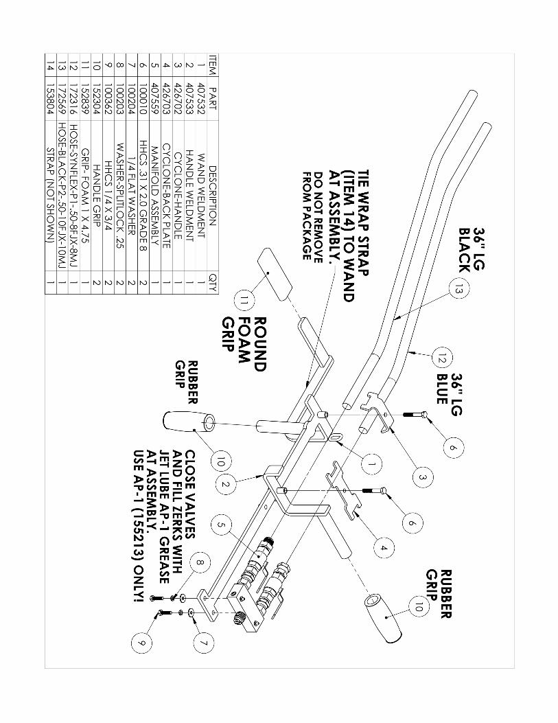
Large Replacement Parts: Front Tire 140521 Caster 140459 Hose-Part 1 (Blue) Hose-Part 2 (Black) 30 FT 172314 30 FT 172568 3 FT 172316 3 FT 172569 Hose (from Pump to Boxes) 153332 Fitting-Black (Part 1) 155196 Fitting-Gray (Part 2) 155197 Grease Gun-Pistol Grip 155212 Grease Tube 14 OZ 155213 Hose Clamp 152158 Coupling Guard 426685S
8
9
Ro
yal Cyclo
ne
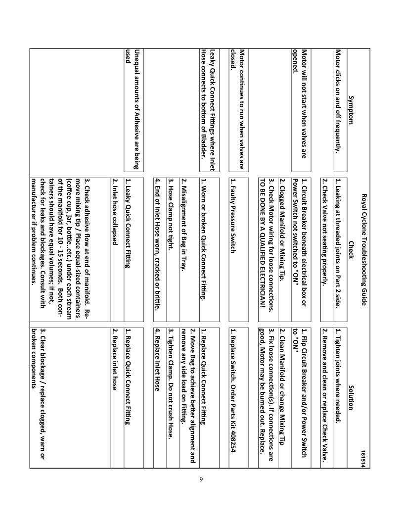
Trou
ble
sho
oti
ng G
uid
e
161514
Symp
tom
Ch
eck
So
luti
on
Mo
tor clicks o
n an
d o
ff freq
uen
tly.
1. Le
aking at th
read
ed
join
ts on
Part 2
side
.
1. Tigh
ten
join
ts wh
ere need
ed.
2. C
he
ck Valve
no
t seati
ng p
rop
erly.
2
. Re
mo
ve and
clean o
r replace C
heck V
alve.
Mo
tor w
ill no
t start wh
en valves are
o
pen
ed.
1
. Circu
it Bre
aker ben
eath
ele
ctrical bo
x or
Po
we
r Switch
no
t switch
ed to
"ON
"
1. Flip
Circu
it Breaker an
d/o
r Po
we
r Switch
to
"ON
"
2. C
logge
d M
anifo
ld o
r Mixin
g Tip.
2
. Clean
Man
ifold
or ch
ange M
ixing Tip
3. C
he
ck Mo
tor w
iring fo
r loo
se co
nn
ecti
on
s. TO
BE D
ON
E BY
A Q
UA
LIFIED ELEC
TRIC
IAN
!
3. Fix lo
ose co
nn
ectio
n(s). If co
nn
ectio
ns are
go
od
, Mo
tor m
ay be b
urn
ed o
ut. R
eplace.
Mo
tor co
nti
nu
es to ru
n w
hen
valves are
closed
.
1. Fau
lty Pre
ssure
Switch
1. R
ep
lace Switch
. Ord
er Parts K
it 40825
4
Leaky Q
uick C
on
nect Fitti
ngs w
here In
let H
ose co
nn
ects to b
ott
om
of B
ladd
er.
1. W
orn
or b
roken
Qu
ick Co
nn
ect Fitti
ng.
1
. Re
place Q
uick C
on
nect Fitti
ng
2. M
isalignm
en
t of B
ag in Tray.
2
. Mo
ve Bag to
achieve b
etter align
me
nt an
d
rem
ove an
y side lo
ad o
n Fitti
ng.
3. H
ose
Clam
p n
ot ti
ght.
3
. Tighte
n C
lamp
. Do
no
t crush
Ho
se.
4. En
d o
f Inle
t Ho
se w
orn
, cracked o
r britt
le.
4
. Re
place In
let Ho
se
Un
equ
al amo
un
ts of A
dh
esive are b
eing
used
1. Le
aky Qu
ick Co
nn
ect Fitti
ng
1
. Re
place Q
uick C
on
nect Fitti
ng
2. In
let h
ose
collap
sed
2. R
ep
lace inlet h
ose
3. C
he
ck adh
esive
flo
w at e
nd
of m
anifo
ld. R
e-
mo
ve m
ixing ti
p / P
lace e
qu
al-sized
con
taine
rs (co
ffe
e cu
p, jar, b
ott
le..e
tc.) un
de
r each
stream
o
f the m
anifo
ld fo
r 10
- 15
seco
nd
s. Bo
th co
n-
taine
rs sho
uld
have
eq
ual vo
lum
es; if n
ot,
che
ck for le
aks and
blo
ckages. C
on
sult w
ith
man
ufactu
rer if p
rob
lem
con
tin
ue
s.
3. C
lear blo
ckage / replace clo
gged, w
arn o
r b
roken
com
po
nen
ts

10

11
This page intentionally left blank to allow equipment owner to remove back page of manual and turn it in to register for warranty.

12