rp lecture6and7
TRANSCRIPT

1
3. Resistance of a Ship3.1 Model testing
• Resistance of a ship:
– Total resistance
• V Speed of the ship
• L Length of the ship
• Density of the fluid
• Kinematic viscosity of the fluid
• g Acceleration of gravity
),,,,( gLVfRT νρ=
ρ
ν

2
3. Resistance of a Ship3.1 Model testing
• Dimensional analysis
– Total resistance coefficient
• Total resistance coefficient
(S = Wetted surface)
• Reynolds number
• Froude number
),( nnTT FRCC =
SV
RC T
T 22/1 ρ=
ν
VLRn =
gL
VFn =

3
• Equal non-dimensional numbers.
- Reynolds number: (same fluid)
- Froude number:
• Conclusion: it is impossible to satisfy simultaneously the
equality of Reynolds and Froude numbers.
• The model dimensions do not allow the equality of the
Reynolds number for model testing.
sm
smnn V
L
LVRR
ms=⇒=
ss
mmnn V
L
LVFF
ms=⇒=
3. Resistance of a Ship3.1 Model testing
Flow similarity

4
• Resistance force is measured at model scale (model) and
extrapolated for full scale (ship).
• Measurements are performed with the equality of the
Froude number at model and full scale (Froude scaling):
• is the scale factor.
• Model’s length is determined by the geometrical
properties of the towing tank.
sm VV 2/1−= α
ms LL /=α
3. Resistance of a Ship3.1 Model testing
Resistance tests
mL

5
• The length of the model should try to minimize the
difference in Reynolds number (maximum length) within
the limits imposed by the towing tank dimensions.
– The precision of the measurements increases with the
growth of the model.
– Model dimensions are limited by the depth (h) and
width (b) of the towing tank section to avoid a
significant influence of the bottom and side walls.
3. Resistance of a Ship3.1 Model testing
Resistance tests

6
• Typical model dimensions:
h: depth
b: width
Area of the model’s midsection < 1/200 bh
– With the reduction of the ship’s length it becomes
difficult to avoid a significant region of laminar flow.
• At full scale, the flow is nearly “fully-turbulent” (region of
laminar flow at the bow is negligible). Therefore, model
testing should avoid laminar flow.
hLm <
2/bLm <
3. Resistance of a Ship3.1 Model testing
Resistance tests

7
• For the typical Reynolds number of model testing (106 to
107), transition to turbulence must be stimulated:
– Trip wires, studs or roughness strips applied at the bow.
These devices introduce an added resistance that has to
be estimated to correct the measured resistance.
– Turbulence of the outer flow may be increased with the
use of grids or bars in the incoming flow.
3. Resistance of a Ship3.1 Model testing
Resistance tests
8
3. Resistance of a Ship3.1 Model testing
Resistance tests
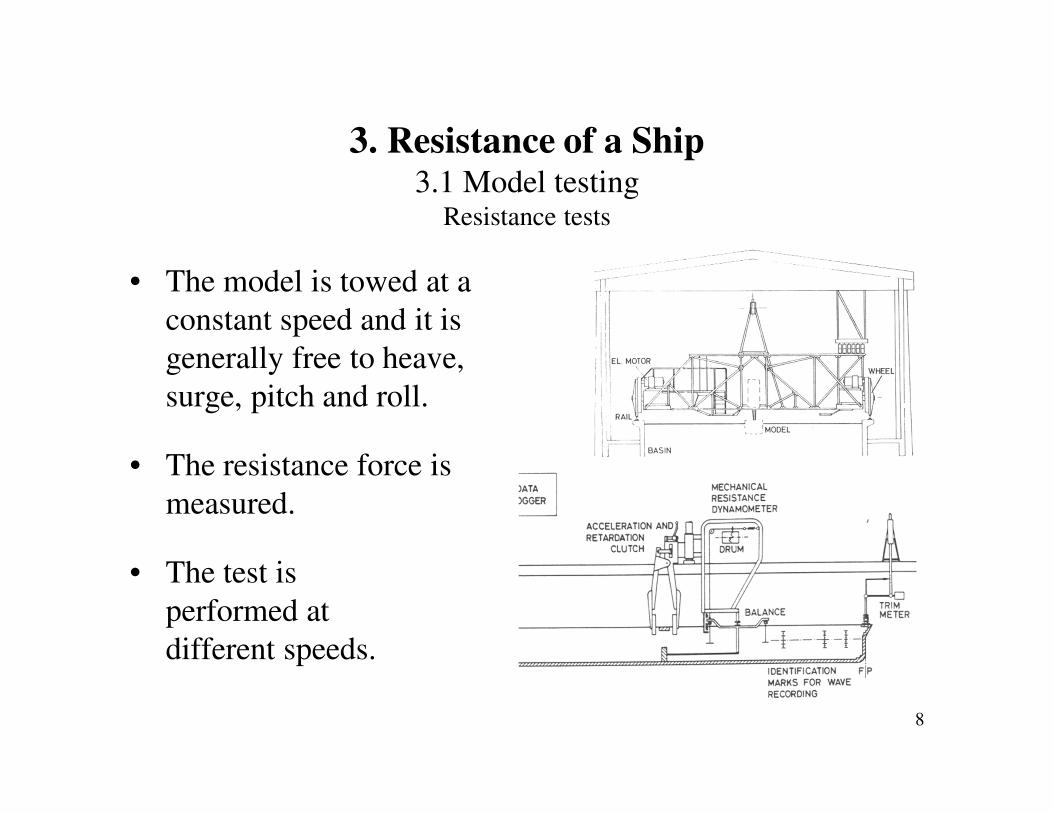
• The model is towed at a
constant speed and it is
generally free to heave,
surge, pitch and roll.
• The resistance force is
measured.
• The test is
performed at
different speeds.

9
3. Resistance of a Ship3.1 Model testing
Resistance tests

10
3. Resistance of a Ship3.1 Model testing
Resistance tests

11
3. Resistance of a Ship3.1 Model testing
Resistance tests

12
3. Resistance of a Ship3.1 Model testing
Resistance tests

13
3. Resistance of a Ship3.1 Model testing
Resistance tests

14
Examples:
http://www.youtube.com/watch?v=Uc35JROubRM&feature=related
http://www.youtube.com/watch?v=MLc-NRKYqis&feature=related
http://www.youtube.com/watch?v=Odkc4ic6jds
http://www.youtube.com/watch?v=RQfzXdTuceY&feature=related
3. Resistance of a Ship3.1 Model testing
Resistance tests

15
3. Resistance of a Ship3.1 Model testing
Resistance tests

16
3. Resistance of a Ship3.1 Model testing
Resistance tests

17
3. Resistance of a Ship3.1 Model testing
Resistance tests

18
3. Resistance of a Ship3.1 Model testing
Resistance tests

19
• Resistance has two contributions:
– Friction resistance.
(Shear-stress at the wall)
– Pressure (residual) resistance.
(Pressure distribution on the ship surface)
• Non-dimensional coefficients:
),()(),( nnRnFnnT FRCRCFRC +=
3. Resistance of a Ship3.1 Model testing
Resistance components

20
• Froude’s Hypothesis:
– The friction resistance may be calculated from the flow
over a flat plate with the same length of the ship
(equality of Reynolds number) and the same wetted
surface. All the rest is residual resistance.
– The residual resistance is independent of the Reynolds
number, i.e. it depends only on the Froude number.
)()(),( nRnFnnT FCRCFRC +=
3. Resistance of a Ship3.1 Model testing
Resistance components. Froude’s hypothesis

21
• Model scale:
– Total resistance coefficient:
– Friction resistance coefficient:
– Residual resistance coefficient:
mmm
TT
SV
RC m
m 22/1 ρ
=
)(mm nFF RCC =
mm FmTR CCC −=
3. Resistance of a Ship3.1 Model testing
Resistance components. Froude’s hypothesis
22
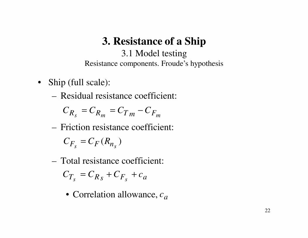
• Ship (full scale):
– Residual resistance coefficient:
– Friction resistance coefficient:
– Total resistance coefficient:
• Correlation allowance,
mms FmTRR CCCC −==
)(ss nFF RCC =
aFsRT cCCCss
++=
ac
3. Resistance of a Ship3.1 Model testing
Resistance components. Froude’s hypothesis

23
• Schoenherr:
• ITTC 1957:
)log(242,0
Fn
F
CRC
×=
210 )2(log
075,0
−=
n
FR
C
3. Resistance of a Ship3.1 Model testing
Extrapolation of the friction resistance

24
3. Resistance of a Ship3.1 Model testingGeosims Lucy Ashton

25
3. Resistance of a Ship3.1 Model testing
Geosims Simon Bolivar

26
CT
nRlog
3. Resistance of a ShipResistance components
Froude’s method

27
C F
C R
C T
log R
F>0
F=0
Resistência
de forma
wFT CCkC ++= )1(
Form (“viscous pressure”) resistance coefficient: kCF
1+k: Form factor
3. Resistance of a ShipResistance components
Viscous pressure resistance “Form drag”

28
CT
nRlog
3. Resistance of a ShipResistance components
Hughes’s method

29
• Wave resistance coefficient
is proportional to
• Total resistance coefficient:
• Therefore,
4nF
4)1( nFT cFCkC ++=
F
n
F
T
C
Fck
C
C4
)1( ++=
F
T
C
C
3. Resistance of a Ship3.1 Model testing
Deteremination of form factor Prohaska’s method
F
n
C
F4

30
• Model scale:
– Total resistance coefficient:
– Friction resistance coefficient. ITTC line:
– Form factor 1+k,viscous resistance coefficient:
– Wave resistance coefficient:
mmm
TT
SV
RC m
m 22/1 ρ
=
)(mm nFF RCC =
mm FmTw CkCC )1( +−=
3. Resistance of a Ship3.1 Model testing
Extrapolation of the Resistance, ITTC method
( )mFV CkC += 1

31
• Ship (full scale):
– Wave resistance coefficient:
– Form factor 1+k independent of Reynolds number.
– Friction resistance coefficient, ITTC line:
– Total resistance coefficient:
• Correlation allowance
ms ww CC =
)(ss nFF RCC =
awFT cCCkCsss
+++= )1(
ac
3. Resistance of a Ship3.1 Model testing
Extrapolation of the Resistance, ITTC method

32
• Roughness effects on the wall shear-stress of a turbulent flow:
– For typical roughness heights smaller than the thickness
of the viscous sub-layer (region with negligible Reynolds
stresses), the wall shear-stress is not affected by the
roughness of the wall, hydrodynamically smooth wall.
sk
ρ
τ
ν
τ
τ
w
s
u
ukk
=
<≡+ 5
3. Resistance of a Ship3.1 Model testing
Roughness effects

33
• Roughness effects on the wall shear-stress of a turbulent flow:
– For typical roughness heights much larger than the
thickness of the viscous sub-layer (region with negligible
Reynolds stresses), the wall shear-stress becomes
independent of the Reynolds number and essentially
determined by the roughness height, fully-rough regime.
sk
8070 −>≡+
ντuk
k s
3. Resistance of a Ship3.1 Model testing
Roughness effects

34
• Roughness effects on the wall shear-stress of a turbulent flow:
– Equivalent sand-grain roughness height, , of a given
surface is the height of an evenly distributed sand-grain
roughned flat plate that produces the same resistance of the
selected surface. This is a single parameter definition of
roughness that is not easy to obtain for real ship surfaces. A
recently painted ship has a typical value of ksg=30µm,
which is equivalent to 150µm for the average roughness
height, kM, (the typical roughness height measured in
shipyards).
sgk
3. Resistance of a Ship3.1 Model testing
Roughness effects

35
• Roughness effects on the wall shear-stress of a turbulent flow:
– The non-dimensional parameter used to quantify roughness
effects is the Reynolds number based on the roughness
height
ν
sg
k
VkR =
3. Resistance of a Ship3.1 Model testing
Roughness effects

36
3. Resistance of a Ship3.1 Model testing
Roughness effects

37
• Roughness effects on the wall shear-stress of a turbulent flow:
– Near-wall non-dimensional roughness parameter depends
on the Reynolds number of the flow
– Model testing is perfomed with “hydrodynamically
smooth” surfaces.
– Full scale ships have rough surfaces.
3. Resistance of a Ship3.1 Model testing
Roughness effects
9.0
1.0
17.02
Ls
Lsfs R
L
k
L
xR
L
kCkuk
−
+
≈==
ντ

38
• Roughness effects are covered by the correlation allowance, .
• The correlation allowance is not only a “roughness correction”.
Each model basin uses its “know-how” to determine .
• Holtrop’s formula for the correlation allowance:
• Bowden and Davison formula:
ac
ac
00205.0)100(006.016,0
−+=−
wla Lc
3. Resistance of a Ship3.1 Model testing
Roughness effects
00064.0105.0
31
−
=
PP
Ma
L
kc

39
• Resistance tests are frequently performed with the rudder
and the remaining appendages (shaft brackets, bilge keels,
fins, etc).
• The appendages contribute to the wetted surface of the ship.
• The Reynolds number based on the ship length (and
undisturbed velocity) is not representative of the local flow
on the appendages. In general, due to the smallest
dimensions of the appendages, the local flow has a smaller
Reynolds number than the ship flow.
3. Resistance of a Ship3.1 Model testingAppendage resistance

40
• The extrapolation of the resistance based on a friction
resistance dependent on the Reynolds number and an equal
form factor at model and full scale, may not be applicable to
each appendage separately.
• Due to the small size of the appendages at model scale, it
may be impossible to avoid laminar flow on the appendages
for the lowest velocity tests, required to determine the form
factor. At full scale, the flow will be “fully-turbulent” on the
appendages.
3. Resistance of a Ship3.1 Model testingAppendage resistance

41
• An alternative way to determine the viscous pressure
resistance of the appendages (“form drag”) is to perform
two model scale tests at high speed for a bare hull and a
fully-appended model. Assuming that the wave resistance is
equal in both models and that the friction resistance
component may be corrected according to the wetted
surface of the two models, the difference between the
resistance of the two tests gives a measure of the viscous
pressure resistance of the appendages.
3. Resistance of a Ship3.1 Model testingAppendage resistance