rpp-rpt-52352 - rev 02 - fe&c€¦ · · 2016-09-264. usq number n/a ... document release and...
TRANSCRIPT

DOCUMENT RELEASE AND CHANGE FORM Prepared For the U.S. Department of Energy, Assistant Secretary for Environmental Management By Washington River Protection Solutions, LLC., PO Box 850, Richland, WA 99352 Contractor For U.S. Department of Energy, Office of River Protection, under Contract DE-AC27-08RV14800
1a. Doc No: RPP-RPT-52352 Rev. 02
1b. Project Number: N/A
1 SPF-001 (Rev.0)
TRADEMARK DISCLAIMER: Reference herein to any specific commercial product, process, or service by trade name, trademark, manufacturer, or otherwise, does not necessarily constitute or imply its endorsement, recommendation, or favoring by the United States government or any agency thereof or its contractors or subcontractors. Printed in the United States of America.
Release Stamp
2. Document Title
242-A Evaporator E-A-1 Reboiler - Functions and Requirements Evaluation Document
3. Design Verification Required
Yes No
4. USQ Number N/A 5. PrHA Number N/A
EV-14-1599-D R-0 PRHA-01972 Rev. 00
6. USQ Screening:
a. Does the change introduce any new failure modes to the equipment? Yes No
Basis is required for Yes:
b. Does the change increase the probability of existing failure modes? Yes No
Basis is required for Yes:
c. For Safety Significant equipment, does the change require a modification to Chapter 4 of the DSA and/or FRED? Yes No N/A
Basis is required for Yes: More information included in FRED about existing failure mechanism. No change to DSA Required.
7. Description of Change and Justification (Use Continuation pages as needed)
More information included in FRED about existing failure mechanism.
8. Approvals
Title Name Signature Date
Clearance Review PHILLIPS, TIFFANY M PHILLIPS, TIFFANY M 08/22/2014
Design Authority BROWN, TODD M BROWN, TODD M 08/21/2014
Checker OLSON, WILL T OLSON, WILL T 08/21/2014
Document Control Approval PHILLIPS, TIFFANY M PHILLIPS, TIFFANY M 08/22/2014
Originator BECKER, BRENT T BECKER, BRENT T 08/21/2014
Other Approver GRIGSBY, J MIKE GRIGSBY, J MIKE 08/21/2014
Other Approver GOESSMANN, GLEN E GOESSMANN, GLEN E 08/21/2014
Other Approver ZINTER, DONALD D ZINTER, DONALD D 08/21/2014
PrHA Lead KOZLOWSKI, STEPHEN D KOZLOWSKI, STEPHEN D 08/21/2014
Responsible Engineering Manager PICKLES, TOM R PICKLES, TOM R 08/22/2014
Please see continuation sheet
9. Clearance Review:
Restriction Type:
Public
Undefined
Unclassified Controlled Nuclear Information (UCNI)
Export Control Information (ECI)
Official Use Only Exemption 2-Circumvention of Statute (OUO-2)
Official Use Only Exemption 3-Statutory Exemption (OUO-3)
Official Use Only Exemption 4-Commercial/Proprietary (OUO-4)
Official Use Only Exemption 5-Privileged Information (OUO-5)
Official Use Only Exemption 6-Personal Privacy (OUO-6)
Official Use Only Exemption 7-Law Enforcement (OUO-7)
RPP-RPT-52352 8/22/2014 - 3:28 PM 1 of 40
Release Stamp
Aug 22, 2014
DATE:
DOCUMENT RELEASE AND CHANGE FORM Doc No: RPP-RPT-52352 Rev. 02
2 SPF-001 (Rev.0)
10. Distribution:
Name Organization
BECKER, BRENT T ELECTRICAL/AREA/242A-EVAP ENG
BROWN, TODD M COGNIZANT SYSTEM ENGINEERING
GOESSMANN, GLEN E ENGRNG PROGRAMS & STANDARDS
GRIGSBY, J MIKE NUCLEAR SAFETY
OLSON, WILL T ELECTRICAL/AREA/242A-EVAP ENG
PICKLES, TOM R ELECTRICAL/AREA/242A-EVAP ENG
ZINTER, DONALD D DESIGN ENGINEERING
11. TBDs or Holds N/A
12. Impacted Documents – Engineering N/A
Document Number Rev. Title
13. Other Related Documents N/A
Document Number Rev. Title
ECN-11-002072 00 242-A Evaporator Reboiler Steam Condensate System Upgrade
H-2-69280 SH 001 01 STRUCTRUAL SECOND FLOOR PLAN SECTIONS AND DETAILS AREAS 1 AND 2
H-2-69281 SH 001 01 STRUCTURAL PLANS/PLATFORMS/SECTIONS AND DETAILS AREAS 1 AND 2
H-2-69285 SH 001 01 STRUCTURAL SECTIONS AND DETAILS AREAS 1 AND 2
H-2-98988 SH 002 16 P&ID EVAP RECIRC SYSTEM
H-2-98992 SH 001 35 P&ID STEAM SYSTEM
H-2-98993 SH 001 31 P&ID STEAM CONDENSATE SYSTEM
H-2-98995 SH 002 11 P&ID DRAIN SYSTEM
H-2-99001 SH 001 26 P&ID PROCESS & INSTR AIR SYSTEM
H-2-99001 SH 002 13 P&ID PROCESS & INSTR AIR SYSTEM
RPP-48900 00A 242-A Evaporator Hazard Evaluation Database Report
RPP-CALC-48552 02A Jumper Assembly C to 4-40 & 4 to 5/40 to 21 Calculation Package
RPP-CALC-57003 00 Fluorescein Tracer Test Analysis
RPP-RPT-41041 00 TECHNICAL EVALUATION OF THE 242-A EVAPORATOR FACILITY STEAM AND STEAM CONDENSATE SYSTEMS
RPP-RPT-52517 00 242-A EVAPORATOR FACILITY ASSESSMENT FOR PERFORMANCE CATEGORY 2 NATURAL PHENOMENA HAZARDS
RPP-RPT-57257 00 Test Report for Leak-Tightness of Reboiler Vessel E-A-1 at 242-A Evaporator Facility
RPP-RPT-58179 00 Evaluation of Halide Stress Corrosion Cracking and Pitting in the 242-A E-A-1 Reboiler as it Related to Operating
Parameters and Tank Waste Chemistry
RPP-TE-54842 01 242-A Evaporator E-A-1 Reboiler Upgrade to Safety Significant QL-2
14. Related Systems, Structures, and Components:
14a. Related Building/Facilities N/A
242-A EVAPORATOR FACILITIES
14b. Related Systems N/A
242A
242A-PA
242A-SC
242A-STM
14c. Related Equipment ID Nos. (EIN) N/A
E-A-1
RPP-RPT-52352 8/22/2014 - 3:28 PM 2 of 40

3 SPF-001 (Rev.0)
DOCUMENT RELEASE AND CHANGE FORM CONTINUATION SHEET
Document No: RPP-RPT-52352 Rev. 02
8. Approvals
Title Name Signature Date
USQ Evaluator KOZLOWSKI, STEPHEN D KOZLOWSKI, STEPHEN D 08/22/2014
N/A
RPP-RPT-52352 8/22/2014 - 3:28 PM 3 of 40
A-6002-767 (REV 3)
RPP-RPT-52352, Rev. 2
242-A Evaporator E-A-1 Reboiler - Functions and Requirements Evaluation Document
Author Name:
B.T. Becker
Richland, WA 99352 U.S. Department of Energy Contract DE-AC27-08RV14800
EDT/ECN: N/A UC: N/A
Cost Center: N/A Charge Code: N/A
B&R Code: N/A Total Pages: 37
Key Words: 242-A, Evaporator, E-A-1, Reboiler, Piping, Safety-Significant, Primary, Boundary, Critical Characteristics, Controls, Safety Equipment Compliance Database (SECD), FRED
Abstract: RPP-RPT-42352, "242-A Evaporator E-A-1 Reboiler - Functions and Requirements Evaluation Document" established the safety related functions and requirements for evaluating the 242-A Evaporator
E-A-1 Reboiler's ability to perform its required safety function.
TRADEMARK DISCLAIMER. Reference herein to any specific commercial product, process, or service by trade name, trademark, manufacturer, or otherwise, does not necessarily constitute or imply its endorsement, recommendation, or
favoring by the United States Government or any agency thereof or its contractors or subcontractors.
Release Approval Date Release Stamp
Approved For Public Release
RPP-RPT-52352 8/22/2014 - 3:28 PM 4 of 40
By Tiffany Phillips at 3:31 pm, Aug 22, 2014
Aug 22, 2014
DATE:
RPP-RPT-52352 8/22/2014 - 3:28 PM 5 of 40

RPP-RPT-52352
Rev. 2
242-A Evaporator E-A-1 Reboiler – Functions
and Requirements Evaluation Document
B. T. Becker
Washington River Protection Solutions, LLC
Date Published
August 21, 2014
Prepared for the U.S. Department of Energy
Office of River Protection
Contract No. DE-AC27-08RV14800
RPP-RPT-52352 8/22/2014 - 3:28 PM 6 of 40
RPP-RPT-52352, Rev. 2
ii
TABLE OF CONTENTS
1.0 PURPOSE ....................................................................................................................... 1
2.0 APPROACH ................................................................................................................... 1
3.0 SCOPE ............................................................................................................................ 2
4.0 SAFETY FUNCTION ..................................................................................................... 2
5.0 SYSTEM DESCRIPTION ............................................................................................... 3
5.1 OVERALL DESCRIPTION ................................................................................ 3
5.2 BOUNDARIES .................................................................................................... 5
5.3 INTERFACES ..................................................................................................... 5
6.0 SYSTEM EVALUATION ............................................................................................... 6
6.1 FUNCTIONAL/PERFORMANCE REQUIREMENTS ........................................ 6
6.2 FAILURE MODE EVALUATIONS .................................................................... 7
6.2.1 Failure Modes and Effects Analysis .......................................................... 7
6.2.2 Failures Modes and Mechanisms of E-A-1 Reboiler ................................. 8
6.2.3 Mechanisms of E-A-1 Reboiler Failure ..................................................... 9
6.2.4 Other Failure Modes ............................................................................... 14
6.2.5 Failure Modes and Mechanisms of Sample Analysis............................... 14
6.2.6 Aging ..................................................................................................... 15
6.3 SUPPORTING SYSTEMS ................................................................................ 15
7.0 CONTROLS .................................................................................................................. 15
7.1 CONTROLS ...................................................................................................... 16
8.0 CRITICAL CHARACTERISTICS ................................................................................ 16
9.0 REFERENCES .............................................................................................................. 16
APPENDIX A E-A-1 REBOILER FMEA ................................................................................ A1
APPENDIX B LABORATORY SAMPLE ANALYSIS FMEA ............................................... B1
APPENDIX C 242-A EVAPORATOR E-A-1 REBOILER DESIGN REQUIREMENTS ........ C1
APPENDIX D E-MAIL STATEMENT OF MAXIMUM DISCHARGE TEMPERATURE ..... D1
RPP-RPT-52352 8/22/2014 - 3:28 PM 7 of 40
RPP-RPT-52352, Rev. 2
iii
LIST OF FIGURES
Figure 1. 242-A Reboiler and Interfacing Systems .................................................................... 4
LIST OF TABLES
Table 6-1. Failure Modes of the E-A-1 Reboiler ........................................................................ 8
Table 6-2. Failure Modes for Laboratory Analysis....................................................................15
Table 8-1, Critical Characteristics of the E-A-1 Reboiler ...........................................................16
RPP-RPT-52352 8/22/2014 - 3:28 PM 8 of 40

RPP-RPT-52352, Rev. 2
iv
LIST OF TERMS
Acronyms and Abbreviations
ASME American Society of Mechanical Engineers
ASTM American Society for Testing and Materials
C Centigrade
C of C Certificate of Conformance
DOE Department of Energy
DST Double Shell Tank
F Fahrenheit
gpm gallons per minute
HIHTL Hose-in-Hose Transfer Line
HVAC Heating, Ventilation, Air Conditioning
IQRPE Independent Qualified Registered Professional Engineer
LPG Liquid Propane Gas
NCR Non-conformance report
PRV Pressure Relief Valve
psig pounds per square inch – gauge
PTFE Polytetrafluoroethylene
PUREX Plutonium Uranium Extraction
SECD Safety Equipment Compliance Database
SpG Specific Gravity
SSCs Structures, Systems, and Components
TEDF Treatment Effluent Disposal Facility
TEMA Tube Exchanger Manufacturers Association
TOC Tank Operations Contractor
VFD Variable Frequency Drive
WRPS Washington River Protection Solutions
RPP-RPT-52352 8/22/2014 - 3:28 PM 9 of 40
RPP-RPT-52352, Rev. 2
1
1.0 PURPOSE
The purpose of this document is to describe the evaluation of the E-A-1 Reboiler’s ability to
perform its safety function(s) under those conditions and events for which the safety function is
required. This document identifies the related system, structure, and components (SSCs); critical
characteristics; functional and performance requirements; failure modes; boundaries; interfaces;
required support systems, and the Key aspects.
2.0 APPROACH
The safety function of the E-A-1 Reboiler was developed based on hazardous conditions
identified in RPP-48900, 242-A Evaporator Hazard Evaluation Database Report.
Functional/performance requirements were developed by evaluating the required performance
needed to accomplish the safety functions (i.e., prevent or mitigate accidents). Additional
applicable functional requirements were developed during engineering evaluations of failure
modes when the E-A-1 Reboiler must perform its safety function.
This evaluation was done in accordance with TOC procedure TFC-ENG-DESIGN-C-45,
“Control Development Process for Safety-Significant Structures, Systems, and Components.”
The following information is provided in this document:
1. Identification of the safety-significant boundaries for the E-A-1 Reboiler
2. Documentation of support systems required for the E-A-1 Reboiler to perform the
intended safety function.
3. An evaluation of interfacing systems whose failure could prevent the E-A-1 Reboiler
from performing the intended safety function.
4. Documentation of safety SSC functional and performance requirements necessary for the
E-A-1 Reboiler to perform the safety function. The safety SSC functional and
performance requirements were identified from design requirements, engineering
evaluations and calculations, the interactive hazard/accident analysis safety controls
development/evaluation process, and process hazard analysis.
5. Critical characteristics necessary for the E-A-1 Reboiler to perform the safety functions,
and identification of how the critical characteristics can be verified to be met. Critical
characteristics may be used in the commercial grade dedication (CGD) process to provide
reasonable assurance the safety SSC is acceptable and will perform its safety-related
function.
6. Controls (inspections, tests, evaluations or other provisions) needed to verify compliance
with critical characteristics during fabrication or construction, and provisions necessary
to provide reasonable assurance that PSV-PB2-1 will continue to perform its intended
RPP-RPT-52352 8/22/2014 - 3:28 PM 10 of 40
RPP-RPT-52352, Rev. 2
2
safety function during operation (e.g., in-service inspections, tests, evaluations, shelf life,
service life).
Using information from the evaluation described above, critical characteristics for the E-A-1
Reboiler were identified. Subsequent to determining the critical characteristics, key performance
requirements were identified. This consisted of identifying any inspections, tests, evaluations or
controls needed to verify compliance with critical characteristics.
Compliance with the critical characteristics identified in this Functions and Requirements
Evaluation Document shall be verified and documented. Acceptable means of verification can
be accomplished by one or more of the following means:
· Procurement from a qualified supplier
· Commercial grade dedication
· Technical evaluation (to close an NCR)
NOTE: The NCR process shall be used to upgrade an existing SSC when the SSC was not
procured as safety-significant through a qualified supplier or the CGD process prior to the SSC
being declared safety-significant. A Technical Evaluation (refer to TFC-ENG-FACSUP-C-02)
shall determine how the FRED critical characteristics were verified and shall be listed in the
Safety Equipment Compliance Database (SECD).
Documented evidence of compliance is identified in the SECD (refer to
TFC-ENG-FACSUP-C-23 and TFC-ENG-FACSUP-CD-23.3).
3.0 SCOPE
The scope of this evaluation focuses on the E-A-1 Evaporator Reboiler. This evaluation also
considers interfacing/support systems and the effect they may have on the safety function of the
Reboiler.
4.0 SAFETY FUNCTION
The safety function of the E-A-1 Reboiler is to provide confinement of waste (i.e., E-A-1
Reboiler tube/tube sheet integrity). Providing confinement of waste protects facility workers
from a flammable gas accident in the steam condensate system due to waste in the steam
condensate system resulting from an E-A-1 Reboiler tube/tube sheet leak/failure (i.e.,
accumulation of flammable gas generated by waste in the steam condensate system piping or
components). Providing confinement of waste also protects facility workers from direct
radiation hazards and chemical burn hazards (i.e., skin contact with caustic waste) during steam
condensate sampling activities due to waste in the steam condensate system resulting from an E-
RPP-RPT-52352 8/22/2014 - 3:28 PM 11 of 40
RPP-RPT-52352, Rev. 2
3
A-1 Reboiler tube/tube sheet leak. (Note: The direct radiation hazard is only from waste
misrouted into steam condensate weir box TK-C-103.)
5.0 SYSTEM DESCRIPTION
5.1 OVERALL DESCRIPTION
The 242-A Evaporator is designed to reduce the waste volume that must be stored in Hanford
Tank Farms double-shell tanks (DSTs). This is accomplished through an evaporation process
that uses a conventional forced-circulation, vacuum evaporation system operating at low pressure
to concentrate radioactive waste solutions.
The waste is pumped from feed tank 241-AW-102 through an underground line to the 242-A C-
A-1 liquid/vapor vessel for reduction. While under vacuum (40-80 torr), waste is heated in a
steam heated Reboiler to a temperature of approximately 120°F. In the C-A-1 vessel, excess
water flashes to steam creating product slurry and water vapor. The slurry is transferred from the
242-A Evaporator by the P-B-2 slurry pump, through underground piping, to the 241-AW-B
valve pit in the 241-AW Tank Farm. From this valve pit, slurry can be further directed to one of
the 25 double shell tanks in the 200 East Area.
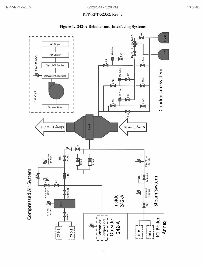
The E-A-1 Reboiler (see Figure 1) is a single pass shell and tube heat exchanger with 2000 ft2 of
conductive surface area. It is positioned in the 28” recirculation loop within the 242-A
Evaporator Room in a vertical orientation. Because the Reboiler is located downstream of the P-
B-1 recirculation pump, waste enters the Reboiler at the bottom of the heat exchanger, flows
through the internal tubes where it exits at the top of the exchanger, and enters the C-A-1
Evaporator Vessel. Concurrently, counter flowing steam enters at the top of the heat exchanger
and exits at the bottom of the exchanger. As a heat exchanger, the E-A-1 Reboiler has two
pressure temperature ratings. The first rating, for the shell side of the exchanger, limits shell and
external tube pressure to 100 psig at maximum temperature of 350°F. The second rating, for the
tubes, limits internal tube pressure to full vacuum to 20 psig at a maximum temperature of
250°F.
Two dedicated 15 psig boilers provide 11-12 psig saturated steam to the Reboiler. During the
heating process steam is reduced to condensate in the Reboiler. Condensate then drains to the
Treated Effluent Disposal Facility (TEDF), via Tank 103, or is diverted to 241-AW-102 upon
detection of radiation in the condensate.
RPP-RPT-52352 8/22/2014 - 3:28 PM 12 of 40
RPP-RPT-52352, Rev. 2
4
Figure 1. 242-A Reboiler and Interfacing Systems
RPP-RPT-52352 8/22/2014 - 3:28 PM 13 of 40

RPP-RPT-52352, Rev. 2
5
5.2 BOUNDARIES
The E-A-1 Reboiler is welded into the Evaporator recirculation loop, making it an integral
component of the system. An obvious boundary for this component exists at the tube sheets
where the waste enters and exits the tube bundle. On each end of the Reboiler are conical
plenums, used to connect the 28” recirculation line to the larger 40” diameter Reboiler. The
steam used for heating is on the shell side of the exchanger while waste flows through the tubes.
Thus, the waste boundary exists at the tube sheets and the exchanger tubes which maintain
separation between the two fluid streams. The steam side boundary exists at the flanges
connecting the shell branch inlet and outlet to associated steam and condensate piping.
5.3 INTERFACES
The saturated steam system, steam condensate system and the process air system interface with
the Reboiler, and are depicted in Figure 1. Steam is provided to the 242-A Evaporator facility by
the Johnson Controls Industries (JCI) Boiler Annex. Inside of the Annex are two boilers capable
of producing saturated steam at 15 psig and one boiler capable of producing saturated steam at
90 psig. Saturated steam at 15 psig corresponds to temperature of 250°F which is the design
temperature of the Reboiler tube bundle. Saturated steam at 90 psig (used to create the vacuum
in the C-A-1 liquid vapor separator vessel) corresponds to a temperature of 331.13°F, which
exceeds the design temperature of the tube bundle. Because the 90 psig boiler has the potential
for exceeding the design temperature, this boiler cannot be used as a source of steam for the
Reboiler. To eliminate this boiler as a failure mode, the 90 psig steam line has been isolated
from the dedicated Reboiler steam system.
Each of the low pressure boilers are protected by a pressure relief valve with a set pressure of 15
psig. These valves are designed, manufactured and installed in accordance with ASME Section
VIII, Division 1, UG-125. Further downstream, and within the 242-A Evaporator facility, are
two additional pressure relief valves (PSV-EA1-2 and PSV-EA1-4 (H-2-98992, P&ID Steam
System)) set at 20 psig. These valves too, are designed, manufactured and installed in
accordance with ASME requirements.
The process air system is comprised of two rotary air compressors rated at 100 scfm (min) at 100
psig. Each compressor has a pressure safety valve rated at 155 psig. Located in the AMU room,
these compressors are connected to the R-E-1 air receiver via a 1-1/4” supply line (H-2-99001,
P&ID Process & Instrument Air System). Upon failure of the in-plant compressors, portable
compressors can be connected to the Process Air header downstream of the air receiver. In
addition to both compressor relief valves, the air receiver is fitted with a 125 psig pressure relief
valve. If portable air compressors are used, HV-RE1-8A must remain open. In this manner the
R-E-1 pressure safety valve will aid in protecting the system. From the air receiver, air is
delivered to the Reboiler via solenoid valve HV-EA1-3. When steam flow is isolated from the
Reboiler, valve HV-EA1-3 opens and 18 psig air is provided to the Reboiler shell. When process
activities are ongoing, and steam is supplied to the Reboiler, solenoid valve HV-EA1-3 closes to
isolate the air to the Reboiler. Two vacuum breakers PSV-1 and PSV-2 connected to the steam
feed line prevent vacuum from forming in the event of a steam column collapse.
RPP-RPT-52352 8/22/2014 - 3:28 PM 14 of 40
RPP-RPT-52352, Rev. 2
6
6.0 SYSTEM EVALUATION
6.1 FUNCTIONAL/PERFORMANCE REQUIREMENTS
The functional requirement for the E-A-1 Reboiler is no leakage of waste (leak tight pressure
boundary). This is accomplished by using a vessel that is designed to the requirements of ASME
Section VIII, Division 1. The 242-A Evaporator Reboiler has been in service for over thirty
years. Prior to being placed in service, the Reboiler was pressure tested to 1.5 times the design
pressure (Certified Vendor file CVI-20253, RPP-TE-54842). Thus, the integrity of the design is
not under scrutiny, but rather, the integrity of components due to potential degradation with use.
Based on design life and operating conditions, the ability of the E-A-1 Reboiler to perform its
safety function can degrade and periodic testing is required.
IQRPE conducts evaluations of transfer lines and Evaporator recirculation loop piping every ten
years. Acknowledging that the transfer lines are schedule 40 pipe (0.154” wall) and the Reboiler
tubes are 14 gage (0.083” wall – roughly half the thickness of pipe), the test frequency for the
Reboiler tubes is reduced to half of that for transfer lines. Further reduction in the test frequency
is not warranted as UT measurements of the recirculation loop indicate little or no
corrosion/erosion has occurred since operations have begun. A test frequency of 5 years is
judged to be practical since corrosion of the tubes/tubesheet will not result in leakage of sufficient
magnitude to result in a significant facility worker hazard over the functional test frequency.
Steam chest pressure is approximately atmospheric during processing operations. Losing
process vacuum would bring full atmospheric pressure to bear on the waste in the C-A-1 vessel,
thus increasing the waste pressure at the Reboiler tubes and tube sheets. At atmospheric pressure
in the C-A-1 vessel, the waste hydrostatic pressure exerted on the tube sheet, and thus the lower
end of the tubes, is calculated to be 13.37 psi. The pressure drop as waste flows through the
exchanger tubes is calculated to be 3.4 psi with a fluid specific gravity of 1.6. The combined
pressure is therefore 16.77 psi, which is the differential pressure across the tube/tubesheet to the
shell side of the Reboiler when the shell is at atmospheric pressure.
Based on pressure differential established above, the following pneumatic pressure decay test has
been established:
- Pneumatic pressure decay leak test where the shell side is pressurized to 16 - 18 lb2/in
gauge and held for a minimum of 10 min with no decrease in pressure. Consistent with
other pressure decay tests, pressure will be isolated and held for ten minutes with no
decrease in pressure.
Alternatively a liquid trace leak test can be used to verify the integrity of the currently installed
Reboiler. RPP-CALC-57003, Fluorescein Tracer Test Analysis, shows that a liquid trace leak
test is more sensitive than the pressure decay test. The liquid trace leak test is as follows:
- A liquid tracer leak test where tracer (e.g., fluorescein) is mixed into water in the C-A-1
vessel and held for 24 hours with the C-A-1 vessel water level at or above the normal
RPP-RPT-52352 8/22/2014 - 3:28 PM 15 of 40

RPP-RPT-52352, Rev. 2
7
operating level and the E-A-1 Reboiler shell side at atmospheric pressure. The sensitivity
of the test shall not be less than one drop/hr.
6.2 FAILURE MODE EVALUATIONS
6.2.1 Failure Modes and Effects Analysis
To determine the potential failure modes and failure mechanisms of the E-A-1 vessel, a Failure
Modes and Effects Analysis (FMEA) was performed. Failure modes and failure mechanisms of
components were identified. Necessary critical characteristics and controls were then applied to
this safety-significant component.
A failure mode is the manner in which a component of the system may fail. For example, two
failure modes of a pipe is a loss of integrity or plugging. A failure mechanism is the cause of the
failure mode. A failure mode may have several failure mechanisms. For example, a pipe loss of
integrity could be the result of over pressurization, or could result from corrosion. When the
mechanisms for failure are understood, critical characteristics and/or controls may be applied to
ensure that the safety system performs its safety function, without failure. A list of potential
failure mechanisms is provided in Attachment A of TFC-ENG-DESIGN-C-45. These tables
were used to ensure that all potential failure mechanisms were considered.
Attending these FMEA meetings were System and Facility Engineering, Nuclear Safety,
Operations, the Engineering Discipline Lead, and an FMEA facilitator. Personnel from
maintenance, safety, and environmental organizations were invited on an as-needed basis.
Results of the FMEA meetings and subsequent evaluations are listed in Appendix A for the
E-A-1 Reboiler vessel.
Appendix A provides the following information from the FMEA analysis, and the evaluation of
failure mechanisms, critical characteristics and controls:
· Column 1: “Component”. This column lists the components within the safety systems
that were evaluated. Each component in the safety system was evaluated for the effect of
its failure on the safety function of the system.
· Column 2: “Failure Mode”. This column lists the various failure modes that are possible
for the evaluated component from Column 1.
· Column 3: “Effect on (System) Safety Function”. This column lists the effect of the
failure mode on the safety function of the system. Note that not every equipment failure
results in a failure of the system to perform its safety function.
· Column 4: “Consider for Failure Mechanisms”. This column lists a “Yes” or a “No”,
depending upon whether the identified failure was determined to be a failure of the
system to perform its safety function. If a “No” was identified, then there was no further
need to determine the failure mechanisms that could result in failure (see next paragraph).
· Column 5: “Failure Mechanisms”. When an equipment failure has the potential to result
in a failure of the system to perform its safety function, then the possible mechanisms for
RPP-RPT-52352 8/22/2014 - 3:28 PM 16 of 40
RPP-RPT-52352, Rev. 2
8
failure were identified. These mechanisms were chosen based on the experience of the
FMEA group, and upon engineering evaluation of the system.
· Column 6 and 7: “Potential Controls” and “Potential Critical Characteristics”
respectively. These columns represent the controls and critical characteristics that the
team identified to help prevent the identified failure. This column will be used to identify
the final list of controls and critical characteristics at the end of this document.
· Column 8: “Codes/Standards”. This column lists codes and standards that should be
considered when applying a potential critical characteristic or control.
· Column 9: “Notes”. This column includes any information pertinent to the FMEA
discussions. In particular, this column justifies failure modes identified as “fail-safe”
(see next paragraph).
Not all equipment failures result in a failure of the safety system to perform its intended safety
function. An equipment failure mode often results in a failure that is “fail-safe”. That is,
although some failures may cause equipment damage or an instrument reading error, that damage
or error doesn’t result in a failure of the system to perform it safety function. For such “fail safe”
failure modes, failure mechanisms were not considered, and critical characteristics and controls
are not necessary. In Attachment A, these “fail-safe” failures are identified as “safe direction” or
“no failure” in column 3 “Effect on Safety Function” and as a “No” in column 4 “Consider for
Failure Mechanisms”. In column 9 “Notes”, a justification is provided to explain why the failure
mode is considered to be fail-safe.
The next two sections will present the results of the FMEA analysis for the E-A-1 vessel. In
each section, a table is used to summarize which failure modes could affect the ability of the
safety system to perform its safety function. The remainder of the section contains a discussion
of the failure mechanisms and the proposed controls and critical characteristics.
6.2.2 Failures Modes and Mechanisms of E-A-1 Reboiler
An FMEA evaluation of the E-A-1Reboiler vessel was performed, evaluating which system
failures resulted in a failure of the Reboiler to perform its safety function, as stated in
Section 4.0. The discussion of the failure modes, as well as the effect of that failure mode on the
safety function of the system, is shown in Table 6-1, below:
Table 6-1. Failure Modes of the E-A-1 Reboiler
Component Failure Mode
Effect on Reboiler Tube and
Tubesheet Integrity Safety Function
Reboiler Tubes and
Tubesheets
Leak Loss of integrity
Plug None
Failure mechanisms for the failure mode “Leak” are identified below. Critical characteristics
and controls, as well as applicable codes and standards, are also discussed for each failure
mechanism when applicable. Necessary critical characteristics and controls are in bold type.
RPP-RPT-52352 8/22/2014 - 3:28 PM 17 of 40
RPP-RPT-52352, Rev. 2
9
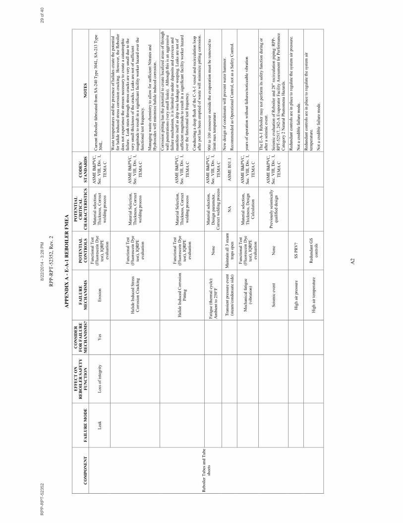
6.2.3 Mechanisms of E-A-1 Reboiler Failure
Mechanism 1 – Erosion of the Tubes, Tube Sheet or Weld
The tube sheet is fabricated from 1-1/4 inch stainless steel plate. The tubes are 14 gauge (0.083
wall) stainless steel seamless tubing. Excessive erosion of either component of the tube bundle
will result in a breach of the safety significant boundary and potentially expose the shell side of
the Reboiler to contamination. However, due to the difference in thickness, it is expected that
the thin walled tubes will be affected by erosion before the tube sheets. Although RPP-RPT-
33306, Independently Qualified Registered Professional Engineer (IQRPE) Integrity Assessment
Report for the 242-A Evaporator Tank System, evaluates the process loop piping, which includes
the Reboiler, only the Reboiler shell is evaluated. Due to the remote nature of the internal tube
bundle, it is not accessible for quantitative evaluation. Rather, the integrity of the tube/tubesheet
will be assessed every five years by testing (see Section 6.1). Since erosion of the
tubes/tubesheet is a slow failure mechanism, a 5-year leak test is adequate for detection of a leak
by this failure mechanism.
Mechanism 2 – Corrosion of the Tubes, Tube Sheet or Weld
See Mechanism 1 (above). Corrosion of the materials of construction in the tank farms including
carbon and stainless steels exposed to waste constituents are well understood and mitigated
through a comprehensive chemistry envelope. A significant amount of literature data is available
regarding the potential corrosion of stainless steels in similar environments. Utilizing the data
available, the corrosion mitigation program of the tank farms, the known chemistries to which
the evaporator will be subject and the materials of construction, the corrosion mechanisms are
understood and evaluated. In addition, operational experience of the evaporator was used to
determine the potential corrosion mechanisms. The fact that these alloys are acceptable for
fabrication under ASME BPVC, Section III (Rules for Construction of Nuclear Facility
Components) indicates that these materials perform adequately when irradiated.
The current Reboiler tube sheets are fabricated from ASME SA-240, Grade 304L stainless steel
plate while the tubes are SA-213, Grade 304L stainless steel tube. Given the temperature and
chemistries (halide and hydroxide content) of waste, localized corrosion in the form of stress
corrosion cracking and pitting corrosion are possible. However, the use of 304L material (low
carbides to prevent sensitization); the chemistry envelope (high pH>13 and high [NO3-]/[Cl
-] >2
ratio) and flushing procedures to remove any corrosive deposits have prevented consequential
corrosion during service. Utilizing the iso-corrosion curve for stainless steels [Nickel
Development Institute, Publication N 10019, C.L. Schillmoller] in caustic service in comparison
with the expected hydroxide concentration (<9M OH-) have prevented any caustic stress
corrosion cracking. Further evaluation of the waste stream on the Reboiler can be found in RPP-
RPT-58179.
In the case that stress corrosion cracking, or pitting develops as a result of the chemistry
envelope not being maintained, the leak rates through these localized corrosion mechanisms are
very low. Grade 304L stainless steel is not sensitized and has a high fracture toughness. In
addition, the Reboiler does not experience the stresses necessary to create rapid crack
RPP-RPT-52352 8/22/2014 - 3:28 PM 18 of 40
RPP-RPT-52352, Rev. 2
10
growth. Therefore, although through wall crack growth is expected, only very small leaks would
occur, rather than catastrophic failure (‘leak-before-break’). Through wall crack growth is
expected (‘leak-before-break’) for the case of transgranular stress corrosion cracking given the
high fracture toughness of the 304L stainless steel material rather than catastrophic failure.
Pitting corrosion is a localized phenomenon most likely under corrosive anionic deposits in
crevice areas and will potentially induce a weep leak in localized areas in contrast to general
corrosion.
Service experience has shown these materials provide adequate service performance in this
application. Due to the remote nature of the internal tube bundle, it is not accessible for
quantitative evaluation. Rather, the integrity of the tube/tubesheet will be assessed every five
years by testing (see Section 6.1). Since corrosion (i.e., halide induced stress corrosion cracking
and pitting) of the tubes/tubesheet is a localized corrosion mechanism, a 5-year leak test is
adequate because any leakage will be of insufficient magnitude to result in a significant facility
worker hazard over this functional test frequency.
Mechanism 3 – Thermal Cycling of the Tube Bundle that Leads to Fatigue Failure
Excessive flexure due to thermal expansion and contraction can lead to fatigue failure of the
safety-significant boundary within the Reboiler. Although all components comprising this heat
exchanger are made of 304L stainless steel, different thickness will dictate that expansion and
contraction occurs at different rates. This matter is addressed through design: ASME BPVC
Section VIII, Division 1 contains provisions that account for differences in thermal expansion
and contraction and the welds used to join these components together.
Mechanism 4 – Steam Induced Transient Event that Leads to Rupture
RPP-RPT-41041, Technical Evaluation of the 242-A Evaporator Facility Steam and Steam
Condensate System, suggests that steam induced pressure transients have occurred during
previous process campaigns. This report contends that the previous steam condensate system
was unable to address condensate from 10 psi steam at a rate of more than 20,000 lb./hour, and
that these steam induced transients occur when condensate backs up into the Reboiler. ECN-11-
002072, 242-A Evaporator Reboiler Condensate System Upgrade, was incorporated under
Project # T1P64 to address this deficiency in. The new design allows for enhanced gravity flow
and eliminates system restrictions leading to condensate buildup. Recent Cold Run activities
show that this redesigned has increased efficiency allowing up to 27,000 lb./hour steam while
maintaining the shell side of the Reboiler near atmospheric pressure.
Mechanism 5 – Mechanical Vibration that Leads to Fatigue Failure
Vibrations arise from harmonic resonance induced from fluid flow. The 242-A Evaporator has
accumulated over 30 years of operation without fluid induced harmonic vibrations. Since the
last campaign, the system has not changed nor are the operating parameters expected to change.
Procedural compliance dictates the Evaporator to operate within specified criteria that has a
demonstrated record of sound operation.
RPP-RPT-52352 8/22/2014 - 3:28 PM 19 of 40
RPP-RPT-52352, Rev. 2
11
Vibration in the shell side of the Reboiler can develop from flutter associated with the flow
control valves in either the steam system or process air systems. These are compressible fluids,
however, and pressure transients originating from control valves will dissipate along the flow
path. Additionally, fluid velocities are relatively slow which will help to minimize transient
effects.
Due to the remote nature of the internal tube bundle, it is not accessible for quantitative
evaluation. Rather, the integrity of the tube/tubesheet will be assessed every five years by testing
(see Section 6.1). Since fatigue failure of the tubes/tubesheets as a result of vibration is a slow
failure mechanism, a 5-year leak test is adequate for detection of a leak by this failure
mechanism.
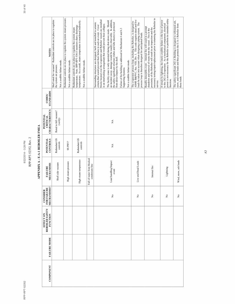
Mechanism 6 – Seismic Event
The 242-A Evaporator Reboiler and associated process loop piping is not required to perform its
safety function during or after a seismic event per HNF-14755, Documented Safety Analysis for
the 242-A Evaporator. However, the Reboiler and associated piping have been designed to
ASME code criteria. This requires the design to address loading due to seismic events.
A seismic event that would compromise the integrity of the Reboiler is a readily identifiable
event. Such an event will result in personal being evacuated from the condenser room and the
inspection of the Reboiler. Seismic activity will result in inspection and, if necessary, the
testing/repair/replacement prior to returning the Reboiler to service.
Mechanism 7 – Excessive Pressure from Process Air
During the control development meeting, a failure modes and effects analysis (FMEA) was
performed during which it was determined that this is not a credible failure mode. Redundant
mechanisms will prevent an over pressure failure of the 242-A Evaporator Reboiler.
Instrument and process air at 242-A is typically supplied by facility air compressors, but can also
be provided by portable air compressors. Each compressor has a dedicated pressure safety relief
valve. The pressure setting for the facility compressors is 155 psig while the portable
compressors have a 200 psig set pressure. Facility compressors fill the facility air receiver tank
R-E-1. The portable air compressors can be configured to bypass the receiver while still
supplying process or instrument air. From the R-E-1 receiver, air is reduced to either 3 psig
during process activities or 18 psig during times of inactivity (H-2-99001). To ensure air
pressure does not exceed the shell side pressure rating, PSV-EA1-3 is set at 25 psig.
Additionally, PSV-EA1-4, located on the steam supply line further protects the system with a set
pressure of 20 psig. Although this valve is located on the steam supply line, it is still a
significant component in mitigating over-pressurization of the Reboiler. The process air line is
directly connected to the steam line and cannot be isolated from PSV-EA1-4. These features
provide reasonable assurance that the Reboiler shell will not be over pressurized.
Mechanism 8 – Excessive Temperature from Air
During the control development meeting, a failure modes and effects analysis (FMEA) was
performed during which it was determined that this is not a credible failure mode. Redundant
RPP-RPT-52352 8/22/2014 - 3:28 PM 20 of 40

RPP-RPT-52352, Rev. 2
12
mechanisms will prevent a failure of the 242-A Evaporator Reboiler due to excessive
temperatures.
As previously indicated, instrument and process air at 242-A is typically supplied by facility air
compressors, but can also be provided by a portable compressor. The maximum discharge
temperature of facility compressors is 230°F (Email from manufacturer – Appendix D). The
maximum discharge temperature for a portable compressor (375 cfm unit) is approximately
248°F (Vendor literature). Upon reaching these maximum discharge temperatures, the
respective compressor will shut down. Neither of these maximum discharge temperatures
approach the Reboiler’s maximum design temperature of 350°F. This alone demonstrates that
the Reboiler’s design temperature cannot be surpassed by compressed air alone. Additionally,
the facility air compressors employ a number of safety features that prevent excessive air
temperatures. The first safety feature that would trigger a shutdown of the compressor is the
high oil temperature indication. The second safety feature is the high discharge temperature
switch. As stated above, if the discharge temperature exceeds 230F, the compressor will shut
down. Third is the high unit temperature switch. The compressor is designed for an operating
range of 40 to 115F. If the compressor, as a unit, exceeds the high temperature then the
compressor will shut down. Lastly, if the temperature increase for a given time interval is too
great, then the compressor will shut down.
Similarly, the portable compressors also have multiple safety features that prevent excessive air
temperatures. These compressors include features such as a maximum oil temperature switch
and a maximum discharge temperature switch. Additionally, discharge air is routed to receiver
tank R-E-1 using rubber air hoses typically rated for temperatures of 190°F or 220°F. Hose
integrity will be compromised before the Reboiler’s design temperature of 350°F is reached. Air
must then travel through several feet of small (typically 3/4”) un-insulated air-line. Due to air’s
low heat capacity, air flowing from the compressor discharge through the small process air
piping would experience significant heat loss and greatly reduce air temperature. These features
provide reasonable assurance that the shell will not exceed its design temperature rating.
Lastly, steam exits the Reboiler as condensate through steam traps arranged in parallel. The
functionality of the steam traps dispenses of accumulated condensate but prevents air from
flowing through them – thus, air can only pressurize the boiler. As such, air cannot be used as a
transport mechanism to convey heat to the Reboiler.
Mechanism 9 – Collapse of the Steam Column Generating a Vacuum on the Shell Side
During the control development meeting, a failure modes and effects analysis (FMEA) was
performed during which it was determined that this is not a credible failure mode. Redundant
features will prevent a vacuum from forming on the shell side of the Reboiler in the event of a
steam column collapse. During inactivity, air is delivered to the Reboiler via a pressure control
loop in which valve 5-10 is normally closed and valves 5-5 and 5-7 are normally open. When
steam flow is isolated from the Reboiler, solenoid valve HV-EA1-3 opens and 18 psig air is
provided to the Reboiler shell. When process activities are ongoing, and steam is supplied to the
Reboiler, solenoid valve HV-EA1-3 closes to isolate the air to the Reboiler. Further preventing a
vacuum condition in the Reboiler are two vacuum breakers installed in the process air supply
line. The first vacuum break, PSV1, is set to crack at -0.05 psig. The second vacuum break,
RPP-RPT-52352 8/22/2014 - 3:28 PM 21 of 40
RPP-RPT-52352, Rev. 2
13
PSV2, has a cracking pressure of -1.0 psig. Combined, these features provide reasonable
assurance that the shell will not be exposed to negative pressures.
Mechanism 10 – Excessive Pressure from Steam
During the control development meeting, a failure modes and effects analysis (FMEA) was
performed during which it was determined that this is not a credible failure mode. Redundant
features will prevent the over pressurization of the Reboiler by the steam system. Steam is
supplied to the Reboiler shell by a pair of packaged boiler units providing saturated steam at a set
pressure of 11-12 psig during normal operation. Each boiler is protected by a pressure safety
valve with a set of 15 psig. Inside of the Evaporator facility, PSV-EA1-2 has a set pressure of 20
psig. Further downstream of this pressure relief valve is another, PSV-EA1-4 also with a set
pressure of 20 psig. Additionally, the steam supply boilers are rated at 15 psig. With a Reboiler
design pressure rating of 100 psig, it is likely that the boilers will experience failure before the
Reboiler. Combined, these features provide reasonable assurance that the shell will not be under
negative pressures.
Mechanism 11 – Excessive Temperature from Steam
During the FMEA it was determined that this is not a credible failure mode. Redundant features
will prevent the steam from generating excessive temperatures in the Reboiler. The maximum
shell side design temperature of the E-A-1 Reboiler is 350°F. Saturated steam at 350°F
coincides with 119.9 psig. As described above, it is expected that the steam boilers will reach
the limits of their 15 psig pressure rating before the 100 psig Reboiler design pressure is reached.
This fact alone ensures that Reboiler will not be exposed to excessive temperatures. However,
each boiler draws upon three safety relief valves to regulate steam pressure. As identified
previously, the first PSV is located on the boiler in the JCI Annex with a 15 psig set pressure.
The other two, PSV-EA1-2 and PSV-EA1-4 (H-2-98992), are located in the Evaporator facility..
PSV-EA1-2 and PSV-EA1-4 each have set pressures of 20 psig. At 20 psig, the temperature of
saturated steam is 258.74°F significantly less than the design temperature of the Reboiler shell.
Combined, these features provide reasonable assurance that the shell will not be under negative
pressures.
Mechanism 12 – Structural Failure due to Excessive Weight: Back-Up of Condensate Line
Structural failure of the Reboiler due to excessive weight, i.e. condensate filling the vessel is
very unlikely. The condensate system incorporates three steam traps. Prior to start-up these
traps are verified to be in proper working order. During start-up, a significant amount of
condensation is formed which requires two of the three steam traps to be functioning. Once the
Reboiler is at operating temperature, only one steam trap is required to dispense with forming
condensate. During these operations (start-up and normal operation) there is at least one back-up
steam trap that can be utilized.
The original design calculations conducted by Struthers-Wells sized the support structure
considering the effects of the Evaporator vessel loading, Reboiler vessel loading, as well as,
seismic and temperature effects. The combined loadings resulted in the minimum required beam
size of W12x27 and W18x45 structural members to support the Reboiler. The seismic analysis
RPP-RPT-52352 8/22/2014 - 3:28 PM 22 of 40

RPP-RPT-52352, Rev. 2
14
consisted of a 0.28 g vertical seismic response spectra that was applied to the static design load
of 27 kips. The resulting seismic load equates to approximately 34.5 kips. Considering the
effect of condensate filling the Reboiler, the loading condition closely matches the seismic
design load (within 10%) for which the W12x27 and W18x45 beams were prescribed. Given the
structural members selected for the design loading, there is sufficient confidence that the higher
capacity W12x40 and W18x50 members used during construction(H-2-69280 and H-2-69285)
will support the bearing load of the Reboiler when full of slurry and steam condensate.
Bolted connections were designed in accordance with AISC 7th
ed., Table 1 (H-2-69281). Table
1 shows that the weakest connection used during construction of the Reboiler support structure is
acceptable for 15 ksi in shear or 21 ksi in bearing load: an equivalent Reboiler weight of
approximately 48 kips.
Given the structural members used in the design calculations and the structural members used in
construction, the support structure is sufficient for the bearing load of the Reboiler when full of
1.6 SpG slurry and steam condensate.
6.2.4 Other Failure Modes
No other unsafe failure modes of the Reboiler were identified during the FMEA evaluations.
6.2.5 Failure Modes and Mechanisms of Sample Analysis
Because sample analysis will be used to support qualification of the Reboiler, a safety related
structure, the sample analysis will be defined as a safety related function as well. This service
must be performed by a supplier with an evaluated NQA-1 program or a current International
Laboratory Accreditation Cooperation (ILAC) accreditation and listed on the Evaluated
Suppliers List (ESL). ILAC signatories include (but not limited to) the following:
a. The American Association for Laboratory Accreditation (A2LA)
b. National Voluntary Laboratory Accreditation Program (NVLAP)
c. International Accreditation Service, Inc. (IAS)
d. ANSI-ASQ National Accreditation Board (ACLASS)
e. Perry Johnson Laboratory Accreditation, Inc. (PJLA)
f. Accreditation Services Bureau (A-S-B)
g. American Industrial Hygiene Association Laboratory Accreditation Program (AIHA-
LAP).
Alternatively, the service supplier may be dedicated using TFC-ENG-DESIGN-C-15 which
would require a survey or source verification. To determine the potential failure modes and
failure mechanisms of sample analysis in the laboratory, a Failure Modes and Effects Analysis
(FMEA) was performed, evaluating which analytical failures led to a failure of the Reboiler’s
ability to perform its safety function, as stated in Section 4.0. Failure modes and failure
mechanisms of this service were identified. Necessary critical characteristics and controls were
then applied to safety-significant analysis of leak test samples.
RPP-RPT-52352 8/22/2014 - 3:28 PM 23 of 40

RPP-RPT-52352, Rev. 2
15
The discussion of the failure modes, as well as the effect of that failure mode on the safety
function of the system, is shown in Table 6-2, below:
Table 6-2. Failure Modes of the E-A-1 Reboiler
Component Failure Mode
Effect on Reboiler Tube and
Tubesheet Integrity Safety Function
QA Program
High Bias Results None
Low Bias Results False indication of sound Tubes and Tubesheets
Failure mechanisms for the failure mode “Low Bias Results” are identified in Table A-2. In
response to these failure mechanisms, Controls and Critical Characteristics were identified to
mitigate erroneous data.
6.2.6 Aging
The Evaporator Reboiler is fabricated from 304L Stainless Steel. As such, any degradation due
to time based aging is academic. 304L is unaffected by natural phenomena such as ambient
temperature swings. Damaging effects are brought about by erosion/corrosion through service
applications (see Mechanisms 1 and 2 above).
6.3 SUPPORTING SYSTEMS
The 242-A Building is designated safety-significant to prevent its failure due to ash, snow and
wind loads and, therefore, protect the E-A-1 Reboiler from damage due to these loads. The 242-
A Evaporator Facility structure offers protection from many natural phenomena hazards and off
normal accident scenario conditions. Additionally, this facility acts as a supporting structure for
the process circulation loop. Should a failure of the building structure occur, this would
obviously be detrimental to the integrity of the evaporation process loop and the Reboiler. This
facility, however, was designed for a 0.25 g horizontal seismic load. With the added
conservatism built into this calculation, this structure is designed to the equivalent of a PC-2
structure (RPP-RPT-52517, 242-A Evaporator Facility Assessment for Performance Category 2
Natural Phenomena Hazards).
7.0 CONTROLS
Controls necessary to protect the E-A-1 Reboiler vessel were identified during the FMEA
process, as outlined in sections 6.2.1 thru 6.2.5. The controls recommended for these systems
are carried forward and summarized in this section. If any of these controls cannot be met in the
design and installation phase, then this document must be revised to identify new controls.
RPP-RPT-52352 8/22/2014 - 3:28 PM 24 of 40
RPP-RPT-52352, Rev. 2
16
7.1 CONTROLS
To assess the integrity of the tube bundle, a liquid dye leak test will be performed every five
years (see Section 6.1). Documentation showing how this control is to be fulfilled is presented in
Appendix C
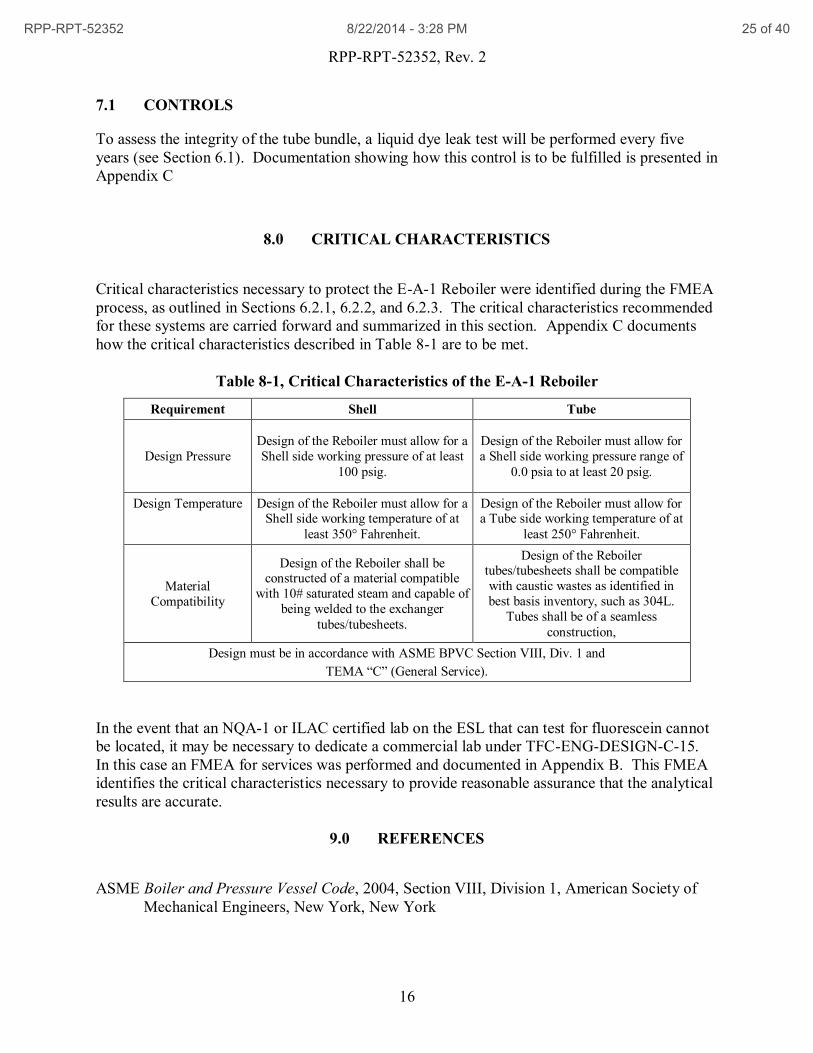
8.0 CRITICAL CHARACTERISTICS
Critical characteristics necessary to protect the E-A-1 Reboiler were identified during the FMEA
process, as outlined in Sections 6.2.1, 6.2.2, and 6.2.3. The critical characteristics recommended
for these systems are carried forward and summarized in this section. Appendix C documents
how the critical characteristics described in Table 8-1 are to be met.
Table 8-1, Critical Characteristics of the E-A-1 Reboiler
Requirement Shell Tube
Design Pressure
Design of the Reboiler must allow for a
Shell side working pressure of at least
100 psig.
Design of the Reboiler must allow for
a Shell side working pressure range of
0.0 psia to at least 20 psig.
Design Temperature Design of the Reboiler must allow for a Shell side working temperature of at
least 350° Fahrenheit.
Design of the Reboiler must allow for a Tube side working temperature of at
least 250° Fahrenheit.
Material
Compatibility
Design of the Reboiler shall be constructed of a material compatible
with 10# saturated steam and capable of
being welded to the exchanger
tubes/tubesheets.
Design of the Reboiler tubes/tubesheets shall be compatible
with caustic wastes as identified in
best basis inventory, such as 304L.
Tubes shall be of a seamless
construction,
Design must be in accordance with ASME BPVC Section VIII, Div. 1 and
TEMA “C” (General Service).
In the event that an NQA-1 or ILAC certified lab on the ESL that can test for fluorescein cannot
be located, it may be necessary to dedicate a commercial lab under TFC-ENG-DESIGN-C-15.
In this case an FMEA for services was performed and documented in Appendix B. This FMEA
identifies the critical characteristics necessary to provide reasonable assurance that the analytical
results are accurate.
9.0 REFERENCES
ASME Boiler and Pressure Vessel Code, 2004, Section VIII, Division 1, American Society of
Mechanical Engineers, New York, New York
RPP-RPT-52352 8/22/2014 - 3:28 PM 25 of 40
RPP-RPT-52352, Rev. 2
17
ASME B16.5, 2009, ASME B16.5 Pipe Flanges and Flanged Fittings, American Society of
Mechanical Engineers, New York, New York.
ASME B31.1, 2001, ASME B31.1, Power Piping, American Society of Mechanical Engineers,
New York, New York.
ASME B31.1a, 2002, Addenda to ASME B31.1-2001, Power Piping, American Society of
Mechanical Engineers, New York, New York.
ASME B31.3, Section VIII, 2002, Process Piping, American Society of Mechanical Engineers,
New York, New York.
CVI-20253, Certified Vendor Information for the 242-A Vacuum Evaporator Crystallizer, 1977,
Washington River Protection Solutions, Richland, Washington.
ECN-11-002072, 242-A Evaporator Reboiler Condensate System Upgrade, 2012, Washington
River Protection Solutions, Richland, Washington.
H-2-69280, Sht. 1, Structural Second Floor Plan Sections & Details Areas 1 & 2, Rev. 1,
Washington River Protection Solutions, Richland, Washington.
H-2-69281, Sht. 1, Structural Plans, Platforms Sections & Details Areas 1 & 2, Rev. 1,
Washington River Protection Solutions, Richland, Washington.
H-2-69285, Sht. 1, Structural Sections & Details Areas 1 & 2, Rev. 1, Washington River
Protection Solutions, Richland, Washington.
H-2-98988, Sht. 2, P&ID Evaporator Recirculation System, Rev. 16, Washington River
Protection Solutions, Richland, Washington.
H-2-98992, Sht. 1, P&ID Steam System, Rev. 35, Washington River Protection Solutions,
Richland, Washington.
H-2-98993, Sht. 1, P&ID Steam Condensate System, Rev. 31, Washington River Protection
Solutions, Richland, Washington.
H-2-98995, Sht. 2, P&ID Drain System, Rev. 11, Washington River Protection Solutions,
Richland, Washington.
H-2-99001, Sht. 1, P&ID Process & Instrument Air System, Rev. 26, Washington River
Protection Solutions, Richland, Washington.
H-2-99001, Sht. 2, P&ID Process & Instrument Air System, Rev. 13, Washington River
Protection Solutions, Richland, Washington.
RPP-RPT-52352 8/22/2014 - 3:28 PM 26 of 40

RPP-RPT-52352, Rev. 2
18
HAP-655, (1971) Calculation A-10 Evaporator Support, U.S. Atomic Energy Commission,
Richland, Washington.
NiDI Technical Series No. 10 019, 1988, Alloy Selection for Caustic Soda Service, Nickel
Development Institute, Toronto, Canada.
RPP-48900, 242-A Evaporator Hazard Evaluation Database Report, as amended, Washington
River Protection Solutions, Richland, Washington.
RPP-CALC-48552, 2011, Jumper Assembly C to 4-40 and 4 to 5/40 to 21 Calculation Package,
Rev. 2, Washington River Protection Solutions, Richland, Washington.
RPP-CALC-57003, 2014, Fluorescein Tracer Test Analysis, Rev. 0, Washington River
Protection Solutions, Richland, Washington.
RPP-RPT-41041, Technical Evaluation of the 242-A Evaporator Facility Steam and Steam
Condensate System, Rev. 0, Washington River Protection Solutions, Richland,
Washington.
RPP-RPT-52517, 242-A Evaporator Facility Assessment for Performance Category 2 Natural
Phenomena Hazards, Rev. 0, Washington River Protection Solutions, Richland,
Washington.
RPP-RPT-58179, Evaluation of Halide Stress Corrosion Cracking and Pitting in the 242-A E-A-
1 Reboiler as it Related to Operating Parameters and Tank Waste Chemistry, Rev. 0,
Washington River Protection Solutions, Richland, Washington.
RPP-TE-54842, 242-A Evaporator E-A-1 Reboiler Upgrade to Safety Significant QL-2, Rev. 0,
Washington River Protection Solutions, Richland, Washington.
TFC-ENG-FACSUP-C-23, 2010, Control Development Process for Safety-Significant
Structures, Systems, and Components, Rev. D-4, Washington River Protection Solutions,
Richland, Washington.
TFC-ENG-STD-34, 2011, Standard for the Selection of Non-Metallic Materials in Contact with
Tank Waste, Rev. A, Washington River Protection Solutions, Richland, Washington.
RPP-RPT-52352 8/22/2014 - 3:28 PM 27 of 40
RPP-RPT-52352, Rev. 2
A1
APPENDIX A
E-A-1 REBOILER FMEA
RPP-RPT-52352 8/22/2014 - 3:28 PM 28 of 40
RP
P-R
PT
-52
35
2,
Rev
. 2
A2
AP
PE
ND
IX A
- E
-A-1
RE
BO
ILE
R F
ME
A
CO
MP
ON
EN
T
FA
ILU
RE
MO
DE
EF
FE
CT
ON
RE
BO
ILE
R S
AF
ET
Y
FU
NC
TIO
N
CO
NS
IDE
R
FO
R F
AIL
UR
E
ME
CH
AN
ISM
S?
FA
ILU
RE
ME
CH
AN
ISM
S
PO
TE
NT
IAL
CO
NT
RO
LS
PO
TE
NT
IAL
CR
ITIC
AL
CH
AR
AC
TE
RIS
TIC
S
CO
DE
S/
ST
AN
DA
RD
S
NO
TE
S
Reb
oil
er T
ubes
an
d T
ube
shee
ts
Lea
k
Loss
of
inte
gri
ty
Yes
E
rosi
on
Fu
nct
ion
al T
est
(Flu
ore
scei
n D
ye
test
), I
QR
PE
eval
uat
ion
Mat
eria
l se
lect
ion
, T
hic
kn
ess,
Cor
rect
wel
din
g p
roce
ss
AS
ME
B&
PV
C,
Sec
. V
III,
Div
. 1,
TE
MA
C
Curr
ent
Reb
oil
er f
abri
cate
d f
rom
SA
-240
Typ
e 3
04
L,
SA
-213
Typ
e
30
4L
.
Hal
ide
Ind
uce
d S
tres
s
Corr
osi
on
Cra
ckin
g
Fu
nct
ion
al T
est
(Flu
ore
scei
n D
ye
test
), I
QR
PE
eval
uat
ion
Mat
eria
l S
elec
tion
, T
hic
kn
ess,
Cor
rect
wel
din
g p
roce
ss
AS
ME
B&
PV
C,
Sec
. V
III,
Div
. 1,
TE
MA
C
Was
te t
emp
erat
ure
s an
d t
he
pre
sen
ce o
f h
alid
es c
reat
e th
e p
oten
tial
for
hal
ide
ind
uce
d s
tres
s co
rrosi
on
cra
ckin
g. H
ow
ever
, th
e R
eboil
er
does
not
exp
erie
nce
th
e st
ress
es n
eces
sary
to c
reat
e a
cata
stro
ph
ic
fail
ure
. L
eak
rat
es t
hro
ugh
str
ess
crac
ks
are
ver
y s
mal
l d
ue
to t
he
ver
y sm
all
thic
kn
ess
of
the
crac
ks.
Lea
ks
are
not
of
suff
icie
nt
mag
nit
ud
e to
res
ult
in
a s
ign
ific
ant
faci
lity
work
er h
azar
d o
ver
th
e
fun
ctio
nal
tes
t fr
equ
ency
.
Man
agin
g w
aste
ch
emis
try
to a
llow
for
suff
icie
nt
Nit
rate
s an
d
Hyd
rox
ides
wil
l m
inim
ize
hal
ide
ind
uce
d c
orr
osi
on
.
H
alid
e In
du
ced
Corr
osi
on
Pit
tin
g
Fu
nct
ion
al T
est
(Flu
ore
scei
n D
ye
test
), I
QR
PE
eval
uat
ion
Mat
eria
l S
elec
tion
, T
hic
kn
ess,
Cor
rect
wel
din
g p
roce
ss
AS
ME
B&
PV
C,
Sec
. V
III,
Div
. 1,
TE
MA
C
Corr
osi
on
pit
tin
g h
as t
he
pote
nti
al t
o c
reat
e lo
cali
zed
are
as o
f th
rou
gh
wal
l p
enet
rati
on
s (v
ery
smal
l le
aks)
. A
lth
ou
gh
th
is i
s an
aggre
ssiv
e
fail
ure
mec
han
ism
, it
is
lim
ited
to u
nd
er d
eposi
ts a
nd
cre
vic
es a
nd
man
ifes
ts i
tsel
f as
dri
p w
ise
leak
age
or
wee
pin
g.
Lea
ks
are
not
of
suff
icie
nt
mag
nit
ud
e to
res
ult
in
a s
ign
ific
ant
faci
lity
work
er h
azar
d
over
th
e fu
nct
ion
al t
est
freq
uen
cy.
Con
du
ctin
g a
dee
p f
lush
of
the
C-A
-1 v
esse
l an
d r
ecir
cula
tion
loop
afte
r p
ot
has
bee
n e
mp
tied
of
was
te w
ill
min
imiz
e p
itti
ng
corr
osi
on
.
F
atig
ue
(th
erm
al c
ycl
e):
Am
bie
nt
to 2
50°F
N
on
e
Mat
eria
l se
lect
ion
,
Des
ign
par
amet
er,
Corr
ect
wel
din
g p
roce
ss
AS
ME
B&
PV
C,
Sec
. V
III,
Div
. 1,
TE
MA
C
90
# t
o 1
0#
cro
sso
ver
ou
tsid
e th
e ev
apora
tion
mu
st b
e re
moved
to
lim
it m
ax t
emp
erat
ure
Tra
nsi
ent
pre
ssure
even
t
(ste
am/c
on
den
sate
sid
e)
Mai
nta
in a
ll 3
ste
am
trap
s op
en
NA
A
SM
E B
31
.1
New
des
ign
of
con
den
sate
wil
l pre
ven
t w
ater
ham
mer
.
Rec
om
men
ded
as
Op
erat
ion
al C
on
trol,
not
as a
Saf
ety
Con
trol.
Mec
han
ical
fat
igu
e
(vib
rati
on)
Fu
nct
ion
al T
est
(Flu
ore
scei
n D
ye
test
), I
QR
PE
eval
uat
ion
Mat
eria
l se
lect
ion
, T
hic
kn
ess,
Des
ign
Cal
cula
tion
AS
ME
B&
PV
C,
Sec
. V
III,
Div
. 1,
TE
MA
C
yea
rs o
f op
erat
ion
wit
hou
t fa
ilure
s/n
oti
ceab
le v
ibra
tion
S
eism
ic e
ven
t N
on
e P
revio
usl
y se
ism
ical
ly
qu
alif
ied
des
ign
AS
ME
B&
PV
C,
Sec
. V
III,
Div
. 1,
TE
MA
C
Th
e E
-A-1
Reb
oil
er m
ay n
ot
per
form
its
saf
ety
fun
ctio
n d
uri
ng o
r
afte
r a
seis
mic
even
t.
Sei
smic
eval
uat
ion
of
Reb
oil
er a
nd
28”
reci
rcu
lati
on
pip
ing:
RP
P-
RP
T-5
25
17
, 2
42
-A E
vap
orat
or
Fac
ilit
y A
sses
smen
t fo
r P
erfo
rman
ce
Cat
egory
2 N
atura
l P
hen
om
ena
Haz
ard
s.
H
igh
air
pre
ssure
S
S P
RV
?
Red
un
dan
t co
ntr
ols
are
in
pla
ce t
o r
egula
te t
he
syst
em a
ir p
ress
ure
.
Not
a cr
edib
le f
ailu
re m
od
e.
H
igh
air
tem
per
ature
R
edu
nd
ant
GS
con
trols
Red
un
dan
t co
ntr
ols
are
in
pla
ce t
o r
egula
te t
he
syst
em a
ir
tem
per
ature
.
Not
a cr
edib
le f
ailu
re m
od
e.
RP
P-R
PT
-52352
8/2
2/2
014 -
3:2
8 P
M29 o
f 40
RP
P-R
PT
-52
35
2,
Rev
. 2
A3
AP
PE
ND
IX A
- E
-A-1
RE
BO
ILE
R F
ME
A
CO
MP
ON
EN
T
FA
ILU
RE
MO
DE
EF
FE
CT
ON
RE
BO
ILE
R S
AF
ET
Y
FU
NC
TIO
N
CO
NS
IDE
R
FO
R F
AIL
UR
E
ME
CH
AN
ISM
S?
FA
ILU
RE
ME
CH
AN
ISM
S
PO
TE
NT
IAL
CO
NT
RO
LS
PO
TE
NT
IAL
CR
ITIC
AL
CH
AR
AC
TE
RIS
TIC
S
CO
DE
S/
ST
AN
DA
RD
S
NO
TE
S
S
hel
l si
de
vac
uum
R
edu
nd
ant
GS
con
trols
Rat
ed t
o f
ull
vac
uu
m?
(ver
ify)
Sh
ell
rate
d f
or
vac
uu
m?
Red
un
dan
t co
ntr
ols
are
in
pla
ce t
o r
egu
late
the
syst
em a
ir p
ress
ure
.
Not
a cr
edib
le f
ailu
re m
od
e.
H
igh
ste
am p
ress
ure
S
S P
RV
?
Red
un
dan
t co
ntr
ols
are
in
pla
ce t
o r
egula
te t
he
syst
em s
team
pre
ssure
.
Not
a cr
edib
le f
ailu
re m
od
e.
H
igh
ste
am t
emp
erat
ure
R
edu
nd
ant
GS
con
trols
Red
un
dan
t co
ntr
ols
are
in
pla
ce t
o r
egula
te t
he
syst
em s
team
tem
per
ature
. N
ote
: R
PP
-RP
T-5
36
13
mon
itors
slu
rry
dis
char
ge
tem
per
ature
. A
s a
resu
lt, st
eam
tem
per
ature
is
mon
itor
ed i
ndir
ectl
y.
Not
a cr
edib
le f
ailu
re m
od
e.
Fu
ll o
f w
ater
fro
m b
lock
ed
con
den
sate
lin
e
No
L
oad
han
dli
ng/I
mp
act
even
t N
A
NA
Su
rroun
din
g s
tru
cture
s ar
e d
esig
ned
, bu
ilt
and
in
stal
led
to s
eism
ic
crit
eria
th
at w
ou
ld p
reven
t th
eir
fail
ure
in
su
ch a
n e
ven
t.
Cov
er
blo
cks
loca
ted
over
th
e ev
apora
tor
and
Reb
oil
er v
esse
ls a
re i
nst
alle
d
in a
n i
nte
rlock
ing a
rran
gem
ent
that
wou
ld p
reven
t th
eir
coll
apse
.
Th
e fa
cili
ty c
ran
e is
on
ly o
per
ated
duri
ng
sh
ut-
dow
n m
od
e. S
hou
ld
an i
nci
den
t occ
ur,
dam
age
wou
ld b
e re
adil
y obse
rvab
le.
In
ad
dit
ion
,
the
safe
ty s
ign
ific
ant
stru
cture
(tu
bes
an
d t
ube
shee
ts)
is p
rote
cted
fr
om
dir
ect
imp
act
by
the
shel
l.
Fai
lure
of
the
bu
ild
ing i
s ad
dre
ssed
in
Mec
han
ism
6 a
nd 6
.3
Sup
port
ing
Sys
tem
s.
Not
a cr
edib
le f
ailu
re m
od
e.
No
L
ive
and D
ead
Load
s
Th
e ev
apora
tor
pro
cess
loop
, in
clu
din
g t
he
Reb
oil
er, is
des
ign
ed t
o
AS
ME
B&
PV
C,
Sec
. V
III,
Div
. 1. T
his
cod
e re
quir
es d
ead a
nd l
ive
load
s be
tak
en i
nto
acc
ou
nt
wh
en d
esig
nin
g a
pip
ing
sys
tem
. T
he
pro
cess
lo
op
is
ther
efore
des
ign
ed f
or
anti
cipat
ed l
oad
s.
No
In
tern
al f
ire
Rea
dil
y d
etec
table
even
t – I
nte
rnal
fir
e w
ill
resu
lt i
n a
pro
mpt
shutd
ow
n a
nd r
emoval
of
was
te f
rom
th
e ves
sel.
F
ire
in t
he
pro
xim
ity
of
the
Reb
oil
er w
ill
resu
lt i
n a
n i
nsp
ecti
on
an
d t
he
nec
essa
ry t
esti
ng
/rep
air/
repla
cem
ent
pri
or
to r
eturn
ing t
he
Reb
oil
er t
o
serv
ice.
No
L
igh
tnin
g
If s
tru
ck b
y li
gh
tnin
g, th
e lo
nel
y cr
edib
le f
ailu
re i
s th
e lo
ss o
f p
ow
er
to t
he
24
2-A
Evap
ora
tor.
A
s a
mec
han
ical
com
pon
ent,
ele
ctri
cal
po
wer
is
not
nec
essa
ry f
or
the
Reb
oil
er t
o p
erfo
rm i
ts i
nte
nd
ed s
afet
y
fun
ctio
n.
No
W
ind, sn
ow
, as
h l
oad
s
Th
e sa
fety
-sig
nif
ican
t 24
2-A
Bu
ild
ing
is
des
ign
ed t
o w
ith
stan
d a
sh,
snow
, an
d w
ind l
oad
s an
d t
hu
s pro
tect
s th
e E
-A-1
Reb
oil
er f
rom
thes
e lo
ads.
RP
P-R
PT
-52352
8/2
2/2
014 -
3:2
8 P
M30 o
f 40

RP
P-R
PT
-52
35
2,
Rev
. 2
A4
AP
PE
ND
IX A
- E
-A-1
RE
BO
ILE
R F
ME
A
CO
MP
ON
EN
T
FA
ILU
RE
MO
DE
EF
FE
CT
ON
RE
BO
ILE
R S
AF
ET
Y
FU
NC
TIO
N
CO
NS
IDE
R
FO
R F
AIL
UR
E
ME
CH
AN
ISM
S?
FA
ILU
RE
ME
CH
AN
ISM
S
PO
TE
NT
IAL
CO
NT
RO
LS
PO
TE
NT
IAL
CR
ITIC
AL
CH
AR
AC
TE
RIS
TIC
S
CO
DE
S/
ST
AN
DA
RD
S
NO
TE
S
No
E
xtr
eme
tem
per
ature
s
En
vir
onm
enta
l d
esig
n t
emp
erat
ure
req
uir
emen
ts a
re i
den
tifi
ed i
n
TF
C-E
NG
-ST
D-0
2, E
nvir
on
men
tal/
Sea
son
al R
equ
irem
ents
for
TO
C
Sys
tem
s, S
tru
cture
s, a
nd C
om
pon
ents
. T
his
sta
nd
ard i
den
tifi
es a
des
ign
tem
per
ature
of
-25
° to
11
5°F
for
SS
C’s
th
at a
re e
xp
ose
d t
o
ou
tdo
or
ambie
nt
con
dit
ion
s.
It i
s ex
pec
ted
th
at t
emp
erat
ure
s w
ith
in
the
faci
lity
wil
l n
ot
exce
ed o
utd
oor
con
dit
ion
s.
Hig
h e
nvir
on
men
tal
tem
per
ature
s ar
e bou
nd
ed b
y p
roce
ss
tem
per
ature
s. F
ailu
re d
ue
to l
ow
tem
per
ature
s (<
32
°F)
or
free
zin
g i
s
not
a cr
edib
le f
ailu
re m
ech
anis
m d
uri
ng
Op
erat
ion
s M
od
e as
evap
ora
tor
op
erat
ion
s w
ou
ld b
e st
op
ped
pri
or
to r
each
ing
a f
reez
ing
con
dit
ion
wit
hin
th
e bu
ildin
g. D
amag
e w
hen
not
in O
per
atio
n M
od
e
wil
l re
sult
in
an
in
spec
tion
an
d t
he
nec
essa
ry
test
ing
/rep
air/
rep
lace
men
t pri
or t
o r
eturn
ing
th
e E
-A-1
Reb
oil
er t
o
serv
ice.
No
A
sh/d
ust
exp
osu
re
N
ot
a cr
edib
le f
ailu
re m
ech
anis
m.
No
L
oss
of
exte
rnal
pow
er
N
ot
a cr
edib
le f
ailu
re m
ech
anis
m.
No
E
xte
rnal
fir
e
Not
a cr
edib
le f
ailu
re m
ech
anis
m.
No
H
igh
dif
fere
nti
al p
ress
ure
ac
ross
Reb
oil
er
NA
N
A
R
equ
ires
plu
gg
ing o
f tu
bes
an
d m
ax h
ead o
f p
um
p. N
ot
a cr
edib
le
fail
ure
mod
e.
Plu
g
Non
e
RP
P-R
PT
-52352
8/2
2/2
014 -
3:2
8 P
M31 o
f 40

RPP-RPT-52352, Rev. 2
B1
APPENDIX B
LABORATORY SAMPLE ANALYSIS FMEA
RPP-RPT-52352 8/22/2014 - 3:28 PM 32 of 40
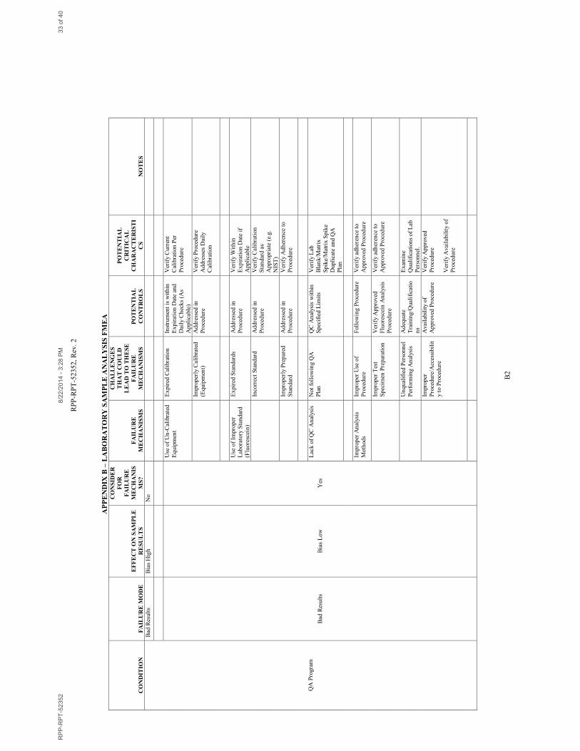
RP
P-R
PT
-52
35
2,
Rev
. 2
B2
AP
PE
ND
IX B
– L
AB
OR
AT
OR
Y S
AM
PL
E A
NA
LY
SIS
FM
EA
CO
ND
ITIO
N
FA
ILU
RE
MO
DE
EF
FE
CT
ON
SA
MP
LE
RE
SU
LT
S
CO
NS
IDE
R
FO
R
FA
ILU
RE
ME
CH
AN
IS
MS
?
FA
ILU
RE
ME
CH
AN
ISM
S
CH
AL
LE
NG
ES
TH
AT
CO
UL
D
LE
AD
TO
TH
ES
E
FA
ILU
RE
ME
CH
AN
ISM
S
PO
TE
NT
IAL
CO
NT
RO
LS
PO
TE
NT
IAL
CR
ITIC
AL
CH
AR
AC
TE
RIS
TI
CS
N
OT
ES
QA
Pro
gra
m
Bad
Res
ult
s B
ias
Hig
h
No
Bad
Res
ult
s B
ias
Lo
w
Yes
Use
of
Un
-Cal
ibra
ted
Eq
uip
men
t
Exp
ired
Cal
ibra
tion
In
stru
men
t is
wit
hin
Exp
irat
ion
Dat
e an
d
Dai
ly C
hec
ks
(As
Ap
pli
cable
)
Ver
ify
Cu
rren
t
Cal
ibra
tion
Per
Pro
ced
ure
Im
pro
per
ly C
alib
rate
d
(Eq
uip
men
t)
Ad
dre
ssed
in
Pro
ced
ure
Ver
ify
Pro
ced
ure
Ad
dre
sses
Dai
ly
Cal
ibra
tion
Use
of
Impro
per
Lab
ora
tory
Sta
nd
ard
(Flu
ore
scei
n)
Exp
ired
Sta
nd
ard
s A
dd
ress
ed i
n
Pro
ced
ure
Ver
ify
Wit
hin
Exp
irat
ion
Dat
e if
Ap
pli
cable
In
corr
ect
Sta
ndar
d
Ad
dre
ssed
in
Pro
ced
ure
Ver
ify
Cal
ibra
tion
Sta
ndar
d a
s A
pp
ropri
ate
(e.g
.
NIS
T)
Im
pro
per
ly P
rep
ared
Sta
ndar
d
Ad
dre
ssed
in
Pro
ced
ure
Ver
ify
Ad
her
ence
to
Pro
ced
ure
Lac
k o
f Q
C A
nal
ysis
N
ot
foll
ow
ing Q
A
Pla
n
QC
An
alys
is w
ith
in
Sp
ecif
ied
Lim
its
Ver
ify
Lab
Bla
nk/M
atri
x
Sp
ike/
Mat
rix S
pik
e
Dup
lica
te a
nd Q
A
Pla
n
Impro
per
An
alys
is
Met
hod
s
Impro
per
Use
of
Pro
ced
ure
Foll
ow
ing
Pro
ced
ure
V
erif
y ad
her
ence
to
Ap
pro
ved
Pro
ced
ure
Im
pro
per
Tes
t
Sp
ecim
en P
rep
arat
ion
Ver
ify
Ap
pro
ved
Flu
ore
scei
n A
nal
ysis
Pro
ced
ure
Ver
ify
adh
eren
ce t
o
Ap
pro
ved
Pro
ced
ure
U
nq
ual
ifie
d P
erso
nn
el
Per
form
ing A
nal
ysis
Ad
equ
ate
Tra
inin
g/Q
ual
ific
atio
ns
Ex
amin
e
Qu
alif
icat
ion
s of
Lab
Per
son
nel
.
Im
pro
per
Pro
ced
ure
/Acc
essi
bil
it
y to
Pro
ced
ure
Avai
labil
ity o
f
Ap
pro
ved
Pro
ced
ure
Ver
ify
Ap
pro
ved
Pro
ced
ure
Ver
ify
Avai
labil
ity
of
Pro
ced
ure
RP
P-R
PT
-52352
8/2
2/2
014 -
3:2
8 P
M33 o
f 40
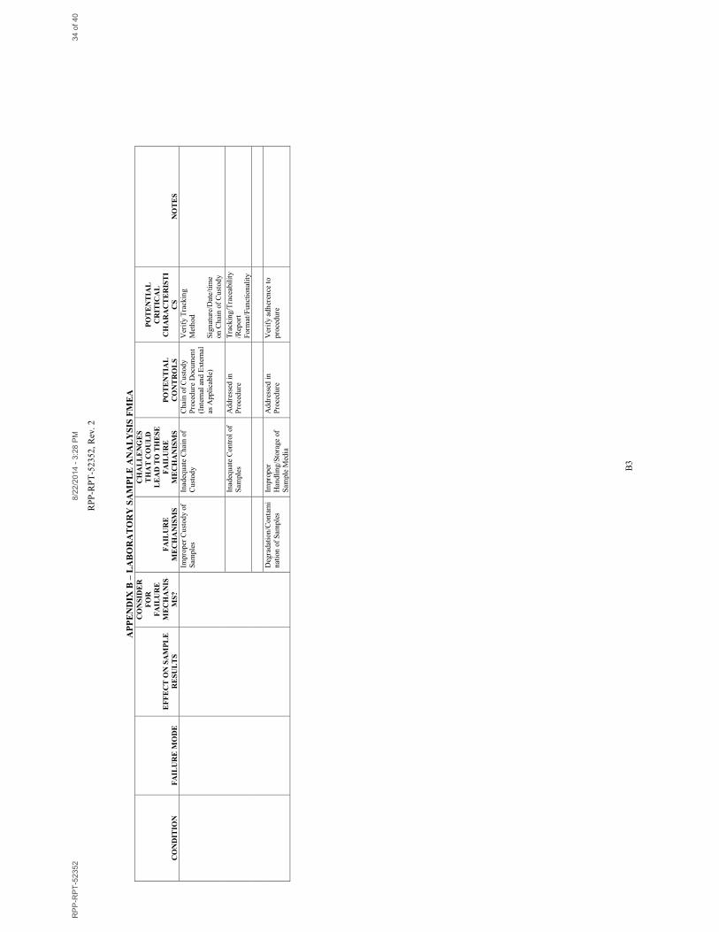
RP
P-R
PT
-52
35
2,
Rev
. 2
B3
AP
PE
ND
IX B
– L
AB
OR
AT
OR
Y S
AM
PL
E A
NA
LY
SIS
FM
EA
CO
ND
ITIO
N
FA
ILU
RE
MO
DE
EF
FE
CT
ON
SA
MP
LE
RE
SU
LT
S
CO
NS
IDE
R
FO
R
FA
ILU
RE
ME
CH
AN
IS
MS
?
FA
ILU
RE
ME
CH
AN
ISM
S
CH
AL
LE
NG
ES
TH
AT
CO
UL
D
LE
AD
TO
TH
ES
E
FA
ILU
RE
ME
CH
AN
ISM
S
PO
TE
NT
IAL
CO
NT
RO
LS
PO
TE
NT
IAL
CR
ITIC
AL
CH
AR
AC
TE
RIS
TI
CS
N
OT
ES
Impro
per
Cu
stod
y of
Sam
ple
s
Inad
equ
ate
Ch
ain
of
Cu
stod
y
Ch
ain
of
Cu
stod
y
Pro
ced
ure
Docu
men
t
(In
tern
al a
nd E
xte
rnal
as A
ppli
cable
)
Ver
ify
Tra
ckin
g
Met
hod
Sig
nat
ure
/Dat
e/ti
me
on
Ch
ain
of
Cu
stod
y
In
adeq
uat
e C
on
trol
of
Sam
ple
s
Ad
dre
ssed
in
Pro
ced
ure
Tra
ckin
g/T
race
abil
ity
/Rep
ort
Form
at/F
un
ctio
nal
ity
Deg
radat
ion
/Con
tam
i
nat
ion
of
Sam
ple
s
Impro
per
Han
dli
ng
/Sto
rag
e of
Sam
ple
Med
ia
Ad
dre
ssed
in
Pro
ced
ure
Ver
ify
adh
eren
ce t
o
pro
ced
ure
RP
P-R
PT
-52352
8/2
2/2
014 -
3:2
8 P
M34 o
f 40

RPP-RPT-52352, Rev. 2
C1
APPENDIX C
242-A EVAPORATOR E-A-1 REBOILER DESIGN REQUIREMENTS
RPP-RPT-52352 8/22/2014 - 3:28 PM 35 of 40
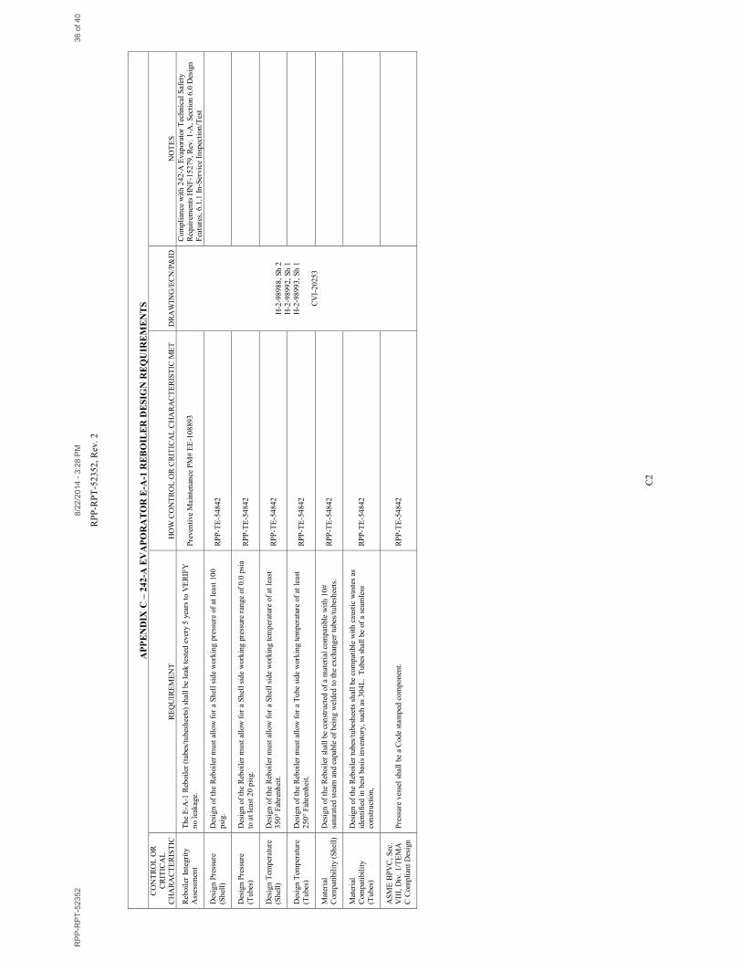
RP
P-R
PT
-52
35
2,
Rev
. 2
C2
AP
PE
ND
IX C
– 2
42
-A E
VA
PO
RA
TO
R E
-A-1
RE
BO
ILE
R D
ES
IGN
RE
QU
IRE
ME
NT
S
CO
NT
RO
L O
R
CR
ITIC
AL
CH
AR
AC
TE
RIS
TIC
R
EQ
UIR
EM
EN
T
HO
W C
ON
TR
OL
OR
CR
ITIC
AL
CH
AR
AC
TE
RIS
TIC
ME
T
DR
AW
ING
/EC
N/P
&ID
N
OT
ES
Reb
oil
er I
nte
gri
ty
Ass
essm
ent
Th
e E
-A-1
Reb
oil
er (
tubes
/tubes
hee
ts)
shal
l be
leak
tes
ted
ever
y 5
yea
rs t
o V
ER
IFY
no l
eak
age.
P
reven
tive
Mai
nte
nan
ce P
M#
EE
-10
889
3
H-2
-98
98
8,
Sh
2
H-2
-98
99
2,
Sh
1
H-2
-98
99
3,
Sh
1
CV
I-2
02
53
Com
pli
ance
wit
h 2
42-A
Evap
orat
or
Tec
hn
ical
Saf
ety
Req
uir
emen
ts H
NF
-15
27
9, R
ev.
1-A
, S
ecti
on
6.0
Des
ign
Fea
ture
s, 6
.1.1
In
-Ser
vic
e In
spec
tion
/Tes
t
Des
ign
Pre
ssu
re
(Sh
ell)
Des
ign
of
the
Reb
oil
er m
ust
all
ow
for
a S
hel
l si
de
work
ing
pre
ssure
of
at l
east
10
0
psi
g.
RP
P-T
E-5
48
42
Des
ign
Pre
ssu
re
(Tubes
)
Des
ign
of
the
Reb
oil
er m
ust
all
ow
for
a S
hel
l si
de
work
ing
pre
ssure
ran
ge
of
0.0
psi
a
to a
t le
ast
20 p
sig.
RP
P-T
E-5
48
42
Des
ign
Tem
per
ature
(S
hel
l)
Des
ign
of
the
Reb
oil
er m
ust
all
ow
for
a S
hel
l si
de
work
ing
tem
per
ature
of
at l
east
3
50
° F
ahre
nh
eit.
R
PP
-TE
-54
84
2
Des
ign
Tem
per
ature
(Tubes
)
Des
ign
of
the
Reb
oil
er m
ust
all
ow
for
a T
ube
sid
e w
ork
ing
tem
per
ature
of
at l
east
25
0°
Fah
ren
hei
t.
RP
P-T
E-5
48
42
Mat
eria
l
Com
pat
ibil
ity
(Sh
ell)
Des
ign
of
the
Reb
oil
er s
hal
l be
con
stru
cted
of
a m
ater
ial
com
pat
ible
wit
h 1
0#
satu
rate
d s
team
an
d c
apab
le o
f b
ein
g w
eld
ed t
o t
he
exch
ang
er t
ubes
/tubes
hee
ts.
RP
P-T
E-5
48
42
Mat
eria
l
Com
pat
ibil
ity
(Tubes
)
Des
ign
of
the
Reb
oil
er t
ubes
/tubes
hee
ts s
hal
l be
com
pat
ible
wit
h c
aust
ic w
aste
s as
iden
tifi
ed i
n b
est
bas
is i
nven
tory
, su
ch a
s 3
04
L. T
ubes
sh
all be
of
a se
amle
ss
con
stru
ctio
n,
RP
P-T
E-5
48
42
AS
ME
BP
VC
, S
ec.
VII
I, D
iv.
1/T
EM
A
C C
om
pli
ant
Des
ign
Pre
ssu
re v
esse
l sh
all
be
a C
od
e st
amp
ed c
om
pon
ent.
R
PP
-TE
-54
84
2
RP
P-R
PT
-52352
8/2
2/2
014 -
3:2
8 P
M36 o
f 40
RPP-RPT-52352, Rev. 2
D1
APPENDIX D
E-MAIL STATEMENT OF MAXIMUM DISCHARGE TEMPERATURE
RPP-RPT-52352 8/22/2014 - 3:28 PM 37 of 40

RPP-RPT-52352, Rev. 2
D2
RPP-RPT-52352 8/22/2014 - 3:28 PM 38 of 40
RPP-RPT-52352, Rev. 2
D3
RPP-RPT-52352 8/22/2014 - 3:28 PM 39 of 40
RPP-RPT-52352, Rev. 2
D4
RPP-RPT-52352 8/22/2014 - 3:28 PM 40 of 40