rsc-364 development kit manual - amobbsd1.amobbs.com/bbs_upload782111/files_11/ourdev_51… · ·...
TRANSCRIPT
RSC-364 Development Kit Manualwith Sensory Speech 6 Technology
P/N: 60-0189-1

table of contents
Chapter 1 - OverviewIntroduction . . . . . . . . . . . . . . . . . . . . . . . . . . . . . . . . . . . . . . . . . . . . . . . . . . . . . . . . . . . . . . . . . . . . . . . . . . . . .3What's New in the RSC-364 Development Kit . . . . . . . . . . . . . . . . . . . . . . . . . . . . . . . . . . . . . . . . . . . . . . . . . . . .3Summary . . . . . . . . . . . . . . . . . . . . . . . . . . . . . . . . . . . . . . . . . . . . . . . . . . . . . . . . . . . . . . . . . . . . . . . . . . . . . . . .4Getting Started . . . . . . . . . . . . . . . . . . . . . . . . . . . . . . . . . . . . . . . . . . . . . . . . . . . . . . . . . . . . . . . . . . . . . . . . . .6Software Installation . . . . . . . . . . . . . . . . . . . . . . . . . . . . . . . . . . . . . . . . . . . . . . . . . . . . . . . . . . . . . . . . . . . . . .6Copying Files . . . . . . . . . . . . . . . . . . . . . . . . . . . . . . . . . . . . . . . . . . . . . . . . . . . . . . . . . . . . . . . . . . . . . . . . . . . .7Setting up the Environment . . . . . . . . . . . . . . . . . . . . . . . . . . . . . . . . . . . . . . . . . . . . . . . . . . . . . . . . . . . . . . . . . .8Configuring the Serial port of your PC . . . . . . . . . . . . . . . . . . . . . . . . . . . . . . . . . . . . . . . . . . . . . . . . . . . . . . . . .9Software Contents . . . . . . . . . . . . . . . . . . . . . . . . . . . . . . . . . . . . . . . . . . . . . . . . . . . . . . . . . . . . . . . . . . . . . . . . .9Assembling, Linking, and Loading Modules and Programs . . . . . . . . . . . . . . . . . . . . . . . . . . . . . . . . . . . . . .12Memory Module Configuration . . . . . . . . . . . . . . . . . . . . . . . . . . . . . . . . . . . . . . . . . . . . . . . . . . . . . . . . . . . .14Basic Configuration Jumpers . . . . . . . . . . . . . . . . . . . . . . . . . . . . . . . . . . . . . . . . . . . . . . . . . . . . . . . . . . . . . . . .14Default Configuration . . . . . . . . . . . . . . . . . . . . . . . . . . . . . . . . . . . . . . . . . . . . . . . . . . . . . . . . . . . . . . . . . . . . .14DIP Socket U1 . . . . . . . . . . . . . . . . . . . . . . . . . . . . . . . . . . . . . . . . . . . . . . . . . . . . . . . . . . . . . . . . . . . . . . . . . . .15RAM Allocation . . . . . . . . . . . . . . . . . . . . . . . . . . . . . . . . . . . . . . . . . . . . . . . . . . . . . . . . . . . . . . . . . . . . . . . . .17Allocating ROM for Speech and Weights . . . . . . . . . . . . . . . . . . . . . . . . . . . . . . . . . . . . . . . . . . . . . . . . . . . .18Data Space Placement of Speech and Weights . . . . . . . . . . . . . . . . . . . . . . . . . . . . . . . . . . . . . . . . . . . . . . . . . . .18When 64K Code Space is not enough . . . . . . . . . . . . . . . . . . . . . . . . . . . . . . . . . . . . . . . . . . . . . . . . . . . . . . . . .19Large Data Space Memory Model and Rapid Vocabulary Prototyping . . . . . . . . . . . . . . . . . . . . . . . . . . . . . . . . .19RSC-264T/364 Simulator . . . . . . . . . . . . . . . . . . . . . . . . . . . . . . . . . . . . . . . . . . . . . . . . . . . . . . . . . . . . . . . . . .19Notes and Suggestions . . . . . . . . . . . . . . . . . . . . . . . . . . . . . . . . . . . . . . . . . . . . . . . . . . . . . . . . . . . . . . . . . . . .20A First Exercise . . . . . . . . . . . . . . . . . . . . . . . . . . . . . . . . . . . . . . . . . . . . . . . . . . . . . . . . . . . . . . . . . . . . . . . . . .20Debugging Help . . . . . . . . . . . . . . . . . . . . . . . . . . . . . . . . . . . . . . . . . . . . . . . . . . . . . . . . . . . . . . . . . . . . . . . . . .20Named Segments . . . . . . . . . . . . . . . . . . . . . . . . . . . . . . . . . . . . . . . . . . . . . . . . . . . . . . . . . . . . . . . . . . . . . . . . .20Recognition Speed . . . . . . . . . . . . . . . . . . . . . . . . . . . . . . . . . . . . . . . . . . . . . . . . . . . . . . . . . . . . . . . . . . . . . . . .20Shoehorning . . . . . . . . . . . . . . . . . . . . . . . . . . . . . . . . . . . . . . . . . . . . . . . . . . . . . . . . . . . . . . . . . . . . . . . . . . . .21Error Messages . . . . . . . . . . . . . . . . . . . . . . . . . . . . . . . . . . . . . . . . . . . . . . . . . . . . . . . . . . . . . . . . . . . . . . . . .21Manual Contents . . . . . . . . . . . . . . . . . . . . . . . . . . . . . . . . . . . . . . . . . . . . . . . . . . . . . . . . . . . . . . . . . . . . . . . .21Development Kit Contents . . . . . . . . . . . . . . . . . . . . . . . . . . . . . . . . . . . . . . . . . . . . . . . . . . . . . . . . . . . . . . . . .22Software Development Library Contents . . . . . . . . . . . . . . . . . . . . . . . . . . . . . . . . . . . . . . . . . . . . . . . . . . . . .23Technology Library Contents . . . . . . . . . . . . . . . . . . . . . . . . . . . . . . . . . . . . . . . . . . . . . . . . . . . . . . . . . . . . . .23Sample Program User Instructions . . . . . . . . . . . . . . . . . . . . . . . . . . . . . . . . . . . . . . . . . . . . . . . . . . . . . . . . . .23Using the Samples . . . . . . . . . . . . . . . . . . . . . . . . . . . . . . . . . . . . . . . . . . . . . . . . . . . . . . . . . . . . . . . . . . . . . . . .24Running a Sample Program . . . . . . . . . . . . . . . . . . . . . . . . . . . . . . . . . . . . . . . . . . . . . . . . . . . . . . . . . . . . . . . . .24Sample Instructions . . . . . . . . . . . . . . . . . . . . . . . . . . . . . . . . . . . . . . . . . . . . . . . . . . . . . . . . . . . . . . . . . . . . . . .25
Chapter 2 - technology libraryImportant Notice . . . . . . . . . . . . . . . . . . . . . . . . . . . . . . . . . . . . . . . . . . . . . . . . . . . . . . . . . . . . . . . . . . . . . . . . .33Recognition and Synthesis Vocabulary Usage . . . . . . . . . . . . . . . . . . . . . . . . . . . . . . . . . . . . . . . . . . . . . . . . . . .33Using Speech Synthesis . . . . . . . . . . . . . . . . . . . . . . . . . . . . . . . . . . . . . . . . . . . . . . . . . . . . . . . . . . . . . . . . . . .33Initialization . . . . . . . . . . . . . . . . . . . . . . . . . . . . . . . . . . . . . . . . . . . . . . . . . . . . . . . . . . . . . . . . . . . . . . . . . . . .33Includes . . . . . . . . . . . . . . . . . . . . . . . . . . . . . . . . . . . . . . . . . . . . . . . . . . . . . . . . . . . . . . . . . . . . . . . . . . . . . . . .33Linking . . . . . . . . . . . . . . . . . . . . . . . . . . . . . . . . . . . . . . . . . . . . . . . . . . . . . . . . . . . . . . . . . . . . . . . . . . . . . . . .33
Filters . . . . . . . . . . . . . . . . . . . . . . . . . . . . . . . . . . . . . . . . . . . . . . . . . . . . . . . . . . . . . . . . . . . . . . . . . . . . . . . . .34Talk Handler . . . . . . . . . . . . . . . . . . . . . . . . . . . . . . . . . . . . . . . . . . . . . . . . . . . . . . . . . . . . . . . . . . . . . . . . . . . .34Sentence-level Speech Synthesis . . . . . . . . . . . . . . . . . . . . . . . . . . . . . . . . . . . . . . . . . . . . . . . . . . . . . . . . . . . . .36Macros . . . . . . . . . . . . . . . . . . . . . . . . . . . . . . . . . . . . . . . . . . . . . . . . . . . . . . . . . . . . . . . . . . . . . . . . . . . . . . . . .36Sample Code . . . . . . . . . . . . . . . . . . . . . . . . . . . . . . . . . . . . . . . . . . . . . . . . . . . . . . . . . . . . . . . . . . . . . . . . . . . .37Using Pattern Generation . . . . . . . . . . . . . . . . . . . . . . . . . . . . . . . . . . . . . . . . . . . . . . . . . . . . . . . . . . . . . . . . .38Initialization . . . . . . . . . . . . . . . . . . . . . . . . . . . . . . . . . . . . . . . . . . . . . . . . . . . . . . . . . . . . . . . . . . . . . . . . . . . .39Includes . . . . . . . . . . . . . . . . . . . . . . . . . . . . . . . . . . . . . . . . . . . . . . . . . . . . . . . . . . . . . . . . . . . . . . . . . . . . . . . .39Linking . . . . . . . . . . . . . . . . . . . . . . . . . . . . . . . . . . . . . . . . . . . . . . . . . . . . . . . . . . . . . . . . . . . . . . . . . . . . . . . .39Macros . . . . . . . . . . . . . . . . . . . . . . . . . . . . . . . . . . . . . . . . . . . . . . . . . . . . . . . . . . . . . . . . . . . . . . . . . . . . . . . . .39Parameters . . . . . . . . . . . . . . . . . . . . . . . . . . . . . . . . . . . . . . . . . . . . . . . . . . . . . . . . . . . . . . . . . . . . . . . . . . . . . .41Code Flow . . . . . . . . . . . . . . . . . . . . . . . . . . . . . . . . . . . . . . . . . . . . . . . . . . . . . . . . . . . . . . . . . . . . . . . . . . . . . .42Silence Levels . . . . . . . . . . . . . . . . . . . . . . . . . . . . . . . . . . . . . . . . . . . . . . . . . . . . . . . . . . . . . . . . . . . . . . . . . . .42Interrupts . . . . . . . . . . . . . . . . . . . . . . . . . . . . . . . . . . . . . . . . . . . . . . . . . . . . . . . . . . . . . . . . . . . . . . . . . . . . . . .42Memory Handler . . . . . . . . . . . . . . . . . . . . . . . . . . . . . . . . . . . . . . . . . . . . . . . . . . . . . . . . . . . . . . . . . . . . . . . . .42Results . . . . . . . . . . . . . . . . . . . . . . . . . . . . . . . . . . . . . . . . . . . . . . . . . . . . . . . . . . . . . . . . . . . . . . . . . . . . . . . . .42Sample Code . . . . . . . . . . . . . . . . . . . . . . . . . . . . . . . . . . . . . . . . . . . . . . . . . . . . . . . . . . . . . . . . . . . . . . . . . . . .42Using Speaker Independent Speech Recognition . . . . . . . . . . . . . . . . . . . . . . . . . . . . . . . . . . . . . . . . . . . . . . .44Common Pattern Generation Technology . . . . . . . . . . . . . . . . . . . . . . . . . . . . . . . . . . . . . . . . . . . . . . . . . . . . . . .44Initialization . . . . . . . . . . . . . . . . . . . . . . . . . . . . . . . . . . . . . . . . . . . . . . . . . . . . . . . . . . . . . . . . . . . . . . . . . . . .44Includes . . . . . . . . . . . . . . . . . . . . . . . . . . . . . . . . . . . . . . . . . . . . . . . . . . . . . . . . . . . . . . . . . . . . . . . . . . . . . . . .45Linking . . . . . . . . . . . . . . . . . . . . . . . . . . . . . . . . . . . . . . . . . . . . . . . . . . . . . . . . . . . . . . . . . . . . . . . . . . . . . . . .45SI Memory Handler . . . . . . . . . . . . . . . . . . . . . . . . . . . . . . . . . . . . . . . . . . . . . . . . . . . . . . . . . . . . . . . . . . . . . . .45Macros . . . . . . . . . . . . . . . . . . . . . . . . . . . . . . . . . . . . . . . . . . . . . . . . . . . . . . . . . . . . . . . . . . . . . . . . . . . . . . . . .46Code Flow . . . . . . . . . . . . . . . . . . . . . . . . . . . . . . . . . . . . . . . . . . . . . . . . . . . . . . . . . . . . . . . . . . . . . . . . . . . . . .47Results . . . . . . . . . . . . . . . . . . . . . . . . . . . . . . . . . . . . . . . . . . . . . . . . . . . . . . . . . . . . . . . . . . . . . . . . . . . . . . . . .48Sample Code . . . . . . . . . . . . . . . . . . . . . . . . . . . . . . . . . . . . . . . . . . . . . . . . . . . . . . . . . . . . . . . . . . . . . . . . . . . .48Using Speaker Dependent Speech Recognition . . . . . . . . . . . . . . . . . . . . . . . . . . . . . . . . . . . . . . . . . . . . . . . . .50Common Pattern Generation Technology . . . . . . . . . . . . . . . . . . . . . . . . . . . . . . . . . . . . . . . . . . . . . . . . . . . . . . .50Initialization . . . . . . . . . . . . . . . . . . . . . . . . . . . . . . . . . . . . . . . . . . . . . . . . . . . . . . . . . . . . . . . . . . . . . . . . . . . .50Includes . . . . . . . . . . . . . . . . . . . . . . . . . . . . . . . . . . . . . . . . . . . . . . . . . . . . . . . . . . . . . . . . . . . . . . . . . . . . . . . .51Linking . . . . . . . . . . . . . . . . . . . . . . . . . . . . . . . . . . . . . . . . . . . . . . . . . . . . . . . . . . . . . . . . . . . . . . . . . . . . . . . .51Pattern Memory Usage . . . . . . . . . . . . . . . . . . . . . . . . . . . . . . . . . . . . . . . . . . . . . . . . . . . . . . . . . . . . . . . . . . . .51Macros . . . . . . . . . . . . . . . . . . . . . . . . . . . . . . . . . . . . . . . . . . . . . . . . . . . . . . . . . . . . . . . . . . . . . . . . . . . . . . . . .52Additional Parameters . . . . . . . . . . . . . . . . . . . . . . . . . . . . . . . . . . . . . . . . . . . . . . . . . . . . . . . . . . . . . . . . . . . . .54Training Code Flow . . . . . . . . . . . . . . . . . . . . . . . . . . . . . . . . . . . . . . . . . . . . . . . . . . . . . . . . . . . . . . . . . . . . . . .54Recognition Code Flow and Results . . . . . . . . . . . . . . . . . . . . . . . . . . . . . . . . . . . . . . . . . . . . . . . . . . . . . . . . . . .55Sample Code . . . . . . . . . . . . . . . . . . . . . . . . . . . . . . . . . . . . . . . . . . . . . . . . . . . . . . . . . . . . . . . . . . . . . . . . . . . .56Using Speaker Verification . . . . . . . . . . . . . . . . . . . . . . . . . . . . . . . . . . . . . . . . . . . . . . . . . . . . . . . . . . . . . . . .58Common Pattern Generation Technology . . . . . . . . . . . . . . . . . . . . . . . . . . . . . . . . . . . . . . . . . . . . . . . . . . . . . . .58Comparison with Speaker Dependent Speech Recognition . . . . . . . . . . . . . . . . . . . . . . . . . . . . . . . . . . . . . . . . . .59Initialization . . . . . . . . . . . . . . . . . . . . . . . . . . . . . . . . . . . . . . . . . . . . . . . . . . . . . . . . . . . . . . . . . . . . . . . . . . . .59Includes . . . . . . . . . . . . . . . . . . . . . . . . . . . . . . . . . . . . . . . . . . . . . . . . . . . . . . . . . . . . . . . . . . . . . . . . . . . . . . . .59Linking . . . . . . . . . . . . . . . . . . . . . . . . . . . . . . . . . . . . . . . . . . . . . . . . . . . . . . . . . . . . . . . . . . . . . . . . . . . . . . . .60Pattern Memory Usage . . . . . . . . . . . . . . . . . . . . . . . . . . . . . . . . . . . . . . . . . . . . . . . . . . . . . . . . . . . . . . . . . . . .60Macros . . . . . . . . . . . . . . . . . . . . . . . . . . . . . . . . . . . . . . . . . . . . . . . . . . . . . . . . . . . . . . . . . . . . . . . . . . . . . . . . .60Expanded RECOGSV Macro Notes . . . . . . . . . . . . . . . . . . . . . . . . . . . . . . . . . . . . . . . . . . . . . . . . . . . . . . . . . . .62Training Code Flow . . . . . . . . . . . . . . . . . . . . . . . . . . . . . . . . . . . . . . . . . . . . . . . . . . . . . . . . . . . . . . . . . . . . . . .63Recognition Code Flow and Results . . . . . . . . . . . . . . . . . . . . . . . . . . . . . . . . . . . . . . . . . . . . . . . . . . . . . . . . . . .63
Sample Code . . . . . . . . . . . . . . . . . . . . . . . . . . . . . . . . . . . . . . . . . . . . . . . . . . . . . . . . . . . . . . . . . . . . . . . . . . . .63Using Continuous Listening . . . . . . . . . . . . . . . . . . . . . . . . . . . . . . . . . . . . . . . . . . . . . . . . . . . . . . . . . . . . . . .65Comparison of CL and WS . . . . . . . . . . . . . . . . . . . . . . . . . . . . . . . . . . . . . . . . . . . . . . . . . . . . . . . . . . . . . . . . .65Continuous Listening using Speaker Independent/Speaker Dependent/Verification . . . . . . . . . . . . . . . . . . . . . . . .66Similarity to Common Pattern Generation Technology . . . . . . . . . . . . . . . . . . . . . . . . . . . . . . . . . . . . . . . . . . . . .67Similarity to Recognition Technologies . . . . . . . . . . . . . . . . . . . . . . . . . . . . . . . . . . . . . . . . . . . . . . . . . . . . . . . .67Initialization . . . . . . . . . . . . . . . . . . . . . . . . . . . . . . . . . . . . . . . . . . . . . . . . . . . . . . . . . . . . . . . . . . . . . . . . . . . .67Includes . . . . . . . . . . . . . . . . . . . . . . . . . . . . . . . . . . . . . . . . . . . . . . . . . . . . . . . . . . . . . . . . . . . . . . . . . . . . . . . .67Linking . . . . . . . . . . . . . . . . . . . . . . . . . . . . . . . . . . . . . . . . . . . . . . . . . . . . . . . . . . . . . . . . . . . . . . . . . . . . . . . .67Macros . . . . . . . . . . . . . . . . . . . . . . . . . . . . . . . . . . . . . . . . . . . . . . . . . . . . . . . . . . . . . . . . . . . . . . . . . . . . . . . . .67Parameters . . . . . . . . . . . . . . . . . . . . . . . . . . . . . . . . . . . . . . . . . . . . . . . . . . . . . . . . . . . . . . . . . . . . . . . . . . . . . .68Performance . . . . . . . . . . . . . . . . . . . . . . . . . . . . . . . . . . . . . . . . . . . . . . . . . . . . . . . . . . . . . . . . . . . . . . . . . . . .69Code Flow . . . . . . . . . . . . . . . . . . . . . . . . . . . . . . . . . . . . . . . . . . . . . . . . . . . . . . . . . . . . . . . . . . . . . . . . . . . . . .69Sample Code . . . . . . . . . . . . . . . . . . . . . . . . . . . . . . . . . . . . . . . . . . . . . . . . . . . . . . . . . . . . . . . . . . . . . . . . . . . .70Using Wordspot SD Speech Recognition . . . . . . . . . . . . . . . . . . . . . . . . . . . . . . . . . . . . . . . . . . . . . . . . . . . . . .71Comparison of CL and WS . . . . . . . . . . . . . . . . . . . . . . . . . . . . . . . . . . . . . . . . . . . . . . . . . . . . . . . . . . . . . . . . .71WS Recognition with SD technology . . . . . . . . . . . . . . . . . . . . . . . . . . . . . . . . . . . . . . . . . . . . . . . . . . . . . . . . . .72Initialization . . . . . . . . . . . . . . . . . . . . . . . . . . . . . . . . . . . . . . . . . . . . . . . . . . . . . . . . . . . . . . . . . . . . . . . . . . . .73Includes . . . . . . . . . . . . . . . . . . . . . . . . . . . . . . . . . . . . . . . . . . . . . . . . . . . . . . . . . . . . . . . . . . . . . . . . . . . . . . . .73Linking . . . . . . . . . . . . . . . . . . . . . . . . . . . . . . . . . . . . . . . . . . . . . . . . . . . . . . . . . . . . . . . . . . . . . . . . . . . . . . . .73Pattern Memory Usage . . . . . . . . . . . . . . . . . . . . . . . . . . . . . . . . . . . . . . . . . . . . . . . . . . . . . . . . . . . . . . . . . . . .74Macros . . . . . . . . . . . . . . . . . . . . . . . . . . . . . . . . . . . . . . . . . . . . . . . . . . . . . . . . . . . . . . . . . . . . . . . . . . . . . . . . .74Parameters . . . . . . . . . . . . . . . . . . . . . . . . . . . . . . . . . . . . . . . . . . . . . . . . . . . . . . . . . . . . . . . . . . . . . . . . . . . . . .75Recognition Code Flow and Results . . . . . . . . . . . . . . . . . . . . . . . . . . . . . . . . . . . . . . . . . . . . . . . . . . . . . . . . . . .75Sample Code . . . . . . . . . . . . . . . . . . . . . . . . . . . . . . . . . . . . . . . . . . . . . . . . . . . . . . . . . . . . . . . . . . . . . . . . . . . .75Using Dual Recognition Technology . . . . . . . . . . . . . . . . . . . . . . . . . . . . . . . . . . . . . . . . . . . . . . . . . . . . . . . . .77Common Pattern Generation Technology . . . . . . . . . . . . . . . . . . . . . . . . . . . . . . . . . . . . . . . . . . . . . . . . . . . . . . .78Initialization . . . . . . . . . . . . . . . . . . . . . . . . . . . . . . . . . . . . . . . . . . . . . . . . . . . . . . . . . . . . . . . . . . . . . . . . . . . .78Includes . . . . . . . . . . . . . . . . . . . . . . . . . . . . . . . . . . . . . . . . . . . . . . . . . . . . . . . . . . . . . . . . . . . . . . . . . . . . . . . .78Linking . . . . . . . . . . . . . . . . . . . . . . . . . . . . . . . . . . . . . . . . . . . . . . . . . . . . . . . . . . . . . . . . . . . . . . . . . . . . . . . .78DRT/SI Memory Handler . . . . . . . . . . . . . . . . . . . . . . . . . . . . . . . . . . . . . . . . . . . . . . . . . . . . . . . . . . . . . . . . . . .79Macros . . . . . . . . . . . . . . . . . . . . . . . . . . . . . . . . . . . . . . . . . . . . . . . . . . . . . . . . . . . . . . . . . . . . . . . . . . . . . . . . .79Training Code Flow . . . . . . . . . . . . . . . . . . . . . . . . . . . . . . . . . . . . . . . . . . . . . . . . . . . . . . . . . . . . . . . . . . . . . . .80Recognition Code Flow and Results . . . . . . . . . . . . . . . . . . . . . . . . . . . . . . . . . . . . . . . . . . . . . . . . . . . . . . . . . . .80Sample Code . . . . . . . . . . . . . . . . . . . . . . . . . . . . . . . . . . . . . . . . . . . . . . . . . . . . . . . . . . . . . . . . . . . . . . . . . . . .80Using Voice Record and Playback . . . . . . . . . . . . . . . . . . . . . . . . . . . . . . . . . . . . . . . . . . . . . . . . . . . . . . . . . . .82Initialization . . . . . . . . . . . . . . . . . . . . . . . . . . . . . . . . . . . . . . . . . . . . . . . . . . . . . . . . . . . . . . . . . . . . . . . . . . . .82Includes . . . . . . . . . . . . . . . . . . . . . . . . . . . . . . . . . . . . . . . . . . . . . . . . . . . . . . . . . . . . . . . . . . . . . . . . . . . . . . . .82Linking . . . . . . . . . . . . . . . . . . . . . . . . . . . . . . . . . . . . . . . . . . . . . . . . . . . . . . . . . . . . . . . . . . . . . . . . . . . . . . . .82Thresholding . . . . . . . . . . . . . . . . . . . . . . . . . . . . . . . . . . . . . . . . . . . . . . . . . . . . . . . . . . . . . . . . . . . . . . . . . . . .83Simultaneous Pattern Generation and Voice Recording . . . . . . . . . . . . . . . . . . . . . . . . . . . . . . . . . . . . . . . . . . . .83Compression . . . . . . . . . . . . . . . . . . . . . . . . . . . . . . . . . . . . . . . . . . . . . . . . . . . . . . . . . . . . . . . . . . . . . . . . . . . .84Macros . . . . . . . . . . . . . . . . . . . . . . . . . . . . . . . . . . . . . . . . . . . . . . . . . . . . . . . . . . . . . . . . . . . . . . . . . . . . . . . . .85Parameters . . . . . . . . . . . . . . . . . . . . . . . . . . . . . . . . . . . . . . . . . . . . . . . . . . . . . . . . . . . . . . . . . . . . . . . . . . . . . .88Sample Code . . . . . . . . . . . . . . . . . . . . . . . . . . . . . . . . . . . . . . . . . . . . . . . . . . . . . . . . . . . . . . . . . . . . . . . . . . . .88Using Touch-Tone Synthesis . . . . . . . . . . . . . . . . . . . . . . . . . . . . . . . . . . . . . . . . . . . . . . . . . . . . . . . . . . . . . . .90Initialization . . . . . . . . . . . . . . . . . . . . . . . . . . . . . . . . . . . . . . . . . . . . . . . . . . . . . . . . . . . . . . . . . . . . . . . . . . . .90Includes . . . . . . . . . . . . . . . . . . . . . . . . . . . . . . . . . . . . . . . . . . . . . . . . . . . . . . . . . . . . . . . . . . . . . . . . . . . . . . . .91Linking . . . . . . . . . . . . . . . . . . . . . . . . . . . . . . . . . . . . . . . . . . . . . . . . . . . . . . . . . . . . . . . . . . . . . . . . . . . . . . . .91

TTone Handler . . . . . . . . . . . . . . . . . . . . . . . . . . . . . . . . . . . . . . . . . . . . . . . . . . . . . . . . . . . . . . . . . . . . . . . . . . .91Macros . . . . . . . . . . . . . . . . . . . . . . . . . . . . . . . . . . . . . . . . . . . . . . . . . . . . . . . . . . . . . . . . . . . . . . . . . . . . . . . . .92Sample Code . . . . . . . . . . . . . . . . . . . . . . . . . . . . . . . . . . . . . . . . . . . . . . . . . . . . . . . . . . . . . . . . . . . . . . . . . . . .93Specifications . . . . . . . . . . . . . . . . . . . . . . . . . . . . . . . . . . . . . . . . . . . . . . . . . . . . . . . . . . . . . . . . . . . . . . . . . . .96ROM Memory Requirements of Technology Code . . . . . . . . . . . . . . . . . . . . . . . . . . . . . . . . . . . . . . . . . . . . . .97
Chapter 3 - Software development1. Software and Linguistics Interactions . . . . . . . . . . . . . . . . . . . . . . . . . . . . . . . . . . . . . . . . . . . . . . . . . . . . .101Synthesis . . . . . . . . . . . . . . . . . . . . . . . . . . . . . . . . . . . . . . . . . . . . . . . . . . . . . . . . . . . . . . . . . . . . . . . . . . . . . .101Recognition (see also Using Speaker Independent Speech Recognition) . . . . . . . . . . . . . . . . . . . . . . . . . . . . . . .101Use of Priors . . . . . . . . . . . . . . . . . . . . . . . . . . . . . . . . . . . . . . . . . . . . . . . . . . . . . . . . . . . . . . . . . . . . . . . . . . .101Noise Robustness; NOTA; Yeah-Yep-Yes and No-Nope . . . . . . . . . . . . . . . . . . . . . . . . . . . . . . . . . . . . . . . . . . .1022. Using the RSC-364 Memory Map . . . . . . . . . . . . . . . . . . . . . . . . . . . . . . . . . . . . . . . . . . . . . . . . . . . . . . .102Overview of 364 Memory Map . . . . . . . . . . . . . . . . . . . . . . . . . . . . . . . . . . . . . . . . . . . . . . . . . . . . . . . . . . . . .102User Memory Map Description . . . . . . . . . . . . . . . . . . . . . . . . . . . . . . . . . . . . . . . . . . . . . . . . . . . . . . . . . . . . .103Allocating Memory . . . . . . . . . . . . . . . . . . . . . . . . . . . . . . . . . . . . . . . . . . . . . . . . . . . . . . . . . . . . . . . . . . . . . .107The GLOBAL_SRET Code Segment . . . . . . . . . . . . . . . . . . . . . . . . . . . . . . . . . . . . . . . . . . . . . . . . . . . . . . . . .1073. Using On-Chip Pattern Storage . . . . . . . . . . . . . . . . . . . . . . . . . . . . . . . . . . . . . . . . . . . . . . . . . . . . . . . . . .108Small-Vocabulary SD/SV . . . . . . . . . . . . . . . . . . . . . . . . . . . . . . . . . . . . . . . . . . . . . . . . . . . . . . . . . . . . . . . . . .108Wordspot . . . . . . . . . . . . . . . . . . . . . . . . . . . . . . . . . . . . . . . . . . . . . . . . . . . . . . . . . . . . . . . . . . . . . . . . . . . . . .108Fast Sequential Pattern Queuing . . . . . . . . . . . . . . . . . . . . . . . . . . . . . . . . . . . . . . . . . . . . . . . . . . . . . . . . . . . . .108Initialization . . . . . . . . . . . . . . . . . . . . . . . . . . . . . . . . . . . . . . . . . . . . . . . . . . . . . . . . . . . . . . . . . . . . . . . . . . . .109Includes . . . . . . . . . . . . . . . . . . . . . . . . . . . . . . . . . . . . . . . . . . . . . . . . . . . . . . . . . . . . . . . . . . . . . . . . . . . . . . .109Linking . . . . . . . . . . . . . . . . . . . . . . . . . . . . . . . . . . . . . . . . . . . . . . . . . . . . . . . . . . . . . . . . . . . . . . . . . . . . . . .109Macros . . . . . . . . . . . . . . . . . . . . . . . . . . . . . . . . . . . . . . . . . . . . . . . . . . . . . . . . . . . . . . . . . . . . . . . . . . . . . . . .1094. System Configuration and I/O Mapping . . . . . . . . . . . . . . . . . . . . . . . . . . . . . . . . . . . . . . . . . . . . . . . . . . .110I/O Mapping (IO.INC) . . . . . . . . . . . . . . . . . . . . . . . . . . . . . . . . . . . . . . . . . . . . . . . . . . . . . . . . . . . . . . . . . . . .110System Configuration (CONFIG.A, CONFIG.INC, CONST364.O) . . . . . . . . . . . . . . . . . . . . . . . . . . . . . . . . . .110System Initialization (STARTUP.A) . . . . . . . . . . . . . . . . . . . . . . . . . . . . . . . . . . . . . . . . . . . . . . . . . . . . . . . . . .112Default I/O Configuration . . . . . . . . . . . . . . . . . . . . . . . . . . . . . . . . . . . . . . . . . . . . . . . . . . . . . . . . . . . . . . . . .1135. I/O Usage in RSC-364 Development Kit Summary . . . . . . . . . . . . . . . . . . . . . . . . . . . . . . . . . . . . . . . . . .1146. Using Debug Speech . . . . . . . . . . . . . . . . . . . . . . . . . . . . . . . . . . . . . . . . . . . . . . . . . . . . . . . . . . . . . . . . . . .114Initialization . . . . . . . . . . . . . . . . . . . . . . . . . . . . . . . . . . . . . . . . . . . . . . . . . . . . . . . . . . . . . . . . . . . . . . . . . . . .115Includes . . . . . . . . . . . . . . . . . . . . . . . . . . . . . . . . . . . . . . . . . . . . . . . . . . . . . . . . . . . . . . . . . . . . . . . . . . . . . . .115Linking . . . . . . . . . . . . . . . . . . . . . . . . . . . . . . . . . . . . . . . . . . . . . . . . . . . . . . . . . . . . . . . . . . . . . . . . . . . . . . .115Functions . . . . . . . . . . . . . . . . . . . . . . . . . . . . . . . . . . . . . . . . . . . . . . . . . . . . . . . . . . . . . . . . . . . . . . . . . . . . . .115Macros . . . . . . . . . . . . . . . . . . . . . . . . . . . . . . . . . . . . . . . . . . . . . . . . . . . . . . . . . . . . . . . . . . . . . . . . . . . . . . . .116Sample Code . . . . . . . . . . . . . . . . . . . . . . . . . . . . . . . . . . . . . . . . . . . . . . . . . . . . . . . . . . . . . . . . . . . . . . . . . . .1187. Using PC Output . . . . . . . . . . . . . . . . . . . . . . . . . . . . . . . . . . . . . . . . . . . . . . . . . . . . . . . . . . . . . . . . . . . . .118Initialization . . . . . . . . . . . . . . . . . . . . . . . . . . . . . . . . . . . . . . . . . . . . . . . . . . . . . . . . . . . . . . . . . . . . . . . . . . . .119Includes . . . . . . . . . . . . . . . . . . . . . . . . . . . . . . . . . . . . . . . . . . . . . . . . . . . . . . . . . . . . . . . . . . . . . . . . . . . . . . .119Linking . . . . . . . . . . . . . . . . . . . . . . . . . . . . . . . . . . . . . . . . . . . . . . . . . . . . . . . . . . . . . . . . . . . . . . . . . . . . . . .119Macros . . . . . . . . . . . . . . . . . . . . . . . . . . . . . . . . . . . . . . . . . . . . . . . . . . . . . . . . . . . . . . . . . . . . . . . . . . . . . . . .120Sample Code . . . . . . . . . . . . . . . . . . . . . . . . . . . . . . . . . . . . . . . . . . . . . . . . . . . . . . . . . . . . . . . . . . . . . . . . . . .1218. Using Co-Routines for External Memory Access . . . . . . . . . . . . . . . . . . . . . . . . . . . . . . . . . . . . . . . . . . . .122Memory Types . . . . . . . . . . . . . . . . . . . . . . . . . . . . . . . . . . . . . . . . . . . . . . . . . . . . . . . . . . . . . . . . . . . . . . . . . .122IMPORTANT NOTICE . . . . . . . . . . . . . . . . . . . . . . . . . . . . . . . . . . . . . . . . . . . . . . . . . . . . . . . . . . . . . . . . . . .123The Validate_Template_SDV Function . . . . . . . . . . . . . . . . . . . . . . . . . . . . . . . . . . . . . . . . . . . . . . . . . . . . . . .127
RSC Memory Requirements . . . . . . . . . . . . . . . . . . . . . . . . . . . . . . . . . . . . . . . . . . . . . . . . . . . . . . . . . . . . . . .128RSC-364 Co-Routine Memory pointers, usage, etc. . . . . . . . . . . . . . . . . . . . . . . . . . . . . . . . . . . . . . . . . . . . . . .130Sample Code . . . . . . . . . . . . . . . . . . . . . . . . . . . . . . . . . . . . . . . . . . . . . . . . . . . . . . . . . . . . . . . . . . . . . . . . . . .131Memory Co-Routines Using I2C Serial EEPROM . . . . . . . . . . . . . . . . . . . . . . . . . . . . . . . . . . . . . . . . . . . . . . .134Memory Co-routines Using "Page Mode" Flash ("sector program mode" EEPROM) . . . . . . . . . . . . . . . . . . . . .136Memory Co-routines Using 4-Mbit SST Flash . . . . . . . . . . . . . . . . . . . . . . . . . . . . . . . . . . . . . . . . . . . . . . . . . .1379. Using the Bootloader . . . . . . . . . . . . . . . . . . . . . . . . . . . . . . . . . . . . . . . . . . . . . . . . . . . . . . . . . . . . . . . . . .13810. Building Multi-Bank Systems . . . . . . . . . . . . . . . . . . . . . . . . . . . . . . . . . . . . . . . . . . . . . . . . . . . . . . . . . .14211. Using the Floating Point Library Routines . . . . . . . . . . . . . . . . . . . . . . . . . . . . . . . . . . . . . . . . . . . . . . . .145Initialization . . . . . . . . . . . . . . . . . . . . . . . . . . . . . . . . . . . . . . . . . . . . . . . . . . . . . . . . . . . . . . . . . . . . . . . . . . . .145Includes . . . . . . . . . . . . . . . . . . . . . . . . . . . . . . . . . . . . . . . . . . . . . . . . . . . . . . . . . . . . . . . . . . . . . . . . . . . . . . .145Linking . . . . . . . . . . . . . . . . . . . . . . . . . . . . . . . . . . . . . . . . . . . . . . . . . . . . . . . . . . . . . . . . . . . . . . . . . . . . . . .145Functions . . . . . . . . . . . . . . . . . . . . . . . . . . . . . . . . . . . . . . . . . . . . . . . . . . . . . . . . . . . . . . . . . . . . . . . . . . . . . .145Format . . . . . . . . . . . . . . . . . . . . . . . . . . . . . . . . . . . . . . . . . . . . . . . . . . . . . . . . . . . . . . . . . . . . . . . . . . . . . . . .146Accuracy . . . . . . . . . . . . . . . . . . . . . . . . . . . . . . . . . . . . . . . . . . . . . . . . . . . . . . . . . . . . . . . . . . . . . . . . . . . . . .147Memory Usage . . . . . . . . . . . . . . . . . . . . . . . . . . . . . . . . . . . . . . . . . . . . . . . . . . . . . . . . . . . . . . . . . . . . . . . . .14712. Stack Usage . . . . . . . . . . . . . . . . . . . . . . . . . . . . . . . . . . . . . . . . . . . . . . . . . . . . . . . . . . . . . . . . . . . . . . . .14813. Include, Link, and Co-Routine Requirements for 6. 0 Technology . . . . . . . . . . . . . . . . . . . . . . . . . . . . .148
Chapter 4 - hardware1. DK264T/364 Motherboard Schematic . . . . . . . . . . . . . . . . . . . . . . . . . . . . . . . . . . . . . . . . . . . . . . . . . .1532. DK264T/364 Motherboard Parts Locator . . . . . . . . . . . . . . . . . . . . . . . . . . . . . . . . . . . . . . . . . . . . . . . . .1533. DK264T/364 Memory Module Schematic . . . . . . . . . . . . . . . . . . . . . . . . . . . . . . . . . . . . . . . . . . . . . . . . . .1554. DK264T/364 Memory Module Schematic-2 . . . . . . . . . . . . . . . . . . . . . . . . . . . . . . . . . . . . . . . . . . . . . . . .1555. K264T/364 Memory Module Parts Locator . . . . . . . . . . . . . . . . . . . . . . . . . . . . . . . . . . . . . . . . . . . . . . . .1556. DK264T/364 I/O Module Schematic-2 . . . . . . . . . . . . . . . . . . . . . . . . . . . . . . . . . . . . . . . . . . . . . . . . . . . .1577. DK264T/364 I/O Module Parts Locator . . . . . . . . . . . . . . . . . . . . . . . . . . . . . . . . . . . . . . . . . . . . . . . . . . .1598. Dialer Keypad Schematic . . . . . . . . . . . . . . . . . . . . . . . . . . . . . . . . . . . . . . . . . . . . . . . . . . . . . . . . . . . . . .1609. Connector Pin Specification Summary . . . . . . . . . . . . . . . . . . . . . . . . . . . . . . . . . . . . . . . . . . . . . . . . . . . .161A. DK264T/364 Motherboard . . . . . . . . . . . . . . . . . . . . . . . . . . . . . . . . . . . . . . . . . . . . . . . . . . . . . . . . . . . . . .162C. DK264T/364 IO Module . . . . . . . . . . . . . . . . . . . . . . . . . . . . . . . . . . . . . . . . . . . . . . . . . . . . . . . . . . . . . . . .16610. Adding Volume Control . . . . . . . . . . . . . . . . . . . . . . . . . . . . . . . . . . . . . . . . . . . . . . . . . . . . . . . . . . . . . . .16711. Hardware Configuration . . . . . . . . . . . . . . . . . . . . . . . . . . . . . . . . . . . . . . . . . . . . . . . . . . . . . . . . . . . . . .16712. Installing and Removing the Sample Flash . . . . . . . . . . . . . . . . . . . . . . . . . . . . . . . . . . . . . . . . . . . . . . . .174
Chapter 5 - simulator1.Introduction . . . . . . . . . . . . . . . . . . . . . . . . . . . . . . . . . . . . . . . . . . . . . . . . . . . . . . . . . . . . . . . . . . . . . . . . .177User Equipment Requirements . . . . . . . . . . . . . . . . . . . . . . . . . . . . . . . . . . . . . . . . . . . . . . . . . . . . . . . . . . . . . .177Software Description . . . . . . . . . . . . . . . . . . . . . . . . . . . . . . . . . . . . . . . . . . . . . . . . . . . . . . . . . . . . . . . . . . . . .1772.Starting the Simulator . . . . . . . . . . . . . . . . . . . . . . . . . . . . . . . . . . . . . . . . . . . . . . . . . . . . . . . . . . . . . . . . .1773.Simulator: Menu Bar . . . . . . . . . . . . . . . . . . . . . . . . . . . . . . . . . . . . . . . . . . . . . . . . . . . . . . . . . . . . . . . . . .178Using the Display Menu . . . . . . . . . . . . . . . . . . . . . . . . . . . . . . . . . . . . . . . . . . . . . . . . . . . . . . . . . . . . . . . . . .1794.Simulator: Control Window . . . . . . . . . . . . . . . . . . . . . . . . . . . . . . . . . . . . . . . . . . . . . . . . . . . . . . . . . . . .1835.Simulator: Source Code List . . . . . . . . . . . . . . . . . . . . . . . . . . . . . . . . . . . . . . . . . . . . . . . . . . . . . . . . . . . .1876.Simulator Tutorial . . . . . . . . . . . . . . . . . . . . . . . . . . . . . . . . . . . . . . . . . . . . . . . . . . . . . . . . . . . . . . . . . . . . .187Tutorial Steps . . . . . . . . . . . . . . . . . . . . . . . . . . . . . . . . . . . . . . . . . . . . . . . . . . . . . . . . . . . . . . . . . . . . . . . . . . .1887.Simulator Operation Notes . . . . . . . . . . . . . . . . . . . . . . . . . . . . . . . . . . . . . . . . . . . . . . . . . . . . . . . . . . . . . .189
Chapter 6 - assembler & linker1. General Reference . . . . . . . . . . . . . . . . . . . . . . . . . . . . . . . . . . . . . . . . . . . . . . . . . . . . . . . . . . . . . . . . . . . .192Text File Input Syntax . . . . . . . . . . . . . . . . . . . . . . . . . . . . . . . . . . . . . . . . . . . . . . . . . . . . . . . . . . . . . . . . . . . .192Expressions . . . . . . . . . . . . . . . . . . . . . . . . . . . . . . . . . . . . . . . . . . . . . . . . . . . . . . . . . . . . . . . . . . . . . . . . . . . .192Expression Functions . . . . . . . . . . . . . . . . . . . . . . . . . . . . . . . . . . . . . . . . . . . . . . . . . . . . . . . . . . . . . . . . . . . . .1932. Sensory Assembler (SASM2) Reference . . . . . . . . . . . . . . . . . . . . . . . . . . . . . . . . . . . . . . . . . . . . . . . . . . .194Command Line Options . . . . . . . . . . . . . . . . . . . . . . . . . . . . . . . . . . . . . . . . . . . . . . . . . . . . . . . . . . . . . . . . . . .194Overall Source Syntax . . . . . . . . . . . . . . . . . . . . . . . . . . . . . . . . . . . . . . . . . . . . . . . . . . . . . . . . . . . . . . . . . . . .195Directives . . . . . . . . . . . . . . . . . . . . . . . . . . . . . . . . . . . . . . . . . . . . . . . . . . . . . . . . . . . . . . . . . . . . . . . . . . . . .196The LIBINCL Directive . . . . . . . . . . . . . . . . . . . . . . . . . . . . . . . . . . . . . . . . . . . . . . . . . . . . . . . . . . . . . . . . . . .197The END Directive . . . . . . . . . . . . . . . . . . . . . . . . . . . . . . . . . . . . . . . . . . . . . . . . . . . . . . . . . . . . . . . . . . . . . .197Storage Definition and Allocation Directives . . . . . . . . . . . . . . . . . . . . . . . . . . . . . . . . . . . . . . . . . . . . . . . . . . .1983. Sensory Linker (CLINK) Reference . . . . . . . . . . . . . . . . . . . . . . . . . . . . . . . . . . . . . . . . . . . . . . . . . . . . . .207Command Line Options . . . . . . . . . . . . . . . . . . . . . . . . . . . . . . . . . . . . . . . . . . . . . . . . . . . . . . . . . . . . . . . . . . .2074. Linking Speech and Weights Data . . . . . . . . . . . . . . . . . . . . . . . . . . . . . . . . . . . . . . . . . . . . . . . . . . . . . . .2085. Sensory RSC-264T/364 Assembler Extensions . . . . . . . . . . . . . . . . . . . . . . . . . . . . . . . . . . . . . . . . . . . . . .209
Chapter 7 - upgrade1. Upgrading from RSC-364, Release 5.0 . . . . . . . . . . . . . . . . . . . . . . . . . . . . . . . . . . . . . . . . . . . . . . . . . . . .214Summary of Changes . . . . . . . . . . . . . . . . . . . . . . . . . . . . . . . . . . . . . . . . . . . . . . . . . . . . . . . . . . . . . . . . . . . . .214Include Files . . . . . . . . . . . . . . . . . . . . . . . . . . . . . . . . . . . . . . . . . . . . . . . . . . . . . . . . . . . . . . . . . . . . . . . . . . .214Linker Commands . . . . . . . . . . . . . . . . . . . . . . . . . . . . . . . . . . . . . . . . . . . . . . . . . . . . . . . . . . . . . . . . . . . . . . .214Required Application Changes . . . . . . . . . . . . . . . . . . . . . . . . . . . . . . . . . . . . . . . . . . . . . . . . . . . . . . . . . . . . . .214Optional Application Changes . . . . . . . . . . . . . . . . . . . . . . . . . . . . . . . . . . . . . . . . . . . . . . . . . . . . . . . . . . . . . .215Sample Software Conversion . . . . . . . . . . . . . . . . . . . . . . . . . . . . . . . . . . . . . . . . . . . . . . . . . . . . . . . . . . . . . . .216Additional Notes . . . . . . . . . . . . . . . . . . . . . . . . . . . . . . . . . . . . . . . . . . . . . . . . . . . . . . . . . . . . . . . . . . . . . . . .2182. Upgrading from RSC-264T or RSC-164V2 . . . . . . . . . . . . . . . . . . . . . . . . . . . . . . . . . . . . . . . . . . . . . . . .219
Chapter 8 - databook
Chapter 9 - design notes
Chapter 10 - support1. RSC-364 Development Kit Support Policy . . . . . . . . . . . . . . . . . . . . . . . . . . . . . . . . . . . . . . . . . . . . . . . . .2392. RSC-364 Development Kit Limited Warranty . . . . . . . . . . . . . . . . . . . . . . . . . . . . . . . . . . . . . . . . . . . . . .239Limitation of Warranty . . . . . . . . . . . . . . . . . . . . . . . . . . . . . . . . . . . . . . . . . . . . . . . . . . . . . . . . . . . . . . . . . . . .239Exclusive Remedies . . . . . . . . . . . . . . . . . . . . . . . . . . . . . . . . . . . . . . . . . . . . . . . . . . . . . . . . . . . . . . . . . . . . . .2393. Important Notices . . . . . . . . . . . . . . . . . . . . . . . . . . . . . . . . . . . . . . . . . . . . . . . . . . . . . . . . . . . . . . . . . . . .240
List of tables
Table 1 - Frequency tolerance of the output tones for DTMF signaling . . . . . . . . . . . . . . . . . . . . . . . . . . . . . . . .96Electrical Characteristics . . . . . . . . . . . . . . . . . . . . . . . . . . . . . . . . . . . . . . . . . . . . . . . . . . . . . . . . . . . . . . . . . . .97Register Space usage in the RSC-364 . . . . . . . . . . . . . . . . . . . . . . . . . . . . . . . . . . . . . . . . . . . . . . . . . . . . . . . . .1031/0 usage in rsc-364 development kit summary . . . . . . . . . . . . . . . . . . . . . . . . . . . . . . . . . . . . . . . . . . . . . . . . .114Individual SD_SV memory handler routines . . . . . . . . . . . . . . . . . . . . . . . . . . . . . . . . . . . . . . . . . . . . . . . . . . .127Functions available in the floating point library . . . . . . . . . . . . . . . . . . . . . . . . . . . . . . . . . . . . . . . . . . . . . . . . .146DK264T/364 Motherboard Schematic . . . . . . . . . . . . . . . . . . . . . . . . . . . . . . . . . . . . . . . . . . . . .Inside front coverDK264T/364 Motherboard Parts Locator . . . . . . . . . . . . . . . . . . . . . . . . . . . . . . . . . . . . . . . . . . . . . . . . . . . . . .154DK264T/364 Memory Module Schematic 1(Check the inside the front cover of this manual for this drawing) . . . . . . . . . . . . . . . . . . . . . . . .Inside front coverDK264T/364 Memory Module Schematic-2 (Check the inside front cover of this manual for this drawing). . . . . . . . . . . . . . . . . . . . . . . . . . . .Inside front coverDK264T/364 Memory Module Parts Locator . . . . . . . . . . . . . . . . . . . . . . . . . . . . . . . . . . . . . . . . . . . . . . . . . .156DK264T/364 I/O Module Schematic-2 . . . . . . . . . . . . . . . . . . . . . . . . . . . . . . . . . . . . . . . . . . . . . . . . . . . . . . . .158DK264T/364 I/O Module Parts Locator . . . . . . . . . . . . . . . . . . . . . . . . . . . . . . . . . . . . . . . . . . . . . . . . . . . . . . .159JP1: Memory Module Interface . . . . . . . . . . . . . . . . . . . . . . . . . . . . . . . . . . . . . . . . . . . . . . . . . . . . . . . . . . . . .162JP2:10 Module Interface . . . . . . . . . . . . . . . . . . . . . . . . . . . . . . . . . . . . . . . . . . . . . . . . . . . . . . . . . . . . . . . . . .163P1: RS232 Interface (DB9 Female) . . . . . . . . . . . . . . . . . . . . . . . . . . . . . . . . . . . . . . . . . . . . . . . . . . . . . . . . . .163DK264T/364 Memory Module . . . . . . . . . . . . . . . . . . . . . . . . . . . . . . . . . . . . . . . . . . . . . . . . . . . . . . . . . . . . . .165JP1: Motherboard Interface . . . . . . . . . . . . . . . . . . . . . . . . . . . . . . . . . . . . . . . . . . . . . . . . . . . . . . . . . . . . . . . .166JP2: Keypad Interface . . . . . . . . . . . . . . . . . . . . . . . . . . . . . . . . . . . . . . . . . . . . . . . . . . . . . . . . . . . . . . . . . . . .167DK264T/364 Motherboard . . . . . . . . . . . . . . . . . . . . . . . . . . . . . . . . . . . . . . . . . . . . . . . . . . . . . . . . . . . . . . . . .168DK264T/364 Memory Module . . . . . . . . . . . . . . . . . . . . . . . . . . . . . . . . . . . . . . . . . . . . . . . . . . . . . . . . . . . . . .171Sample and Demo Programs . . . . . . . . . . . . . . . . . . . . . . . . . . . . . . . . . . . . . . . . . . . . . . . . . . . . . . . . . . . . . . .173
List of figures
Figure 1 Simulator Display . . . . . . . . . . . . . . . . . . . . . . . . . . . . . . . . . . . . . . . . . . . . . . . . . . . . . . . . . . . . . . . .178Figure 2 All Bank Ram window and edit dialog box . . . . . . . . . . . . . . . . . . . . . . . . . . . . . . . . . . . . . . . . . . . . .180Figure 3 Display SFR RAM window and edit dialog box . . . . . . . . . . . . . . . . . . . . . . . . . . . . . . . . . . . . . . . . .181Figure 4 Scratch Pad RAM window and edit dialog box . . . . . . . . . . . . . . . . . . . . . . . . . . . . . . . . . . . . . . . . . .182Figure 5 Internal Code List window . . . . . . . . . . . . . . . . . . . . . . . . . . . . . . . . . . . . . . . . . . . . . . . . . . . . . . . . . .183Figure 6 Breakpoints List Simulator Mode Dialog Box Controls . . . . . . . . . . . . . . . . . . . . . . . . . . . . . . . . . . . .185

Copyright
(c) Copyright 2000, Sensory, Inc. You may not copy, modify, or translate this document or any part of thisdocument. Nor can you reduce any part of it to any machine-readable form.
Trademarks
Sensory, Voice Dialer, Voice Direct, Sensory Voice Activation, Interactive Speech, Voice Extreme andVoice Password are registered trademarks of Sensory, Inc., and may not be reproduced or cited without per-mission from Sensory, Inc.
Technical Support
For product support and questions:
Marketing Communications
521 East Weddell Drive
Sunnyvale, CA 94089-2164
Tel 408-744-9000
Technical Support
521 East Weddell Drive
Sunnyvale, CA 94089-2164
Tel 408-744-9000

CHAPTER 1 - OVERVIEW
This chapter describes the capabilities and contents of the RSC-364 Development Kit withSensory Speech™ 6 Technology. The kit provides a variety of tools that enable designersto build advanced applications for the RSC-364. In addition to identifying the hardware,software and documentation components of the kit, this chapter provides a summary ofthe latest hardware and software features available from Sensory. The chapter guides theuser through the process of getting started with the kit and continues with detaileddescriptions of memory socket configurations, RAM and ROM allocations, and somehelpful notes and suggtions on how to use the kit.
1
1. IntroductionWelcome to the RSC-364 and the world of low-cost, high-performance speech recognition! The materi-als in the RSC-364 Development Kit allow a developer to produce innovative, powerful products thatcombine a high level of system integration, low cost, and leading-edge speech technologies. Creating asuccessful product with the RSC-364 requires developing application software, electronic hardware, andlinguistic content. The RSC-364 Development Kit allows developers to create application software forthe RSC-364. It also provides tools to build custom speech synthesis vocabularies with moderate com-pression levels. For hardware information, refer to the RSC-364 Data Book. For more informationregarding linguistics, refer to Design Note on Designing with the Interactive Speech line of Chips, orcontact Sensory.This kit supports development using Sensory technologies for Speaker Independent (SI), SpeakerDependent (SD), Wordspot (WS), and Dual Recognition Technology (DRT) speech recognition, SpeakerVerification (SV), speech synthesis and sound effects, Continuous Listening (CL), voice record and play-back (RP), and Dual-Tone Multi-Frequency (DTMF) generation ("Touch tones"). This kit provides ademonstration and limited support for another Sensory technology, four-voice music synthesis. Pleasecontact Sensory for assistance in developing applications using music technology.This Development Kit supports the RSC-364 only. It cannot be used to develop products for the RSC-164 family of chips. The hardware is compatible with developing products for the RSC-264T, but thesoftware is not. The software can also be used to develop RSC-364 applications using Sensory's DemoUnit as the development platform.
The RSC-364 chip provides the following cost-reducing features important for low-cost consumer prod-ucts:
• Enhanced hardware resources to speed up recognition by 2X.• Low-voltage operation from 2 alkaline batteries• Powerdown sleep mode conserves power• Pulse Width Modulator (PWM) to directly drive a loud speaker• Memory sufficient for storing six Speaker Dependent or Speaker Verification words on
chip• Integrated microphone amplifier requiring only a few additional passive components
Note: The RSC-364 is NOT software source-compatible with the RSC-164. The RSC-364 can execute programs written for the RSC-264T,but the sources are not directly compatible. See the Upgrades tab for porting information.This manual assumes the reader is an experienced software developer who understands assembly language programming, embedded sys-tems development methods, relocatable object code, and similar general concepts, but who may not be familiar with the RSC-364 specifi-cally.
What's New in the RSC-364 Development KitThis section describes the changes since RSC-364 Development Kit release 5.0 (June 1999) in outlineform. It will be especially useful to developers upgrading an existing RSC-364 application, but it alsooffers the first-time developer a preview of some features of the Development Kit. Also seeDevelopment Kit Upgrades at the Upgrades tab for details about upgrading from 5.0.
3RSC-364 Development KitChapter 1 - Overview
Highlights• "Wordspot" technology can recognize individual words spoken in fluent context• "Speech Framing" improves recognition accuracy and speed, simplifies applications• Quality improvements to Record and Play• Dramatic speed improvements to Continuous Listening • Improved pattern generation and SD recognition algorithms• Improved Flash memory support. • Sample programs emphasize Flash usage• Numerous minor feature enhancements and bug fixes• "Quick Synthesis" tool provides means for the developer to create custom speech syn
thesis vocabularies• Music synthesis demonstration and preliminary development support• Development compatibility with Sensory's Demo Unit
SummaryNew LibraryA new library, \LIB364\WORDSPOT, contains code to support the Wordspot Speaker Dependent tech-nology. A new section, Using Wordspot SD Speech Recognition, has been added to Chapter 2 of thismanual, and a new sample program, WSPOT, has been added to the \SAMPL364\ library.
HardwareThe hardware development platform has been re-configured so that the default configuration matchesSensory's Demo Unit. This allows code to be developed and run on either hardware platform.Additional tools are provided to support transferring code and data to either hardware platform inter-changeably.
Pattern GenerationAn improved pattern generation algorithm combines the previously separate steps of silence measure-ment and pattern generation into a continuous process called "speech framing". This greatly simplifiesapplication-level code, and – with other internal improvements -- makes better patterns. A new macro toinvoke pattern generation especially for Wordspot is provided. Several old macros have been made obso-lete.
Speaker Independent RecognitionThe Priors function now allows removing a class from consideration (set its probability to zero) in addi-tion to the previous ability to double its probability. Previous SI weights are not compatible with thisnew release. The weights tables included in \DATA\WEIGHTS\364 have been re-generated for the newtechnology. Applications upgrading from 5.0 must have new weights generated.
Speaker Dependent RecognitionThe sd_performance parameter has been converted from an assembly-time definition to a run-timeparameter. The major recognition algorithm has been re-written to run about 40% faster.
Speaker VerificationNo functional improvements. SV gains the same speedup benefit from re-coding the SD algorithm.
4 RSC-364 Development Kit Chapter 1 - Overview
Dual Recognition TechnologyThis technology has been generalized to support vocabularies other than fast digits. The code now han-dles 24-bit template addresses for flash compatibility. Minor bugs were fixed.
Interrupts, Stop HandlersAll Technology modules have been reviewed, and any unnecessary disabling of interrupts has beenremoved.
Memory Co-Routine HandlersNo functional changes. The description of the VALIDATE_TEMPLATE_SDV function has beenimproved. See Flash RAM co-routines, below.
Continuous ListeningIncorporation of speech framing makes this technology much more responsive. It now supports SI aswell as SD/SV. This was previously called "CL4".
Continuous Listening 5 Support for this technology has been removed. Contact Sensory support for custom applications.
Speech SynthesisThe Talk code now preserves the IMR register contents.
A new tool, Quick Synthesis, allows developers to create custom speech vocabularies without Sensoryassistance. These vocabularies are compatible with the Talk code in this release. A new section, Usingthe Quick Synthesis Tools, has been added to the Design Notes chapter of the manual.
Sentence-level Speech SynthesisThe code no longer incorporates silence measurements, simplifying application flow. The code is back-ward compatible with existing data files.
Record and PlaybackThis module incorporates new compression tables and filtering that improve the sound quality.Additional flexibility in thresholding is provided. Several bugs were fixed: under rare conditions, mem-ory exhaustion was not detected; applications could not avoid linking CMP, even if not using compres-sion. Post processing can now be called for any compression level, not just 4-bit.
Flash RAM Co-routinesSupport for the Atmel-type 29x010-020 SPFlash (128-byte "sector program" or "page mode" devices)has been improved. The SD memory handler was re-written to be application-compatible with other devices. Samples that previously used SRAM now work with SPFlash.A bug in the 28SF040 RP routine that produced "clicks" for large-amplitude signals has been fixed.
Dual-Tone Multi-Frequency (DTMF) generationThe DTMF code now preserves the IMR register contents.
MusicA new sample program illustrates Sensory's 4-voice MIDI music synthesis capability.
5RSC-364 Development KitChapter 1 - Overview
DocumentationPortions of the manual have been re-written to provide better descriptions. A new section on Wordspothas been added to the Technology chapter. A new section, Using the Bootloader, has been added to theSoftware chapter. A new section, Using the Quick Synthesis Tools, has been added to the Design Notessection.
2. Getting StartedIn order to start using the RSC-364 Development Kit, you need to accomplish the following "startup"tasks:
• Configure the Development Kit hardware for your needs.• Set up the software development environment on an IBM-PC compatible computer.• Become familiar with the application development cycle including the tools used to build an •
RSC-364 application using Sensory technology software. • Become familiar with the capabilities of the various technologies offered for the RSC-364.
When these steps are done, you will be ready to begin developing your application. Sensory's goal is tomake this process as clear and easy as possible. To achieve this goal, a set of sample tutorial programs isincluded, each of which emphasizes the use of one specific technology. We provide complete sourcecode and tools to allow you to modify and re-build the samples. We encourage this hands-on explorationof these samples to gain experience and smooth the bumps in getting up the RSC-364 Development Kitlearning curve. To further help with the four "startup" tasks:
• The Development Kit hardware is configured to allow most of the sample programs to run "out-of-the-box". Where necessary, we offer guidance in configuring the hardware for specific needs. The default configuration is compatible with the Demo Unit hardware.
• The section below, Software Installation, is a step-by-step guide to installing the software and setting up the development environment according to Sensory's recommended configuration. This also describes the sample programs available.
• The section below, Assembling, Linking, and Loading Modules and Programs, is a description of the tools and the development cycle.
• The sections below, Manual Contents, Development Kit Contents, and Diskette Contents, provide "laundry lists" for locating specific items in either the manual, the libraries, or elsewhere in the Development Kit.
• The remaining sections in this chapter touch on a few important ideas that are discussed in detail in other chapters, and include some further suggestions and hints.
3. Software InstallationSoftware for the RSC-364 is organized into three categories:
6 RSC-364 Development Kit Chapter 1 - Overview
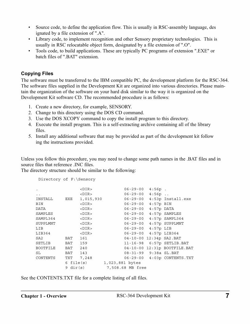
• Source code, to define the application flow. This is usually in RSC-assembly language, designated by a file extension of ".A".
• Library code, to implement recognition and other Sensory proprietary technologies. This is usually in RSC relocatable object form, designated by a file extension of ".O".
• Tools code, to build applications. These are typically PC programs of extension ".EXE" or batch files of ".BAT" extension.
Copying FilesThe software must be transferred to the IBM compatible PC, the development platform for the RSC-364.The software files supplied in the Development Kit are organized into various directories. Please main-tain the organization of the software on your hard disk similar to the way it is organized on theDevelopment Kit software CD. The recommended procedure is as follows:
1. Create a new directory, for example, SENSORY.2. Change to this directory using the DOS CD command.3. Use the DOS XCOPY command to copy the install program to this directory.4. Execute the install program. This is a self-extracting archive containing all of the library
files.5. Install any additional software that may be provided as part of the development kit follow
ing the instructions provided.
Unless you follow this procedure, you may need to change some path names in the .BAT files and insource files that reference .INC files. The directory structure should be similar to the following:
Directory of F:\Sensory
. <DIR> 06-29-00 4:56p .
.. <DIR> 06-29-00 4:56p ..INSTALL EXE 1,015,930 06-29-00 4:53p Install.exeBIN <DIR> 06-29-00 4:57p BINDATA <DIR> 06-29-00 4:57p DATASAMPLES <DIR> 06-29-00 4:57p SAMPLESSAMPL364 <DIR> 06-29-00 4:57p SAMPL364SUPPLMNT <DIR> 06-29-00 4:57p SUPPLMNTLIB <DIR> 06-29-00 4:57p LIBLIB364 <DIR> 06-29-00 4:57p LIB364SA2 BAT 161 04-10-00 12:34p SA2.BATSETLIB BAT 159 11-16-98 6:57p SETLIB.BATBOOTFILE BAT 240 04-10-00 12:31p BOOTFILE.BATSL BAT 143 08-31-99 9:38a SL.BATCONTENTS TXT 7,248 06-29-00 4:03p CONTENTS.TXT
6 file(s) 1,023,881 bytes9 dir(s) 7,508.68 MB free
See the CONTENTS.TXT file for a complete listing of all files.
7RSC-364 Development KitChapter 1 - Overview

8 RSC-364 Development Kit Chapter 1 - Overview
Setting up the EnvironmentIn the listing of the directory structure, note a number of batch files at the root of the Sensory library.These files are used to invoke various tools such as the assembler and linker, and to set the library pathenvironment variable, so they must be in your DOS path. This is most easily done by editing yourAUTOEXEC.BAT file to include the Sensory directory in your "PATH=" statement. Note that this willnot take effect until you re-boot, so you may also add to the path immediately by typing the following(substitute your path for "D:\SENSORY"):
D:\Sensory>SET PATH=%PATH;D:\Sensory
If you do this, be sure to edit your AUTOEXEC.BAT, too.
As described below, Sensory recommends a development approach using "build files". This approachwill add to your DOS environment variable strings, which may require allocating more memory for DOSenvironment variables. This can be done under Windows by the following:
1. Right-click on the DOS Icon and select "Properties".2. Select the "Memory" tab3. In the "Initial environment" window, select a number, at least 1024.4. Click on "OK"
You may also edit the MSDOS.PIF file to change the environment size.
In DOS-only development environment, the environment size can be enlarged to 1024 by adding the fol-lowing line to your CONFIG.SYS file:
shell=command.com /e:1024 /p
Note: This also works for windows 95/98
The final step in setting up the environment is to run the SETLIB.BAT file, which assigns new environ-ment variables needed by the "build files". The syntax is SETLIB <sensory directory>.
D:\Sensory>setlib d:\sensory
D:\Sensory>rem Sets the path of the root of Sensory's Library
D:\Sensory>rem usage: SETLIB [path]
D:\Sensory>set LibPath=d:\sensory
D:\Sensory>set casmspec=-DLibPath:d:\sensory
D:\Sensory>
Configuring the Serial port of your PCMany developers will use the PC serial port for downloading programs (using Sensory's bootloader soft-ware) and also for interacting with RSC applications (using a terminal emulator such as Hyperterminal).These two applications may compete for the PC serial port and can cause conflicts. If you use port2 forcommunication with the RSC, such conflicts can be minimized by inserting the following line in your\WINDOWS\SYSTEM.INI file under the [386Enh] section:
COM2AutoAssign=2
If you use port1, enter
COM1AutoAssign=2
For additional information about using the "COM<n>AutoAssign=" setting, please see the followingarticle in the Microsoft Knowledge Base:
Q130402 Device Contention in Windows
Also, verify that the terminal emulator is using the correct IRQ and I/O address settings for the COMport it is using.
This completes the software installation and environment setup. Any additional software tools may beinstalled now.
Software ContentsThe information below describes the general contents of the various subdirectories.
The \BIN directory contains the executable tools programs.
The \DATA directory contains directories with speech data files, Speaker Independent recogni-tion weight files, and music data files. These files will be useful in prototyping.
The \LIB directory contains directories with the various object modules and includes files forSensory technology code. Your programs will link or include these modules as required.
The \LIB364 directory contains directories with the various object modules and includes files forSensory technology code that is specific to just the RSC-364. Your programs will link or includethese modules as required.
The directory \SAMPLES contains directories with sources and executables for demo programsthat illustrate the technologies supported in this release that are not specific to the RSC-364.
The directory \SAMPL364 contains directories with sources and executables for demo programsthat illustrate the technologies supported in this release that are specific to the RSC-364. Thesample programs are useful templates for developing applications that are more complex.
9RSC-364 Development KitChapter 1 - Overview

Each sample described below resides in its own subdirectory, which includes a "build" batch file. These batch files act as a "poor man's maker" to automate the assembly and linking operationsand to facilitate using options such as different memories, options, or features. Each sample alsoincludes a README file describing how to configure the hardware to run the demo. Eight ofthese demos are included in the ready-to-run Sample Flash, which is installed in location TSOP-B on the Memory Module board. When that Flash is installed in socket TSOP-B and shortingblock JB4 (PC_DOWNLOAD) is installed, one of these programs can be selected using therotary switch on the Memory Module. Other samples or developer programs may be loaded intothe Sample Flash using the BOOTLOAD tool, or they may be run from an EPROM or ROMemulator in DIP socket U1. Following are brief descriptions of the sample programs.
Within the \SAMPLES directory are subdirectories with sample code:
The directory SIMPLE contains a simple test program, TIMING. The program is simple enough (itrequires no technology code) that you should be able to re-create it at any time. It defines its own RAMmemory structure. This small demo wiggles lots of pins, allowing you to use an oscilloscope to compareexternal read/write signals with the data sheet and to verify that things are working as they should. Thisprogram makes a good introduction to the simulator, too. To build this program simply type "buildtmg".It operates from an EPROM or ROM Emulator in DIP socket U1.
The TUTORIAL program in the TUTORIAL directory is intended for use with the RSC-364 simulator.This program is not typically executed on the RSC-364, but only on the simulator. See Chapter 5,Simulator, for more details.
Within the \SAMPL364 directory are subdirectories with more complex sample code:
The SI6 directory contains files for a sample of Speaker Independent recognition. One configuration ofthe SI6 sample is included in the Sample Flash as sample #0. See the README.TXT file for instruc-tions to run this sample. This sample will let you experiment with Speaker Independent recognition.Study the calling examples. Also see Using Pattern Generation, Using (Speaker Independent) SpeechRecognition and Using Speech Synthesis. Use SW-A or SW-B on the Motherboard for the switchrequired to run this sample. This sample is configured to demonstrate Simultaneous RecordRP andPatgen using the SPFlash memory.
The directory RS232 contains another small program, SERIAL, that illustrates use of the RS-232 rou-tines for communicating with a terminal (commonly a PC terminal-emulator program). This programuses the standard RSC-364 RAM memory structure, and it is branched to by the standard startup memo-ry module, modified for this sample. Since this program has minimal technology requirements but needs"hooks" to that code, this is a good example to use in learning about RAM allocation, IO configuration,and other startup issues. This sample operates from an EPROM or ROM Emulator in DIP socket U1.
The MUSIC folder contains a sample program that plays any of three tunes. This demonstrates the four-voice music synthesis capability of the RSC family of chips. Contact Sensory for information on devel-oping custom tunes, ensembles, or musical instruments. This MUSIC program is included in the SampleFlash as Sample#7.
The directory SPKRDEP contains files for a demonstration of Speaker Dependent recognition. The
10 RSC-364 Development Kit Chapter 1 - Overview
SPKRDEP sample is included in the Sample Flash as sample #1. See the README.TXT file forinstructions to run this sample. See also Chapter 2, Using Speaker Dependent Speech Recognition. Thissample uses SPFlash for read/write storage, but it can also be built with assembly-time options for stor-ing templates in either the 24C65 Serial EEPROM or the SRAM. The version in the Sample Flash illus-trates "name tagging", where recognition confirmation is provided by playing a stored voice recordingmade during training. Three different language versions may be linked: English, Japanese, or Korean.
The directory PASSWORD contains files for a demonstration of one-word Speaker Verification. ThePASSWORD sample is included in the Sample Flash as sample #6. See the README.TXT file forinstructions to run this sample. See also Chapter 2, Using Speaker Verification Technology. This samplealso illustrates power down ("sleep mode") and storing words on-chip. No external read/write memory isrequired to run this sample. (Note: A typical Speaker Verification application should use at least twowords -- preferably more -- in a sequence to obtain a reasonable security level. This one-word sample isdesigned for demonstration purposes rather than serious security applications).
The WORDSPOT directory contains files for a demonstration of one-word or sequential two-wordWordspot Recognition. The WORDSPOT sample is included in the Sample Flash as sample #4. See theREADME.TXT file for instructions to run this sample. See also Chapter 2, Using Wordspot SD SpeechRecognition. This sample stores templates in on-chip memory, so no external read/write memory isrequired to run this sample.
The directory RECORDER contains files for a demonstration of a Voice Recorder. This will digitallyrecord and playback audio sounds. The RECORDER sample is included in the Sample Flash as sample#5. See the README.TXT file for instructions to run this sample. See also Chapter 2, Using VoiceRecord and Playback. The sample stores the recorded voice in the SPFlash.
The directory CLSI contains files for a demonstration of Continuous Listening using SpeakerIndependent speech recognition. This sample operates from an EPROM or ROM Emulator in DIP sock-et U1. See also Chapter 2, Using Continuous Listening. Continuous Listening can also be used with SDor SV technology. The Speaker Verification sample can be configured for CL with SV.
The directory MATH contains another SI sample program. This sample gives additional working codesamples of pattern generation, prompting, and SI recognition. It also illustrates usage of the recognitionconfidence and class to provide a range of appropriate speech feedback.
The directory SPKRVER contains a second Speaker Verification sample program (in addition to PASS-WORD) that can be configured in a number of different ways using the builder batch file,BUILDSV.BAT. The SPKRVER sample is included in the Sample Flash as sample #2. In the defaultconfiguration it provides a 4-word sample security application with the words stored on-chip. Promptinglanguage and debugging output may also be easily configured. The sample can be configured forContinuous Listening using SV words (see Using Continuous Listening).
The directory FASTDIG contains a sample program illustrating Dual Recognition Technology (DRT)and Pattern Queuing. This program prompts for a 7-digit string (e.g., a telephone number), then queuesthe sequence of seven patterns, allowing the digits to be spoken quickly. After all the digits have beenspoken and queued, the program recognizes them with high accuracy using fast DRT. This sample isincluded in the Sample Flash as sample #3. See also Chapter 2, Using Dual Recognition Technology,and Chapter 3, "Using On-chip Pattern Storage".
11RSC-364 Development KitChapter 1 - Overview
The directory TTONES contains files for a demonstration of DTMF (touch-tone) synthesis. This sampleoperates from an EPROM or ROM Emulator in DIP socket U1. See also Chapter 2, Using Touch-toneSynthesis.
4. Assembling, Linking, and Loading Modules and ProgramsSensory uses the IBM-PC as the hardware platform for RSC software development. Source code isdeveloped using standard PC editing tools under either DOS or Windows (saved as text files). Sensorydoes not provide an editing tool. Sensory's assembler tool, SASM2.EXE, and the linker tool,CLINK.EXE, run under DOS to create a binary file containing the executable RSC code. This file mustthen be transferred to a form that allows the RSC to execute it, typically either using an EPROM orFLASH programmer or a ROM emulator. The manual section "Assembler & Linker" contains referenceinformation regarding detailed usage of these two tool programs. This section offers an overview of theiruse. (Note: The assembler and linker are actually cross-tools, since they execute on the PC, not theRSC.)
The assembler operates on one file at a time; it is usually invoked using the batch file, SA2.BAT, con-tained in the root of the Sensory directory. SA2 accepts the filename of an assembly source file and pro-duces a relocatable object file (.O) and a listing file (.LST). The assembler must operate on each file thatexists as source code. Most Sensory library modules are supplied in pre-assembled object format, not assource code. The standard file extension for assembly source files is ".A". The batch file, SA2, requiresonly the filename; it automatically appends the .A extension if none is given. An error during assemblywill cause SA2 batch processing to pause for the user to enter a keystroke.
After the required source files have been assembled, the linker is invoked to link all the object modulesneeded for the program. Since linking normally involves many file names, the linker is usually run usingthe batch file, SL.BAT, also contained in the root of the Sensory directory. This command file requiresno arguments – it reads a list of object file names from a command file, LINK.CMD, contained in thesource directory. The linker combines all the object modules listed in LINK.CMD into a single binaryexecutable and produces output files including a .MAP file and a .BIN file. The .BIN file is the binaryRSC executable. Each application needs its own unique command file. The command file, typicallynamed LINK.CMD, is usually generated automatically by the build batch file described below. See thesample programs for examples.
After linking, the .BIN file on the PC must be transferred to a memory device that the RSC can refer-ence as Code Space. This could be an EPROM, a mask-programmed ROM, or -- in high-volume cases --a custom RSC-364 ROM mask. During development it is convenient to use a ROM emulator for thispurpose. A ROM emulator is supplied with software that allows downloading the .BIN file through acable connected from the PC's parallel port to a circuit board containing a dual-port memory. A secondcable from the ROM emulator connects to a socket on the developer's hardware. The RSC executes thecode from the ROM emulator. Using such a tool, the developer can edit changes to the source, re-assem-ble, re-link, download, and begin execution in just a few seconds. Some developers may have difficultyfinding ROM emulators. Sensory has had good success with ROM emulators from Tech Tools, PO Box462101, Garland, Texas, 75046 ([email protected], or www.tech-tools.com). Many other companiesmake comparable products. Note that special emulators or adapters may be required to allow a ROM
12 RSC-364 Development Kit Chapter 1 - Overview
emulator to operate with the RSC-364 Development Kit at 3V. The Tech Tools model FR2-xM-90 orEcono Rom ER2-xM-90 along with the ADP3V external power supply and low voltage adapter are rec-ommended.
This release supports an alternative to ROM emulation for loading programs during development. This"bootload" approach transfers the binary file information from the PC to the Sample Flash on the DKMemory Module using the serial RS-232 port. Loading a program with this method is more cumbersomeand slower (about 40 seconds) than using a ROM emulator (about two seconds), but it requires no addi-tional hardware. See Using The Bootloader section in the Software Development chapter for details. Seethe Memory Module Configuration section below for information about configuring the developmentenvironment for either bootloading or ROM emulator development. Support for the bootload configura-tion allows the Demo Unit to be used as a primary development platform.
Sensory recommends using a batch builder methodology for building applications. The sample belowillustrates this methodology for assembling and linking the sample program, TIMING.A. The BUILDT-MG.BAT batch file assembles TIMING.A, creates a linker command file, LINK.CMD, and executes thelink to create the binary, TIMING.BIN, and associated files. Portions in bold are typed by the developer.As shown, the linker command file, \SAMPLES\SIMPLE\LINK.CMD, includes just the source file. Theother sample programs include library files, and the LINK.CMD for those samples is much larger.
A limitation of the linker command file is that it cannot have comments. Using the build file, BUILDTMG.BAT, allows adding comments and notes, and makes it easy and clear when trying differentlinking alternatives. See the sample CLSI for a more extensive illustration of using the build file andincorporating options. All of the sample programs include build files.
X:\samples\simple>buildtmgRSC-264/364 ASSEMBLER V.2.01, release 14 Dec. 1998copyright (c) 1995-1998 Sensory Inc.** using MAXce.DEF Instruction Set, last rev:12-14-98 15:16:53
No errors in assembly.CLINK cross linker V2.0mCopyright (C) 1994 by Sensory Circuits,ECO,&AWE
No link errors.X:\samples\simple>type link.cmdtiming
X:\samples\simple>
Only the TIMING.O file is linked in this sample. In any example using technology code the followingfiles must always be linked (plus any others required by specific technologies):
;required link files with EVERY technology application\lib\startup\startup.o (or a local copy)\lib\startup\config (or a local copy) \lib\util\delay14 \lib264\util\analog \lib264\const364
13RSC-364 Development KitChapter 1 - Overview
5. Memory Module ConfigurationThe RSC-364 Development Kit consists of the three main modules.
• DK264T/364 Motherboard • DK264T/364 Memory Module• DK264T/364 I/O Module
A detailed description of the hardware configuration capabilities is contained in Chapter 4, Hardware.
The DK264T/364 Memory Module contains IC memory devices, sockets, and design features thatshould be understood by the programmer and hardware designer. The module, in conjunction with themotherboard, supports development of products in a variety of configurations:
• Compact products intended for production with all code executed from a single 64K ROM. TheROM could be external or could be the internal ROM in the RSC-364 ("Custom ROM" programs). SI6 might be an example of such a program.
• Products that may use up to 64K memory for executable code and fixed data such as synthesis words, but which require additional external read/write memory for storing templates, voice recordings, or other application-specific data. Recorder could be an example of such a product. A custom ROM would allow all code and static data to be on-chip, but a read/write memory would also be needed.
• Large scale RSC-364 products requiring more than 64K of code and fixed data, such as a product with a large synthesis vocabulary. These products can place recognition weights and synthesis data in Data Space, allowing access to more than 64K by using Banked Data Space. For a more complete discussion of this concept refer to Building Multi-Bank Systems in Chapter3. Because an external ROM is needed to hold fixed data, this configuration would typically notuse the RSC-364 internal ROM. Some applications may contain more than 64K of executablecode, requiring Code Bank Switching. Code Bank Switching is not supported in this release.
Basic Configuration JumpersThe four jumper blocks at JB2, JB3, JB4, and JB6 are used to configure one of four standard operatingconfigurations. Normally no more than one of these jumpers should be installed at any one time (but seeDIP socket U1, below). Non-standard configurations may require removal of all these jumpers. The PC-DOWNLOAD configuration executes special Sensory code from a device installed in socket PLCC-Athat transfers RSC programs from the PC into the Sample Flash in TSOP-B for execution. The otherthree jumpers configure for running user code from one of three sockets, U1, PLCC-A, or PLCC-B, orfor providing access to flash or SRAMRAM devices. Refer also to the Hardware Chapter for more information on these jumpers.
Default ConfigurationThe RSC-364 Development Kit is shipped pre-configured for "bootload" development. In this configura-tion the hardware is compatible with Sensory's Demo Unit.
14 RSC-364 Development Kit Chapter 1 - Overview
• Socket PLCC-A contains an OTP programmed with the RSC code to transfer data over the RS-232 serial connection. This program runs when the system is initialized with the BOOT switch depressed.
• Socket TSOP-B contains a pre-programmed 4 Mbit Code Space flash, "Sample Flash". This program runs when the system is initialized with the BOOT switch not depressed.
• Socket PLCC-B contains a 2-Mbit Data Space flash, "SPFlash" (sector programmed type 29xx020). This is the default read-write device.
• Jumper JB4, PC_DOWNLOAD, is installed and jumpers JB2, JB3, and JB6 are removed.
In this configuration the PROGRAM SELECT switch runs any of eight programs contained in theSample Flash. Any of these selections can be re-programmed with developer's application code using thebootload procedure (See Using the Boot Loader in the Software Development chapter). This configuration is suitable for developers who will not use a ROM emulator, and for whom the fol-lowing limitations are acceptable:
1. The 29xx020 2Mbit flash is suitable as the only Data Space storage.2. The 24C65 Serial EEPROM may or may not be used.3. The Code Space requirements (program plus fixed data) are no more than 64K bytes.
If you need additional or different resources, or if you want to use a ROM emulator, you will need to useDIP Socket U1 for development.
DIP Socket U1This socket accommodates an EPROM or ROM emulator of size up to 4 Mbits. To use DIP Socket U1for development you must reconfigure the Memory Module board. Your code will execute from thedevice installed in the DIP Socket. First, realize that you always have access to serial EEPROM for stor-ing data and up to 64 templates per device, since serial EEPROM is not in Data Space. Next, decidewhat Data Space resources your application will need:
1. Code Space only. (example: Program does not need flash for voice recordings, is small enough to fit with all SI weights and synthesis data into 64Kbytes)
2. Read-Only Data Space (example: Program using SI and a large amount of synthesis, but no voice recordings. SI weights and synthesis data can be placed in Data Space)
3. Read-Write Data Space (example: Program with SD and voice recording confirmation)4. Mixed Read-only and Read-write Data Space (example: program+synthesis+weights is larger
than 64K, and read-write memory is needed for voice recordings)
Based on the resource needs above, configure the board as described and install your EPROM/ROMEmulator in DIP Socket U1:
1. No Data Space. To select this operating mode install a shorting block at JB2: CODE_DIP andremove any shorting blocks in the adjacent three locations.
2. Read-Only Data Space: Most developers will use U1 for a combined Code+Data Space socket. In production, a single ROM will be used. DIP Socket U1 supports development of programs
15RSC-364 Development KitChapter 1 - Overview

with 512Kbits (64K bytes) of Code Space ROM and up to 3.5 Mbits (448 Kbytes) of Data SpaceROM. (total Code+Data ROM =4Mbits). Extended address bits (A16 up to A21) are controlledby developer-specified IO pins (P0.2-P0.4 recommended). To use the Data Space ROM capabili-ty of U1, you must build the required decoding circuitry in the prototyping areas of the MemoryModule and remove JB2 and the three adjacent jumpers. See a sample schematic in BuildingMulti-Bank Systems in the Software Development chapter. A simpler example can be found inthe CLSI sample.
3. Read-Write Data Space. There are three cases: A) SRAM, up to 32K bytes. In this case, install jumpers JB6:DEMO-PLCC-B (enables SRAM as
Data Space) and JB2:CODE-DIP. Remove the 29xx020 Flash from socket PLCC-B to preventbus conflict with the SRAM.
B) The 29xx020 SPFlash or another pin-compatible part is the (only) Data Space device. First installboth jumpers JB4:PC_DOWNLOAD and JB2:CODE_DIP. JB4 enables PLCC-B as Data Spaceand JB2 enables U1 as Code Space. Next, remove the Sample Flash at socket TSOP-B to preventbus conflict with the DIP socket. This is required because JB4 enables both the socket at PLCC-B (where the SPFlash is installed) and TSOP-B. NOTE: Take care in removing the Sample Flash.See Installing and Removing the Sample Flash in Chapter 4 for assistance.
C) The Data Space device is not SRAM or pin-compatible with the 29xx020 SPFlash, or multipleData Space devices are needed. You must use the prototyping section of the Memory Module towire the appropriate circuitry. Any available sockets may be used.
4. Mixed Read-only and Read-write Data Space. You must use the prototyping section of theMemory Module to wire the appropriate circuitry. Any available sockets may be used.
PLCC-BSocket PLCC-A provides up to 4 Mbit of OTP ROM for Code and/or Data. This socket normally con-tains a 2 Mbit 29xx020 SPFlash device accessed as Data Space, with a Code Space device in either U1or TSOP-B as described above. The full 18-bit addressing capability of this part is available by installingJB4:PC-DOWNLOAD. Sensory library code supports this device for template and voice recording stor-age.
PLCC-B may also be used for Code Space in the development of applications usingOneTimeProgrammable (OTP) ROMS up to 4 Mbit (Code and Data ROM). You must use the prototyp-ing capability of the Memory Module to wire the appropriate circuitry.
Socket PLCC-ASocket PLCC-A provides up to 4 Mbit of OTP ROM for Code and/or Data, similar to PLCC-B.Normally this socket contains a 2Mbit OTP with the "bootloader" RSC program for PC-DOWNLOADoperations. When the system is initialized with the BOOT switch depressed, the code in PLCC-A exe-cutes, transferring data from a program running on the PC to devices on the Memory Module. A sepa-rate document describes the bootloader (see the Design Notes Section).
This socket can also be used with a non-boot Code Space program by installing JB3:CODE-PLCC- A.When used with JB3 installed, certain restrictions apply:
16 RSC-364 Development Kit Chapter 1 - Overview
• Only a 1Mbit or 2Mbit ROM can be installed, and only 512kbits may be addressed, controlledby address bits [A15:A0] of the RSC. Address bits A16 and A17 are grounded. A18 is ignored.
To employ this socket for general purpose Data Space read-only or read/write use, remove JB3 and con-nect the required decoding circuitry in the prototyping area. With JB3 removed, the socket can supportup to 4 Mbits.
Serial EEPROM U12Many Speaker Dependent applications need to store only templates, and a serial EEPROM is ideal forthis. The 24C65 device at U12 can be configured to operate with any two IO signals on the same port(P0 or P1).
Flash TSOP-AThis IC site is reserved for user-specified memory parts. It is a memory footprint accommodating a 32-pin 8mm 20mm TSOP package.
Flash TSOP-BThis 4Mbit Flash device, M29W400T, is normally used for PC-DOWNLOAD operations, in which caseit contains up to eight separate Code Space executable images. The rotary PROGRAM SELECT switch,S2, selects one of the eight programs. In its shipping configuration this Sample Flash contains the 364sample programs. The bootloader may be used to replace these programs with developer programs.The Sample Flash can also be used for storing voice recordings, templates, and other data requiring non-volatile read/write memory. Connect the required decoding circuitry in the prototyping area. There ispresently no software driver support for Data Space applications of this device.
Prototyping AreaThe Memory Module is designed for flexibility. A minor amount of custom wiring can accommodatemany different memory configurations. An area near the edge connector contains thru-holes for the con-trol signals from the RSC-364 required for attaching to the RSC bus. Near each socket are thru-holeswith the control signals for that socket. A variety of different memory devices may be installed in thesockets or are already assembled to the board. The RSC control signals should be connected to theappropriate memory device signal pins as required for a specific memory design. Three 14-pin dip sock-ets are provided to aid in construction of memory decoding circuitry. Two 40-pin DIP socket areas areprovided to allow use of other memory packages (power and ground are not connected in this area).Additional Memory Modules may be ordered – please contact Sensory for ordering information.
6. RAM AllocationStudy the sample programs for definitions of RAM memory usage. Although the RSC-364 contains 448bytes of Register Space RAM, almost all of this is needed for Sensory's technology code, despite heavyoverlaying (e.g., speech synthesis and speech recognition uses the same RAM memory). The limited on-chip RAM requires careful product specification and design to assure memory availability and to avoidunintended interaction with Sensory's technology code. The only RAM always available for applications code is a contiguous block of 32 bytes. This lower limitcan be extended by virtually every application to at least 48 contiguous bytes (this is the default configu-
17RSC-364 Development KitChapter 1 - Overview
ration), and in most cases 58 contiguous bytes are readily obtainable. To assure no inadvertent overlay-ing of applications variables and Sensory variables, user variables should be allocated only from thisuser area. The file USERMEM.INC should be included to establish references for this memory. Alsoinclude MEMORY.INC to reference other common variables including some RAM locations that havepublic labels ("a", "dpl", "r0", etc.) because they are used to pass parameters to technology code mod-ules, and may generally be used for temporary storage. Using the RSC-364 Memory Map in Chapter 3describes the RAM in detail, and points out additional RAM available for applications under certain cir-cumstances.
An additional on-chip memory area on the RSC-364 can be used for storing patterns or templates in cer-tain applications. See the section Using On-Chip Template Storage in Chapter 3 for more information.
7. Allocating ROM for Speech and Weights Building an application with either speech synthesis or Speaker Independent recognition requires linkingyour code with data files provided by Sensory. Speech data and weights are provided as object files thatcan be directly linked using the object linker (CLINK.EXE). Each separate synthesis vocabulary or SIrecognition weight set has a name that is declared PUBLIC in the .O file. Normally the files containingthis data would be included in the LINK.CMD linker command file as shown in the samples. A common problem for applications with large amounts of speech is "ROM crunch" – insufficient spacein the 64K Code ROM. When the speech has been compressed as much as possible and there is still notenough room, ROM allocation becomes a problem of managing memory larger than the 16-bit address-ing capability of the RSC-364. For programs with moderate-sized executable code (64Kbytes or less) butlarge data requirements, placing the speech data in Data Space provides enough room.
Data Space Placement of Speech and WeightsData Space placement of weights, speech, or other fixed application-specific data (e.g., tables) requiresbuilding two or more ROM images, one with the executable Code Space code, and the remainder withData Space data. The linker can only deal with one 64Kbyte ROM bank, so manual assistance isrequired to resolve references between the two ROMS. This section describes that process for a128Kbyte application using two extra files, IMPORT.A and LINKDATA.A. (The names are arbitrary.)Applications with Data Space larger than 128K follow the same general method, but need separateimports defined for each data bank.Typically the Data ROM will contain one or more speech vocabularies and perhaps some SI weights setsor other data. Each object to be accessed from the Code ROM must have a PUBLIC label (speech,weights, and confidence levels for recognition sets have this automatically). The labels for any directlyreferenced application-specific data must also be PUBLIC. The Data ROM is typically built first, sincethe Code ROM references the Data ROM but not vice versa.
The steps to building the ROMs are:
1. Create a file, LINKDATA.A, containing any application-specific tables or information you wanto access in Data Space. If you do not need any such data, the file should contain simply an END directive. Note this file is required.
2. Create a linker command file (similar to LINK.CMD) containing the names of all the Data
18 RSC-364 Development Kit Chapter 1 - Overview

Space files. The first file in the list must be LINKDATA. Use the "-o<filename>" command-line option to give the .BIN file a different name.
3. Assemble LINKDATA, then link the Data Space ROM using the -m(map) option:\BIN\CLINK @<LINKFILENAME> -M
4. Use the map file from the Data Space ROM to determine the addresses of all public symbols5. Edit these values into the IMPORT.A file as EQUates. All the symbols must also be declared
PUBLIC in IMPORT.A.6. Assemble IMPORT.A and link it into the Code Rom to resolve the Data Space addresses.
The Continuous Listening SI sample, CLSI, can be configured to use Data Space placement, and it hasbeen set up to illustrate the process described above. See also Building Multi-Bank Systems and section6, above, RAM Allocation.
When 64K Code Space is not enoughSome very large, complex applications may need more than 64K of Code Space ROM. This requiresCode Bank Switching. The RSC-364 Development Kit with Sensory Speech 6 Technology does not sup-port code bank switching.
Large Data Space Memory Model and Rapid Vocabulary PrototypingSpeech Synthesis data and SI Recognition weights may be located (independently) in either Code Spaceor Data Space. A single 64K binary can contain executable code, speech data, and weights all in CodeSpace. Alternatively, a larger 128K program can be built with 64K of executable code and 64K ofspeech data plus recognition weights (or 64K of code plus weights and 64K of speech data). A largerprogram of this type can fit in a single 1 Mbit ROM. Expansion to even larger Data Spaces is straight-forward.
One benefit of placing speech data in Data Space is that a modest vocabulary can be processed to fit into64K by Sensory's linguists very quickly and at a reduced cost compared to squeezing it to fit in, say,32K. This can allow more rapid prototyping with correct target vocabulary. As a rule of thumb, rapid-turnaround compression is only possible with at least 1600 bytes/word of available memory for higherquality and at least 1100 bytes/word for lower quality. Thus, a 64K Data Space ROM could hold about40 higher quality words, or about 60 lower quality words. Vocabularies of this size can be processed by Sensory linguists and returned promptly.(NOTE: Thedeveloper must take care to assure proper device selection when using Data Space speech if read-writememory addressable in Data Space is also used for storing templates or voice recordings).
Data Space placement is also valuable for use with "Quick Synthesis", a tool that allows the developer tocreate speech synthesis vocabularies with no Sensory linguistic assistance. This provides quick develop-ment of vocabularies with good quality and compression rates of less than 2600 bytes/word.
8. RSC-264T/364 SimulatorThe RSC-264T/364 simulator is a windows-based program called SIMULATE.EXE. This program simu-lates all processor operations and is very useful for working out timing and checking intermediate com-
19RSC-364 Development KitChapter 1 - Overview

putations. At the level of this simulation, the RSC-264T and RSC-364 are similar, so one simulatorworks for both chips. The simulator allows loading binary executables, and provides single stepping, runto breakpoints, and memory display. This can be of value in testing loop termination conditions, algo-rithms, and other code segments that intensively use the RSC-364 Register Space.
The simulator does not support the specialized on-chip hardware needed for speech synthesis or speechrecognition, so you cannot use the simulator to check these parts of your code. Sensory is aware that thisprogram does not comply with all Microsoft standards for Windows programs.
9. Notes and SuggestionsThis section includes a compilation of helpful information gathered from Development Kit users. Thesenotes should be briefly reviewed for familiarization before using the kit, but most will be more usefullater as reference.
A First ExerciseThe SI6 directory contains the file SI6.BIN. As an exercise, you may want to rename this file to ORIGI-NAL.BIN, rebuild this sample by re-assembling and re-linking (by running BUILDSI6.BAT), and con-firm that the final SI6.BIN file matches this ORIGINAL.BIN file.
Debugging HelpThe color LEDs and switches SW-A, SW-B, and SW-C are for general-purpose use in debugging andfor operating the sample programs. The disk directory DEBUG_S contains object modules for a speechdebugger that provides spoken data information about the contents of internal memory ("speech dump").This can be a useful complement to the emulator. The speech debugger can also provide Sensory stan-dard recognition feedback (class, level, silence, maxpower) during recognition. This capability incorpo-rates a DebugEnable byte that can be set to different values to control the amount of feedback provided(the default is 0: all disabled). See Using Debug Speech in chapter 3, for information on standard feed-back and on using speech output for debugging assistance. "Speech" debugging can alternatively bedirected to the RS232 output by linking a different file.
Named SegmentsThe assembler supports the named SEGMENT directive, which is helpful in determining memory allo-cation from the .MAP file. Liberal use of this directive is encouraged. Small pieces of code in their ownsegments can often be tucked into the holes around speech or weights files by the linker, freeing up moreROM in tight applications.
Recognition SpeedSpeech recognition is a two-step process of collecting data from the speech waveform in real-time whileprocessing to generate a pattern, and then analyzing the pattern with a neural network. The neural netprocessing does not begin until the speech utterance is complete, so there may be a perceptible delayfrom completion of speech until the recognition is finished. This overall delay is the result of a variety ofbuilt-in delays (to improve accuracy), some of which can be reduced. The ultimate minimum delay isdetermined by the processing time for the neural net, which presently requires from 0.1 seconds (forYes/No) to about 0.3 seconds (for 0-9) using Speaker Independent recognition. The time required for
20 RSC-364 Development Kit Chapter 1 - Overview
Speaker Dependent recognition depends on the vocabulary size -- normally about five msec per vocabu-lary word for large (50-60 word) vocabularies. The maximum SD time per word – about 30 milliseconds– occurs with vocabularies in the range of 8-10 words. A Speaker Dependent parameter, SD_PERFOR-MANCE, may be adjusted to gain quicker recognition processing time at the cost of slightly reducedrecognition accuracy. At the fastest setting, a 10-word SD vocabulary can be recognized in about 50msec rather than the normal 200 msec. Speaker Verification always requires about 30 msec per word inthe vocabulary.
ShoehorningThe limited on-chip resources of the RSC-364 create common problems for many applications develop-ers. These problems include insufficient RAM, insufficient stack, and insufficient ROM.
The usual solution to RAM shortage is overlaying. Overlaying can resolve conflicts between temporaryRAM needs, but it may require re-writing some modules to use different temporary variables. Sensoryrecommends a method of allocating temporary variables using the "set" directive that works somewhatlike the assignment of automatic variables in the C language. This allows a local variable to have ameaningful name in one subroutine, and the same memory location to be used in a different subroutineby a different name. See the RECORDER sample program for an example. Overlaying within USER-RAM cannot solve the need for additional static (global lifetime) variables, however. This involves over-laying into the system RAM. Here are some suggestions for overlaying:
• The 5 bytes at 01Bh-01Fh are available unless Voice Record and Play is used. • The 17 bytes at 010h-020h are available if neither SD Recognition, SV Recognition, Wordspot
Recognition, Dual Recognition, nor Voice Record and Play is used.
10. Error MessagesThe linker requires that the first file linked contain a path to the assembler. This is assured if the file isassembled on the user's computer, as is the case for typical applications. Attempting to link with the firstfile being a library module will cause an error message similar to the one shown below (but with a dif-ferent path to the file, SASM2.EXE).
CLINK cross linker V2.0mCopyright (C) 1994 by Sensory Circuits, ECO, &AWECan't open file 'F:\SENSORY\BIN\SASM2.EXE': No such file or directory
11. Manual ContentsThe RSC-364 Development Kit Manual contains ten chapters designed to allow fast access to informa-tion. The manual consists of the following chapters:
1. Overview. Lists and briefly describes the hardware and software components of theDevelopment Kit. This chapter also describes basic information needed for "getting started" withthe Kit. IF YOU READ NOTHING ELSE, BE SURE TO READ "GETTING STARTED".There are several chapters describing memory module configuration, RAM allocation, ROM
21RSC-364 Development KitChapter 1 - Overview
allocation and a variety of notes and suggestions on using the Development Kit. This sectionalso provides a complete directory listing of all software files provided with the Kit.
2. Technology Library. Describes how an application programmer can access the various speechand audio processing capabilities of the RSC-364. This chapter contains separate sections thatdescribe the initialization, include files, linking, and macros required to access each technology.Separate sections describe Speech Recognition (Independent and Dependent), Pattern Generation,Speech Synthesis, Speaker Verification, Continuous Listening (two sections for the two differentmethods), Wordspot Recognition, Dual Recognition, DTMF, and Voice Recording and Playback.
3. Software Development. Contains reference documents used when programming the RSC-364.The first document describes issues concerning the insertion of silence durations and delayswhen working with speech synthesis. Another important document describes the User MemoryMap of the Register Space (SRAM) available to programmers. Other documents describe use ofthe system configuration modules, Building Multi-Data-bank Systems, software routines forinterfacing to a variety of external memories, use of Debug Speech, PC (RS232) Output, and theFloating Point Library.
4. Hardware. This chapter contains descriptions, schematics, and parts locator drawings for thePrinted Circuit Assemblies provided in the Development Kit. This section also includes listingsof pinouts, connectors, jumper configurations, LEDs, switches, and other hardware items.
5. Simulator. This chapter describes the Personal Computer (PC) software program,SIMULATE.EXE, a software simulation of the RSC-364. The chapter gives guidelines for use,including a tutorial.
6. Assembler and Linker. Describes usage of the Sensory cross assembler, SASM2, includingcommand line options, source syntax, and directives. There is also a description of assemblerextensions (Intel 8051-like instructions) for the RSC-364. This chapter also provides referencematerials for the Sensory object linker, CLINK. The assembler, linker, and simulator all run onthe IBM-PC platform.
7. Upgrades. This chapter provides a guide to experienced developers for "porting" RSC-364applications to this library release 6. It also outlines how to incorporate new features into existingapplications. If you are a new developer you may safely ignore this chapter.
8. Data Book. Contains the Data Book for the RSC-364. This provides a detailed description ofthe chip's architecture, features, memory and I/O interface, bonding pad descriptions, electricalcharacteristics, instruction set and other details of its use.
9. Design Notes. Contains detailed and comprehensive documents that will help a product designerdefine, specify, and develop successful products utilizing speech recognition and synthesis.These documents contain many suggestions for various stages of the product design cycle, that ifclosely followed will yield products with high recognition accuracy, quality, and reliability.
10. Support. Describes the Sensory support and warranty policies.
12. Development Kit ContentsThe RSC Development Kit includes the hardware, software, programming tools, and documentation nec-essary to program the RSC-364. Following is the complete list of items included in the kit (improveddesigns with different part numbers may be substituted):
22 RSC-364 Development Kit Chapter 1 - Overview

• DK264T/364 Motherboard - one of the two primary development hardware platforms (1)• DK264T/364 Memory Module - the other primary development hardware platform (1)• DK264T/364 I/O Module – platform enhancement with a prototyping area with a con
nection to the Sensory's 12-key keypad for developing applications. (1)• A 12-key keypad with a telephone-like key arrangement (1)• Microphone, modified by Sensory (1)• Speaker - 8 Ohm (1)• Spare RSC-364 chips (2)• Spare 3V 4MB Flash IC M29W400T (1)• Spare 5V 4MB Flash IC M29F400T (1)• Spare 3V 2MB Flash IC SST29LE020 (2)• Spare 5V 2MB Flash IC SST29EE020 (2)• Cable assembly for power connection (1)• Software Diskette (1) • Demo Unit 364 Software CD (1) • Jumper wires, installed (5)• Bootload OTP (1)• RSC-364 Development Kit Manual (1)
13. Software Development Library ContentsRefer to the library file \CONTENTS.TXT for a complete listing of the files in the SensoryDevelopment Kit Software (compressed in INSTALL.EXE).
14. Sample Program User InstructionsThis section describes the use of the Sample programs, the sources for which are included in the devel-opment kit. The goal of the Sample programs is to demonstrate Sensory technologies in a straightfor-ward manner. Another group of programs, the Demo programs, is supplied with the Sensory RSC-364Demo Unit. These Demo programs have advanced features that are useful for evaluating the technolo-gies. Sources for these programs are not included in the Development Kit because their feature complex-ity obscures the tutorial goal of the Sample programs. A diskette with the additional Demo programsfrom the RSC-364 Demo Unit has also been included with the Development Kit. You may load eitherthe Demo programs or the Samples programs using the bootloader. See the Design Notes section forinstructions on operating the 364 Demo programs.
The sample programs demonstrate the following technologies:
23RSC-364 Development KitChapter 1 - Overview

Using the SamplesThese samples provide simple illustrations of each technology available on RSC-364. An appropriatesample program is commonly used as the starting "template" for a custom application. Changes to theusage or application flow of any technology can be made for specific applications.Please keep in mind that environmental noise and room conditions may affect speech recognition inthese samples. Different types of noise affect the recognizer differently: directional noise is easier toscreen out than ambient noise. In addition, a carpeted room absorbs noises while hard floors reflectthem. Thus, if a radio is playing in the corner of a carpeted room, and the microphone is closer to theuser than to the radio, the recognizer will still achieve a high rate of accuracy. Accuracy will suffer on abusy street corner or in a mall.
Running a Sample ProgramThe eight sample programs are pre-programmed in the 4Mbit Sample Flash installed at location TSOP-B. Software supplied with the Development Kit simplifies re-programming the Sample Flash with thesamples at any time. Verify that the socket labeled PLCC-B contains the IC labeled "Sample Flash". Ifyou are using your development kit for the first time, the Sample Flash chip should be pre-installed inthe TSOP-B socket. If you need to re-install the Sample Flash chip, see Installing and Removing theSample Flash in Chapter 4 for assistance.Next, plug in the microphone and speaker, and then turn on the power. You are now ready to run thedemo programs. Each program is selected with the "Program Select" rotary switch on the memory mod-ule. The demo programs are controlled via three buttons located on the motherboard: SW-A, SW-B, andSW-C. In general, SW-B is used for training (if relevant), SW- A is used for recognition, and SW-C isused to change configuration. All the demos beep at power up to signal that they are ready for use.
Troubleshooting Hints: If the demo does not work, check the following items:
• Make sure the microphone and speaker are plugged into the correct jacks.• Make sure the power supply is at the appropriate level (3.0 or 5.0V).• Check that the Sample Flash is installed with pin 1 correctly oriented in the socket, (text is
upside down) and the lid is securely closed.
SampleName
SwitchNumber
SpeakerIndependent
SpeakerDependent Wordspot
SpeechSynthesis
SpeakerVerification
OtherTechnologies
SI6 0 √ √ Patgen+RecordSpkrdep 1 √ √Spkrver 2 √ √ CL4 w/ SV
Fastdig 3 √ √ √Dual
RecognitionWordspot 4 √ √
Recorder 5 √ √Record and
Play
Password 6 √ √Sleep,
words-on-chip
24 RSC-364 Development Kit Chapter 1 - Overview
25RSC-364 Development KitChapter 1 - Overview
Sample InstructionsSpeaker IndependentThis sample highlights Sensory's speaker-independent recognition using a six-word set: record, play,erase, call, modify, or skip. In addition to recognizing elements of the recognition set, the demo unitcalculates the probability that it has recognized the word correctly. The default configuration stores avoice recording of the word during pattern generation for recognition, and replays it after announcing theresult.
To Start:1. Set the Program Select switch to 0.2. Turn power on.3. A beep will sound to verify that the demo is ready for operation.4. Press button SW-A. The unit gives a speech prompt listing the elements of the recognition set:
"Please say 'record,' 'play,' 'erase,' 'call,' 'modify,' or 'skip.'"5. Say a word from the recognition set, for example "modify."6. The unit replies appropriately, based on the word it has recognized and the confidence level it has
calculated. It also replays a recording of your voice made at step 5. When the unit is sure that it hasnot recognized the correct word, it beeps and asks, "What did you say?" If it is unsure of the result,the beep is omitted.
7. In addition to the recognition responses, the unit will provide feedback when recognition is encoun-tering difficulty. For example, if the user is speaking at a low volume or if the microphone is too faraway, the unit will request, "Please talk louder." If the unit repeatedly responds, "Please talk softer,"one suggestion is to hold the microphone a little further away.
8. Press button SW-B to get a prompt that does not list all the recognition set elements: "Please say aword."
Fast DigitsThe Fast Digits sample simulates a digit-dialing application using Dual Recognition Technology forrecognition. This technology combines the strengths of Speaker Independent and Speaker Dependentrecognition to achieve the necessary high accuracy for this application. Templates for the SD portion arestored in the Serial EEPROM. The patterns to be recognized are "queued" in on-chip memory.
To Start:1. Set the Program Select switch to 3.2. Turn power on.3. A beep will sound to verify that the demo is ready for operation.4. Press buttons SW-A and SW-B together. This erases any patterns stored in the memory and
announces "Memory erased".
To Train the Digit Templates1. Press button SW-A. 2. A speech prompt says, "Please say zero". 3. Say the word "zero" as you would when saying the digits of a phone number.4. A speech prompt says, "Please repeat".
5. Say "zero" a second time.6. The steps from 2-5 repeat for the digits 1-9.7. A beep sounds when templates for all the digits have been trained.
To "Dial" a Number1. Press SW-B.2. A speech prompt says, "please say the number you want to call"3. A "click" prompts you to say a digit.4. Say a digit from 0-9 (be sure to say "zero", not "oh").5. The steps 13-14 repeat until you have said seven digits. The clicks are paced by your speech. A pat-
tern is generated for each word and saved on-chip.6. After seven digits have been recorded, they are recognized.7. Speech tells you the digit string that was recognized.
Record and PlaybackThis demo displays the RSC-364's ability to record and play back audio messages. It also uses speaker-independent speech recognition to choose between the record and playback functions. The length ofmessage that can be stored depends on the memory available – the more memory, The longer the poten-tial message. In this demonstration, about 16 seconds of audio input can be recorded in 512-kbit portionof the 2Mbit SPFlash used for the initial recording.
To Start:1. Set the Program Select switch to 5.2. Turn power on.
To record a message:1. Press the SW-A button.2. The unit prompts, "Record or Play?"3. Respond with "Record."4. The unit says, "Recording."5. Begin recording your message. You can record for the full sixteen seconds or press the SW-A button
to stop recording. If your message exceeds sixteen seconds, the demo will interrupt you with a dou-ble beep.
To play a message:1. Press the SW-A button.2. The unit prompts, "Record or Play?"3. Respond with "Play." 4. The unit says, "Playback."5. The unit then plays back your message.
To change the compression setting:1. Press the SW-B button.2. The unit notifies you of the next compression level, compresses the speech, and plays back the
recording at that level. Note that compression takes roughly as long as the duration of the recording.
26 RSC-364 Development Kit Chapter 1 - Overview
Three different compression levels are possible with this demo: 4-bit, 3-bit, and 2-bit. (For moreinformation on compression, see below.)
3. After the three compressions have been made, subsequent presses of SW-B cycle through them,announcing the level and playing the recording compressed to that level.
The recording remains in flash when the power is turned off.
The record and playback demo shows the RSC-364's ability to perform on-chip compression. The com-pression can be set to different levels depending on the application. Higher bit rates have better soundquality, but require more memory. For example, with 512Kbit of memory, a 16 second message couldbe stored at 4 bits, 8kHz, or 32,000 bits per second (BPS). An 32 second message could be stored in thesame Flash at 2 bits, 8kHz, or 16,000 BPS. With Sensory's silence thresholding technology, even longerrecordings can be made. The level of compression used depends on the quality and quantity of playbackdesired: the more compressed a message, the lower the sound quality, but the lower the memory require-ments.
MusicThe music sample demonstrates the RSC-364 synthesizing high-quality four-voice music from MIDIdata. "Four voice" refers to four different instruments or notes playing simultaneously.
To use this sample, rotate the Program Select knob to position 7. Turn the power on.1. A beep will sound to verify that the demo is ready for operation.2. Press the A button to play Für Elise.3. Press the B button to play Row, Row, Row Your Boat.4. Press the C button to play When the Saints Go Marching In.5. Any tune can be interrupted by pressing one of buttons A, B, or C during play back. 6. When the program has finished playing the tune, or has been interrupted with a button press, it will
respond with a double beep. Press button A, B, or C again to select a song.Because the music is being synthesized in real-time, rather than played from a digital recording, thisthree-song demo is stored in about 4K bytes of ROM.
Voice PasswordThis sample highlights several technologies and features available with the RSC-364.
• The sample will verify a single password after it has been trained. If no word has been trained, itwill return the error message, "Error. Memory empty." The password is stored inside the RSC-364 chip rather than in an external memory.
• The password is stored inside the RSC-364 chip rather than in an external memory. • After training or recognizing the password, the RSC-364 goes "to sleep" (i.e., into a low-
power state). It awakens on a button press (IO signal change).
To Start:1. Set the Program Select switch to 6.2. Turn power on.
27RSC-364 Development KitChapter 1 - Overview
Password Training1. Press the SW-B button.2. The program prompts, "Please say your password."3. Say a password up to three seconds in length. Passwords with multiple syllables work the best.4. The program prompts you to repeat your password, "Repeat."5. Repeat your password.6. If the responses do not match, the program says "Training error," and asks you to
"repeat" again.
After training, the program says "Going to sleep. Press button A to wake up".
Password Listening1. After setting your password, press button SW-A.2. The program prompts, "Please say your password."3. Say a word.4. The program responds with either, "Password accepted" or "Password rejected." The program then
goes back to sleep
Changing Security Levels1. Press button SW-C after power-on.2. The demo says the new security level (1-5).3. Continue pressing button SW-C until the desired security level is reached.4. You can then press button SW-B to prompt and listen for a spoken password.
Some things to try: Using different threshold levels, try varying your intonation or saying a differentword when asked for your password. Ask someone to try to crack your password. Now tell that personwhat your password is and see if the device will accept his or her voice.
Voice Password demonstrates an extremely low cost method of providing biometric security in a varietyof industries, including auto security, home security, appliances, and smart cards. A realistic applicationwould use multiple passwords for improved security.
Speaker DependentSpeaker Dependent demonstrates Sensory's speaker-dependent speech recognition technology. The usercan train the system to identify from 1 to 32 words, with each word trained corresponding to a wordnumber. Any words, from any language, can be used. During training, a voice recording of each wordis made for replay during recognition.
To Start:1. Set the Program Select switch to 1.2. Turn power on.
To Train:1. Press button SW-B. 2. The program prompts, "Please say word one." 3. Say a word.
28 RSC-364 Development Kit Chapter 1 - Overview

4. The program then prompts, "Repeat." 5. The training continues as the unit asks you to say word two, and so on. A set smaller than 32 words
can be created. There are three ways to end training:When all 32 words are trained, the training cycle ends automatically.When silence is recorded during training, the training cycle ends. A beep will signal that training hasended.When the SW-A button is pressed while the unit is listening for a response.
6. If fewer than 32 words are stored, new words can be added at any time by pressing the SW-B buttonagain. Training will automatically begin with the next available number.
To Recognize:1. Press button SW-A.2. The program prompts, "Say a word." 3. Say any word.4. The program responds with the appropriate word number. For instance, if you say "Operator," and it
is the seventh word in your set, the program responds, "You said word seven." It then replays thevoice recording made when you trained that word.
5. If the unit cannot match what you have said to a word from the set, it responds, "Repeat" You canthen repeat your word, or say a different one.
To Erase:Press buttons SW-A and SW-B simultaneously to erase all trained words. You will hear a beep, con-firming that the vocabulary has been erased. In the Flash version of this program, the trained words arestored in a non-volatile memory, so they remain trained when the power is turned off.
The Speaker Dependent demonstration can provide very high recognition accuracy, often above 99%.However, there are factors, such as word selection and the noise level, which can affect overall accuracy.
Speaker VerificationThis sample program highlights the speaker verification technology available with the InteractiveSpeech™ chips, using the pattern queueing technique available with the RSC-364. The demo will verifypasswords once they have been trained. Otherwise, it will give the error message, "Error." This demowill verify from one to four passwords.
To use this demo, rotate the Program Select knob to position 2. Turn the power on. A beep will soundto verify that the unit is ready for operation.
To Train your Password(s)1. Press the B button.2. The demo prompts, "Please say your (first) password". 3. Say your first password up to three seconds in length. Passwords with multiple syllables work the
best.4. The demo prompts you to repeat your password with "Repeat."5. Repeat your first password.6. If the two words do not match, the demo says "Training error," and restarts the training sequence
from that password.
29RSC-364 Development KitChapter 1 - Overview
7. The program repeats steps 2-6 for the second, third, and fourth passwords.8. At any point in the training sequence, if there is no response or if the A button is pressed, the unit
responds with "Training complete," and exits the training mode. You may train up to four pass-words.
To Listen to your Password(s) 1. After setting your password(s), press button A.2. The demo prompts, "Please say your (first) password."3. Say your first password.4. The program repeats steps 2-3 for the second, third, and fourth passwords.5. When the sequence is complete, the demo responds with either, "Password accepted" or "Password rejected."
To Change Security Levels1. Press button C.2. The demo says the new security level (high, medium, or low) and beeps.3. Continue pressing buttons C until the desired security level is reached.
WordspotThe Wordspot sample demonstrates Sensory's wordspot speech recognition technology. In this program,the user can train either one or two "trigger words" to be spotted. The program then listens for the firstword, ignoring any other words. If a second word is trained, the program listens for it for 3 seconds afterthe first word is recognized (the two words are recognized in sequence, but other words may be spokenbetween them). Wordspot is based on Speaker Dependent recognition, so any words, from any language,can be used. The trigger words should be multi-syllable words or short phrases, such as "what time isit?"
To Start:1. Set the Program Select switch to 4.2. Turn power on.
To Erase any previous words and Train:1. Press button SW-B. 2. The program prompts, "Say word one." 3. Say a word or short phrase, such "voice activation"4. The program then prompts, "Repeat." 5. Say the word again.6. The program prompts, "Say word two." 7. Press the A button or remain quiet if you want only one word. If you want two words,
say a second word or phrase.8. If you said a second word, the program repeats steps 4-5.9. The program beeps to indicate end of training.
To Recognize:6. Press button SW-A.
30 RSC-364 Development Kit Chapter 1 - Overview

7. The program prompts, "Say a word." 8. Begin talking in a natural way. The program will listen forjust your trigger word, ignoring other words or sounds. The program will continue to run until a but-ton is pressed.
8. Begin talking in a natural way. The program will listen for just your trigger word, ignoring otherwords or sounds. The program will continue to run until a button is pressed.
9. If you trained a single word, the program will say "one" each time it recognizes that word. If youtrained two words, it will say "two" each time it recognizes the first word followed by the secondword within 3 seconds. Other words may be spoken between the two trigger words as long as thesecond word is spoken within 3 seconds of the first. After three seconds, the program returns to lis-tening for the first word if the second has not been recognized.
10. The green LED indicates that the first word is being spotted; the yellow LED indicates the secondword is being spotted.
11. If you train short, mono-syllabic words with little linguistic content the program will false-triggeroccasionally or often. If you train two short phrases, false triggers will be rare.
To Change the Threshold:Press button SW-C to cycle to the next threshold setting. The threshold determines how precisely youmust say the trigger words. A higher threshold number requires more precision, but reduces false trig-gers.
With proper trigger words, the Wordspot demonstration can provide high recognition accuracy of wordsspoken in ordinary fluent speech. However, there are factors, such as word selection and the noise level,that can affect overall accuracy.
31RSC-364 Development KitChapter 1 - Overview

32
CHAPTER 2 - TECHNOLOGY LIBRARYThe creation of products that use Sensory's speech recognition, speech synthesis, or otherspeech processing technologies requires the use of the associated technology softwaremodules. This chapter describes how to use and integrate the technology software mod-ules within an application.For each of the technologies being used, there is a subsection that describes the initial-ization procedure for the RSC-364 processor, the Include files that must be included withthe application program, and a listing of the object modules that must be linked with theapplication module. The core technology software routines are typically invoked throughmacros. The goals of this approach are to simplify the details of invocation, and toimprove portability between releases. The macros and any associated input and outputparameters are described in each subsection. There is also a description of the basicCode Flow requirements and Sample Code listings that provide examples of how toimplement each technology. Technology code is generally provided in the form of relocatable object modules. Somesources are also supplied to allow customization.Some of Sensory's technologies are compatible with the hardware resources of all1 of theRSC-series of integrated circuits. Library code for these technologies can be found in the\LIB directory and its subdirectories. These technologies include speech synthesis, recordand play, and DTMF generation, for example. Other technologies are optimized to thehardware resources of specific chips. These include recognition technologies, for exam-ple. Library code for such IC-dependent technologies can be found in the \LIBXXX direc-tories and subdirectories, where XXX is the chip identifier. Thus the library code specificto the RSC-364 resides in the \LIB364 directory. Similarly, sample code for the RSC-364is now located in \SAMPL364 and its sub-directories.
Use this chapter to understand how to employ Sensory's technologies in an application.Refer to "Software Development" for general guidelines on building applications.

1. Important NoticeRecognition and Synthesis Vocabulary UsageThe RSC-364 Development Kit supplies developers with a variety of speech recognition sets and speechsynthesis words/phrases. These recognition sets and synthesis words/phrases are provided for demon-stration purposes only. The recognition sets and synthesis words/phrases are not intended for use in finalproducts and such use is strictly prohibited.
You may use the Quick Synthesis tool in this Development Kit to create your own custom synthesisvocabularies. Please contact Sensory regarding any speech recognition or additional speech synthesisvocabulary development that may be needed for your final product. Sensory can provide informationand assistance on selecting recognition sets and synthesis words/phrases.
2. Using Speech SynthesisThe speech synthesis software consists of a group of object files containing the linkable code. Using thiscode requires an application-dependent file (or files) containing the actual synthesis data. The softwarecan drive either or both of the RSC-364's two speech outputs, the DAC (analog waveform) and the PulseWidth Modulator (PWM). The synthesis code may be invoked at a phrase level, or at an entire sentencelevel. This section describes how to use speech synthesis
InitializationInitialization includes setting up the hardware and the interrupt vectors by linking in the module\LIB\STARTUP\STARTUP. This module sets the processor speed to oscillator1 1 with 1 wait state, andinitializes interrupt vectors to provide for speech output. The default configuration for STARTUP.Aenables speech synthesis.
In addition, certain I/O configuration must be defined. The module \LIB\STARTUP\CONFIG accom-plishes this task for the standard Development Kit hardware, and can be modified for other designs. SeeSystem Configuration and I/O Mapping for more information.
STARTUP jumps to the label INITIALIZE, which should be placed at the start of the application pro-gram and must be PUBLIC for linker references.
IncludesThe speech synthesis code should be called using an appropriate function macro. Applications shouldLIBINCL the macros defined in \LIB\MACROS\TALK.INC. The functions use memory locations thatare defined in \LIB\MEMORY\MEMORY.INC, so this file must be LIBINCL'd in the application pro-gram. See Using the RSC-364T Memory Map for detailed information.
LinkingLink the application code with the \LIB\TALK\TALK, and \LIB\TALK\TALKTBL. Also link modules\LIB\STARTUP\STARTUP and \LIB\TALK\TALK_H or local, application-specific versions of thesefiles. Applications using Sentence-level synthesis must also link in \LIB\TALK\SENTALK.
You must also insert the application-specific compressed speech data into the ROM image by linking inthe appropriate object file(s). The speech data can be placed either in Code Space or Data Space.
33RSC-364 Development KitChapter 2 - Technology Library
Applications using Sentence-level synthesis must also link in the application-specific sentence table (seebelow). Placing speech data in Data Space requires a separate linking operation, since the Data Spaceportion of a final ROM image must be built separately. Retrieval of the speech data is accomplished byTALK_H, described below. See Allocating ROM for Speech and Weights in Overview Chapter.
You must also link in \LIB\STARTUP\CONFIG (or a local, application-specific version) to bring in thespeech filter coefficient.
FiltersSome hardware configurations will require digital filtering of the speech signal before it is sent to theoutputs. In general, if the hardware does not have filtering, the digital filter should be invoked. This isthe case for typical applications that use the PWM. The digital filter is controlled by a coefficientparameter, which should normally be set to 2 when the filter is required, and set to 0 when the filtershould be off.
Speech synthesis gets the filter coefficient from the module CONFIG.A. When the coefficient is non-zero, the code performs digital filtering on the PWM output only. The DAC output is never filtered insoftware. External filter components should be incorporated with the power amplifier required to use theDAC output.
See System Configuration and I/O Mapping under the Software Development tab for more informationon filter coefficients.
Talk HandlerThe speech synthesis sample data files in this Toolkit are compiled into linker-compatible object (".O")files. The functions in TALK.INC can access these speech data in either code or data space. This isaccomplished via a memory handler located in TALK_H. The developer may edit this handler to readspeech data from data space (MOVX), or from code space (MOVC), or from any other memory device.This feature is especially useful when prototyping, and in creating language-independent products.Sentence table data (see below) can be placed in the same or different memory space from the talk data.
The talk functions may be interrupted by arbitrary events as determined by the application. This isachieved by the technology code periodically executing a "callout" to the application code. The usermust supply a handler for this callout. If there is no requirement to interrupting the speech, the handlercan just return with the carry bit clear. If the handler wants to interrupt the speech, it sets the carry bitand returns. The external logic for deciding about interrupting is under the programmer's control, but itshould execute as quickly as possible to avoid missing speech samples. The sample callout handlershown below is from TALK_H.A, which should be used as a template and linked with all programs thatuse the macros in TALK.INC. NOTE: the talk callout handler is actually a "jumpout" handler, since itreturns with a JMP rather than a RET. Jumpouts are used in some technologies to conserve stack space.The TALK jumpout rate is roughly 40 times per second.
talk_handler: segment "CODE"; ; This routine allows the talk code to break on an external event,; such as a button-press. Return with carry set to halt synthesis.;
34 RSC-364 Development Kit Chapter 2 - Technology Library

TalkHandler:
;<< insert the handler code here >>
;return with carry set on button A low; stc; tm BTN_A_PORT,#BTN_A_BIT; jz th_exit
clcth_exit:
jmpTalkHandlerRet;;------------------------------------------------------------------------------------;; The talk functions access memory by this routine.;; Input: Address of speech data in talk_mem_ptr;; Output: Byte fetched in A;; Notes: This routine may not use the hardware stack; or call anything else that does.; This routine may only alter registers A and Trash;; For addressing memory spaces larger than 64K, set up additional address; bits before invoking Talk or SenTalk.;; SenTalkMemDriver and TalkMemDriver can access different spaces.; If they both use the same space, one routine is sufficient; By default, both use Code Space
TalkMemDriver:;<< replace this with your driver code >>; Get the talk data from data space, for example;; movx a,@talk_mem_ptr;;ret
SenTalkMemDriver:;<< replace this with your driver code >>; Get the sentalk data from code space.movc a,@talk_mem_ptr
ret
END
35RSC-364 Development KitChapter 2 - Technology Library

Sentence-level Speech SynthesisUsing Sentence-level speech requires an additional module, SENTALK.O, and application-specificspeech tables XXXXA.O The tables contain information that can be used to link speech messages (froma standard .O speech file) into larger sentences which can include pauses and silence level measure-ments. This allows the programmer to implement an entire prompt phrase or other sentence with onlyone macro call. This technique is especially useful for developing products which use more than onelanguage-simply replace the speech file (.O) and the sentence table (A.O), and the new language is inplace. The sentence table takes care of the grammar and other structural issues.
Sentence tables will normally have the same name as the coordinating speech file, with an 'A' added atthe end (i.e. SDDEMO.O; SDDEMOA.O). Speech and sentence files for the same project in differentlanguages should have identical names, stored in different directories. This allows the project to berebuilt for the new language by simply changing the appropriate file paths in the .BAT file and re-linking(no re-assembling necessary). See the speaker dependent sample code for an example of this technique.
The SENTALK macros call standard speech synthesis as a subroutine, so specifics about interrupts, etc.are the same.
MacrosIn most applications only one speech synthesis macro is needed, but there are six versions to choosefrom. One set of macros invokes the older “Talk” routines; another set of macros invokes Sentence-level synthesis. Sentence-level synthesis simplifies pre-recognition prompting and makes conversion todifferent languages much easier. Alternate versions of the macros output to the DAC, to the PWM, or toboth. The macros are contained in the file \LIB\MACROS\TALK.INC.
The Talk macros in this software release have fewer parameters than previous versions. Accordingly the“xxxQuickxxx” macros have been eliminated. The Talk Macro input parameters are defined as follows:
# = 1-byte integer constant; reg = 1-byte register variable; val = either # or reg; addr = 16-bit address constant; page = high-byte of address constant (page address).
For DAC (only) output:CALLTALKDAC (val message, page vocpage, val defaultrate)
SENTALKDAC (val sentencenum, addr sentencerom, page vocpage, val defaultrate)
For PWM (only) output:CALLTALKPWM (val message, page vocpage, val defaultrate)
SENTALKPWM (val sentencenum, addr sentencerom, page vocpage, val defaultrate)
For both DAC and PWM:CALLTALKBOTH (val message, page vocpage, val defaultrate)
SENTALKBOTH (val sentencenum, addr sentencerom, page vocpage, val defaultrate)
Each of these macros synthesizes the specified message from compressed speech data, where thepassed parameters are:
36 RSC-364 Development Kit Chapter 2 - Technology Library
Input: message number of the message within the compressed speech data file.sentencenum number of the sentence within the sentence table (.A).sentencerom 16-bit address where sentence table begins.vocpage page address where speech data begins (a page is 256 bytes).defaultrate default sample rate override (normally 0 to use the rate
imbedded in the speech data file).
Output: carry flag carry is set if an interrupt occurred.
Sample CodeThe following shows two versions of a short program using speech synthesis. One version uses talk-level speech code; the other uses sentence-level speech code.
;This program is an example of using talk-level speech synthesis code;Link with STARTUP, TALK, TALKTBL, TALK_H, and speech file VPHELLO.O
LIBINCL "\lib\memory\memory.inc" ; This is the memory mapLIBINCL "\lib\macros\talk.inc" ; This is the Talk macros
EXTERN VPhello ; address of speech data
PUBLIC Initialize
VR equ 00h ; voice default sample rate
msg_hello equ 0 ; index of message "hello" in speech data area
ex: segment "CODE"
Initialize:CallTalkBoth #msg_hello,#high VPhello,#VRjmp $
END
;This program is an example of using Sentence-talk speech synthesis code;Link with STARTUP, TALK, TALKTBL, TALK_H, and speech files VPHELLO.O andVPHELLOA.O
LIBINCL "\lib\memory\memory.inc" ; This is the memory mapLIBINCL "\lib\macros\talkint.inc" ; This is the Talk macros
EXTERN VPhello ; speech data address (page-aligned0EXTERN SNhello ; sentence table (arbitrary alignment)
PUBLIC Initialize
37RSC-364 Development KitChapter 2 - Technology Library

VR equ 9330/64 ; override the voice default sample rate
sn_hello equ 1 ; Address of message "hello" in sentence table
ex: segment "CODE"
Initialize:SenTalkBoth #sn_hello, SNHello, #high VPhello, #VR jmp $
END
See any sample code in the directory \SAMPL364 for an illustration of how to implement sentence-levelspeech synthesis.
3. Using Pattern GenerationSensory's speech recognition technologies consist of two main parts: pattern generation and recognition.The recognition portion of each technology is a specific algorithm for the particular recognition task(speaker independent, speaker dependent, dual recognition, wordspot, or speaker verification), but thepattern generation portion is similar for all three technologies. For speaker independent, pattern genera-tion can make use of certain information contained in the weight set, allowing a slight increase in recog-nition performance. To take advantage of this feature, a special macro function, PATGENW is available.This function is identical to PATGEN, except that it includes a parameter that indicates the address of theweights table. A third macro invokes pattern generation for wordspot training. The pattern generationsoftware is only available in object code format in this release. The pattern generation code in thisDeveloper Kit is compatible ONLY with the RSC-364 and upward-compatible chips. It cannot run onthe RSC-164 or RSC 264T.
A pattern is a compact representation of the acoustic information in a word. The RSC-364 generates pat-terns in real-time using software algorithms and specialized on-chip hardware. This chapter describes theimportant developer tasks required to generate a good pattern for subsequent analysis. Study this chapterin conjunction with the appropriate recognition technology chapter.
The RSC-364 and Version 6 Technology Code support two different pattern formats, small and large.Small templates (size 10) occupy less memory and recognize faster with a possible slight reduction inaccuracy compared to large templates (size 16). Speaker Dependent, Speaker Verification, and Wordspotapplications use large templates for improved accuracy. Speaker Independent weight sets will be selectedby Sensory to be either small or large, as appropriate. The PatgenW macro will automatically create thecorrect pattern size for the specified weight set. The Patgen (no "W") and PatgenWS macros automati-cally uses larger templates (size 16). There is no need for the application explicitly to set the templatesize. NOTE: PatgenW must be used for SI recognition, to assure the correct size pattern is created. Also,PatgenWS must be used when training templates for Wordspot.
Templates for SD, SV, DRT, and Wordspot are stored in compressed format in Release 6. The storagerequirements are 81 bytes for small templates, and 128 bytes for large templates. For simplicity, Sensorysample code uses 128 byte records for either size.
A feature of the RSC-364 is the capability of making a voice recording simultaneously with pattern gen-
38 RSC-364 Development Kit Chapter 2 - Technology Library
eration. This feature is described in the section, Simultaneous Voice Recording, below. Another featureis the option to ignore certain Pattern Generation errors and continue listening. This "NO_ERRORS"option is described under the Patgen macro description and code flow section below.
InitializationInitialization includes setting up the hardware and the interrupt vectors. This is easily implemented bylinking-in the module \LIB\STARTUP\STARTUP. This module sets the processor speed to oscillator1 1with 1 wait state, and initializes interrupt vectors. This clock state is required for pattern generation.
In addition, certain I/O configuration must be defined. The module \LIB\STARTUP\CONFIG accom-plishes this task for the standard Development Kit hardware, and can be modified for other designs. SeeSystem Configuration and I/O Mapping for more information.
STARTUP jumps to the label INITIALIZE, which should be at the start of the application program andneeds to be PUBLIC'd for linker references.
IncludesThe pattern generation routines should be called using macros. The pattern generation macros are usedby all recognition technologies. Applications using pattern generation code should LIBINCL the macrosdefined in \LIB364\MACROS\PATGEN.INC.
The pattern generation and recognition macros use a few memory locations that are defined in\LIB\MEMORY\MEMORY.INC, so this file must be LIBINCL'd in the application program. See Usingthe RSC-364 Memory Map for detailed information.
LinkingLink the application code with the initialization module \LIB\STARTUP\STARTUP, the configurationmodule \LIB\STARTUP\CONFIG, and the pattern generation modules BLOCK, NORMAL,NULOGFNS, PATGEN, DIGAGC, STREAM, and PATGEN_H (the default handler of the PATGENinterrupt function). This function, called every 12.5 msec, allows interrupting pattern generation. Thepattern generation modules all reside in the \LIB364\PATGEN directory. Also link the appropriate recog-nition technology files, any required speech synthesis modules, and any required neural net weights(object files).
MacrosThere are four macros in the pattern generation package, located in \LIB364\MACROS\PATGEN.INC. Themacro definitions have been adjusted for normal demo performance, but they may be redefined tochange their operating characteristics for specific applications (see parameters below).
There are three major steps involved in word recognition. They are:silence-level determinationpattern generationpattern recognition
In release 6.0, the first step is performed automatically as part of the second step. This simplifies the
39RSC-364 Development KitChapter 2 - Technology Library
application programming significantly. During wordspotting, all three steps run concurrently.
The Patgen macro input parameters are defined as follows: # = 1-byte integer constant; reg = 1-byte register variable; val = either # or reg.
PATGENRESULT ( )Returns the result of the previous pattern generation attempt.Input: noneOutput: a : 0 = ok; 1 = timeout (no data); 2 = too long (too much data);
3 = too noisy; 4 = too soft; 5 = too loud; 6 = spoke too soon; 7=too choppy (too many segments); 8=bad weights;FF = interrupted
Notes: Use this macro to recover the return value from patgen if the A register has beendestroyed. Normally this is invoked by technology code within other macros. Thismacro must be used after Simultaneous Patgen+RecordRP, because RecordRPdestroys Patgen’s value of the A register.
PATGEN (val run_how, val errors ) [for speaker dependent (SD) and speaker verification (SV)]PATGENW (val run_how, val page, val errors) [for speaker independent (SI)] PatgenWS (val run_how, val errors ) [for Wordspot (WS) training]
Generates a pattern for the spoken word.Input: run_how controls how patgen runs (see run_how, below)
page page address where weights begin (a page is 256 bytes).errors =0 : report all errors
<>0 : ignore certain errors and continue with pattern generation.Output: a : 0 = ok; 1 = timeout (no data); 2 = too long (too much data);
3 = too noisy; 4 = too soft; 5 = too loud; 6 = spoke too soon; 7=too choppy (too many segments); 8=bad weights;FF = interrupted
Notes: Automatically performs a silence measurement and may include up to 150 milliseconds of delaybefore pattern generation starts (to allow prompt echoes to decay). Using PATGENW improves speaker independent recognition accuracy by providing extra informationabout the word set. PATGEN uses default values.PatgenW produces a pattern of the correct size for the weight set. Patgen and PatgenWS produce asize16 pattern.Errors due to “too soft” (4), “too loud” (5), or “too soon” (6) may be ignored if the NO_ERRORS optionis selected (errors <> 0). In this case, patgen continues until the user says another word or until the(longer) timeout expires.
Parameters: (may be redefined)MAX_WORDS – maximum number of words to process (default 2)SEP_SIL – silence period that separates two wordsPRE_SIL – 16-bit silence period to process before quitting (no sound). This parameter
40 RSC-364 Development Kit Chapter 2 - Technology Library
specifies the timeout when NO_ERRORS is zero. It is automatically lengthened by 3 times whenNO_ERRORS is not zero.
run_how The run_how input parameter determines which of three modes of operation are used by Patgen:#STANDARD – This is the normal mode of running Patgen as a stand-alone operation. The line of codefollowing the Patgen macro will not execute until Patgen finishes.#BACKGROUND – In this mode, Patgen operates as normal, but allows RecordRP to run in a multi-tasking fashion. When the macro is executed, Patgen begins operation but suspends itself and controlreturns to the application. Patgen execution resumes when the RecordRP macro is invoked. SeeSimultaneous Pattern Generation and Voice Recording, in Using Voice Record and Playback, below.#RP_THRESH – In this mode Patgen operates in a background mode, but does not produce a pattern. Itsimply provides threshold information for RecordRP. This mode would be used to record voice messageslasting longer than a few seconds, with silence thresholding
ParametersThe pattern generation macros use the following parameters to control operation characteristics. Defaultvalues are defined in \LIB364\MACROS\PATGEN.INC, but the user may redefine these values in anapplication program by using the SET directive. NOTE: The SET directive overrides any previous setvalues, so it can be applied locally before each instance of Patgen. This allows one instance of Patgen,for example, to listen for one word only, and another to listen for two.
Set MAX_WORDS to 1 if you want quick response to spoken words. This setting has the disadvantagethat it may process and attempt to recognize a pre-vocalization sound such as a loud inspiration beforespeech actually begins. Setting it to 2 or more will process both the inspiration and the word and allowrecognizing the word. The SEP_SIL parameter controls the maximum silence allowed after a soundbefore a succeeding sound is entirely ignored. Two sounds that are separated by silence less thanSEP_SIL may be identified as separate words, in which case the louder of the two words will be used(unless MAX_WORDS is 1, in which case the first is used). For example, suppose MAX_WORDS=2and your trigger word is "light switch" (a bad choice because it has a long interior silence). If you said"light switch" with no interior pause, this would be treated as a single word; if you said "light <pause>switch", PATGEN would prepare a pattern for the louder of light and switch. If you said, "light <pause><pause> <pause> switch", PATGEN would prepare a pattern for light and would completely ignore"switch".
The PRE_SIL parameter determines how long PATGEN listens to silence before returning. If theNO_ERRORS mode is in effect, PRE_SIL is lengthened by 3X automatically.
The SEP_SIL parameter determines how long after the first word that PATGEN will listen for a secondword (only used if MAX_WORDS is 2 or more).
The NO_ERRORS mode (errors parameter <> 0) allows Pattern Generation to ignore the "too soft","too loud", and "too soon" error conditions and to continue operation. When errors is non-zero, the nor-mal 3-second timeout is lengthened to around 10 seconds and the following errors are momentarilyignored:
• 1 - no data
41RSC-364 Development KitChapter 2 - Technology Library

• 4 - too soft• 5 - too loud• 6 - too soon
When one of these errors conditions is detected, control is not returned to the application. Instead,Patgen is re-started to listen for a new utterance. This allows the user time to realize the first utterancewas not recognized and to repeat the word. If an acceptable utterance is not received within the 10 sec-ond window, then the error condition is returned to the application. Note that other error conditions suchas "too long" or "bad weights" are returned immediately regardless of the state of the errors parameter.
Code FlowTypically a synthesized speech prompt is used to elicit the vocal response that is to be recognized. Theapplication should call Talk to produce the prompt, then call Patgen or PatgenW. The patgen functionprovides up to 100 milliseconds to allow echoes to die down before the processing begins. If an ade-quate silence background is not achieved within this time, the error code "spoke too soon" is returned,and processing is aborted. This assures that word beginnings are not clipped, thus improving recogni-tion accuracy. This error and the "too loud" and "too soft" errors are ignored if NO_ERRORS is enabled.In this case Pattern Generation continues to listen for the user to repeat the word. Most users will natu-rally repeat the word if there is no response to the first utterance.
Silence LevelsThe method of measuring silence levels required care in previous releases of the technology library. Inrelease 6, silence measurement is automated within the patgen process. No special application steps arerequired.
InterruptsThe pattern generation software periodically executes a "jumpout" (poll) to allow the application tointerrupt the pattern generation process. Using PATGEN_H.A as a template, you may make your ownjumpout handler to use this feature.
Memory HandlerThe file PATGEN_H.A also includes a memory handler to allow PATGENW to read information from aweights table in either code space or data space. The developer may edit this handler to work with thehardware configuration he has selected.
ResultsThe PATGEN routine returns (in the A register) a variety of error condition codes that may be used toproduce appropriate feedback ("please talk louder", "it's too noisy", etc.). Recognition should not beattempted if any error is returned (a>0). The error code returned by Patgen can also be recovered later byinvoking the PATGENResult() macro.
Sample CodeThe following sample program fragment uses pattern generation and SI recognition. Study these exam-ples to understand the correct flow for macro invocation and handling the results of pattern generation.The complete source for this sample, in SI6.A, can be used as a SI recognition source-code template.(Some lines in the original source have been eliminated and the code has been simplified for clarity of
42 RSC-364 Development Kit Chapter 2 - Technology Library

illustration).
; SI6.A -- patgen and SI example for RSC-364 using talk-level synthesis
LIBINCL "\lib\memory\memory.inc"LIBINCL "\lib\memory\usermem.inc"
LIBINCL "\lib\macros\talk.inc"LIBINCL "\lib\startup\io.inc" ;use project-specific i/o
LIBINCL "\lib364\macros\patgen.inc"LIBINCL "\lib364\macros\si.inc"LIBINCL "\lib364\macros\debug_s.inc"
PUBLIC Initialize
EXTERN Wtsi6EXTERN CONFsi6
EXTERN Vpsidemo3
UserRam ;define RAM storage labels
best_class fl 1best_level fl 1say_num fl 1msg1 fl 1msg2 fl 1error_cnt fl 1weights fl 1...ask:
mov msg2,#msg_short_qnmov msg1,#msg_sil0mov weights,#high Wtsi6call ask_and_recordcp a,#1 ;if error, quitjz maincp a,#0FFh ;if interrupted, quitjz main
Recog weights ;recognize using "weights"
mov best_class,amov best_level,bDbgRecogSI
results_nums:dec r0cp a,r0jnc what_did_you_say1_nota ;if nota, say "what did you say?"
43RSC-364 Development KitChapter 2 - Technology Library
cp b,#CONFsi6 ;if confidence low, say "what did yousay?"
jc what_did_you_say1you_said:
mov a,#msg_you_said ; good recognition, acknowledge...;---------------- Here is the patgen portion (simplified) -----------------ask_and_record:repeat_question:
CallTalkBoth msg1,#high Vpsidemo3,#0CallTalkBoth msg2,#high Vpsidemo3,#0
start_recording:PatGenW #FOREGROUND,weights, #0 ;generate pattern for spoken word
DbgPatGen ;optional debugging output
PatgenResultcp a,#0jnz error ;**error handling code omitted
rec_exit:ret
4. Using Speaker Independent Speech RecognitionThe Speaker-Independent (SI) Speech recognition software consists of two main parts: pattern genera-tion and neural net processing (recognition). This section describes the procedure used to access SIspeech recognition.
Common Pattern Generation TechnologyThe pattern generation portion of speaker independent recognition is the same code used in speakerdependent and speaker verification. The details of intermixing speech prompts with silence checks anddealing with the results of pattern generation are described in Using Pattern Generation. That chaptershould be studied carefully in conjunction with this chapter; that information is not repeated here. Notethat the macro PATGENW should be used with SI recognition (instead of PATGEN).
InitializationInitialization includes setting up the hardware and the interrupt vectors. This is normally implemented bylinking-in the module \LIB\STARTUP\STARTUP. This module sets the processor speed to oscillator1 1with 1 wait state, and initializes interrupt vectors.
In addition, certain I/O configuration must be defined. The module \LIB\STARTUP\CONFIG accom-plishes this task for the standard Development Kit hardware, and can be modified for other designs. SeeSystem Configuration and I/O Mapping for more information.
STARTUP jumps to the label INITIALIZE, which should be at the start of the application program and
44 RSC-364 Development Kit Chapter 2 - Technology Library

must be PUBLIC for linker references.
IncludesThe SI speech recognition routines should be called using macros. Applications should LIBINCL themacros defined in \LIB364\MACROS\SI.INC.
The recognition macros use memory locations that are defined in LIB\MEMORY\MEMORY.INC, sothis file must be LIBINCL'd in the application program. See Using the RSC-364 Memory Map fordetailed information.
LinkingLink the application code with the initialization modules STARTUP and CONFIG in \LIB\STARTUP\,the modules ANALOG, FLOAT2 and INTMATH in \LIB364\UTIL\, and the SI Recognition module,\LIB364\SI\RECOG, (and, optionally, PRIOR).
SI Recognition must also be linked with the module RECOG_H. This module contains two memoryhandlers that allow RECOG to access weights tables from either code space or data space. The develop-er should edit both handlers to reflect the selected hardware configuration. This feature is especiallyuseful in designing language-independent products.
Recognition uses neural net weights data contained in object (.O) format, which must also be linked. Ifthe weights data are to be located in data space, they must be separately linked.
Also link the pattern generation modules BLOCK, NORMAL, NULOGFNS, PATGEN, DIGAGC,STREAM, and PATGEN_H, all in \LIB364\PATGEN\.
SI Memory HandlerThe macros in SI.INC read data from code space or data space, depending on the memory handlers inRECOG_H.A (see above). Two different handlers are required. A sample of such handlers appearsbelow.
; RECOG_H.A: callout routines for recognition functions.
PUBLIC RecogMemDriver1PUBLIC RecogMemDriver2
recog_h: segment "CODE"
;; The recognition driver accesses weights by this routine.; It fetches one byte from an address in the memory space; specified by this routine.;; Input: Address of weight data in r6/r7 register pair;; Output: Byte fetched in A register; Value in r6/r7 preserved;
45RSC-364 Development KitChapter 2 - Technology Library
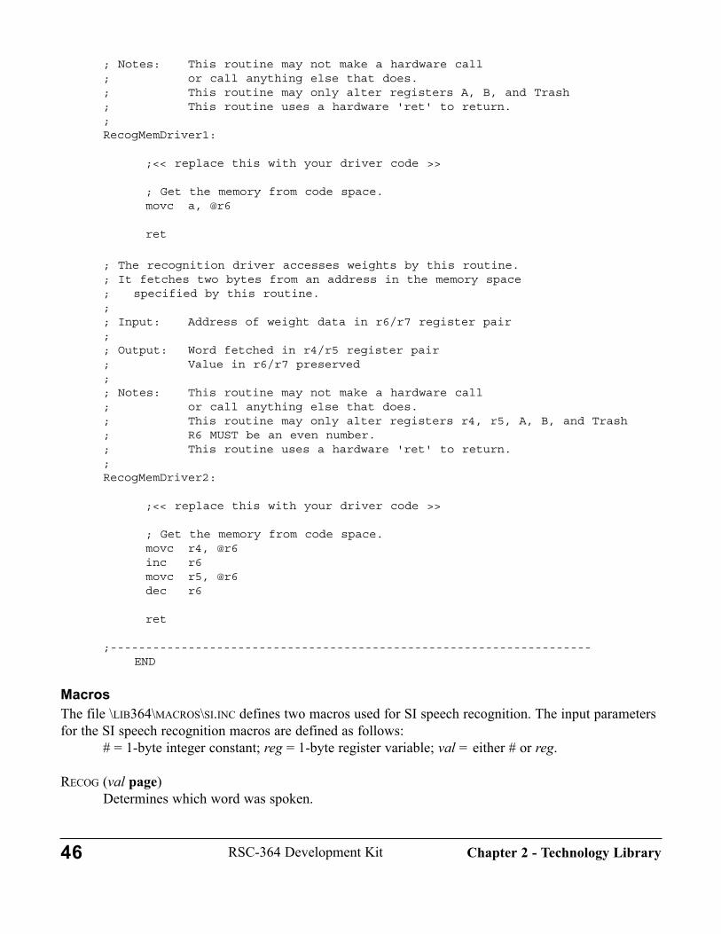
; Notes: This routine may not make a hardware call; or call anything else that does.; This routine may only alter registers A, B, and Trash; This routine uses a hardware 'ret' to return.;RecogMemDriver1:
;<< replace this with your driver code >>
; Get the memory from code space.movc a, @r6
ret
; The recognition driver accesses weights by this routine.; It fetches two bytes from an address in the memory space; specified by this routine.;; Input: Address of weight data in r6/r7 register pair;; Output: Word fetched in r4/r5 register pair; Value in r6/r7 preserved;; Notes: This routine may not make a hardware call; or call anything else that does.; This routine may only alter registers r4, r5, A, B, and Trash; R6 MUST be an even number.; This routine uses a hardware 'ret' to return.;RecogMemDriver2:
;<< replace this with your driver code >>
; Get the memory from code space.movc r4, @r6inc r6movc r5, @r6dec r6
ret
;--------------------------------------------------------------------END
MacrosThe file \LIB364\MACROS\SI.INC defines two macros used for SI speech recognition. The input parametersfor the SI speech recognition macros are defined as follows:
# = 1-byte integer constant; reg = 1-byte register variable; val = either # or reg.
RECOG (val page)Determines which word was spoken.
46 RSC-364 Development Kit Chapter 2 - Technology Library
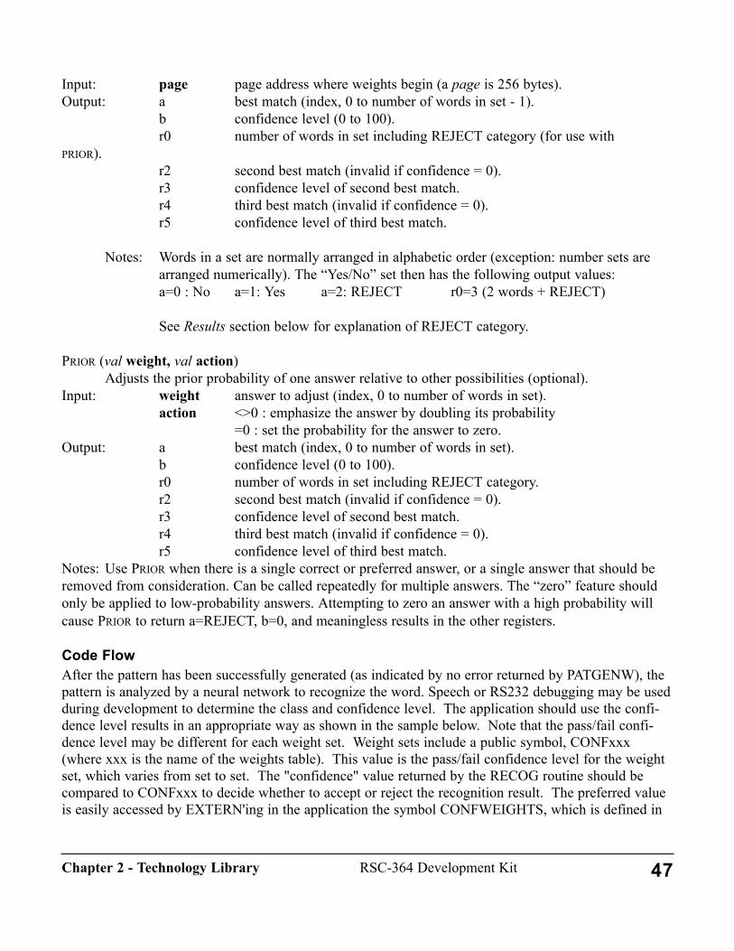
Input: page page address where weights begin (a page is 256 bytes).Output: a best match (index, 0 to number of words in set - 1).
b confidence level (0 to 100).r0 number of words in set including REJECT category (for use with
PRIOR).r2 second best match (invalid if confidence = 0).r3 confidence level of second best match.r4 third best match (invalid if confidence = 0).r5 confidence level of third best match.
Notes: Words in a set are normally arranged in alphabetic order (exception: number sets arearranged numerically). The “Yes/No” set then has the following output values:a=0 : No a=1: Yes a=2: REJECT r0=3 (2 words + REJECT)
See Results section below for explanation of REJECT category.
PRIOR (val weight, val action)Adjusts the prior probability of one answer relative to other possibilities (optional).
Input: weight answer to adjust (index, 0 to number of words in set).action <>0 : emphasize the answer by doubling its probability
=0 : set the probability for the answer to zero.Output: a best match (index, 0 to number of words in set).
b confidence level (0 to 100).r0 number of words in set including REJECT category.r2 second best match (invalid if confidence = 0).r3 confidence level of second best match.r4 third best match (invalid if confidence = 0).r5 confidence level of third best match.
Notes: Use PRIOR when there is a single correct or preferred answer, or a single answer that should beremoved from consideration. Can be called repeatedly for multiple answers. The “zero” feature shouldonly be applied to low-probability answers. Attempting to zero an answer with a high probability willcause PRIOR to return a=REJECT, b=0, and meaningless results in the other registers.
Code FlowAfter the pattern has been successfully generated (as indicated by no error returned by PATGENW), thepattern is analyzed by a neural network to recognize the word. Speech or RS232 debugging may be usedduring development to determine the class and confidence level. The application should use the confi-dence level results in an appropriate way as shown in the sample below. Note that the pass/fail confi-dence level may be different for each weight set. Weight sets include a public symbol, CONFxxx(where xxx is the name of the weights table). This value is the pass/fail confidence level for the weightset, which varies from set to set. The "confidence" value returned by the RECOG routine should becompared to CONFxxx to decide whether to accept or reject the recognition result. The preferred valueis easily accessed by EXTERN'ing in the application the symbol CONFWEIGHTS, which is defined in
47RSC-364 Development KitChapter 2 - Technology Library
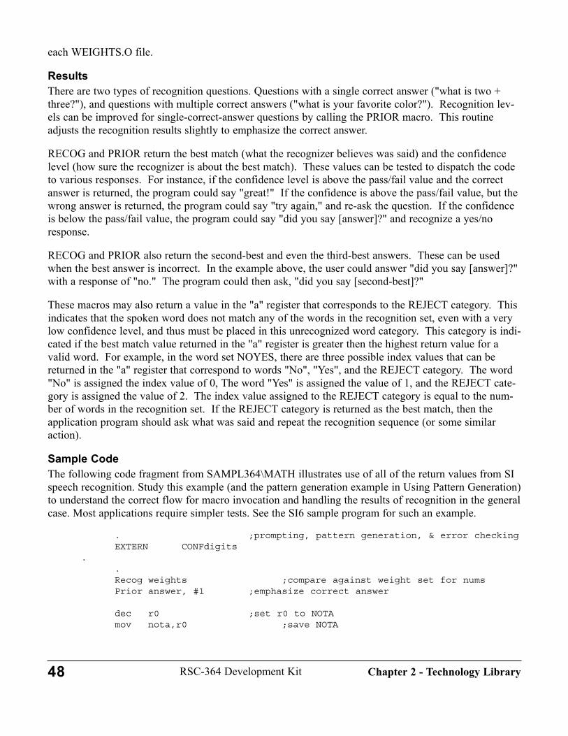
each WEIGHTS.O file.
ResultsThere are two types of recognition questions. Questions with a single correct answer ("what is two +three?"), and questions with multiple correct answers ("what is your favorite color?"). Recognition lev-els can be improved for single-correct-answer questions by calling the PRIOR macro. This routineadjusts the recognition results slightly to emphasize the correct answer.
RECOG and PRIOR return the best match (what the recognizer believes was said) and the confidencelevel (how sure the recognizer is about the best match). These values can be tested to dispatch the codeto various responses. For instance, if the confidence level is above the pass/fail value and the correctanswer is returned, the program could say "great!" If the confidence is above the pass/fail value, but thewrong answer is returned, the program could say "try again," and re-ask the question. If the confidenceis below the pass/fail value, the program could say "did you say [answer]?" and recognize a yes/noresponse.
RECOG and PRIOR also return the second-best and even the third-best answers. These can be usedwhen the best answer is incorrect. In the example above, the user could answer "did you say [answer]?"with a response of "no." The program could then ask, "did you say [second-best]?"
These macros may also return a value in the "a" register that corresponds to the REJECT category. Thisindicates that the spoken word does not match any of the words in the recognition set, even with a verylow confidence level, and thus must be placed in this unrecognized word category. This category is indi-cated if the best match value returned in the "a" register is greater then the highest return value for avalid word. For example, in the word set NOYES, there are three possible index values that can bereturned in the "a" register that correspond to words "No", "Yes", and the REJECT category. The word"No" is assigned the index value of 0, The word "Yes" is assigned the value of 1, and the REJECT cate-gory is assigned the value of 2. The index value assigned to the REJECT category is equal to the num-ber of words in the recognition set. If the REJECT category is returned as the best match, then theapplication program should ask what was said and repeat the recognition sequence (or some similaraction).
Sample CodeThe following code fragment from SAMPL364\MATH illustrates use of all of the return values from SIspeech recognition. Study this example (and the pattern generation example in Using Pattern Generation)to understand the correct flow for macro invocation and handling the results of recognition in the generalcase. Most applications require simpler tests. See the SI6 sample program for such an example.
. ;prompting, pattern generation, & error checkingEXTERN CONFdigits
..Recog weights ;compare against weight set for numsPrior answer, #1 ;emphasize correct answer
dec r0 ;set r0 to NOTAmov nota,r0 ;save NOTA
48 RSC-364 Development Kit Chapter 2 - Technology Library
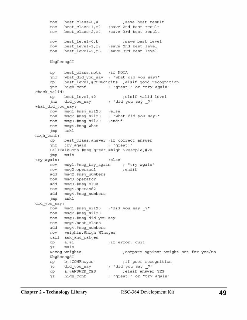
mov best_class+0,a ;save best resultmov best_class+1,r2 ;save 2nd best resultmov best_class+2,r4 ;save 3rd best result
mov best_level+0,b ;save best levelmov best_level+1,r3 ;save 2nd best levelmov best_level+2,r5 ;save 3rd best level
DbgRecogSI
cp best_class,nota ;if NOTAjnc what_did_you_say ; "what did you say?"cp best_level,#CONFdigits ;elsif good recognitionjnc high_conf ; "great!" or "try again"
check_valid:cp best_level,#0 ;elsif valid leveljnz did_you_say ; "did you say _?"
what_did_you_say:mov msg1,#msg_sil20 ;elsemov msg2,#msg_sil20 ; "what did you say?"mov msg3,#msg_sil20 ;endifmov msg4,#msg_whatjmp ask1
high_conf:cp best_class,answer ;if correct answerjnz try_again ; "great!"CallTalkBoth #msg_great,#high VPsample,#VRjmp main
try_again: ;elsemov msg1,#msg_try_again ; "try again"mov msg2,operand1 ;endifadd msg2,#msg_numbersmov msg3,operatoradd msg3,#msg_plusmov msg4,operand2add msg4,#msg_numbersjmp ask1
did_you_say:mov msg1,#msg_sil20 ;"did you say _?"mov msg2,#msg_sil20mov msg3,#msg_did_you_saymov msg4,best_classadd msg4,#msg_numbersmov weights,#high WTnoyescall ask_and_patgencp a,#1 ;if error, quitjz mainRecog weights ;compare against weight set for yes/noDbgRecogSIcp b,#CONFnoyes ;if poor recognitionjc did_you_say ; "did you say _?"cp a,#ANSWER_YES ;elsif answer YESjz high_conf ; "great!" or "try again"
49RSC-364 Development KitChapter 2 - Technology Library
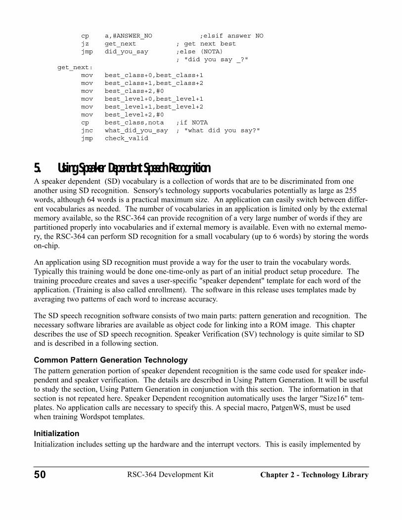
cp a,#ANSWER_NO ;elsif answer NOjz get_next ; get next bestjmp did_you_say ;else (NOTA)
; "did you say _?"get_next:
mov best_class+0,best_class+1mov best_class+1,best_class+2mov best_class+2,#0mov best_level+0,best_level+1mov best_level+1,best_level+2mov best_level+2,#0cp best_class,nota ;if NOTAjnc what_did_you_say ; "what did you say?"jmp check_valid
5. Using Speaker Dependent Speech RecognitionA speaker dependent (SD) vocabulary is a collection of words that are to be discriminated from oneanother using SD recognition. Sensory's technology supports vocabularies potentially as large as 255words, although 64 words is a practical maximum size. An application can easily switch between differ-ent vocabularies as needed. The number of vocabularies in an application is limited only by the externalmemory available, so the RSC-364 can provide recognition of a very large number of words if they arepartitioned properly into vocabularies and if external memory is available. Even with no external memo-ry, the RSC-364 can perform SD recognition for a small vocabulary (up to 6 words) by storing the wordson-chip.
An application using SD recognition must provide a way for the user to train the vocabulary words.Typically this training would be done one-time-only as part of an initial product setup procedure. Thetraining procedure creates and saves a user-specific "speaker dependent" template for each word of theapplication. (Training is also called enrollment). The software in this release uses templates made byaveraging two patterns of each word to increase accuracy.
The SD speech recognition software consists of two main parts: pattern generation and recognition. Thenecessary software libraries are available as object code for linking into a ROM image. This chapterdescribes the use of SD speech recognition. Speaker Verification (SV) technology is quite similar to SDand is described in a following section.
Common Pattern Generation TechnologyThe pattern generation portion of speaker dependent recognition is the same code used for speaker inde-pendent and speaker verification. The details are described in Using Pattern Generation. It will be usefulto study the section, Using Pattern Generation in conjunction with this section. The information in thatsection is not repeated here. Speaker Dependent recognition automatically uses the larger "Size16" tem-plates. No application calls are necessary to specify this. A special macro, PatgenWS, must be usedwhen training Wordspot templates.
InitializationInitialization includes setting up the hardware and the interrupt vectors. This is easily implemented by
50 RSC-364 Development Kit Chapter 2 - Technology Library
linking-in the module \LIB\STARTUP\STARTUP. This module sets the processor speed to oscillator1 1with 1 wait state, and initializes interrupt vectors. This clock state is required for pattern generation. Inaddition, certain I/O configuration must be defined. The module \LIB\STARTUP\CONFIG accomplish-es this task for the standard Development Kit hardware, and can be modified for other designs. SeeSystem Configuration and I/O Mapping under the Software Development tab for more information.
STARTUP jumps to the label INITIALIZE, which should be at the start of the application program andneeds to be PUBLIC'd for linker references.
IncludesThe SD speech recognition routines should be called using macros. LIBINCL the macros defined in\LIB364\MACROS\PATGEN.INC (for pattern generation) and in \LIB364\MACROS\SDSV.INC.
The recognition macros use memory locations that are defined in \LIB\MEMORY\MEMORY.INC, soyou must also LIBINCL this file in the application program. See Using the RSC-364 Memory Map fordetailed information.
Except when using the ON_CHIP option (see the PASSWORD and SPKRVER sample programs),speaker dependent recognition requires external read/write memory for storing templates. (A template ismade by averaging two or more patterns to improve recognition.) The file"\LIB364\SD_SV\XRAM_SDV.INC" must always be included to define the memory co-routine inter-face (see Using Co-Routines for External Memory Access).
LinkingLink the application code with the initialization module \LIB\STARTUP\STARTUP, the math module\LIB364\UTIL\INTMATH, the configuration module \LIB\STARTUP\CONFIG, and the pattern genera-tion modules BLOCK, NORMAL, NULOGFNS, PATGEN, DIGAGC, STREAM, and PATGEN_H in\LIB364\PATGEN . Next, link in the SD recognition modules, SD.O, SDWEIGHTS.O, and TEM-PLATE.O from \LIB364\SD_SV\. In special cases a different version of SDWEIGHTS.O may be sub-stituted for specific applications such as recognition over telephone lines.
Finally link in one of the external memory co-routine modules such as SRAM_SDV.O (or your replace-ment) and any other memory access, technology, or application modules you use. To use the WORDSON CHIP option, link in \LIB364\SD_SV\ONCHIP.O as the on-chip memory handler, and also link\LIB364\SD_SV\AUXTMPLT.O, the auxiliary template handler.
Pattern Memory UsagePatterns and templates in the RSC-364 may be stored in external memory, or may temporarily reside inone or more of four areas within the 364 chip. The technology software identifies these four areas as:#TMPLT_UNKNOWN - This is the area where Patgen places the new pattern.#TMPLT_KNOWN - Typically used for retrieving a template from external memory.#TMPLT_MODIFIED - May be used to hold a second pattern or average of two patterns.#TMPLT_WS - This area is used by Wordspot to hold the template being spotted.
Except for Patgen and Wordspot, usage of these areas is determined by the application program throughuse of the macros described below. An additional template storage area is provided for use by theON_CHIP feature. This feature allows storing up to four WS templates on chip when no external tem-
51RSC-364 Development KitChapter 2 - Technology Library
plate storage is used. See Using On-Chip Template Storage in Chapter 3, for details.
NOTE: in this release, TMPLT_MODIFIED and TMPLT_WS are the same physical area. Applicationuse of this area limits on-chip template storage to 4 templates.
Except for Patgen and Wordspot, usage of these areas is determined by the application program throughuse of the macros described below. An additional template storage area is provided for use by theON_CHIP feature. This feature allows storing up to six SD templates on chip when no external tem-plate storage is used. See Using On-Chip Template Storage in Chapter 3, for details.
To conserve storage space, the template management routine compresses the template data before storingit, and decompresses it when retrieving. The template size information (10 or 16) is also stored with thetemplate data.
MacrosThe Speaker Dependent/Speaker Verification recognition module contains six macros: two for templatetransfer, and one each for training and recognition for SD and SV. The SV macros are described in theSpeaker Verification section. Of the four macros used by SD, three are for training and one is for recog-nition.
The speaker dependent input parameters are defined as follows: # = 1-byte integer constant; reg = 1-byte register variable; val = either # or reg.
PUTTMPLT ( val tmpltX) [TRAINING]Saves a template (pattern) from a specific area in technology RAM to external memory.Input: tmpltX Identifier of one of three areas where the template can be
located in the RSC-264T memory. Output: None
Notes: Requires external memory handler at location put_byte_sdv.Memory handler must set up memory initialization before invoking PUTTMPLT. The parameter tmpltX can have the following system-defined values:#TmPLT_UNKNOWN - usually the most recent patgen pattern#TMPLT_KNOWN - typically an older pattern from external memory#TMPLT_MODIFIED - typically an averaged pattern#TMPLT_WS - This area is used by Wordspot
GETTMPLT ( val tmpltX) [TRAINING]Retrieves a template (pattern) from external memory into a specific area in
technology RAM.Input: tmpltX Identifier of one of three areas where the template can be
located in the RSC-264T memory.Output: None
Notes: Requires external memory handler at location get_byte_sdv. Memory handler must set up memory initialization before invoking GETTMPLT. The parameter tmpltX can have the following values:#TMPLT_UNKNOWN - usually the most recent patgen pattern
52 RSC-364 Development Kit Chapter 2 - Technology Library
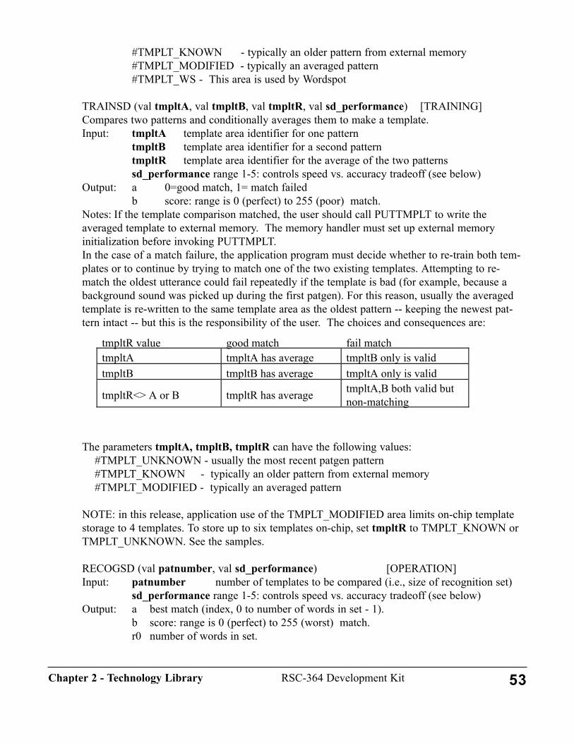
#TMPLT_KNOWN - typically an older pattern from external memory#TMPLT_MODIFIED - typically an averaged pattern#TMPLT_WS - This area is used by Wordspot
TRAINSD (val tmpltA, val tmpltB, val tmpltR, val sd_performance) [TRAINING]Compares two patterns and conditionally averages them to make a template.Input: tmpltA template area identifier for one pattern
tmpltB template area identifier for a second patterntmpltR template area identifier for the average of the two patternssd_performance range 1-5: controls speed vs. accuracy tradeoff (see below)
Output: a 0=good match, 1= match failedb score: range is 0 (perfect) to 255 (poor) match.
Notes: If the template comparison matched, the user should call PUTTMPLT to write the averaged template to external memory. The memory handler must set up external memory initialization before invoking PUTTMPLT. In the case of a match failure, the application program must decide whether to re-train both tem-plates or to continue by trying to match one of the two existing templates. Attempting to re-match the oldest utterance could fail repeatedly if the template is bad (for example, because abackground sound was picked up during the first patgen). For this reason, usually the averagedtemplate is re-written to the same template area as the oldest pattern -- keeping the newest pat-tern intact -- but this is the responsibility of the user. The choices and consequences are:
The parameters tmpltA, tmpltB, tmpltR can have the following values:#TMPLT_UNKNOWN - usually the most recent patgen pattern#TMPLT_KNOWN - typically an older pattern from external memory#TMPLT_MODIFIED - typically an averaged pattern
NOTE: in this release, application use of the TMPLT_MODIFIED area limits on-chip templatestorage to 4 templates. To store up to six templates on-chip, set tmpltR to TMPLT_KNOWN orTMPLT_UNKNOWN. See the samples.
RECOGSD (val patnumber, val sd_performance) [OPERATION]Input: patnumber number of templates to be compared (i.e., size of recognition set)
sd_performance range 1-5: controls speed vs. accuracy tradeoff (see below)Output: a best match (index, 0 to number of words in set - 1).
b score: range is 0 (perfect) to 255 (worst) match.r0 number of words in set.
tmpltR value good match fail matchtmpltA tmpltA has average tmpltB only is validtmpltB tmpltB has average tmpltA only is valid
tmpltR<> A or B tmpltR has average tmpltA,B both valid butnon-matching
53RSC-364 Development KitChapter 2 - Technology Library

r1 result: 0=pass; 1=fail (based on best score), 2=uncertainr2 2nd best match (index as for "a")r3 2nd-best score (range as for "b")r4 (r2-b) = difference between two best scores.
Notes: Requires external memory handler at location get_byte_sdv.Requires external template validation handler at validate_template_sdv. No match is indicated if a=r0.Physical limit of patnumber is 255, but less than 64 gives better recognition. r1=2 (uncertain) return indicates that more than one template produces a good match.
Score may be of help in deciding if a new vocabulary word is too close to an existing word (see below).
Additional ParametersThe RecogSD macro uses the following parameters to control operation characteristics. Default valuesare defined in \LIB364\MACROS\SD_SV.INC, but the user may redefine these values in an applicationprogram by using the SET directive.
The parameter SD_PERFORMANCE controls convenience/speed/accuracy tradeoffs in SD recognition.Set it to 1 if you want the fastest and easiest possible response; set it to 5 for the highest accuracy withstrict pronounciation constraints. Although the recognition time for SD in Version 6 is somewhat fasterthan in previous releases, the value of SD_PERFORMANCE still has a strong influence over the totalrecognition time. This value may be set from 1 to 5 (inclusive), with the default value of 3 giving therecommended compromise between speed and accuracy. For SD sets larger than 5 words, the executiontime in milliseconds is approximately given by
Te = 2+ 3*n+ 30*SDPwhere n = number of templates in the set and SDP = 1,3,3,5,5 for SD_PERFORMANCE = 1,2,3,4,5.
This formula shows that a small, 5-entry set can be recognized in less than 50 msec with SD_perform-ance set to 1. Conversely, recognition from a large 64-word set with SD_performance equal to 5 requiresabout one-third second. Very little degradation in accuracy occurs in reducing SDP from 5 to 2, butaccuracy does decrease somewhat for SDP = 1. Note: recognition times above are based on flash storageof templates. Slower memories such as Serial EEPROM will increase the recognition time.
The parameter SD_WEIGHTS is normally taken to be the library default, suitable for generic electretmicrophones. Special SD weight sets may be needed for particular environments such as over-the-tele-phone.
Training Code FlowAs explained above, the application should be divided into a training phase and a normal operationphase. Each time a pattern is produced, the appropriate pattern generation macros must be called asdescribed in Using Pattern Generation. After the first pattern has been generated during training, it isstored to external memory using PUTTMPLT. This step is necessary because there is normally insuffi-cient space in the RSC-364 RAM to store the original pattern while generating the comparison pattern.The technology code manages an area of RSC-364 RAM for temporary storage of a second pattern dur-
54 RSC-364 Development Kit Chapter 2 - Technology Library
ing comparisons, but this area is used by the PATGEN macro. When the WORDS ON CHIP option isused, a special version of PUTTMPLT saves the first pattern internally in a temporary location.
A second pattern is generated and the two patterns are compared. If they match well enough, the patternsare averaged and the resulting template is written to external memory. If the patterns do not match wellenough, the application should require another patgen. See the discussion at the description ofTRAINSD above for considerations about training failures.
The next important step is to check that the new template is sufficiently different from the other tem-plates in the vocabulary. Similar words should be avoided in order to keep the recognition rate high.After the new template has been trained, but before including it in the vocabulary, recognize the aver-aged pattern against the existing vocabulary and reject the word if it matches too closely to an existingword. This topic is discussed in more detail below.
This process is repeated for each word in each vocabulary. When all the words have been trained, thevocabulary can be used for recognition.
Recognition Code Flow and ResultsTo recognize a word the pattern is generated as described elsewhere. If the pattern generation softwarereturns no error, the RECOGSD macro is then called. During execution of the RECOGSD macro everytemplate of the vocabulary is read at least once-some templates may be read multiple times. Templatesin the RSC-364 are stored externally in compressed form occupying up to 128 bytes (the actual numberof bytes depends on whether the template size is set to 10 or 16). The RECOGSD macro callsget_byte_sdv as many as 128 times for each of the patnumber templates, and there may be additionalsystem reads as well, so many external memory accesses are required for each recognition using a largevocabulary. The memory co-routine is responsible for determining the proper memory address of eachbyte, and for switching to a new pattern when necessary as illustrated in the code samples. See alsoUsing Co-Routines for External Memory Access.
A match criterion is calculated for each of the patnumber templates. The RECOGSD macro returns anindex in the "a" register that indicates the closest match and an index in the "r2" register that indicatesthe second-closest match. If there is no match, "a" will be returned with the same value as "r0" and the"r1" register will be non-zero. A RecogSD match can fail if no template gives a good match (r1=1), orif multiple templates give good matches (r1=2).
The "b" register contains the score, a distance measure of the fit of the unknown pattern to the closestmatching template. The lower the score, the better the match. The score for the second-closest match isreturned in the "r3" register. These scores can be used to assure that new vocabulary words are not toosimilar to existing words. For example, the words "Composition" and "Competition" sound enoughalike that it may not be wise to use both words in a single SD recognition vocabulary. To detect the sim-ilarity between a newly trained word and an existing word, call RECOGSD immediately after calling theTRAINSD macro. (No calls to synthesis or other technologies may intervene or the pattern may be dis-turbed.) Each macro will return a score in "b". The score from TRAINSD indicates how closely thetwo utterances (presumably of the new word) matched, while the score returned by RECOGSD indicateshow well the averaged template matches the closest other vocabulary word. If these two scores areclose, the speaker should be instructed to choose a different word. As a rule of thumb, the RECOGSDscore should be at least 12 more than the score from TRAINSD. See the SPKRDEP sample for an exam-
55RSC-364 Development KitChapter 2 - Technology Library
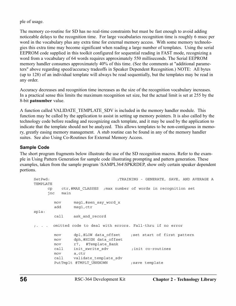
ple of usage.
The memory co-routine for SD has no real-time constraints but must be fast enough to avoid addingnoticeable delays to the recognition time. For large vocabularies recognition time is roughly 6 msec perword in the vocabulary plus any extra time for external memory access. With some memory technolo-gies this extra time may become significant when reading a large number of templates. Using the serialEEPROM code supplied in this toolkit configured for sequential reading in FAST mode, recognizing aword from a vocabulary of 64 words requires approximately 550 milliseconds. The Serial EEPROMmemory handler consumes approximately 40% of this time. (See the comments at "additional parame-ters" above regarding speed/accuracy tradeoffs in Speaker Dependent Recognition.) NOTE: All bytes(up to 128) of an individual template will always be read sequentially, but the templates may be read inany order.
Accuracy decreases and recognition time increases as the size of the recognition vocabulary increases.In a practical sense this limits the maximum recognition set size, but the actual limit is set at 255 by the8-bit patnumber value.
A function called VALIDATE_TEMPLATE_SDV is included in the memory handler module. Thisfunction may be called by the application to assist in setting up memory pointers. It is also called by thetechnology code before reading and recognizing each template, and it may be used by the application toindicate that the template should not be analyzed. This allows templates to be non-contiguous in memo-ry, greatly easing memory management. A stub routine can be found in any of the memory handlersuites. See also Using Co-Routines for External Memory Access.
Sample CodeThe short program fragments below illustrate the use of the SD recognition macros. Refer to the exam-ple in Using Pattern Generation for sample code illustrating prompting and pattern generation. Theseexamples, taken from the sample program \SAMPL364\SPKRDEP, show only certain speaker dependentportions.
SetPwd: ;TRAINING - GENERATE, SAVE, AND AVERAGE ATEMPLATE
cp ctr,#MAX_CLASSES ;max number of words in recognition setjnc main
mov msg1,#sen_say_word_xadd msg1,ctr
sp1a:call ask_and_record
;. . . omitted code to deal with errors. Fall-thru if no error
mov dpl,#LOW data_offset ;set start of first patternmov dph,#HIGH data_offsetmov r7, #Template_Bankcall init_xwrite_sdv ;init co-routinesmov a,ctrcall validate_template_sdvPutTmplt #TMPLT_UNKNOWN ;save template
56 RSC-364 Development Kit Chapter 2 - Technology Library

call exit_xwrite_sdv ;finish up co-routines; fall into confirmSetPwdCnfrm:
mov msg1,#sen_repeatcall ask_and_recordcp a,#0jnz SetPwdError ;error
mov dpl,#LOW data_offset ;set start of first patternmov dph,#HIGH data_offsetmov r7, #Template_Bank
call init_xread_sdv ;init co-routinesmov a,ctrcall validate_template_sdvGetTmplt #TMPLT_KNOWN ;get first templatecall exit_xread_sdv ;finish up co-routines
; Note: We use TMPLT_UNKNOWN as a trainSD target (rather then TMPLT_MODIFIED); because this is convenient for the 'too similar' test below.
TrainSD #TMPLT_UNKNOWN,#TMPLT_KNOWN,#TMPLT_UNKNOWN ;average tem-plates
cp a,#0jz TrainPassjmp SetPwdFail
SetPwdError:;code to deal with error
TrainPass:
;OMITTED CODE TO CHECK FOR "TOO SIMILAR" BEFORE INCLUDING IN VOCABULARY****see sample program
mov dpl,#LOW data_offset ;set start of first patternmov dph,#HIGH data_offsetmov r7, #Template_Bank
call init_xwrite_sdv ;init co-routinesmov a,ctrcall validate_template_sdvPutTmplt #TMPLT_unknown ;save templatecall exit_xwrite_sdv ;finish up co-routines
;-----------
AskPwd: ;recognition fragmentmov msg1,#sen_say_a_wordcall ask_and_recordcp a,#0jnz AskPwdError ;patgen error
57RSC-364 Development KitChapter 2 - Technology Library
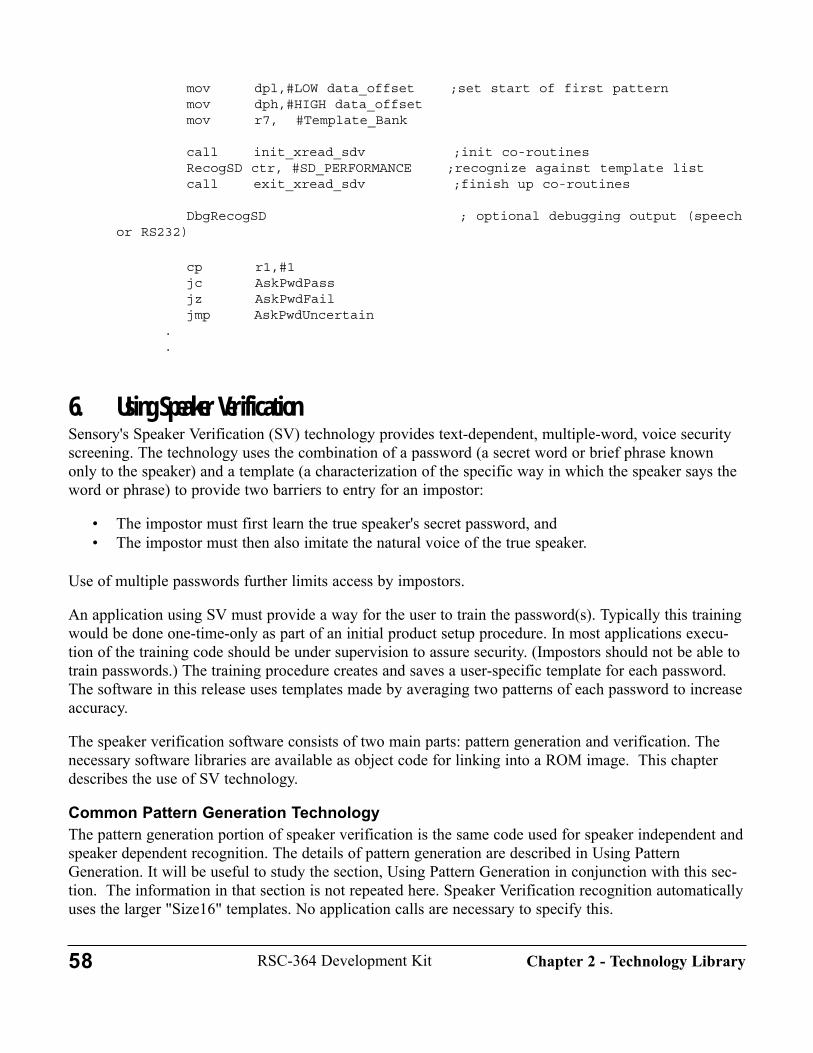
mov dpl,#LOW data_offset ;set start of first patternmov dph,#HIGH data_offsetmov r7, #Template_Bank
call init_xread_sdv ;init co-routinesRecogSD ctr, #SD_PERFORMANCE ;recognize against template listcall exit_xread_sdv ;finish up co-routines
DbgRecogSD ; optional debugging output (speechor RS232)
cp r1,#1jc AskPwdPassjz AskPwdFailjmp AskPwdUncertain
.
.
6. Using Speaker VerificationSensory's Speaker Verification (SV) technology provides text-dependent, multiple-word, voice securityscreening. The technology uses the combination of a password (a secret word or brief phrase knownonly to the speaker) and a template (a characterization of the specific way in which the speaker says theword or phrase) to provide two barriers to entry for an impostor:
• The impostor must first learn the true speaker's secret password, and • The impostor must then also imitate the natural voice of the true speaker.
Use of multiple passwords further limits access by impostors.
An application using SV must provide a way for the user to train the password(s). Typically this trainingwould be done one-time-only as part of an initial product setup procedure. In most applications execu-tion of the training code should be under supervision to assure security. (Impostors should not be able totrain passwords.) The training procedure creates and saves a user-specific template for each password.The software in this release uses templates made by averaging two patterns of each password to increaseaccuracy.
The speaker verification software consists of two main parts: pattern generation and verification. Thenecessary software libraries are available as object code for linking into a ROM image. This chapterdescribes the use of SV technology.
Common Pattern Generation TechnologyThe pattern generation portion of speaker verification is the same code used for speaker independent andspeaker dependent recognition. The details of pattern generation are described in Using PatternGeneration. It will be useful to study the section, Using Pattern Generation in conjunction with this sec-tion. The information in that section is not repeated here. Speaker Verification recognition automaticallyuses the larger "Size16" templates. No application calls are necessary to specify this.
58 RSC-364 Development Kit Chapter 2 - Technology Library
Comparison with Speaker Dependent Speech RecognitionSpeaker verification is a special variation of speaker dependent recognition. The main conceptual differ-ence is that SD recognition attempts to ignore differences in the way a given word is spoken by differentspeakers, while the SV recognition attempts to detect such individual differences. Another difference isthe typical vocabulary size: SD may often be 30, 40, or more words, but a multiple-word password has amaximum length of four words. Speaker verification applications typically may screen many users, butan SD application is usually trained for a single user. Apart from these differences, the two technologiesshare the need for external non-volatile read-write memory, memory co-routine handlers, and separationof the application into training and operational phases. It will be useful to study Using SpeakerDependent Speech Recognition in conjunction with this section. The option of ON_CHIP allows theRSC-364 to store a single password sequence without needing any external memory.
Note that Sensory's SV technology is Speaker Verification, not Speaker Identification. In verification,the identity of the user is already known. A limited form of Speaker Identification is available, however.Due to the memory requirements of the algorithms, a maximum of five different speakers can be testedin a single SV recognition attempt. Further, because of memory limitations, the identification must bemade based only on the first password and not the entire sequence. An application could use SV technol-ogy alone to identify and verify a user based only on the password sequence if the total number of userswas five or fewer. However, an application that needs to voice-identify one user from a group larger thanfive users would need to use SD recognition (on the first utterance) to identify the best sub-group offive, then SV to verify from that sub-group. Alternatively users could be placed into sub-groups of fiveduring training, then during operation the utterance would be recognized against each of the sub-groupswith SV. Both approaches require careful use of template memory management to assure that the correctnext template is provided to the recognizer.
Note also that the meaning of "next template" might vary within the application. For example, assumefour users have each trained 3-word passwords, and the first user's first password has just been providedto the recognition routine. Then the "next template" would be the first user's second password whendoing Speaker Verification, but would be the first template of the second user when doing SpeakerIdentification (testing each user's first template for the best match to the unknown pattern). A local vari-able may be used by the application to signal which of these two memory arrangements is to be used bythe memory co-routine, validate_template_sdv. The Speaker Verification code can accommodate a maxi-mum of five users in this way for Speaker Identification.
The speaker verification macros parallel those of SD, but they are given different names because theyinvoke different underlying technology code and may return different values. The speaker dependentmacros are named XXXXSD, and the corresponding speaker verification macros are named XXXXSV.The template manipulation macros are identical for both technologies.
InitializationInitialization is identical to speaker dependent. The SD_PERFORMANCE parameter does not effectspeaker verification.
IncludesThe SV routines should be called using macros. LIBINCL the macros defined in\LIB364\MACROS\PATGEN.INC (for pattern generation) and in \LIB364\MACROS\SDSV.INC.
59RSC-364 Development KitChapter 2 - Technology Library
The recognition macros use memory locations that are defined in \LIB\MEMORY\MEMORY.INC, soyou must also LIBINCL this file in the application program. See Using the RSC-364 Memory Map fordetailed information.
Except when using the ON_CHIP option (see the SPKRVER sample program), speaker verificationrequires external read/write memory for storing templates. (A template is made by averaging two ormore patterns to improve recognition.) The file "\LIB364\SD_SV\XRAM_SDV.INC" must be includedto define the external memory co-routine interface (see Using Co-Routines for External MemoryAccess).
LinkingLink the application code with the initialization module \LIB\STARTUP\STARTUP, the math module\LIB364\UTIL\INTMATH, the configuration module \LIB\STARTUP\CONFIG, and the pattern genera-tion modules BLOCK, NORMAL, NULOGFNS, STREAM, PATGEN, DIGAGC, and PATGEN_H in\LIB364\PATGEN. Next, link in the SV recognition modules, SV.O, SVWEIGHT.O, and TEM-PLATE.O from \LIB364\SD_SV\. Speaker Verification uses some SD code, so you must also link\LIB364\SD_SV\SD.O. Finally link in one of the external memory co-routine modules such asSRAM_SDV.O (or your replacement) and any other memory access, technology, or application modulesyou use. To use the WORDS_ON_CHIP option, link in \LIB364\SD_SV\ONCHIP.O as the on-chipmemory handler, and also link \LIB364\SD_SV\AUXTMPLT.O, the auxiliary template handler.
Pattern Memory UsagePatterns and templates in the RSC-364 may be stored in external memory, or may temporarily reside inone or more of four areas within the 364 chip. These four areas are identified by the technology softwareas:
#TMPLT_UNKNOWN - This is the area where Patgen places the new pattern.#TMPLT_KNOWN - Typically used for retrieving a template from external memory.#TMPLT_MODIFIED - May be used to hold a second pattern or average of two patterns.#TMPLT_WS - This area is used by Wordspot to hold the template being spotted.
Except for Patgen and Wordspot, usage of these areas is determined by the application program throughuse of the macros described below. An additional template storage area is provided for use by theON_CHIP feature. This feature allows storing one 4-word SV sequence of templates on chip when noexternal template storage is used. See Using On-Chip Template Storage in Chapter 3, for details.
NOTE: in this release, TMPLT_MODIFIED and TMPLT_WS are the same physical area. Applicationuse of this area limits on-chip template storage to 4 templates.
To conserve storage space, the template management routine compresses the template data before storingit, and decompresses it when retrieving. The template size information (10 or 16) is also stored with thetemplate data.
MacrosSpeaker Dependent/Speaker Verification recognition module contains 6 macros, two for template trans-
60 RSC-364 Development Kit Chapter 2 - Technology Library
fer, and one each for training and recognition for SD and SV. The SD macros are described in theSpeaker Dependent section. Of the 4 macros used by SV, three are for training and one is for operation.
The speaker verification input parameters are defined as follows: # = 1-byte integer constant; reg = 1-byte register variable; val = either # or reg.
PUTTMPLT ( val tmpltX) [TRAINING]Saves a template (pattern) from a specific area in technology RAM to external memory.Input: tmpltX Identifier of one of three areas where the template can be
located in the RSC-364 memory. Output: NoneNotes: Requires external memory handler at location put_byte_sdv.Memory handler must set up memory initialization before invoking PUTTMPLT. The parameter tmpltX can have the following system-defined values:
#TmPLT_UNKNOWN - usually the most recent patgen pattern#TMPLT_KNOWN - typically an older pattern from external memory#TMPLT_MODIFIED - typically an averaged pattern
GETTMPLT ( val tmpltX) [TRAINING]Retrieves a template (pattern) from external memory into a specific area in technology RAM.Input: tmpltX Identifier of one of three areas where the template can be
located in the RSC-364 memory.Output: NoneNotes: Requires external memory handler at location get_byte_sdv.
Memory handler must set up memory initialization before invoking GETTMPLT. The parameter tmpltX can have the following values:
#TMPLT_UNKNOWN - usually the most recent patgen pattern#TMPLT_KNOWN - typically an older pattern from external memory#TMPLT_MODIFIED - typically an averaged pattern
TRAINSV (val tmpltA, val tmpltB, val tmpltR, sd_performance)[TRAINING]Compares two patterns and conditionally averages them to make a template.Input: tmpltA template area identifier for one pattern
tmpltB template area identifier for a second patterntmpltR template area identifier for the average of the two patternssd_performance range 1-5: controls speed vs. accuracy tradeoff (see above)
Output: a 0=good match, 1= match failedb score: range is 0 (perfect) to 255 (poor) match.
Notes: If the template comparison matched, the user should call PUTTMPLT to write the aver-aged template to external memory. The memory handler must set up external memory initializa-tion before invoking PUTTMPLT. In the case of a match failure, the application program must decide whether to re-train both tem-
61RSC-364 Development KitChapter 2 - Technology Library

plates or to continue by trying to match one of the two existing templates. Usually the averagedtemplate is re-written to the same template area as the oldest template, but this is the responsibili-ty of the user. See the discussion at TrainSD above. The parameters tmpltA, tmpltB, tmpltR can have the following values:
#TMPLT_UNKNOWN - usually the most recent patgen pattern#TMPLT_KNOWN - typically an older pattern from external memory#TMPLT_MODIFIED - typically an averaged pattern
The score returned in "b" is similar to the score returned by RECOGSD, but is different from the com-posite score returned by RECOGSV, below.
RECOGSV (val word, val size, val sec_level, val num_tmplts) [OPERATION]Recognizes a password sequence spoken by a single user.Input: word word number in sequence (1...size)
size number of words in sequence (1,2,3, or 4)sec_level security level (0,1,...5) [see notes]num_tmplts number of templates in external memory to test (1,...)
Output: a sequence decision: 0 = pass; 1 = fail; FF = undecidedb current word: 0 = pass; 1 = failr7 best class (if r7=num_tmplts then error)r6 current composite score (0=bad, 255=good)
Notes: Requires external memory handler at location get_byte_sdv.The value returned in "score" is significantly different from the score returned by the TRAINSV macro.
Unlike Speaker Dependent, SV makes a pass/fail decision on each utterance and never returns an"undecided" result for the current word (b).
Expanded RECOGSV Macro NotesThis macro offers a variety of configurations for SV recognition. By setting size appropriately, as manyas four passwords may be verified sequentially. The sec_level parameter controls the security level,which is used by the verifier to make a decision regarding a match. All speaker verification systems aresubject to two types of errors: a False Accept (FA), in which an impostor is allowed access, and a FalseReject (FR), in which the true speaker is prevented access. The relative importance of each kind of errordepends on the application. In general, the security level controls the tradeoff between FA and FRerrors, while using multiple passwords may reduce both kinds of errors. The default (intermediate)security level is designed to produce "equal error rates" (FA=FR) with any selected number of pass-words. Higher values of sec_level decrease the FA rate at the cost of increased FRs (acceptance moredifficult). Lower values of sec_level make acceptance easier.
The special value of zero (0) for sec_level forces SV into a special mode appropriate for ContinuousListening applications. This value causes the size parameter to be forced to one (1) regardless of thevalue passed. It also causes SV to use a special "extra low" security level that is more appropriate formost CL applications. Other sec_level values may be used with CL at the programmer's discretion.NOTE: To reduce false triggering, the CLSV word should be used as a "wakeup" word, and should notbe used to invoke actions. See Continuous Listening below.
62 RSC-364 Development Kit Chapter 2 - Technology Library

Enforcement of a strict sequence for a multi-word password is accomplished by setting num_tmplts to 1.This forces a match to a single template. Setting num_tmplts to size permits any of the user's passwordsto be spoken at each utterance time. The memory co-routine must be aware of the ownership and posi-tion-in-sequence of all templates in order to supply the correct templates. See the sample code belowand in the \MEMORY\SRAM\SD_SV, \MEMORY\SEEPROM\SD_SV, and\MEMORY\FLASH\SD_SV directories. A Speaker Verification application knows the identity of thespeaker before the password is spoken, so it is only necessary to test those templates owned by theclaimed speaker. The code may also be used in a Speaker Identification mode by testing the pattern ofthe first utterance against all stored passwords if the number of users is five or fewer. See the commentsat "Comparison with Speaker Dependent Speech Recognition" above.
The macro returns a "sequence decision" in register A after each word is verified. Several words may berequired before a "pass" or "fail" is returned because the algorithm computes a composite score based onall the words. The "sequence undecided" value is returned until the sequence pass/fail decision can bemade. Good security design would typically require the user to speak all of the passwords (maximum offour) before making the decision known, even if a decision is available earlier. Use of the sequencedecision return value allows the application designer to employ "early accept" and/or "early reject" ifdesired. The designer may also want to reject a sequence if any one of the words would fail on its own.This may be accomplished by using the "current word" status returned in register B. The value ofsec_level for an entire sequence is fixed by the value passed on the call for the first word.
Note: The composite score returned in the "score" register is significantly different from the scorereturned by the corresponding SD macro, RECOGSD, or by the TRAINSV macro.
Training Code FlowThe overall flow for SV is very similar to SD, consisting of separate training and operation phases. Seethe "Training Code Flow" chapter of Using Speaker Dependent Speech Recognition, which is generallythe same for SV.
Recognition Code Flow and ResultsTo recognize a word, the pattern is generated as described in Using Pattern Generation. If the patterngeneration software returns no error, the RECOGSV macro is then called. During execution ofRECOGSV, password templates are read as specified in the calling parameters. Each template is 128bytes. The RECOGSV macro CALLS to get_byte_sdv 128 times for each of the num_tmplts being test-ed, and there may be additional system reads as well, so many external memory accesses may berequired. The memory co-routine is responsible for determining the proper memory address of eachbyte, and for switching to a new template when necessary, as illustrated in the samples.
Recognition time for speaker verification is substantially slower than speaker dependent-roughly 30msec per template plus any extra time for external memory access. Recognition time is generally not anissue, since a true SV application needs to test only a few templates for each word recording.
Sample CodeThe following short program fragment illustrates the use of the SV recognition macro in a multi-wordapplication. Refer to the example in Using Pattern Generation for sample code illustrating prompting andpattern generation. The only difference between the training sequence for SD and SV is the names of the
63RSC-364 Development KitChapter 2 - Technology Library

macros, so please refer to the "Sample Code" section, TRAINING of section 5, Using SpeakerDependent Speech Recognition for that sample. The sample below, taken from the SAMPL364\SPKRV-ER sample, illustrates only the verification phase of multi-word speaker verification. If a single pass-word is used, recognition flow is similar to Speaker Dependent. A more sophisticated application wouldset flags for conditions like EARLY_EXIT or EXIT_1_FAIL, and would not announce failure until afterthe user speaks the entire sequence. See the PASSWORD demo for a simple single-word SV application.
The RecogSV macro returns the "best class" in register r7. Normally this value is not needed. If it isneeded, be sure to save it before invoking exit_xread_sdv, as this call overwrites r7.
AskPwd: ;VERIFICATION - VERIFY A PASSWORD STRING mov word,#0 ;first word of sequenceAskPwd1:
cp word,ctr ;if all words recognizedjnc AskPwdTst ; test final decision
mov msg1,#sen_say_x_pwd ;prompt message "please say your <nth>password"
add msg1, wordcall ask_and_record ;prompt and create templatecp a,#0jnz AskPwdError ;error (bad pattern)
IF SEQ_RANDOM ;SEQ_RANDOM<>0: ALLOWS RANDOM SEQUENCE OFPASSWORDS
mov dpl,#LOW tmplt0 ;set start of first patternmov dph,#HIGH tmplt0call init_xread_sdv ;init co-routinesmov trash,wordinc trashRecogSV trash,ctr,acc_level,ctr ;recognize against all templates
ELSE ;SEQ_RANDOM=0: ENFORCE STRICT SEQUENCE OF PASS-WORDS
mov dph,word ;calc offset for wordmov dpl,#0 ; ** (for this sample, templates are
placed)shr dph ; ** (on 128 byte boundaries for simplicity)rrc dpl ; ** (in calculating addresses)add dpl,#LOW tmplt0 ;set start of specific patternadc dph,#HIGH tmplt0call init_xread_sdv ;init co-routinesmov trash,wordinc trashRecogSV trash,ctr,acc_level,#1 ;recognize against specific tem-
plateENDIF
call exit_xread_sdv ;finish up co-routines
IF EARLY_EXIT ;EARLY_EXIT<>0: ALLOWS STOPPING BEFORE ctrWORDS
64 RSC-364 Development Kit Chapter 2 - Technology Library
cp a,#0FFhjnz AskPwdTst ;exit if pass or fail
ENDIF ;EARLY_EXIT=0: FORCE ALL WORDS TO BE SPOKEN
IF EXIT_1_FAIL ;EXIT_1_FAIL<>0: FAILS IF ANY ONE WORDFAILS
cp b,#1jz AskPwdFail ;exit if any single word fails
ENDIF ;EXIT_1_FAIL=0: ALLOW PASS EVEN IF ONE WORDFAILS
inc wordjmp AskPwd1
AskPwdTst: ;test final pass/fail decisioncp a,#1jc AskPwdPass ;acceptedjz AskPwdFail ;rejectedjmp AskPwdError ;undecided..
.
7. Using Continuous ListeningContinuous Listening (CL) is a variation of Sensory's speech recognition technology that provides thecapability to listen continuously for a "trigger" word or phrase to be spoken. Continuous Listening issuitable for use in Speaker Independent/Speaker Dependent/Speaker Verification applications. This tech-nology was previously referred to as "CL4". In addition to CL, release 6 supports Wordspotting (WS),which may be used with Speaker Dependent only.
Continuous Listening has been significantly improved and simplified in release 6 by incorporation ofspeech framing technology. In the discussion below, the term "word" is used in the strict sense, but alsoin the general sense of an utterance -- to include individual words as well as brief phrases.
Comparison of CL and WSSensory supports two different methods of recognizing unprompted utterances. This section comparesand contrasts the two methods. It should help identify the appropriate method for a given application.
In CL applications, a word (or multi-word sequence) is spoken with pauses surrounding each word. Forexample, the phrase "place quick call" is spoken as "<pause>place <pause> quick <pause> call<pause>".Each word is separately recognized, but the speaker must intentionally create the separations betweenwords. Because each word is independently recognized, this CL method can be used with either SI orSD/SV. The recognition is unconstrained, so each word could be recognized from a set of SI or SDwords. That is, CL can listen for several utterances in parallel. For example, the first word could be froma set of SI words consisting of File, Edit, View. Depending on the result of the recognition, the secondword could be from a set of SI or SD sub-menus.
WS applications allow the trigger words to be embedded within other speech. Using the previous samplephrase, WS could - in principle -- recognize the three trigger words from the sentence "I would like to
65RSC-364 Development KitChapter 2 - Technology Library
place a quick telephone call, please". The software ignores irrelevant words and "spots" the triggerwords. In practice, such a fast sequence of short words may not work very well. Presently WS can beused only with Speaker Dependent recognition technology. WS can listen for only one word at a givenmoment in time.
CL technology cannot detect a trigger phrase embedded within a sentence, but only a slight silent periodis required before the trigger phrase may be issued as a command. For example, the trigger phrase "getmail" would not be recognized in the sentence, "I hardly ever get mail". It would be recognized in thesentence, "Let me check if I have received your message <pause> Get <pause> mail<pause>". Wordspotcould potentially recognize the "I hardly ever get mail" utterance).
The following sections describe how to implement Continuous Listening. See Using Wordspot for infor-mation on implementing WS using Speaker Dependent technology.
Continuous Listening using Speaker Independent/Speaker Dependent/VerificationThe Continuous Listening flow consists of four main states: 1) initialization, 2) pattern generation, 3)checking for appropriate duration, and 4) recognition. When intermittent extraneous speech or noise isongoing, the software constantly cycles between states 2 and 3, occasionally attempting to recognize arandom sound of the appropriate duration. Most of these recognitions fail because the sound is not thetrigger word. When the background is quiet, the software spends most of the time in state 2 waiting for aword to be spoken.
Although continuous listening can be implemented with a single trigger word, Sensory strongly recom-mends using two or more words in sequence (the first word acts as a "gateway"). This will greatlyreduce the number of false triggers (random speech recognized as the trigger word). The first triggerword in a sequence should be a specific gateway word, such as "lights". The final trigger word may be aspecific action word or part of a command set, such as "on" or "dimmer". Trigger words in a sequencewill need to be spoken with approximately 250 msec. of silence between each word. The sample usestwo words. Note that each word in the sequence is a general recognition, so it could be any member ofan SI set or a set of trained SD/SVtemplates. That is, CL offers multi-word parallel recognition.
An application using SD or SV for CL must provide a way for the user to train the trigger word(s). Thetraining phase should be implemented as described in Using Speaker Dependent Speech Recognition.Pattern generation and recognition modules are described in other chapters of this manual. This sectionemphasizes the special steps required to use continuous listening. Be sure you understand the appropri-ate recognition technology section before beginning this section. The RSC-364 Development Kit offerstwo complete samples of Continuous Listening: the \SAMPL364\SPKRVER sample can be configuredfor 2-word SV Continuous Listening; and the \SAMPL364\CLSI\CLSI sample ilustrates 2-word SIContinuous Listening.
During continuous listening, the software occasionally checks the duration or attempts to recognize asound. At such times it does not listen, so a trigger word spoken at these times would be missed. Bothof these operations are fast, so the period of non-responsiveness is greatly reduced compared to previousreleases. To improve accuracy, Sensory recommends use of LEDs or similar visual cues to indicate thatthe RSC is ready to receive a command word. See the sample code for an example.
66 RSC-364 Development Kit Chapter 2 - Technology Library
Similarity to Common Pattern Generation TechnologyThe pattern generation code used for Continuous Listening is the same code used for other recognitiontechnologies, but the lower level routines are called in a slightly different way. The details of patterngeneration are described in Using Pattern Generation. That section should be studied carefully in con-junction with this section; that information is not repeated here. The samples below illustrate the specialway of using the pattern generation routines for CL. The CL macros provide the special controls neededto tune the software's performance to fit the application.
Similarity to Recognition TechnologiesThe training and recognition phases of Continuous Listening are accomplished as described for eachrecognition technology. Refer to the appropriate chapter in this section. Using CL with SI words requiresno training.
InitializationInitialization is identical to the specific recognition technology used.
IncludesThe CL speech recognition routines should be called via macros. The macros and parameter definitionsare contained in \LIB364\MACROS\CNTLSTN.INC. Also see the INCLUDE comments in the appropri-ate recognition chapter. The Speaker Verification CL sample also includes a local file, CLSV.INC. Thisfile allows the developer to configure the application for the specific vocabulary. The CLSI sample pro-gram uses an analogous file, CLSI.INC.
LinkingRefer to the appropriate recognition chapter for linking information. In addition to the object filesdescribed there, you must link in \LIB364\CL\CNTLSTN.O and the callout handler, \LIB364\CL\CL_H(or an application-specific version of CL_H). The Continuous Listening routines make callouts to sever-al different external co-routines depending on the state of the CL recognizer. The sample code in CL_Hillustrates how to provide a visual indication of the state using LEDs. These callouts are made too infre-quently to be useful for interrupting the program - use the PATGEN_H handler for termination.
MacrosContinuous Listening contains four macros. The macro definitions have been adjusted for normal demoperformance, but they may be redefined to change their operating characteristics for specific applications(see parameters and performance below).
The continuous listening input parameters are defined as follows: # = 1-byte integer constant; reg = 1-byte register variable; val = either # or reg.
LISTEN ( val cl_performance)Initializes continuous listening, including loading the filter control file.Input: cl_performance tradeoff speed and accuracy
1=fastest, 2=intermediate, 3=most accurateOutput: noneNotes: Parameters:
67RSC-364 Development KitChapter 2 - Technology Library
CLPATGEN ( reg utterance) [for speaker dependent and verification ]CLPATGENW (reg utterance, val page) [for speaker independent]
Generates pattern in preparation for recognition of "trigger" word.Input: utterance position of word in a sequence (start with 0).
page page address where weights begin (a page is 256 bytes).Output: a : 0 = ok; 1 = timeout (no data); 2 = too long (too much data);
3 = too noisy; 4 = too soft; 5 = too loud; 6 = spoke too soon; 7=too choppy (too many segments); 8=bad weights;FF = interrupted
Parameters: (may be redefined)CONT_PRE_SIL - 16-bit silence period to process before quitting (no sound) for the first word of the sequence (utterance = 0).
Notes: Automatically includes silence measurement and up to 100 milliseconds of delay beforeprocessing starts.
CHECKDUR ( val length)Checks duration of sound to see if reasonable.Input: length index of word's duration: 0=short, 1=medium, 2=long,
3=variable/unknown, 4=precise (see clsv.inc for examples)Output: carry flag: 0 = ok; 1 = too longParameters: Precise duration values may be specified by over-riding the macro.
r0 = minimum duration (when a=4)r1 = maximum duration (when a=4)The duration here is measured in units of 16 milliseconds.
ParametersThe continuous listening macros use the following parameters to control operation characteristics.
The CONT_PRE_SIL parameter determines how long CLPATGEN listens to silence before returning.The time in seconds that CLPATGEN will listen to silence before returning is CONT_PRE_SIL/80. Thisshould never be less than 10 seconds (800). In environments where the background noise is steady, it canbe set to several minutes.
The length parameter limits the length of an utterance that will be passed on to the recognition phase.Words that are either longer or shorter than the window defined by length will be ignored and no recog-nition will be attempted. The CLPATGEN macro may process up to 3.2 seconds of data, but triggerwords are usually 1 second or less. Setting length to SHORT is appropriate for trigger words such as"on" or "off". Words of longer durations should set length to MEDIUM or LONG. Using VARIABLEallows a wider window appropriate for SV words. For precise control of duration, set length to PRE-CISE and specify minimum and maximum durations in r0 and r1.
68 RSC-364 Development Kit Chapter 2 - Technology Library
PerformanceSome applications of Continuous Listening require maximum accuracy with fewest false triggers. Thisconfiguration is appropriate for an application such as a light switch, where a false trigger may be morethan a minor inconvenience. A consequence of this high accuracy is relatively slow responsiveness.Other applications - games, for example - can accept occasional false triggers, but need fast response.
The tradeoff between CL accuracy and responsiveness is controlled by the parameter, cl_performance.This parameter may be set to CL_FASTEST, CL_MEDIUM, or CL_MOST_ACCURATE, with thedefault value giving the highest accuracy, but the slowest response. NOTE: The improved silence meth-ods in release 6 mean that even with cl_performance set to CL_MOST_ACCURATE, response is fast.The speedup effect of cl_performance is more dramatic with SD/SV than with SI reognition.
Code FlowIn the example using speaker verification recognition, Continuous Listening uses templates made fromaveraging two patterns to increase accuracy. The template training process is described in Using SpeakerVerification Technology. The discussion below uses "CLPATGEN", but SI applications should alwayscall CLPATGENW.
After the templates have been prepared (if necessary), the application should call LISTEN once to ini-tialize the code and to specify the CL_PERFORMANCE level. Then begin a loop with a call toCLPATGEN (to generate a pattern to recognize). When CLPATGEN returns a value indicating it has apattern, the duration should be checked with CHECKDUR, and patterns which fail (too short or toolong) should be ignored (return to CLPATGEN). If the duration is OK, then a recognition routine canbe called in the normal manner.
If the first word is recognized, code flow should move on to check any additional words, repeating theCLPATGEN, CHECKDUR, and recognition cycle above, making sure to indicate that this is not the firstword of the sequence. LISTEN should not be called between multiple trigger words. When the finalword is recognized, the code can then perform the requested action. The CLSV code sample illustrates asingle acceptable utterance for the second word, but straightforward modifications allow testing for anyof several words in the set (for example, different actions on "up" and "down").
Typically the CLPATGEN, CHECKDUR, recognition loop will recur many times without a trigger.During even a brief lull in the conversation, duration checking and recognition attempting will runquickly and return to CLPATGEN. It can be useful in an application to provide a visual indication ofwhen CLPATGEN is running. The sample program uses a green LED.
Most of the time, CLPATGEN will hear continuing conversation (or nothing) and will return an error ora pattern with the wrong duration, in which case CLPATGEN is called again. Occasionally CLPATGENwill falsely detect a word of an appropriate duration and call recognition to detect the trigger word. Onsome of these occasions the utterance will pass the first trigger word recognition and the second wordwill be listened for. Only rarely will the entire sequence false-trigger.
NOTE: Using a single word to activate an action rather than a two-word sequence as described abovemay give unacceptably high false trigger rates.
69RSC-364 Development KitChapter 2 - Technology Library

Sample CodeThe following program fragment illustrates the use of the CL recognition macros. Refer to the examplesin the various Using... sections for the actual code illustrating prompting, pattern generation, templateproduction, template saving, and template averaging. This example shows only the relevant ContinuousListening portions (with SV recognition). The comments for the various CL_XXX routines indicate theaction performed by the demo code, but the developer can customize these actions. See the sample codein \SAMPL364\SPKRVER\ for the complete speaker verification application. To configure this samplefor Continuous Listening, enable the "set runType=cl" directive in BUILDSV.BAT. An example of CLwith SI is in \SAMPL364\CLSI\.
Cont_Listen:call CL_Done
Listen #CL_BEST_ACCURACY ;initializecp ctr,#0jnz cl0SenTalkBoth #sen_mem_empty,SENTENCE,#high SPEECH,#VRjmp main1
cl0:mov word,#0 ;look for 1st CL word
cp a,#0FFhjz cl_exit ;if interrupt, exit
cl_led_on:cp word, #1jc >readyjmp >trig
%readycall CL_Ready ;turn on green LEDmov length, #length0jmp cl_record
%trigcall CL_Trigger ;turn on yellow LEDmov length, #length1
cl_record:CLPatGen word ;Do continuous listening record
cl_led_off:call CL_Busy
cp a,#0FFh ;if interrupt, exitjz cl_exitcp a,#0jnz cont_listen ;if record error, continuous listen
CheckDur length ;check if word is right durationjc cont_listen
call CL_Busymov dpl,#0 ;word * 256mov dph,wordshr dph ;/2 = 128 bytes/patternrrc dpladd dpl,#LOW tmplt0 ;add start of first pattern
70 RSC-364 Development Kit Chapter 2 - Technology Library

adc dph,#HIGH tmplt0call init_xread_sdv ;init co-routinesRecogSV #1,#1,#0,#1 ;use CL score, check just one wordcall exit_xread_sdv ;finish up co-routines
cp a,#1jz cont_listen ;if fail, continuous listen
inc word ;next wordcp word,ctr ;if all words recognizedjz cl_accept ; accept
jmp cl_led_on ; record next word
cl_accept:call CL_ActivateCallTalkBoth #msg_sensopow,#high VPsensopow,#VR
call CL_Donejmp cont_listen ;continuous listen
cl_exit:
8. Using Wordspot SD Speech RecognitionWordspot (WS) is a variation of Sensory's Speaker Dependent speech recognition technology that pro-vides the capability to "spot" a trigger word or phrase, even when the word is embedded in fluentspeech. In addition to Wordspot, this release supports Continuous Listening for use in SpeakerIndependent/Speaker Dependent/Speaker Verification applications. Wordspot is new in release 6.0. In the discussion below, the term "word" is used in the strict sense, butalso in the general sense of an utterance -- to include individual words as well as brief phrases.
Comparison of CL and WSSensory supports two different methods of recognizing unprompted utterances. This section comparesand contrasts the two methods. It should help identify the appropriate method for a given application.
In CL applications, a word (or multi-word sequence) is spoken with pauses surrounding each word. Forexample, the phrase "place quick call" is spoken as "<pause>place <pause> quick <pause> call<pause>".Each word is separately recognized, but the speaker must intentionally create the separations betweenwords. Because each word is independently recognized, this CL method can be used with either SI orSD/SV. The recognition is unconstrained, so each word could be recognized from a set of SI or SDwords. That is, CL can listen for several utterances in parallel. For example, the first word could be froma set of SI words consisting of File, Edit, View. Depending on the result of the recognition, the secondword could be from a set of SI or SD sub-menus.
WS applications allow the trigger words to be embedded within other speech. Using the previous samplephrase, WS could - in principle -- recognize the three trigger words from the sentence "I would like toplace a quick telephone call, please". The software ignores irrelevant words and "spots" the trigger
71RSC-364 Development KitChapter 2 - Technology Library
words. In practice, such a fast sequence of short words may not work very well. Presently WS can beused only with Speaker Dependent recognition technology. WS can listen for only one word at a givenmoment in time.
CL technology cannot detect a trigger phrase embedded within a sentence, but only a slight silent periodis required before the trigger phrase may be issued as a command. For example, the trigger phrase "getmail" would not be recognized in the sentence, "I hardly ever get mail". It would be recognized in thesentence, "Let me check if I have received your message <pause> Get <pause> mail<pause>". Wordspotcould potentially recognize the "I hardly ever get mail" utterance).
The following sections describe how to implement WS using SD recognition. See Using ContinuousListening for information on implementing CL using Speaker Independent/Dependent/Verification.
WS Recognition with SD technologyIn Sensory's Continuous Listening technology, the pattern generation phase and the recognition phasealternate. In Wordspot, pattern generation and recognition both run concurrently as multi-tasked opera-tions. This "listening while recognizing" feature gives Wordspot its unique capabilities. The ability ofWordspot to spot a trigger word within a sentence is useful for unprompted recognition, but it can alsobe valuable in conjunction with a prompt. For example, if a child is asked to identify, say, the green ani-mal in a picture, wordspot would recognize "alligator", but also "the alligator", "I think it's an alligator",and "the alligator is green".
Although Wordspot can trigger based on a single word, Sensory recommends using two or more wordsin sequence unless a prompt is used. This will greatly reduce the number of false triggers (randomwords falsely recognized as the trigger). Each word should be a multi-syllabic word or a brief phrase.Wordspot will not work optimally with very short words because they lack sufficient acoustic informa-tion. Conversely, long phrases may contain too much acoustic information. An ideal word will have 3-5syllables. The table below suggests some good and bad Wordspot words.
When used with multiple words, there may be a brief time after one word is recognized before the nextword can be spoken. The time is needed for the application to read the second template from memoryand re-start the software. Depending on the words, this time delay may or may not be a problem. As an example, consider the two trigger words to be "voice dialer" and "call home". When these twophrases are spoken together in a natural way, the recognition of the first phrase is typically completebefore "dialer" is finished, so the second phrase is recognized without difficulty even when it follows
GOOD NOT SO GOOD hands free kit phone voice dialer dialer dial number dial call home home what time is it? time
72 RSC-364 Development Kit Chapter 2 - Technology Library
immediately. Each of the following phrases will trigger correctly:
"My voice dialer is smart enough to call home""I want my voice dialer to call home""Voice dialer, call home"
As a counter-example, consider the two trigger words to be "dial fast" and "start now". The followingphrase will trigger correctly:"Please dial fast and start now"But is likely that this phrase will NOT trigger correctly:
"Dial fast, start now"
The problem is that the adjacent "st" sounds in these two words would commonly be run together in flu-ent speech and spoken as "dial fastart now". By the time the first word is recognized, the speech is wellinto the second word. The first example works because it is difficult to run together the words "dialer"and "call" and because "voice dialer" is long enough that it may be recognized before the word is com-plete. The best designs use words that are naturally separated by speech that is not part of the triggerphrase, or words that cannot easily be run together.
After the first word of a multiple-word sequence is recognized, Wordspot begins attempting to recognizethe second word. If the second word is not spoken within about 3 seconds, Wordspot returns to listeningfor the first word. This prevents triggering from independent utterances out of context. It may be usefulto use LEDs or other visual indicators of which word is being listened for. The sample program uses thegreen LED to indicate the first word, and the yellow LED to indicate the second word.
NOTE: Using a single word to activate an action rather than a multi-word sequence as described abovemay give unacceptably high false trigger rates.
An application using WS must provide a way for the user to train the trigger word(s). The training phaseshould be implemented as described in Using Speaker Dependent Speech Recognition. Be sure to usethe PatgenWS macro for training. This section emphasizes the recognition aspects of Wordspot. Be sureyou understand the SD recognition technology section before beginning this section. The RSC-364Development Kit offers a Wordspot sample program in \SAMPL364\WORDSPOT.
InitializationInitialization is identical to SD recognition.
IncludesThe WS speech recognition routines should be called via macros. The macros and parameter definitionsare contained in \LIB364\MACROS\WORDSPOT.INC. Also see the INCLUDE comments in the SDrecognition chapter. Most Wordspot applications will use SD recognition flow and macros for training(template storing and retrieving, etc.).
LinkingRefer to the Using Speaker Dependent Speech Recognition for linking information. In addition to the
73RSC-364 Development KitChapter 2 - Technology Library
object files described there, you must link in the wordspot files \LIB364\WS\WORDSPOT.O, and\LIB364\WS\WSSTREAM.O.
Finally link in one of the external memory co-routine modules such as SRAM_SDV.O (or your replace-ment) and any other memory access, technology, or application modules you use. To use the WORDSON CHIP option, link in \LIB364\SD_SV\ONCHIP.O as the on-chip memory handler, and also link\LIB364\SD_SV\AUXTMPLT.O, the auxiliary template handler. NOTE: Wordspot uses the on-chipmemory reserved for templates 4 and 5, so only four templates (0-3) may be stored on-chip in Wordspotapplications.
Pattern Memory UsagePatterns and templates in the RSC-364 may be stored in external memory, or may temporarily reside inone or more of four areas within the 364 chip. The technology software identifies these four areas as:#TMPLT_UNKNOWN - This is the area where Patgen places the new pattern.#TMPLT_KNOWN - Typically used for retrieving a template from external memory.#TMPLT_MODIFIED - May be used to hold a second pattern or average of two patterns.#TMPLT_WS - This area is used by Wordspot to hold the template being spotted.
Except for Patgen and Wordspot, , usage of these areas is determined by the application program throughuse of the macros described below. An additional template storage area is provided for use by theON_CHIP feature. This feature allows storing up to four WS templates on chip when no external tem-plate storage is used. See Using On-Chip Template Storage in Chapter 3, for details.
NOTE: in this release, TMPLT_MODIFIED and TMPLT_WS are the same physical area. Applicationuse of this area limits on-chip template storage to 4 templates.
To conserve storage space, the template management routine compresses the template data before storingit, and decompresses it when retrieving. The template size information (10 or 16) is also stored with thetemplate data.
MacrosThe macros described in Using Speaker Dependent Speech Recognition should be used for training. Note that a specialmacro, PatgenWS, is used for pattern generation during wordspot training. Wordspot recognition uses one macro.
The wordspot input parameters are defined as follows: # = 1-byte integer constant; reg = 1-byte register variable; val = either # or reg.
WrdSpt ( val ws_performance, val timeout) [operation]Input: ws_performance range 1-4: controls accept/reject tradeoff (see below)
timeout controls how long to listen before returning to application0= no timeout; returns only after successful recognition1= returns after 3 seconds if no recognition
Output: a result: 0=OK; 1=timeout; FF=interrupted
74 RSC-364 Development Kit Chapter 2 - Technology Library
Notes:The template must have been previously loaded into the tmplt_ws area
ParametersThe parameter ws_performance controls the tradeoff between false accepts (triggers on an un-trainedword) and false rejects (fails to trigger on a trained word) in WS recognition. When set to 1, a word isrecognized with wide pronunciation tolerance, and a wide latitude is allowed in the speed with which theword is spoken. When set to 2 or 3, these limits are progressively tightened. When set to 4, the limitsare most strict, and false triggering will be minimized. The developer (or end user) can tune the value ofws_performance to suit a particular application. Typically a setting of 2 or 3 should be best.
The parameter timeout controls how long Wordspot listens for the trigger word before giving up. Settimeout to 0 to listen without a time limit. This is the appropriate setting for non-prompted use. Set time-out to 1 to listen for 3 seconds. This is appropriate when used with a prompt.
Recognition Code Flow and ResultsA template must be trained for each word before recognition is attempted. Refer to Using SpeakerDependent Speech Recognition for training information. Recognition code flow requires that the correcttemplate be loaded into the TMPLT_WS area using the GetTmplt macro (described in Using SpeakerDependent Speech Recognition). The WrdSpt macro is then invoked. It will run until the trigger word isrecognized, until it is interrupted (via the PATGEN_H handler), or until it times out. The recognitiondecision is controlled by the WS_PERFORMANCE parameter as described above. This process isrepeated for each word in the sequence.
Wordspot templates in the RSC-364 are stored externally in compressed form occupying 128 bytes. Theapplication, using the appropriate memory co-routines, is responsible for determining the proper memoryaddress and for loading a new template when necessary. Since management of individual templates inWordspot is the responsibility of the application, the developer needs to be familiar with the memory co-routine procedures. See also Using Co-Routines for External Memory Access.
Sample CodeThe short program fragment below illustrates the use of the WS recognition macro. Refer to the examplein Using Pattern Generation for sample code illustrating prompting and pattern generation. Refer to theexample in Using Speaker Dependent Speech Recognition for sample code illustrating template training.The example, adapted from the sample program \SAMPL364\WORDSPOT, shows only the wordspotrecognition portion with one or two sequential words. It speaks the number of words spotted (one ortwo) after recognizing the sequence, then continues looping attempting another recognition sequence.
; parameter "knob" is set upon entryAskPwd:
cp ctr,#0jz main ;need at least one trained word in
75RSC-364 Development KitChapter 2 - Technology Library

memory
mov word,#0 ;start at word 0mov timeout,#TIMEOUT_NO ;value is 0 (listen until recog-
nized)
mov a,#sen_say_a_wordSenTalkBoth a,SENTENCE,#high SPEECH,#VR
AskLoopmov dpl,#LOW data_offset ;set start of first patternmov dph,#HIGH data_offsetcall init_xread_sdv ;init co-routinesmov a,wordcall validate_template_sdvGetTmplt #TMPLT_WS ;get templatekPwdPass:
call exit_xread_sdv ;finish up co-routines
cp word,#0 ;LEDs indicate which word is beingspotted
jnz >yellowGREENONjmp >go
%yellowYELLOWON
%goWrdSpt knob,timeoutGREENOFFYELLOWOFF
cp a,#1jc AskPwdPassjz AskPwdTimeout ;timeoutjmp interrupt
AskPwdPass:inc word ;advance to next wordmov timeout,#TIMEOUT_YES ;return in 3 seconds if not recogni-
tion
cp word,ctrjnz skip_announce
mov A,#sen_zeroadd a,wordSenTalkBoth A,SENTENCE,#high SPEECH,#VR
skip_announce
cp word,ctrjc AskLoop
76 RSC-364 Development Kit Chapter 2 - Technology Library
mov word,#0 ;reset to word 0mov timeout,#TIMEOUT_NOjmp AskLoopjmp main1
AskPwdTimeout:mov word,#0 ;reset to word 0mov timeout,#TIMEOUT_NOjmp AskLoopSenTalkBoth #sen_beep_beep,SENTENCE,#high SPEECH,#VRjmp main1
9. Using Dual Recognition TechnologySensory's Dual Recognition Technology (DRT) provides fast, highly accurate recognition by combiningSpeaker Independent and Speaker Dependent techniques. This approach achieves higher accuracy thaneither method alone. DRT is suitable for recognition sets of fewer than 16 words: it requires a normal setof SI weights trained in advance on the entire vocabulary as well as a complete set of SD templatestrained during operation of the application. During recognition, the pattern to be recognized is processedby both SI and SD. If either SI weights or a complete set of SD templates is not available, DRT may notbe used. This release provides general support for recognition using DRT, but the focus is on digits ("fastdigits"). Contact Sensory for help with other applications.
An application using DRT must provide for user training of one SD template for each vocabulary word.This is most simply done through an explicit training phase, as is usual for SD applications. Multipleusers may be accommodated by training and recognizing with separate SD template sets for each user.Alternatively, SD template training may be done in the background (perhaps without the user's knowl-edge or active participation). In this method, the product operates as SI-only at initial startup; as eachword is recognized, the patterns are saved and averaged to create templates. Once templates have beencreated for all the words, recognition can switch over to using DRT. Using this technique allows theproduct to "adapt" to a specific speaker over time.
IMPORTANTSeveral important considerations must be remembered if adaptation is to be used:
1) Initial recognition accuracy based on SI alone will be lower than the accuracy obtained laterwhen DRT is used; 2) Before patterns are used to create templates there MUST be confirmation that the word wasrecognized correctly by SI, otherwise the templates will be trained with incorrect patterns. 3) If the product allows multiple users, each must have a separate set of templates, and the appro-priate template set must be used for each user.
The attraction of starting with SI and improving performance "behind the scenes" by adapting automati-cally is appealing, but the confirmation problems are often so unwieldy that it is better to simply have anexplicit training phase. Sensory strongly recommends this explicit training approach.
77RSC-364 Development KitChapter 2 - Technology Library

Common Pattern Generation TechnologyThe pattern generation portion of dual recognition technology is the same code used in speaker inde-pendent, speaker dependent, and speaker verification. The details of pattern generation are described inUsing Pattern Generation. That chapter should be studied carefully in conjunction with this chapter; theinformation there is not repeated here.
As described elsewhere, patterns in the RSC-364 can be of two different sizes. Since DRT processes onepattern through both SI and SD, the pattern must be the correct size for both technologies. This isaccomplished by using the macro PATGENW for DRT recognition, instead of PATGEN. This macro pro-vides the pattern size and other parameters for the SI weight set to the pattern generator. NOTE: PAT-GENW with the target vocabulary SI weights must also be used during an explicit SD training phase.
InitializationInitialization includes setting up the hardware and the interrupt vectors. This is easily implemented bylinking-in the module \LIB\STARTUP\STARTUP. This module sets the processor speed to oscillator1 1with 1 wait state, and initializes interrupt vectors. This clock state is required for pattern generation. Inaddition, certain I/O configuration must be defined. The module \LIB\STARTUP\CONFIG accomplish-es this task for the standard Development Kit hardware, and can be modified for other designs. SeeSystem Configuration and I/O Mapping under the Software Development tab for more information.
The value SD_PERFORMANCE normally controls speed/accuracy tradeoffs in SD recognition. In DRTthis parameter is ignored and performance is internally optimized for speed and accuracy.
STARTUP jumps to the label INITIALIZE, which should be at the start of the application program andneeds to be PUBLIC'd for linker references.
IncludesThe DRT recognition routines should be called using macros. LIBINCL the macros in\LIB364\MACROS\DRT.INC. Also include the usual macros for pattern generation, SI recognition, andSD recognition.
The recognition macros use memory locations that are defined in \LIB\MEMORY\MEMORY.INC, soyou must also LIBINCL this file in the application program. See Using the RSC-364 Memory Map fordetailed information.
The Speaker Dependent recognition portion of DRT requires external (or on-chip) read/write memoryfor storing templates. (A template is made by averaging two or more patterns to improve recognition.)The file \LIB364\SD_SV\XRAM_SDV.INC must always be included to define the memory co-routineinterface (see Using Co-Routines for External Memory Access).
LinkingLink the application code with the initialization modules STARTUP and CONFIG in \LIB\STARTUP\,the modules ANALOG, FLOAT2 and INTMATH in \LIB364\UTIL\, and the DRT Recognition module,\LIB364\DRT\DRT. Link \LIB364\SD_SV\AUXTMPLT.O, the auxiliary template handler, which con-tains some DRT routines. Also link the SI recognition module, \LIB364\SI\RECOG and the SD recogni-tion modules \LIB364\SD_SV\SD and \LIB364\SD_SV\TEMPLATE.
78 RSC-364 Development Kit Chapter 2 - Technology Library

DRT Recognition must also be linked with the module RECOG_H. This module contains two memoryhandlers that allow the SI portion of DRT to access weights tables from either code space or data space.
DRT recognition uses neural net SI weights data contained in object (.O) format, which must also belinked. If the SI weights data are to be located in data space, they must be separately linked andRECOG_H must be appropriately modified as described elsewhere. SI weights used for DRT containextra information and must be specially generated.In addition, special SD weights for DRT applications must be linked. These special SD DRT weights
are generated by Sensory and must be in code space. Included in this release are SD DRT weights basedon "fast digits". Some applications may require custom SD DRT weights. Contact Sensory for advice.For the fast digit sample, the weight sets are \DATA\WEIGHTS\364\FDSI and \LIB364\DRT\FDDRT.The FDDRT SD weights (or replacements obtained from Sensory) should be linked with all DRT appli-cations.
Also link the pattern generation modules BLOCK, NORMAL, NULOGFNS, PATGEN, DIGAGC,STREAM, and PATGEN_H, all in \LIB364\PATGEN\.
Finally link in one of the external memory co-routine modules such as SRAM_SDV.O (or your replace-ment) and any other memory access, technology, or application modules you use. If the vocabulary issmall enough, the SD templates may be stored on-chip. To use the WORDS ON CHIP option, link in\LIB364\SD_SV\ONCHIP.O as the on-chip memory handler. NOTE: using WORDS_ON_CHIP con-flicts with Pattern Queuing, which is commonly used for fast recognition. See Using On-Chip PatternStorage in Chapter 3 for details of both pattern queuing and on-chip template storage. The sample pro-gram uses the on-chip memory for pattern queuing and stores templates in Serial EEPROM.
DRT/SI Memory HandlerThe macros in DRT.INC read data from code space or data space, depending on the memory handlers inRECOG_H.A (see above). See the discussion under Memory Handler in the section Using SIRecognition for details.
MacrosThe file \LIB364\MACROS\DRT.INC defines the macro used for DRT recognition. The inputparameters for the DRT recognition macro are defined as follows:
# = 1-byte integer constant; reg = 1-byte register variable; val = either # or reg,daddr = 16-bit address in Data Space
RecogDual (val siWeights, val index, val tmpltX, daddr digTmplts, val bank)Recognizes a pattern using both SI and SD recognition methods.Input: siWeights page address of SI-digits weights
index has INDEX of REJECT_THRESHOLD (0-2)tmpltX page address in Internal SRAM space of the
unknown pattern. (normally (TMPLT_UNKNOWN)digTmplts (16-bit) base address of SD_DIGITS templates
in data space memorybank bank address of SD_DIGITS templates (address bits 16-23)
79RSC-364 Development KitChapter 2 - Technology Library
Output: a best match (index, 0-NUM_CLASS) [NUM_CLASS=NOTA]b 100*combined log probability
Notes:1) Assumes SD templates exist for all digits. If not, use SI recognition, not DRT.2) Requires external memory handler get_byte_sdv.3) Requires external validate_template routine.4) The macro invokes a code entry point that uses fast digits SD DRT weights.5) The index parameter controls the acceptance threshold. Approximately index percent of recog-nitions will be rejected as having insufficiently high confidence. Set index to 0 to accept everyrecognition, or 1 or 2 to reject 1% or 2%. 6) Return value b: the log(probability) is negative; b is an 8-bit unsigned number, interpreted as a negative valueb=0 : log_prob = 0, confidence=100% [Special Value]b=1 (= -255) : log_prob < -2.55, confidence <0.3%other b: UNSIGNED NEGATIVE 8-bit value in range -254 (2) <b<-1 (255)the smaller the absolute 8-bit value of b, the lower the probability.
Training Code FlowAs explained above, the application may be divided into a training phase and a normal operation phase,or training may be performed in the background. Refer to "Training Code Flow" under Using SDRecognition for details on training. The important point for DRT is to be sure to use PatgenW duringtraining.
IMPORTANTIf an explicit training phase is omitted and templates are trained in the background, the applica-tion MUST provide some means to confirm that the SI recognition was performed correctly beforeusing the pattern to train a template. Unless this is done, a pattern incorrectly recognized by SIwill be used to train the wrong template. The confirmation should be based on feedback from theuser, either directly or indirectly through subsequent actions.
Recognition Code Flow and ResultsTo recognize a word (digit in this release) the pattern is generated as described elsewhere. If the patterngeneration software returns no error, the RECOGDUAL macro is then called. During execution of theRECOGDUAL macro every template of the vocabulary is read at least once-some templates may beread multiple times. See more discussion about memory handlers for templates under Using SDRecognition.
Sample CodeThe short program fragments below illustrates the use of the DRT recognition macro and of patternqueuing. Refer to the example in Using Pattern Generation for sample code illustrating prompting,silence measurement, and pattern generation. Refer to the example in Using SD Recognition for samplecode illustrating template training. This example, taken from the sample program \SAMPL364\FAST-DIG, shows only certain Dual Recognition Technology and pattern queuing portions. The macros forpattern queuing are described in Chapter 3, Using On-Chip Pattern Storage.
80 RSC-364 Development Kit Chapter 2 - Technology Library
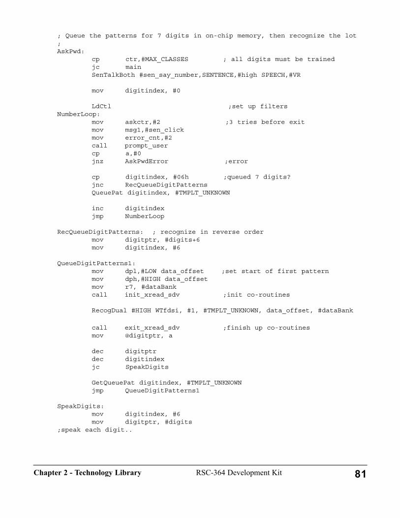
; Queue the patterns for 7 digits in on-chip memory, then recognize the lot;AskPwd:
cp ctr,#MAX_CLASSES ; all digits must be trainedjc mainSenTalkBoth #sen_say_number,SENTENCE,#high SPEECH,#VR
mov digitindex, #0
LdCtl ;set up filtersNumberLoop:
mov askctr,#2 ;3 tries before exitmov msg1,#sen_clickmov error_cnt,#2call prompt_usercp a,#0jnz AskPwdError ;error
cp digitindex, #06h ;queued 7 digits?jnc RecQueueDigitPatternsQueuePat digitindex, #TMPLT_UNKNOWN
inc digitindexjmp NumberLoop
RecQueueDigitPatterns: ; recognize in reverse ordermov digitptr, #digits+6mov digitindex, #6
QueueDigitPatterns1:mov dpl,#LOW data_offset ;set start of first patternmov dph,#HIGH data_offsetmov r7, #dataBankcall init_xread_sdv ;init co-routines
RecogDual #HIGH WTfdsi, #1, #TMPLT_UNKNOWN, data_offset, #dataBank
call exit_xread_sdv ;finish up co-routinesmov @digitptr, a
dec digitptrdec digitindexjc SpeakDigits
GetQueuePat digitindex, #TMPLT_UNKNOWNjmp QueueDigitPatterns1
SpeakDigits:mov digitindex, #6mov digitptr, #digits
;speak each digit..
81RSC-364 Development KitChapter 2 - Technology Library

10. Using Voice Record and PlaybackThe Voice Record and Playback software is available in a group of object code files for linking into aROM image. This technology requires external memory such as SRAM or Flash to hold the compressedvoice data. The Playback software can drive either or both of the RSC-364's two speech outputs, theDAC (analog waveform) and the Pulse Width Modulator (PWM). This section describes the procedureused to access Voice Record and Playback.
InitializationInitialization includes setting up the hardware and the interrupt vectors. This should be implemented bylinking-in a local copy of the module \LIB\STARTUP\STARTUP. The STARTUP module sets theprocessor speed to oscillator1 1 with 1 Wait State and initializes interrupt vectors. As a default,STARTUP sets the timer interrupt for speech synthesis only-to use voice record and playback, set theassembler variable RECPLAY to 1 at the beginning of the module (see System Configuration and I/Omapping). Sensory recommends making a local copy of STARTUP.A before editing.
In addition, certain I/O configuration must be defined. The module \LIB\STARTUP\CONFIG accom-plishes this task for the standard Development Kit hardware, and can be modified for other designs. SeeSystem Configuration and I/O Mapping for more information.
STARTUP jumps to the label INITIALIZE, which should be at the start of the application program andneeds to be PUBLIC'd for linker references. A recorder-specific version of STARTUP.A appears in the\SAMPLES\RECORDER directory.
IncludesThe voice record and playback (RP) routines should be called using macros that are defined in\LIB\MACROS\RP.INC. This file also defines various constants used by the Record and Play code. Themacros use a few memory locations that are defined in \LIB\MEMORY\MEMORY.INC. These filesmust be LIBINCL'd in the application program. See Using the RSC-364 Memory Map for detailed infor-mation.
RP uses external read/write memory, so you will need to include the definitions of the memory handlerregisters in \LIB\MEMORY\XRAM.INC. This would normally also be included in a separate devicedriver module that you must supply for the external memory device. See Using Memory Co-Routines forExternal Memory Access.
If your application uses other technology code (recognition, synthesis, etc.), include the appropriate .INCfile(s) as described in the corresponding Using... section.
LinkingLink the application code with the local version of the initialization module STARTUP, the math module\LIB364\UTIL\INTMATH, and the voice record and playback modules REC, POST, PLAY, and RP_Hin \LIB\RP. The rp_h file contains the default jumpout handler, which may be used to stop recordingand/or playback. The record jumpout is called approximately 700 times per second. Voice Record andPlayback uses resources from other technologies, so you must also link \LIB\TALK\TALKTBL.
82 RSC-364 Development Kit Chapter 2 - Technology Library
The Voice Recording technology for the RSC-364 uses the thresholding algorithm in pattern generation.If thresholding is to be enabled, link all of the pattern generation modules BLOCK, NORMAL,NULOGFNS, PATGEN, DIGAGC, STREAM, and PATGEN_H (our your replacement handler of thepatgen interrupt function). The pattern generation modules all reside in the \LIB364\PATGEN directory.These modules must also be linked if the Simultaneous Pattern Generation and Voice Recording featureis used (see below). Alternatively, if voice thresholding is to be disabled, and if your application doesnot include any form of recognition, none of these files have to be linked.
To use 3-bit and/or 2-bit compression, link CMP, 3BIT2BIT, RP3BIT and RP2BIT from the \LIB\RPdirectory, as appropriate (see compression below). Record and playback uses external read/write memo-ry, so you will also need to link in your external memory handler(s), and the configuration moduleCONFIG.O (which defines buffers for memory management-see System Configuration and I/OMapping).
Link in the memory handler for your specific external memory device. For example, the SRAM driver is\LIB\MEMORY\SRAM\RP\SRAM_RP. A different memory device requires a different driver. Toaccommodate long or multiple messages, Record and Play memory handlers should normally allowmore than 16 bits of address. The technology code supports up to 24 bits of recording data address.
Link in any required technology code modules as described in the appropriate "Using..." section.
ThresholdingThe recording code can dynamically check the signal level against a threshold. When the signal ampli-tude is small enough to correspond to a silence period the stored data encodes the duration of silencerather than the actual data itself. This technique improves the effective compression ratio.
RecordRP uses the threshold algorithm from pattern generation. The developer may choose to makevoice recordings with or without thresholding. When thresholding is used, it can be applied to allsilences, or alternatively it can be used only on the initial silence before speech begins. The sample,RECORDER, illustrates all three methods.
To make a voice recording with thresholding, first make the normal pattern generation macro calls withthe pattern generation "run_how" macro parameter set to #RP_THRESH. This starts the pattern genera-tion threshold operation running and returns. The RECORDRP macro is then invoked with its thresholdparameter set to the desired thresholding algorithm. See the explanations and sample code below.
To make a voice recording without thresholding, simply invoke RECORDRP with the threshold parame-ter set to RP_NO_THRESh.
Voice Recordings may also be made simultaneously with pattern generation. Certain restrictions apply asdescribed in the following section.
Simultaneous Pattern Generation and Voice RecordingVoice recording in the RSC-364 can run simultaneously (multi-tasked) with Pattern Generation. In thisway a single utterance can produce both a pattern for recognition (or template averaging) and a voicerecording. A voice dialing application, for example, could use this feature to record a "voice tag" to be
83RSC-364 Development KitChapter 2 - Technology Library
saved along with the template. Later, when an utterance is recognized with that template, the voice tagcould be replayed as confirmation that the correct name was recognized ("Dialing John Smith").
Using Simultaneous Pattern Generation and Voice Recording is straightforward. Set up the memory han-dler for Voice Recording as described elsewhere in this section. Initialize pattern generation as describedunder Using Pattern Generation, then invoke the PATGEN (or PATGENW) macro with the run_howparameter set to #BACKGROUND. This step starts patgen, but it pauses, waiting until RecordRP is alsorunning. Finally invoke RecordRP to begin the simultaneous patgen and recording. The threshold param-eter for RecordRP can be set to any desired value. The sample programs \SAMPL364\SI6 and\SAMPL364\SPKRDEP can each be configured to illustrate simultaneous pattern generation and voicerecording.
The duration of a Simultaneous Voice Recording is determined by the pattern generation algorithm.Once Patgen detects that the utterance is complete, the voice recording stops. The POST macro (seebelow) can be used to clean up the recording before saving it.
NOTE: when recording simultaneously, the recording is stopped when pattern generation terminates orwhen the allocated recording memory is exhausted. In the latter case pattern generation continues untilthe utterance is finished (up to 3 seconds). The pattern will be correct, but the recording will containonly the first part of the utterance.
CompressionThe RSC-364 provides three levels of voice compression. The default 4-bit compression produces amaximum data rate of 4067 bytes per second. 3-bit compression lowers the rate to 3389 bytes per sec-ond, and 2-bit gives the best rate at a maximum of 2711 bytes per second. These rates may be substan-tially lower if silence compression (thresholding) is invoked and there are many silences in the recordedspeech (see below).
During real-time recording the RP module saves voice data in 4-bit samples. Two samples are packedinto one byte and a JMP is made to an external memory handler for storage. The external handler isresponsible for managing pointers, counters, and other variables related to external memory. See UsingCo-Routines for External Memory Access for details on external memory management. Note that somememory devices may require a memory buffer during recording. Up to 128 bytes of buffer space can bemade available. See the \LIB\MEMORY\SPFLASH library for an example (using the 29EE020 flash).
After the real-time processing is completed the stored data can be selectively "post-processed", thencompressed to either 3-bits or 2-bits using macros in this package. Compression to fewer bits reducesboth memory and quality, so compression can be managed intelligently by the application to maintainhighest quality. Post processing normalizes the gain and -- if thresholding is enabled -- removes clicksand strips any leading silence.
The developer can select whether 3-bit and/or 2-bit code is included in the application. Omitting thiscode can save a substantial amount of code space if 3-bit or 2-bit compression is not needed. Edit (alocal copy of) the file 3BIT2BIT.A, and set or clear the appropriate compiler flags THREEBIT andTWOBIT (this module creates dummy stubs for modules that will be omitted from the link). Re-assem-ble 3BIT2BIT, and include it in the link. If either TWOBIT or THREEBIT is true, you must also linkCMP and the appropriate module(s) RP3BIT and/or RP2BIT. The example below shows how to setup
84 RSC-364 Development Kit Chapter 2 - Technology Library
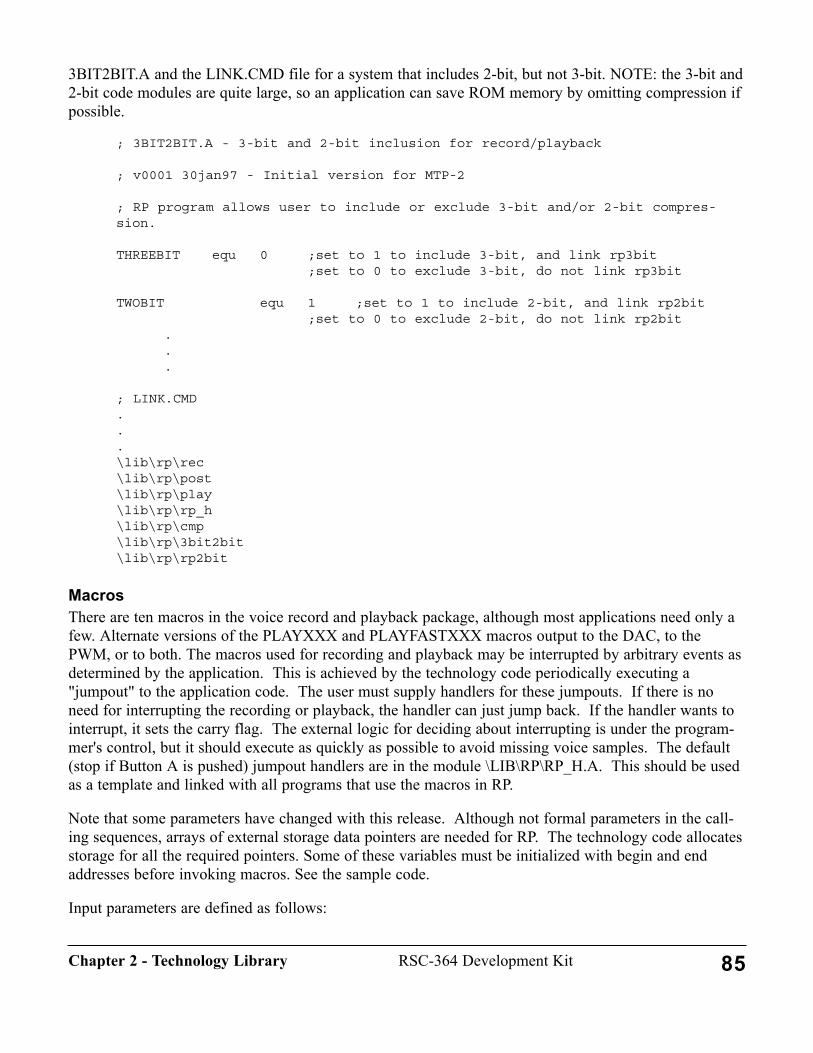
3BIT2BIT.A and the LINK.CMD file for a system that includes 2-bit, but not 3-bit. NOTE: the 3-bit and2-bit code modules are quite large, so an application can save ROM memory by omitting compression ifpossible.
; 3BIT2BIT.A - 3-bit and 2-bit inclusion for record/playback
; v0001 30jan97 - Initial version for MTP-2
; RP program allows user to include or exclude 3-bit and/or 2-bit compres-sion.
THREEBIT equ 0 ;set to 1 to include 3-bit, and link rp3bit;set to 0 to exclude 3-bit, do not link rp3bit
TWOBIT equ 1 ;set to 1 to include 2-bit, and link rp2bit;set to 0 to exclude 2-bit, do not link rp2bit
.
.
.
; LINK.CMD...\lib\rp\rec\lib\rp\post\lib\rp\play\lib\rp\rp_h\lib\rp\cmp\lib\rp\3bit2bit\lib\rp\rp2bit
MacrosThere are ten macros in the voice record and playback package, although most applications need only afew. Alternate versions of the PLAYXXX and PLAYFASTXXX macros output to the DAC, to thePWM, or to both. The macros used for recording and playback may be interrupted by arbitrary events asdetermined by the application. This is achieved by the technology code periodically executing a"jumpout" to the application code. The user must supply handlers for these jumpouts. If there is noneed for interrupting the recording or playback, the handler can just jump back. If the handler wants tointerrupt, it sets the carry flag. The external logic for deciding about interrupting is under the program-mer's control, but it should execute as quickly as possible to avoid missing voice samples. The default(stop if Button A is pushed) jumpout handlers are in the module \LIB\RP\RP_H.A. This should be usedas a template and linked with all programs that use the macros in RP.
Note that some parameters have changed with this release. Although not formal parameters in the call-ing sequences, arrays of external storage data pointers are needed for RP. The technology code allocatesstorage for all the required pointers. Some of these variables must be initialized with begin and endaddresses before invoking macros. See the sample code.
Input parameters are defined as follows:
85RSC-364 Development KitChapter 2 - Technology Library
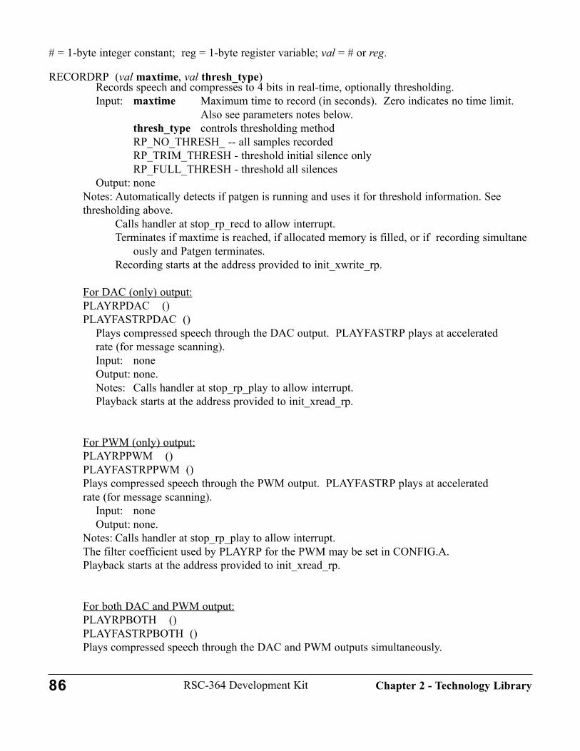
# = 1-byte integer constant; reg = 1-byte register variable; val = # or reg.
RECORDRP (val maxtime, val thresh_type)Records speech and compresses to 4 bits in real-time, optionally thresholding.Input: maxtime Maximum time to record (in seconds). Zero indicates no time limit.
Also see parameters notes below.thresh_type controls thresholding methodRP_NO_THRESH_ -- all samples recordedRP_TRIM_THRESH - threshold initial silence onlyRP_FULL_THRESH - threshold all silences
Output: noneNotes: Automatically detects if patgen is running and uses it for threshold information. Seethresholding above.
Calls handler at stop_rp_recd to allow interrupt.Terminates if maxtime is reached, if allocated memory is filled, or if recording simultane
ously and Patgen terminates.Recording starts at the address provided to init_xwrite_rp.
For DAC (only) output:PLAYRPDAC ()PLAYFASTRPDAC ()
Plays compressed speech through the DAC output. PLAYFASTRP plays at accelerated rate (for message scanning).Input: noneOutput: none.Notes: Calls handler at stop_rp_play to allow interrupt.Playback starts at the address provided to init_xread_rp.
For PWM (only) output:PLAYRPPWM ()PLAYFASTRPPWM ()Plays compressed speech through the PWM output. PLAYFASTRP plays at accelerated rate (for message scanning).
Input: noneOutput: none.
Notes: Calls handler at stop_rp_play to allow interrupt.The filter coefficient used by PLAYRP for the PWM may be set in CONFIG.A.Playback starts at the address provided to init_xread_rp.
For both DAC and PWM output:PLAYRPBOTH ()PLAYFASTRPBOTH ()Plays compressed speech through the DAC and PWM outputs simultaneously.
86 RSC-364 Development Kit Chapter 2 - Technology Library
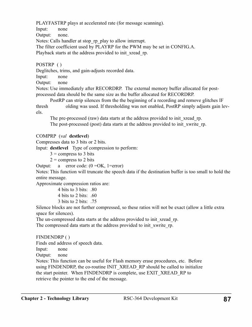
PLAYFASTRP plays at accelerated rate (for message scanning).Input: noneOutput: none.Notes: Calls handler at stop_rp_play to allow interrupt.The filter coefficient used by PLAYRP for the PWM may be set in CONFIG.A.Playback starts at the address provided to init_xread_rp.
POSTRP ( )Deglitches, trims, and gain-adjusts recorded data.Input: noneOutput: noneNotes: Use immediately after RECORDRP. The external memory buffer allocated for post-processed data should be the same size as the buffer allocated for RECORDRP.
PostRP can strip silences from the the beginning of a recording and remove glitches IFthresh olding was used. If thresholding was not enabled, PostRP simply adjusts gain lev-els.
The pre-processed (raw) data starts at the address provided to init_xread_rp.The post-processed (post) data starts at the address provided to init_xwrite_rp.
COMPRP (val destlevel)Compresses data to 3 bits or 2 bits.Input: destlevel Type of compression to perform:
3 = compress to 3 bits2 = compress to 2 bits
Output: a error code: (0 =OK, 1=error)Notes: This function will truncate the speech data if the destination buffer is too small to hold theentire message.Approximate compression ratios are:
4 bits to 3 bits: .804 bits to 2 bits: .603 bits to 2 bits: .75
Silence blocks are not further compressed, so these ratios will not be exact (allow a little extraspace for silences).The un-compressed data starts at the address provided to init_xread_rp.The compressed data starts at the address provided to init_xwrite_rp.
FINDENDRP ( )Finds end address of speech data.Input: noneOutput: noneNotes: This function can be useful for Flash memory erase procedures, etc. Before using FINDENDRP, the co-routine INIT_XREAD_RP should be called to initialize the start pointer. When FINDENDRP is complete, use EXIT_XREAD_RP to retrieve the pointer to the end of the message.
87RSC-364 Development KitChapter 2 - Technology Library

ParametersThe RecordRP maxtime parameter can be optionally be specified in units of half-seconds rather thanseconds. This gives better resolution in storage-tight applications. Edit a local copy of the RecordRPmacro (found in \LIB\MACROS\RP.INC) to set HALF_SECONDS to 1 and include this file.
The RecordRP thresh_type parameter should be set to RP_NO_THRESH if patgen is not running.When used with patgen, any valid value may be used. The PostRP function will remove any initialsilence if RP_TRIM_THRESH or RP_FULL_THRESH is selected. Internal clicks and pops will beremoved if RP_FULL_THRESH is selected.
Sample CodeThe following is a short program segment that uses voice record and playback in a single message appli-cation. See \SAMPL364\RECORDER for the full sample program. This sample uses SRAM for storingthe voice message, but non-volatile memories may also be used. (The program would have to be modi-fied.) The directory folder \LIB\MEMORY\FLASH\ contains other folders with sample code using RPwith specific Flash memories.
For clarity the sample code illustrates calling post-processing immediately after the real-time recordingis finished. In a real application this processing (and any compression) would probably be deferred untilidle time was available. This would allow smooth program flow without a processing delay after thereal-time recording. If the message is needed for replay before it can be post-processed, it can simply bereplayed as 4-bits from the original recording buffer. Careful design of memory management, bufferallocation, and program flow should allow applications to avoid any processing delays that would beobjectionable to the user.
The sample illustrates using an assembly-time constant, USE_THRESH, to control whether thresholdingis performed. This control could also be a run-time decision. Simultaneous pattern generation would beinvoked with the same flow, but the Patgen parameter would be #BACKGROUND instead of#RP_THRESH. See the SAMPL364\SI6 sample program for an example.
play_mode:...mov a,rp_start+0mov b,rp_start+1mov r0,rp_start+2call init_xread_rp ; init ext memory read
PlayRPBoth ; output to DAC and PWM
call exit_xread_rp ; finish up ext memory...
record_mode:USE_THRESH equ 1 ;set to 0 for no thresholding
.
88 RSC-364 Development Kit Chapter 2 - Technology Library

.
.mov a,#RECRD_ST_0mov b,#RECRD_ST_1mov r0,#RECRD_ST_2mov dpl,#RECRD_END_0mov dph,#RECRD_END_1mov r7,#RECRD_END_2call init_xwrite_rp ;init ext memory write: start and end
addresses
IF USE_THRESHPatGen #RP_THRESH ; run threshold part of patgen
ENDIF RecordRP #0, #RP_NO_THRESH ;record speech data, no time limit, no thresh-olding
call exit_xwrite_rp ;finish up ext memorymov rp_start+0,#RECRD_ST_0mov rp_start+1,#RECRD_ST_1mov rp_start+2,#RECRD_ST_2
mov a,rp_start+0mov b,rp_start+1mov r0,rp_start+2call init_xread_rp ;init external memory read
mov a,#B4BIT_ST_0mov b,#B4BIT_ST_1mov r0,#B4BIT_ST_2mov dpl,#B4BIT_END_0mov dph,#B4BIT_END_1mov r7,#B4BIT_END_2call init_xwrite_rp ;init external memory write
PostRP ;post-process data
call exit_xread_rp ;finish up external memorycall exit_xwrite_rp ;finish up external memorymov rp_start+0,#B4BIT_ST_0mov rp_start+1,#B4BIT_ST_1mov rp_start+2,#B4BIT_ST_2...
compress_mode: ; illustrates 2-bit, could be 3-bit...
mov a,#B2BIT_ST_0 ; set 2-bit buffermov b,#B2BIT_ST_1mov r0,#B2BIT_ST_2
89RSC-364 Development KitChapter 2 - Technology Library
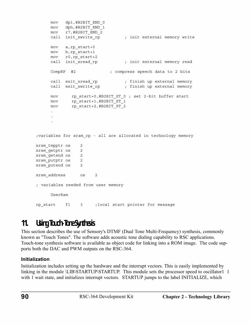
mov dpl,#B2BIT_END_0mov dph,#B2BIT_END_1mov r7,#B2BIT_END_2call init_xwrite_rp ; init external memory write
mov a,rp_start+0mov b,rp_start+1mov r0,rp_start+2call init_xread_rp ; init external memory read
CompRP #2 ; compress speech data to 2 bits
call exit_xread_rp ; finish up external memorycall exit_xwrite_rp ; finish up external memory
mov rp_start+0,#B2BIT_ST_0 ; set 2-bit buffer startmov rp_start+1,#B2BIT_ST_1mov rp_start+2,#B2BIT_ST_2...
;variables for sram_rp - all are allocated in technology memory
xram_tmpptr os 2xram_getptr os 2xram_getend os 2xram_putptr os 2xram_putend os 2
xram_address os 2
; variables needed from user memory
UserRam
rp_start fl 3 ;local start pointer for message
11. Using Touch-Tone Synthesis This section describes the use of Sensory's DTMF (Dual Tone Multi-Frequency) synthesis, commonlyknown as "Touch Tones". The software adds acoustic tone dialing capability to RSC applications.Touch-tone synthesis software is available as object code for linking into a ROM image. The code sup-ports both the DAC and PWM outputs on the RSC-364.
InitializationInitialization includes setting up the hardware and the interrupt vectors. This is easily implemented bylinking in the module \LIB\STARTUP\STARTUP. This module sets the processor speed to oscillator1 1with 1 wait state, and initializes interrupt vectors. STARTUP jumps to the label INITIALIZE, which
90 RSC-364 Development Kit Chapter 2 - Technology Library
should be at the start of the application program and needs to be PUBLIC'd for linker references.
IncludesTouch-tone synthesis should be called via a macro. LIBINCL the macros defined in\LIB\MACROS\TTONE.INC.
The TTONE macros use memory locations that are defined in \LIB\MEMORY\MEMORY.INC, so thisfile must be LIBINCL'd in the application program. See Using the RSC-364 Memory Map for detailedinformation.
LinkingLink the application with the object modules \LIB\STARTUP\STARTUP, \LIB\MEMORY\MEMORY,\LIB\STARTUP\CONFIG and the modules TTONE and TTONE_H in the \LIB\TTONE directory.
TTone HandlerThe TTONE code requires a user-supplied handler routine to know when keypresses or other eventsoccur. When an event occurs, the handler sets the carry bit. The TTONE code uses this flag in two dif-ferent ways: if the tone being synthesized is a dial tone, it will be terminated when the carry is set; if thetone being synthesized is not a dial tone, it will continue sounding until the carry is clear. The externallogic for deciding about interrupting is under the programmer's control, but it should execute as quicklyas possible to avoid missing samples. The sample callout handler shown below is from the fileTTONE_H.A, which should be used as a template and linked with the application program.
; TTONE_H.A: Touch-tone software interrupt service routine
;;;;;;;;;;;;;;;;;;;;;;;;;;;;;;;;;;;;;;;;;;;;;;;;;;;;;;;;;; INCLUDES ;;;;;;;;;;;;;;;;;;;;;;;;;;;;;;;;;;;;;;;;;;;;;;;;;;;;;;;;;;
LIBINCL "\lib\memory\memory.inc"LIBINCL "\lib\startup\io.inc" ;use project-specific i/o
;;;;;;;;;;;;;;;;;;;;;;;;;;;;;;;;;;;;;;;;;;;;;;;;;;;;;;;;;; PUBLICS ;;;;;;;;;;;;;;;;;;;;;;;;;;;;;;;;;;;;;;;;;;;;;;;;;;;;;;;;;;
PUBLIC TToneHandler
;;;;;;;;;;;;;;;;;;;;;;;;;;;;;;;;;;;;;;;;;;;;;;;;;;;;;;;;;; NOTES ;;;;;;;;;;;;;;;;;;;;;;;;;;;;;;;;;;;;;;;;;;;;;;;;;;;;;;;;;;;; The stop flag is used two different ways:;; When generating touch tones, the stop flag (carry) being set causes; the tone to continue (until the flag is no linger set).;; When generating dial tone, the stop flag (carry) being set causes; the tone to halt.
91RSC-364 Development KitChapter 2 - Technology Library

;;;;;;;;;;;;;;;;;;;;;;;;;;;;;;;;;;;;;;;;;;;;;;;;;;;;;;;;;; CONSTANTS ;;;;;;;;;;;;;;;;;;;;;;;;;;;;;;;;;;;;;;;;;;;;;;;;;;;;;;;;;;
;;;;;;;;;;;;;;;;;;;;;;;;;;;;;;;;;;;;;;;;;;;;;;;;;;;;;;;;;; START OF CODE ;;;;;;;;;;;;;;;;;;;;;;;;;;;;;;;;;;;;;;;;;;;;;;;;;;;;;;;;;;
TTone_handler: segment "CODE"
TToneHandler:
;<< insert the handler code here >>
;; Example: set the flag on button A low;
clctm BTN_A_PORT,#BTN_A_BITjnz tth_exitstc ;Carry is the stop flag
tth_exit:ret
END
MacrosIn most applications, only one macro is needed for touch-tone synthesis, but there are three versions tochoose from. Alternate versions of the macros output to the DAC, to the PWM, or to both. The macrosare defined in the file TTONE.INC, which can be found in the \lib\MACROS directory.
The TTONE macro input parameters are defined as follows: # = 1-byte integer constant; reg = 1-byteregister variable; val = either # or reg.
For DAC (only) output:TTONEDAC val tone_number, val tone_duration, val sil_duration
For PWM (only) output:TTONEPWM val tone_number, val tone_duration, val sil_duration
For both DAC and PWM:TTONEBOTH val tone_number, val tone_duration, val sil_duration
Each of these macros synthesizes the specified touch-tone, where the passed parameters are:
Input: tone_number number of the tone to be synthesized. The codes are:0 '0'1 '1'
92 RSC-364 Development Kit Chapter 2 - Technology Library
2 '2'3 '3'4 '4'5 '5'6 '6'7 '7'8 '8'9 '9'10 '*'11 '#'12 'A'13 'B'14 'C'15 'D'255 dial tone
tone_duration duration of tone in 10ms increments (minimum in North America is about 50ms).If dial tone is specified, then duration is measured in 1 second increments. A default value of100ms (10 seconds for dial tone) is defined by the constant DEF_TONE_DUR in theTTONE.INC file.
sil_duration duration of silence after tone in 10ms increments (minimum in North America isabout 50ms). A default value of 90ms is defined by the constant DEF_SIL_DUR in theTTONE.INC file.Output: none
Sample CodeThe following page shows a short complete program using touch-tone synthesis. The source files are inthe \SAMPL364\TTONES directory.
; TTONES.A - Touch-tone demo program
;;;;;;;;;;;;;;;;;;;;;;;;;;;;;;;;;;;;;;;;;;;;;;;;;;;;;;;;;; INCLUDES ;;;;;;;;;;;;;;;;;;;;;;;;;;;;;;;;;;;;;;;;;;;;;;;;;;;;;;;;;;
LIBINCL "\lib\memory\memory.inc"LIBINCL "\lib\memory\usermem.inc"LIBINCL "\lib\startup\io.inc" ;use project-specific i/o
LIBINCL "\lib\macros\ttone.inc"LIBINCL "\lib\macros\talk.inc"
;;;;;;;;;;;;;;;;;;;;;;;;;;;;;;;;;;;;;;;;;;;;;;;;;;;;;;;;;; PUBLICS ;;;;;;;;;;;;;;;;;;;;;;;;;;;;;;;;;;;;;;;;;;;;;;;;;;;;;;;;;;
93RSC-364 Development KitChapter 2 - Technology Library
PUBLIC Initialize
;;;;;;;;;;;;;;;;;;;;;;;;;;;;;;;;;;;;;;;;;;;;;;;;;;;;;;;;;; EXTERNS ;;;;;;;;;;;;;;;;;;;;;;;;;;;;;;;;;;;;;;;;;;;;;;;;;;;;;;;;;;
EXTERN VPnumbersd
;;;;;;;;;;;;;;;;;;;;;;;;;;;;;;;;;;;;;;;;;;;;;;;;;;;;;;;;;; VARIABLES ;;;;;;;;;;;;;;;;;;;;;;;;;;;;;;;;;;;;;;;;;;;;;;;;;;;;;;;;;;
UserRam ;static variables
digit_ptr fl 2digit_ctr fl 1use_areacode fl 1tmp_ptr fl 2tmp_ctr fl 1
;;;;;;;;;;;;;;;;;;;;;;;;;;;;;;;;;;;;;;;;;;;;;;;;;;;;;;;;;; CONSTANTS ;;;;;;;;;;;;;;;;;;;;;;;;;;;;;;;;;;;;;;;;;;;;;;;;;;;;;;;;;;
TONE_DUR set DEF_TONE_DUR ;(this value from include file)SIL_DUR set DEF_SIL_DUR ;(this value from include file)DT_DUR set 2 ;two seconds dial tone
VR equ 9330/64 ; VoiceRate - default sample rate (Hz/64)max=9330
; speech message constants in VPnumbersd
msg_numbers equ 0 ; 0-9, A-Fmsg_beep equ 16msg_beepbeep equ 17msg_sil30 equ 18msg_sil60 equ 19msg_sil120 equ 20msg_sil250 equ 21msg_sil500 equ 22msg_sil1000 equ 23msg_sil2000 equ 24msg_sil4000 equ 25
;;;;;;;;;;;;;;;;;;;;;;;;;;;;;;;;;;;;;;;;;;;;;;;;;;;;;;;;;; Copyright notice ;;;;;;;;;;;;;;;;;;;;;;;;;;;;;;;;;;;;;;;;;;;;;;;;;;;;;;;;;;
Copyright: segment "CODE"db " Copyright (c) 1996,97,98,99 "db " Sensory, Inc.,"
94 RSC-364 Development Kit Chapter 2 - Technology Library

db " All Rights Reserved "
;;;;;;;;;;;;;;;;;;;;;;;;;;;;;;;;;;;;;;;;;;;;;;;;;;;;;;;;;; START OF CODE ;;;;;;;;;;;;;;;;;;;;;;;;;;;;;;;;;;;;;;;;;;;;;;;;;;;;;;;;;;
TTONE_TEST: segment "CODE"
initialize:CallTalkBoth #msg_beep,#high VPnumbersd,#VR
main:tm BTN_A_PORT,#BTN_A_BIT ;button A: localjz localtm BTN_B_PORT,#BTN_B_BIT ;button B: long distancejz long_distancejmp main
long_distance:mov use_areacode,#1jmp say_number
local:mov use_areacode,#0
say_number:mov digit_ptr+0,#LOW PhoneNumbers ;point to phone numbermov digit_ptr+1,#HIGH PhoneNumbersmov digit_ctr,#11 ;dial 11 digitscp use_areacode,#0 ;if local calljnz say_number1add digit_ptr+0,#4 ; skip 1+area codeadc digit_ptr+1,#0mov digit_ctr,#7 ; dial 7 digits
say_number1:mov tmp_ptr+0,digit_ptr+0mov tmp_ptr+1,digit_ptr+1mov tmp_ctr,digit_ctr
say_number2: ;speak phone number withcp tmp_ctr,#4 ;pause at selected pointsjz pausecp tmp_ctr,#7jz pausecp tmp_ctr,#10jz pausejmp say_number3
pause:CallTalkBoth #msg_sil250,#high VPnumbersd,#VR
say_number3:movc a,@tmp_ptrCallTalkBoth a,#high VPnumbersd,#VRinc tmp_ptr+0adc tmp_ptr+1,#0dec tmp_ctrjnz say_number2
dial_number:tm BTN_A_PORT,#BTN_A_BIT ;wait for button press
95RSC-364 Development KitChapter 2 - Technology Library

jz dial_tonetm BTN_B_PORT,#BTN_B_BITjz dial_tonejmp dial_number
dial_tone:tm BTN_A_PORT,#BTN_A_BIT ;wait for button releasejz dial_tonetm BTN_B_PORT,#BTN_B_BITjz dial_toneTToneBoth #255,#DT_DUR,#SIL_DUR ;dial tone
dial_number1:movc a,@digit_ptrTToneBoth a,#TONE_DUR,#SIL_DUR ;dial digit sequenceinc digit_ptr+0adc digit_ptr+1,#0dec digit_ctrjnz dial_number1
CallTalkBoth #msg_sil1000,#high VPnumbersd,#VRjmp Initialize
;--------------------------------------------------------
PhoneNumbers:db 1, 4, 0, 8, 7, 4, 4, 9, 0, 0, 0 ; Sensory's Main Number
;--------------------------------------------------------
END
SpecificationsThe tables below show the tolerance and levels for the DTMF output.
Table 1 - Frequency tolerance of the output tones for DTMF signaling - f xtal = 14.318180 MHz
ROW/COLUMN STANDARD FREQUENCY (Hz)
TONE OUTPUT FREQUENCY (Hz)
FREQUENCY DEVIATION (%)
ROW 1 697 696.99 .002% ROW 2 770 769.96 .005% ROW 3 852 851.89 .013% ROW 3 941 940.93 .007% COL 1 1209 1208.92 .007% COL 2 1336 1335.94 .004% COL 3 1477 1476.90 .007% COL 4 1633 1632.94 .003%
96 RSC-364 Development Kit Chapter 2 - Technology Library
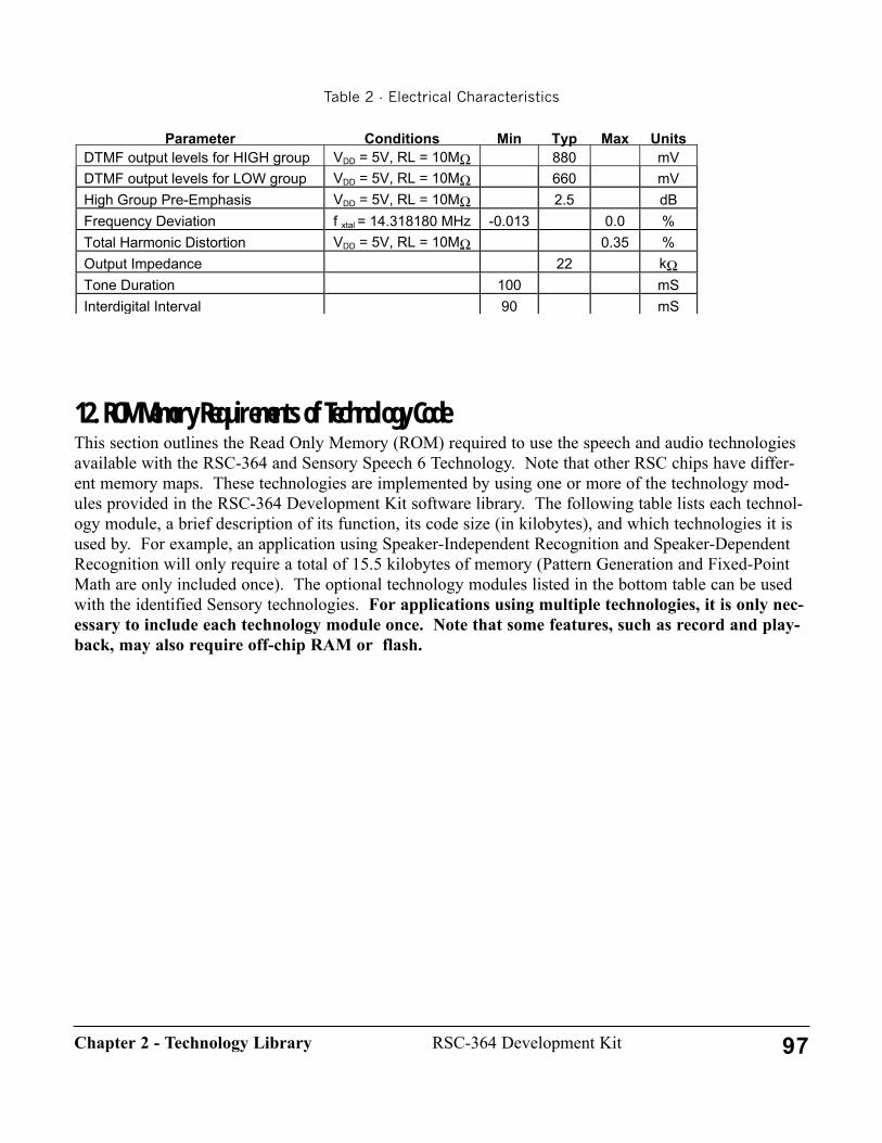
Table 2 - Electrical Characteristics
12. ROM Memory Requirements of Technology CodeThis section outlines the Read Only Memory (ROM) required to use the speech and audio technologiesavailable with the RSC-364 and Sensory Speech 6 Technology. Note that other RSC chips have differ-ent memory maps. These technologies are implemented by using one or more of the technology mod-ules provided in the RSC-364 Development Kit software library. The following table lists each technol-ogy module, a brief description of its function, its code size (in kilobytes), and which technologies it isused by. For example, an application using Speaker-Independent Recognition and Speaker-DependentRecognition will only require a total of 15.5 kilobytes of memory (Pattern Generation and Fixed-PointMath are only included once). The optional technology modules listed in the bottom table can be usedwith the identified Sensory technologies. For applications using multiple technologies, it is only nec-essary to include each technology module once. Note that some features, such as record and play-back, may also require off-chip RAM or flash.
Parameter Conditions Min Typ Max UnitsDTMF output levels for HIGH group VDD = 5V, RL = 10MΩ 880 mVDTMF output levels for LOW group VDD = 5V, RL = 10MΩ 660 mVHigh Group Pre-Emphasis VDD = 5V, RL = 10MΩ 2.5 dBFrequency Deviation f xtal = 14.318180 MHz -0.013 0.0 %Total Harmonic Distortion VDD = 5V, RL = 10MΩ 0.35 %Output Impedance 22 kΩTone Duration 100 mSInterdigital Interval 90 mS
97RSC-364 Development KitChapter 2 - Technology Library
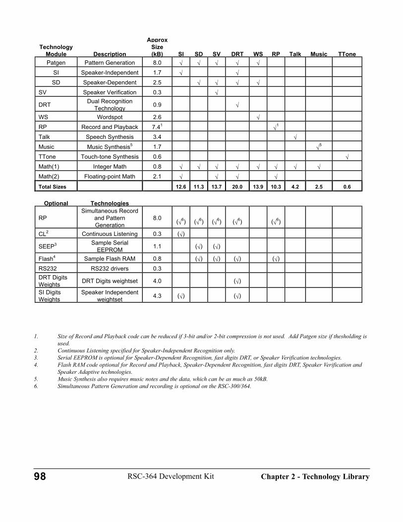
1. Size of Record and Playback code can be reduced if 3-bit and/or 2-bit compression is not used. Add Patgen size if thesholding is used.
2. Continuous Listening specified for Speaker-Independent Recognition only.3. Serial EEPROM is optional for Speaker-Dependent Recognition, fast digits DRT, or Speaker Verification technologies.4. Flash RAM code optional for Record and Playback, Speaker-Dependent Recognition, fast digits DRT, Speaker Verification and
Speaker Adaptive technologies.5. Music Synthesis also requires music notes and the data, which can be as much as 50kB.6. Simultaneous Pattern Generation and recording is optional on the RSC-300/364.
TechnologyModule Description
ApproxSize(kB) SI SD SV DRT WS RP Talk Music TTone
Patgen Pattern Generation 8.0 √ √ √ √ √SI Speaker-Independent 1.7 √ √SD Speaker-Dependent 2.5 √ √ √ √
SV Speaker Verification 0.3 √
DRT Dual RecognitionTechnology 0.9 √
WS Wordspot 2.6 √RP Record and Playback 7.41 √1
Talk Speech Synthesis 3.4 √Music Music Synthesis5 1.7 √5
TTone Touch-tone Synthesis 0.6 √Math(1) Integer Math 0.8 √ √ √ √ √ √ √ √Math(2) Floating-point Math 2.1 √ √ √ √Total Sizes 12.6 11.3 13.7 20.0 13.9 10.3 4.2 2.5 0.6
Optional Technologies
RPSimultaneous Record
and PatternGeneration
8.0 (√6) (√6) (√6) (√6) (√6)
CL2 Continuous Listening 0.3 (√)
SEEP3 Sample SerialEEPROM 1.1 (√) (√)
Flash4 Sample Flash RAM 0.8 (√) (√) (√) (√)RS232 RS232 drivers 0.3DRT DigitsWeights DRT Digits weightset 4.0 (√)
SI DigitsWeights
Speaker Independentweightset 4.3 (√) (√)
98 RSC-364 Development Kit Chapter 2 - Technology Library

99RSC-364 Development KitChapter 2 - Technology Library
100
CHAPTER 3 - SOFTWARE DEVELOPMENTThis chapter provides the developer with a variety of information to facilitate softwaredevelopment. This information is primarily reference material, not tutorial; it containsconsiderable detail. Be sure to read the Overview Chapter, especially Getting Started andthe sections dealing with hardware configuration sections before digging into this chap-ter.
The chapter includes an explanation of important considerations for inserting silencedurations with speech synthesis. There is also information about Speaker Independentrecognition accuracy and noise robustness. Another section discusses software I/O map-ping and other software configuration.
This chapter also describes the user memory map of the Register Space (on-chip RAM)for the RSC-364, which is essential information for programming the chip. This chapterdescribes a utility program, Debug Speech, which can be used to debug speech recogni-tion code. This utility uses speech synthesis to tell the programmer the value of importantparameters used in speech recognition.
Many applications require the use of external memory to store speaker dependent words,speaker verification words, and voice record and playback messages. Sensory has co-routine interfaces for SRAM, Flash memory, and serial EEPROM that are described inthis chapter. There is also a description of how to build systems that need to access mem-ory larger than the 64K bytes that can be addressed by the 16-bit address bus. Anothersection describes the Floating-Point Library Routines. This chapter also includes refer-ence tables describing stack usage by technology modules and the include/link file andco-routine requirements for each technology.
1. Software and Linguistics InteractionsIn order to create successful products, applications programmers must become knowledgeable about cer-tain linguistics issues during the development of code using speech synthesis and recognition software.This chapter gives some guidelines to assist that understanding.
SynthesisInserting Silences in the Synthesized SpeechGenerally, the linguist who generates the vocabulary will handle the silences within sentences. The pro-grammer should generally insert the silences between sentences. For example, consider the two synthe-sized sentences, "Password rejected" and "Say your password". These linguistic building blocks mightbe used separately in some places in the application, but the second might follow the first in one place inthe application flow. To create a natural pace to the speech, the programmer might put a silence of about500 milliseconds between these two sentences. Directions or questions requiring some thought or direct-ed action should be broken into two parts with a suitable silence, for example "Name not found"<silence> "Do you wish to enter this name?" Avoid adding silences that can be confusing. In this exam-ple, the user might begin speaking after the first message: "What did you say?" <silence> "repeat".Silences can be produced by calling sentences that are silence for fixed periods of time. Each vocabu-lary typically contains addresses for generating 20, 40, 80, 160, 320, 500, 1000, 2000 and 4000 millisec-onds of silence.
Inserting a Delay After the Question and Before Calling Pattern GenerationExcept for continuous listening and wordspot applications, speech recognition is typically preceded by aspeech prompt. Before recognition can begin there must be time for the room echo of the prompt todecay away. The library code provided in this release automatically monitors the echo level and detectswhen the echoes have died. If sufficient decay is not achieved within 150 milliseconds, a "spoke toosoon" error is returned. It is important that the last word of the prompt stop abruptly. If the last wordbefore recognition has a long period of low power at the end, the user may not hear this and will beginspeaking during the echo decay period, causing a "spoke too soon" error. The NO_ERROR option pro-vides an unobtrusive way of dealing with "spoke too soon" errors.
Recognition (see also Using Speaker Independent Speech Recognition)Inserting Measurements of the Silence Threshold Before Pattern GenerationThe software in previous releases required measuring the silence threshold (background noise level)before each call to the pattern generation algorithm. With the speech framing feature in this release, thatrequirement is no longer necessary.
Use of PriorsThe neural network returns speaker-independent (SI) results that include a probability distribution acrossthe various classes (answers) in the recognition set. The PRIOR macro can be used to bias the final deci-sion. If the recognition question has a preferred answer ("Are you sure?"), set the prior for that answerto twice that of other priors. This will increase the chance of the correct answer being recognized. If allanswers to the question are equally likely ("Delete?"), do not use the PRIOR macro. The PRIOR macromay also be used to remove an answer from consideration (set its probability to zero).
101RSC-364 Development KitChapter 3 - Software Development
Noise Robustness; NOTA; Yeah-Yep-Yes and No-NopeThe code in this release provides improved noise robustness and increased recognition accuracy. This ismostly achieved in the pattern generation phase, but also includes re-tuned recognition algorithms andnew SI weight sets. New weight sets are located in the \DATA\WEIGHTS\364 directory as linkableobject (.O) files.
Improved noise robustness means that recognition will perform significantly better in environments witha steady noise background (e.g. a loud fan or motor) and should also show some improvement in envi-ronments with fluctuating noise. This is particularly true of speaker dependent recognition (SD) andspeaker verification (SV).
Speaker independent weight sets include an extra recognition class, REJECT (or NOTA -- none of theabove), which helps recognition in two ways. First, if the user says an unexpected word, the recognizerwill usually return the REJECT class. For example, if the application prompts with "Continue?" and isexpecting YES/NO, but the user says, "continue", the application can deal with this result in an appropri-ate way (e.g., by saying, "Please say yes or no"). Second, if an abrupt or irregular noise occurs duringrecognition (such as a sneeze or a door slamming), the recognizer can return the REJECT class.
As in previous releases, the NOYES weight set includes the words "yeah" and "yep" (in addition to"yes") and "nope" (in addition to "no").
2. Using the RSC-364 Memory MapThis section is a description of the User Memory Map of the Register Space (on-chip RAM) for theRSC-364 Software Development Kit.
Overview of 364 Memory MapThis sub-section gives a general overview of the organization of Register Space on the RSC-364.Following sections provide details. Refer to \LIB\MEMORY\ for the memory definition files.
The RSC-364 register space is divided into ten different sections as shown in Table 1- Register Spaceusage in the RSC-364.
The table indicates that some of these sections are for the exclusive use of Sensory technology code,some of the sections can be used by both technology and application code, and some sections can bereserved exclusively for application use. Most memory is heavily overlaid (used for multiple purposes).Memory that must remain exclusively used for a single purpose is called "static" memory. The table,along with the descriptions in the following sections, should help the developer decide how to make bestuse of the memory available.
102 RSC-364 Development Kit Chapter 3 - Software Development

Table 1- Register Space usage in the RSC-364
User Memory Map DescriptionThe global registers area begins at address 00hex and consists of sixteen byte-wide registers. Sensorytechnology code uses these registers extensively, but they may be used at other times for temporary stor-age by the application. Assume that any technology call changes the values of all these locations.
These registers are commonly used to pass and return values to technology code through macros. Thedpl/dph pair may be addressed as dptr, the temp0/temp1 pair may be addressed as tempptr. The dptr, a,and b register names are aliases for special registers in the Intel 8051; note, however, that any register(pair) in the RSC-364 could perform the same operations.
The trash and temp locations are for very short-term storage only. The scall and sret macros as well asmost library functions destroy the contents of these registers.
The XRAM registers in address range 10h-20h are allocated for use as pointers for accessing externalread/write memory. Speaker Dependent/Verification, Dual Recognition, and Voice Record and Playback(RP) technologies use these registers to read and write patterns, templates, and voice recordings. Thespecific usage is different for each application and may vary for different memory parts. All memorydrivers should conform to the usage of these 17 bytes. These variables may be used for other purposeswhen technology code is not active. Applications not using RP technology normally may use locations1Bh-1Fh as statics (although some SD device drivers may make use of these locations, for example seethe serial EEPROM driver). Applications not using SD or RP technologies may use all of the XRAM
registers as statics.
Address 08h 09h 0Ah 0Bh 0Ch 0Dh 0Eh 0FhRegister dpl dph a b trash trashx temp0 temp1
Address 00h 01h 02h 03h 04h 05h 06h 07hRegister r0 r1 r2 r3 r4 r5 R6 r7
Addresses Register Description DK Use Notes00h-0Fh global registers Both temporary app use only10h-20h XRAM registers Both memory co-routine variables21h-7Fh Sensory registers Tech no app use80h-85h System Statics Tech app reference via macros86h-8Bb Debugger Reserved None future debugger use8Ch-8Fh Bank Code ROM Reserved None optional Code bankswitch90h-9Fh Stack Reserved App can use for general appA0h-BFh User Statics App no tech useC0h-DFh Banked RAM Both temporary use onlyE0h-FFh SFR registers Both IO ports, etc.
103RSC-364 Development KitChapter 3 - Software Development

The Sensory Registers in the range 021h-07Fh are reserved for the exclusive use of technology code.Any application use of this area will cause certain failure of some technologies.
The System Statics registers in address range 80h-85h are normally written only by technology code orby macros. These registers are primarily used for communication between different technologies regard-ing information such as the "owner" of the timer1 interrupt, whether to use PWM or DAC for speech,etc. Applications should normally not access these registers directly.
The six registers at 86h-8Bh are the Debugger Reserved registers. Future Development Kit releases mayprovide a debugger that would use these registers, but this release does not support such a debugger.These registers are reserved as statics for such possible future use. For this release, these registers maybe reclaimed by applications.
The four registers at 8Ch-8Fh are the Bank ROM Reserved registers. Previous releases of the RSC-164developer kit supported ROM Code Bank switching, but this release does not support ROM Code Bankswitching. These registers are reserved as statics for such possible future use. Applications for thisrelease may reclaim these registers.
An optional software stack is implemented at addresses 90h-9Fh. These Stack Reserved registers areused by applications that employ the scall (and sret) macros or use the push/pop RSC-364 instructions.The RSC-164 required extensive use of the scall and sret macros due to a shallow stack, but the RSC-364 has a deeper stack, so these macros are not required for most applications. The RSC-364 technologycode makes no use of either the scall/sret macros or the push/pop instructions, so use of the softwarestack is the choice of the developer. Information is provided here to allow using the software stack, butmost applications should reclaim this memory for expanding the User Statics area. Refer to \LIB\MEM-ORY\USERMEM.INC for more information and to enable use of the software stack.
The software stack uses an 8-bit data_stack_pointer, an 8-bit address_stack_pointer, and a combinedaddress and data stack. The address stack begins at address 92hex and grows to higher addresses (92h,93h, 94h...). The scall macro pushes two bytes of return address onto the stack and increasesadd_stack_ptr to point to the next free location. The sret macro pops two bytes of return address off thestack and decreases the addr_stack_ptr to point to the next used location. The sret macro expands into 18bytes of code, so there is typically a single instance of it at location GLOBAL_SRET. To execute ansret, the application jumps to GLOBAL_SRET. (See also The GLOBAL_SRET Code Segment below.)
Address Range 90h 91h 92h-9FhStack Usage data_stack_ptr addr_stack_ptr Data and adress stack
Address Range 10h-14h 15h-1Ah 1Bh-20hRP use low-level driver upper-level pointers upper-level pointersSD use low-level driver upper-level pointers device-specific use (20h not free)
104 RSC-364 Development Kit Chapter 3 - Software Development
The data stack begins at address 9Fhex and grows down to lower addresses (9F, 9E, 9D, 9C...). If adeveloper wants to use the software stack, but needs fewer than 14 bytes, this upper address,DATA_STACK, can be reduced by editing \LIB\MEMORY\MEMUSER. The bytes freed up may beused as static storage. The push instruction stores a byte at the address pointed to by the stack_pointerand decrements the pointer. The pop instruction increments the pointer and reads a byte at the addresspointed to by the stack_pointer. Note that address and data corruption will occur if the data and addressspaces in the stack overlap. The GLOBAL_SRET routine (see below) provides optional stack collisiondetection.
WARNINGThe software stack is not enabled by default. You must edit \LIB\MEMORY\USERMEM.INC, and youmust re-build STARTUP.A to use the stack. If you use scall or sret without doing so, your program willcrash.
Before an application can use the software stack, the pointers must be initialized.\LIB\STARTUP\STARTUP.A contains conditional code that performs this operation. After initialization,a byte at location addr is pushed on the data stack or popped from the data stack by invoking the instruc-tions shown (the instructions are similar to indirect mov and cannot take a constant argument, #byte).The instructions automatically adjust the value of data_stack_ptr. Because the stack can be located any-where in Register space, the instructions require a pointer argument.
push @data_stack_ptr, addr ; push byte at addr onto software stackpop addr, @data_stack_ptr ; pop byte into addr from software stack
The User Statics registers are addressed at locations A0h-BFh. These registers are guaranteed to beuntouched by any Sensory technology code. These 32 bytes may be used for application variables. Inaddition, virtually all RSC-364 applications will be able to obtain more storage by expanding the appli-cation variable registers downward through the Stack Reserved registers, the Bank ROM Reserved regis-ters, and the Debugger Reserved registers. This allows the application memory configurations shown.
The upper boundary of the application memory is always BFh. Under no circumstances may the lowerboundary of User Statics be set below 86h.
Most applications will define the application-static ram area by using the macro, UserRam. This macro,defined in \LIB\MEMORY\MEMUSER, automatically sizes the user statics area based on informationregarding the presence and size of the software stack. The following example illustrates a typical usage.By default, the user memory is 48 bytes. The stack can be enabled, disabled, or changed in size (seeStack Reserved discussion above).
Lower Boundary of Application Variables User Start Address Number of User BytesUser Statics A0h 32Stack Reserved (default configuration) 90h 48Bank ROM Reserved 8Ch 52Debugger Reserved 86h 58
105RSC-364 Development KitChapter 3 - Software Development

;--- sample application usage#1: User variables up to 48 bytes ; define user static ram locations (starts at 90h by default or after stack)
UserRamvariable1 fl 1 ;90hvariable2 fl 1 ;91hpointer1 fl 2 ;92hvariable3 fl 1 ;94h, etc.. . .
The application may also explicitly define specific locations within the User Statics area by use of the"fl" directive ("fixed label") relative to labels defined in \LIB\MEMORY\MEMORY.INC. The code frag-ment below illustrates this.
;--- sample application usage#2: User variables need up to 58 bytes; give up reserved areas for Debugger, Bank ROM, and software stack
custom_area fixlabel REG at dbg_stat_start ;start at 86hcustom_area fixlabel REG end at dev_area_end ;stop at BFh
;static variables
variable1 fl 1 ; 86hvariable2 fl 1 ; 87hpointer1 fl 2 ; 88-89hinPtr fl 1 ; 8AhoutPtr fl 1 ; 8BhbigBuffer fl 50 ; 8Ch-BEhbufferEnd fl 0 ; BFh (see Note below)lastByte fl 1 ; BFh. . .
NOTE: The "fl size" directive defines the label relative to the previous "fixlabel" or "fl size" directiveand steps by the size specified. No actual memory allocation is performed. In the example above, the "fl0" following the bufferEnd label assigns the value 0BFh to bufferEnd, but does not change the referencefor subsequent "fl" directives. Therefore the lastByte symbol also has the value 0BFh. No error messageis issued in this case. This side effect is a consequence of the "fl" directive, the intention of which is toavoid excessive error messages when building applications that use memory overlays. Applications forthe RSC-364 should normally build with no error messages.
The Banked RAM is used by technology code, and may also be used temporarily for buffer areas, forexample with Flash memories. Refer to Chapter 8, the RSC-364 Data Book for details on addressing andmapping of the banked register space.
The register memory (on-chip RAM) is grouped into 32 byte banks as defined in the following table:
Ram address Bank #Used for00 - 1F0 global registers20 - 3F1 technology functions40 - 5F2 technology functions60 - 7F3 technology functions
106 RSC-364 Development Kit Chapter 3 - Software Development
80 - 9F4 system statics, debugger, bank switching, user registersA0 - BF 5 user registersC0 - DF 6 bank switched ram (maps other RAM)E0 - FF 7 special function registers100 - 11F 8 technology functions120 - 13F 9 technology functions140 - 15F A technology functions160 - 17F B technology functions180 - 19F C technology functions / buffer1A0 - 1BF D technology functions / buffer1C0 - 1DF E technology functions / buffer1E0 - 1FF F technology functions / buffer
The area from 100h - 1FFh can be read/written only by using the C0h - DFh bank switched ram areaunder the control of the RAM BANK Select register (SFR address 0FCh) bits 0 - 4. Refer to the RSC-364 Data Book for a detailed description of the RAM Bank Select Register. The area from 100h - 1FFhis used extensively for technology code and should be considered as temporary storage only if thesefunctions are called. For convenience in accessing and re-defining, the assembler defines labels"bank00" - "bank1f". These symbols map to the addresses C0h - DFh.
Allocating MemoryThe memory definitions described above are mostly found in \LIB\MEMORY\MEMORY.INC. This fileshould be LIBINCLd in every application that uses scalls, technology macros, or that needs to access theglobal registers for passing arguments or for temporary scratch use. The software stack and user staticareas are defined in \LIB\MEMORY\USERMEM.INC, which must also be included in every applicationthat uses local variables. A local copy of USERMEM.INC can be edited and included to change thedefault user memory allocation and re-claim additional static storage as described above. NOTE: Toenable the software stack code, you must rebuild STARTUP.A and make sure it INCLUDEs your editedversion of USERMEM.INC. Other memory definitions may be made by include files required by vari-ous technologies
The software stack is disabled by default. It is enabled by setting the ENABLE_SW_STACK conditionalassembly flag in (usually a local copy of) \LIB\MEMORY\USERMEM.INC.
The RSC-364 assembler does not perform physical allocation of RAM memory. The labels are simplydefined and equated to the memory locations. A minor consequence of this is that the .MAP file doesnot indicate the addresses of RAM variables. This RAM address information is contained in the .SYMfile and in the .LST files.
The GLOBAL_SRET Code SegmentThe (optional) code segment GLOBAL_SRET is located in \LIB\STARTUP\STARTUP.A. This segmentsimply consists of an SRET instruction that is accessible to all code modules via a JMP instruction. Thisfeature is designed to save code space by using the instruction JMP GLOBAL_SRET anywhere that anSRET would normally be used, saving 15 bytes for each instance. This optional code is only useful inapplications using the software stack. NOTE: Most RSC-364 applications will not need to use the soft-ware stack. See System Configuration and I/O Mapping for more information. GLOBAL_SRET can
107RSC-364 Development KitChapter 3 - Software Development

also be configured to check on software stack overflow due to excess scalls (but not pushes). This codeis automatically enabled when STARTUP.A is rebuilt if the user has enabled software stack in\LIB\MEMORY\USERMEM.INC.
3. Using On-Chip Pattern StorageThe RSC-364 contains a memory block called "on-chip" or internal SRAM. This memory differs fromthe usual Register Space SRAM (which is also on-chip and internal) in the method of access and in theuse. On-chip SRAM is used intensively by the Version 6 technology software, and much of it is dedicat-ed for technology features. A portion of the internal SRAM memory is available for certain applicationuses, however. This section describes that usage.
In Release 6, Sensory is supporting three application types for on-chip memory usage: small-vocabularySD or SV, Wordspot, and fast sequential pattern queuing. Support for additional applications may beoffered in future releases.
Small-Vocabulary SD/SV"Small-vocabulary" SD/SV applications are limited to 6 templates maximum. The RSC-364 can storethese six templates in the on-chip SRAM, avoiding the need for any external memory. An ideal small-vocabulary application is SV for individual access, which requires no more than four templates. To pre-vent loss of template data, the chip MUST BE KEPT CONTINUOUSLY POWERED (it can be placedin "sleep" mode, where power consumption is negligible, but power cannot be removed). See theSPKRVER sample program, which can be configured to store templates on-chip. Also refer to Chapter2, Using Speaker Dependent Recognition, for details about using the special on-chip memory handler.On-chip template storage requires no special application coding; simply code as normal and link the spe-cial modules, LIB364\SD_SV\ONCHIP.O and \LIB364\SD_SV\AUXTMPLT.O.
An application using on-chip memory for storing templates should provide a mechanism to determine ifthe templates are valid - this could be used to tell if the chip had lost power. One possibility, illustratedin the SPKRVER sample, uses an ID string and a count of the number of templates trained. A reset or"sleep" mode would not destroy the templates or the ID string, but a power loss would.
Note, however, the ID string for onchip should NOT be stored in the on-chip template area: this wouldwaste one of the six available template slots, and also there is no supported mechanism to write individ-ual bytes to this memory. It is better to allocate a few bytes from UserRam to store the ID string andnumber of templates (password length), since the on-chip SRAM and the UserRam would both be eithervalid or invalid.
WordspotWordspot is a specialized form of SD recognition that uses parts of the on-chip template storage areaduring operation. When Wordspot is used, only the first four template storage locations are available on-chip. The Wordspot templates can be stored in some of these locations. The default configuration of thewordspot sample program uses on-chip storage for its templates.
Fast Sequential Pattern QueuingFast sequential pattern queuing is a technique used for recognizing a rapidly spoken sequence of words,for example the digits of a telephone number. The additional on-chip memory provides space for storing
108 RSC-364 Development Kit Chapter 3 - Software Development

patterns after pattern generation but before recognition. The patterns are queued during speaking andrecognized after speaking finishes. This speeds up the speaking by avoiding the recognition time. Eachnew word should be prompted by a brief "click" to indicate that pattern generation for the previous wordis done. This technique is used in the 364 sample of Fast Digits. Note, however, that the general speedupof DRT recognition in this release makes recognizing-on-the-fly competitive with queuing.
InitializationTemplate sizes are managed automatically in this release, so no initialization is needed. Up to ten Size10patterns may be queued, or six Size16 patterns. Normally SD, SV, and Wordspot patterns are Size16. SIpatterns may be Size10 or size 16.
IncludesThe pattern queuing routines should be invoked with macros defined in the include file,\LIB364\MACROS\ONCHIP.INC.
LinkingLink the low-level pattern management object code, \LIB364\SD_SV\AUXTMPLT.O with the rest ofyour code.
MacrosTwo macros provide the services to transfer pre-recognized patterns to and from the on-chip storagearea. The on-chip macro input parameters are defined as follows: # = 1-byte integer constant; reg = 1-byte register variable; val = either # or reg,
QUEUEPAT (val index, val tmpltX)Transfers the pattern from a specific area in technology RAM to on-chip memory.Input: index pattern position in sequence (0-MAX_PATTERNS-1)
tmpltX Identifier of one of three areas where the pattern can be located in the RSC-264T memory. (Normally TMPLT_UNKNOWN)
Output: carry bit 0 = ok; 1 = error
Notes: TemplateSizeXX (XX=10 or 16) must have been called previously.The parameter index is limited to:TemplateSize10 : 0 - 9TemplateSize16 : 0 - 5
The parameter tmpltX can have the following system-defined values:#TmPLT_UNKNOWN - usually the most recent patgen pattern#TMPLT_KNOWN - typically an older pattern from external memory#TMPLT_MODIFIED - typically an averaged pattern
GETQUEUEPAT (val index, val tmpltX)Transfers the pattern from on-chip memory to a specific area in technology RAM.Input: index pattern position in sequence (0-MAX_PATTERNS-1)
tmpltX Identifier of one of three areas where the pattern can be located in the RSC-264T memory. (Normally TMPLT_UNKNOWN)
Output: carry bit 0 = ok; 1 = error
109RSC-364 Development KitChapter 3 - Software Development
Notes: TemplateSizeXX (XX=10 or 16) must have been called previously.The parameter index is limited to:
TemplateSize10 : 0 - 9TemplateSize16 : 0 - 5
The parameter tmpltX can have the following system-defined values:#TmPLT_UNKNOWN - usually the most recent patgen pattern#TMPLT_KNOWN - typically an older pattern from external memory#TMPLT_MODIFIED - typically an averaged pattern
NOTE: The Pattern Queue routines CANNOT be used to save and restore previously trained templatesduring SD/SV or Wordspot recognition. The RecogSD, GetTemplate, and PutTemplate macros managethat template handling through the usual co-routine memory handlers described elsewhere in this chap-ter. The Queue routines are only for patterns to be recognized (i.e., "unknown" patterns). Since thePattern Queue routines use the same on-chip memory as the Small-vocabulary SD/SV on-chip storage,these two features may not be combined in a single application. Pattern Queuing is also not compatiblewith Wordspot.
4. System Configuration and I/O MappingThis release includes four modules that provide global information about the system configuration(amplifier, Data Space bankswitching, PWM filtering, etc.) and I/O usage. This section describes howto use these modules, and their interaction with the standard STARTUP module. For hardware configura-tion, refer to Chapter 4, Development Kit Hardware.
I/O Mapping (IO.INC)The included file \LIB\STARTUP\IO.INC is used to define the functions of various I/O bits. Some ofthe standard definitions in this module are: buttons, color LEDs, bankswitching, external memory con-trol (XML/XMH), serial EEPROM, and flash RAM. The default definitions refer to I/O usage on theRSC-364 Development Kit Motherboard.
If you need an IO configuration different from the default, Sensory recommends copying the IO.INCmodule into your working directory, and using that copy for edits (be sure that your applicationINCLUDEs that version). Please refer to the programmer note at the top of the file to determine whichmodules should be re-assembled following a change to IO.INC (these files include STARTUP and CON-FIG, memory management modules and interrupt handlers). In general, any I/O function may be re-mapped to any I/O bit.
NOTE: Although bankswitching is defined in this module, ROM bankswitching is NOT supported inthis release.
System Configuration (CONFIG.A, CONFIG.INC, CONST364.O)Certain system constants are declared in module \LIB364\CONST364.O. This file should be LIBINCLdin every application using the RSC-364.
110 RSC-364 Development Kit Chapter 3 - Software Development
System configuration is defined in the module \LIB\STARTUP\CONFIG.A. The related include file(CONFIG.INC) simply creates external references to values defined in CONFIG.A, and should not bemodified. CONFIG.A is divided into multiple sections, each of which deals with a specific item.
Global Amplifier ConfigurationThe RSC-364 contains an integrated preamplifier that always runs at maximum gain. Automatic gaincontrol (AGC) is handled through software. Applications will normally use the integrated amplifier byenabling the INTERNAL symbol (this is the default operation).
It is possible to use the RSC-364 with an external amplifier by disabling the INTERNAL symbol. Thisadds additional components and cost, so an external amplifier should not be used except in special cir-cumstances. When an external amplifier is used, it should also be fixed gain. Earlier AGC designs forexternal amplifiers are obsolete. The code dealing with AGC has been removed
NOTE: External amplifier design is a critical element in a voice recognition system. Consult withSensory before attempted such a design.
Global Bankswitching ConfigurationThe RSC-364 Developer Kit with Sensory Speech 6 Technology does not support ROM Codebankswitching. The definitions in this section are maintained for possible future use.
Debug Speech and Debug RS232Sensory provides standard speech or serial debugging output to assist developers in evaluating systemperformance. A byte in ROM memory at location DebugEnable controls the amount of debugging infor-mation output. The value of that byte, DEBUG_ENABLE, is defined in this section. Applications thatlink CONFIG.O will output debugging information accordingly. This value may also be modified direct-ly in the final ROM binary image. See the section Using Debug Speech in this chapter for more infor-mation. By default, no debug output is enabled.
Filtering for Talk and RP playbackIn most hardware systems, the PWM output is connected directly to a speaker, requiring low-pass digitalfiltering before outputting the signal. In this case, the adjustable filter coefficient should normally be setto the default value of 2. A larger value decreases the relative amount of high frequencies in the output,and a smaller value increases the relative high frequencies. Digital filtering for speech synthesis (TALK)and RP playback are controlled separately.
Digital filtering is not done on signals passed through the DAC output.
Speaker Dependent PerformanceIn this release, the sd_performance parameter is selectable at run-time, so a constant definition is notneeded. See Using Speaker Dependent Speech Recognition for more information.
Continuous Listening PerformanceIn this release, the cl_performance parameter is selectable at run-time, so a constant definition is notneeded. See Using Continuous Listening for more information.
111RSC-364 Development KitChapter 3 - Software Development

Flash BuffersSensory has defined locations for read and write buffers to be used in conjunction with external FlashRAM. Drivers for other memory devices that require buffers should use these values.
System Initialization (STARTUP.A)The module \LIB\STARTUP\STARTUP.A provides general startup initialization that can be used formost applications as-is or with minimal editing. Sensory recommends copying the STARTUP.A moduleinto your working directory, and using that copy for edits (be sure that your linker .CMD file reflects thischange).
This module sets up standard system values such as processor clock speed, wait states, wake-up regis-ters, I/O configuration, and interrupt vectors. If the software stack is being used, the module adds codefor the global_sret routine and optional stack checking, and it initializes the stack pointers. It includes aone-second-delay loop to allow the analog electronics plenty of time to power-up. Unless the applicationdoes immediate recognition, this delay loop can be reduced or eliminated.
I/O configuration is done through a series of SET pre-processor instructions. The final values are thenmoved into the I/O registers, requiring a minimal amount of actual code. The amplifier setup is provid-ed for the case of an external amplifier, but most applications will use the integrated amplifier and willnot enable this code.
Common interrupt vectors are already set up in the code, with compiler flags to enable or disable eachone. Simply set the flag for each technology that is linked into your program. NOTE: The default con-figuration of STARTUP.A requires the linker to resolve interrupt vector labels defined in pattern genera-tion and synthesis modules. If you wish to build an application using STARTUP.A without using speechor pattern generation, you must disable these flags in STARTUP.A or else you will have to link in thespeech and pattern generation files to resolve the symbols.The default version of STARTUP.A in \LIB\STARTUP has the RPM option enabled. This is required forusing the Demo Unit as a development kit, or for using the Bootload development configuration. Thisoption allocates IO pin P0.7 for use in the bootloading operation. If you do not need the bootload devel-opment configuration or want unrestricted use of P0.7, set RPM to 0.This module also contains the top-level Interrupt Service Routine (ISR) for Timer1. The timer 1 inter-rupt is used by many different technologies, so there must be some way to distinguish which routineshould receive the interrupt. This is accomplished by the system subroutine, TIC_ctl_set. The call tothis routine is normally made by the macro that invokes the technology (e.g., CallTalkBoth), making thistransparent to most developers. TIC_ctl_set sets bits in the system statics area to indicate the current userof the timer1 interrupt. The timer1 interrupt code in STARTUP.A then checks these bits to decide whereto branch. The compiler flags determine which branch tests get built into the code.
The developer can modify this code to allow independent access to timer1. See the comments in thecode and also further details in \LIB\UTIL\DELAY.INC.
The STARTUP.A module LIBINCLs \LIB\MEMORY\USERMEM.INC, which defines the presence andsize of the optional software stack. If the software stack is present, STARTUP.A will assemble code toinitialize the stack and to supply the GLOBAL_SRET module. Normally these code sections are notincluded.
112 RSC-364 Development Kit Chapter 3 - Software Development
The GLOBAL_SRET Code Segment (optional)The STARTUP module also (optionally) includes the code segment GLOBAL_SRET (located at the bot-tom of the file). This segment consists of a single SRET instruction that is accessible to all code mod-ules via a jmp instruction. This feature is designed to save code space by using the instruction JMPGLOBAL_SRET anywhere that an SRET would normally be used, saving 15 bytes for each instance.No technology code uses scall/sret, so use of the global_sret is a developer's choice. The code is addedautomatically when startup is assembled if the software stack is enabled in \LIB\MEMORY\USER-MEM.INC. Most RSC-364 applications will not enable the software stack.
As an added benefit, usage of the GLOBAL_SRET segment allows checking for some stack overflowconditions. The overflow handler routine STACK_OVERFLOW may be customized to provide appro-priate feedback (the default routine turns on all LED's and then does an infinite loop). Note that this fea-ture requires several extra processor instructions, which may cause a slight system slowdown (especiallywhen external memory handlers are used). Overflow checking is enabled by default. To disable it, sim-ply set the compiler flag OVERFLOW_ENABLE to 0. Note that the overflow check is done only whenan sret macro is invoked, so it will not detect stack overflow due to push/pop within a subroutine whosescall just fills the stack - this case will destroy the sret return address.
NOTE: The RSC-364 has native instructions push and pop which operate somewhat like the older pushand pop macros. These macros have been renamed spush and spop. The software stack code uses thenew instructions, and the old macros should be considered obsolete. They are slower, take more space,and have a different syntax.
Default I/O ConfigurationThe files described above set the I/O configuration to the default or standard state for the RSC-364Motherboard used with the I/O Module. The chart on the next page shows the standard I/O usage in var-ious configurations of these boards.
113RSC-364 Development KitChapter 3 - Software Development
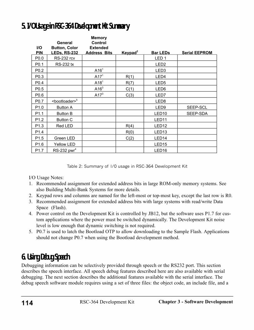
5. I/O Usage in RSC-364 Development Kit Summary
Table 2: Summary of I/0 usage in RSC-364 Development Kit
I/O Usage Notes:1. Recommended assignment for extended address bits in large ROM-only memory systems. See
also Building Multi-Bank Systems for more details.2. Keypad rows and columns are named for the left-most or top-most key, except the last row is R0.3. Recommended assignment for extended address bits with large systems with read/write Data
Space (Flash).4. Power control on the Development Kit is controlled by JB12, but the software uses P1.7 for cus-
tom applications where the power must be switched dynamically. The Development Kit noiselevel is low enough that dynamic switching is not required.
5. P0.7 is used to latch the Bootload OTP to allow downloading to the Sample Flash. Applicationsshould not change P0.7 when using the Bootload development method.
6. Using Debug SpeechDebugging information can be selectively provided through speech or the RS232 port. This sectiondescribes the speech interface. All speech debug features described here are also available with serialdebugging. The next section describes the additional features available with the serial interface. Thedebug speech software module requires using a set of three files: the object code, an include file, and a
I/OPIN
GeneralButton, ColorLEDs, RS-232
MemoryControl
ExtendedAddress Bits Keypad2 Bar LEDs Serial EEPROM
P0.0 RS-232 rcv LED 1P0.1 RS-232 tx LED2P0.2 A161 LED3P0.3 A171 R(1) LED4P0.4 A181 R(7) LED5P0.5 A163 C(1) LED6P0.6 A173 C(3) LED7P0.7 <bootloader>5 LED8P1.0 Button A LED9 SEEP-SCLP1.1 Button B LED10 SEEP-SDAP1.2 Button C LED11P1.3 Red LED R(4) LED12P1.4 R(0) LED13P1.5 Green LED C(2) LED14P1.6 Yellow LED LED15P1.7 RS-232 pwr4 LED16
114 RSC-364 Development Kit Chapter 3 - Software Development

speech data object file. There are two sets of routines in this module. The first set consists of routinesthat speak the decimal or hexadecimal value of a given nibble, byte, or word. The second set of routinesprovides Sensory's standard feedback for speech recognition.
InitializationThe debug speech software uses the Speech Synthesis code, so initialization should be done as indicatedfor that code.
IncludesThe debug speech routines are invoked with CALL. For ease of use, macros are provided for the rou-tines that give Sensory standard feedback for speech recognition. These macros, as well as external def-initions for all debug speech routines, are in the LIBINCL file \LIB364\MACROS\DEBUG_S.INC.Include this file in any modules where you want to use debug speech. Remember that these routines useSpeech Synthesis, so make sure that \LIB\MEMORY\MEMORY.INC is LIBINCLuded as indicated inUsing Speech Synthesis.
LinkingLink the debug speech object code, \LIB364\DEBUG_S\DEBUG1.O with the rest of your code. Alsolink the speech data object file \DATA\SPEECH\NUMBERSD.O. The speech file should be linked intoyour Code Space ROM, or into a Data Space ROM that contains other speech data. See Using SpeechSynthesis.
FunctionsThere are six functions in the debug speech package that speak the value of the input data. There arefive additional functions that provide the Sensory standard feedback for speech recognition (these rou-tines are incorporated into the two macros described below, so the functions are not described here).NOTE: NEVER USE THESE FUNCTIONS BETWEEN PATTERN GENERATION (PATGEN, PAT-GENW, CLPATGEN, etc.) AND RECOGNITION (RECOG, RECOGSD, RECOGSV). The debugspeech functions use memory that overwrites some of the information generated during pattern genera-tion and which is used by recognition. Placing a debug speech routine between these functions maycause recognition to return unexpected results. Debug speech can be called safely if the PUTTMPLTmacro has been called first to save the template information and the GETTMPLT macro is called follow-ing the debug output. NOTE: The following DEBUGXXX are functions (called), not macros.DebugH4(A)Speaks hex value of low nibble in AInput: A Value to be spokenOutput: '0', '1', ... 'F'. No zero-padding.
DebugH8(A)Speaks hex value of byte in AInput: A Value to be spokenOutput: '00', '01', ... 'FF'. Zero-padding to two digits.
DebugH16(A)Speaks hex value of word at RAM address pointed to by A.
115RSC-364 Development KitChapter 3 - Software Development
Input: A Address of low byte of value to be spoken (word is stored in lsb, msb order)Output: '0000', '0001', ... 'FFFF'. Zero-padding to four digits. (Word is spoken in normal msb, lsborder)
DebugD8(A)Speaks decimal value of unsigned byte in AInput: A Value to be spokenOutput: '000', '001', ... '255'. Zero-padding to three digits.
DebugD16(A)Speaks decimal value of unsigned word at RAM address pointed to by A (word stored in lsb, msb order)Input: A Address of low byte of value to be spokenOutput: '00000', '00001', ... '65535'. Zero-padding to five digits.
DebugD100(A)Speaks decimal value 0 through 100 of byte in AInput: A Value to be spoken
Output: '00', '01', ... '99', or '100'. Double-beep if A > 100. Zero-padding to two digits.
MacrosFour macros provide Sensory standard speech feedback for recognition. The output is enabled by sever-al bits in the byte DEBUG_ENABLE which may be edited in the file CONFIG.A (see SystemConfiguration and I/O Mapping above). Each bit in this byte controls a specific debug output, with azero in a bit disabling the specified output, and a one enabling the output. The values that are output areas follows:
Bit 0 Class "Answer" (which word) returned from recognition in A.Level Confidence level or score returned from recognition in B.
Bit 1 SilenceLevel Noise level measured by INITSL/GETSL.MaxPower Maximum power in spoken word measured by PATGEN.
Bit 2 AGC Setting of automatic gain control during patgen (0=lowest gain, 3=highestgain).
Bit 3 Error CodeError code returned by PATGEN in A.
The 'Class' and 'Level' values will be useful to developers for debugging program flow. The Class valuereturned is the (0-based) index of the recognized word in the weight set. Except for the digit set, weightsets are always organized in alphabetic order. 'Error Code' will also be useful in debugging programflow. 'SilenceLevel,' 'MaxPower' and 'AGC' are most useful to Sensory engineers and development sup-porters. Use the DEBUG_ENABLE byte to enable/disable some or all of these functions withoutremoving them from the code. The DEBUG_ENABLE byte does not effect the DEBUGHX() andDEBUGDX() functions.
These macros give general support for all recognition technologies.
116 RSC-364 Development Kit Chapter 3 - Software Development
DBGPATGEN( )
If pattern generation is OK, stores SilenceLevel and MaxPower in safe locations during recogni-tion, otherwise, speaks values of Error Code, SilenceLevel, MaxPower, and AGC.Input: noneOutput: speech if error, else noneNotes: Must be called immediately following PATGEN. This macro does not invoke Speech
Synthesis if the pattern generation was successful. The value of DEBUG_ENABLE indicates which values to speak as indicated above.
The possible ErrorCodes returned by PATGEN and spoken by DBGPATGEN are:
1: timeout (no data)2: spoke too long (too much data)3: background level too noisy 4: spoke too softly5: spoke too loudly 6: spoke too soon 7. too choppy (too many speech segments)8. bad weights (format not correct)FF: user interrupted patgen operation
DBGRECOGSI( )Speaks values of recognition variables: Classes, Levels, SilenceLevel, MaxPower, and AGC.Input: noneOutput: speech Notes: Must be called immediately following a call to RECOG (or following PRIORS if
used). The value of the DEBUG_ENABLE byte indicates which values to speak as described above. If the Class/Level bit is set, the following data are spoken in order:
- Best Class (0 to number of words in set minus 1; double-beep if NOTA)- Confidence level (1-100)- Second best match- Confidence of second best match (*)- Third best match7- Confidence of third best match (*)
(*) If the confidence is 0, a short "double-beep" sounds. Double-beep also is used to indicateNOTA as the class. RS232 output denotes NOTA as "99".
DBGRECOGSD( )Speaks values of Speaker Dependent recognition variables: Classes, Scores, SilenceLevel,MaxPower, and AGC.Input: noneOutput: speech Notes: Must be called immediately following a call to RECOGSD. The value of the
DEBUG_ENABLE byte indicates which values to speak as described above. If the
117RSC-364 Development KitChapter 3 - Software Development

Class/Level bit is set, the following data are spoken in order:- One digit pass code- Best Class (0 to number of words in set minus 1)- Best Score (0-255), lower is better- Second best match Class- Second best score (0-255)
DBGRECOGSV( )Speaks values of Speaker Verification recognition variables: Pass/Fail, Class, Scores,SilenceLevel, MaxPower, and AGC.Input: noneOutput: speech Notes: Must be called immediately following a call to RECOGSV. The value of the
DEBUG_ENABLE byte indicates which values to speak as described above. If the Class/Level bit is set, the following data are spoken in order:
- One digit sequence pass code (0:pass, 1:fail, FF(double-beep)=undecided)- One digit utterance pass code (0:pass, 1:fail)- Best Class (0 to number of words in set minus 1)- Cumulative Score (0-255) - unlike SD, Higher is better
Sample CodeThe following is a short program segment using debug speech and Sensory standard feedback forSpeaker Independent speech recognition. A similar model is used for Speaker Dependent.
.mov a,value1 ;byte to speakcall DebugH8 ;speak byte A in hexadecimalmov a,#dpl ;address of word to speak
call DebugD16 ;speak 16-bit word at address dpl:dph in decimal...start_patgen:
PatgenW #high Wtweights, #0 ;generate the pattern for a SI spokenword
DbgPatgen ;save silence_level and max_power values. ;on error, speak error code, silence level, max power,AGC..patgen_ok:
Recog #high WTweights ;compare against weight setPrior answer, #1 ;prioritize answer (optional)DbgRecogSI ;speak classes, levels, silence level, max
power, AGC.
7. Using PC Output
118 RSC-364 Development Kit Chapter 3 - Software Development
The RSC-364 Development Kit incorporates software and hardware to allow use of familiar serial com-munications using the RS-232C standard. The Motherboard contains circuitry to provide the requiredsignal levels to external devices such as terminals or a PC, even when the Development Kit is operatedat 3 Volts. A shutdown control is provided in the software to reduce circuit noise during pattern genera-tion and voice recording.
Operation is simplified by hardware design that uses only serial transmit and serial receive signals; allother control signals are "looped back". No flow control is implemented.
Software comprises two modules, one of which contains a few basic, low-level routines to configure theRS-232 system, to receive a character, or to send a character or string. A second module provides for-matted serial output of the familiar "debug speech" functions. These functions offer Hex or Decimal out-put of nibble, byte, or word values. The formatted output package contains equivalents for all the macrosand functions described in Using Debug Speech. The DEBUG_ENABLE byte described in that sectionhas the same operation when the output is directed to RS-232. See that section for details on use of the"debug" output capabilities. The default operation of the \SAMPL264\SI6 demo is to output full debug-ging information to the RS232 port.
If you use the bootloader software to load programs, be sure to read the section on configuring the Serialport in the Overview chapter.
InitializationThe RS-232 software uses a default baud rate of 9600 bits/sec. (An exception is that the bootload pro-gram runs at 115K baud). The baud rate is determined by the constant, BAUD_COUNT, defined inCONFIG.A. Edit and re-assemble CONFIG.A to change the baud rate. The software also needs three IObits for transmit, receive, and power control. The default values for these are set in IO.INC. Changingany of these bits requires editing IO.INC and re-assembling \LIB\RS232\RS232.A. If you use the defaultconfiguration, initialize the RS-232 operations using the INIT232 macro. The software uses pollingrather than interrupts, so no other initialization is required. The 364 Development Kit and Demo Uniteach include circuitry to produce the required +5V/-10V serial interface voltages when the unit is operat-ing from 3V. This RS232 power converter is electrically noisy, and with certain PCB layouts may gener-ate noise that can affect recognition. It is recommended that the Idle232 macro be invoked before eachcall to pattern generation to prevent this potential problem. The Idle232 macro includes required timedelays. NOTE: Insert the Idle232 macro before the prompt, NOT between the prompt and the call toPatgen. Otherwise the user will likely begin talking during the RS232 shutdown time, causing a "spoketoo soon" error. After pattern generation returns, the RS232 can be re-enabled with the Init232 macro.The RS-232 should be disable during continuous listening or wordspot.
IncludesThe RS-232 routines should be called using the macros defined in \LIB\MACROS\RS232. Include thisfile in your application. These macros are described below.
LinkingLink the application code with the lower-level driver routines in \LIB\RS232\RS232.O. To use the deci-mal and hex formatted numeric output routines, link in \LIB364\DEBUG_S\DEBUG232.O. The namesof routines in this module are the same as those in the speech version, \LIB364\DEBUG_S\DEBUG1,
119RSC-364 Development KitChapter 3 - Software Development

so you may not link both of these modules in the same application.
MacrosThere are seven macros in the lower-level RS-232 package. The RS232 macro input parameters aredefined as follows:
# = 1-byte integer constant; reg = 1-byte register variable; val = either # or reg,caddr = 16-bit address in Code Space
PUTBYTE232 (val ascii)Transmits one character out of the RS232 channel.
Input: ascii ASCII-format character to transmitOutput: carry bit 0 = ok; 1 = errorNotes:
WAITBYTE232 ( )Waits until a character is received on the RS232 channel and returns it in the A register.
Input: noneOutput: a ASCII-format character receivedNotes: Waits forever if no character is received.
ANNOUNCE ( caddr message)Sends a null-terminated Code Space string to the RS232 channel.
Input: message ASCII-format character string to transmitOutput: noneNotes: Message must be terminated by a NULL character (00h). The null character is not trans-mitted.
CRLF ( )Transmits a carriage-return/line-feed sequence out of the RS232 channel.
Input: noneOutput: carry bit 0 = ok; 1 = errorNotes:
INIT232 ( )Prepares the RS-232 channel for operation.
Input: noneOutput: none
120 RSC-364 Development Kit Chapter 3 - Software Development
Notes: Powers up the RS232 circuits and sets port directions.
IDLE232 ( )Puts the RS-232 channel in idle state.
Input: noneOutput: noneNotes: Powers off the RS232 circuits. Should be done before Patgen and GETSL.
The following macro requires interrupt-driven software not supplied in this release. The code isprovided for developers who wish to develop such software for higher-performance applications.This macro should not be used with the RS232 low-level routines provided in \LIB\RS232. UseWAITBYTE232 instead.
GETBYTE232 ( )Reads a character on the RS-232 channel immediately and returns it in the A register.
Input: noneOutput: a ASCII-format character receivedNotes: Assumes the start bit has already begun when called.
Sample CodeThe following is a short program segment using RS-232 functions to implement a simple command dis-patcher using one-character commands received from a terminal. See \SAMPL364\RS232 for the fullsource code, expandable working sample menuing system, and more RS-232 examples.
; SERIAL communication RS232 sample...Initialize: ;startup comes here
Init232 ; ready rs232 for operationAnnounce Greeting ;display greetingAnnounce Help ;display menu
Loop: ; Loop to get command and dispatchWaitByte232 ;get char in Aor a, #20h ; tolower(a)cp a, #'a'jz DoCommandAcp a,#'b'jz DoCommandB
;. . . additional one-character commands as abovecp a, #'?'jz HelpCmd
cp a, #';' ; commentjz Comment
jmp Loop ;ignore unknown commands
121RSC-364 Development KitChapter 3 - Software Development
;. . . more code for command handling
;-------------------------- Messsage strings in Code Space --------------------Messages segment "CODE"NULL equ 0 ;end-of-messageGreeting
db 13, 10 ;crlf in stringdb "Hello, World"db NULL
Help; db continues for menu lisitng and other messages as required
8. Using Co-Routines for External Memory AccessMany of Sensory's technologies require access to information in external memory. Speaker Dependentrecognition, Speaker Verification recognition, Wordspot SD recognition, Dual Recognition, and VoiceRecord and Playback each may require external read/write memory to hold the template or voice data.Speaker Independent recognition and Speech Synthesis each require read-only memory to hold therecognition weights or speech data. Due to the wide range of memory products available (SRAM, FlashRAM, Serial EEPROM, etc.), the differences from one device to another, and the very fast rate at whichmemory technologies change, Sensory cannot provide individual support for every memory device.Instead, Sensory's technology library routines call customer-supplied memory handler co-routines to pro-vide external read/write (or read-only) memory access. Sensory supplies software handlers for a varietyof popular memories. These handlers may be used directly or as models for other devices.
This chapter describes the co-routine interface. Unless otherwise mentioned, memory in this chaptermeans external memory. The memory handler is the co-routine part of the application code written bythe user that handles the operations necessary to deal with the memory. The technology code providesspecific services (currently Voice Record and Playback, Speaker Verification, Speaker Dependent recog-nition, Speaker Independent recognition, Dual Recognition, and speech Synthesis), and requests thememory handler to manage the details of communicating with the memory. The memory handler and thetechnology code typically communicate on a byte-by-byte basis. The interface between the technologycode and the memory handler is the same for all memory types. The technology code is unaware of thedetails or even the type of external memory used by the application.
In concert with the general approach to software handling, the Development Kit hardware supports virtu-ally any device by use of the various sockets, prototyping area, and logic prototyping locations on theMemory Module. As part of the system design, keep in mind that interruption of the power during awrite cycle to external memory can cause loss of data.
Memory TypesEach class of memory device has specific issues to address. These issues need to be well understoodbefore a memory device is selected and the co-routines are implemented.
122 RSC-364 Development Kit Chapter 3 - Software Development

Data SpaceExternal memory devices with parallel data organization will typically interface to the RSC-364 via theaddress and data buses. Any such read/write device must be in external Data Space, but some programsmay also use external Data Space ROM for speech and recognition files. Using a parallel device in suchan application normally requires a dedicated I/O pin (e.g., ROM/RAM) and decoding to select betweenData Space access to the read/write memory and Data Space access to the ROM. Although theMotherboard does not support such a configuration directly, it can readily be wired up on the MemoryModule, as it is a common configuration. In this release of the Developer Kit, the SRAM and the Flashmemories interface with parallel data space access.
The RSC-364 maps some addresses in the last page of each Data Space bank (addresses 0xFFxxh) tointernal functions. This last page is inaccessible to external devices and must be avoided in any memoryhandler. That is, the next sequential access to external memory after 0FEFFh must be 10000h. Driverexamples in the \MEMORY\FLASH sub-directories illustrate different methods of avoiding page FF.
IMPORTANT NOTICEThe handler code to map around page FF may cause reads/writes to be directed to physical addressesdifferent from the logical addresses supplied. For most use this is not important. But the programmerwho needs to access a specific physical location (for example, to unlock write-protection for somedevice) should not use these handlers, or should comprehend the details of how they work.
SRAMThis is the easiest type of memory to work with, having a parallel interface. Co-routines can simply con-sist of a MOVX followed by a return (or jmp). There are no specific issues to address other than DataSpace decoding. In most instances the application will need to implement a pointer. The major disadvan-tage of SRAM is that data are lost when power is removed (volatility).
Flash RAM/EEPROMThis memory technology has many variations, but the main characteristic is that the storage is non-volatile. The names "Flash" and "EEPROM" are used more-or-less interchangeably. Some forms of thismemory function like an SRAM or EPROM when reading, but may have a fairly complex write proce-dure that varies from device to device. A major issue in dealing with Flash is often erasing. Flash RAMmust sometimes be explicitly erased (in whole-sometimes-large-blocks) before new data can be written.Flash is available in large sizes suitable for extended voice recordings. Interface may be parallel, so DataSpace decoding must be considered (for example, the Atmel or SST Flash).
Using Flash RAM may require a portion of the RSC-364's on-chip RAM to be used as a buffer. In thesample code, RAM banks 0Ch-0Fh are used to create a 128-byte temporary buffer. In addition, specialconsideration should be given to the Flash RAM's block size and write cycle timing. The RSC-364 canbe programmed with extended wait states for movx instructions to create a long write or read pulse thatmay be suitable for some slow Flash memories. See the description of the Oscillator1 Extended RegisterOSC1EXT (0F7h) in the RSC-364 Data Book. The Atmel page-mode Flash driver (in\LIB\MEMORY\FLASH\SPFLASH) and the SST 28SF040 driver (in \LIB\MEMORY\FLASH\SST)illustrate use of extended movx wait states.
123RSC-364 Development KitChapter 3 - Software Development

Sensory provides complete working sample code for one popular group of Flash parts that interface viathe address bus and dedicated I/O pins (which provide extended address bits). Data transfers are strobedby the -WRD and -RDD signals (MOVX instructions). For more details, see Using Page Mode Flash,below. A sample Flash driver is also supplied for the 28SF040, a 4-Mbit flash from SST.
Serial EEPROMAccess to and from these non-volatile parts is achieved via a bit-serial data bus. Two common protocolsare 2-wire (or I2C) and 3-wire. 3-wire parts are typically faster and smaller than 2-wire parts. Like aFlash RAM, data must be erased before the memory space can be overwritten, although most modernparts erase transparently.
SEEPROMs are commonly available in sizes up to 8K bytes. This size is too small to store voice record-ings, but large enough to store many speaker dependent or password templates. Because of its low costand small physical size, Serial EEPROM is a good medium for SD applications that do not require voicerecording. Speed is generally not an issue when storing templates because of the small amount of data,but it is an issue for voice recordings with serial memories. Voice Record and Playback requires a con-tinuous throughput rate of roughly 4000 bytes/second.
Sensory provides sample code for using Microchip 2-wire SEEPROMS from 24C01 through 24C64/65.These routines allow storing and retrieving templates for password or speaker dependent technologies, aswell as randomly reading and writing individual bytes. The code has also been used successfully withserial EEPROMS from Atmel and other manufacturers.
Memory Co-routines for Read-Only DevicesMemory co-routines are also used with some data stored in read-only memory. The speech synthesis andSI recognition technologies call memory handlers to provide the required data bytes. Typically these datawould be stored in EPROM or ROM, and the co-routine approach supports placement of speech dataand SI weights (independently) in either Code Space or Data Space as the developer chooses. Use ofData Space placement can ease the "ROM crunch" in larger applications and can allow rapid prototypingof speech vocabularies. A high level of speech compression is not required because there is more avail-able memory. For example, a single 64K binary can be created with executable, speech data, and weightsall in Code Space (if the code fits). Typically such a program would consist of about 32K of code and32K of speech data. If this application had a 40 word vocabulary, then speech would have to be com-pressed to 800 bytes/word. This level of compression at good quality requires many hours of linguisticwork.
Alternatively, a larger 128K program can be built with 64K of executable code and 64K of speech dataplus recognition weights (or 64K of code plus weights and 64K of speech data). The 40-word vocabu-lary now needs to be compressed only to 1600 bytes/word, and this can be done quickly and inexpen-sively. A larger program of this type can fit in a single 1Mbit ROM. A simple decoding scheme coulduse Code Space in the lower 64K and Data Space in the upper 64K, with address bit A16 controlled bythe -RDC signal. Note, however, that other use of Data Space (e.g., parallel Flash) requires additionaldevice decoding as described above.
Implementation OverviewThe function of a co-routine is to transfer one byte of data between the memory handler code and the
124 RSC-364 Development Kit Chapter 3 - Software Development

technology code. The memory handler code moves the data into or out of external memory. This can beimplemented by a simple MOVX command, a serial transfer via GPIO, or a buffering system that trans-fers data in blocks. In any case, the interface to the technology code is one byte.
The data transfer routines supplied by the memory handler are co-routines because they are not normallycalled directly by the application; rather the application makes a request for technology service, and thetechnology code calls the co-routine. The technology code may also provide additional informationwhen it calls the co-routine, or it may call additional helper co-routines. For example, during SpeakerDependent recognition, the recognition technology code makes 128 calls to the memory handler toobtain each byte of the first template. Before beginning this sequence of calls, the co-routinevalidate_template_sdv would be called with the first template number. This co-routine sets up the point-ers to access the template and initializes any counters. The sample code illustrates this.
The application must initialize the memory co-routines before calling the technology function that willuse them. Initialization involves providing a starting address. Some memory types may require addition-al specific setup or shut down procedures, for example to write out a partially-filled buffer. The appro-priate initialization routine should be implemented in the application and called once before calling thetechnology code that will read or write. The exit routine should be called after the technology code hasreturned. As shown in the samples, most memory co-routines should support the following entry points(XXX is either SDV or RP):
init_xwrite_XXX (called by application to initialize co-routine) exit_xwrite_XXX (called by application to terminate co-routine)init_xread_XXX (called by application to initialize co-routine) exit_xread_XXX (called by application to terminate co-routine)get_byte_XXX (called by technology code when it needs a byte)put_byte_XXX (called by technology code when it has a byte)
Detailed descriptions and examples of these functions for SD_SV are given below.
In some cases data storage or fetch requests may be made by the technology code via JMPs, notCALLS. This is mainly to minimize stack depth. The data to be transferred will typically be passed invariable "A". Memory addressing is the responsibility of the co-routine. The co-routine must not disturbglobal registers other than "A". All of the required pointers required for SDV and RP technologies areallocated in system memory and defined in \LIB\MEMORY\XRAM.INC. Any other required storagemust be provided by the application. Use the samples as a guide to writing drivers for other devices.
Affected CodeSensory currently has three technologies that rely upon external read/write memory: Speaker Dependentrecognition, Speaker Verification, and Voice Record and Playback. Two technologies use co-routines forread-only access: speech synthesis and SI recognition. Co-routines may be developed individually foreach of these functions to allow the greatest flexibility (e.g., a product uses Flash RAM for record andplayback, but stores passwords in a serial EEPROM). The memory requirements of speaker verificationand speaker dependent recognition are basically identical, so they may share the same co-routines.Wordspot can recognize only a single utterance at a given time, so the application can load the templatefor the trigger word directly, and the wordspot technology code does not need to reference externalmemory.
125RSC-364 Development KitChapter 3 - Software Development
Speaker Dependent/Speaker Verification (SD_SV)This technology uses external memory to store one or more templates of 128 bytes each. Memorywrites are done by a call to put_byte_sdv, while reads are accomplished with a call to get_byte_sdv.There are no critical timing issues for these routines, but the execution time of get_byte_sdv will effectthe overall response time when recognizing or verifying an unknown word. The resulting delay maybecome more noticeable when a large number of templates are in the speaker dependent recognition set.An additional co-routine, validate_template_sdv, provides the means for the application to tell the tech-nology code to skip certain templates (for example, ones that have been deleted). This can speed uprecognition and simplify memory management. Refer to The Validate_template_SDV Function, below,for details.
Read/write co-routines are typically implemented as two layers. The low-level modules provide generalpurpose access routines for writing, reading, erasing, and the like. These lower-layer routines are con-tained in \LIB\MEMORY\XXX, (where XXX is FLASH, SEEPROM, OR SRAM). The flash directoryhas sub-directories for each supported part. Higher-level modules provide the technology-specific mem-ory management for SD_SV in \LIB\MEMORY\XXX\SD_SV.
This release also includes SD/SV support for a group of Flash RAMs (see the example code in\LIB\MEMORY\FLASH\XXX\SD_SV).
A special set of memory co-routines for SD/SV provides support for 6 or fewer words stored on-chipwith no external memory in the RSC-364. These routines are in the \LIB364\SD_SV\ONCHIP.O modulerather than in the memory folder.
In order to access templates for SD/SV, the application program takes the following actions:
• Initialize xram_sdv_base to point to the base of the template set and perform any hardware ini-tialization needed to access external memory ( done by init_xread_sdv or init_xwrite_sdv,because different initialization is needed for read/write )
• Initialize xram_sdv_ptr to point to the start of the current template ( done byvalidate_template_sdv )
• Setup hardware lines, as needed, to access the current template (may be done by validate_template_sdv, once per template, or by get_byte_sdv/put_byte_sdv, once per byte)
• Call one of the following technology routines: RecogSD, RecogSV, TrainSD, TrainSV,GetTemplate, or PutTemplate. These routines in turn call get_byte_sdv, put_byte_sdv,validate_template_sdv
• Finish up memory access, e.g. writing out buffered flash page ( done by exit_xread_sdv or exit_xwrite_sdv, different actions needed for reads, writes )
The table shows the individual SD_SV memory handler routines. See overall flow below for usageexamples.
126 RSC-364 Development Kit Chapter 3 - Software Development
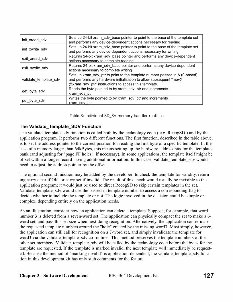
Table 3: Individual SD_SV memory handler routines
The Validate_Template_SDV FunctionThe validate_template_sdv function is called both by the technology code ( e.g. RecogSD ) and by theapplication program. It performs two different functions. The first function, described in the table above,is to set the address pointer to the correct position for reading the first byte of a specific template. In thecase of a memory larger than 64kBytes, this means setting up the hardware address bits for the templatebank (and adjusting for "page FF holes", if necessary). In some applications, the template itself might beoffset within a longer record having additional information. In this case, validate_template_sdv wouldneed to adjust the address pointer by the offset.
The optional second function may be added by the developer: to check the template for validity, return-ing carry clear if OK, or carry set if invalid. The result of this check would usually be invisible to theapplication program; it would just be used to direct RecogSD to skip certain templates in the set.Validate_template_sdv would use the passed-in template number to access a corresponding flag todecide whether to include the template or not. The logic involved in the decision could be simple orcomplex, depending entirely on the application needs.
As an illustration, consider how an application can delete a template. Suppose, for example, that wordnumber 3 is deleted from a seven-word set. The application can physically compact the set to make a 6-word set, and pass this set size when next doing recognition. Alternatively, the application can re-mapthe requested template numbers around the "hole" created by the missing word3. Most simply, however,the application can still call for recognition on a 7-word set, and simply invalidate the template forword3 via the validate_template_sdv co-routine. This method preserves the template numbers of theother set members. Validate_template_sdv will be called by the technology code before the bytes for thetemplate are requested. If the template is marked invalid, the next template will immediately be request-ed. Because the method of "marking invalid" is application-dependent, the validate_template_sdv func-tion in this development kit has only stub comments for the feature.
init_xread_sdv Sets up 24-bit xram_sdv_base pointer to point to the base of the template setand performs any device-dependent actions necessary for reading
init_xwrite_sdv Sets up 24-bit xram_sdv_base pointer to point to the base of the template setand performs any device-dependent actions necessary for writing
exit_xread_sdv Returns 24-bit xram_sdv_base pointer and performs any device-dependentactions necessary to complete reading
exit_xwrite_sdv Returns 24-bit xram_sdv_base pointer and performs any device-dependentactions necessary to complete writing
validate_template_sdvSets up xram_sdv_ptr to point to the template number passed in A (0-based)and performs any hardware initialization to allow subsequent "movX@xram_sdv_ptr" instructions to access this template.
get_byte_sdv Reads the byte pointed to by xram_sdv_ptr and incrementsxram_sdv_ptr
put_byte_sdv Writes the byte pointed to by xram_sdv_ptr and incrementsxram_sdv_ptr
127RSC-364 Development KitChapter 3 - Software Development
A simple illustration depends on the fact that the first byte of a template encodes the template size (nor-mally 010h = 16d). An application could "erase" a template (remove it from recognition consideration)by writing a "0" to the first byte of the template. Then validate_template_sdv would check the first byte:if its value were 16, the template would be marked valid; if 0, it would be marked invalid. The applica-tion could later return the template to the recognition set by restoring the 16 value.
A more complicated dialer application might maintain an array of user IDs and directory membershipsindexed by template number. Validate_template_sdv would access this array to decide about templatevalidity.
NOTE: Different devices might have different assumptions about how templates are stored, and this isOK as long as validate_template_sdv can calculate where a given template is stored ( e.g. some devicesmight have 128 byte pages, while others might have 256 byte pages ).
Voice Record and Playback (RP)This technology uses external memory to store voice data recorded through the microphone. Four-bitcompression allows a storage ratio of about one second per four Kbytes of memory, so products usingthis technology will probably use a large SRAM or Flash RAM. There are several components in theRP package, with varying needs. The playback routines only read from external memory, so timingissues should be minimal. Compression (to 3 or 2 bits) requires a lot of reading and writing, and careneeds to be taken when using a memory that must be erased (Flash RAM). Compression routines do notrun in real-time, so timing is not critical, but processing large amounts of data is time consuming, andevery cycle counts. Recording writes data to external memory in real-time and also does some post-pro-cessing. Great care should be taken in developing related co-routines - the recording code is both com-plex and time-critical, and integrating Flash RAM write cycles and block divisions can get very tricky.As a further complexity, Record must often operate concurrently in a multi-tasking fashion with patterngeneration.
Sensory has implemented sample co-routines for Voice Record and Playback for SRAM and for certain1-, 2-, and 4-Mbit Flash memories. The RP co-routine implementation contains several "housekeeping"routines for adjusting pointers and the like. Record and Play co-routines typically use the same low-levelcode as SD_SV. See the RP-specific sample codes in the \LIB\MEMORY\FLASH\XXX\RP directory.
RSC Memory RequirementsMemory co-routines may use RSC-364 Register memory available in the XRAM Registers area for anypermanent storage (for example, pointers or counters). For Voice Record and Playback, an additionalcommon buffer space has been made available in the RSC's on-chip RAM. This 128 byte buffer spaceis located in banks C through F of the banked RAM area (accessible through addresses C0h - DFh, andthe BANK register). This space is only available during portions of the RP code which need externalmemory access; it cannot be used during portions of the SD_SV technology.
Overall FlowA simple illustration of the overall co-routine flow in pseudo-code is shown for the case of storing a sin-gle speaker dependent recognition pattern.
128 RSC-364 Development Kit Chapter 3 - Software Development
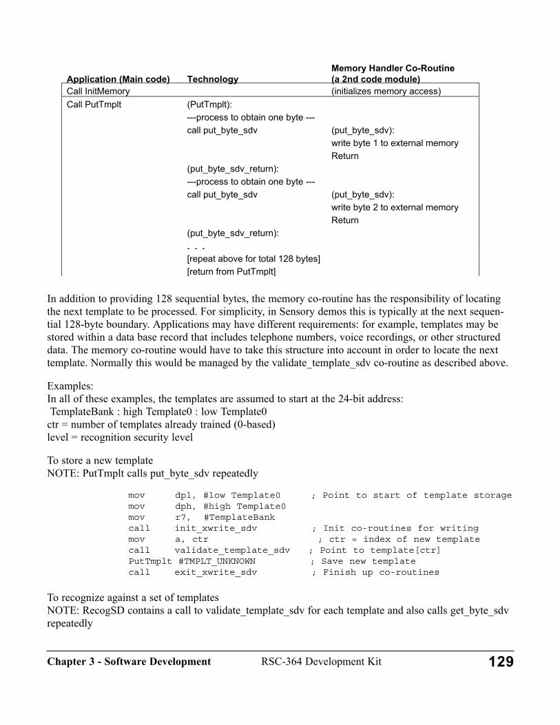
In addition to providing 128 sequential bytes, the memory co-routine has the responsibility of locatingthe next template to be processed. For simplicity, in Sensory demos this is typically at the next sequen-tial 128-byte boundary. Applications may have different requirements: for example, templates may bestored within a data base record that includes telephone numbers, voice recordings, or other structureddata. The memory co-routine would have to take this structure into account in order to locate the nexttemplate. Normally this would be managed by the validate_template_sdv co-routine as described above.
Examples: In all of these examples, the templates are assumed to start at the 24-bit address:TemplateBank : high Template0 : low Template0
ctr = number of templates already trained (0-based)level = recognition security level
To store a new template NOTE: PutTmplt calls put_byte_sdv repeatedly
mov dpl, #low Template0 ; Point to start of template storagemov dph, #high Template0mov r7, #TemplateBankcall init_xwrite_sdv ; Init co-routines for writingmov a, ctr ; ctr = index of new templatecall validate_template_sdv ; Point to template[ctr]PutTmplt #TMPLT_UNKNOWN ; Save new templatecall exit_xwrite_sdv ; Finish up co-routines
To recognize against a set of templatesNOTE: RecogSD contains a call to validate_template_sdv for each template and also calls get_byte_sdvrepeatedly
Application (Main code) TechnologyMemory Handler Co-Routine(a 2nd code module)
Call InitMemory (initializes memory access)Call PutTmplt (PutTmplt):
---process to obtain one byte ---call put_byte_sdv (put_byte_sdv):
write byte 1 to external memoryReturn
(put_byte_sdv_return):---process to obtain one byte ---call put_byte_sdv (put_byte_sdv):
write byte 2 to external memoryReturn
(put_byte_sdv_return):. . .[repeat above for total 128 bytes][return from PutTmplt]
129RSC-364 Development KitChapter 3 - Software Development
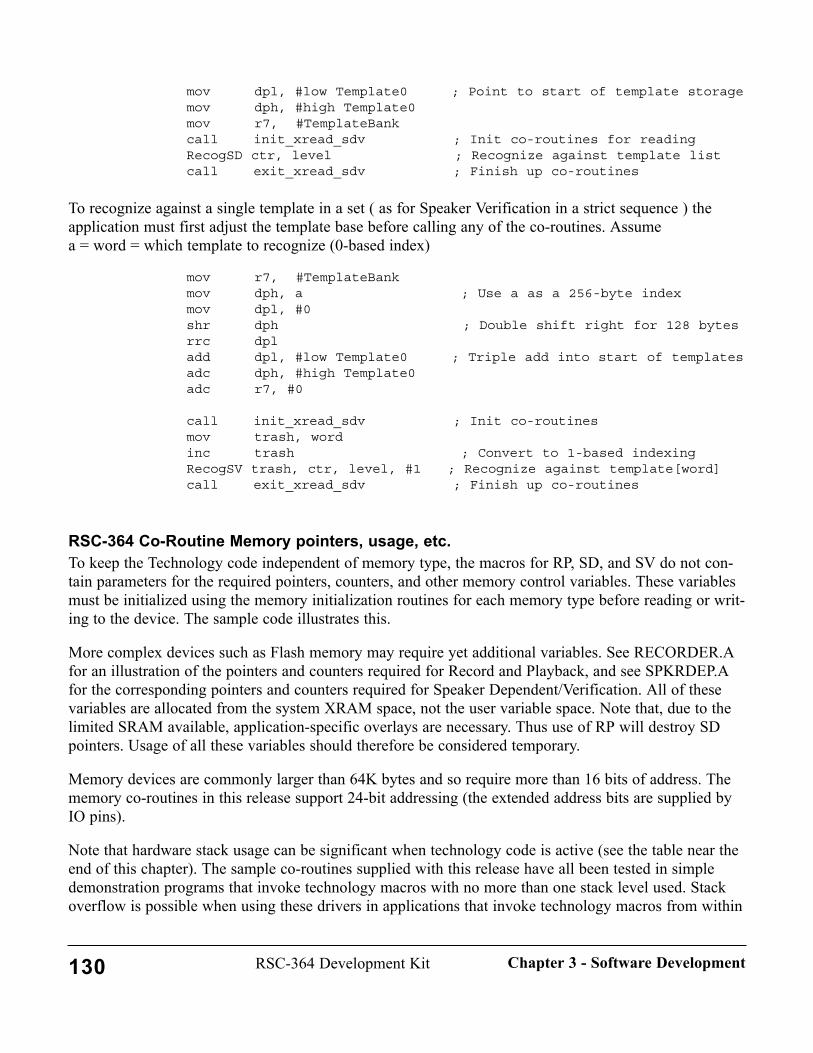
mov dpl, #low Template0 ; Point to start of template storagemov dph, #high Template0mov r7, #TemplateBankcall init_xread_sdv ; Init co-routines for readingRecogSD ctr, level ; Recognize against template listcall exit_xread_sdv ; Finish up co-routines
To recognize against a single template in a set ( as for Speaker Verification in a strict sequence ) theapplication must first adjust the template base before calling any of the co-routines. Assume a = word = which template to recognize (0-based index)
mov r7, #TemplateBankmov dph, a ; Use a as a 256-byte indexmov dpl, #0 shr dph ; Double shift right for 128 bytes rrc dpladd dpl, #low Template0 ; Triple add into start of templatesadc dph, #high Template0adc r7, #0
call init_xread_sdv ; Init co-routinesmov trash, wordinc trash ; Convert to 1-based indexingRecogSV trash, ctr, level, #1 ; Recognize against template[word]call exit_xread_sdv ; Finish up co-routines
RSC-364 Co-Routine Memory pointers, usage, etc.To keep the Technology code independent of memory type, the macros for RP, SD, and SV do not con-tain parameters for the required pointers, counters, and other memory control variables. These variablesmust be initialized using the memory initialization routines for each memory type before reading or writ-ing to the device. The sample code illustrates this.
More complex devices such as Flash memory may require yet additional variables. See RECORDER.Afor an illustration of the pointers and counters required for Record and Playback, and see SPKRDEP.Afor the corresponding pointers and counters required for Speaker Dependent/Verification. All of thesevariables are allocated from the system XRAM space, not the user variable space. Note that, due to thelimited SRAM available, application-specific overlays are necessary. Thus use of RP will destroy SDpointers. Usage of all these variables should therefore be considered temporary.
Memory devices are commonly larger than 64K bytes and so require more than 16 bits of address. Thememory co-routines in this release support 24-bit addressing (the extended address bits are supplied byIO pins).
Note that hardware stack usage can be significant when technology code is active (see the table near theend of this chapter). The sample co-routines supplied with this release have all been tested in simpledemonstration programs that invoke technology macros with no more than one stack level used. Stackoverflow is possible when using these drivers in applications that invoke technology macros from within
130 RSC-364 Development Kit Chapter 3 - Software Development
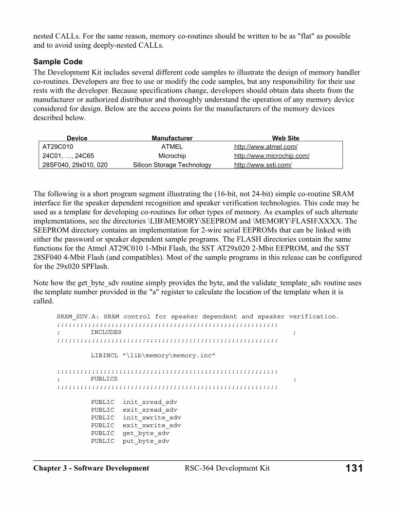
nested CALLs. For the same reason, memory co-routines should be written to be as "flat" as possibleand to avoid using deeply-nested CALLs.
Sample CodeThe Development Kit includes several different code samples to illustrate the design of memory handlerco-routines. Developers are free to use or modify the code samples, but any responsibility for their userests with the developer. Because specifications change, developers should obtain data sheets from themanufacturer or authorized distributor and thoroughly understand the operation of any memory deviceconsidered for design. Below are the access points for the manufacturers of the memory devicesdescribed below.
The following is a short program segment illustrating the (16-bit, not 24-bit) simple co-routine SRAMinterface for the speaker dependent recognition and speaker verification technologies. This code may beused as a template for developing co-routines for other types of memory. As examples of such alternateimplementations, see the directories \LIB\MEMORY\SEEPROM and \MEMORY\FLASH\XXXX. TheSEEPROM directory contains an implementation for 2-wire serial EEPROMs that can be linked witheither the password or speaker dependent sample programs. The FLASH directories contain the samefunctions for the Atmel AT29C010 1-Mbit Flash, the SST AT29x020 2-Mbit EEPROM, and the SST28SF040 4-Mbit Flash (and compatibles). Most of the sample programs in this release can be configuredfor the 29x020 SPFlash.
Note how the get_byte_sdv routine simply provides the byte, and the validate_template_sdv routine usesthe template number provided in the "a" register to calculate the location of the template when it iscalled.
SRAM_SDV.A: SRAM control for speaker dependent and speaker verification.;;;;;;;;;;;;;;;;;;;;;;;;;;;;;;;;;;;;;;;;;;;;;;;;;;;;;;;;;; INCLUDES ;;;;;;;;;;;;;;;;;;;;;;;;;;;;;;;;;;;;;;;;;;;;;;;;;;;;;;;;;;
LIBINCL "\lib\memory\memory.inc"
;;;;;;;;;;;;;;;;;;;;;;;;;;;;;;;;;;;;;;;;;;;;;;;;;;;;;;;;;; PUBLICS ;;;;;;;;;;;;;;;;;;;;;;;;;;;;;;;;;;;;;;;;;;;;;;;;;;;;;;;;;;
PUBLIC init_xread_sdvPUBLIC exit_xread_sdvPUBLIC init_xwrite_sdvPUBLIC exit_xwrite_sdvPUBLIC get_byte_sdvPUBLIC put_byte_sdv
Device Manufacturer Web SiteAT29C010 ATMEL http://www.atmel.com/ 24C01, …, 24C65 Microchip http://www.microchip.com/ 28SF040, 29x010, 020 Silicon Storage Technology http://www.ssti.com/
131RSC-364 Development KitChapter 3 - Software Development
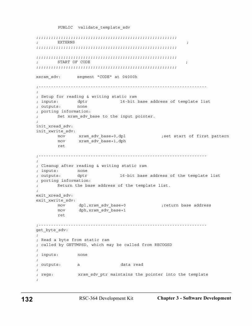
PUBLIC validate_template_sdv
;;;;;;;;;;;;;;;;;;;;;;;;;;;;;;;;;;;;;;;;;;;;;;;;;;;;;;;;;; EXTERNS ;;;;;;;;;;;;;;;;;;;;;;;;;;;;;;;;;;;;;;;;;;;;;;;;;;;;;;;;;;
;;;;;;;;;;;;;;;;;;;;;;;;;;;;;;;;;;;;;;;;;;;;;;;;;;;;;;;;;; START OF CODE ;;;;;;;;;;;;;;;;;;;;;;;;;;;;;;;;;;;;;;;;;;;;;;;;;;;;;;;;;;
xsram_sdv: segment "CODE" at 04000h
;--------------------------------------------------------------------;; Setup for reading & writing static ram; inputs: dptr 16-bit base address of template list; outputs: none; porting information:; Set xram_sdv_base to the input pointer.;init_xread_sdv:init_xwrite_sdv:
mov xram_sdv_base+0,dpl ;set start of first patternmov xram_sdv_base+1,dphret
;--------------------------------------------------------------------;; Cleanup after reading & writing static ram; inputs: none; outputs: dptr 16-bit base address of the template list; porting information:; Return the base address of the template list.;exit_xread_sdv:exit_xwrite_sdv:
mov dpl,xram_sdv_base+0 ;return base addressmov dph,xram_sdv_base+1ret
;--------------------------------------------------------------------get_byte_sdv:;; Read a byte from static ram; called by GETTMPSD, which may be called from RECOGSD;; inputs: none;; outputs: a data read;; regs: xram_sdv_ptr maintains the pointer into the template;
132 RSC-364 Development Kit Chapter 3 - Software Development
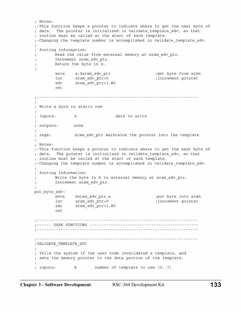
; Notes:;-This function keeps a pointer to indicate where to get the next byte of ; data. The pointer is initialized in validate_template_sdv, so that; routine must be called at the start of each template.;-Changing the template number is accomplished in validate_template_sdv.;; Porting information:; Read the value from external memory at xram_sdv_ptr.; Increment xram_sdv_ptr.; Return the byte in A.;
movx a,@xram_sdv_ptr ;get byte from xraminc xram_sdv_ptr+0 ;increment pointeradc xram_sdv_ptr+1,#0ret
;--------------------------------------------------------------------;; Write a byte to static ram;; inputs: a data to write;; outputs: none;; regs: xram_sdv_ptr maintains the pointer into the template;; Notes:;-This function keeps a pointer to indicate where to get the next byte of ; data. The pointer is initialized in validate_template_sdv, so that; routine must be called at the start of each template.;-Changing the template number is accomplished in validate_template_sdv.;; Porting information:; Write the byte in A to external memory at sram_sdv_ptr.; Increment xram_sdv_ptr.;put_byte_sdv:
movx @xram_sdv_ptr,a ;put byte into xraminc xram_sdv_ptr+0 ;increment pointeradc xram_sdv_ptr+1,#0ret
;--------------------------------------------------------------------;------ USER FUNCTIONS ----------------------------------------------;--------------------------------------------------------------------
;--------------------------------------------------------------------;VALIDATE_TEMPLATE_SDV;; Tells the system if the user code invalidated a template, and; sets the memory pointer to the data portion of the template.;; inputs: A number of template to use (0..?)
133RSC-364 Development KitChapter 3 - Software Development

;; outputs: carry set if the template is not valid; xram_sdv_ptr points to template's data area; A and B can return data to user code;; regs: This routine can alter registers A, B, and trash.; This routine sets xram_sdv_ptr.;; Porting information:; Applications that erase templates without compacting the list; can use this routine to prevent RecogSD from using those templates.; User application code may use this routine for other purposes.;; This routine must set xram_sdv_ptr to the start of the data area; of the selected template before exiting.;validate_template_sdv:
;set xram_sdv_pointer to address of template
mov xram_sdv_ptr+0,#0mov xram_sdv_ptr+1,ashr xram_sdv_ptr+1rrc xram_sdv_ptr+0add xram_sdv_ptr+0,xram_sdv_base+0adc xram_sdv_ptr+1,xram_sdv_base+1
; << Put optional user code here >>; << - Add offset of validation byte >>; << - Test validation byte >>; << - Move pointer to start of data area >>
;xram_sdv_ptr must point to starting address of the data area of ;template 'A' at this point.
;if slot is valid, clear carry bit, else set it
clcret
;--------------------------------------------------------------------
END
Memory Co-Routines Using I2C Serial EEPROMThis release offers full support for development of products using a wide variety of 2-wire (I2C) SerialEEPROMs such as the 24xCxx devices manufactured by Microchip Technology, Inc.
1. The Memory Module contains a 24C65 chip already wired into the circuit.2. The IO.INC file contains default Serial EEPROM ("SEEP") bit assignments.3. The driver supports Speaker Dependent and Speaker Verification applications using devices
134 RSC-364 Development Kit Chapter 3 - Software Development
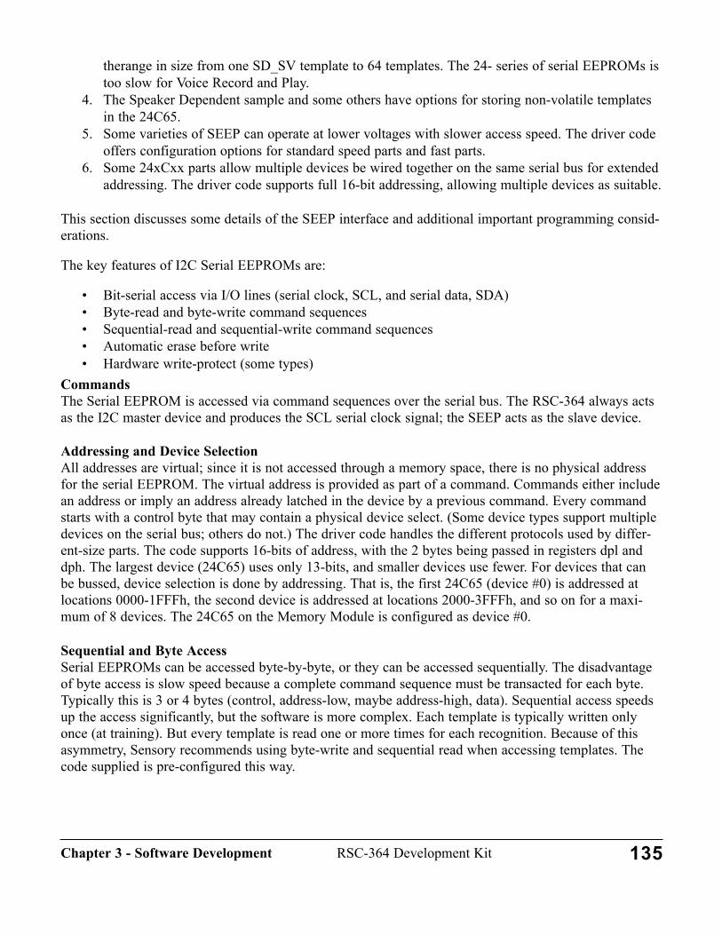
therange in size from one SD_SV template to 64 templates. The 24- series of serial EEPROMs istoo slow for Voice Record and Play.
4. The Speaker Dependent sample and some others have options for storing non-volatile templatesin the 24C65.
5. Some varieties of SEEP can operate at lower voltages with slower access speed. The driver code offers configuration options for standard speed parts and fast parts.
6. Some 24xCxx parts allow multiple devices be wired together on the same serial bus for extendedaddressing. The driver code supports full 16-bit addressing, allowing multiple devices as suitable.
This section discusses some details of the SEEP interface and additional important programming consid-erations.
The key features of I2C Serial EEPROMs are:
• Bit-serial access via I/O lines (serial clock, SCL, and serial data, SDA)• Byte-read and byte-write command sequences• Sequential-read and sequential-write command sequences• Automatic erase before write• Hardware write-protect (some types)
CommandsThe Serial EEPROM is accessed via command sequences over the serial bus. The RSC-364 always actsas the I2C master device and produces the SCL serial clock signal; the SEEP acts as the slave device.
Addressing and Device SelectionAll addresses are virtual; since it is not accessed through a memory space, there is no physical addressfor the serial EEPROM. The virtual address is provided as part of a command. Commands either includean address or imply an address already latched in the device by a previous command. Every commandstarts with a control byte that may contain a physical device select. (Some device types support multipledevices on the serial bus; others do not.) The driver code handles the different protocols used by differ-ent-size parts. The code supports 16-bits of address, with the 2 bytes being passed in registers dpl anddph. The largest device (24C65) uses only 13-bits, and smaller devices use fewer. For devices that canbe bussed, device selection is done by addressing. That is, the first 24C65 (device #0) is addressed atlocations 0000-1FFFh, the second device is addressed at locations 2000-3FFFh, and so on for a maxi-mum of 8 devices. The 24C65 on the Memory Module is configured as device #0.
Sequential and Byte AccessSerial EEPROMs can be accessed byte-by-byte, or they can be accessed sequentially. The disadvantageof byte access is slow speed because a complete command sequence must be transacted for each byte.Typically this is 3 or 4 bytes (control, address-low, maybe address-high, data). Sequential access speedsup the access significantly, but the software is more complex. Each template is typically written onlyonce (at training). But every template is read one or more times for each recognition. Because of thisasymmetry, Sensory recommends using byte-write and sequential read when accessing templates. Thecode supplied is pre-configured this way.
135RSC-364 Development KitChapter 3 - Software Development
RSC on-chip BuffersThe SEEP driver code needs no buffers except in the case of sequential writing. Unfortunately differentdevices have different buffer sizes, which also may vary between manufacturers. If you decide you needthe minimal speed advantage of sequential write, study the manufacturer's data sheet carefully and modi-fy the code accordingly before enabling sequential write.
Hardware and Software Data ProtectionSome of the Serial EEPROM types offer a write protect pin. Some devices offer security options thatallow software write protection of portions of the device. Sensory's code ignores these features.
Memory Co-routines Using "Page Mode" Flash ("sector program mode" EEPROM)This release supports development of products using a number of similar 1- and 2-Mbit Flash Memoriesthat utilize a 128-byte page/sector. The features of these parts are all similar to the Atmel AT29C010, sothese parts are referred to generically as "Atmel".
1. The Memory Module contains PLCC sockets that can accept one of these parts. Socket PLCC-Bhas a 29x020 installed by default.
2. All appropriate code samples have been configured to operate with this type of flash as thedefault.
3. Tested sample driver code is provided (\LIB\MEMORY\FLASH\SPFLASH). This driver containsall the hooks necessary to do both template management and voice recording and playback. Ifyou intend to use this driver we recommend you first gain familiarity by studying the SPKRDEPor RECORDER demo.
4. Several utility functions are provided in the driver module.
This section discusses some details of the Atmel interface and additional important programming consid-erations.
The key features of the Atmel Flash are:
• Parallel access via address and data bus• Byte-read capability• Block-write only, 128-bytes (called a "page" in the code)• Automatic erase before write• Software data protection
The memory handler supplied for the Atmel Flash will also work with the SST equivalent, SST 29x010,the Winbond equivalent, W29x010, and the 2-Mbit equivalent parts, the SST 29x020 and WinbondW29x020. NOTE: Atmel's AT29C020 will not work! This device uses a 256 byte page size, and there isinsufficient SRAM on the RSC for the required buffer.
AddressingThe Atmel (and equivalent) Flash requires a 17-bit address for 128 kbytes (or an 18-bit address for 256kbytes). The low 16 bits of address are transferred to the device via the address bus, and the upper bit(s)is provided by I/O signal(s). The driver code supports 18-bits of address, with the 3 bytes being passed
136 RSC-364 Development Kit Chapter 3 - Software Development
in registers dpl, dph, and r7. The I/O pins assignments for A16 and A17 are made in\LIB\STARTUP\IO.INC. The driver allows these bits to be re-mapped to any I/O pins.
Since the Atmel Flash obtains addresses A0-A15 by the address bus, care must be taken to avoid con-flicts with Data Space page 0XFFXXh, which is used internally by the RSC. The driver code illustratesone way to map around the FF pages.
RSC on-chip BuffersReading is similar to an EPROM or SRAM and requires no buffer. Writing templates is un-bufferedusing the Atmel "byte-load" operation (also similar to writing to SRAM). Since all the data are availableat the start, the code can simply stream the data to the Flash at a rate fast enough (<150 (sec per byte) toassure that the Flash does not begin its automatic internal programming cycle until all bytes have beenwritten.
Speech samples during Voice Recording are available at a speed (approximately 250 (sec per sample)too slow to allow use of the byte-load approach, so writing Voice Recording data to the Atmel Flashrequires buffered writes. The large (128-byte) write sector size of the Atmel requires great care in allo-cating the RAM buffer. It happens that RSC RAM banks C through F are available during the voicerecording operation, so these banks are used for the sector buffer. Note that these specific banks are notavailable when other technology code is active.
Software Data ProtectionThe driver code contains a macro, DO_SDP_HEADER, that is used to prevent accidental writes to theAtmel Flash. The macro is invoked before every sector write to disable write protection temporarily.Protection is automatically restored after the write.
Memory Co-routines Using 4-Mbit SST FlashThis release incorporates support for development of products using the Silicon Storage Technology SST28SF040 4-Mbit SuperFlash EEPROM ("SST Flash"):
1. Sample co-routine driver code (but not complete sample programs) for the chip (\LIB\MEMO-RY\FLASH\SST). These drivers provide all the hooks necessary to do template management orvoice recording and playback. If you intend to use these drivers we recommend you first gainfamiliarity by attaching the driver to the SPKRDEP or RECORDER demo.
2. The IO.INC file contains default SST Flash extended address bit assignments. These may bemodified as required.
3. The driver files contain a description of the modifications to the Memory Module required to usethe SST Flash.
4. Socket PLCC-B can accommodate the PLCC package version of this device, making it easy to develop with no modification to the Memory Module.
The SST code illustrates adding wait states during read access to allow use of slow (280 nsec) parts.
This section discusses some details of the SST interface and additional important programming consider-ations.
137RSC-364 Development KitChapter 3 - Software Development

The key features of the SST Flash are:
• Parallel access via address and data bus• Byte-read capability• Byte-write capability• Erase-before-write required, 256 byte erase block
AddressingThe SST Flash requires a 19-bit address for 512 kbytes. The low 16 bits of address are transferred to thedevice via the address bus, and bits A16-A18 are provided by I/O signals. The code supports 19-bits ofaddress, with the 3 bytes being passed in registers dpl, dph, and r7. Extension to larger parts is straight-forward with additional I/O pin assignments.
Since the SST Flash obtains addresses A0-A15 by the address bus, care must be taken to avoid conflictswith Data Space page 0XFFXXh, which is used by the RSC. The code to map around the FF pages iscontained inline at the top of the routines where it is needed. The driver allows the three address exten-sion bits to be re-mapped to any I/O pins (see IO.INC).
RSC on-chip BuffersReading with the SST SuperFlash is similar to an EPROM. Commands are used to initiate other memoryoperations. Write operations ("byte_program") consist of a command byte and one data byte. No bufferis required.
A byte must be erased before it can be programmed. Utility routines are provided to erase by sectors(256 bytes) or to erase the entire chip. No buffering is required.
Software Data ProtectionThe SST powers up with active software data protection to prevent accidental writes. The driver codecontains a subroutine, FLASH_INITIALIZE, that removes the software data protection. Minor modifica-tion of this code (shown in comments) allows re-enabling software data protection.
9. Using the BootloaderA 264T or 364 Development Kit can be configured to emulate a Demo Unit 264T or 364 by selectingPC DOWNLOAD mode on the Memory Module. In this mode, the development kit hardware functionsidentically to the hardware found on the Demo Unit, allowing evaluation of the demonstration programsand use of the bootload facility. This section describes the bootload process on the Development Kithardware. See separate documentation for using the bootloader on the Demo Unit.
In this document, commands to be typed by the user are shown in bold. For help when using the bootload.exe program, type:
C:>BOOTLOAD ?
The bootload program, BOOTLOAD.EXE, is placed in the \BIN library by the RSC-364 DevelopmentKit installation process. Running under DOS, this file will reference the current directory for its data file.
138 RSC-364 Development Kit Chapter 3 - Software Development

As described elsewhere, the \LIB directory must be in your path.
How to start the boot loader and connect it to the PC:
1. Using a serial cable, connect the serial port of the Development Kit to the serial port of the PC. 2. Make sure the Boot Load OTP is installed in socket PLCC-A, the Sample Flash is installed in
socket TSOP-B, and the PC_DOWNLOAD jumper, JB4, is installed. Remove any asjacentjumpers.
3. While holding down the BOOT button (located on the Memory Module near the rotary PRO-GRAM SELECT switch), press and release the RESET button (the button nearest the RSC-364chip). If the boot loader program in the Boot Load OTP successfully started, you will hear abeep and the Green LED and LEDs 1 and 8 will light. Release the BOOT switch after the beep.
4. Type "bootload" at the DOS prompt on your PC. Press Enter or Return. The boot loaderdefaults to com port 2, at 115,200 baud. The baud rate CANNOT be changed from 115,200baud. To use com port 1, at the prompt type:
C:\ bootload -P1 -B115
5. If the boot loader successfully communicated with the PC, the Yellow LED will turn on, and thePC screen will read:
Initializing communication on port 2 at 115200 baud...
Boot LoaderRSC 364
Version 1.2Sensory, Inc.
(D)ownload to RPM or (U)pload from RPM?
The version number might be different if you use a Demo Unit. If the boot loader did not start correctly, see below for possible causes.
6. To download new code or data into the Memory Module, press "d". Press Enter or Return.
• The PC program will prompt for the type of memory device to download into. To download a new program into the Sample Flash, select code space.
Download to (C)ode space, (D)ata space, or (S)EEPROM?
To download to code space (Sample Flash), press "c". To download into data space (SPFlash), press "d". To download into the serial EEPROM, press "s". Press Enter or Return.
139RSC-364 Development KitChapter 3 - Software Development

• If you selected code space or data space (Flash), the program will prompt for the sector to download into:
Select code space sector (0-7):
If downloading to the Sample Flash, rotate the PROGRAM SELECT switch on the Memory Module tothe number of the program sector where you wish to download the new program. Enter the correspon-ding sector number at the PC prompt (eg. "0"), and press Enter or Return.
• For downloading to code space, data space or serial EEPROM, the PC program will then prompt for an input file. This should be a binary image of the data to be loaded into the memorydevice:
Enter name of file to read:
Type in the name of the file that you want to download. If the file is in the same directory that youcalled the bootload.exe program from, you can simply type in the file name (eg. "code.bin"). If the fileis in another directory, you must type in the path of the file relative to the directory from where boot-load.exe was called. Press Enter or Return after typing in the file name.
• The PC program will report the current download settings, and the progress of the download. After approximately 40 seconds, the program will beep twice, indicating a successful download. (Sectors 0 and 7 take a little longer). The "RPM" comment refers to Sensory's Rapid Prototyping Board, a small hardware platform useful for prototyping.
Downloading c:\sensory\fddemo\code.bin to RPM code space, sector0................................................................................................................................................................................................................................................................................................................................................................................................................................................................................................................................Download completed successfully.
7. To upload data from the Memory Module (from data space SPFlash or serial EEPROM only),press "u". Press Enter or Return.
• The PC program will prompt for the type of memory device to upload from. Data can only be uploaded from the data space Flash memory, or the serial EEPROM. It CANNOT be uploaded from the code space Sample Flash (where programs reside).
Upload from (D)ata space or (S)EEPROM?
To upload from data space Flash, press "d". To upload from the serial EEPROM, press "s".Press Enter or Return.
• If you selected data space, the program will prompt for the sector to upload from:
140 RSC-364 Development Kit Chapter 3 - Software Development
Select data space sector (0-3):
Enter the corresponding number at the PC prompt (eg. "0"), and press Enter or Return.
• The PC program will then prompt for a target filename. This file will be created by the PC program, and will be a binary image of the data retrieved from the memory device. NOTE: the PC program will overwrite any file of the same name as the file specified as the output target file.
Enter name of file to write:
Type in the name of the file that you want to upload into. If the file is in the same directory thatyou called the bootload.exe program from, you can simply type in the file name (eg. "code.bin").If the file is in another directory, you must type in the path of the file relative to the directoryfrom where bootload.exe was called. Press Enter or Return after typing in the file name.
• The PC program will report the current upload settings, and the progress of the download. After approximately 10 seconds, the program will beep twice, indicating a successful upload.
Uploading RPM data space, sector 0, to
test.bin................................................................................................................................................................................................................................................................................................................................................................................................................................................................................................................................
Upload completed successfully.
Troubleshooting TipsIf the boot loader does not work, check the following items:
• The 9 pin RS232 cable is correctly and firmly plugged into the computer and the Motherboard.• The Boot Load OTP is installed correct in socket PLCC-A• The Sample Flash is installed correctly in socket TSOP-B.• The JB4 PC_DOWNLOAD jumper is installed and other adjacent jumpers are removed.• The unit was reset with the BOOT switch held down.• The Program Select knob is rotated to the correct number.• The correct port setting was used in the command to start the bootloader• The computer supports serial communications at 115,200 baud.
NOTICEThe Bootloader program can appear to lose data when uploading or downloading to the Data Space flash(SPFlash) in socket PLCC-B. Contact Sensory for assistance when attempting to upload or download tothat device. Bootload works reliably for writing to the Sample Flash and reading and writing the SerialEEPROM.
141RSC-364 Development KitChapter 3 - Software Development
10. Building Multi-Bank SystemsApplications using large amounts of speech or very large program code may require managing memorylarger than the 16-bit addressing capability of the RSC-364. Such applications must use Bank Switching.Physically, bank switching is accomplished by using one or more I/O pins to act as extended address bitsfor larger memories. Most applications larger than 64K need abundant storage for synthesis data orrecognition weights, but may require less than 64K of executable code. These applications can be imple-mented using only Data Space placement of speech data and SI recognition weights (see Banked DataSpace below).
Programs requiring more than 64K of executable code must use ROM Code Bank switching. In Release6, Sensory does not support ROM Code Bank Switching on the RSC-364. Only ROM Data BankSwitching is supported. Therefore any developer requiring ROM Code Bank switching will have toimplement the required mechanisms (subroutine jump and return tables, interrupt vectors, parameterpassing, etc). It is recommended to contact Sensory before beginning such a development effort.
Banked Data SpaceThe simplest multi-bank system has all the executable code in one 64K Code Space ROM and data(only) in one or more additional banks. The additional banks are mapped to Data Space, selected by I/Opins. This configuration is referred to as "Data Space placement" of weights and synthesis data (or otherapplication-specific fixed data). The RSC-364 Developer Kit supports configurations of this type aslarge as 4 Megabits requiring only one inexpensive external decoder IC. Larger systems may be builtwith slight additional decoding. The general approach is the following:
• The executable code is placed in the lowest 64K bank of the extended address space.• The ROM output_enable pin is enabled by either the -RDC signal or the -RDD signal. This
assures that the ROM is accessed by code fetches as well as movc and movx instructions.• The extended address bits of the ROM (A16, A17, A18) are logically conditioned to be driven
by bank-selection I/O pins whenever the -RDD signal is active (low), but driven to 0 whenever the -RDC signal is active. This assures that the lowest bank is accessed by code fetches and movc instructions, and the other banks are accessed by movx instructions.
• The speech and weights "handlers" are configured to supply data from Data Space.• If the application requires read/write Data Space memory (for example Flash to store a voice
recording), additional decoding must be implemented to choose the correct device when reading from Data Space.
The figure below illustrates an example of a 4 Mbit application with no external read/write memory. Theexample shows that the 64K bytes of code space is programmed in the lowest bank (address 00000h ~0FFFFh), and data space is programmed into the upper banks (address 10000 ~ up to 3FFFFh). P0.2,P0.3, and P0.4 are used for A16, A17, and A18 respectively for the standard extended address bus.
When the RSC364 reads "code" from the memory IC, the RDC signal goes low. The logic shown in theexample will select the lowest bank by forcing A16, A17, and A18 to go low, and it will enable the ICand its outputs for the "code" to be read.
142 RSC-364 Development Kit Chapter 3 - Software Development

When "data" need to be read, the RDD signal goes low. It will select one of the upper banks by enablingthe extended standard address bus of A16, A17, and A18. NOTE: This simple design works only if thereis no external read/write memory. The requirement for Flash, SRAM, or other data space device requiresadditional decoding.
In the example shown, any one of sockets (DIP, PLCC-A, and PLCC-B) or TSOP-A can be used for amulti-bank program. (PLCC-A is limited to 2Mbit).
To Use PLCC-A for 2Mbit OTP such as AT27C020-12TC:
• Remove a shorting block from JB4, JB6, JB2, or JB3 if there is any.• Data bus and Address A0 ~ A15 are already connected to PLCC-A• Install a 74HC08 in one of three 14-pin DIP sockets (U15, U16, U17), and solder the hook-up
wires from TH2: PORT and TH9: CONTROL to the 74HC08.• Solder the hook-up wire from the 74HC08 to TH3: PLCC-A.
The RSC-364 assembler and linker can deal with only 64Kbytes, so the entire application must be builtin sections of this size. Each Data Space bank must be built separately, and data may not "wrap" fromone bank to the next. The application must explicitly select the bank control bits before calling synthesisor recognition. Remember also that the last page of each Data Space bank (addresses xFFxxh) is mappedinternally in the RSC-364 and is not accessible externally.
As an illustration of this software method, the CLSI demo can be configured to allow Data Space place-ment of the weights and speech data.
See also Memory Module Configuration, RAM Allocation, and Allocating ROM for Speech andWeights in the Overview section.
143RSC-364 Development KitChapter 3 - Software Development
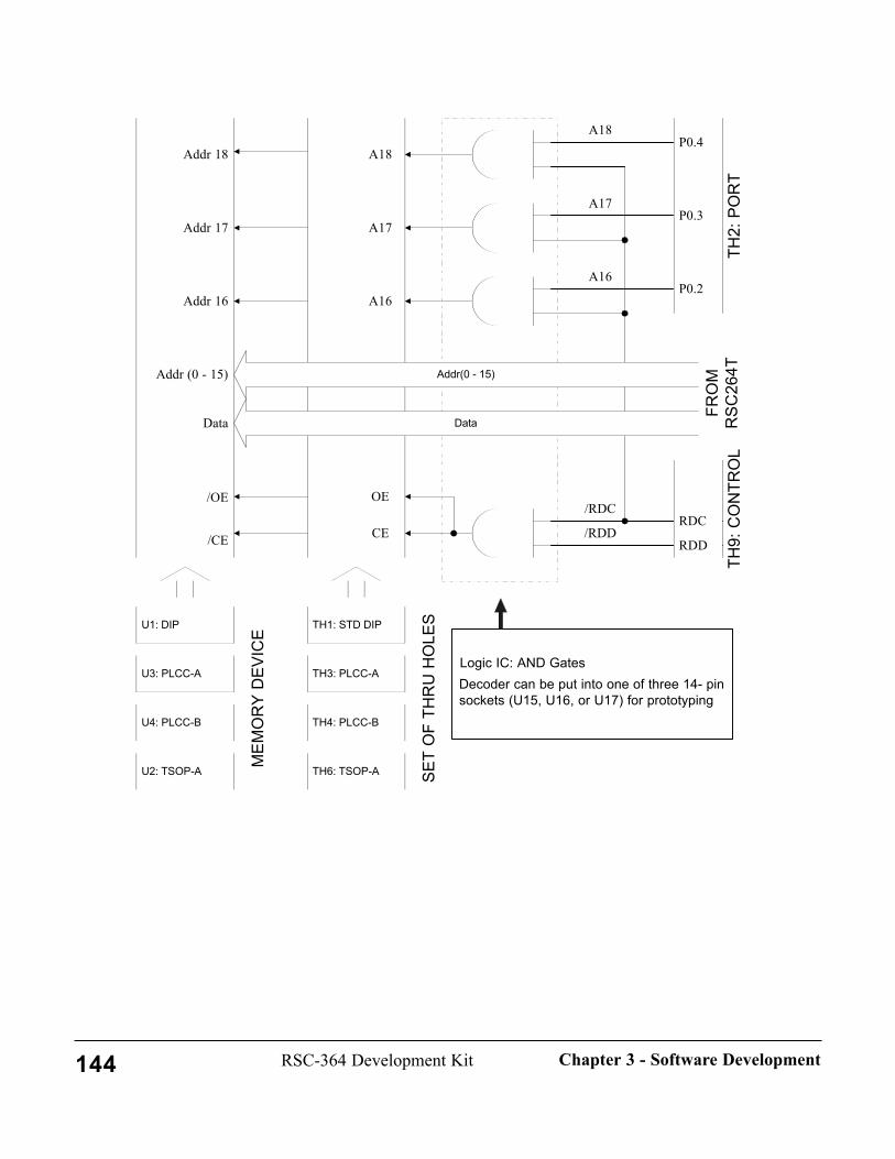
Addr (0 - 15)
Addr 16
Data
/CE
/OE
Addr 17
Addr 18P0.4
P0.3
P0.2
RDD
RDC
Data
Addr(0 - 15)
TH9:
CO
NTR
OL
TH2:
PO
RT
FRO
MR
SC26
4T
A18
A17
A16
/RDC
/RDD
A16
A17
A18
OE
CE
U1: DIP TH1: STD DIP
U3: PLCC-A TH3: PLCC-A
U4: PLCC-B TH4: PLCC-B
U2: TSOP-A TH6: TSOP-A SET
OF
THR
U H
OLE
S
MEM
OR
Y D
EVIC
E
Logic IC: AND GatesDecoder can be put into one of three 14- pinsockets (U15, U16, or U17) for prototyping
144 RSC-364 Development Kit Chapter 3 - Software Development

11. Using the Floating Point Library RoutinesSensory's technology code uses a library of floating point math routines. This section documents the for-mat and usage of that software for the developer whose application also needs floating point. The float-ing-point software is available in object code form in the directory \LIB364\UTIL. The file\LIB\UTIL\SAMPLEFP.TXT contains code snippets illustrating usage of the FP routines.
InitializationNo special initialization is required to use the FP routines.
IncludesThe FP routines are accessed via CALL functions rather than by macros. Applications should LIBINCLthe file \LIB\UTIL\FPCONST.INC to define the required bit definitions. If you use integer multiply ordivide, LIBINCL the file \LIB\UTIL\MATH.INC.
The FP routines use some memory locations that are defined in MEMORY.INC, so this file must beINCLUDE'd in the application program. See Using the RSC-364 Memory Map for detailed information.
LinkingLink the application code with the modules \LIB364\UTIL\INTMATH.O (to include integer multiply ordivide) and \LIB364\UTIL\FLOAT2.O. If you use the integer routines, be sure to read the comments in\LIB\UTIL\MATH.INC.
FunctionsThe floating-point library maintains an internal floating-point accumulator (FAC). The FAC is notaccessed directly. Instead values are loaded into the FAC using the LDFAC function and stored from theFAC using the STFAC function. 4-byte floating-point operands are referenced with the DPTR pseudo-register pair (DPL, DPH). Floating-point operands are assumed to reside in internal data RAM unless theFACRNM bit is set in the FACBIT byte. If FACRNM is set, the operand is in code space. FACBIT isstored in the technology portion of internal RAM and includes the following bits:
FACSGN equ 80h ; Sign of value in FACFACBTM equ 40h ; Bit temporaryFACRNM equ 20h ; Flag to signal ROM resident con-stantNANFLG equ 10h ; Not-A-Number Result FlagOVFFLG equ 08h ; Overflow (Infinite) Result FlagUNFFLG equ 04h ; Underflow Result Flag
The two least significant bits are reserved for result codes. They are zero if the operation was successful.Otherwise they are set as follows:
ERUNF equ 1 ; FPERR underflow error codeEROVF equ 2 ; FPERR overflow error codeERNAN equ 3 ; FPERR invalid operation error code
Floating-point results are always placed in the floating-point accumulator, FAC. Integer operands and
145RSC-364 Development KitChapter 3 - Software Development
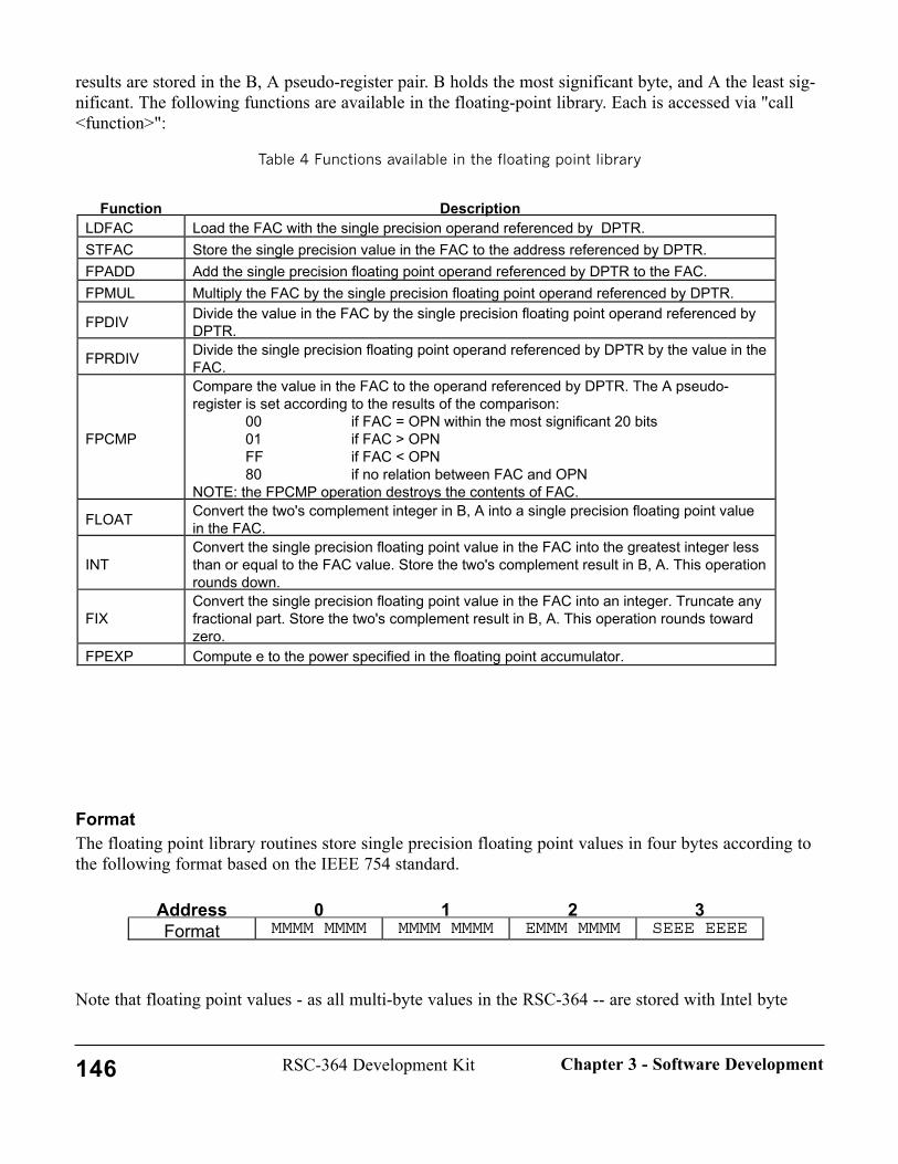
results are stored in the B, A pseudo-register pair. B holds the most significant byte, and A the least sig-nificant. The following functions are available in the floating-point library. Each is accessed via "call<function>":
Table 4 Functions available in the floating point library
FormatThe floating point library routines store single precision floating point values in four bytes according tothe following format based on the IEEE 754 standard.
Note that floating point values - as all multi-byte values in the RSC-364 -- are stored with Intel byte
Address 0 1 2 3Format MMMM MMMM MMMM MMMM EMMM MMMM SEEE EEEE
Function DescriptionLDFAC Load the FAC with the single precision operand referenced by DPTR.STFAC Store the single precision value in the FAC to the address referenced by DPTR.FPADD Add the single precision floating point operand referenced by DPTR to the FAC.FPMUL Multiply the FAC by the single precision floating point operand referenced by DPTR.
FPDIV Divide the value in the FAC by the single precision floating point operand referenced byDPTR.
FPRDIV Divide the single precision floating point operand referenced by DPTR by the value in theFAC.
FPCMP
Compare the value in the FAC to the operand referenced by DPTR. The A pseudo-register is set according to the results of the comparison:
00 if FAC = OPN within the most significant 20 bits01 if FAC > OPNFF if FAC < OPN80 if no relation between FAC and OPN
NOTE: the FPCMP operation destroys the contents of FAC.
FLOAT Convert the two's complement integer in B, A into a single precision floating point valuein the FAC.
INTConvert the single precision floating point value in the FAC into the greatest integer lessthan or equal to the FAC value. Store the two's complement result in B, A. This operationrounds down.
FIXConvert the single precision floating point value in the FAC into an integer. Truncate anyfractional part. Store the two's complement result in B, A. This operation rounds towardzero.
FPEXP Compute e to the power specified in the floating point accumulator.
146 RSC-364 Development Kit Chapter 3 - Software Development

ordering (i.e., most significant bytes at highest addresses).
The bit fields making up the floating point value are interpreted as follows:
Several special values are also defined:
AccuracyFloating-point results were compared against results obtained using the Borland C++ version 4.0 mathroutines. In general the results agreed. One test case in the addition test disagreed in the least significantbit. In this case a higher precision calculation would have had a one in the next least significant bit, andzeroes in all succeedingly less significant bit. Borland seems to round this down; the FPADD routinerounds up. All other test results agreed with the Borland library except for exponentiation (FPEXP).Most results had errors in at most the least significant one or two bits. One case however differed in theleast significant six bits. This still provides 18 bits of significance, which should be adequate for mostapplications.
Memory UsageThe floating-point library uses a variety of RAM locations to store the floating-point accumulator,FACBIT, and other temporary storage locations. All of these locations are overlaid with other technologycode when floating point is not being used. Thus the floating-point memory is not free and available inapplications not using floating point. The ROM requirement for the routines is about 3K bytes.
SPECIAL VALUE S EEEE EEEE MMM MMMM MMMM MMMM MMMM MMMM
Zero 0 0 0 (no implicit 1 in most significant bit)Signed Infinity 0 or 1 0FFH 0 (no implicit 1 in most significant bit)Not a Number(NaN)
don't care(usually 1) 0FFH non-zero (usually 7FFFFFH)
S Sign bit: 1 if negative, 0 otherwise.
EEEE EEEEBase 2 exponent biased by 127 decimal. 0 and 255are reserved for special values (see below).Therefore: -126 ≤ exponent ≤ 127
MMM MMMM MMMM MMMM MMMM MMMM
23 bit normalized mantissa with an implicit 1 in themost significant position (24th bit). A binary point isassumed after the implicit 1 in the most significantposition. Therefore: 1.0 ≤ mantissa < 2.0.
147RSC-364 Development KitChapter 3 - Software Development
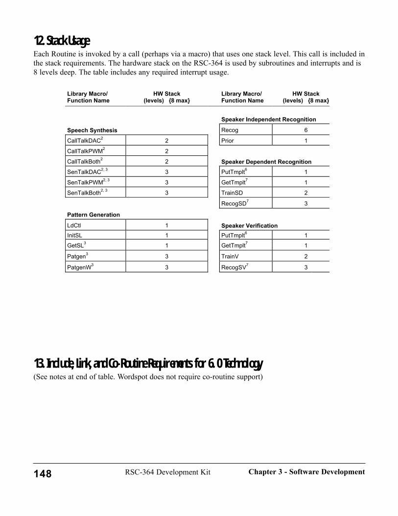
12. Stack UsageEach Routine is invoked by a call (perhaps via a macro) that uses one stack level. This call is included inthe stack requirements. The hardware stack on the RSC-364 is used by subroutines and interrupts and is8 levels deep. The table includes any required interrupt usage.
13. Include, Link, and Co-Routine Requirements for 6. 0 Technology (See notes at end of table. Wordspot does not require co-routine support)
Library Macro/Function Name
HW Stack(levels) 8 max
Library Macro/Function Name
HW Stack(levels) 8 max
Speaker Independent Recognition
Speech Synthesis Recog 6
CallTalkDAC2 2 Prior 1
CallTalkPWM2 2
CallTalkBoth2 2 Speaker Dependent RecognitionSenTalkDAC2, 3 3 PutTmplt6 1
SenTalkPWM2, 3 3 GetTmplt7 1
SenTalkBoth2, 3 3 TrainSD 2
RecogSD7 3
Pattern Generation
LdCtl 1 Speaker VerificationInitSL 1 PutTmplt6 1
GetSL3 1 GetTmplt7 1
Patgen3 3 TrainV 2
PatgenW3 3 RecogSV7 3
148 RSC-364 Development Kit Chapter 3 - Software Development

Technology Used
Include .INC (\libxxx\macros\)
Link .O (\libxxx\)
Co-routines Required1
All Applications using technology code
Analog.o delay14.o const364.o
Pattern Generation patgen Patgen\patgen PatgenHandler3 memory Patgen\block PatgenMemDriver3 Patgen\digagc Patgen\stream Patgen\nulogfns Patgen\normal Speaker Independent si si\recog RecogMemDriver13 Recognition memory util\intmath RecogMemDriver23 util\float2
si\prior7
Speaker Dependent sdsv util\intmath init_xread_sdv Recognition memory sd_sv\sd init_xwrite_sdv memory\xram sd_sv\template exit_xread_sdv Speaker Verification sdsv sd_sv\sdweight exit_xwrite_sdv memory sd_sv\svweight get_byte_sdv memory\xram sd_sv\onchip2 put_byte_sdv sd_sv\auxtmplt2 validate_template_sdv Continuous Listening patgen cl\cntlstn PatgenHandler3 cntlstn Patgen\patgen PatgenMemDriver3 memory Patgen\block cl_busy3
Patgen\digagc cl_ready3
Patgen\stream cl_done3
Patgen\nulogfns Patgen\normal Voice Record and rp rp\rec stop_rp_play3 Play memory rp\play stop_rp_record3 \lib\xram_rp rp\post init_xread_rp memory\xram rp\cmp4 init_xwrite_rp rp\mem_rp exit_xread_rp rp\3bit2bit4 exit_xwrite_rp rp\rp3bit4 get_byte_rp rp\rp2bit4 put_byte_rp get_byte_tmp set_tmpptr_getptr set_ getptr_tmpptr set_putptr_putend add_getptr sub_getptr add_tmpptr cp_tmpptr_getptr
149RSC-364 Development KitChapter 3 - Software Development
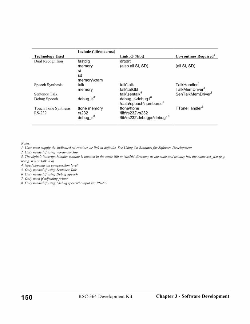
Notes:1. User must supply the indicated co-routines or link in defaults. See Using Co-Routines for Software Development2. Only needed if using words-on-chip3. The default interrupt handler routine is located in the same \lib or \lib364 directory as the code and usually has the name xxx_h.o (e.g.recog_h.o or talk_h.o) 4. Need depends on compression level5. Only needed if using Sentence Talk6. Only needed if using Debug Speech7. Only need if adjusting priors8. Only needed if using "debug speech" output via RS-232.
Technology Used
Include (\lib\macros\) Link .O (\lib\)
Co-routines Required1
Dual Recognition fastdig drt\drt memory (also all SI, SD) (all SI, SD) si sd memory\xram Speech Synthesis talk talk\talk TalkHandler3 memory talk\talktbl TalkMemDriver3 Sentence Talk talk\sentalk5 SenTalkMemDriver3 Debug Speech debug_s6 debug_s\debug16 \data\speech\numbersd6 Touch Tone Synthesis ttone memory ttone\ttone TToneHandler3 RS-232 rs232
debug_s8 \lib\rs232\rs232 \lib\rs232\debugpc\debug18
150 RSC-364 Development Kit Chapter 3 - Software Development

151RSC-364 Development KitChapter 3 - Software Development
152
CHAPTER 4 - HARDWARE
This chapter contains the schematics and parts locator drawings for the DK264T/364Motherboard, DK264T/364 Memory Module, DK264T/364 IO Module, and DialerKeypad. These reference documents are provided to allow the developer to readily inter-face to the Development Modules and to perform hardware and software debugging.
It also provides the connector pin specifications on for each of the Development Kitboards.
1. DK264T/364 Motherboard Schematic DK264T/364 Motherboard Schematic (Check the inside front cover of this manual for this drawing).
2. DK264T/364 Motherboard Parts Locator2. DK264T/364 Motherboard Parts Locator
153RSC-364 Development KitChapter 4 - Hardware

154 RSC-364 Development Kit Chapter 4 - Hardware

3. DK264T/364 Memory Module SchematicDK264T/364 Memory Module Schematic 1(Check the inside the front cover of this manual for this drawing).
4. DK264T/364 Memory Module Schematic-2DK264T/364 Memory Module Schematic-2 (Check the inside front cover of this manual for this drawing).
5. K264T/364 Memory Module Parts Locator K264T/364 Memory Module Parts Locator
155RSC-364 Development KitChapter 4 - Hardware

156 RSC-364 Development Kit Chapter 4 - Hardware
6. DK264T/364 I/O Module Schematic-26. DK264T/364 I/O Module Schematic-2
157RSC-364 Development KitChapter 4 - Hardware

70-0043
Sensory, Inc.
A
1Thursday, January 07, 1999
Title
Size Document Number
Date: Sheet
VDD VDD
P0.5P0.7
P1.7
P0.4
P1.4
/XMH
PDN
/XML
P0.1P0.3
P1.1P1.3P1.5
P0.2
P0.6P1.0P1.2
P1.6
PWM1
P0.0
EXTXI2
/RST
EXTXI1
PWM0
VDDP1.0P1.1P1.2P1.3P1.4P1.5P1.6P1.7GND
VDDP0.0P0.1P0.2P0.3P0.4P0.5P0.6P0.7
GND
JP1
EC16X2A16 B16A15 B15A14 B14A13 B13A12 B12A11 B11A10 B10A9 B9A8 B8A7 B7A6 B6A5 B5A4 B4A3 B3A2 B2A1 B1
JP2
HEADER 10X2
1 23 45 67 89 1011 1213 1415 1617 1819 20
EXTXI1EXTXI2XMLXMHPWM1PWM0RSTPDN
P0.0P0.1
P0.3P0.2
P0.5P0.4
P0.7P0.6
P1.7
P1.0P1.1
P1.3
P1.5P1.4
P1.2
P1.6
GNDGNDGND
VDDVDDVDD
VDDGND
DK264T/364 IO Module
THROUGH HOLES
158R
SC-364 D
evelopment K
itC
hapter 4 - Hardw
are
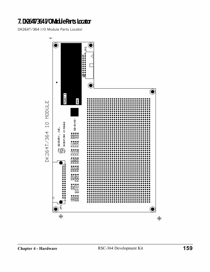
7. DK264T/364 I/O Module Parts LocatorDK264T/364 I/O Module Parts Locator
159RSC-364 Development KitChapter 4 - Hardware
8. Dialer Keypad SchematicDialer Keypad Schematic
160 RSC-364 Development Kit Chapter 4 - Hardware
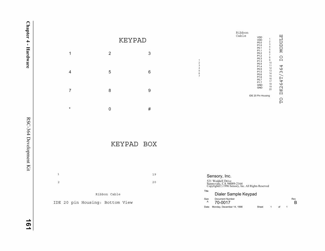
70-0017 B
Sensory, Inc.521 Weddell DriveSunnyvale, CA 94089-2164Copyright(C) 1996 Sensory, Inc. All Rights Reserved
A
1 1Monday, December 14, 1998
Dialer Sample KeypadTitle
Size Document Number Rev
Date: Sheet of
VDDVDDP0.0P1.0
P0.2P1.2P0.3P1.3P0.4P1.4P0.5P1.5P0.6P1.6P0.7P1.7GNDGND
P1.1P0.1
1 2 3
4 5 6
7 8 9
#0*
1234567
IDE 20 Pin Housing
1234567891011121314151617181920
KEYPAD
KEYPAD BOX
TO DK264T/364 IO MODULE
RibbonCable
Ribbon Cable
1
2 20
19
IDE 20 pin Housing: Bottom View
161R
SC-364 D
evelopment K
itC
hapter 4 - Hardw
are
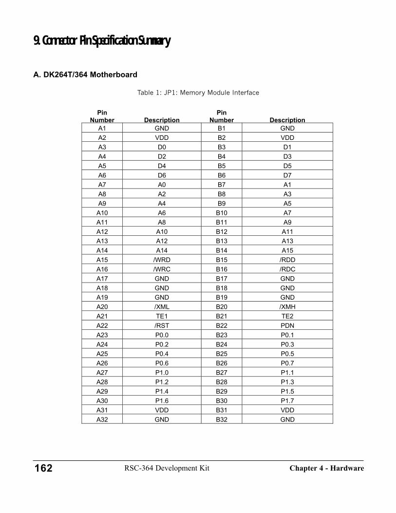
9. Connector Pin Specification Summary
A. DK264T/364 Motherboard
Table 1: JP1: Memory Module Interface
PinNumber Description
PinNumber Description
A1 GND B1 GNDA2 VDD B2 VDDA3 D0 B3 D1A4 D2 B4 D3A5 D4 B5 D5A6 D6 B6 D7A7 A0 B7 A1A8 A2 B8 A3A9 A4 B9 A5A10 A6 B10 A7A11 A8 B11 A9A12 A10 B12 A11A13 A12 B13 A13A14 A14 B14 A15A15 /WRD B15 /RDDA16 /WRC B16 /RDCA17 GND B17 GNDA18 GND B18 GNDA19 GND B19 GNDA20 /XML B20 /XMHA21 TE1 B21 TE2A22 /RST B22 PDNA23 P0.0 B23 P0.1A24 P0.2 B24 P0.3A25 P0.4 B25 P0.5A26 P0.6 B26 P0.7A27 P1.0 B27 P1.1A28 P1.2 B28 P1.3A29 P1.4 B29 P1.5A30 P1.6 B30 P1.7A31 VDD B31 VDDA32 GND B32 GND
162 RSC-364 Development Kit Chapter 4 - Hardware
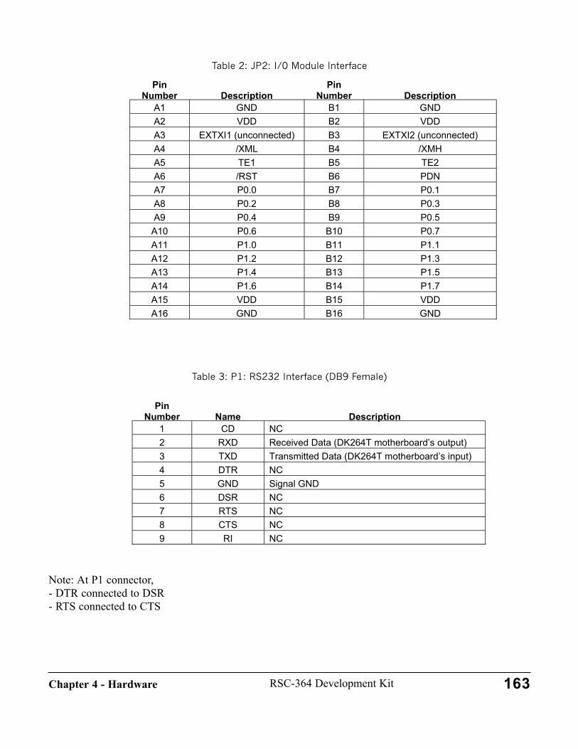
Table 2: JP2: I/0 Module Interface
Table 3: P1: RS232 Interface (DB9 Female)
Note: At P1 connector, - DTR connected to DSR- RTS connected to CTS
PinNumber Name Description
1 CD NC2 RXD Received Data (DK264T motherboard’s output)3 TXD Transmitted Data (DK264T motherboard’s input)4 DTR NC5 GND Signal GND6 DSR NC7 RTS NC8 CTS NC9 RI NC
PinNumber Description
PinNumber Description
A1 GND B1 GNDA2 VDD B2 VDDA3 EXTXI1 (unconnected) B3 EXTXI2 (unconnected)A4 /XML B4 /XMHA5 TE1 B5 TE2A6 /RST B6 PDNA7 P0.0 B7 P0.1A8 P0.2 B8 P0.3A9 P0.4 B9 P0.5A10 P0.6 B10 P0.7A11 P1.0 B11 P1.1A12 P1.2 B12 P1.3A13 P1.4 B13 P1.5A14 P1.6 B14 P1.7A15 VDD B15 VDDA16 GND B16 GND
163RSC-364 Development KitChapter 4 - Hardware

J4: Power Input (Right Angle 2-pin Header)
J1: Microphone Input (Phone Jack)
J2: Audio Output: PWM (Phone Jack)
J3: Audio Output: Speaker (Phone Jack)Amplified DAC output
J5: Audio Output: DAC (Straight 2-pin Header)Un-amplified DAC output
B. DK264T/364 Memory Module
PinNumber Description
PinNumber Description
1 Power 2 GND
164 RSC-364 Development Kit Chapter 4 - Hardware
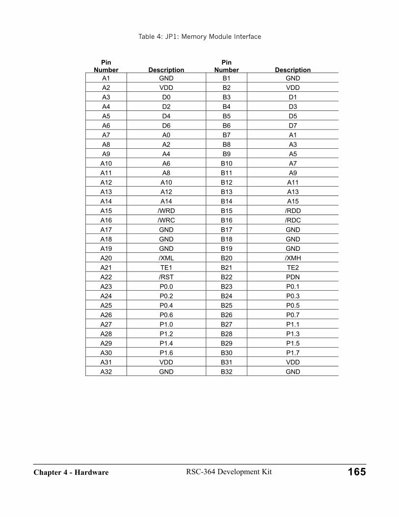
Table 4: JP1: Memory Module Interface
PinNumber Description
PinNumber Description
A1 GND B1 GNDA2 VDD B2 VDDA3 D0 B3 D1A4 D2 B4 D3A5 D4 B5 D5A6 D6 B6 D7A7 A0 B7 A1A8 A2 B8 A3A9 A4 B9 A5A10 A6 B10 A7A11 A8 B11 A9A12 A10 B12 A11A13 A12 B13 A13A14 A14 B14 A15A15 /WRD B15 /RDDA16 /WRC B16 /RDCA17 GND B17 GNDA18 GND B18 GNDA19 GND B19 GNDA20 /XML B20 /XMHA21 TE1 B21 TE2A22 /RST B22 PDNA23 P0.0 B23 P0.1A24 P0.2 B24 P0.3A25 P0.4 B25 P0.5A26 P0.6 B26 P0.7A27 P1.0 B27 P1.1A28 P1.2 B28 P1.3A29 P1.4 B29 P1.5A30 P1.6 B30 P1.7A31 VDD B31 VDDA32 GND B32 GND
165RSC-364 Development KitChapter 4 - Hardware
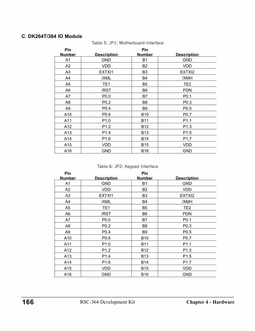
C. DK264T/364 IO ModuleTable 5: JP1: Motherboard Interface
Table 6: JP2: Keypad Interface
PinNumber Description
PinNumber Description
A1 GND B1 GNDA2 VDD B2 VDDA3 EXTXI1 B3 EXTXI2A4 /XML B4 /XMHA5 TE1 B5 TE2A6 /RST B6 PDNA7 P0.0 B7 P0.1A8 P0.2 B8 P0.3A9 P0.4 B9 P0.5A10 P0.6 B10 P0.7A11 P1.0 B11 P1.1A12 P1.2 B12 P1.3A13 P1.4 B13 P1.5A14 P1.6 B14 P1.7A15 VDD B15 VDDA16 GND B16 GND
PinNumber Description
PinNumber Description
A1 GND B1 GNDA2 VDD B2 VDDA3 EXTXI1 B3 EXTXI2A4 /XML B4 /XMHA5 TE1 B5 TE2A6 /RST B6 PDNA7 P0.0 B7 P0.1A8 P0.2 B8 P0.3A9 P0.4 B9 P0.5A10 P0.6 B10 P0.7A11 P1.0 B11 P1.1A12 P1.2 B12 P1.3A13 P1.4 B13 P1.5A14 P1.6 B14 P1.7A15 VDD B15 VDDA16 GND B16 GND
166 RSC-364 Development Kit Chapter 4 - Hardware
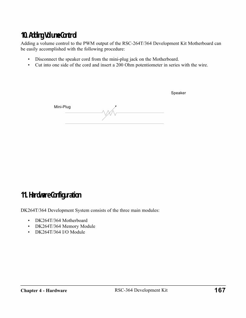
10. Adding Volume ControlAdding a volume control to the PWM output of the RSC-264T/364 Development Kit Motherboard canbe easily accomplished with the following procedure:
• Disconnect the speaker cord from the mini-plug jack on the Motherboard.• Cut into one side of the cord and insert a 200 Ohm potentiometer in series with the wire.
11. Hardware Configuration
DK264T/364 Development System consists of the three main modules:
• DK264T/364 Motherboard• DK264T/364 Memory Module• DK264T/364 I/O Module
Mini-Plug
Speaker
167RSC-364 Development KitChapter 4 - Hardware

A. DK264T/364 Motherboard
• Power SupplyThere are three settings for the power supply voltage.
5VInput: 5.3 ~ 9VDC (regulated or unregulated power supply)Select 5V for the on-board voltage regulator
Adjustable (2.7V ~ 5V)Input: 3.0 ~ 5.3VDC (regulated power supply)Select 5V for the on-board voltage regulator
3VInput: 3.3 ~ 9V DC (regulated or unregulated power supply)Select 3V for the on-board voltage regulator
• To select 5V, place the shorting block on "5V" at JB1 • To select 3V, place the shorting block on "3V" at JB1
CAUTION: Ensure that the memory IC's added to the Memory Module are rated at the correct voltage.
Oscillator-1 and Oscillator-2There are two different modes of operation for Oscillator-1 and two for Oscillator-2 as shown in thetable below.
DK264T/364I/O Module
DK264T/364Motherboard
DK264T/364Memory Module
168 RSC-364 Development Kit Chapter 4 - Hardware

External Clock Inputs On-board Oscillators (Crystal)
Oscillator-1• The Motherboard is shipped with the 14.318MHz crystal installed.• To use an external clock instead of the preinstalled crystal, remove C21 and Y1
(a) To connect an external oscillator to the Motherboard:• Solder a jumper wire from the clock circuit's output to the XI1 through-hole located below R15.• Solder a jumper wire from the clock circuit's ground to the GND though-hole located below XI1.
(b) To bring in a clock signal built on the I/O module, solder a jumper wire from the XI1through-hole located below R15 to the XI1 through-hole located near R22.
Oscillator-2• The Motherboard is shipped without crystal Y2 installed.• To use the on-board oscillator, install Y2, C19 (68pF). C18 can be omitted.• To use the external clock.
(a) To connect an external oscillator to the Motherboard:• Solder a jumper wire from the clock circuit's output to the XI2 through-hole located below R28.• Solder a jumper wire from the clock circuit's ground to the GND though-hole located below XI2.
(b) To bring in a clock signal built on the I/O module, solder a jumper wire from the XI2through-hole located below R28 to the XI2 through-hole located near R22.
DAC Output The un-buffered DAC output (before LM4862) can be tapped at J5.
To tap the DAC output after the filter, place the shorting blocks at FILTERED on JB-2 and JB-3.
To tap the DAC output directly from the RSC chip, place the shorting blocks at DIRECT on JB-2 and
External Clock Inputs On-board Oscillators (Crystal)
Oscillator-1 Yes (14.318MHz) Yes (14.318MHz)
Oscillator-2 Yes Yes (Note: Oscillator-2 components are not populatedon the board.)
169RSC-364 Development KitChapter 4 - Hardware

JB-3.
Note: When DIRECT is selected, there will be no sound at the amplified DAC output at J3 (labeledSPEAKER OUT).
SW-A, SW-B, and SW-C Push ButtonsThe connections for the SW-A, SW-B, and SW-C push buttons have to be made in the wiring area onthe motherboard. Each switch can be connected to any of GPIO (P0.0 ~ P1.7) by connecting wires fromJP4 to JP3 and JP4 to JP5. In some revisions, SW-A, SW-B, and SW-C at JP4 are labeled as '1', '2', and'3' respectively.
LEDs and DIP SwitchesTo make connections from GPIO to LEDs, place the DIP switches in the ON positions.
For example, to connect P0.0 output to the P0.0 LED, set the right-most DIP switch setting of S2 to theON position.
Note: Although all GPIO ports are buffered with 74HC240s to drive the LEDs, when the connections are made with the DIP switch set-tings, the ports are pulled up to Vdd with 100K resistors.
RS232 InterfaceThere are three configuration settings for the RS232 Interface.
To enable the RS232 Interface IC (U3) all the time:
Disconnect Connect JB4 X JB5 X JB6 X
JB7 X
P1.7-RS232EN Manual-RS232EN
170 RSC-364 Development Kit Chapter 4 - Hardware

To control the RS232 Interface IC (U3) by software:Note: P1.7 will be used to disable or enable U3.
To disable the RS232 Interface IC (U3) all the time:
B. DK264T/364 Memory Module
Memory TypesThere are 7 memory ICs in Memory Module board as shown in the table below.
DIP Accepts 28 and 32 pin. 512Kbit to 4Mbit.Note: The DIP socket is useful for an EPROM emulator.
PLCC-A Accepts 32 pin. 512Kbit to 4Mbit.PLCC-B Accepts 32 pin. 512Kbit to 4Mbit.TSOP-A Foot-print for the 32 pin memory IC for TSOP (Unpopulated)TSOP-B M29W400T, 4MbitSRAM-A TC55257DFTL, 32KbitSerial EEPROM 24C65, 64Kbit
Disconnect Connect JB4 X JB5 X JB6 X
JB7 X
P1.7-RS232EN Manual-RS232EN
Disconnect Connect JB4 X JB5 X JB6 X
JB7 X
P1.7-RS232EN Manual-RS232EN
171RSC-364 Development KitChapter 4 - Hardware
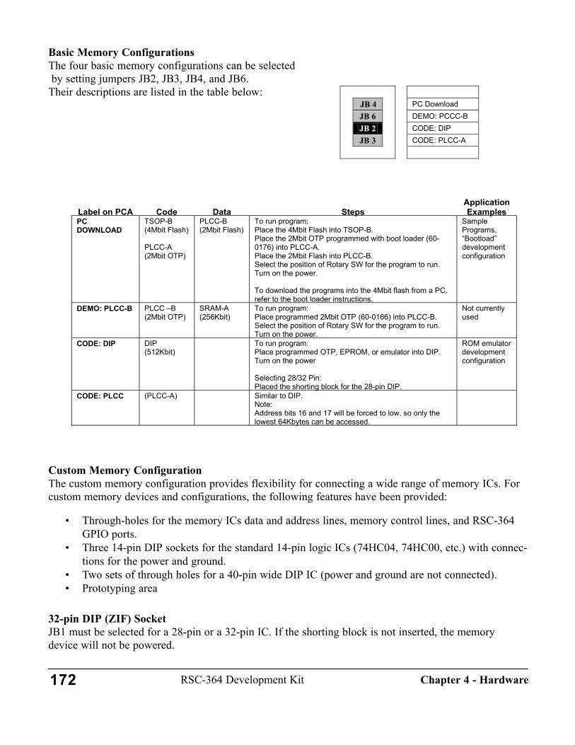
Basic Memory ConfigurationsThe four basic memory configurations can be selectedby setting jumpers JB2, JB3, JB4, and JB6.
Their descriptions are listed in the table below:
Custom Memory ConfigurationThe custom memory configuration provides flexibility for connecting a wide range of memory ICs. Forcustom memory devices and configurations, the following features have been provided:
• Through-holes for the memory ICs data and address lines, memory control lines, and RSC-364GPIO ports.
• Three 14-pin DIP sockets for the standard 14-pin logic ICs (74HC04, 74HC00, etc.) with connec-tions for the power and ground.
• Two sets of through holes for a 40-pin wide DIP IC (power and ground are not connected).• Prototyping area
32-pin DIP (ZIF) SocketJB1 must be selected for a 28-pin or a 32-pin IC. If the shorting block is not inserted, the memorydevice will not be powered.
Label on PCA Code Data StepsApplicationExamples
PCDOWNLOAD
TSOP-B(4Mbit Flash)
PLCC-A(2Mbit OTP)
PLCC-B(2Mbit Flash)
To run program:Place the 4Mbit Flash into TSOP-B.Place the 2Mbit OTP programmed with boot loader (60-0176) into PLCC-A.Place the 2Mbit Flash into PLCC-B.Select the position of Rotary SW for the program to run.Turn on the power.
To download the programs into the 4Mbit flash from a PC,refer to the boot loader instructions.
SamplePrograms,“Bootload”developmentconfiguration
DEMO: PLCC-B PLCC –B(2Mbit OTP)
SRAM-A(256Kbit)
To run program:Place programmed 2Mbit OTP (60-0166) into PLCC-B.Select the position of Rotary SW for the program to run.Turn on the power.
Not currentlyused
CODE: DIP DIP(512Kbit)
To run program:Place programmed OTP, EPROM, or emulator into DIP.Turn on the power
Selecting 28/32 Pin:Placed the shorting block for the 28-pin DIP.
ROM emulatordevelopmentconfiguration
CODE: PLCC (PLCC-A) Similar to DIP.Note:Address bits 16 and 17 will be forced to low, so only thelowest 64Kbytes can be accessed.
JB 4 PC Download JB 6 DEMO: PCCC-B JB 2 CODE: DIP JB 3 CODE: PLCC-A
172 RSC-364 Development Kit Chapter 4 - Hardware
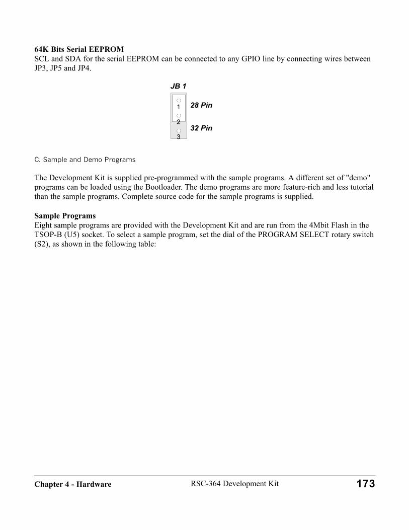
64K Bits Serial EEPROMSCL and SDA for the serial EEPROM can be connected to any GPIO line by connecting wires betweenJP3, JP5 and JP4.
C. Sample and Demo Programs
The Development Kit is supplied pre-programmed with the sample programs. A different set of "demo"programs can be loaded using the Bootloader. The demo programs are more feature-rich and less tutorialthan the sample programs. Complete source code for the sample programs is supplied.
Sample ProgramsEight sample programs are provided with the Development Kit and are run from the 4Mbit Flash in theTSOP-B (U5) socket. To select a sample program, set the dial of the PROGRAM SELECT rotary switch(S2), as shown in the following table:
173RSC-364 Development KitChapter 4 - Hardware
JB 1
28 Pin
32 Pin
1
3
2

Demo ProgramsEight demo programs are provided with the Development Kit. These files can be loaded and run fromthe 4Mbit Flash in the TSOP-B (U5) socket. See separate descriptions of these programs.
12. Installing and Removing the Sample FlashSome configurations require installing or removing the Sample Flash in location TSOP-B. This opera-tion must be done with care, as the leads of the TSOP package are delicate. Follow the proceduredescribed below to install the part.
1. Work at an ESD-safe workstation. Memory devices are especially susceptible to ESD.2. Make sure the power is turned off before inserting any new IC into the Development Kit.3. Place the flash memory (which is either a Toshiba TC58F400T/B or an SGS-Thompson
M29W400T) into the TSOP-B socket with pin 1 closest to C5. The plastic portion of the socketcontains a well that receives the body of the IC, and the leads rest on top of the socket pins.When installed correctly, the chip will rest snugly in the well and the text on the chip will beupside-down compared with the text silk-screened on the developer kit Memory Module.
4. Note that the small aluminum door is shaped somewhat like a sled, with one pair of smooth tabsand one pair of serrated tabs. When properly installed, all four tabs will be captured by slots in
RotarySwitch Demo Program Description Address
Start: 000007 Music Three song music sample.
End: 0FFFFStart: 10000
6 Password Speaker Verification, words-on-chip, Sleep with IO wakeup End: 1FFFF
Start: 200005 Record and Play Voice record and playback demo
with 2-bit and 3-bit compression. End: 2FFFFStart: 30000
4 Wordspot Speaker Dependent recognitionof words within fluent speech End: 3FFFF
Start: 400003 Fast Digits
Telephonic fast digitsdemonstration using DualRecognition and SpeakerAdaptive Technology.
End: 4FFFF
Start: 500002 Speaker-Verification
Speaker verification recognitionusing queuing for one to fourwords. End: 5FFFF
Start: 600001 Speaker-Dependent
Up to 32-word speakerdependent recognition withsimultaneous pattern generationand nametag recording.
End: 6FFFF
0 Speaker-Independent
Speaker independent demofeaturing the SI6 and Yes/Noweightsets.
Start: 70000
174 RSC-364 Development Kit Chapter 4 - Hardware
the socket. The edge of the door near the serrated tabs has a small notch.5. Insert the serrated tabs into the slots on the socket and flip the door down to cover the Sample
Flash, taking care not to disturb the position of the IC.6. While pressing down firmly on the sides of the door near the smooth tabs, slide the door closed.
It may help to use a small screwdriver to push against the notch or the square in the middle ofthe door while you press down on the sides to close it. Note that the small tabs in the aluminumdoor will slide through slots in the socket and the door will "click" into place.
7. Install jumper block JB1:BOOT_LOAD. Other jumpers may also be installed, depending on theconfiguration.CAUTION: make sure the Sample Flash voltage rating (3V or 5V) is the same as the voltage set-ting of the board before applying power.
To remove the Sample Flash, follow the safety steps above and reverse the procedure. To release thedoor, insert a small screwdriver vertically between the aluminum door and the socket body and lever thedoor towards the serrated tabs until the smooth tabs are free.
175RSC-364 Development KitChapter 4 - Hardware

176
CHAPTER 5 - SIMULATOR
This chapter provides a description of the simulator software and user inter-face for the RSC-264T and the RSC-364. The simulator is a software onlyprogram that allows a personal computer to run a simulation of the RSC-264T/364 processor. Although some internal details of these two chips differsignificantly, the portions simulated in software are similar, so this descrip-tion applies to both chips. No external hardware (other than a PC) isrequired to operate the simulator. The chapter begins with a description ofhow to start the simulator and then proceeds with a description of the vari-ous user interface windows. This chapter also contains a simulator tutorial,which will familiarize the user with the simulator functions.

1. Introduction This is a description of the simulator in the RSC-264T/364 Development Kit. It assumes the reader isfamiliar with the architecture of the RSC-264T/364 chip, and has the appropriate Data Book availablefor detailed descriptions of the chip's features and functions.
The simulator is a software executable program that allows an IBM compatible personal computer tooperate on RSC-264T/364 binary code to perform a software simulation of the RSC-264T/364 processor.The simulator does not support simulation of the specialized on-chip hardware needed for speech syn-thesis or speech recognition. Therefore, the simulator cannot be used to check these sections of code ina program. No external hardware is required to run in simulator mode.
User Equipment RequirementsThe simulator requires an IBM compatible PC running Windows 3.1 or version 3.11 (Windows forWorkgroups), Windows 95, or Windows 98.
Software DescriptionThe simulator program resides in a single executable called simulate.exe.
2. Starting the SimulatorTo start the simulator, run the simulate.exe program (located in the \BIN directory). The display windowcontains a Menu bar, a dialog box called Control Window and a Source Code List window that showsthe current code space (see Figure 1). The figure also shows two optional windows, Display SFR RAMand Scratchpad RAM. These are described below. The actual display may be different depending onscreen resolution, video card and driver, and the Windows operating system version.
177RSC-364 Development KitChapter 5 - Simulator
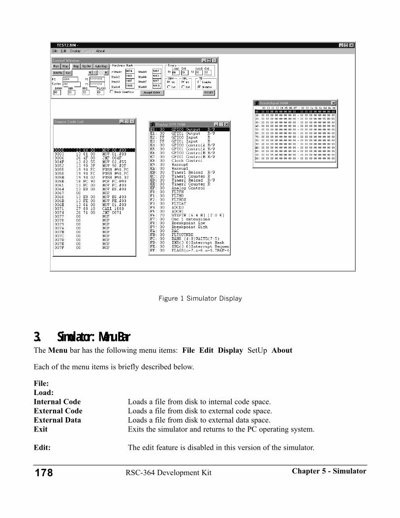
Figure 1 Simulator Display
3. Simulator: Menu BarThe Menu bar has the following menu items: File Edit Display SetUp About
Each of the menu items is briefly described below.
File:Load:Internal Code Loads a file from disk to internal code space.External Code Loads a file from disk to external code space.External Data Loads a file from disk to external data space.Exit Exits the simulator and returns to the PC operating system.
Edit: The edit feature is disabled in this version of the simulator.
178 RSC-364 Development Kit Chapter 5 - Simulator

Display:All Bank RAM Loads and displays a window showing RAM contents 100h-1FFh (Banks
8-F).SFR RAM Loads and displays a window showing RAM contents E0h-FFh. These
"Special Function Registers" are not actually RAM locations, but they mapto RAM addresses.
ScratchPad RAM* Loads and displays a window showing RAM contents 0h-DFh. The data from C0h-DFh show the contents of the currently selected bank.
Internal CODE Space Loads and displays a window showing internal code space.External CODE Space Loads and displays a window showing external code space.External DATA Space Loads and displays a window showing external data space.
* The ScratchPad RAM is the on-chip RAM referenced in the Data Book as Register Space.
Note: The Display menu items are explained in more detail in the Using the Display Menu subsectionthat follows. This subsection also describes the editing options available for several of the menu items.
SetUp: This menu item is disabled in the current version.
About:Names This brings up a box showing the Sensory, Inc. copyright notice,
programmers' credits and the software version.
Using the Display MenuThis section provides more information on how to display register (on-chip RAM) and code contentsand edit register contents for the appropriate menu items shown below.
Display:All Bank RAMThe All Bank RAM section of the on-chip RAM is divided into 32-byte banks which are referred to asBank8 through BankF (see Figure 2). This menu item loads and displays a window showing the on-chipRAM contents 100h-1FFh (see Figure 2). If necessary, re-size the window to display the bank of inter-est. Double clicking on a line of register contents brings up an edit dialog box that allows the contents ofthe registers to be modified.
179RSC-364 Development KitChapter 5 - Simulator
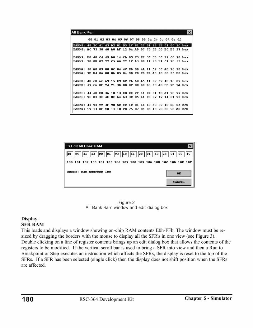
Figure 2 All Bank Ram window and edit dialog box
Display:SFR RAMThis loads and displays a window showing on-chip RAM contents E0h-FFh. The window must be re-sized by dragging the borders with the mouse to display all the SFR's in one view (see Figure 3).Double clicking on a line of register contents brings up an edit dialog box that allows the contents of theregisters to be modified. If the vertical scroll bar is used to bring a SFR into view and then a Run toBreakpoint or Step executes an instruction which affects the SFRs, the display is reset to the top of theSFRs. If a SFR has been selected (single click) then the display does not shift position when the SFRsare affected.
180 RSC-364 Development Kit Chapter 5 - Simulator
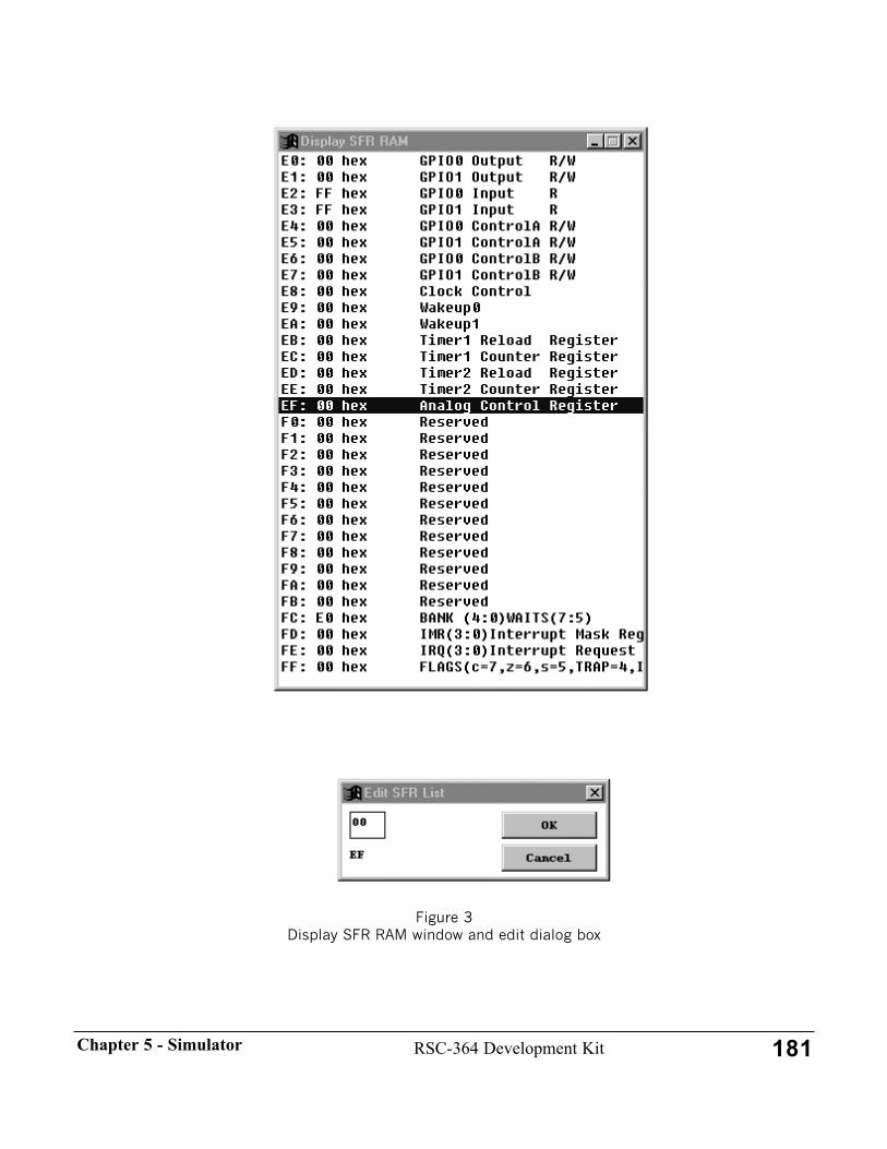
Figure 3 Display SFR RAM window and edit dialog box
181RSC-364 Development KitChapter 5 - Simulator

Display:ScratchPad RAMThis loads and displays a window showing on-chip RAM contents 0h-DFh (see Figure 4). Double click-ing on a line of register contents brings up an edit dialog box that allows the contents of the registers tobe modified.
Figure 4Scratch Pad RAM window and edit dialog box
Internal CODE Space, External CODE Space, and External DATA SpaceThe code and data space windows all operate in essentially the same manner. They each initially displaya section of code or data space beginning at address 0000h (see Figure 5). The 64K code or data space isdivided into 32 blocks for display; each block is 2048 bytes in length. The window size can be increased
182 RSC-364 Development Kit Chapter 5 - Simulator
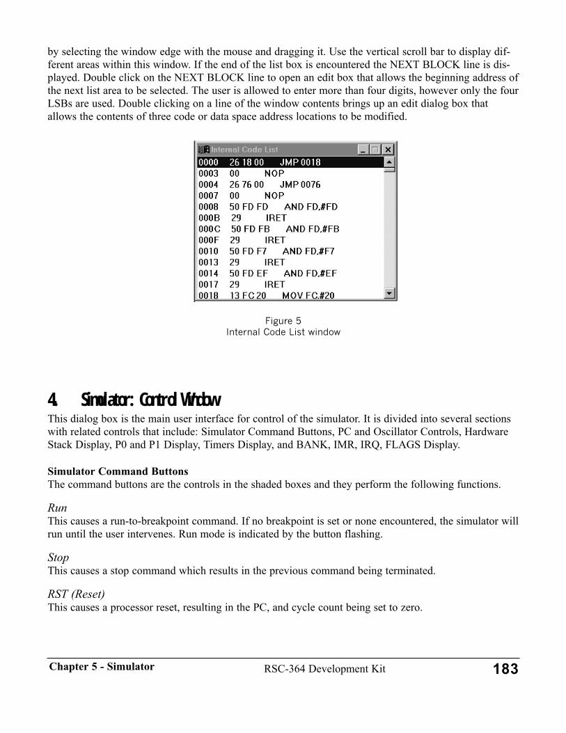
by selecting the window edge with the mouse and dragging it. Use the vertical scroll bar to display dif-ferent areas within this window. If the end of the list box is encountered the NEXT BLOCK line is dis-played. Double click on the NEXT BLOCK line to open an edit box that allows the beginning address ofthe next list area to be selected. The user is allowed to enter more than four digits, however only the fourLSBs are used. Double clicking on a line of the window contents brings up an edit dialog box thatallows the contents of three code or data space address locations to be modified.
Figure 5Internal Code List window
4. Simulator: Control WindowThis dialog box is the main user interface for control of the simulator. It is divided into several sectionswith related controls that include: Simulator Command Buttons, PC and Oscillator Controls, HardwareStack Display, P0 and P1 Display, Timers Display, and BANK, IMR, IRQ, FLAGS Display.
Simulator Command ButtonsThe command buttons are the controls in the shaded boxes and they perform the following functions.
RunThis causes a run-to-breakpoint command. If no breakpoint is set or none encountered, the simulator willrun until the user intervenes. Run mode is indicated by the button flashing.
StopThis causes a stop command which results in the previous command being terminated.
RST (Reset)This causes a processor reset, resulting in the PC, and cycle count being set to zero.
183RSC-364 Development KitChapter 5 - Simulator

StepThis causes a single step to be executed. Note that the Source Code List window displays the step histo-ry.
StpOvr (StepOver)This causes a run to the next return instruction (RET) up to the current level of subroutines to be execut-ed.
Example: Executing the following code from address 0000h by using the StpOvr button willresult in the simulator stopping at address 0004h.
0000 00 nop0001 27 CALL 000A ;calls a subroutine at address 000Ah0004 00 nop ;returns to here and stops simulation0005 00 nop 0006 00 nop 0007 00 nop 0008 00 nop 0009 00 nop 000A 00 nop ;subroutine starts here000B 28 RET ;and returns from here to address 0004h000C 00 nop
AutoStep and Slider ControlThese two controls allow multiple single step operations to be executed. The Slider controls the speed atwhich the steps are executed. Autostep stops if a breakpoint is reached.
BrkPts (Breakpoints)This button brings up a dialog box that allows up to four breakpoints to be set. It is initialized to onebreakpoint at 0000h so that processing stops at the beginning address to indicate a software restart orwrap-around from address FFFFh. The dialog box commands are shown in Figure 6.
The components of this dialog box are: four breakpoint boxes that allow the user to enter four hex digitsfor each breakpoint, an OK button that closes the dialog box after entries have been made, and a Cancelbutton which closes the dialog box.
184 RSC-364 Development Kit Chapter 5 - Simulator

Figure 6 Breakpoints List Simulator Mode Dialog Box Controls
OscThis button is described in the PC and Oscillator Controls section (see following page).
Accept EditsThis button acts as the default button to accept edits in the edits fields.
Simulator Mode Controls (radio buttons)The mode controls consist of the XML and XMH radio buttons and the TE Enable and Disable radiobuttons.
The two XML and two XMH radio buttons control the code space from which the simulator is retriev-ing instructions on which to operate. The code space can be defined in 32K blocks as Low or Highpages of the 64K code space in Internal or External code space. The two XML buttons and the twoXMH buttons are mutually exclusive. For example, if the XML Int button is enabled and XMH Extbutton is enabled, the simulator will operate on code in the Internal space from 0000h to 7FFFH and oncode from External space from 8000h to FFFFh.
The TE (Test Enable) radio buttons determine whether or not the TEST jump vector gets executedwhen a Reset occurs. If the TE Enable button is selected, the processor will vector to FFFCh (the TESTjump vector) when a Reset occurs. If the TE Disable button is selected, the processor will go to 0000hwhen a Reset occurs.
PC and Oscillator Controls (edit windows)These controls consist of the PC (program counter) edit box, Cycles (cycle count) edit box and the Osc(set oscillators) button that brings up a dialog box that allows the oscillator values to be set.
The PC edit box takes a hexadecimal value and loads it to the simulator program counter. The updateoccurs when the input focus leaves the edit box via the Accept Edits button, the keyboard Enter key, thekeyboard Tab key, or selecting a different window with the mouse. The Source Code List window isupdated to show the code at the new address.
The Cycles edit box takes a decimal value and loads it to the simulator cycle count location. This allowsthe cycle count to be initialized to a desired starting value.
185RSC-364 Development KitChapter 5 - Simulator

The Osc button opens a dialog box that allows the user to set values for oscillator 1 and oscillator 2. Theratio of these values is used to determine the timer count (see Timers Display on next page) of the oscil-lator and are NOT used as the processor clock source. These values have no effect on Cycle Count orthe timer count of the processor clock source. Therefore, the processor source driven timer will alwaysshow the same result for a given instruction. The default values are 14318100 (symbolizing14.3181MHz) for Oscillator 1 and 32768 for Oscillator 2.
Hardware Stack DisplayThe Hardware Stack display consists of eight edit boxes that display the contents of the eight hardwarestack locations. An arrow points to one of these locations to indicate that this is the next location to bewritten into when a CALL instruction is encountered. There is also a Stack Overflow radio button,which simulates operation of the corresponding bit in the flags register. The Stack Overflow radio buttonis set when the last stack location has been written. This is an early warning that the stack is full and thatoverflow will occur if another call is made or interrupt happens.
P0 and P1 Display (Output Ports)The P0 and P1 displays indicate the status of the pins in port0 and port1 as they are seen at the inputports. This is because in the RSC-264T/364, the output port is wrapped into the input port.
Register address E2h: GPIO0 Input Register (P0IN as referenced in Data Book)Register address E3h: GPIO1 Input Register (P1IN as referenced in Data Book)
The configuration of the I/O ports as inputs or outputs is defined by the SFR registers at the followinglocations.
Port0:Register address E4h: GPIO0 Control A (P0CTLA as referenced in Data Book)Register address E6h: GPIO0 Control B (P0CTLB as referenced in Data Book)
Port1:Register address E5h: GPIO1 Control A (P1CTLA as referenced in Data Book)Register address E7h: GPIO1 Control B (P1CTLB as referenced in Data Book)
The value of the output port is defined in the SFR registers at the following locations:
Port0:Register address E0h: GPIO0 Output (P0OUT as referenced in Data Book)
Port1:Register address E1h: GPIO1 Output (P1OUT as referenced in Data Book)
Example: If the GPIO0 Control A and Control B register contain 0Fh, then the bits 0-3 are configuredas outputs and the bits 4-7 are configured as Input-Weak pull-up. If the GPIO0 Output register containsCCh then the P0 display for port0 contains the value 11111100 binary. Bits 0-3 are outputs with thevalue Ch and bits 4-7 are weak pull-up inputs.
186 RSC-364 Development Kit Chapter 5 - Simulator

Timers DisplayTimer values are calculated for each operation executed based on the number of processor cycles it takesto perform the operation (including wait states), the timer pre-scalers, and the ratio of the two oscillatorfrequency values.
There are two edit boxes for T1 (Timer1) and two edit boxes for T2 (Timer2). The Load boxes displaythe contents of the Timer1 and Timer2 Reload Registers of the Special Function Registers (SFRs). TheCnt boxes display the contents of the Timer1 and Timer2 Counter Registers of the SFRs. The registersare summarized below.
Register address EBh: Timer1 Reload Register.This is the value reloaded to the counter registe when it overflows. (T1R in Data Book)
Register address ECh: Timer1 Counter RegisterThis is the timer counter value. It is a read-only register, writes to this register cause the reload registervalue to be loaded. (T1V in Data Book)
Register address EDh: Timer2 Reload RegisterThis is the value reloaded to the counter register when it overflows. (T2R in Data Book)
Register address EEh: Timer2 Counter Register This is the timer counter value. It is a read-only register, writes to this register cause the reload registervalue to be loaded. (T2V in Data Book)
BANK, IMR, IRQ, FLAGS Display (SFR: Special Function Register)This section of the Control Window displays four frequently monitored SFR registers in edit boxes. Thefour registers are summarized below.
Register address FCh: BANK RAM bank select (bits0-4) and Wait States (bits 5-7) Register address FDh: IMR Interrupt Mask Register bits.Register address FEh: IRQ Interrupt Request Register bits.Register address FFh: FLAGSFlags Register bits.
5. Simulator: Source Code ListThis window shows the code in three sections, which reflect the stages of code execution. The "history"section shows the code that has been processed and is shown above the highlighted line. The singlehighlighted line represents the current code pointed to by the program counter. The "look-ahead" sectionshows the code that will be processed and is shown below the highlighted line. When the RST (Reset)button is pressed, the "history" section is blanked to indicate that no code has been processed.
6. Simulator TutorialThis section is a tutorial to familiarize the Simulator user with the following functions:
187RSC-364 Development KitChapter 5 - Simulator

• Loading Files.• Switching between different code spaces and the use of the XML and XMH controls.• Displaying code space.• The Run, Stop, RST, Step, StpOvr, AutoStep, and Brkpts buttons.• Displaying and editing registers.• Editing code space.• Editing the Control Window edit boxes.• Exiting the Simulator.
Tutorial Steps1. Load the file called tutorial.bin into external code space by using the File: Load: External Code
menu bar selections. The file is located in the \SAMPLES\TUTORIAL directory of suppliedfloppy disk or on the user's hard drive.
2. Set the XML radio buttons to Ext (External). Select the RST button (Reset) to load the currentcode into the Source Code List window.
3. Use the Step button to single step to address 8000h. The Source Code List window shows whathappens when the processor transitions across the 32K high and low address space. The historyshows code that has executed in the low part of external space and the current line shows thecode that is about to execute in the high part of internal space. Note that no code is loaded hereand that it is all " 00 NOP " instructions.
4. Set the XMH radio buttons to Ext and reset the Simulator by selecting the RST button. Use theStep button to single step to address 8000h and note that the list now shows executable code inthe high part of external code space.
5. Use the Display menu bar item to display the External CODE Space. Use the vertical scroll bar tomove to the NEXT BLOCK line at the end of the code list. Double click on the NEXT BLOCKline and use the edit box to set the beginning of the list at 8000h. Check that the External CodeList displays the same code as in the Source Code List window.
6. Step through the code to demonstrate how the Source Code List displays the code space. Note theCALL and RET instructions.
7. AutoStep through the code and use the AutoStep Slider control to set the execution rate. Use theStep and Stop buttons to end the AutoStep command.
8. Use the Run command button to run through the code. Note that the Run button is flashing andthat none of the displays are being updated. Use the Stop button to stop the Run command. Notethat the displays are updated to where the Simulator stopped running.
9. Step to address 8000h. Use the StpOvr button to run to the instruction after the RET instruction ataddress 802Ch. Set a breakpoint at 8000h by using the BrkPts button. Run to this breakpoint.
188 RSC-364 Development Kit Chapter 5 - Simulator
AutoStep to this breakpoint. Remove the breakpoint and Run again. The Simulator is now run-ning and no displays are being updated. Stop the Simulator.
10. Use the Display menu bar item to display the ScratchPad RAM registers. AutoStep through thecode and note that register 0 displays the values being written to it. Stop the Simulator and editregister 0 by double clicking on the line that contains register 0. Insert a new value then Step theSimulator to display the edited value being overwritten by the executed instructions.
11. Edit the External Code List window by double clicking on address location 8024h. Change thecode at location 8026h from 80 to 81. Observe the new instruction in the list windows. Thisforces a jump to a new section of code.
12. Step through the new section of code up to memory location 8101h. At address 8101h, edit theFLAGS register in the Control Window to load the value 00h. This will clear the Carry bit andcause the JNC instruction to jump to address 8100h upon the next Step command. Step up tomemory location 8105h. At address 8105h edit the FLAGS register in the Control Window toload the value 80h. This sets the Carry bit and the JNC instruction at 8105h will not jump. Thecode "falls through" to address 8108h, which is an error since no code is loaded here. Edit the PCin the Control Window to set the Simulator to address 8100h and hit the computer Enter key toinsert this value into the PC.Use the Step button to demonstrate that the Simulator continues step-ping from this new location.
13. Exit the Simulator by choosing the File: Exit menu bar selections or use the icon in the top leftof the screen to close the window. This completes the Simulator tutorial.
7. Simulator Operation NotesThis section contains information on known problems with the simulator software operation. The usershould carefully read each of the notes below to be aware of the problems, and to know what to do whenthey are encountered during simulator operation.
1. The External Data List window may open up in a different size after being opened three or moretimes during a session. The user will have to resize as desired.
1. 1. 2. When using Windows 3.1: the Internal Code List, External Code List, or External Data Listwindows will be displayed in the "Home" corner, reduced to their minimum dimensions, eachtime they are opened after the first time of being opened and closed. The user will have to movethe window and enlarge as desired.
3. The Internal Code List, External Code List, External Data List, Source Code List, and the SFRRAM windows can not be moved on top of the Control Window, All Bank RAM window, orScratchPad RAM window.
4. When in an Edit SFR List window, if the Cancel button is clicked, an "Error During Edit" mes-sage occurs. The error window can be cleared and the system continues to function.
5. The selection of the RST command button does not cause the program counter and cycle countboxes to display zero. The boxes do display the proper information after the next Step commandis selected.
189RSC-364 Development KitChapter 5 - Simulator

190 RSC-364 Development Kit Chapter 5 - Simulator
191
CHAPTER 6 - ASSEMBLER & LINKERThis chapter contains reference information on the Sensory RSC-264T/364 assembler,SASM2.EXE, and linker programs. The assembler subsection provides information oncommand line options, source code syntax, and descriptions of the various directives.The linker subsection provides a description of its command line options.
Applications that use speech synthesis and/or speaker independent speech recognitionrequire the linking of speech data files and neural net weight tables with the other objectcode modules. The procedure for doing this is described in this section.
This chapter also contains a description of the RSC-264T/364 Assembler Extensionsrelated to the Intel 8051(tm), which may be useful to developers experienced with thatprocessor. A table lists the supported Intel 8051(tm) instructions, the corresponding RSC-264T/364 Assembler form of the instruction, and information on any source code modifi-cations required.
The Linker provided in this release is compatible with previous versions of SensoryDeveloper Kit releases. The Assembler, SASM2.EXE, is designed expressly for the newhardware architecture of the RSC-264T/364, and is NOT compatible with previous ver-sions.

1. General ReferenceEach of the programs (SASM2, CLINK) is normally started by typing a command at the MS-DOS com-mand prompt. The reference chapters for those programs describe the syntax and available options ofthese commands.
Each program returns an exit code of zero if there were no errors in processing. A non-zero exit codemay be used by a parent program or MS-DOS batch file to detect errors and stop processing.
Text File Input SyntaxEach line of input is terminated by an ASCII carriage return/line feed sequence. These lines of text arefurther subdivided into a sequence of source tokens. Tokens are groups of ASCII characters, separatedby blanks. There are five kinds of tokens recognized by SASM2:
Numeric constantsAlways start with a digit 0-9. A suffix letter following the number will determine the radix: "x" or "h"means hexadecimal, "o" or "q" means octal, "b" means binary. If none of these suffixes appears, thenumber is considered to be decimal. Hex constants may contain the letters [A-Fa-f], but must start with adigit --- FF00h is illegal, but 0FF00h is acceptable. Numeric constants are converted to a 32-bit integerform for internal use.
String LiteralsConsist of any ASCII text enclosed in quotation marks. String literals may be any length that fits on asingle line. Either single or double quotes may be used as the delimiter.
End Of LineIs either a carriage return, linefeed, or semicolon. The semicolon begins a comment so the text scannerignores the remainder of the line.
Symbolic NamesA group of characters generally resembling a word of English text. A symbol name must begin with analphabetic character (either upper or lower case) or the underbar character "_". Following the startingcharacter any combination of alphabetic characters, underbars, periods, and decimal digits may be used.Symbol names may be up to 19 characters in length.
Special CharactersAny nonblank characters that are not interpreted as one of the above tokens. These can be parentheses,punctuation, operator characters, etc. Each special character token contains a single character.
ExpressionsSASM2 expressions use the familiar algebraic infix notation. There are four major data types: numeric,address, external address, and character string. The operands and results of an expression may be any ofthese.
Numeric operands are specified either as literal constants or by using a symbolic name. Such a name
192RSC-364 Development KitChapter 6 - Assembler & Linker
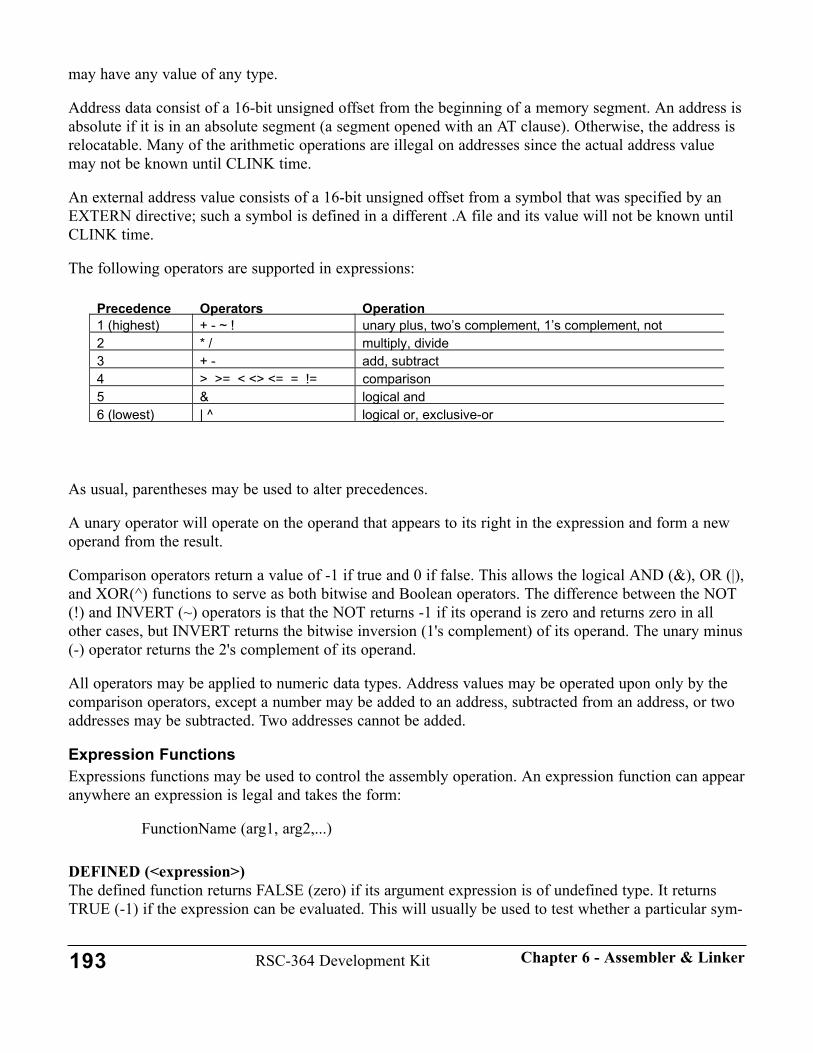
may have any value of any type.
Address data consist of a 16-bit unsigned offset from the beginning of a memory segment. An address isabsolute if it is in an absolute segment (a segment opened with an AT clause). Otherwise, the address isrelocatable. Many of the arithmetic operations are illegal on addresses since the actual address valuemay not be known until CLINK time.
An external address value consists of a 16-bit unsigned offset from a symbol that was specified by anEXTERN directive; such a symbol is defined in a different .A file and its value will not be known untilCLINK time.
The following operators are supported in expressions:
As usual, parentheses may be used to alter precedences.
A unary operator will operate on the operand that appears to its right in the expression and form a newoperand from the result.
Comparison operators return a value of -1 if true and 0 if false. This allows the logical AND (&), OR (|),and XOR(^) functions to serve as both bitwise and Boolean operators. The difference between the NOT(!) and INVERT (~) operators is that the NOT returns -1 if its operand is zero and returns zero in allother cases, but INVERT returns the bitwise inversion (1's complement) of its operand. The unary minus(-) operator returns the 2's complement of its operand.
All operators may be applied to numeric data types. Address values may be operated upon only by thecomparison operators, except a number may be added to an address, subtracted from an address, or twoaddresses may be subtracted. Two addresses cannot be added.
Expression FunctionsExpressions functions may be used to control the assembly operation. An expression function can appearanywhere an expression is legal and takes the form:
FunctionName (arg1, arg2,...)
DEFINED (<expression>)The defined function returns FALSE (zero) if its argument expression is of undefined type. It returnsTRUE (-1) if the expression can be evaluated. This will usually be used to test whether a particular sym-
Precedence Operators Operation1 (highest) + - ~ ! unary plus, two’s complement, 1’s complement, not2 * / multiply, divide3 + - add, subtract4 > >= < <> <= = != comparison5 & logical and6 (lowest) | ^ logical or, exclusive-or
193 RSC-364 Development Kit Chapter 6 - Assembler & Linker

bol has been defined.
If the expression contains a forward reference, DEFINED will return FALSE during pass1 and TRUEduring pass 2 of SASM2.
OFFSET (<expression>)The offset function takes an address expression and returns a number. The result is the distance of theargument expression from the beginning of the segment in which it resides. External addresses are notlegal.
MOD (<number>,<number>)The mod function is the standard modulus function. Mod(a,b) returns the remainder from the integerdivision a/b.
SHL (<number>,<shift-count>) or <number> SHL <shift-count>SHR (<number>,<shift-count>) or <number> SHR <shift-count>
SHL and SHR are shift-left and shift-right functions. The shift count must be a number in the range[0..31]. The value returned is the first argument shifted by the number of bits given in the second argu-ment. SHR performs an arithmetic right-shift - that is, the original sign bit is retained through the opera-tion.
LOW (<expression>)HIGH (<expression>)LOW and HIGH are byte-extraction functions. The expression must evaluate to a numeric value in therange [-32768..65535]. The value returned is either the low 8-bits or the high 8-bits of the argument.NOTE: LOW and HIGH may be used only in the context of an instruction opcode with immediateaddressing (e.g., mov a, #LOW (VALUE)).
2. Sensory Assembler (SASM2) ReferenceSASM2 is the assembler program that converts the assembly language programs (source code) into relo-catable machine language (object code) modules.
Command Line OptionsSASM2.EXE is the assembler program itself. It is started by a command of the following format:
SASM2 <source-name> <options>
The source name is a full path name acceptable to MS-DOS. If no source name is specified, SASM2will prompt for one. The default file type string ".A" will be appended to the name specified if no filetype was specified, and the resulting string used to open the source file. Therefore, if the specifiedsource-name is /SRC/MAIN, SASM2 will attempt to read file /SRC/MAIN.A. If the specified sourcefile does not exist, SASM2 will terminate with an error message. Only one source file may be specifiedfor each run of SASM2.
194RSC-364 Development KitChapter 6 - Assembler & Linker
While starting up, SASM2 looks for an MS-DOS environment variable by the name of CASMSPEC. Ifpresent, CASMSPEC contains command-line text used to set default options for SASM2 runs. Optionsin CASMSPEC have the same syntax as the command line options. Options actually specified in thecommand line always override CASMSPEC specifications.
Options each start with the "-" (minus) character, followed by a flag letter which selects the option.Options may be given in any order or omitted entirely. The flag letter may be followed (with no inter-vening blanks) by additional text relating to the option. Options are separated from each other and fromthe source name by blanks. All option text is case insensitive. The following options are legal:
-l-lNAMEThe -L option causes the assembler to generate a listing file. If -L is not present, no listing file will begenerated. NAME is optional -- if it is not present the source name will be used. NAMEmay be a full path name which is not in the current working directory. If no file type is given, the filetype string ".LST" will be appended to NAME (or the source name) and the resulting string used to openthe listing file for output. If the specified .LST file already exists it will be deleted and overwritten.
-tPATHThe -T option selects the drive or directory path name where SASM2 can create its temporary file. Ifthe -T option is not used, SASM2 will look for a shell environment variable named TMP and use itscontents instead. If variable TMP is also absent, the temporary file will be created in the current work-ing directory. SASM2's temporary file is named SASM.TMP and will be deleted before SASM2 termi-nates.
-oNAMEThe -O option selects the filename to be used for the object file output. If -O is used it must have aNAME specified. If the -O option is not given the source name will be used as NAME. NAME may bea full path name which is not in the current working directory. The file type string ".O" will be append-ed to NAME (or the source name) and the resulting string used to create the object file. If the specified.O file already exists it will be deleted and overwritten.
-dNAME-dNAME=TEXT-dNAME:TEXTThe -D option makes a symbol "NAME" available to SASM2 during assembly. NAME will be a char-acter string containing the string TEXT, or a string of length zero if no text was given. Colon and equalsign have identical meaning in this option; the colon must be used if you intend to use the -D optionwithin your CASMSPEC environment variable since the MS-DOS SET command will not allow anequal sign to appear in the environment string.
Overall Source SyntaxThe source file is processed as a sequence of lines. Each line is terminated by a carriage return/line feedsequence. While reading the source lines, SASM2 keeps count of the line number and includes thesenumbers in listings and error messages. Only one statement is allowed per line. Empty lines are accept-able and will be ignored by SASM2 but included in the line count.
195 RSC-364 Development Kit Chapter 6 - Assembler & Linker
Comments are denoted by the semicolon ";" character. Any text to the right of a semicolon will beignored by SASM2 but shown in the listing file. As far as SASM2, is concerned, a semicolon indicatesthe end of the line and further discussions of source line syntax will make that assumption. Therefore, aline starting with a semicolon is an empty line.
The first character position of each line is processed specially: if it contains a percent sign, " %", or anycharacter which is a legal starting character for a symbol name then the line will be considered to have alabel. If not, SASM2 will rule that no label is present for this statement. For most statements, the labelwill define a symbol which may be used in expressions elsewhere in the program. Typically (but notalways) the value of that symbol will be the current assembly address.
If a label is present, it may optionally be followed with a colon ":" character. The colon is never manda-tory and if present is always ignored. This is for compatibility with many different assemblers, some ofwhich require colons and some of which do not. If the colon is not present then a blank or tab charactershould be used to separate the label from any following text. A label may be alone on a line with notext, or with only a comment following it.
If no label is present but the line is not empty, the first character of the line should be a blank. Theremaining text on the line will be processed as an assembler statement. All statements which generatecode and/or allocate memory in the target processor are referred to as instructions. There are a numberof predefined statements which are used to control the operation of SASM2; these are referred to asSASM2 directives.
Following the label field, the source line is interpreted as a sequence of tokens, which may be separatedby blanks. The blanks are not required unless the tokens could not otherwise be distinguished. Multipleblanks may be used anywhere that a single blank character is legal, and SASM2 will ignore the extrablanks.
DirectivesSASM2 directives are all of the same general form: the first token (after the label, if any) is an identifierword which determines the type of directive. The nature of the text to the right of this directive namewill depend on the particular directive involved. This additional text is referred to as arguments to thedirective. These directives are defined by SASM2 itself and their operation cannot be altered.
The INCLUDE DirectiveExample:
INCLUDE "..\INCLUDE\FILE.INC"
The INCLUDE directive allows no label. It takes one argument which must be a character stringexpression. The string will be used as a filename (full paths allowed) to open a file for input. No filetype will be appended to this filename, it will be used just as is. If there is no file by that name, SASM2will issue an error message and terminate. Source lines will be read from this file (an include file) untilthe end of file is reached. At that time the include file will be closed and the source file reopened tocontinue where it left off.When an INCLUDE directive opens an include file, the line number maintained by SASM2 starts overat line one and counts from there for the duration of the file. When the include ends, the correct line
196RSC-364 Development KitChapter 6 - Assembler & Linker
number for the source file is restored. Include file text appearing in SASM2 listing files show includefile line numbers with a "+" sign so that you know that the text you are seeing is not from the mainsource file. Error messages issued by SASM2 will also tell you the file name and the line number aswell to avoid confusion.
Include files can contain INCLUDE directives that include other files. They can be nested as deep asdesired.
The LIBINCL DirectiveThe LIBINCL directive is similar to the INCLUDE directive, except that is uses the DOS environmentvariable %LIBPATH% as the root of its file path. For example,
LIBINCL "\LIB364\MACROS\PATGEN.INC"
Will include the file contained at %libpath%\lib364\macropatgen.inc. The libpath can be a differentdirectory or drive. This directive allows switching libraries by simply changing the libpath variable, withno need to change the source file.
The END DirectiveThe END directive allows no label and no arguments. It marks the end of the source file. When SASM2encounters an END directive it stops reading source lines. The END directive is optional. If SASM2encounters the end of the source file it will automatically assume an END directive.
An END directive in an include file ends the include file but not the assembly. SASM2 returns to thesource file that issued the INCLUDE directive.
The SEGMENT DirectiveExample:
NAME SEGMENT "Mem.ROM" ALIGN(8) INPAGE(256)
The SEGMENT directive defines an address segment.
A SEGMENT directive normally has a label, which defines the name of the segment. CLINK will com-bine all segments bearing the same name into a single segment. If the label on a SEGMENT directiveduplicates one used on an earlier SEGMENT directive in the same source file, SASM2 reopens the pre-vious segment and adds the subsequent data onto that segment. When reopening a previous segment, noarguments are allowed on the SEGMENT directive.
If no label is specified, the segment is unnamed. SASM2 and CLINK will each invent names for internaluse in referring to unnamed segments, and these generated names will appear in listing and map files.
The SEGMENT directive accepts a list of option clauses separated by blanks. None of these options aremandatory -- a SEGMENT directive with no arguments is legal and useful. The following options areallowed:
"<class-name>"
197 RSC-364 Development Kit Chapter 6 - Assembler & Linker
The class-name clause appears as a quoted string constant. Complex string expressions are not allowed.Class names may contain any characters -- they are not constrained by the rules that control other identi-fiers. The class name defines the address class where this segment will be placed by CLINK. If noclass-name appears in a SEGMENT directive, the segment will be given a null class. The allowableclass names are "CODE", "REG", "DATA", "REGLIN", "REGOVERLAY", "REGSTACK","REGUSER". Most of these are for use by Sensory technology code - developers will have little needfor any other than "CODE".
AT <expression>The AT clause declares an absolute segment, starting at the address given. The expression must benumeric.
ALIGN <expression>The ALIGN clause tells the linker to place this segment starting at an address evenly divisible by thegiven number. Such a segment is called an aligned segment. ALIGN cannot be used on an absolutesegment. The expression must be numeric. For readability, it can be useful to put the expression inparentheses as in the example above, but this is not required.
INPAGE <expression>The INPAGE clause tells the linker to place this segment entirely within a page of the specified size. Thepage boundaries are considered to fall at locations where (address MOD pagesize = 0). INPAGE does not imply ALIGN but they may both be specified for a given segment. However,INPAGE cannot be used on an absolute segment.
COMMONThe COMMON clause tells the linker that each segment of this name will be assigned the same address-es. If COMMON is not specified the segments of the same name will be appended together in the orderthey are encountered. COMMON segments of the same name from different source modules must all bethe same size. COMMON segments are often used to define hardware features such as "page zero"memory or special function registers that are shared by all modules of a program.
Storage Definition and Allocation DirectivesThe DB DirectiveThe DB directive allows the assignment of constant 8-bit values to storage in code space segments.Values must be in the range [-128...255]. An optional label is a symbol of address data type.
Example:
Squares: DB0, 1, 4, 9, 16, 25, 36, 49
The DW DirectiveThe DW directive allows the assignment of constant 16-bit values to storage in code space segments.Values must be in the range [-32768...65535]. An optional label is a symbol of address data type.
Example:
Factorials: DW 0, 1, 2, 6, 24, 120, 720, 5040, 40320
198RSC-364 Development KitChapter 6 - Assembler & Linker
The DS directiveThe DS directive allocates uninitialized storage in RAM segments. Use of the DS directive leads to spu-rious error messages when overlaying memory, so Sensory has stopped using this directive. An optionallabel is a symbol of address data type.
Example:
variable ds 1pointer ds 2temp ds 1
The FL and FIXLABEL DirectivesThe FL and FIXLABEL directives define address symbols relative to a specific fixed address. Thesedirectives provide the standard method of defining RAM addresses in the RSC-264T/364. The examplebelow illustrates defining the address symbols of three variables.Example:
custom_area fixlabel REG at FIRST_ADDRESS ; FIRST_ADDRESS must be definedcustom_area fixlabel REG end at LAST_ADDRESS ; this defines the range
variable fl 1 ; symbol value is FIRST_ADDRESS+0pointer fl 2 ; symbol value is FIRST_ADDRESS+1temp fl 1 ; symbol value is FIRST_ADDRESS+3
Each instance of fl is checked against the "end at" value to assure the address is in bounds. NOTE: the fldirective does not allocate storage, but merely defines the symbol value and equates it to a RAMaddress.
The EQU DirectiveExample:
SECDAY EQU 24*60*60
The EQU directive allows the definition of symbols of any arbitrary value. The label field must containthe name of the symbol to be defined. The EQU directive takes a single argument which is an expres-sion of numeric, string, or address type or an enumerated symbol. The new symbol will take on thevalue of that expression. The expression must not contain forward references.
The symbol in the label field must not be already defined when the EQU statement is executed, and itcannot be redefined afterward.
The SET DirectiveThe SET directive is similar to the EQU directive in that it defines symbols to the value given in theargument. However, a symbol defined by SET can be redefined as often as wanted by subsequent SETdirectives. In addition, the SET expression can contain forward references but if it does the symbol will
199 RSC-364 Development Kit Chapter 6 - Assembler & Linker
be UNDEFINED during pass 1 of SASM2.
When a SET symbol changes value several times during Pass One, the value will change during PassTwo to track its Pass One value. This assures consistent results when forward reference expressions areevaluated during Pass Two.
The EXTERN DirectiveExample:
EXTERN SYMBOL1, SYMBOL2, SYMBOL3
The arguments to the EXTERN directive consist of a list of symbols separated by commas. Each listedsymbol named will be defined as EXTERNAL. Any reference to an EXTERNAL symbol elsewhere inthe source file will require CLINK to resolve this address. CLINK will match up EXTERNAL refer-ences with PUBLIC definitions in other source modules. No label is allowed on an EXTERN directive.
The PUBLIC DirectiveExample:
PUBLIC SYMBOL1, SYMBOL2, SYMBOL3
The arguments to the PUBLIC directive consist of a list of symbols separated by commas. Each listedsymbol must be defined elsewhere in the source file, and it will be marked as PUBLIC and made knownto CLINK. When a symbol is made PUBLIC in one source module it must not be made public in anyother module that will be linked with its module. PUBLIC symbols can be referenced from within othersource modules if they are made EXTERNAL from those modules. If a symbol is not mentioned in aPUBLIC directive it will not be known outside of the source module it is defined in. No label is allowedon a PUBLIC directive.
The symbols listed in the PUBLIC directive may be addresses or numbers. The PUBLIC directive for asymbol may appear before the symbol is defined - forward references are legal.
The LIST DirectiveThe LIST directive controls generation of the listing file. The LIST directive has no effect whatsoever ifthe -L option was not specified in the SASM2 command line. There is no label allowed on a LISTdirective. LIST takes one or more arguments separated by commas. The following arguments are legal:
LIST OFFTurns OFF the listing. No listing will be generated for subsequent source lines until a LIST ON direc-tive turns listing on again.
LIST ONTurns the listing ON after it has been turned off by a LIST OFF directive.
LIST -CONDLines of conditionally assembled code that are within an inactive IF block will not be listed.
200RSC-364 Development KitChapter 6 - Assembler & Linker
LIST +CONDLIST CONDTurns COND listing on again after it has been turned off by a LIST -COND.
LIST -MACLines of code generated by the expansion of a macro will not appear in the listing file.
LIST +MACLIST MACTurns MAC listing on again after it has been turned off by a LIST -MAC.
LIST -INCLines of code brought in by an INCLUDE directive will not be listed.
LIST +INCLIST INCTurns INC listing on again after it has been turned off by a LIST -INC.
LIST -SYMThe symbol table will not be listed at the end of the listing file.
LIST +SYMLIST SYMReverses the effect of LIST -SYM.
LIST +GENSYMLIST GENSYMCauses SASM2's internally generated symbols to be listed as part of the symbol table at the end of thelisting file. These symbols are often not of interest and serve to clutter and confuse the symbol tablewhen many macros are used.
LIST -GENSYMSuppresses the generated symbols in the symbol table listing.
LIST +ALLSYMLIST ALLSYMCauses symbols derived from the processor definition file to be included in the symbol table listing.Such reserved symbols include enumerated symbol names and any symbol defined within the automaticinclude section of the processor definition file. These symbols are normally hidden from the assemblylanguage programmer.
LIST -ALLSYMSuppresses the "hidden" symbols in the symbol table listing.
If no LIST directives appear in a source file, the default setting is:
201 RSC-364 Development Kit Chapter 6 - Assembler & Linker
LIST ON, +COND, +MAC, +INC, +SYM, -GENSYM, -ALLSYM
The PAGE DirectiveExample:
PAGE 80 ; 80 lines per pagePAGE ; Start a new listing page
The PAGE directive has two forms. Its first form has no arguments, and causes the listing file toadvance to the top of a new page. The other form takes a single argument which must be a numericexpression. This sets the page size to the given number of lines but does not advance to the next page.Neither form allows a label, and neither form has any effect if the L option was not specified on theSASM2 command line.
If page length is not set by a PAGE directive, it defaults to 60 lines of text.
The TITLE DirectiveExample:
TITLE "RS232 Driver Module Version 1.0"
The TITLE directive takes a character string expression as its argument. The top heading line of everypage in the listing file will use the given string as a title. The TITLE directive may be used only once inany source file, and applies to the entire listing no matter where it appears in the source file. No label isallowed on the TITLE directive.
The SUBTITLE DirectiveThe SUBTITLE directive has the same form as the TITLE directive. When SUBTITLE is encounteredin a source file then SASM2 begins to set the second heading line of every page in the listing file willuse the given string. If SUBTITLE appears in the first four lines of a listing page, the new subtitle takeseffect on that page. Otherwise, the new subtitle takes effect on the following page. The SUBTITLEdirective may be used as many times as desired in a source file to change the page subtitle. No label isallowed on the SUBTITLE directive.
The IF DirectiveExample:
IF COUNT <= 5
The IF directive starts a conditional assembly block. It takes a single argument, which must be a numericexpression. If that expression is TRUE (non-zero) then the source lines that follow (which are said to beinside the IF block) will be assembled normally. If the argument is FALSE (zero) then the lines in the IFblock are skipped over and not assembled. Such lines are marked in the listing file with a "-" characternext to the line number to indicate that the line is not active. Alternatively, the LIST -COND directive
202RSC-364 Development KitChapter 6 - Assembler & Linker

can cause inactive lines to be removed entirely from the listing to avoid confusion. An IF block is ter-minated when an ELSE, ELSEIF, or ENDIF directive is encountered. IF directives may be nested insideIF blocks. No label is allowed on an IF directive.
Within a conditional assembly block started with an IF directive, there may be any number of ELSEIFblocks and one optional ELSE block. When the IF expression was TRUE (and the IF block was assem-bled), then none of the ELSEIF or ELSE blocks will ever be assembled. In this case SASM2 skipsdown to the ENDIF without processing any source lines. When the IF expression was FALSE (and theIF block was skipped), SASM2 will process following ELSEIF or ELSE directives to see if anotherblock should be assembled. If there are no ELSE or active ELSEIF blocks, then the entire conditionalassembly block may be skipped.
The ELSEIF DirectiveExample:
ELSEIF COUNT > 1
The ELSEIF directive appears at the end of an IF or ELSEIF block. ELSEIF allows no label, and takesone argument which is a numeric expression. If the preceding IF or any preceding ELSEIF since wasactive then the ELSEIF block will always be skipped. Otherwise, ELSEIF checks its argument value. IfTRUE, the ELSEIF block will be assembled. If FALSE, the ELSEIF block will be skipped. An ELSEIFblock is terminated by an ENDIF, ELSEIF, or ELSE directive.
The ELSE DirectiveThe ELSE directive must appear at the end of an IF or ELSEIF block. It takes neither arguments norlabel. The ELSE block is assembled only if no IF or ELSEIF block in this conditional assembly blockwas assembled. An ELSE block consists of all the lines of source following the ELSE directive until theENDIF is encountered.
The ENDIF DirectiveThe ENDIF directive allows no label or arguments. It marks the end of a IF, ELSE, or ELSEIF block,and also the end of the entire conditional assembly block.
The MACRO DirectiveExamples:
MACROMACRO NOLIST
The MACRO directive starts the definition of a macro. No label is allowed on the MACRO directive.The argument NOLIST may be optionally specified - this will prevent the text generated by expansionsof this macro from appearing on the listing file, regardless of the presence of LIST MAC directives.
The next line after a MACRO directive is a prototype line which defines the appearance of the macrobeing defined. Following the prototype line will be the body of the macro which consists of a series of
203 RSC-364 Development Kit Chapter 6 - Assembler & Linker
source lines that will be stored but not assembled during the MACRO definition. They will beprocessed and assembled as source (macro expansion) later when SASM2 encounters a source linematching the prototype (a macro call).
The general form of the macro prototype line is:
%labelparam ANY TEXT %param1, %param2, ...
The identifiers of the form "%varname" are macro parameters. When the macro is called, these vari-ables will accept text from the macro call line which will be used the macro. As the macro body isexpanded, each line will be scanned for "%name" symbols. When a "%name" is found that matches oneof the macro parameters it will be deleted from the line and replaced with the text stored in that parame-ter. If a "%name" is found which was not one of the parameters in the prototype line, it acts as a "gener-ated symbol". Each time a macro is called, SASM2 will generate a unique symbol name for each gener-ated symbol and store the text of that name into the %name variable. This allows labels of the form"%name" to be defined and referenced within the macro but be unavailable outside the macro expansion.A prototype may have any number (including none) of parameters up to a limit of 128 discrete %nameparameter symbols per macro.
The %labelparam shown above in the prototype line is optional. If a label parameter is present in theprototype line then any label on the macro call will be stored into the %labelparam variable and this canbe used during expansion of the macro body. If no label parameter is present on the prototype line, anylabel appearing on the macro call will be treated the same way a label on a normal instruction is treated.That is, it is placed in the symbol table with an address type and value of the current assembly location.When a macro is called with no label, its label parameter will contain a null string.
Macro parameters and generated symbols should not be confused with local labels (discussed else-where). While the %name format resembles a local label, these are different entities. In fact, locallabels cannot be used within a macro.
The % flag character can have other functions within the macro body as well. The following summarylists all the uses of % in a macro body:
%nameReplaced by generated symbol or macro parameter text as described above.
%%Replaced by %. Used when you want to have a percent sign in the expanded line.
%;Causes the rest of the line to disappear. This can be used to put comments on a line in the macro bodythat will not appear in the expansion.
%&Deleted from the line and the line closed up over the two character positions it used. Can be used to con-catenate macro parameter text with other text.
204RSC-364 Development KitChapter 6 - Assembler & Linker
%<blank>Deleted from the line, and all further scanning of the line is stopped at this point. Can be used whenplacing a macro definition (or REPT directive) within a macro definition to prevent % flags and ENDMstatements from confusing the macro processing.
%( <string-expression> )Substitutes the text from the string expression into the line. The string expression is evaluated at thetime of macro expansion. Any macro parameter symbols in that string expression will be substituted outbefore the expression is evaluated.
Note that these % operations will work even within string constants that are set off by quotes, or withincomment text.
A macro is called from assembly language by a source line that matches the text given in the macro pro-totype line. The macro definition must precede the call in the source file. When the macro call isencountered, text from the macro body (with the substitutions described above) will be assembled as ifthese lines had appeared in the source file.
In the macro call, parameter text must be listed with commas separating the individual parameters. Witha parameter, the sequence %% may be used to represent a % character to be passed to the macro. Thesequence %, may be used to place a comma into the macro parameter (without the percent sign, acomma is interpreted as a parameter separator). An alternative way to prevent misinterpretation of thesecharacters is to use braces in the form --any-text-- to delimit the macro parameter. In that form, alltext within the braces is passed through unmodified.
The ENDM DirectiveThe ENDM directive marks the end of a macro body. When encountered during macro definition (aftera MACRO directive) the definition is complete. No label or arguments are allowed.
The EXITM DirectiveThe EXITM directive can be used within a macro to cause expansion to stop immediately. This is usual-ly used inside an IF block within the macro body to "bail out" of the macro expansion early. No label orarguments are allowed.
The REPT DirectiveA REPT directive starts a repeat block which is a special form of macro processing. REPT takes oneargument which is a repeat count. The REPT directive is followed by macro body text in the same formas the macro body following a MACRO directive and prototype. The REPT directive has no prototypeso it has no macro parameters but it can still have local variables.
The REPT block ends with an ENDM just as a macro block does. However, when the ENDM isencountered the body of the REPT is immediately expanded, and the expansion is repeated the numberof times given by the repeat count. If the repeat count is zero or negative there is no expansion at all.
If an EXITM directive is encountered during REPT block expansion, the repeat operation is immediately
205 RSC-364 Development Kit Chapter 6 - Assembler & Linker

terminated even if the repeat count has not been completed.
SASM2 Local LabelsLocal labels are a means of providing a label which is not part of the SASM2 symbol table name andcan only be used by nearby instructions (usually jumps). This is convenient when building small loopsor if/then structures.
A local label consists of a percent sign % in the label field followed by an optional symbol name. Thislabel can be referred to as a forward reference by using the > character where an address expression isexpected. Use a < to make a backward reference to a local label. The syntax looks like this:
JMP >NAME ; Jump forward to the local label..%NAME: ; The local label is here..JMP <NAME ; Jump backward to the local label
The rules for use of local labels are as follows:
• References to local labels cannot go past a normal symbolic label. Attempts to do so will gener-ate an error message.
• A particular local label name need not be unique to the assembly, or even to the segment. When resolving a local label reference, SASM2 uses a linear search technique to find the first matchingname in its local label list.
• The local label must reside in the same segment as the reference to it.• Local labels may not be used within macros or REPT blocks. Macros contain their own generat-
ed symbol facilities which can easily perform the same job• A percent sign with no symbol after it is a valid local label. It would be referenced with a > or <
character with no symbol.
Local labels can be used to impose some degree of structure readability on your assembly languagecode, as in the following examples:
; If/then/else example . . . JZ >ELSE . . . ; Executed for THEN conditionJMP >ENDIF
%ELSE:. . . ; Executed for ELSE condition
%ENDIF:
; Loop example. . . ; Loop initialization
206RSC-364 Development KitChapter 6 - Assembler & Linker
%LOOP:. . . ; Body of loopJZ <LOOP
3. Sensory Linker (CLINK) ReferenceCLINK performs the usual link/locate functions for binding separately compiled modules together,assigning addresses, and generating output files.
Command Line OptionsCLINK.EXE is the linker program for SASM2. It is started by a command of the following format:
CLINK @<command-file> <obj-name> <obj-name> ... <options>
The object file names are full path names acceptable to MS-DOS. At least one object name must bespecified. If no file type is given, the default file type string ".O" will be appended to the name speci-fied and the resulting string used to open an object file for input. If any specified object file does notexist, CLINK will terminate with an error message. These object files will have been produced bySASM2.
CLINK uses an MS-DOS environment variable CLINKSPEC to provide command line defaults similar-ly to the CASMSPEC variable used by SASM2. Text in the CLINKSPEC will be processed as if it hadbeen present on the command line.
CLINK also uses environment variable TMP to determine a directory path name for its temporary fileCLINK.TMP. If TMP is not present, the temporary file goes into the current working directory.
If desired, the "@<command-file>" specification may be used to specify more option text than will fiton a command line. Text from the command file will be treated as if it were found in the CLINK com-mand line in place of the @ specification. There is no default file type for command files. Any file typemust be explicitly supplied.
As with SASM2, options each start with the "-" (minus) character, followed by a flag letter which selectsthe option. Options may be given in any order or omitted. You may not specify any given option morethan once in a single command. The following options are legal:
-oNAMEThe -O option specifies the output files name. The name specified may be a full path which is not in thecurrent working directory. It will be used to create all output files. If the -O option is not used, CLINKwill use the first object file name specified. CLINK creates multiple output files based on this name,each with a type indicating the format and contents. The default file types created are ".HEX", ".DMP",and ".BIN". If any of the output files already exist, they will be deleted and overwritten. The outputfiles contain the actual data which will be executed by the target processor.
-m
207 RSC-364 Development Kit Chapter 6 - Assembler & Linker
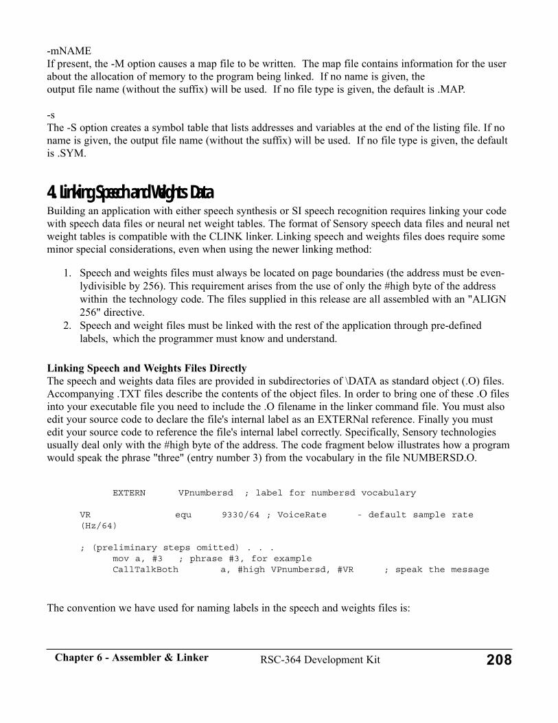
-mNAMEIf present, the -M option causes a map file to be written. The map file contains information for the userabout the allocation of memory to the program being linked. If no name is given, the output file name (without the suffix) will be used. If no file type is given, the default is .MAP.
-sThe -S option creates a symbol table that lists addresses and variables at the end of the listing file. If noname is given, the output file name (without the suffix) will be used. If no file type is given, the defaultis .SYM.
4. Linking Speech and Weights DataBuilding an application with either speech synthesis or SI speech recognition requires linking your codewith speech data files or neural net weight tables. The format of Sensory speech data files and neural netweight tables is compatible with the CLINK linker. Linking speech and weights files does require someminor special considerations, even when using the newer linking method:
1. Speech and weights files must always be located on page boundaries (the address must be even-lydivisible by 256). This requirement arises from the use of only the #high byte of the addresswithin the technology code. The files supplied in this release are all assembled with an "ALIGN256" directive.
2. Speech and weight files must be linked with the rest of the application through pre-definedlabels, which the programmer must know and understand.
Linking Speech and Weights Files DirectlyThe speech and weights data files are provided in subdirectories of \DATA as standard object (.O) files.Accompanying .TXT files describe the contents of the object files. In order to bring one of these .O filesinto your executable file you need to include the .O filename in the linker command file. You must alsoedit your source code to declare the file's internal label as an EXTERNal reference. Finally you mustedit your source code to reference the file's internal label correctly. Specifically, Sensory technologiesusually deal only with the #high byte of the address. The code fragment below illustrates how a programwould speak the phrase "three" (entry number 3) from the vocabulary in the file NUMBERSD.O.
EXTERN VPnumbersd ; label for numbersd vocabulary
VR equ 9330/64 ; VoiceRate - default sample rate(Hz/64)
; (preliminary steps omitted) . . . mov a, #3 ; phrase #3, for exampleCallTalkBoth a, #high VPnumbersd, #VR ; speak the message
The convention we have used for naming labels in the speech and weights files is:
208RSC-364 Development KitChapter 6 - Assembler & Linker
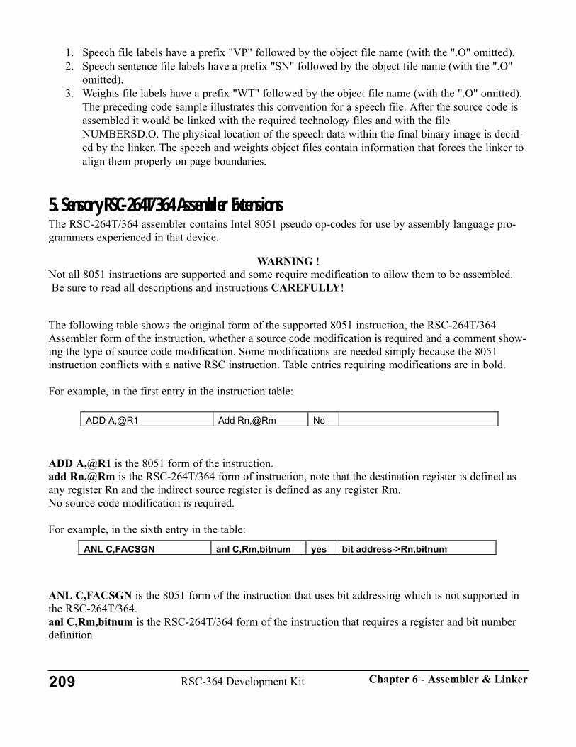
1. Speech file labels have a prefix "VP" followed by the object file name (with the ".O" omitted). 2. Speech sentence file labels have a prefix "SN" followed by the object file name (with the ".O"
omitted). 3. Weights file labels have a prefix "WT" followed by the object file name (with the ".O" omitted).
The preceding code sample illustrates this convention for a speech file. After the source code is assembled it would be linked with the required technology files and with the fileNUMBERSD.O. The physical location of the speech data within the final binary image is decid-ed by the linker. The speech and weights object files contain information that forces the linker toalign them properly on page boundaries.
5. Sensory RSC-264T/364 Assembler ExtensionsThe RSC-264T/364 assembler contains Intel 8051 pseudo op-codes for use by assembly language pro-grammers experienced in that device.
WARNING !Not all 8051 instructions are supported and some require modification to allow them to be assembled.Be sure to read all descriptions and instructions CAREFULLY!
The following table shows the original form of the supported 8051 instruction, the RSC-264T/364Assembler form of the instruction, whether a source code modification is required and a comment show-ing the type of source code modification. Some modifications are needed simply because the 8051instruction conflicts with a native RSC instruction. Table entries requiring modifications are in bold.
For example, in the first entry in the instruction table:
ADD A,@R1 is the 8051 form of the instruction.add Rn,@Rm is the RSC-264T/364 form of instruction, note that the destination register is defined asany register Rn and the indirect source register is defined as any register Rm.No source code modification is required.
For example, in the sixth entry in the table:
ANL C,FACSGN is the 8051 form of the instruction that uses bit addressing which is not supported inthe RSC-264T/364.anl C,Rm,bitnum is the RSC-264T/364 form of the instruction that requires a register and bit numberdefinition.
ADD A,@R1 Add Rn,@Rm No
209 RSC-364 Development Kit Chapter 6 - Assembler & Linker
ANL C,FACSGN anl C,Rm,bitnum yes bit address->Rn,bitnum

Source code modification is required.The modification is that the "bit address" is replaced with a register and bit number.
210RSC-364 Development KitChapter 6 - Assembler & Linker
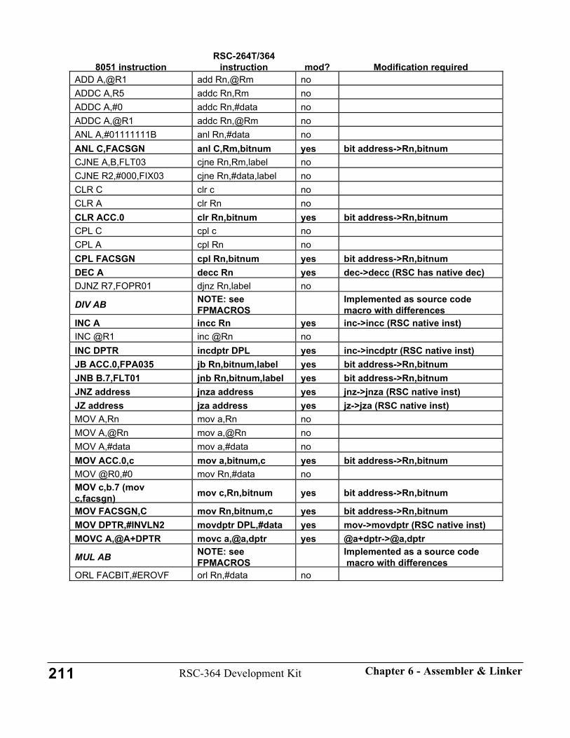
8051 instructionRSC-264T/364
instruction mod? Modification requiredADD A,@R1 add Rn,@Rm noADDC A,R5 addc Rn,Rm noADDC A,#0 addc Rn,#data noADDC A,@R1 addc Rn,@Rm noANL A,#01111111B anl Rn,#data noANL C,FACSGN anl C,Rm,bitnum yes bit address->Rn,bitnumCJNE A,B,FLT03 cjne Rn,Rm,label noCJNE R2,#000,FIX03 cjne Rn,#data,label noCLR C clr c noCLR A clr Rn noCLR ACC.0 clr Rn,bitnum yes bit address->Rn,bitnumCPL C cpl c noCPL A cpl Rn noCPL FACSGN cpl Rn,bitnum yes bit address->Rn,bitnumDEC A decc Rn yes dec->decc (RSC has native dec)DJNZ R7,FOPR01 djnz Rn,label no
DIV AB NOTE: seeFPMACROS
Implemented as source codemacro with differences
INC A incc Rn yes inc->incc (RSC native inst)INC @R1 inc @Rn noINC DPTR incdptr DPL yes inc->incdptr (RSC native inst)JB ACC.0,FPA035 jb Rn,bitnum,label yes bit address->Rn,bitnumJNB B.7,FLT01 jnb Rn,bitnum,label yes bit address->Rn,bitnumJNZ address jnza address yes jnz->jnza (RSC native inst)JZ address jza address yes jz->jza (RSC native inst)MOV A,Rn mov a,Rn noMOV A,@Rn mov a,@Rn noMOV A,#data mov a,#data noMOV ACC.0,c mov a,bitnum,c yes bit address->Rn,bitnumMOV @R0,#0 mov Rn,#data noMOV c,b.7 (movc,facsgn) mov c,Rn,bitnum yes bit address->Rn,bitnum
MOV FACSGN,C mov Rn,bitnum,c yes bit address->Rn,bitnumMOV DPTR,#INVLN2 movdptr DPL,#data yes mov->movdptr (RSC native inst)MOVC A,@A+DPTR movc a,@a,dptr yes @a+dptr->@a,dptr
MUL AB NOTE: seeFPMACROS
Implemented as a source code macro with differences
ORL FACBIT,#EROVF orl Rn,#data no
211 RSC-364 Development Kit Chapter 6 - Assembler & Linker

8051 instructionRSC-264T/364
instruction mod? Modification requiredORL A,R3 orl Rn,Rm noORL C,FACBTM orl c,facbit,6 yes bit address->Rn,bitnum
POP B pop Rn,@data_stack_ptr yes see stack instructions
PUSH ACC push @data_stack_ptr,Rn yes see stack instructions
RETI IRET yes reti->iretSETB C setb c noSETB b,7 (setbFACSGN) setb Rn,bitnum yes bit address->Rn,bitnum
SJMP FLT05 sjmp label noSUBB A,#FBIAS subb Rn,#data noSUBB A,R0 subb Rn,Rm noSUBB A,@R0 subb Rn,@Rm noXCH A,B xch Rn,Rm noXRL A,R4 xrl Rn,Rm no
212RSC-364 Development KitChapter 6 - Assembler & Linker

213
CHAPTER 7 - UPGRADES
This chapter describes the process of upgrading to the RSC-364 Development Kit withSensory Speech 6 Technology from Release 5.0 of the RSC-364.
• All new Library code is required. Sensory has tried to keep the Application Interface as familiaras possible, but there are minor changes.
• Minor changes are required to application level code to "port" it to Release 6• Adding new application-level features in Version 6 is straightforward.

1. Upgrading from RSC-364, Release 5.0
Summary of ChangesThe Overview chapter lists the new features in this release. In order to take advantage of these featuresyou will need to make the following changes:
• Modify application code to incorporate required feature changes (macro parameters, functionname changes)
• Optionally modify application code to incorporate new features available with this release• Optionally modify linker commands to incorporate modules containing new features
This section describes the required steps involved in the upgrade process and works through a sampleconversion. Be sure to read the Overview and other documentation sections for details that may not berepeated here. This release is intended to be a complete replacement of the previous (5.0) release. THETECHNOLOGY CODE IN RELEASE 6 IS NOT COMPATIBLE WITH THE RSC-164 OR RSC-264TAND WILL NOT RUN ON THOSE CHIPS. The sample conversion follows Sensory's recommendedmigration method. We suggest you work through the sample on your own system before beginning tomigrate your own application.
Most of the changes in version 6 are "transparent" and require no application-level changes.
Include FilesThe former \LIB364\MACROS\FASTDIG.INC is now named \LIB364\MACROS\DRT.INC. Thisreflects that Dual Recognition Technology now works with recognition sets other than Fast Digits. See Section 11 of Chapter 3, "Include and Link Requirements" for a summary of included file require-ments for all technology modules.
Linker CommandsThis release incorporates recognition improvements that require a change in the content of recognitionweights files; accordingly, any weights files must be upgraded. All the sample weights files included inthis release have been updated. If you are using custom weight files, contact Sensory about upgradingthem for Version 6 Technology.
The number and names of all technology object files remain the same, so no changes are required toapplication LINK.CMD or builder batch files.
Required Application ChangesDevelopers wishing to upgrade to Release 6 must make minor changes (described below) in any applica-tion to accommodate these technology changes:
1. The arguments for some technology macros have changed.2. Some parameters that previously had assembly-time binding now have run-time binding.
These technology-specific changes are required:
214 RSC-364 Development Kit Chapter 7 - Upgrades

1. If you use pattern generation or voice recording, remove all references to the macros LdCtl,InitSL, and GetSL, as well as code that tests the results of these macro functions. The speechframing feature of version 6 makes these functions obsolete
2. Provide a new argument to the pattern generation macro to specify how to deal with certainerrors. This parameter replaces the former NO_ERRORS constant. See Using Pattern Generationfor more discussion.
3. If you use the Prior macro function in Speaker Independent recognition, provide an additionalparameter to the macro to indicate how to treat the selected class. See Using SpeakerIndependent Speech Recognition for more discussion.
4. If you use Record and Play, provide an additional parameter to the RecordRP macro to specifythe threshold type. See Using Voice Record and Playback for more discussion.
5. Remove all references to the TemplateSize10 and TemplateSize16 macros. These functions havebeen automated.
6. If you use Continuous Listening 4, the technology is now called simply Continuous Listening.Remove any code related to the CheckSL macro. The cl_performance parameter is now suppliedas a run-time value to the Listen macro.
7. If you use Speaker Dependent recognition, provide a new argument to the RecogSD macro tospecify the performance level. This parameter replaces the former SD_PERFORMANCE con-stant. See Using Speaker Dependent Speech Recognition for more discussion.
8. If you use Speaker Dependent recognition to perform a "too close" test during training, changethe value of the "THRESHOLD_PLUS" parameter for the new SD weights. See Using SpeakerDependent Speech Recognition for more discussion.
9. If you use the SleepIO function, modify your code for the new, more general arguments. See thepassword sample for an example.
10. If your application uses local versions of STARTUP.A or CONFIG.A, compare your files withthe library versions in this release and incorporate any changes.
11. The Dual Recognition macro, RecogDrtDigit, is now more general and has been re-namedRecogDual. You must now supply an additional parameter to the macro to specify the extendedaddress bits (DRT now supports 24-bit template addresses).
Optional Application ChangesRefer to the appropriate "Using..." document for details on the improvements summarized below. Alsosee the sample programs as described.
1. If you already use the SPFlash memory handler, you should use the new library code. This willrequire minor application changes. The new SPFlash memory handler for SD has an applicationinterface similar to SRAM and SST flash; the version in 5.0 required different code flow.
2. Some developers will want to incorporate Wordspot SD technology, See Using Wordspot SDSpeech Recognition for more information.
3. Applications may take advantage of the multi-pin IO wakeup capability available in "sleepmode" in this release. See \LIB364\MACROS\SLEEP.INC for details.
4. Applications may take advantage of the generalized Dual Recognition Technology in this releaseto gain improved recognition. NOTE: DRT makes calls to validate_template_sdv. The oldSPFlash interface is not compatible with this use. To use DRT with SPFlash, you must use the
215RSC-364 Development KitChapter 7 - Upgrades

new handler.
IMPORTANTConversion of most applications can be completed in a few minutes. Be sure to make a backup of yourapplication code before beginning the conversion.
Sample Software ConversionAs a sample of the process of porting an application from the June 1999 release 5.0 RSC-364Development Kit to this version 6 release, we describe here converting the Speaker Dependent demo in\SAMPLES\SPKRDEP. An updated and improved version of this program with "name tagging" usingSPFlash appears in this kit under \SAMPL364\SPKRDEP, but here we "port" the Release 5.0 program touse the new library modules. As we will see, this conversion requires only minor editing ofSPKRDEP.A. As an example of the migration path for any application, we recommend:
1. First, install the Release 6 software in a new directory according to the instructions in the"Getting Started" section of the Overview Chapter. The following assumes the version 6 softwareis installed in directory C:\SENSORY, and the 5.0 software is in C:\DEVOLD.
2. Set the DOS environment variable, LibPath, to the root of this Sensory directory, and make sureyour DOS path includes this directory.
3. Copy the old sample, C:\LIBOLD\SAMPLES\SPKRDEP, to a new folder in your working direc-tory. For illustration, the following assumes this directory is called "X:\WORKING\SPKRDEP".
4. Change directory to the sample folder and work through the conversion.
This approach allows checking that the conversion works before any of the existing (old) library orapplication structure is touched. The editing changes are described below following the format:
<original data (removed or commented out)-->new data (replacement or added)
After installing the software and changing your DOS path, define the DOS environment variable,LibPath (use your own directory path name). The root of the Sensory directory contains a batch file,setlib.bat to simplify this - you type only the command in bold. This command also defines the environ-mental variable, casmspec, used by the assembler.
C:\sensory>setlib c:\sensory
C:\sensory>rem Sets the path of the root of Sensory's Library
C:\sensory>rem usage: SETLIB [path]
C:\sensory>set LibPath=c:\sensory
C:\sensory>set casmspec=-DLibPath:c:\sensory
C:\sensory>
Now create the new WORKING directory, copy the old SPKRDEP sample to the new
216 RSC-364 Development Kit Chapter 7 - Upgrades

WORKING\SPKRDEP directory on X: (do NOT copy to \SAMPL364\SPKRDEP or you will overwritethe new sample code.), and change to that directory.
X:\>md working
x:>cd working
X:\working>XCOPY D:\DEVELOLD\SAMPLES\SPKRDEP\*.* SPKRDEPDoes spkrdep specify a file nameor directory name on the target(F = file, D = directory)?dEng_seep.cmdEng_sram.cmdJap_seep.cmdJap_sram.cmdKor_seep.cmdKor_sram.cmdlnkflash.cmdpatgen_h.aPATGEN_H.Ospkrdep.a
10 File(s) copied
x:\working>cd spkrdep
x:\working\spkrdep>
Editing SPKRDEP.A:
First edit SPKRDEP.A to remove the macros LdCtl and InitSL. These functionsare automated in release 6. 524,525d523< LdCtl ;set up filters< InitSL
Next remove the code related to the GetSL macro, which is also automated in release 6. Make sure thatany code testing the macro results is also removed.
523a524,527> GetSL> cp a,#0 ;check if too noisy> jnz error>
The Patgen macro now takes an additional argument that specifies the "no errors" condition (similar tothe NO_ERRORS configuration constant in 5.0). To keep the operation the same as in 5.0 (all errors arereported), set the new parameter to 0. Note: in version 6 this parameter can be a run-time variable.
535c535< PatGen #STANDARD ---> PatGen #STANDARD, #0
217RSC-364 Development KitChapter 7 - Upgrades
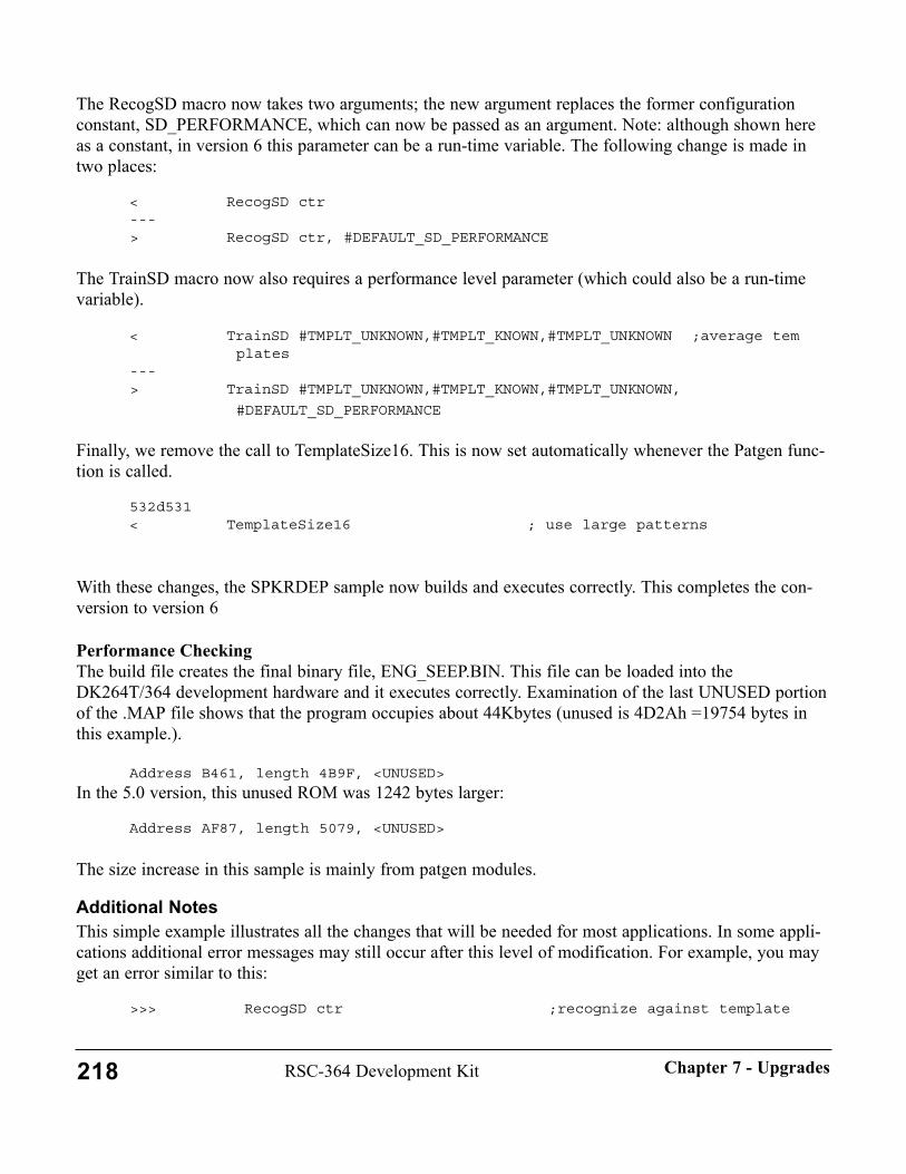
The RecogSD macro now takes two arguments; the new argument replaces the former configurationconstant, SD_PERFORMANCE, which can now be passed as an argument. Note: although shown hereas a constant, in version 6 this parameter can be a run-time variable. The following change is made intwo places:
< RecogSD ctr---> RecogSD ctr, #DEFAULT_SD_PERFORMANCE
The TrainSD macro now also requires a performance level parameter (which could also be a run-timevariable).
< TrainSD #TMPLT_UNKNOWN,#TMPLT_KNOWN,#TMPLT_UNKNOWN ;average templates
---> TrainSD #TMPLT_UNKNOWN,#TMPLT_KNOWN,#TMPLT_UNKNOWN,
#DEFAULT_SD_PERFORMANCE
Finally, we remove the call to TemplateSize16. This is now set automatically whenever the Patgen func-tion is called.
532d531< TemplateSize16 ; use large patterns
With these changes, the SPKRDEP sample now builds and executes correctly. This completes the con-version to version 6
Performance CheckingThe build file creates the final binary file, ENG_SEEP.BIN. This file can be loaded into theDK264T/364 development hardware and it executes correctly. Examination of the last UNUSED portionof the .MAP file shows that the program occupies about 44Kbytes (unused is 4D2Ah =19754 bytes inthis example.).
Address B461, length 4B9F, <UNUSED>
In the 5.0 version, this unused ROM was 1242 bytes larger:
Address AF87, length 5079, <UNUSED>
The size increase in this sample is mainly from patgen modules.
Additional NotesThis simple example illustrates all the changes that will be needed for most applications. In some appli-cations additional error messages may still occur after this level of modification. For example, you mayget an error similar to this:
>>> RecogSD ctr ;recognize against template
218 RSC-364 Development Kit Chapter 7 - Upgrades
list>>> ^Error in s2.A:474 -- Too few arguments for this macro call.
In such a case, refer to the Technology chapter for clarification of the proper macro arguments.
2. Upgrading from RSC-264T or RSC-164V2 Sensory does not supply separate upgrading instructions for chips outside the 364 family. If you areupgrading from an earlier release, contact Sensory.
219RSC-364 Development KitChapter 7 - Upgrades

220
CHAPTER 8 - DATABOOK

221
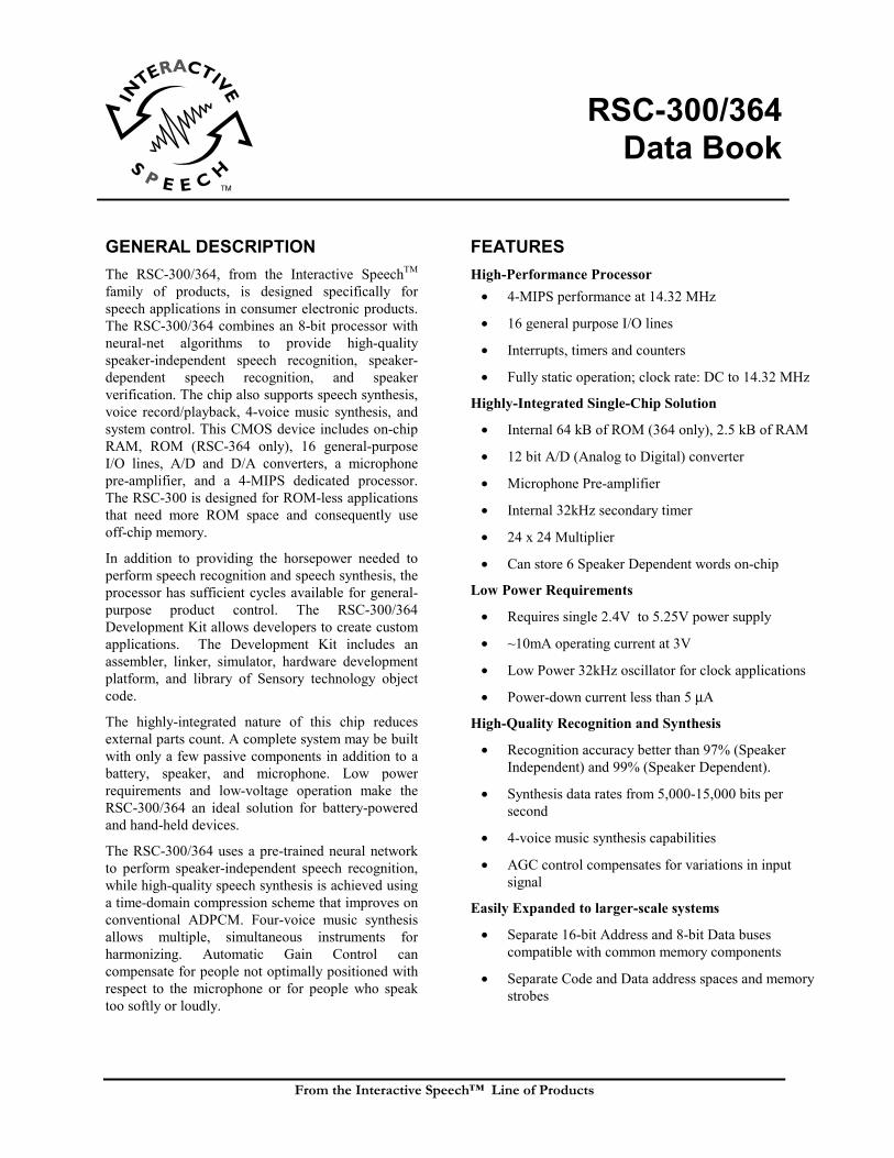
RSC-300/364Data Book
From the Interactive Speech™ Line of Products
GENERAL DESCRIPTIONThe RSC-300/364, from the Interactive SpeechTM
family of products, is designed specifically forspeech applications in consumer electronic products.The RSC-300/364 combines an 8-bit processor withneural-net algorithms to provide high-qualityspeaker-independent speech recognition, speaker-dependent speech recognition, and speakerverification. The chip also supports speech synthesis,voice record/playback, 4-voice music synthesis, andsystem control. This CMOS device includes on-chipRAM, ROM (RSC-364 only), 16 general-purposeI/O lines, A/D and D/A converters, a microphonepre-amplifier, and a 4-MIPS dedicated processor.The RSC-300 is designed for ROM-less applicationsthat need more ROM space and consequently useoff-chip memory.
In addition to providing the horsepower needed toperform speech recognition and speech synthesis, theprocessor has sufficient cycles available for general-purpose product control. The RSC-300/364Development Kit allows developers to create customapplications. The Development Kit includes anassembler, linker, simulator, hardware developmentplatform, and library of Sensory technology objectcode.
The highly-integrated nature of this chip reducesexternal parts count. A complete system may be builtwith only a few passive components in addition to abattery, speaker, and microphone. Low powerrequirements and low-voltage operation make theRSC-300/364 an ideal solution for battery-poweredand hand-held devices.
The RSC-300/364 uses a pre-trained neural networkto perform speaker-independent speech recognition,while high-quality speech synthesis is achieved usinga time-domain compression scheme that improves onconventional ADPCM. Four-voice music synthesisallows multiple, simultaneous instruments forharmonizing. Automatic Gain Control cancompensate for people not optimally positioned withrespect to the microphone or for people who speaktoo softly or loudly.
FEATURESHigh-Performance Processor
• 4-MIPS performance at 14.32 MHz
• 16 general purpose I/O lines
• Interrupts, timers and counters
• Fully static operation; clock rate: DC to 14.32 MHz
Highly-Integrated Single-Chip Solution
• Internal 64 kB of ROM (364 only), 2.5 kB of RAM
• 12 bit A/D (Analog to Digital) converter
• Microphone Pre-amplifier
• Internal 32kHz secondary timer
• 24 x 24 Multiplier
• Can store 6 Speaker Dependent words on-chip
Low Power Requirements
• Requires single 2.4V to 5.25V power supply
• ~10mA operating current at 3V
• Low Power 32kHz oscillator for clock applications
• Power-down current less than 5 µA
High-Quality Recognition and Synthesis
• Recognition accuracy better than 97% (SpeakerIndependent) and 99% (Speaker Dependent).
• Synthesis data rates from 5,000-15,000 bits persecond
• 4-voice music synthesis capabilities
• AGC control compensates for variations in inputsignal
Easily Expanded to larger-scale systems
• Separate 16-bit Address and 8-bit Data busescompatible with common memory components
• Separate Code and Data address spaces and memorystrobes

DATA BOOK RSC-300/364
From the Interactive Speech™ Line of Products
IMPORTANT NOTICESSensory reserves the right to make changes to or to discontinue any product or service identified in this publication at any time without notice inorder to improve design and supply the best possible product. Sensory does not assume responsibility for use of any circuitry other than circuitryentirely embodied in a Sensory product. Information contained herein is provided gratuitously and without liability to any user.
Reasonable efforts have been made to verify the accuracy of this information but no guarantee whatsoever is given as to the accuracy or as to itsapplicability to particular uses.
Applications described in this data sheet are for illustrative purposes only, and Sensory makes no warranties or representations that theInteractive SpeechTM line of products will be suitable for such applications. In every instance, it must be the responsibility of the user todetermine the suitability of the products for each application. Sensory products are not authorized for use as critical components in life supportdevices or systems.
Sensory conveys no license or title, either expressed or implied, under any patent, copyright, or mask work right to the Interactive SpeechTM lineof products, and Sensory makes no warranties or representations that the Interactive SpeechTM line of products are free from patent, copyright, ormask work right infringement, unless otherwise specified. Nothing contained herein shall be construed as a recommendation to use any productin violation of existing patents or other rights of third parties. The sale of any Sensory product is subject to all Sensory Terms and Conditions ofSales and Sales Policies.
June 2000
5 2 1 East Weddell DriveSunnyvale, CA 94089
TEL: (408) 744-9000FAX: (408) 744-1299
© 1999 SENSORY, INC.ALL RIGHTS RESERVED
P/N 80-0165-6Sensory is registered by the U.S. Patent andTrademark Office. All other trademarks of registeredtrademarks are the property of their respective owners.
RSC-300/364 DATA BOOK
From the Interactive Speech™ Line of Products
Table of Contents1. INTRODUCTION............................................................................................................................................... 1
2. RSC-300/364 HARDWARE SPECIFICATIONS............................................................................................. 3
3. USING THE RSC-300/364 ................................................................................................................................. 4
4. MEMORY ORGANIZATION........................................................................................................................... 5
5. MEMORY MAP ................................................................................................................................................. 6
6. GENERAL PURPOSE I/O................................................................................................................................. 6
7. INTERRUPTS..................................................................................................................................................... 8
8. RESET AND CLOCKS ...................................................................................................................................... 9
9. TIMERS AND COUNTERS .............................................................................................................................. 9
10. POWER DOWN AND WAKEUP OPERATION ...................................................................................... 10
11. ANALOG OUTPUTS ................................................................................................................................... 10
12. HARDWARE DEBUG FEATURES ........................................................................................................... 11
13. DESIGN CONSIDERATIONS .................................................................................................................... 13
14. OMNI-DIRECTIONAL MICROPHONE .................................................................................................. 14
15. POWER CONSUMPTION AND POWER SUPPLY CONSIDERATIONS ........................................... 17
16. DIE BOND PAD AND QFP PIN DESCRIPTIONS................................................................................... 18
17. DIE PAD RING............................................................................................................................................. 19
18. RSC-300/364 DIE BONDING PAD LOCATIONS .................................................................................... 20
19. ABSOLUTE MAXIMUM RATINGS ......................................................................................................... 21
20. D.C. CHARACTERISTICS ......................................................................................................................... 21
21. VDD vs. IDD................................................................................................................................................... 21
22. A.C. CHARACTERISTICS (EXTERNAL MEMORY ACCESSES) ...................................................... 22
23. TIMING DIAGRAMS .................................................................................................................................. 23
24. RSC-300/364 INSTRUCTION SET............................................................................................................. 24
25. RSC-300/364 SPECIAL FUNCTION REGISTER (SFR) SUMMARY ................................................... 27
26. SPECIAL DATA SPACE ADDRESSES SUMMARY............................................................................... 45
27. QUALITY AND RELIABILITY ................................................................................................................. 48
28. PACKAGING................................................................................................................................................ 50
29. ORDERING INFORMATION .................................................................................................................... 50

DATA BOOK RSC-300/364
From the Interactive Speech™ Line of Products 1
1. INTRODUCTION
The RSC-300/364 is the newest member in a family of high-performance 8-bit microprocessors featuring a high levelof integration, targeted to high-accuracy, low-cost speech recognition applications. The RSC-300/364 is designed tobring accuracy, fast response time and versatility to low-cost, power-sensitive consumer applications.
A design goal of the RSC-300/364 was to reduce total system cost while increasing system performance. Byincluding microphone signal amplification, data conversion, recognition and synthesis functionality, and ROM1
storage (RSC-364 only) with a CPU core on a single chip, dramatic cost and power reductions are achieved. Thus,the RSC-300/364 is able to provide 4 MIPS of integer performance at 14.32 MHz. This allows customerapplications to achieve maximum performance at minimum cost.
The CPU core embedded in the RSC-300/364 is an 8-bit, variable-length-instruction, microprocessor. Theinstruction set is somewhat similar to the Zilog™ Z8 having a variety of addressing mode mov instructions. TheRSC-300/364 processor avoids the limitations of dedicated registers by having completely symmetrical source anddestinations for all instructions. Of the 2.5 Kbytes of internal SRAM, 2 Kbytes are organized as a Data Space, and0.5 Kbytes is for register space. All arithmetic operation instructions may be applied to any register. Any pair ofadjacent registers (at an even address) may be used as the 16-bit pointer to either the source or destination for a datamovement instruction. Instruction classes allow the pointer to access internal or external Code Space, internalRegister Space, or external Data Space.
Architecturally, the RSC-300/364’s separate data and address buses allow use of standard EPROMs, ROMs, andSRAMs with little or no additional decoding. Provision for separate read and write signals for each external memoryspace further simplifies interfacing.
Creating applications using the RSC-300/364 requires the development of electronic circuitry, software code, andspeech/music data files (“linguistics”). This document provides detailed information on those aspects of the RSC-300/364 architecture that are important to product designers and programmers. It describes the physical interface tothe chip, printed circuit board layout and other design considerations, the RSC-300/364’s instruction set, andmemory organization. Refer to the RSC-300/364 Development Kit Manual for information on using Sensory’stechnology code for speech recognition, speaker verification, speech synthesis, and voice record and playback.Description of vocabulary development (“linguistics”) information is beyond the scope of this document and iscovered in a Design Note.
Custom Mask Capabilities of the RSC-364
The RSC-300 provides significant and flexible expansion capabilities through the use of external RAM or ROMProducts using the custom-mask version of the chip, the RSC-364, may save considerable per-unit cost by avoidingthe need for other active devices. The RSC-300 requires an external Code Space ROM memory to contain theprogram instructions, synthesis data, and Speaker Independent recognition weights. The custom-masked RSC-364with no additional external memory devices must rely on the fixed internal memory for all of its ROM and RAMrequirements. The internal ROM in the RSC-364 is application specific, with the amount available for userapplications decreasing as the number of synthesis words or other technology usage increases.
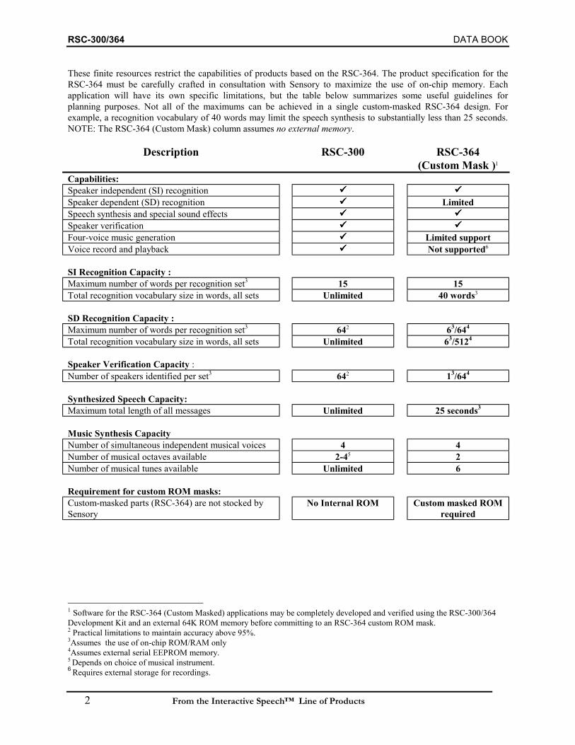
RSC-300/364 DATA BOOK
2 From the Interactive Speech™ Line of Products
These finite resources restrict the capabilities of products based on the RSC-364. The product specification for theRSC-364 must be carefully crafted in consultation with Sensory to maximize the use of on-chip memory. Eachapplication will have its own specific limitations, but the table below summarizes some useful guidelines forplanning purposes. Not all of the maximums can be achieved in a single custom-masked RSC-364 design. Forexample, a recognition vocabulary of 40 words may limit the speech synthesis to substantially less than 25 seconds.NOTE: The RSC-364 (Custom Mask) column assumes no external memory.
Description RSC-300 RSC-364(Custom Mask )1
Capabilities:Speaker independent (SI) recognitionSpeaker dependent (SD) recognition LimitedSpeech synthesis and special sound effectsSpeaker verificationFour-voice music generation Limited supportVoice record and playback Not supported6
SI Recognition Capacity :Maximum number of words per recognition set3 15 15Total recognition vocabulary size in words, all sets Unlimited 40 words3
SD Recognition Capacity :Maximum number of words per recognition set3 642 63/644
Total recognition vocabulary size in words, all sets Unlimited 63/5124
Speaker Verification Capacity :Number of speakers identified per set3 642 13/644
Synthesized Speech Capacity:Maximum total length of all messages Unlimited 25 seconds3
Music Synthesis CapacityNumber of simultaneous independent musical voices 4 4Number of musical octaves available 2-45 2Number of musical tunes available Unlimited 6
Requirement for custom ROM masks:Custom-masked parts (RSC-364) are not stocked bySensory
No Internal ROM Custom masked ROMrequired
1 Software for the RSC-364 (Custom Masked) applications may be completely developed and verified using the RSC-300/364Development Kit and an external 64K ROM memory before committing to an RSC-364 custom ROM mask.2 Practical limitations to maintain accuracy above 95%.3Assumes the use of on-chip ROM/RAM only4Assumes external serial EEPROM memory.5 Depends on choice of musical instrument.6 Requires external storage for recordings.
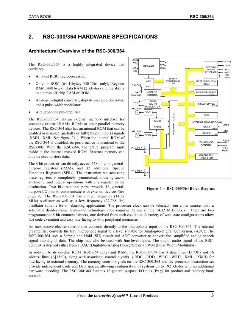
DATA BOOK RSC-300/364
From the Interactive Speech™ Line of Products 3
2. RSC-300/364 HARDWARE SPECIFICATIONS
Architectural Overview of the RSC-300/364
The RSC-300/364 is a highly integrated device thatcombines:
• An 8-bit RISC microprocessor.
• On-chip ROM (64 Kbytes, RSC-364 only), RegisterRAM (448 bytes), Data RAM (2 Kbytes) and the abilityto address off-chip RAM or ROM.
• Analog-to-digital converter, digital-to-analog converter,and a pulse width modulator.
• A microphone pre-amplifier
The RSC-300/364 has an external memory interface foraccessing external RAMs, ROMs or other parallel memorydevices. The RSC-364 also has an internal ROM that can beenabled or disabled (partially or fully) by pin inputs (signals-XMH, -XML; See figure 2). ). When the internal ROM ofthe RSC-364 is disabled, its performance is identical to theRSC-300. With the RSC-364, the entire program mustreside in the internal masked ROM. External memory canonly be used to store data.
The 8-bit processor can directly access 448 on-chip general-purpose registers (RAM), and 32 additional SpecialFunctions Registers (SFRs). The instruction set accessingthese registers is completely symmetrical, allowing movs,arithmetic, and logical operations with any register as thedestination. Two bi-directional ports provide 16 general-purpose I/O pins to communicate with external devices (Seepage 6). The RSC-300/364 has a high frequency (14.32MHz) oscillator as well as a low frequency (32,768 Hz)oscillator suitable for timekeeping applications. The processor clock can be selected from either source, with aselectable divider value. Sensory’s technology code requires the use of the 14.32 MHz clock. There are twoprogrammable 8-bit counters / timers, one derived from each oscillator. A variety of wait state configurations allowfast code execution and easy interfacing to slow peripheral memories.
An inexpensive electret microphone connects directly to the microphone input of the RSC-300/364. The internalpreamplifier converts the tiny microphone signal to a level suitable for Analog-to-Digital Conversion. (ADC), TheRSC-300/364 uses a Sample and Hold (SH) circuit and ADC converter to convert the amplified analog speechsignal into digital data. The chip may also be used with line-level inputs. The output audio signal of the RSC-300/364 is derived either from a DAC (Digital-to-Analog Converter) or a PWM (Pulse Width Modulator).
In addition to its on-chip ROM (RSC-364 only) and RAM, the RSC-300/364 has 8 data lines (D[7:0]) and 16address lines (A[15:0]), along with associated control signals (-RDC, -RDD, -WRC, -WRD, -XML, -XMH) forinterfacing to external memory. The memory control signals on the RSC-300/364 and the processor instruction setprovide independent Code and Data spaces, allowing configuration of systems up to 192 Kbytes with no additionalhardware decoding. The RSC-300/364 features 16 general-purpose I/O pins (Px.y) for product and memory bankcontrol.
PRE-AMP EXTERNALMEMORY
INTERFACE
CPU
TIMING ANDCONTROL
32K x 8
32K x 8
HIGH
LOW
INTERNAL ROM (RSC-364)
A[15:0]
D[7:0]
-RDC
-WRD-RDD-WRC
448 bytes
8 levels
-XMH
-XML
-RESET
-TE1/PWM
STACK SPACE
REGISTER SPACE
BREAK POINTREGISTER
AiFE1
ANALOGCONTROL
ADC
TIMER1
TIMER2
OSC1
OSC2
POR
T0
INTE
RR
UPT
LO
GIC
DACOUT
XI1, XO1
XI2, XO2
P0.0-P0.7
P1.0-P1.7
DAC
PULSEWIDTH
MODULATOR
POR
T1
AOFE3AiN1
AOFE2
AOFE1
AiNØ
AiFE2
PWM
BUFOUT/
SPEECHPROCESSING
UNIT2K TECHNOLOGY
SRAM
Figure 1 -- RSC-300/364 Block Diagram

RSC-300/364 DATA BOOK
4 From
3. USING THE RSC-300/364Creating applications using the RSC-300/364 requires the development of electronic circuitry, software code, andspeech/music data files. Software code for the RSC-300/364 can be developed by Sensory or by externalprogrammers using the RSC-300/364 Development Kit. For more information about development tools andservices, please contact Sensory, or visit www.SensoryInc.com. A typical product will require about $0.30 - $1.00(in high volume) of additional components, in addition to the RSC-300/364.
The following sample circuit provides an example of how the RSC-300/364 might be used in a low volumeconsumer electronic product. The external ROM contains the application program, recognition weights, and speechdata. A high volume application would likely use an RSC-364 (custom-masked ROM), and would not require theseparate ROM.
Figure 2 – Reference Circuit
VDD
VDD
VDD
VDD
VDD
P0.4P0.3P0.2P0.1P0.0
D6
A9
A1
D4
A12
A4
P0.
6
D3
A5
A10
P0.
7P
1.0
D7
A2
A15
A7
P1.
5
D0
D5
D1
A8
P1.
7
A14A13
P1.
6
A0
A3
P1.
2P
1.3
P1.
4
P1.
1
D2
A11
A6
/XMH/XML
P0.5
/RDCPDN
C2220pF
C34700pF
C10.1uF
C4100uF
R5100K
R12.7K
C100.1uF
R4100K
C968pF
C70.022uF
R2100
C50.1uF
U1
AT27LV512A(TSOP)
109876543
252421232
26271
2022
1112131516171819
A0A1A2A3A4A5A6A7A8A9A10A11A12A13A14A15
CEOE
D0D1D2D3D4D5D6D7
R32.7K(TBD)
J1
INPUT-MIC
C6100uF/16V
RSC364
123456789
29
12
13
14
15
16
17
18
202122232425262728
30313233
47
46
45
5556
6162
42
41
40
39
38
37
363534
63
72
60595857
19
54
53
52
51
50
49
48
7170696867666564
11
10
43
44
AIF
E2
DA
CA
OFE3
AIN
1A
IN0
AO
FE2
GN
DP0
P1/T
E
Vdd
D7
D6
D5
D4
D3
D2
D1
A15A14A13A12A11A10A9A8GND
A7A6A5A4
P1.5
P1.6
P1.7
P0.5P0.4
VddGND
RS
TX
I1X
O1
XI2
XO
2A
0
A1A2A3
RDC
AOFE1
P0.0P0.1P0.2P0.3
D0
P0.6
P0.7
P1.0
P1.1
P1.2
P1.3
P1.4
AIFE1VrefXMLXMHPDN
WRDRDDWRC
NC
NC
NC
NC
C140.01uF
LS1
SPEAKER
C130.1uF
C80.1uF
R747
C140.01uF
R6400
C1227 pF
C1127pF
Y1
14.318MHz
/RDC
PDN/WRD/RDD/WRC
Note: Applications using the PWM output may not meet FCC or CE (such as EN55022 Class A or B) standards for radiated emissions. Forapplications that must meet these standards, Sensory recommends turning off the PWM in the application software, and using an externalaudio power amplifier connected to the DAC output. Please refer to Sensory's Application Note 80-0105 "DAC Output" for sample circuitsand design guidelines."
the Interactive Speech™ Line of Products

DATA BOOK RSC-300/364
From the Interactive Speech™ Line of Products 5
4. MEMORY ORGANIZATIONInternal ROM Memory (RSC-364 only)Internal ROM is organized as two banks of 32 Kbytes each, both mapped into code space. Either of the two internalbanks may be independently disabled using external inputs; input pin -XML disables the lower 32K [0000h-7FFFh]bank, while input pin -XMH disables the upper 32K [8000h-FFFFh] bank. When a bank is disabled, read accesses toit are directed to off-chip code space. In most applications the -XML and -XMH signals will both be grounded (foruse with external ROM program memory) or both will be left floating (to use internal ROM memory for programmemory). Write accesses to the code space are directed to external memory off-chip. Except for specific addresses inthe last page of memory (described on page 6), read and write accesses to data space are always directed to externalmemory.
External MemoryThe RSC-300/364 allows for extended message lengths and expanded program functionality by using externalmemory. There are 30 pins that provide an interface between the RSC-300/364 and external ROM or RAM. The 16address line outputs, A[15:0], are shared for accesses to external code space or data space. The 8 data lines, D[7:0],are bi-directional, and are normally inputs except when there is a write to external memory. Refer to MEMORY MAP(on page 6) for details on accessing external code and data spaces through movc and movx instructions.
The RSC-300/364 uses the -RDC, -WRC, -RDD and -WRD signals to strobe data to or from memory or I/O devices.The -RDC and -WRC strobes are provided for accessing code space, while the -RDD and -WRD strobes are used toaccess data space. These four memory strobes are all active low (see page 23 for timing information). Using thesestrobes, the RSC-300/364 can directly access 64K of external code space (either internal or external) and 64K ofexternal data space. External memory and I/O devices can reside in code space (RSC-300 only) or data space, asdetermined by the user application. Executable code must reside in code space; tables and other data may reside incode space or data space. Using I/O bits, additional external decoding can be used to bank select between multipleRAMs or ROMs. This method allows for external Data Space storage requirements larger than the combined 128Kaddressed directly by the RSC-300/364. Figure 3 below illustrates a typical large Data Space ROM-only memoryconfiguration. The lowest 64K bank is addressed as Code Space, and the other 7 banks are addressed as Data Space.The ROM is selected by both -RDD and -RDC. Additional logic may be required to use both ROM and RAM/Flashin external Data Space.
Addr (0 - 15)
Addr 16
Data
/CE
/OE
Addr 17
Addr 18P0.4
P0.3
P0.2
/RDD
/RDC
Data
Addr(0 - 15)
A18
A17
A16
4 MbitROM
RSC-300/364
Figure 3 -- Large ROM Decoding
Sensory's RSC-300/364technology code requirescode execution at 14.3 MHzwith one wait state. ExternalROM Code memory speedsshould be 120 nS or faster.External Data Space accessspeed may be independentlycontrolled by the insertion ofadditional wait states formovx instructions, simplifyingaccess to slow read/writedevices.

RSC-300/364 DATA BOOK
6 From the Interactive Speech™ Line of Products
5. MEMORY MAPThe RSC-300/364 has three address spaces: Code Space, Data Space, and Register Space. Code space is typicallyROM. Data space may be ROM, RAM, Flash, or other parallel read/write memories. Register space is limited to on-chip SRAM. The instruction set provides separate instructions for accessing each space. Executable code must residein code space; tables and other data may reside in code space or data space. Register space is intended primarily forvariables.
The internal ROM (RSC-364 only) and off-chip code space memory (RSC-300 only) may be accessed using movcinstructions. The off-chip data space is accessed using movx instructions, while the on-chip register space is accessedusing mov instructions. Writes to code space are always directed off-chip.
The internal ROM (RSC-364 only) is organized as two code space banks of 32 Kbytes each. The banks can beindependently disabled using external inputs: the low bank (address range 0000h-7FFFh) can be disabled byasserting pin input -XML while the high bank (address range 8000h-FFFFh) can be disabled by asserting pin input -XMH. This feature may be used to expand External addressable code space beyond 64 Kbytes.
The SRAM register space supports 8-bit addresses, so only 256 bytes may be directly addressed. General-purposeregisters are located between addresses 000h and 0BFh. A 32-byte bank of SFRs (special function registers) residesat addresses 0E0h-0FFh. The 32-byte bank at addresses 0C0h-0DFh may be mapped to any of the six lower 32-bytebanks in page 0 (addresses 000h through 0BFh), or to eight additional 32-byte banks in page 1 (addresses 100h-1FFh. A special function register controls this mapping, providing a total of 448 bytes of SRAM register space. TheRSC-300/364 also contains 2 Kbytes of internal data space RAM that is reserved for technology use.
Off-chip memory (and memory-mapped I/O) is accessed using a 16-bit address bus and an 8-bit data bus. Separateread / write strobes are generated for access to external code and data spaces. This allows the RSC-300/364 todirectly access 64 Kbytes of external code memory and 64 Kbytes of external data memory. Bank switching iscommonly implemented using I/O pins to select additional off-chip memory.
Certain addresses in the range of 0FF00h-0FFFFh of DataSpace are mapped internally, so addresses in this last page ofdata space are not generally accessible. (See Page 45)
The RSC-300/364 allows software to adjust the speed of off-chip memory access. This allows using fast memory forperformance needs or (if feasible) slower memory for costsavings. The off-chip memory access time can be stretchedusing wait states defined by the BANK register, and thesoftware can dynamically change the wait state valuedepending on the particular memory or I/O peripheral. Waitstates for external Data Space may be selected independentlyof Code Space wait states.
There is modest stack space on chip. The stack is required forinterrupts and allows a limited number of nested calls.Programmers are encouraged to write inline code instead ofmaking deeply-nested subroutine calls. The RSC-300/364offers limited support for a software stack to allow moredeeply nested calls or to store parameters, although this is notusually required. Macros using this software stack areaccessible to developers.
6. GENERAL PURPOSE I/O
32K x 8
32K x 8HIGH [8000h-FFFFh]
LOW [0000h-7FFFh]
RSC-364 Int ROM-XMH
-XML
movc (Read Access)
MAPPED RAM BANK
REGISTER SPACE
0C0h
0E0h
100h
mov000h
SPECIAL FUNCTIONREGISTERS
1FFh
OFF-CHIPADDRESS SPACE
64K x 8 Code Space movc (Write Access)
64K x 8 Data Space movx
-RDC-WRC-RDD-WRD
STACK SPACE
(Reserved)
Mapped toRAM Bank
DATA BOOK RSC-300/364
From the Interactive Speech™ Line of Products 7
The RSC-300/364 has 16 general purpose I/O pins (P0.0-P0.7, P1.0-P1.7). Each pin can be programmed as an inputwith weak pull-up (~200KΩ equivalent device); input with strong pull-up (~10KΩ equivalent device); input withoutpull-up, or as an output. This is accomplished by having 32 bits of configuration registers for the I/O pins (PortControl Register A and Port Control Register B for ports 0 and 1). (See page 27)
After reset, all of the I/O pins are set to be inputs with weak pull-ups. Designers may make use of this start-up featureto assure enabling or disabling of particular functions controlled by I/O pins.
For electrical specifications regarding the general purpose I/O pins, please refer to D.C. CHARACTERISTICS. AllI/O pins are diode clamped to VDD and ground, and are capable of sinking up to 200 mA if VDD is exceeded.
In addition to providing general purpose I/O, port 0 bit P0.0 can serve as an interrupt input (using IMR and IRQregisters). Any I/O pin may be used as a “wakeup” event when the chip is in “sleep” mode.
Typically some of the I/O pins may be used for extended address bits in larger systems having more than 64K ofmemory. This may be done by connecting port pins directly to Address bit 16 and higher pins of large memorydevices.
RSC-300/364 DATA BOOK
8 From the Interactive Speech™ Line of Products
7. INTERRUPTS
The RSC-300/364 allows for six interrupt sources, as selected by software. Each has its own mask bit and request bitin the IMR and IRQ registers respectively. The global interrupt enable flag, which enables or disables all interrupts,is located in the FLAGS registers. Bit assignments for the IMR and IRQ registers are listed on page 43. Thefollowing events can generate interrupts:
• Positive edge on Port 0, bit 0
• Overflow of Timer 1
• Overflow of Timer 2
• Two Sensory Proprietary functions
• Completion of PWM sample period
If an IRQ bit is set high and the corresponding IMR bit is set high and the global interrupt enable bit is set high, aninterrupt will occur. Interrupts cannot be nested. The flags register is copied to a holding register and then theglobal interrupt enable is cleared, preventing subsequent interrupts until the IRET instruction is executed. The IRETinstruction will restore the flags register from the holding register.
If the corresponding mask register bit is clear, the IRQ bit will not cause an interrupt. However, it can be polled byreading the IRQ register. IRQ bits can be cleared by writing a 0 to the corresponding bit at address 0FEh (the IRQregister). IRQ bits can not be set by writing to 0FEh. Writing a one is a no-op.
The IRQ bits must be cleared within the interrupt handler by an explicit write to the IRQ register rather than by animplicit interrupt acknowledge.
Important: clear interrupts this way:mov IRQ, #BITMASK ; right
not this way:and IRQ, #BITMASK ; wrong
The ‘and’ instruction is not atomic, it is a read-modify-write. If an interrupt occurs during an ‘and IRQ’ operationthe interrupt will be cleared before it is seen, possibly disabling the interrupt until the system is reset.Because you cannot set bits in the IRQ register, a ‘mov IRQ’ is a safe, effective, and atomic way to clear bits in theIRQ register. Use it the way you would use an ‘and’ in other registers.
Note: if Port 0.0 (the external IRQ) is set as an output, the external IRQ flag will be set if the output is driven from 0to 1 under program control.
For each interrupt, execution begins at a different code space address:
Interrupt #0 Address 4Interrupt #1 Address 8Interrupt #2 Address 0ChInterrupt #3 Address 10hInterrupt #4 Address 14hInterrupt #5 Address 18h
Normally the instruction at the interrupt address is a jump to an Interrupt Service Routine (ISR). This jump is calleda vector. The vectors located at each of these addresses are typically in ROM. .

DATA BOOK RSC-300/364
From the Interactive Speech™ Line of Products 9
8. RESET AND CLOCKS
ResetThe reset pin, -RESET, is an active low Schmitt trigger input. The reset pin is provided with hysteresis in order tofacilitate power-on reset generation via an RC network. Reset is held internally for 10 msec after the -RESET inputsignal is de-asserted. This allows the oscillator to stabilize before enabling other processor subsystems. The -RESETsignal must be asserted for a minimum of 2 clock periods.
OscillatorsTwo independent oscillators in the RSC-300/364 provide a high-frequency clock and a 32 kHz time-keeping clock.The oscillator characteristics are as follows:
Oscillator #1 Pins XI1 and XO1 14.32 MHz
Oscillator #2 Pins XI2 and XO2 32,768 Hz
Oscillator #1 works with an external crystal, a ceramic resonator, or LC. Use of Oscillator #2 requires a crystal forprecise timekeeping.
Each oscillator has an enable control. When disabled, the inverter is high-impedance, and a weak pull-up device(~100 KΩ) holds the inverter output high. Both oscillators are controlled by the Clock Control Register (CPUregister 0E8h). By default, Oscillator #1 is enabled by reset, while Oscillator #2 is disabled by reset. The effect ofreset therefore requires that Oscillator #1 be functional in all designs. The Clock Control Register also determinesinternal division of the CPU clock source (see below).
Each oscillator has an associated timer that is fully programmable. The RSC-300/364 timers are described in thefollowing section.
Processor ClockThe RSC-300/364 uses a fully static core; the processor can be stopped (by removing the clock source) and restartedwithout causing a reset or losing contents of internal registers. Static operation is guaranteed from DC to 14.32 MHz.The processor clock is selected from either the Oscillator #1 output (gated by wake-up 10 mS delay) or the Oscillator#2 output, based on bit 2 of the Clock Control Register. This bit is cleared by reset, which selects Oscillator #1. It isthe responsibility of the firmware not to select Oscillator #2 until both oscillators have been enabled and stabilized.
After source selection, the processor clock can be divided-down in order to limit power consumption. Bits 3 and 4 ofthe Clock Control Register determine the divisor for the processor clock. Between zero and seven wait states mustalso be selected for the processor clock. Wait states are inserted on reads or writes to all addresses except RegisterSpace RAM and, under certain configurations, internal ROM (RSC-364 only).
Sensory technology code must run with a processor clock of 14.32 MHz, a clock divisor of one, and one wait state.This creates internal RAM cycles of 70 nsec duration and internal ROM (RSC-364 only) or external cycles of 140nsec duration. Careful design of external decoding logic and close analysis of gate delays may allow operation withCode Space memories having 120 nsec access times. Additional wait states may be selected for external Data Spaceaccess.
9. TIMERS AND COUNTERS
The two independent oscillators of the RSC-300/364 provide counts to two internal timers. Each of the two timersconsists of an 8-bit reload value register and an 8-bit up-counter. The reload register is readable and writeable by the
RSC-300/364 DATA BOOK
10 From the Interactive Speech™ Line of Products
processor. The counter is readable with precaution taken against a counter change in the middle of a read. If theprocessor writes to the counter, the data is ignored. Instead, the counter is preset to the reload register value. That is,any write to a counter will cause it to be reloaded. This is the usual way of initializing the counter. When the timeroverflows from FF to 00, a pulse is generated that sets IRQ #0 (timer #1) or IRQ #1 (timer #2). If the correspondingIMR bit is set and the Global Interrupt Bit is set, an interrupt will be generated. Instead of overflowing to 00, thecounter is automatically reloaded on each overflow.
For example, if the reload value is 0FAh, the counter will count as follows:
0FAh, 0FBh, 0FCh, 0FDh, 0FEh, 0FFh, 0FAh, 0FBh etc.
The overflow pulse is generated during the period after the counter value was 0FFh.
Timer #2 may be used as a wakeup when the processor has powered-down.
Refer to the following registers for more information about using timers and counters:
T1R: Timer 1 Reload Register (page 34)T1V: Timer 1 Counter Register (page 34)T2R: Timer 2 Reload Register (page 35)T2V: Timer 2 Counter Register (page 35)
10. POWER DOWN AND WAKEUP OPERATIONThe RSC-300/364 can be powered down through software by setting the PD bit (bit7) of the Clock Control Register(See page 33). Setting this bit halts the processor until a “wakeup” event clears the bit. The instruction that causesthe power down event may also set or clear other bits in the Clock Control Register to enable or disable any of theclocks, and to select a clock to be used as the processor clock upon wakeup. A wakeup event can be generated fromeither of two sources:• bit transition(s) of port 0 or port 1 pins, or• an overflow pulse from timer 2.
For low power consumption, oscillator #1 (bit 0) and the FC clock (bit 5) should always be disabled during powerdown. Oscillator #2 (bit 1) must be enabled if the wakeup condition is a timer 2 event. If the wakeup event is an IOpin event, all clocks should be disabled for lowest power consumption.
If oscillator #1 is disabled during power down, and the selected processor clock source is oscillator #1, then awakeup event will require that oscillator #1 be started and stabilized before its output can be used as the processorclock. The oscillator is started when the wakeup event clears bit 0 of the Clock Control Register, but the processorclock is delayed by 10 milliseconds to assure stability.
If the RSC-300/364 is powered down with oscillator #2 selected as the processor clock source, a timer2 wakeupevent does not require a delay because it is assumed that oscillator #2 is running and stable. Due to long startup timefor oscillator #2, the RSC-300/364 should not be powered down with oscillator #2 disabled and selected as theprocessor clock.
A wakeup event does not cause a reset. The processor, which was “stopped-in-its-tracks” when the PD bit was set, isrestarted without loss of context.
11. ANALOG OUTPUTSThe RSC-300/364 offers two separate options for analog output. The DAC (Digital to Analog Converter) outputprovides a general-purpose 10-bit analog output that may be used for speech output (with the inclusion of an audio

DATA BOOK RSC-300/364
From the Interactive Speech™ Line of Products 11
amplifier), or that may be used for other purposes requiring an analog waveform. Many speech applications mayrequire only driving a small speaker, however, and cost can be saved in these applications by using the Pulse WidthModulator (PWM) outputs of the RSC-300/364 instead of the DAC output.
Special Note: Applications using the PWM output may not meet FCC or CE (such as EN55022 Class A or B)standards for radiated emissions. For applications that must meet these standards, Sensory recommends turning offthe PWM in the application software, and using an external audio power amplifier connected to the DAC output.Please refer to Sensory's Application Note 80-0105 "DAC Output" for sample circuits and design guidelines.
DAC OutputThe digital-to-analog converter (DAC) provides its output through DACOUT, with an output impedance of 22KΩ.VDACOUT can swing from 0V to VDD. An external audio amplifier and optional volume control must be used to drive aspeaker. Filtering above 5 kHz is recommended to provide the correct frequency response.
PWM OutputThe two PWM outputs are designed for driving a 32-Ohm speaker at audio frequencies. These signals produce goodquality audio with no additional components. These outputs are actually digital outputs that produce a series of highfrequency pulses at varying rates that, when filtered by the mechanical dynamics of a speaker, create the effect of acontinuously varying analog signal.
Although it is called a pulse width modulator, the RSC-300/364 actually incorporates a pulse count modulator: aprogrammable number of pulses is produced during each sample period. The two PWM outputs connect directly tothe two speaker terminals. During operation, the first of the two signals will be at ground and the second will have apulse train. The pulses will cause the speaker cone to push out (or pull in, depending on the wiring connections). Ifthere are many pulses in a sample period, the speaker will push out a large amount; if there are few pulses, thespeaker will push out just a little. Switching the pulse train to the first output and holding the second output at groundeffectively reverses the polarity of the signals, so now the speaker will pull in. By controlling the number of pulses ineach sample period and the output on which they appear, the speaker can be made to move in and out as required toreproduce an audio waveform.
The PWM0 pin is shared with the BUFOUT signal, and the PWM1 pin is shared with the -TE signal. At power-on,these pins are configured for non-PWM operation. The BUFOUT and -TE signals are both test signals that aretypically not used during normal operation. When the Pulse Width Modulator is enabled via software, the pins areswitched over to the PWM function. See page 46 for information about programming the PWM. (Typically thePWM is controlled by Sensory library code, so there is little need for application programs to alter it.)
12. HARDWARE DEBUG FEATURESSpecial debugging hardware has been incorporated into the RSC-300/364 to assist developers in producing codequickly. The specialized circuitry provides the following features:
• A 16-bit break register that holds one ROM breakpoint address
• A TRAP bit in the Flags register (Address 0FFh) that enables or disables the breakpoint.
• A vector at 0FFF8h to which the processor is directed when the Program Counter equals the breakpoint addressand the TRAP bit is enabled. The break occurs before execution of the instruction at the breakpoint address.
• A special page of Code Space (0FF00h-0FFFFh) for holding the resident debugger software. When this page isentered via a break, timers and interrupts are suspended. When execution resumes outside this page, timers andinterrupts are restored. Entering this page by means other than a break has no special effect, and timers andinterrupts continue to operate as normal.
RSC-300/364 DATA BOOK
12 From the Interactive Speech™ Line of Products
• A vector at 0FFFCh to which the processor is directed if the -TE pin is held low at power-on. This provides ameans for starting up in the debugger.
The debug circuitry, in conjunction with debug monitor software resident in the last page of Code ROM, allowsexamining the contents of Register, Code, and Data Space addresses. Register space contents may be modified, asmay Data or External Code space addresses if implemented in a RSC-writeable device.
Additionally, the RSC-300/364 supports a 4-byte, bi-directional communication interface using external hardwareregisters. This interface provides one means for another computer to interact with the resident debug monitor.
Sensory expects to provide debugging support for the RSC-300/364 at some future date.

DATA BOOK RSC-300/364
From the Interactive Speech™ Line of Products 13
13. DESIGN CONSIDERATIONSSpeech recognition accuracy can be degraded by a number of factors. A common problem that causes accuracydegradation is noise: both electrical noise within the system and audio noise picked up by the microphone. A majorinnovation in the RSC-300/364 is the incorporation of an audio preamp circuit right on the chip. The signal from atypical electret microphone is of the order of a few millivolts, and an overall preamp gain of 200 or more is neededto make this signal useable by the RSC. The RSC-300/364 requires only a few external passive components toprovide this amplification. Good grounding practice and elimination of crosstalk into the analog circuitry will furtherhelp ensure good recognition accuracy. Product design that encourages the user to speak loudly and close to themicrophone helps attain a good signal-to-noise ratio.
Analog Design
The schematic in Figure 5 illustrates a reference input audio preamp design for use with the RSC-300/364. Themicrophone resistor shown as 2.7K has a large influence on the system gain, so the value will depend on thesensitivity of the microphone. The value of 2.7K is typical.
VDD
100uF
100
2.7K
0.022uF
2.7K0.1uF
4700pF
100uF
220pF
AIFE2
AOFE1
AIFE1
VDD
VREF
Microphone
AIN1
AOFE3
AIN0
RSC-300/364470.01uF
AOFE2
Figure 5 -- Preamplifier Schematic
Some applications may use the RSC-300/364 with input signals from a device other than an electret microphone. Forassistance with such designs, contact Sensory.
RSC-300/364 DATA BOOK
14 From the Interactive Speech™ Line of Products
PCB DesignA double-sided printed circuit board (PCB) with ground plane is recommended. The ground plane should cover theanalog circuitry area and only be tied to ground near the RSC device. In order to reduce crosstalk, the analog anddigital circuits should be physically separated as far as is practical. Take special care to keep high-speed clockedlines (e.g., address and data) away from the microphone components and traces.
A 0.1 µF bypass capacitor should be installed immediately next to each digital IC and near the VDD pins of the RSCchip. The bypass capacitors should be stacked or monolithic ceramic type, rated at 50 volts. If a three-terminalvoltage regulator (such as a 7805) is used, tantalum bypass capacitors should be connected close to the regulatorbetween the input/output pins and ground.
In a practical application using replaceable AA or AAA batteries, incorporating a protection diode in series with thepower supply will avoid damage to the circuit if batteries are inserted with the wrong polarity.
If the RSC is used in a system with other digital clocks (switching power supplies, LCD driver, etc.) take special careto prevent these signal from getting into the audio circuitry of the RSC.
Locating and Mounting the RSC-300/364The RSC-300/364 is supplied as a bare, tested die or in a 64 lead, 10 x 10 x 1.4 mm TQFP package. The die formmay be wire bonded directly to the main PCB or, in some cases, may be bonded to a separate chip-on-board (COB)circuit board. In production this COB assembly may be functionally tested, then attached to the main board as aworking module.
There are several methods of attaching the COB to the main board, and a careful choice should be made by thedesigner. The RSC-300/364 is a 72-pad device requiring good attaching methodology for correct operation. Sincecost is always a consideration, COB boards may often be designed as single-sided PCBs.
The simplest way of attaching a single-sided COB to a main board is to lay it, chip side up, on the main board andmake solder bridges from the main board up along the thickness of the COB to the electrical contacts on the top ofthe COB board. In production this is not a reliable technique.
A second technique is to use wires or pins to connect thru-holes between the main board and the COB. This reliabletechnique may be more time consuming.
A third technique is to put a hole in the main board at the center of the COB location and to mount the COB to themain board UPSIDE DOWN, that is, with the chip facing down into the hole. Then the COB and main boards maybe soldered together. In this case, the orientation of the signal leads of the RSC-300/364 is different from that of theother arrangements.
14. OMNI-DIRECTIONAL MICROPHONESelecting a Suitable MicrophoneFor most applications, an inexpensive omni-directional electret capacitor microphone with a minimum sensitivity of -60 dB is adequate. In some applications, a directional microphone might be more suitable if the signal comes from adifferent direction than the audio noise. Since directional microphones have a frequency response that depends ontheir distance from the sound source, such microphones should be used with caution. For best performance, speechrecognition products should be used in a quiet environment with the speaker’s mouth in close proximity to themicrophone. If the product is meant to be used in a noisy environment, care should be taken to design around thenoise. Improving the signal-to-noise ratio will help make the product a success.

DATA BOOK RSC-300/364
From the Interactive Speech™ Line of Products 15
Design of Microphone Housing
Proper design and consistent manufacturing of the microphone housing is important, because improperacoustic positioning of the microphone will reduce recognition accuracy. This section describes severalimportant considerations that must be carefully followed in designing the microphone mounting and housing. Manymechanical arrangements are possible for the microphone element, and some will work better than others. Werecommend the following guidelines for the microphone housing:
FIRST: In the product, the microphone element should be positioned as close to the mounting surface as possibleand should be fully seated in the plastic housing. There must be NO airspace between the microphone element andthe housing. Having such an airspace can lead to acoustic resonance, which can reduce recognition accuracy.
Good:Mic. element flush with surface
Bad:Air cavity between mic. element and surface.
Figure 6 -- Microphone Mounting (1)
SECOND: The area in front of the microphone element must be kept clear of obstructions to avoid interference withrecognition. The diameter of the hole in the housing in front of the microphone should be at least 5 mm. Anynecessary plastic surface in front of the microphone should be as thin as possible, being no more than 0.7 mm ifpossible.
nothing here!
surface
mic. element diaphragm
mic. element aperture
Figure 7 -- Microphone Mounting (2)
THIRD: The microphone should be acoustically isolated from the housing if possible. This can be accomplished bysurrounding the microphone element with a spongy material such as rubber or foam. Mounting with a non-hardeningadhesive such as RTV is another possibility. The purpose is to prevent auditory noises produced by handling orjarring the product from being “picked up” by the microphone. Such extraneous noises can reduce recognitionaccuracy.
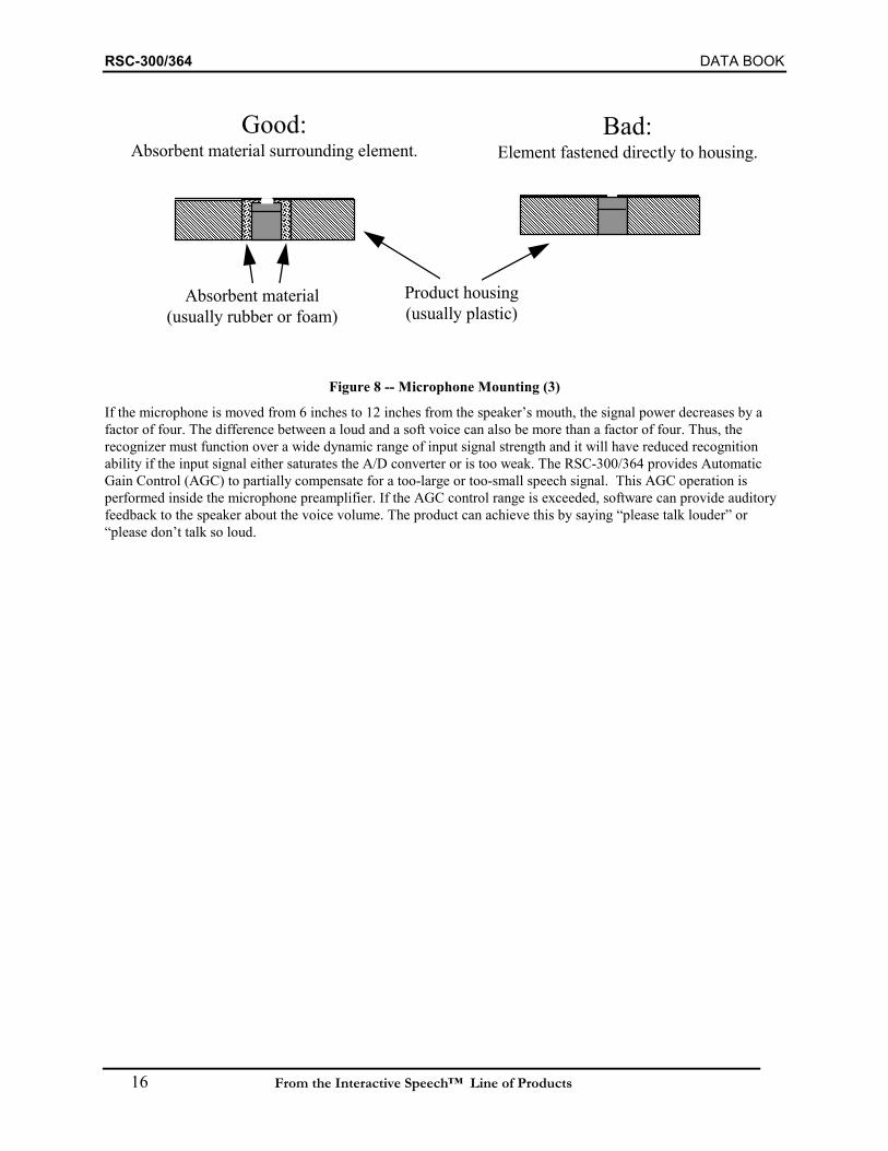
RSC-300/364 DATA BOOK
16 From the Interactive Speech™ Line of Products
Good:Absorbent material surrounding element.
Bad:Element fastened directly to housing.
Product housing(usually plastic)
Absorbent material(usually rubber or foam)
Figure 8 -- Microphone Mounting (3)
If the microphone is moved from 6 inches to 12 inches from the speaker’s mouth, the signal power decreases by afactor of four. The difference between a loud and a soft voice can also be more than a factor of four. Thus, therecognizer must function over a wide dynamic range of input signal strength and it will have reduced recognitionability if the input signal either saturates the A/D converter or is too weak. The RSC-300/364 provides AutomaticGain Control (AGC) to partially compensate for a too-large or too-small speech signal. This AGC operation isperformed inside the microphone preamplifier. If the AGC control range is exceeded, software can provide auditoryfeedback to the speaker about the voice volume. The product can achieve this by saying “please talk louder” or“please don’t talk so loud.
DATA BOOK RSC-300/364
From the Interactive Speech™ Line of Products 17
15. POWER CONSUMPTION AND POWER SUPPLY CONSIDERATIONSIn operation, the speech recognition circuit may draw a current of around 10 mA. If the system is powered oncontinuously to listen for a given word, it will drain a button battery in a few hours, or a large alkaline battery inseveral days. Thus, if the application requires that the recognizer be on all of the time, the system should operatefrom mains power. Conversely, if the product is designed to operate from batteries, it must usually remain in the low-power “sleep” mode most of the time, until it is occasionally awakened for a few seconds to recognize a word. TheRSC-300/364 can be awakened from a button press or other I/O event, or from the countdown of the Osc2 timer. Itcannot be awakened by a speech signal applied to the microphone input.
In order to conserve battery power, the product should be designed to be activated by the user each time it isrequired to recognize a word. A well-designed program will allow a few seconds after activation before attemptingrecognition in order to allow reference voltages to stabilize. A speech prompt is a good means of providing thisdelay. Current drain is higher during speech or music synthesis because power must be delivered to the speaker.
Mains-powered supply ripple should not exceed 5 millivolts measured between the VDD and GND terminals. Whenusing mains power, regulated DC supplies will typically be required. Three-terminal voltage regulators (such as the7805) are used commonly for this purpose and will provide a minimum of 47 dB of ripple rejection. The powerdissipated by these regulators is a function of the voltage differential between the input and output terminals. Forinstance, powering a 7805 regulator at 9V and delivering 10 mAmp through it will dissipate 40 mWatts of power.

RSC-300/364 DATA BOOK
18 From the Interactive Speech™ Line of Products
16. DIE BOND PAD AND QFP PIN DESCRIPTIONS
RSC-300/364(top view of die)
119
20
36
37 5455
72
33
481
16
17 32
4964
4RSC-300/364(64-lead TQFP)
Name Die Pad QFP Pin Description I/OA[15:0] 20-27, 30-37 1-8, 11-18 External Memory Address Bus O
AIN0 5 52 Analog In, low gain. (range AGND to AVDD/2.) I
AIN1 4 51 Analog In, hi gain (8X input amplitude of AIN0, same range) I
AOFE1 72 49 Output of 1st stage of preamplifier O
AOFE2 6 53 Output of 2nd stage of preamplifier O
AOFE3 3 51 Output of 3rd stage of preamplifier O
AIFE1 71 48 Output of 1st stage of preamplifier I
AIFE2 1 49 Output of 2nd stage of preamplifier I
NC 10,11,43,44 Not Connected -
PWM0 8 55 Pulse Width Modulator Output0 O
DACOUT 2 50 Analog Output (unbuffered). O
D[7:0] 12-19 57-64 External Data Bus I/O
Vss 7,28,62 9, 39,54 Vss -
PDN 67 44 Power Down. Active high when powered down. O
P1[7:0], P0[7:0] 45-52,53-60 22-29, 30-37 General Purpose Port I/O. Pin P0.0 can act as an external interruptinput. All I/O pins can act as “wake up” inputs.
I/O
/RDC 63 40 External Code Read Strobe O
/RDD 65 42 External Data Read Strobe O
/RESET 42 21 Reset I
/TE1 or PWM1 9 56 Test Mode or Pulse Width Modulator Output1 (multiplexed) I or O
VREF 70 47 Reference Voltage = Vdd/2 or Vdd/4. Depends on software -
VDD 29,61 10,38 Supply Voltage -
/WRC 64 41 External Code Write Strobe O
/WRD 66 43 External Data Write Strobe O
/XMH 68 45 External Hi-memory enable (low active) I
/XML 69 46 External Low-memory enable (low active) I
XO1 40 19 Oscillator 1 output (high frequency) O
XI1 41 20 Oscillator 1 input I
XO2 38 NA Oscillator 2 output (32768 Hz) O
XI2 39 NA Oscillator 2 input I
Note: Substrate should be connected to VSS

DATA BOOK RSC-300/364
From the Interactive Speech™ Line of Products 19
17. DIE PAD RINGp06
p07
p10
p11
p12
p13
p14
p15
p16
p17
NC
NC
rstb
xi1
xo1
xi2
xo2
a0
54 53 52 51 50 49 48 47 46 45 44 43 42 41 40 39 38 37
p05 55 North 36 a1
p04 56 35 a2
p03 57 34 a3
p02 58 33 a4
p01 59 32 a5
p00 60 31 a6
vdd 61 30 a7
gnd 62 29 vdd
rdcb 63 West East 28 gnd
wrcb 64 27 a8
rddb 65 26 a9
wrdb 66 25 a10
pdn 67 24 a11
xmhb 68 23 a12
xmlb 69 22 a13
vref 70 21 a14
aife1 71 South 20 a15
aofe1 72
1 2 3 4 5 6 7 8 9 10 11 12 13 14 15 16 17 18 19aife2
dacout
aofe3
ain1
ain0
aofe2
GND
p0/t2/bf
p1/t1
NC
NC
d7
d6
d5
d4
d3
d2
d1
d0

RSC-300/364 DATA BOOK
20 From the Interactive Speech™ Line of Products
18. RSC-300/364 DIE BONDING PAD LOCATIONS
pitch 123.85 ( only for some pads )Note: All locations are the center of the pad.
Pad # South X (um) Y (um) Pad # East X (um) Y (um) Pad # North X (um) Y (um) Pad # West X (um) Y (um)1 AIFE2 339.05 96.15 20 A15 3268.4 370.7 37 A0 2663.35 3211.6 55 P05 101.1 2513.52 DAOUT 462.9 96.15 21 A14 3268.4 494.55 38 XO2 2533.5 3211.6 56 P04 101.1 2389.653 AOFE3 586.75 96.15 22 A13 3268.4 618.4 39 XI2 2365.45 3211.6 57 P03 101.1 2265.84 AIN1 710.6 96.15 23 A12 3268.4 742.25 40 XO1 2235.65 3211.6 58 P02 101.1 2141.955 AIN0 834.45 96.15 24 A11 3268.4 866.1 41 XI1 2105.8 3211.6 59 P01 101.1 2018.16 AOFE2 958.3 96.15 25 A10 3268.4 989.95 42 RSTB 1975.9 3211.6 60 P00 101.1 1894.257 GND 1090 96.15 26 A9 3268.4 1113.8 43 NC 1830.65 3211.6 61 VDD 101.1 1764.858 P0/BF 1312.8 96.15 27 A8 3268.4 1237.65 44 NC 1700.8 3211.6 62 GND 101.1 16359 P1/T1 1665 96.15 28 GND 3268.4 1381.95 45 P17 1556.35 3211.6 63 RDCB 101.1 1504.85
10 NC 1870 96.15 29 VDD 3268.4 1511.8 46 P16 1432.5 3211.6 64 WRCB 101.1 138111 NC 1999.5 96.15 30 A7 3268.4 1652.1 47 P15 1308.65 3211.6 65 RDDB 101.1 1257.1512 D7 2131.95 96.15 31 A6 3268.4 1775.95 48 P14 1184.8 3211.6 66 WRDB 101.1 1133.313 D6 2255.8 96.15 32 A5 3268.4 1899.8 49 P13 1060.95 3211.6 67 PDN 101.1 1009.4514 D5 2379.65 96.15 33 A4 3268.4 2023.65 50 P12 937.1 3211.6 68 XMHB 101.1 885.615 D4 2503.5 96.15 34 A3 3268.4 2147.5 51 P11 813.25 3211.6 69 XMLB 101.1 761.7516 D3 2627.35 96.15 35 A2 3268.4 2271.35 52 P10 689.4 3211.6 70 VREF 101.1 637.917 D2 2751.2 96.15 36 A1 3268.4 2395.2 53 P07 565.55 3211.6 71 AIFE1 101.1 470.0518 D1 2875.05 96.15 54 P06 441.7 3211.6 72 AOFE1 101.1 346.219 D0 2998.9 96.15
Notes:1- Die Size: 3.3695 x 3.3127 mm ( NOT including Scribe )2- Scribe: 100x100 um3- Number of Probes: 725- There is 1 power supply:VDD( #29, #61 ).6- Chip orgin is at 0.0, 0.0 mm ( Lower Left Hand Corner ).7- Pad size is 100um x 100um

DATA BOOK RSC-300/364
From the Interactive Speech™ Line of Products 21
19. ABSOLUTE MAXIMUM RATINGS Any pin to GND -0.1V to +6.5V
Operating temperature(TO) -20°C to +70°C
Soldering temperature 260°C for 10 sec
Power dissipation 1 W
Operating Conditions -20°C to +70°C;
VDD=2.4 - 5.25V
VSS=0V
WARNING: Stressing the RSC-300/364 beyond the“Absolute Maximum Ratings” may cause permanentdamage. These are stress ratings only. Operationbeyond the “Operating Conditions” is notrecommended and extended exposure beyond the“Operating Conditions” may affect device reliability.
20. D.C. CHARACTERISTICS(TO = -20°C to +70°C, VDD = 2.4V – 5.25V )
SYMBOL PARAMETER MIN TYP MAX UNITS TEST CONDITIONSVIL Input Low Voltage -0.1 0.75 V
VIH(Vcc<3.6) Input High Voltage 0.8*Vdd Vdd+0.3 V
VIH(Vcc>3.6) Input High Voltage 3.0 Vdd+0.3 V
VOL Output Low Voltage 0.3 0.1*Vdd V IOL= 2 mA
VOH Output High Voltage (I/O Pins) 0.8*Vdd 0.9*Vdd V IOL= -2 mA
IIL Logical 0 Input Current <1 10 uA Vss<Vpin<Vdd
IDD1(Vcc=3.3V)
Supply Current, Active 10 20 mA Hi-Z Outputs
IDD3(Vcc=3.3V)
Supply Current, Powerdown 1 10 uA Hi-Z Outputs
Rpu Pull-up resistance P0.0-P1.7
I/O Pins
/XML,/XMH
5,80,Hi-Z
4.5,200,Hi-Z
200
kΩ
kΩ
Selected with software
Fixed
21. VDD vs. IDDIdd vs Vdd (T=25C)
05
1015202530
0 2 4 6
Vdd (v)
Idd(
mA
)
Idd(synth)
Idd(recog)
Vcc Idd(synth) Idd(recog)(No Load)
2.4 5.7 7.22.7 7.4 8.9
3 9.2 10.74 16.3 185 25.6 27.3
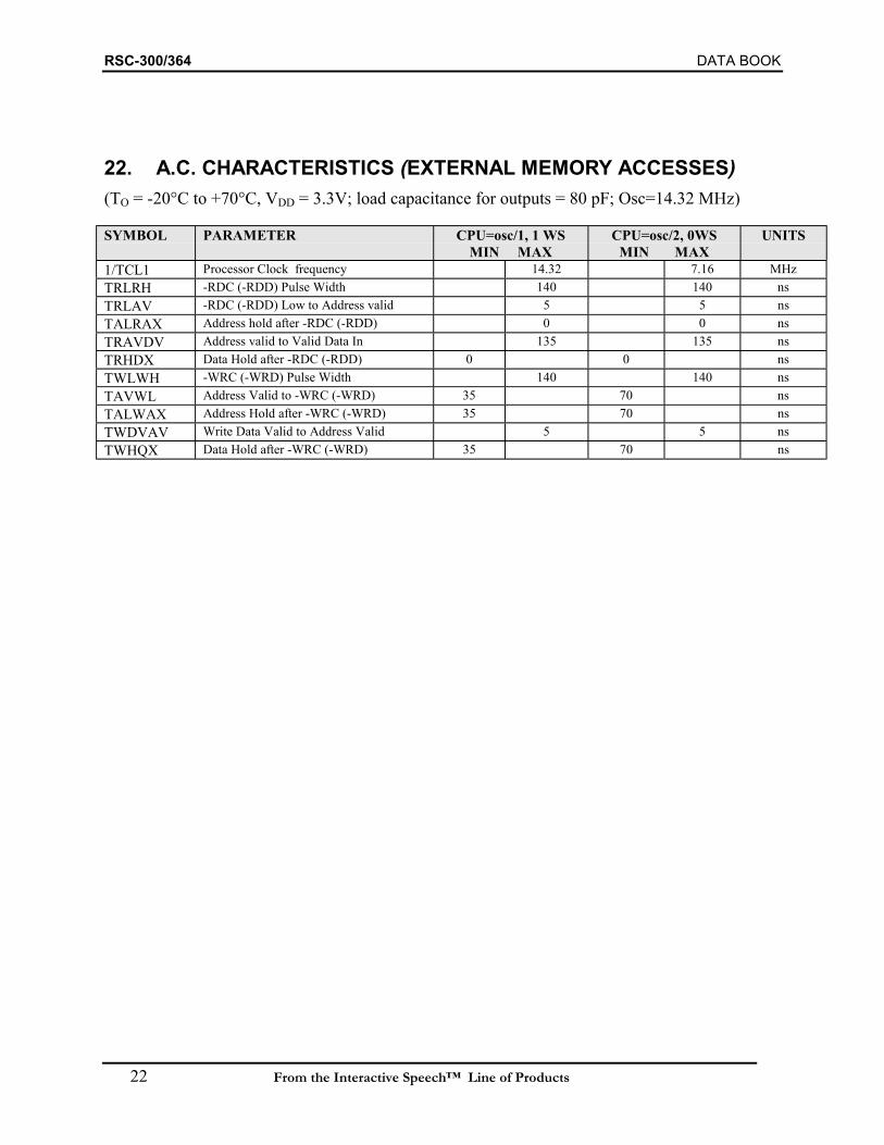
RSC-300/364 DATA BOOK
22 From the Interactive Speech™ Line of Products
22. A.C. CHARACTERISTICS (EXTERNAL MEMORY ACCESSES)(TO = -20°C to +70°C, VDD = 3.3V; load capacitance for outputs = 80 pF; Osc=14.32 MHz)
SYMBOL PARAMETER CPU=osc/1, 1 WSMIN MAX
CPU=osc/2, 0WSMIN MAX
UNITS
1/TCL1 Processor Clock frequency 14.32 7.16 MHzTRLRH -RDC (-RDD) Pulse Width 140 140 nsTRLAV -RDC (-RDD) Low to Address valid 5 5 nsTALRAX Address hold after -RDC (-RDD) 0 0 nsTRAVDV Address valid to Valid Data In 135 135 nsTRHDX Data Hold after -RDC (-RDD) 0 0 nsTWLWH -WRC (-WRD) Pulse Width 140 140 nsTAVWL Address Valid to -WRC (-WRD) 35 70 nsTALWAX Address Hold after -WRC (-WRD) 35 70 nsTWDVAV Write Data Valid to Address Valid 5 5 nsTWHQX Data Hold after -WRC (-WRD) 35 70 ns

DATA BOOK RSC-300/364
From the Interactive Speech™ Line of Products 23
23. TIMING DIAGRAMSNote that the -RDC signal does not necessarily pulse for every read from code space, but may stay low for multiplecycles.
ADDRESS
-RDD (-RDC)
DATA
-WRC (-WRD)TRLRH
TRLAV
TRAVDVTRHDX
TWLWH
ADDRESS
TAVWLTALRAX TALWAX
TWDVAVTWHQX
DATA
External Read Timing External Write Timing
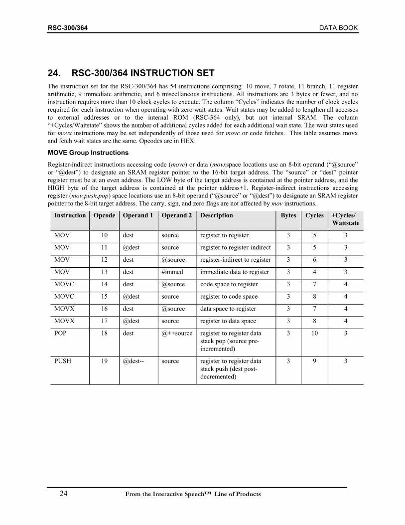
RSC-300/364 DATA BOOK
24 From the Interactive Speech™ Line of Products
24. RSC-300/364 INSTRUCTION SETThe instruction set for the RSC-300/364 has 54 instructions comprising 10 move, 7 rotate, 11 branch, 11 registerarithmetic, 9 immediate arithmetic, and 6 miscellaneous instructions. All instructions are 3 bytes or fewer, and noinstruction requires more than 10 clock cycles to execute. The column “Cycles” indicates the number of clock cyclesrequired for each instruction when operating with zero wait states. Wait states may be added to lengthen all accessesto external addresses or to the internal ROM (RSC-364 only), but not internal SRAM. The column“+Cycles/Waitstate” shows the number of additional cycles added for each additional wait state. The wait states usedfor movx instructions may be set independently of those used for movc or code fetches. This table assumes movxand fetch wait states are the same. Opcodes are in HEX.
MOVE Group InstructionsRegister-indirect instructions accessing code (movc) or data (movxspace locations use an 8-bit operand (“@source”or “@dest”) to designate an SRAM register pointer to the 16-bit target address. The “source” or “dest” pointerregister must be at an even address. The LOW byte of the target address is contained at the pointer address, and theHIGH byte of the target address is contained at the pointer address+1. Register-indirect instructions accessingregister (mov,push,pop) space locations use an 8-bit operand (“@source” or “@dest”) to designate an SRAM registerpointer to the 8-bit target address. The carry, sign, and zero flags are not affected by mov instructions.
Instruction Opcode Operand 1 Operand 2 Description Bytes Cycles +Cycles/Waitstate
MOV 10 dest source register to register 3 5 3
MOV 11 @dest source register to register-indirect 3 5 3
MOV 12 dest @source register-indirect to register 3 6 3
MOV 13 dest #immed immediate data to register 3 4 3
MOVC 14 dest @source code space to register 3 7 4
MOVC 15 @dest source register to code space 3 8 4
MOVX 16 dest @source data space to register 3 7 4
MOVX 17 @dest source register to data space 3 8 4
POP 18 dest @++source register to register datastack pop (source pre-incremented)
3 10 3
PUSH 19 @dest-- source register to register datastack push (dest post-decremented)
3 9 3
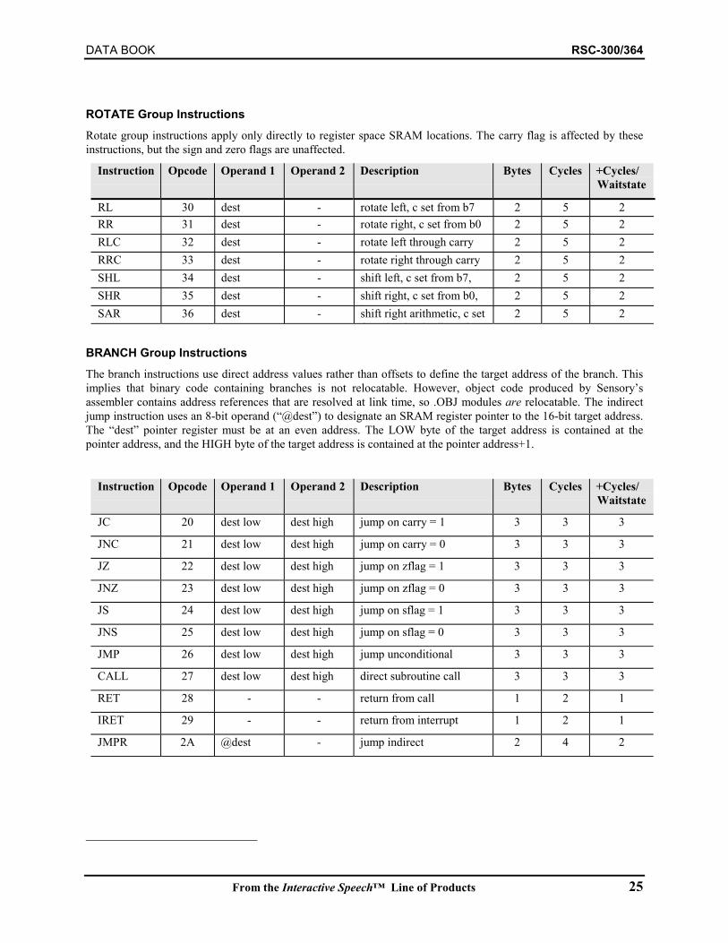
DATA BOOK RSC-300/364
From the Interactive Speech™ Line of Products 25
ROTATE Group InstructionsRotate group instructions apply only directly to register space SRAM locations. The carry flag is affected by theseinstructions, but the sign and zero flags are unaffected.
Instruction Opcode Operand 1 Operand 2 Description Bytes Cycles +Cycles/Waitstate
RL 30 dest - rotate left, c set from b7 2 5 2RR 31 dest - rotate right, c set from b0 2 5 2RLC 32 dest - rotate left through carry 2 5 2RRC 33 dest - rotate right through carry 2 5 2SHL 34 dest - shift left, c set from b7,
b2 5 2
SHR 35 dest - shift right, c set from b0,b
2 5 2SAR 36 dest - shift right arithmetic, c set
f b b d li d2 5 2
BRANCH Group InstructionsThe branch instructions use direct address values rather than offsets to define the target address of the branch. Thisimplies that binary code containing branches is not relocatable. However, object code produced by Sensory’sassembler contains address references that are resolved at link time, so .OBJ modules are relocatable. The indirectjump instruction uses an 8-bit operand (“@dest”) to designate an SRAM register pointer to the 16-bit target address.The “dest” pointer register must be at an even address. The LOW byte of the target address is contained at thepointer address, and the HIGH byte of the target address is contained at the pointer address+1.
Instruction Opcode Operand 1 Operand 2 Description Bytes Cycles +Cycles/Waitstate
JC 20 dest low dest high jump on carry = 1 3 3 3
JNC 21 dest low dest high jump on carry = 0 3 3 3
JZ 22 dest low dest high jump on zflag = 1 3 3 3
JNZ 23 dest low dest high jump on zflag = 0 3 3 3
JS 24 dest low dest high jump on sflag = 1 3 3 3
JNS 25 dest low dest high jump on sflag = 0 3 3 3
JMP 26 dest low dest high jump unconditional 3 3 3
CALL 27 dest low dest high direct subroutine call 3 3 3
RET 28 - - return from call 1 2 1
IRET 29 - - return from interrupt 1 2 1
JMPR 2A @dest - jump indirect 2 4 2

RSC-300/364 DATA BOOK
26 From the Interactive Speech™ Line of Products
MISCELLANEOUS Group Instructions
Instruction Opcode Operand 1 Operand 2 Description Bytes Cycles +Cycles/Waitstate
NOP 00 - - no operation 1 2 1
CLC 01 - - clear carry 1 2 1
STC 02 - - set carry 1 2 1
CMC 03 - - complement carry 1 2 1
CLI 04 - - disable interrupts 1 2 1
STI 05 - - enable interrupts 1 2 1
ARITHMETIC/LOGICAL Group InstructionsArithmetic and logical group instructions apply only to register space SRAM locations. The results of the instructionare always written directly to the SRAM “dest” register. All but the INCrement and DECrement instructions haveboth register source and immediate source forms.
In each of the following instructions the sign and zero flags are updated based on the result of the operation. Thecarry flag is updated by the arithmetic operations (ADD, ADC, SUB, SUBC, CP, INC, DEC) but it is not affected bythe logical operations (AND, TM, OR, XOR). Note: the carry is set high by SUB, CP, SUBC, DEC when a borrowis generated.
Instruction Opcode
Operand1
Operand2
Description Bytes Cycles +Cycles/Waitstate
AND 40 dest source logical and 3 6 3TM 41 dest source like AND, destination unchanged 3 6 3OR 42 dest source logical or 3 6 3XOR 43 dest source exclusive or 3 6 3SUB 44 dest source subtract 3 6 3CP 45 dest source like SUB, destination unchanged 3 6 3SUBC 46 dest source subtract w/carry 3 6 3ADD 47 dest source add 3 6 3ADC 48 dest source add w/carry 3 6 3INC 49 dest - increment 2 5 2DEC 4A dest - decrement 2 5 2AND 50 dest #immed logical and 3 5 3TM 51 dest #immed like AND, destination unchanged 3 5 3OR 52 dest #immed logical or 3 5 3XOR 53 dest #immed exclusive or 3 5 3SUB 54 dest #immed subtract 3 5 3CP 55 dest #immed like SUB, destination unchanged 3 5 3SUBC 56 dest #immed subtract w/carry 3 5 3ADD 57 dest #immed add 3 5 3ADC 58 dest #immed add w/carry 3 5 3

DATA BOOK RSC-300/364
From the Interactive Speech™ Line of Products 27
25. RSC-300/364 SPECIAL FUNCTION REGISTER (SFR) SUMMARYThis section describes the registers located in addresses 0E0h through 0FFh of the register space. These specialfunction registers (SFRs) are generally used for configuration control and system level functions. In many cases anapplications programmer might need to access these registers only to initialize the ports. Since the SFRs areextensively used by Sensory’s library functions, thorough understanding is essential before changing the contents ofthese registers. Some registers in this address range are for the exclusive use of Sensory Technology functions andare not further described..
The Symbol shown is the name recognized by the assembler for the associated register.
Symbol Address Register Name Type See PageP0OUT 0E0h Port 0 Output Register R/W 28P1OUT 0E1h Port 1 Output Register R/W 28
P0IN 0E2h Port 0 Input Register Read 29P1IN 0E3h Port 1 Input Register Read 29
P0CTLA 0E4h Port 0 Control Register A R/W 30P1CTLA 0E5h Port 1 Control Register A R/W 31P0CTLB 0E6h Port 0 Control Register B R/W 30P1CTLB 0E7h Port 1 Control Register B R/W 31CKCTL 0E8h Clock Control Register R/W 32WAKE0 0E9h Wakeup configuration, Port 0 R/W 33WAKE1 0EAh Wakeup configuration, Port 1 R/W 33
T1R 0EBh Timer 1 Reload R/W 34T1V 0ECh Timer 1 Counter R/W 34T2R 0EDh Timer 2 Reload R/W 35T2V 0EEh Timer 2 Counter R/W 35
ANCTL 0EFh Analog Control Register R/W 36STKPTRS 0F6h Stack Read and Write Pointers R/W 38OSC1EXT 0F7h Oscillator 1 Extended Functions R/W 39
BRKLO 0F8h Break Address Low Byte R/W 40BRKHI 0F9h Break Address High Byte R/W 40
DAC 0FAh DAC Hold Register R/W 41BANK 0FCh RAM Bank Select Register R/W 42IMR 0FDh Interrupt Mask Register R/W 43IRQ 0FEh Interrupt Request Register R/W 43
FLAGS 0FFh Flags Register R/W 44
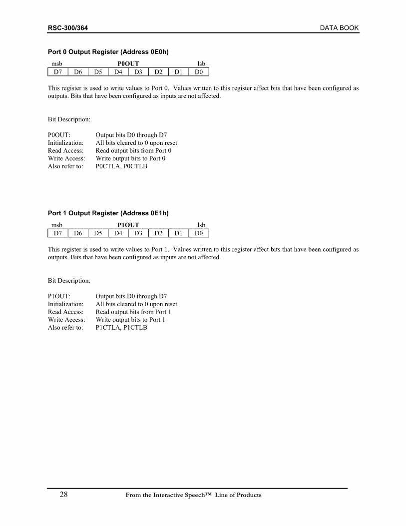
RSC-300/364 DATA BOOK
28 From the Interactive Speech™ Line of Products
Port 0 Output Register (Address 0E0h)msb P0OUT lsbD7 D6 D5 D4 D3 D2 D1 D0
This register is used to write values to Port 0. Values written to this register affect bits that have been configured asoutputs. Bits that have been configured as inputs are not affected.
Bit Description:
P0OUT: Output bits D0 through D7Initialization: All bits cleared to 0 upon resetRead Access: Read output bits from Port 0Write Access: Write output bits to Port 0Also refer to: P0CTLA, P0CTLB
Port 1 Output Register (Address 0E1h)msb P1OUT lsbD7 D6 D5 D4 D3 D2 D1 D0
This register is used to write values to Port 1. Values written to this register affect bits that have been configured asoutputs. Bits that have been configured as inputs are not affected.
Bit Description:
P1OUT: Output bits D0 through D7Initialization: All bits cleared to 0 upon resetRead Access: Read output bits from Port 1Write Access: Write output bits to Port 1Also refer to: P1CTLA, P1CTLB
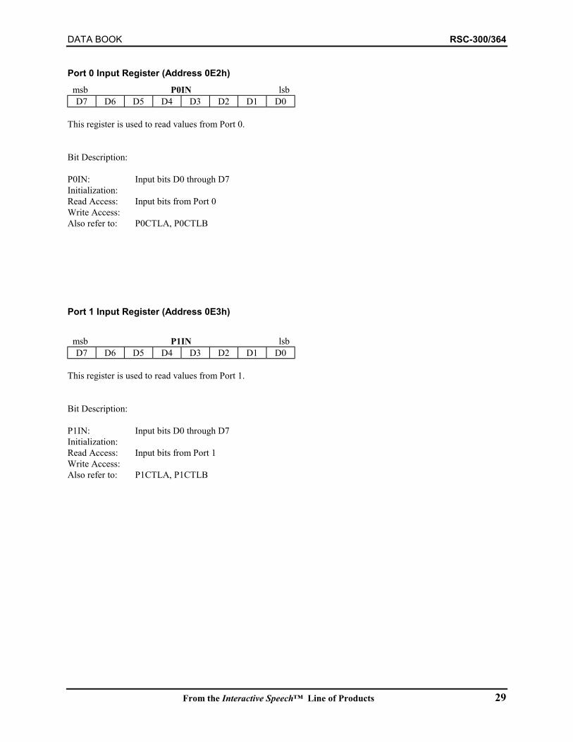
DATA BOOK RSC-300/364
From the Interactive Speech™ Line of Products 29
Port 0 Input Register (Address 0E2h)msb P0IN lsbD7 D6 D5 D4 D3 D2 D1 D0
This register is used to read values from Port 0.
Bit Description:
P0IN: Input bits D0 through D7Initialization:Read Access: Input bits from Port 0Write Access:Also refer to: P0CTLA, P0CTLB
Port 1 Input Register (Address 0E3h)
msb P1IN lsbD7 D6 D5 D4 D3 D2 D1 D0
This register is used to read values from Port 1.
Bit Description:
P1IN: Input bits D0 through D7Initialization:Read Access: Input bits from Port 1Write Access:Also refer to: P1CTLA, P1CTLB
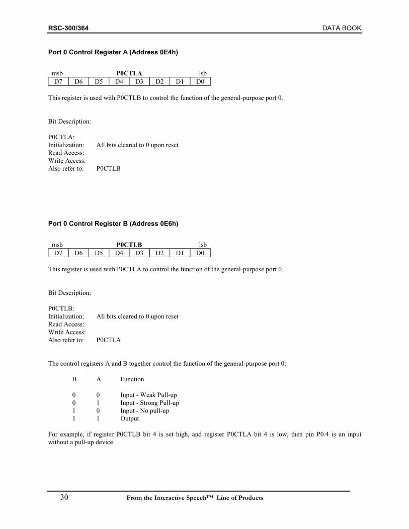
RSC-300/364 DATA BOOK
30 From the Interactive Speech™ Line of Products
Port 0 Control Register A (Address 0E4h)
msb P0CTLA lsbD7 D6 D5 D4 D3 D2 D1 D0
This register is used with P0CTLB to control the function of the general-purpose port 0.
Bit Description:
P0CTLA:Initialization: All bits cleared to 0 upon resetRead Access:Write Access:Also refer to: P0CTLB
Port 0 Control Register B (Address 0E6h)
msb P0CTLB lsbD7 D6 D5 D4 D3 D2 D1 D0
This register is used with P0CTLA to control the function of the general-purpose port 0.
Bit Description:
P0CTLB:Initialization: All bits cleared to 0 upon resetRead Access:Write Access:Also refer to: P0CTLA
The control registers A and B together control the function of the general-purpose port 0:
B A Function
0 0 Input - Weak Pull-up0 1 Input - Strong Pull-up1 0 Input - No pull-up1 1 Output
For example, if register P0CTLB bit 4 is set high, and register P0CTLA bit 4 is low, then pin P0.4 is an inputwithout a pull-up device.

DATA BOOK RSC-300/364
From the Interactive Speech™ Line of Products 31
Port 1 Control Register A (Address 0E5h)
msb P1CTLA lsbD7 D6 D5 D4 D3 D2 D1 D0
This register is used with P1CTLB to control the function of the general-purpose port 1.
Bit Description:
P1CTLA:Initialization: All bits cleared to 0 upon resetRead Access:Write Access:Also refer to: P1CTLB
Port 1 Control Register B (Address 0E7h)
msb P1CTLB lsbD7 D6 D5 D4 D3 D2 D1 D0
This register is used with P1CTLA to control the function of the general-purpose port 1.
Bit Description:
P1CTLB:Initialization: All bits cleared to 0 upon resetRead Access:Write Access:Also refer to: P1CTLA
The control registers A and B together control the function of the general-purpose port 1:
B A Function
0 0 Input - Weak Pull-up0 1 Input - Strong Pull-up1 0 Input - No pull-up1 1 Output
For example, if register P1CTLB bit 3 is cleared, and register P1CTLA bit 3 is set high, then pin P1.3 is an inputwith a strong pull-up.

RSC-300/364 DATA BOOK
32 From the Interactive Speech™ Line of Products
Clock Control Register (Address 0E8h)
msb CKCTL lsbPD T2 FC CD1 CD0 PCS DO2 EO1
This register is used to enable the two oscillators, to select the processor clock source and the internal clock divider,and to enable some sleep/wakeup functions. Sensory’s library code may initialize specific settings for this register,so it should be changed only with care.
Bit Description:
CKCTL.0: EO10: Enable Oscillator #1 inverter
1: Disable Oscillator #1Cleared by reset or (wakeup & (PCS=0) )
CKCTL.1: DO20: Disable Oscillator #2 inverter1: Enable Oscillator #2 inverterCleared by reset.
CKCTL.2: PCS0: Processor clock source = Oscillator 11: Processor clock source = Oscillator 2Cleared by reset.
CKCTL.4-CKCTL.3: CD1-CD0Select processor clock divisor. The processor clock rate is the fraction of the source clock shown.
CD1 CD0 Division0 0 1/20 1 1/11 0 1/81 1 1/256
Cleared by reset.
CKCTL.5: FC0: Disable reserved function clock1: Enable reserved function clockCleared by reset.
CKCTL 6: T20: Timer #2 overflow does not cause wakeup1: Timer #2 overflow causes wakeupCleared by reset.
CKCTL.7: PD0: Processor is in operational state1: Processor is in PowerDown state (“sleep”)Cleared by reset and wakeup.

DATA BOOK RSC-300/364
From the Interactive Speech™ Line of Products 33
Port 0 Wakeup Configuration Register (Address 0E9h)
msb WAKE0 lsbD7 D6 D5 D4 D3 D2 D1 D0
The Wake0 register controls the enabling of I/O events on port0 that can cause a processor “wakeup”. These wakeupevents are recognized independently of whether the processor is running or stopped. The processor may also bewaked up by countdown of Timer2. For a general description, see Power Down and Wakeup Operation, page 10.
Bit Description:
WAKE0.7-WAKE0.0 Wake Enable0: Wakeup is not enabled on corresponding P0 port bit1: Wakeup is ENABLED on corresponding P0 port bit
Each bit, if set, enables the corresponding general purpose I/O pin of ports P0.0-P0.7 to generate a wake-up event.If enabled, the polarity of the wake-up trigger is determined by the corresponding bit in the output register: if theinput matches the output register, a wake-up even is generated. It is assumed that the general-purpose pin isconfigured to be an input.
Each bit, if clear, prevents the corresponding general-purpose I/O pin of ports P0.0-P0.7 from generating a wake-upevent.
Initialization: All bits cleared to 0 upon resetAlso refer to: WAKE1, P0IN, P0CTLA, P0CTLB
Port 1 Wakeup Configuration Register (Address 0EAh)
msb WAKE1 lsbD7 D6 D5 D4 D3 D2 D1 D0
The Wake1 register controls the enabling of I/O events on port1 that can cause a processor “wakeup”. Thesewakeup events are recognized independently of whether the processor is running or stopped. For a generaldescription, see Power Down and Wakeup Operation, page 10.
Bit Description:
WAKE1.7-WAKE1.0 Wake Enable0: Wakeup is not enabled on corresponding P1 port bit1: Wakeup is ENABLED on corresponding P1 port bit
Each bit, if set, enables the corresponding general-purpose I/O pin of ports P1.0-P1.7 to generate a wake-up event.If enabled, the polarity of the wake-up trigger is determined by the corresponding bit in the output register: if theinput matches the output register, a wake-up even is generated. It is assumed that the general-purpose pin isconfigured to be an input.
Each bit, if clear, prevents the corresponding general purpose I/O pin of ports P1.0-P1.7 from generating a wake-upevent.
Initialization: All bits cleared to 0 upon resetAlso refer to: WAKE0, P1IN, P1CTLA, P1CTLB
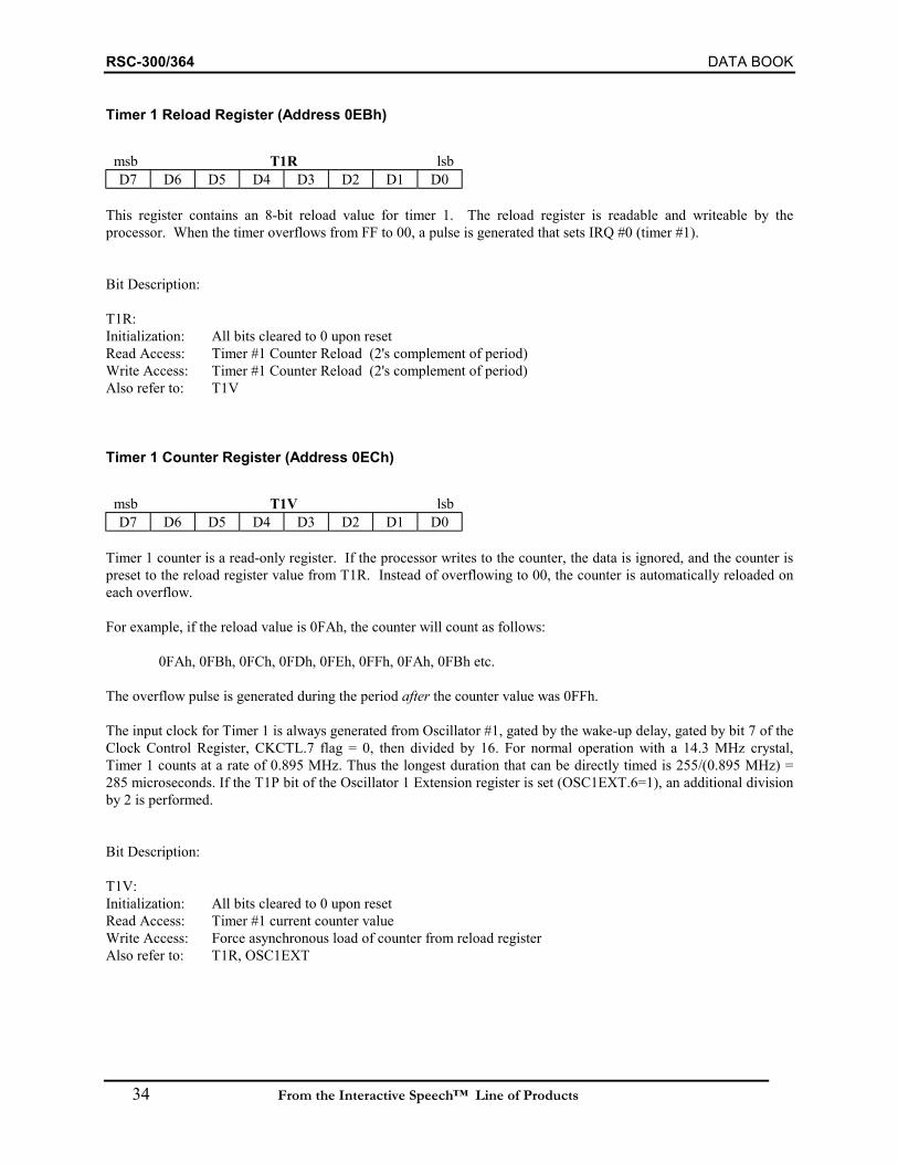
RSC-300/364 DATA BOOK
34 From the Interactive Speech™ Line of Products
Timer 1 Reload Register (Address 0EBh)
msb T1R lsbD7 D6 D5 D4 D3 D2 D1 D0
This register contains an 8-bit reload value for timer 1. The reload register is readable and writeable by theprocessor. When the timer overflows from FF to 00, a pulse is generated that sets IRQ #0 (timer #1).
Bit Description:
T1R:Initialization: All bits cleared to 0 upon resetRead Access: Timer #1 Counter Reload (2's complement of period)Write Access: Timer #1 Counter Reload (2's complement of period)Also refer to: T1V
Timer 1 Counter Register (Address 0ECh)
msb T1V lsbD7 D6 D5 D4 D3 D2 D1 D0
Timer 1 counter is a read-only register. If the processor writes to the counter, the data is ignored, and the counter ispreset to the reload register value from T1R. Instead of overflowing to 00, the counter is automatically reloaded oneach overflow.
For example, if the reload value is 0FAh, the counter will count as follows:
0FAh, 0FBh, 0FCh, 0FDh, 0FEh, 0FFh, 0FAh, 0FBh etc.
The overflow pulse is generated during the period after the counter value was 0FFh.
The input clock for Timer 1 is always generated from Oscillator #1, gated by the wake-up delay, gated by bit 7 of theClock Control Register, CKCTL.7 flag = 0, then divided by 16. For normal operation with a 14.3 MHz crystal,Timer 1 counts at a rate of 0.895 MHz. Thus the longest duration that can be directly timed is 255/(0.895 MHz) =285 microseconds. If the T1P bit of the Oscillator 1 Extension register is set (OSC1EXT.6=1), an additional divisionby 2 is performed.
Bit Description:
T1V:Initialization: All bits cleared to 0 upon resetRead Access: Timer #1 current counter valueWrite Access: Force asynchronous load of counter from reload registerAlso refer to: T1R, OSC1EXT
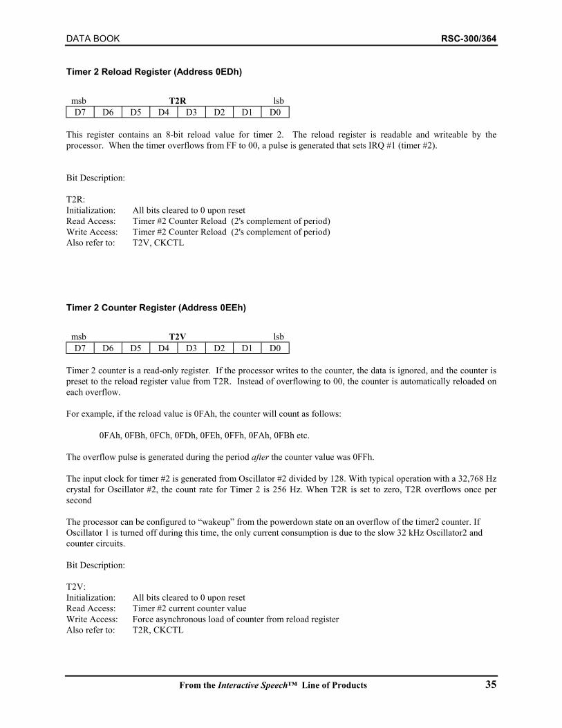
DATA BOOK RSC-300/364
From the Interactive Speech™ Line of Products 35
Timer 2 Reload Register (Address 0EDh)
msb T2R lsbD7 D6 D5 D4 D3 D2 D1 D0
This register contains an 8-bit reload value for timer 2. The reload register is readable and writeable by theprocessor. When the timer overflows from FF to 00, a pulse is generated that sets IRQ #1 (timer #2).
Bit Description:
T2R:Initialization: All bits cleared to 0 upon resetRead Access: Timer #2 Counter Reload (2's complement of period)Write Access: Timer #2 Counter Reload (2's complement of period)Also refer to: T2V, CKCTL
Timer 2 Counter Register (Address 0EEh)
msb T2V lsbD7 D6 D5 D4 D3 D2 D1 D0
Timer 2 counter is a read-only register. If the processor writes to the counter, the data is ignored, and the counter ispreset to the reload register value from T2R. Instead of overflowing to 00, the counter is automatically reloaded oneach overflow.
For example, if the reload value is 0FAh, the counter will count as follows:
0FAh, 0FBh, 0FCh, 0FDh, 0FEh, 0FFh, 0FAh, 0FBh etc.
The overflow pulse is generated during the period after the counter value was 0FFh.
The input clock for timer #2 is generated from Oscillator #2 divided by 128. With typical operation with a 32,768 Hzcrystal for Oscillator #2, the count rate for Timer 2 is 256 Hz. When T2R is set to zero, T2R overflows once persecond
The processor can be configured to “wakeup” from the powerdown state on an overflow of the timer2 counter. IfOscillator 1 is turned off during this time, the only current consumption is due to the slow 32 kHz Oscillator2 andcounter circuits.
Bit Description:
T2V:Initialization: All bits cleared to 0 upon resetRead Access: Timer #2 current counter valueWrite Access: Force asynchronous load of counter from reload registerAlso refer to: T2R, CKCTL
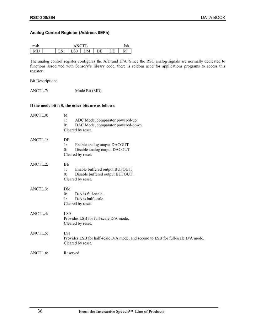
RSC-300/364 DATA BOOK
36 From the Interactive Speech™ Line of Products
Analog Control Register (Address 0EFh)
msb ANCTL lsbMD LS1 LS0 DM BE DE M
The analog control register configures the A/D and D/A. Since the RSC analog signals are normally dedicated tofunctions associated with Sensory’s library code, there is seldom need for applications programs to access thisregister.
Bit Description:
ANCTL.7: Mode Bit (MD)
If the mode bit is 0, the other bits are as follows:
ANCTL.0: M1: ADC Mode, comparator powered-up.0: DAC Mode, comparator powered-down.Cleared by reset.
ANCTL.1: DE1: Enable analog output DACOUT0: Disable analog output DACOUTCleared by reset.
ANCTL.2: BE1: Enable buffered output BUFOUT.0: Disable buffered output BUFOUT.Cleared by reset.
ANCTL.3: DM0: D/A is full-scale.1: D/A is half-scale.Cleared by reset.
ANCTL.4: LS0Provides LSB for full-scale D/A mode.Cleared by reset.
ANCTL.5: LS1Provides LSB for half-scale D/A mode, and second to LSB for full-scale D/A mode.Cleared by reset.
ANCTL.6: Reserved

DATA BOOK RSC-300/364
From the Interactive Speech™ Line of Products 37
Analog Control Register (Address 0EFh) (continued)
If the mode bit is 1, the other bits are as follows:
ANCTL.0-ANCTL.1: Control the inverter strength of the 32,768 Hz oscillatorBit 1 Bit 0 Strength
0 0 5 µA 0 1 10 µA 1 0 20 µA 1 1 40 µA
ANCTL.2-ANCTL.3: Control the output resistor of the 32,768 Hz oscillatorBit 3 Bit 2 Resistance
0 0 50 KΩ 0 1 100 KΩ 1 0 200 KΩ 1 1 400 KΩ
ANCTL.4-ANCTL.6: Reserved
When reading from the Analog Control Register, the side containing the 32,768 Hz oscillator control parameters isnot read, while the other side is read.
Read Access:Write Access:Initialization: On reset, both sides of the Analog Control Register are set to zero.Also refer to:
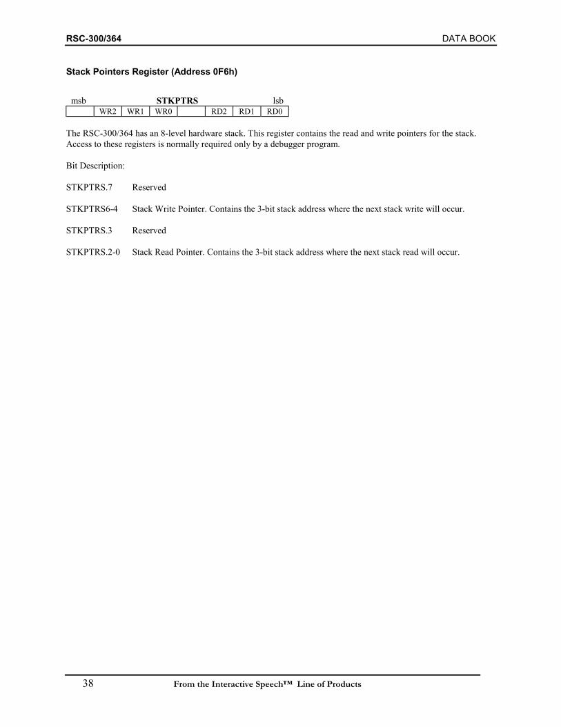
RSC-300/364 DATA BOOK
38 From the Interactive Speech™ Line of Products
Stack Pointers Register (Address 0F6h)
msb STKPTRS lsbWR2 WR1 WR0 RD2 RD1 RD0
The RSC-300/364 has an 8-level hardware stack. This register contains the read and write pointers for the stack.Access to these registers is normally required only by a debugger program.
Bit Description:
STKPTRS.7 Reserved
STKPTRS6-4 Stack Write Pointer. Contains the 3-bit stack address where the next stack write will occur.
STKPTRS.3 Reserved
STKPTRS.2-0 Stack Read Pointer. Contains the 3-bit stack address where the next stack read will occur.

DATA BOOK RSC-300/364
From the Interactive Speech™ Line of Products 39
Oscillator1 Extension Register (Address 0F7h)
msb OSC1EXT lsbIRW T1P MX WX4 WX3 WX2 WX1 WX0
This register controls a variety of extended use options for prescalers and extra wait states derived from Oscillator 1.
Bit Description:
OSC1EXT[4:0] WX4-WX0 Control the number of wait states inserted for movx instructions whenOSC1EXT.5=1. This allows simplified operation with slow external read/writememories. If no wait states are used, movx access duration is one clock.Controlled program delays in the microsecond range can be obtained by settingthe desired number of wait states and executing a dummy movx.
0 0 0 0 0 Use zero additional wait states (70 nsec at 14.3 MHz)1 1 1 1 1 Use 31 additional wait states (2.24 µsec at 14.3 MHz).
OSC1EXT.5 MX0: movx instructions use wait states in BANK[7:5]1: movx instructions use wait states in OSC1EXT[4:0]Cleared by reset.
OSC1EXT.6 T1P0: Timer1 Prescaler uses Osc11: Timer1 Prescaler uses Osc1/2Cleared by reset.
OSC1EXT.7: IRZ0: Internal ROM (RSC-364 only) accesses use wait states in Reg BANK[7:5]1: Internal ROM (RSC-364 only) accesses use zero wait statesCleared by reset.
Also refer to: CKCTL, BANK

RSC-300/364 DATA BOOK
40 From the Interactive Speech™ Line of Products
Break Address Low Register (Address 0F8h)
msb BRKLO lsbA7 A6 A5 A4 A3 A2 A1 A0
This register contains the low 8-bits of the 16-bit Break Address. The high 8-bits of the Break Address are held inthe Break Address High register. These registers may be read or written only when the trap bit is set (See page 44).When the trap bit is set, each pending PC address is compared with the breakpoint address. When a match occurs,then the PC does not fetch the instruction at the breakpoint address, but rather performs a trap. When a trap isperformed the flags register is saved, timers are stopped, interrupts are disabled, and execution branches to location0FFF8h.
Bit Description:BRKLO.7-0 Break Address Low bits [7:0]
Set to 0FFh by reset.
Also refer to: BRKHI, FLAGS
Break Address High Register (Address 0F9h)
msb BRKHI lsbA15 A14 A13 A12 A11 A10 A9 A8
This register contains the high 8-bits of the 16-bit Break Address. The low 8-bits of the Break Address are held inthe Break Address Low register. These registers may be read or written only when the trap bit is set (See page 44).When the trap bit is set, each pending PC address is compared with the breakpoint address. When a match occurs,then the PC does not fetch the instruction at the breakpoint address, but rather performs a trap. When a trap isperformed the flags register is saved, timers are stopped, interrupts are disabled, and execution branches to location0FFF8h.
Bit Description:BRKHI.7-0 Break Address High bits [15:8]
Set to 0FFh by reset.
Also refer to: BRKHI, FLAGS
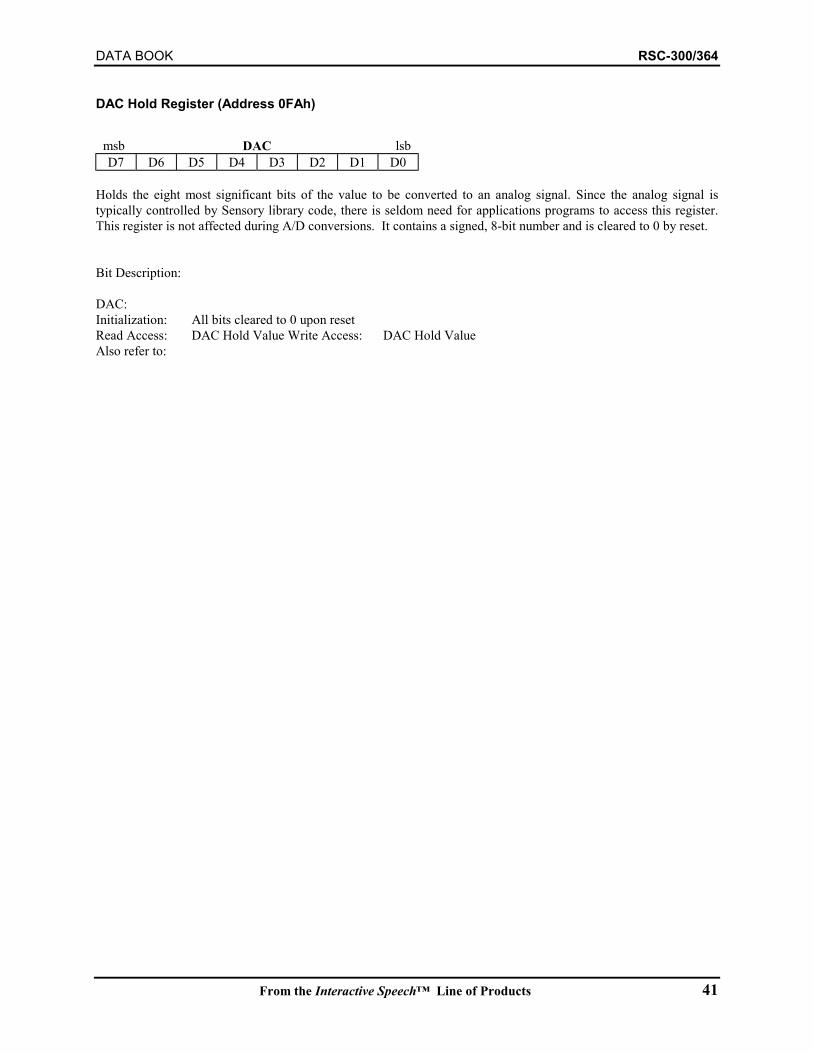
DATA BOOK RSC-300/364
From the Interactive Speech™ Line of Products 41
DAC Hold Register (Address 0FAh)
msb DAC lsbD7 D6 D5 D4 D3 D2 D1 D0
Holds the eight most significant bits of the value to be converted to an analog signal. Since the analog signal istypically controlled by Sensory library code, there is seldom need for applications programs to access this register.This register is not affected during A/D conversions. It contains a signed, 8-bit number and is cleared to 0 by reset.
Bit Description:
DAC:Initialization: All bits cleared to 0 upon resetRead Access: DAC Hold Value Write Access: DAC Hold ValueAlso refer to:
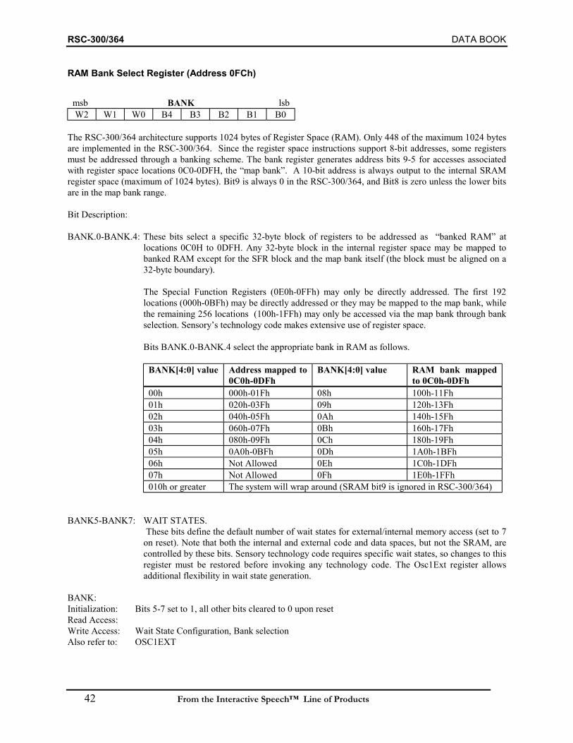
RSC-300/364 DATA BOOK
42 From the Interactive Speech™ Line of Products
RAM Bank Select Register (Address 0FCh)
msb BANK lsbW2 W1 W0 B4 B3 B2 B1 B0
The RSC-300/364 architecture supports 1024 bytes of Register Space (RAM). Only 448 of the maximum 1024 bytesare implemented in the RSC-300/364. Since the register space instructions support 8-bit addresses, some registersmust be addressed through a banking scheme. The bank register generates address bits 9-5 for accesses associatedwith register space locations 0C0-0DFH, the “map bank”. A 10-bit address is always output to the internal SRAMregister space (maximum of 1024 bytes). Bit9 is always 0 in the RSC-300/364, and Bit8 is zero unless the lower bitsare in the map bank range.
Bit Description:
BANK.0-BANK.4: These bits select a specific 32-byte block of registers to be addressed as “banked RAM” atlocations 0C0H to 0DFH. Any 32-byte block in the internal register space may be mapped tobanked RAM except for the SFR block and the map bank itself (the block must be aligned on a32-byte boundary).
The Special Function Registers (0E0h-0FFh) may only be directly addressed. The first 192locations (000h-0BFh) may be directly addressed or they may be mapped to the map bank, whilethe remaining 256 locations (100h-1FFh) may only be accessed via the map bank through bankselection. Sensory’s technology code makes extensive use of register space.
Bits BANK.0-BANK.4 select the appropriate bank in RAM as follows.
BANK[4:0] value Address mapped to0C0h-0DFh
BANK[4:0] value RAM bank mappedto 0C0h-0DFh
00h 000h-01Fh 08h 100h-11Fh01h 020h-03Fh 09h 120h-13Fh02h 040h-05Fh 0Ah 140h-15Fh03h 060h-07Fh 0Bh 160h-17Fh04h 080h-09Fh 0Ch 180h-19Fh05h 0A0h-0BFh 0Dh 1A0h-1BFh06h Not Allowed 0Eh 1C0h-1DFh07h Not Allowed 0Fh 1E0h-1FFh010h or greater The system will wrap around (SRAM bit9 is ignored in RSC-300/364)
BANK5-BANK7: WAIT STATES. These bits define the default number of wait states for external/internal memory access (set to 7on reset). Note that both the internal and external code and data spaces, but not the SRAM, arecontrolled by these bits. Sensory technology code requires specific wait states, so changes to thisregister must be restored before invoking any technology code. The Osc1Ext register allowsadditional flexibility in wait state generation.
BANK:Initialization: Bits 5-7 set to 1, all other bits cleared to 0 upon resetRead Access:Write Access: Wait State Configuration, Bank selectionAlso refer to: OSC1EXT
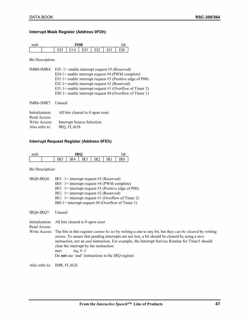
DATA BOOK RSC-300/364
From the Interactive Speech™ Line of Products 43
Interrupt Mask Register (Address 0FDh)
msb IMR lsbEI5 E14 EI3 EI2 EI1 EI0
Bit Description:
IMR0-IMR4: EI5: 1= enable interrupt request #5 (Reserved)EI4:1= enable interrupt request #4 (PWM complete)EI3:1= enable interrupt request #3 (Positive edge of P00)EI2:1= enable interrupt request #2 (Reserved)EI1:1= enable interrupt request #1 (Overflow of Timer 2)EI0:1= enable interrupt request #0 (Overflow of Timer 1)
IMR6-IMR7: Unused
Initialization: All bits cleared to 0 upon resetRead Access:Write Access: Interrupt Source SelectionAlso refer to: IRQ, FLAGS
Interrupt Request Register (Address 0FEh)
msb IRQ lsbIR5 IR4 IR3 IR2 IR1 IR0
Bit Description:
IRQ0-IRQ4: IR5: 1= interrupt request #5 (Reserved)IR4: 1= interrupt request #4 (PWM complete)IR3: 1= interrupt request #3 (Positive edge of P00)IR2: 1= interrupt request #2 (Reserved)IR1: 1= interrupt request #1 (Overflow of Timer 2)IR0:1= interrupt request #0 (Overflow of Timer 1)
IRQ6-IRQ7: Unused
Initialization: All bits cleared to 0 upon resetRead Access:Write Access: The bits in this register cannot be set by writing a one to any bit, but they can be cleared by writing
zeroes. To assure that pending interrupts are not lost, a bit should be cleared by using a movinstruction, not an and instruction. For example, the Interrupt Service Routine for Timer1 shouldclear the interrupt by the instruction:mov irq, #~1Do not use ‘and’ instructions in the IRQ register.
Also refer to: IMR, FLAGS
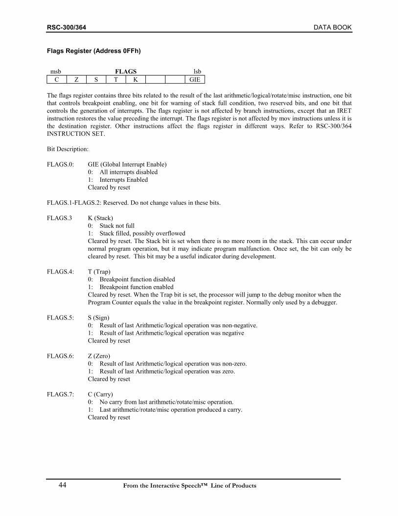
RSC-300/364 DATA BOOK
44 From the Interactive Speech™ Line of Products
Flags Register (Address 0FFh)
msb FLAGS lsbC Z S T K GIE
The flags register contains three bits related to the result of the last arithmetic/logical/rotate/misc instruction, one bitthat controls breakpoint enabling, one bit for warning of stack full condition, two reserved bits, and one bit thatcontrols the generation of interrupts. The flags register is not affected by branch instructions, except that an IRETinstruction restores the value preceding the interrupt. The flags register is not affected by mov instructions unless it isthe destination register. Other instructions affect the flags register in different ways. Refer to RSC-300/364INSTRUCTION SET.
Bit Description:
FLAGS.0: GIE (Global Interrupt Enable)0: All interrupts disabled1: Interrupts EnabledCleared by reset
FLAGS.1-FLAGS.2: Reserved. Do not change values in these bits.
FLAGS.3 K (Stack)0: Stack not full1: Stack filled, possibly overflowedCleared by reset. The Stack bit is set when there is no more room in the stack. This can occur undernormal program operation, but it may indicate program malfunction. Once set, the bit can only becleared by reset. This bit may be a useful indicator during development.
FLAGS.4: T (Trap)0: Breakpoint function disabled1: Breakpoint function enabledCleared by reset. When the Trap bit is set, the processor will jump to the debug monitor when the Program Counter equals the value in the breakpoint register. Normally only used by a debugger.
FLAGS.5: S (Sign)0: Result of last Arithmetic/logical operation was non-negative.1: Result of last Arithmetic/logical operation was negativeCleared by reset
FLAGS.6: Z (Zero)0: Result of last Arithmetic/logical operation was non-zero.1: Result of last Arithmetic/logical operation was zero.Cleared by reset
FLAGS.7: C (Carry)0: No carry from last arithmetic/rotate/misc operation.1: Last arithmetic/rotate/misc operation produced a carry.Cleared by reset

DATA BOOK RSC-300/364
From the Interactive Speech™ Line of Products 45
26. SPECIAL DATA SPACE ADDRESSES SUMMARY
As described previously, the RSC-300/364 uses movx instructions to access all Data Space locations. Typically DataSpace locations are external, but a few specific locations are mapped internally in the last page (0FF00h-0FFFFh) ofData Space. For this reason, it is generally best to plan to use no external addresses in the last page of Data Space.(The important exception to this is the debugger interface, mapped externally at 0FFFCh-0FFFFh.) The internally-mapped addresses include the Stack registers and the Pulse Width Modulator registers. The RSC-300/364 also has2 Kbytes of internal data space SRAM. This SRAM is reserved for technology functions and does not conflict withexternal SRAM.
Stack Registers (8 each of 16 bits)Occasionally it is useful to manipulate the stack directly (for example, to leave a deeply nested series of calls withoutunwinding when a fatal error is detected.). Since the RSC-300/364 stack space is limited, the need for suchmanipulations is unlikely, but the information here allows doing so if desired. The stack pointer registers aredescribed on page 38.
Address Location Name Type Notes0FFC0h Stack 0 Low byte R/W0FFC1h Stack 0 High byte R/W0FFC2h Stack 1 Low byte R/W0FFC3h Stack 1 High byte R/W0FFC4h Stack 2 Low byte R/W0FFC5h Stack 2 High byte R/W0FFC6h Stack 3 Low byte R/W0FFC7h Stack 3 High byte R/W0FFC8h Stack 4 Low byte R/W0FFC9h Stack 4 High byte R/W0FFCAh Stack 5 Low byte R/W0FFCBh Stack 5 High byte R/W0FFCCh Stack 6 Low byte R/W0FFCDh Stack 6 High byte R/WOFFCEh Stack 7 High R/W
Pulse Width Modulator (PWM) RegistersThe Pulse Width Modulator registers enable and control the operation of the PWM. When producing speech ormusic, these registers are controlled by Sensory’s technology code and should not be touched by applications.
Address Location Name Type Page0FFE0h PWMCTRL W/O 450FFE1h PWMA W/O 450FFE2h PWMDATA R/W 46
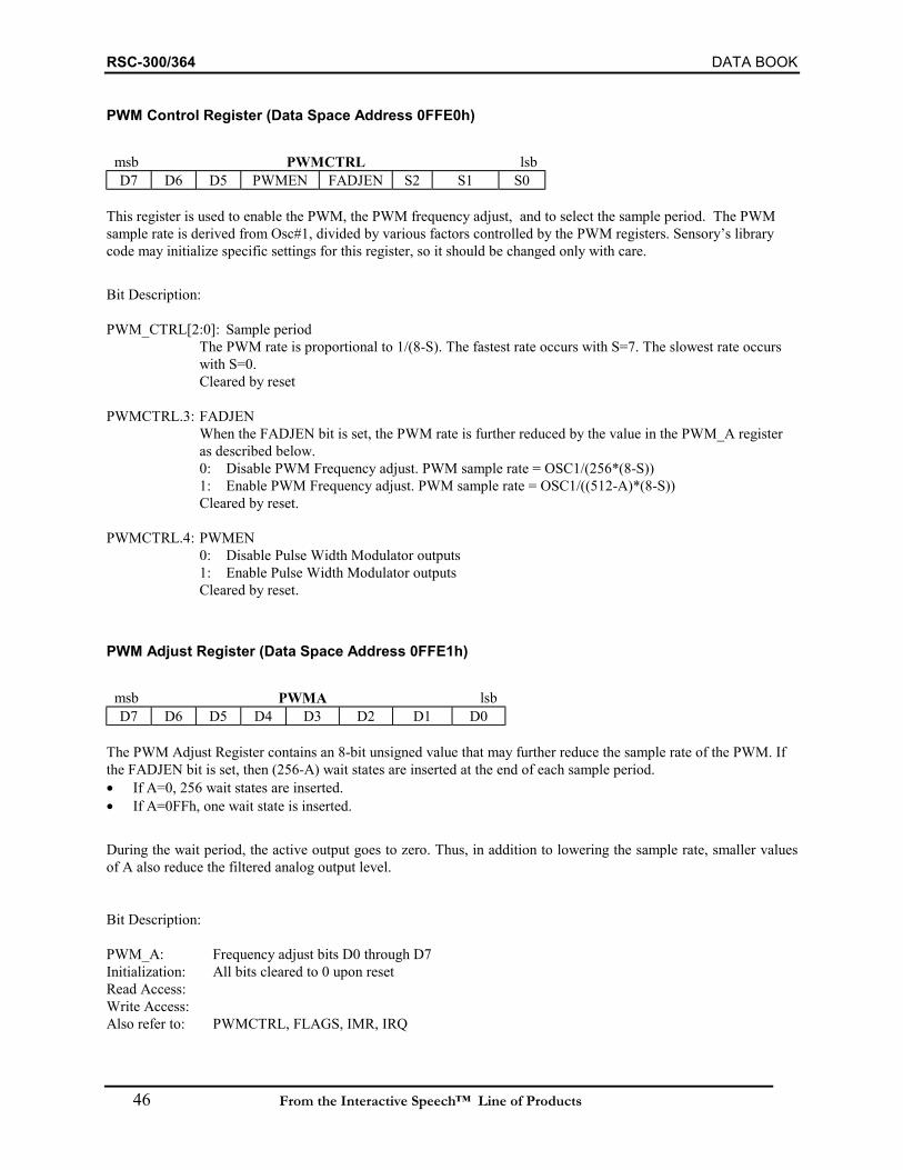
RSC-300/364 DATA BOOK
46 From the Interactive Speech™ Line of Products
PWM Control Register (Data Space Address 0FFE0h)
msb PWMCTRL lsbD7 D6 D5 PWMEN FADJEN S2 S1 S0
This register is used to enable the PWM, the PWM frequency adjust, and to select the sample period. The PWMsample rate is derived from Osc#1, divided by various factors controlled by the PWM registers. Sensory’s librarycode may initialize specific settings for this register, so it should be changed only with care.
Bit Description:
PWM_CTRL[2:0]: Sample periodThe PWM rate is proportional to 1/(8-S). The fastest rate occurs with S=7. The slowest rate occurs with S=0.Cleared by reset
PWMCTRL.3: FADJENWhen the FADJEN bit is set, the PWM rate is further reduced by the value in the PWM_A register as described below.0: Disable PWM Frequency adjust. PWM sample rate = OSC1/(256*(8-S))1: Enable PWM Frequency adjust. PWM sample rate = OSC1/((512-A)*(8-S))Cleared by reset.
PWMCTRL.4: PWMEN0: Disable Pulse Width Modulator outputs1: Enable Pulse Width Modulator outputsCleared by reset.
PWM Adjust Register (Data Space Address 0FFE1h)
msb PWMA lsbD7 D6 D5 D4 D3 D2 D1 D0
The PWM Adjust Register contains an 8-bit unsigned value that may further reduce the sample rate of the PWM. Ifthe FADJEN bit is set, then (256-A) wait states are inserted at the end of each sample period.• If A=0, 256 wait states are inserted.• If A=0FFh, one wait state is inserted.
During the wait period, the active output goes to zero. Thus, in addition to lowering the sample rate, smaller valuesof A also reduce the filtered analog output level.
Bit Description:
PWM_A: Frequency adjust bits D0 through D7Initialization: All bits cleared to 0 upon resetRead Access:Write Access:Also refer to: PWMCTRL, FLAGS, IMR, IRQ
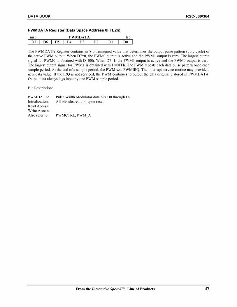
DATA BOOK RSC-300/364
From the Interactive Speech™ Line of Products 47
PWMDATA Register (Data Space Address 0FFE2h)msb PWMDATA lsbD7 D6 D5 D4 D3 D2 D1 D0
The PWMDATA Register contains an 8-bit unsigned value that determines the output pulse pattern (duty cycle) ofthe active PWM output. When D7=0, the PWM0 output is active and the PWM1 output is zero. The largest outputsignal for PWM0 is obtained with D=00h. When D7=1, the PWM1 output is active and the PWM0 output is zero.The largest output signal for PWM1 is obtained with D=0FFh. The PWM repeats each data pulse pattern once eachsample period. At the end of a sample period, the PWM sets PWMIRQ. The interrupt service routine may provide anew data value. If the IRQ is not serviced, the PWM continues to output the data originally stored in PWMDATA.Output data always lags input by one PWM sample period.
Bit Description:
PWMDATA: Pulse Width Modulator data bits D0 through D7Initialization: All bits cleared to 0 upon resetRead Access:Write Access:Also refer to: PWMCTRL, PWM_A
RSC-300/364 DATA BOOK
48 From the Interactive Speech™ Line of Products
27. QUALITY AND RELIABILITY
Sensory strives to improve customer satisfaction through the on-time delivery of quality products that exceedcustomer expectations and requirements. To meet these needs, Sensory is committed to the goal of continuousquality improvement. Each organization within the company is empowered to develop and implement programs thatimprove the quality of products delivered by Sensory. Sensory’s quality program extends not only to internalemployees, but to its subcontractors and consultants. Sensory works closely with subcontractors to integrate theirquality programs within Sensory’s own program.
Reliability and OverviewSensory’s reliability program characterizes Sensory products and identifies areas for future improvement. Sensory’soverall program is divided into three main categories:1. Qualification - This program ensures that new product designs, processes, and packages meet their established
specifications (e.g., absolute maximum ratings and worst case criteria for use). A variety of tests and statisticalanalyses are used to create a high confidence level for determining device performance.
2. Monitoring - After qualification of a device, a monitoring program is used to check that ongoing productscontinue to meet the established operating conditions. A randomly selected sample of devices are used tomonitor the predicted reliability of the products.
3. Evaluation and Improvement - This program continuously evaluates the results of the qualification andmonitoring programs to identify areas for improvement. Failure analysis is used to understand the test resultsand insure quality products are being shipped to customers.
Sensory’s reliability testing is designed to deliver commercial grade parts. Since Sensory uses top qualitymanufacturers and designs to stringent requirements, the RSC-300/364 may meet higher reliability standards (e.g.,industrial, automotive).
Reliability TestsSensory’s reliability testing focuses on the RSC-300/364 in a 64-pin TQFP package. Reliability testing isaccomplished by subjecting devices to a variety of stress conditions that accelerate failure mechanisms. The testsused by Sensory have been defined by several industrial standards. JEDEC 22 is the source for most of the testingmethods used by Sensory in its reliability program.
This document outlines Sensory’s reliability testing for the RSC-300/364. This testing outlines the set of testsperformed on the RSC-300/364 in order insure that our products meet their listed specifications. Customersinterested in higher levels of reliability should contact Sensory. Sensory uses a combination of independent testinghouses and vendors to augment Sensory’s internal staff.
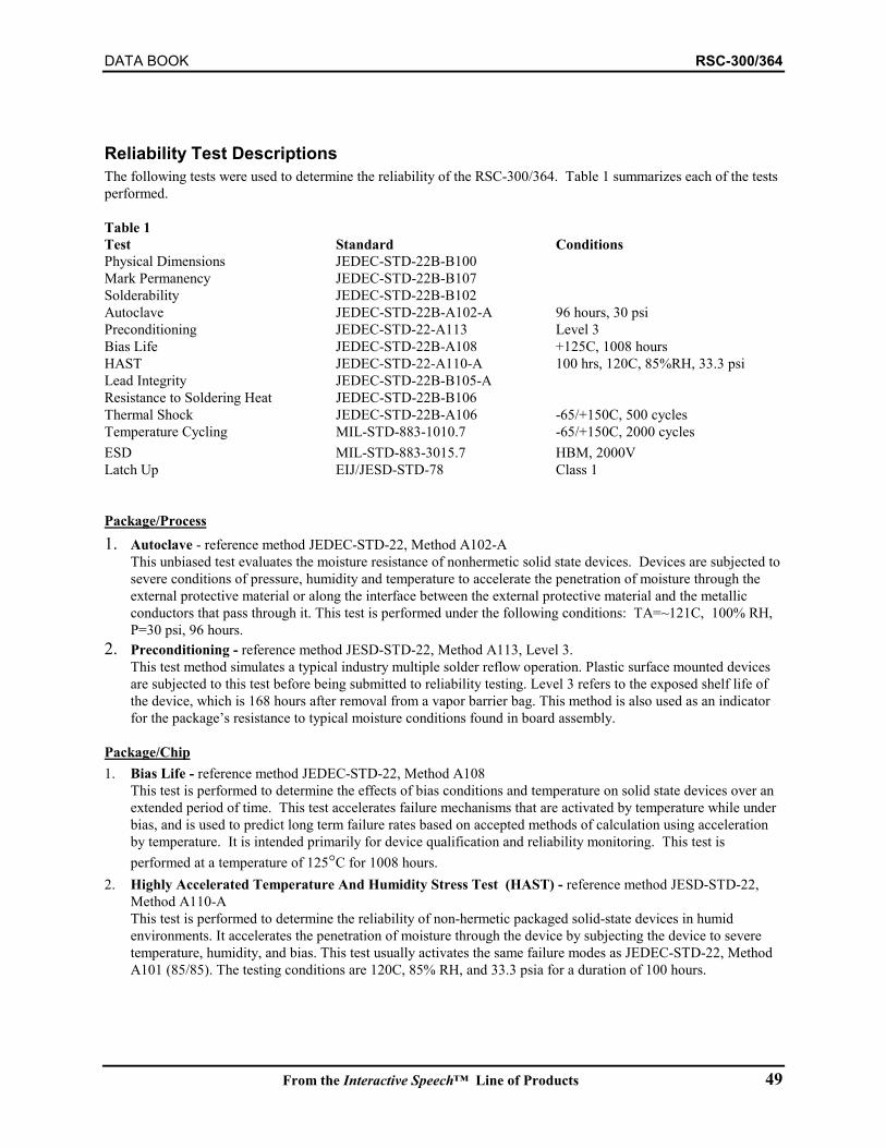
DATA BOOK RSC-300/364
From the Interactive Speech™ Line of Products 49
Reliability Test DescriptionsThe following tests were used to determine the reliability of the RSC-300/364. Table 1 summarizes each of the testsperformed.
Table 1Test Standard ConditionsPhysical Dimensions JEDEC-STD-22B-B100Mark Permanency JEDEC-STD-22B-B107Solderability JEDEC-STD-22B-B102Autoclave JEDEC-STD-22B-A102-A 96 hours, 30 psiPreconditioning JEDEC-STD-22-A113 Level 3Bias Life JEDEC-STD-22B-A108 +125C, 1008 hoursHAST JEDEC-STD-22-A110-A 100 hrs, 120C, 85%RH, 33.3 psiLead Integrity JEDEC-STD-22B-B105-AResistance to Soldering Heat JEDEC-STD-22B-B106Thermal Shock JEDEC-STD-22B-A106 -65/+150C, 500 cyclesTemperature Cycling MIL-STD-883-1010.7 -65/+150C, 2000 cyclesESD MIL-STD-883-3015.7 HBM, 2000VLatch Up EIJ/JESD-STD-78 Class 1
Package/Process1. Autoclave - reference method JEDEC-STD-22, Method A102-A
This unbiased test evaluates the moisture resistance of nonhermetic solid state devices. Devices are subjected tosevere conditions of pressure, humidity and temperature to accelerate the penetration of moisture through theexternal protective material or along the interface between the external protective material and the metallicconductors that pass through it. This test is performed under the following conditions: TA=~121C, 100% RH,P=30 psi, 96 hours.
2. Preconditioning - reference method JESD-STD-22, Method A113, Level 3.This test method simulates a typical industry multiple solder reflow operation. Plastic surface mounted devicesare subjected to this test before being submitted to reliability testing. Level 3 refers to the exposed shelf life ofthe device, which is 168 hours after removal from a vapor barrier bag. This method is also used as an indicatorfor the package’s resistance to typical moisture conditions found in board assembly.
Package/Chip1. Bias Life - reference method JEDEC-STD-22, Method A108
This test is performed to determine the effects of bias conditions and temperature on solid state devices over anextended period of time. This test accelerates failure mechanisms that are activated by temperature while underbias, and is used to predict long term failure rates based on accepted methods of calculation using accelerationby temperature. It is intended primarily for device qualification and reliability monitoring. This test isperformed at a temperature of 125°C for 1008 hours.
2. Highly Accelerated Temperature And Humidity Stress Test (HAST) - reference method JESD-STD-22,Method A110-AThis test is performed to determine the reliability of non-hermetic packaged solid-state devices in humidenvironments. It accelerates the penetration of moisture through the device by subjecting the device to severetemperature, humidity, and bias. This test usually activates the same failure modes as JEDEC-STD-22, MethodA101 (85/85). The testing conditions are 120C, 85% RH, and 33.3 psia for a duration of 100 hours.
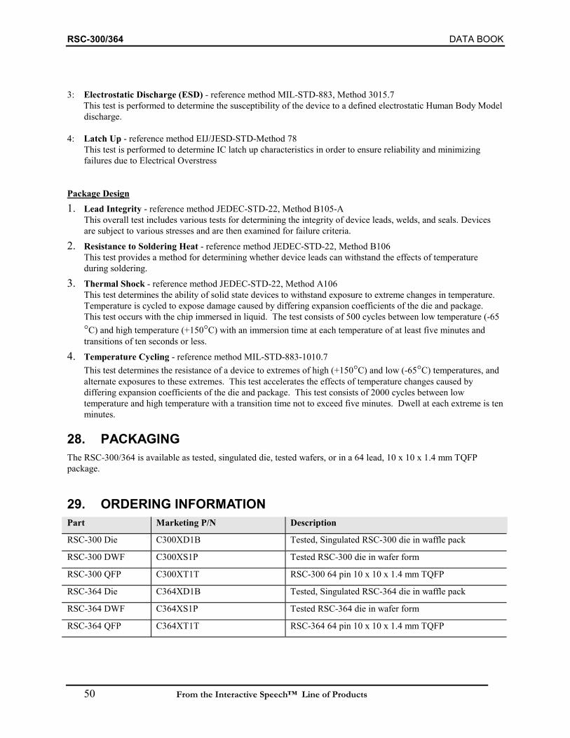
RSC-300/364 DATA BOOK
50 From the Interactive Speech™ Line of Products
3: Electrostatic Discharge (ESD) - reference method MIL-STD-883, Method 3015.7 This test is performed to determine the susceptibility of the device to a defined electrostatic Human Body Model
discharge.
4: Latch Up - reference method EIJ/JESD-STD-Method 78This test is performed to determine IC latch up characteristics in order to ensure reliability and minimizingfailures due to Electrical Overstress
Package Design1. Lead Integrity - reference method JEDEC-STD-22, Method B105-A
This overall test includes various tests for determining the integrity of device leads, welds, and seals. Devicesare subject to various stresses and are then examined for failure criteria.
2. Resistance to Soldering Heat - reference method JEDEC-STD-22, Method B106This test provides a method for determining whether device leads can withstand the effects of temperatureduring soldering.
3. Thermal Shock - reference method JEDEC-STD-22, Method A106This test determines the ability of solid state devices to withstand exposure to extreme changes in temperature.Temperature is cycled to expose damage caused by differing expansion coefficients of the die and package.This test occurs with the chip immersed in liquid. The test consists of 500 cycles between low temperature (-65°C) and high temperature (+150°C) with an immersion time at each temperature of at least five minutes andtransitions of ten seconds or less.
4. Temperature Cycling - reference method MIL-STD-883-1010.7This test determines the resistance of a device to extremes of high (+150°C) and low (-65°C) temperatures, andalternate exposures to these extremes. This test accelerates the effects of temperature changes caused bydiffering expansion coefficients of the die and package. This test consists of 2000 cycles between lowtemperature and high temperature with a transition time not to exceed five minutes. Dwell at each extreme is tenminutes.
28. PACKAGINGThe RSC-300/364 is available as tested, singulated die, tested wafers, or in a 64 lead, 10 x 10 x 1.4 mm TQFPpackage.
29. ORDERING INFORMATIONPart Marketing P/N Description
RSC-300 Die C300XD1B Tested, Singulated RSC-300 die in waffle pack
RSC-300 DWF C300XS1P Tested RSC-300 die in wafer form
RSC-300 QFP C300XT1T RSC-300 64 pin 10 x 10 x 1.4 mm TQFP
RSC-364 Die C364XD1B Tested, Singulated RSC-364 die in waffle pack
RSC-364 DWF C364XS1P Tested RSC-364 die in wafer form
RSC-364 QFP C364XT1T RSC-364 64 pin 10 x 10 x 1.4 mm TQFP
222
CHAPTER 9 - DESIGN NOTES
This chapter contains a collection of design and application notes related tocreating products bases on Sensory’s technologies. Additional notes, as wellas the latst version of all documentation, may be found on Sensory’s websiteat www.VoiceActivation.com.
In This Chapter
SELECTING AN INTERACTIVE SPEECH CHIP
DESIGN STEPS AND OPTIONS
DESIGNING WITH SPEECH RECOGNITION
SPEECH RECOGNITION HARDWARE DESIGN
MEMORY REQUIREMENTS
QUICK SYNTHESIS INSTRUCTIONS

Design NoteSelecting an Interactive Speech Chip
Sensory, Inc. 80-0078-2 1
Selecting an Interactive Speech Chip
The Interactive Speech™ Product LineThe Interactive Speech family of integrated circuits give product designers maximumflexibility and functionality in creating innovative products utilizing speech and audiotechnologies. Designers can choose from the RSC-series of chips: RSC-200/264T, RSC-300/364; from our Application Specific Standard Products (ASSP): Voice Direct 364,Voice Dialer™ 364, and Voice Extreme™.
RSC-200/264T and RSC-300/364The RSC-200/264T, RSC-300/364 are 8-bit microcontrollers featuring 64K of internalROM (RSC-264T and RSC-364 only), on-chip A/D and D/A converters, 16 general-purpose I/O lines, and an on-chip output amplifier. These microcontrollers arecustomized to perform the speech and audio functions in addition to product control. Alloffer Speaker-Dependent and Speaker-Independent Recognition, Speaker Verification,Voice Record and Playback, and Speech and Music Synthesis. All have an externalmemory bus that is configurable for serial or parallel operation, and can be custommasked.
The features and functions of the RSC-series of chips are summarized below:
Feature RSC-200/264T RSC-300/364Sensory Speech™ Technology Supported 4.x 4.x, 5.x, 6.xExternal Memory Bus Parallel or Serial Parallel or SerialPackage Die 64-QFP, DieCustom Mask Optional OptionalOn-Chip Microphone Preamp Yes YesOperating Voltage Range 2.4V-5.25V 2.4V-5.25VPower Down (Sleep Mode) Yes YesWords Stored on-chip 1 6Multi-word Continuous Listening No YesWordspotting No YesSimultaneous Record & Patgen No YesAverage Cost (100K, Die) <$3 <$4Samples Availability Now NowProduction Availability Now Now
It should be also noted that the RSC-300/364 includes hardware and software technologyto provide the highest level of recognition accuracy.
Selecting an Interactive Speech Chip Design Note
2 80-0078-2 Sensory, Inc.
ASSP: Voice DirectTM 364 ICThis non-programmable pin-configurable chip provides considerable functionality and isdesigned for easy implementation. The IC operates in two modes: stand-alone andexternal host. In stand-alone mode, it is fully pin configurable and does not require anexternal microcontroller.
External host mode allows the chip to be controlled by an external microcontroller,thereby providing a full set of chip capabilities to the external controller. This modeenables a product developer to easily integrate the IC into consumer electronic productsequipped with an existing microcontroller.
Voice DirectTM 364 is specifically designed for high performance, speaker-dependentspeech recognition, making it ideally suited for consumer telephony products. A usertrains the product in a quick and simple process, where the user says the words to berecognized twice. The trained words can then be recognized either with a button press, orvia Sensory’s hands-free Continuous Listening technology. Voice DirectTM 364 islanguage-independent and targeted to products that are customized by users.
ASSP: Voice Dialer™ 364 ICThis chip is designed for use as a slave chip controlled by an external host processor.The external host sends commands to control the operation of the chip, which include anumber of advanced speech technologies. Voice Dialer™ 364 features speechrecognition technology that allows users to dial phone numbers by saying the name of theperson they want to call. The Voice Dialer™ 364 chip manages a complete telephonedirectory, including name, phone number and speech recognition template. The VoiceDialer™ 364 IC is targeted for a broad number of cost-sensitive telephony applications.
ASSP: Voice Extreme™ ICVoice Extreme™ allows quick development of application programs using
Sensory Speech™ technologies. Voice Extreme allows a developer to write theapplication program in a higher-level “C-like” language on a PC, accessing the SensorySpeech technologies through calls to “built-in” functions. The Voice Extreme packagestreamlines development by:
• Allowing programs to be written in C, a commonly used higher level language• Allowing a simple means of linking the program and the data files it requires• Providing access to technology functions in a manner that conceals many of the
details
The short development time makes Voice Extreme™ ideal for prototypes and moderatevolume products. An application using the Voice Extreme™ ASSP would always includea 2MB Flash memory device.
Design Note Selecting an Interactive Speech Chip
Sensory, Inc. 80-0078-2 3
Selecting an Interactive Speech™ ChipIn selecting the optimal Interactive Speech chip for your product, a number of factorsneed to be considered. The main considerations involve:
1) The expected volume of the end product.2) Product development timeline.3) The speech and audio technologies desired.
• The type of speech recognition (Speaker-Independent vs. Speaker-Dependent)
• The type of speech synthesis (Customized speech vs. Standardizedspeech)
• The amount of ROM required for speech synthesis and recognition4) General product control.
• Does the product already have an existing microcontroller?
Expected Product QuantityExpected product volume is important because there are minimum volume requirementsfor our RSC chips. The RSC-series are general-purpose microcontrollers that must beprogrammed to perform the functions specific to a particular product. The RSC chips aremost cost-effective for high volume applications. (Quantities in excess of 100,000 areconsidered high volume and quantities under 100,000 are considered low volumes.)
The Voice Direct™ 364 and Voice Dialer™ 364 chips perform specific functions. Thesechips require no additional programming or speech support from Sensory and can beeasily integrated into a product. As with all Sensory ASSPs, there are no minimumvolume requirements for these chips, making them ideal for both low and high volumeproducts.
Timeline of Product DevelopmentThe RSC chips require generally 4-9 months of development time. Developmentinvolves detailed product design including hardware and software. Integrating speechinto a product with Voice Direct™ 364 or Voice Dialer™ 364 chips is less extensive thanthe RSC chips, since these chips require no internal custom software. Voice Extreme™requires programming, but this can be done in a C-like language, thereby simplifyingsoftware development.
Speech and Audio Technologies DesiredThe actual capabilities of a particular product using Interactive Speech ICs are restrictedonly by the product’s desired functions and available memory.
As previously mentioned, the ASSP chips feature specific technologies. The VoiceDialer™ 364 chip features speaker-dependent technology and DTMF tone generationcapabilities. Voice Extreme™ offers access to most, but not all RSC technologies.
Selecting an Interactive Speech Chip Design Note
4 80-0078-2 Sensory, Inc.
Types of Speech RecognitionSensory offers both speaker-independent and speaker-dependent speech recognition.Speaker-independent speech recognition is designed to recognize pre-determined wordsspoken by any user and is language-dependent. Speaker-dependent recognition is user-trained speech recognition where a user trains the product to recognize specific words.Speaker-dependent speech recognition is not language-dependent. Speaker-dependenthas a typically higher accuracy rate than speaker-independent recognition.
Both speaker-dependent and speaker-independent recognition are available on the RSCchips. The RSC-300/364 also supports Dual Recognition Technology, which provideshigher recognition than either speaker-dependent or speaker independent alone, as well asWordspotting, which is the ability to recognize a word or phrase out of the middle of asentence. See Sensory for more information regarding this technology.
Speech SynthesisUsing speech synthesis in a product allows a product to interact with the user byproviding prompts and cues on using, programming and troubleshooting a product.
Product designers can choose to use standardize speech synthesis or customized speechsynthesis. With the RSC chips, designers have the option of using standardized orcustomized speech synthesis. With Voice Direct™ 364, and Voice Dialer™ 364 onlystandardized speech synthesis is available. Product designers who wish to customizespeech synthesis with our ASSP chips need to contact Sensory for more details.
Product ControlThe RSC and Voice Extreme™ chips integrate a fully programmable 8-bitmicrocontroller that can function as the main microcontroller or as an adjunct processor.Voice Direct™ 364 is a non-programmable, pin-configurable chip that can operate in astand-alone mode or in conjunction with an existing microcontroller. Voice Dialer™364 requires an external host processor.
SummaryIn discussing the different considerations involved in selecting an Interactive Speechchip, please refer to the previous table summarizing the different speech and audiocapabilities of each chip along with its individual features and benefits. Additionalinformation can be found on our website at www.VoiceActivation.com, or by emailing usat [email protected].
521 East Weddell DriveSunnyvale, CA 94089
TEL: (408) 744-9000FAX: (408)744-1299
IMPORTANT NOTICEReasonable efforts have been made to verify theaccuracy of information contained herein, however noguarantee can be made of accuracy or applicability.Sensory reserves the right to change any specificationor description contained herein.
Design NoteDesign Steps and Options
80-0079-2 1Sensory, Inc.
This document outlines the various design steps and design options available to a productdesigner who is using an Interactive Speech chip. Each design step is detailed with variousconsiderations that are important in creating a high quality, high accuracy, speech recognitionproduct.
Design Steps and Design OptionsThe design of a complete product using the Interactive Speech™ line of chips includes thefollowing six steps:
1. Creation of product specification2. Review of product specification by Sensory (Recommended)3. Selection of product developer4. Development of prototype5. Hardware review of product6. Manufacture of product
The first four steps will take approximately 4-6 months to complete. Each of the design stepsdiscussed relate only to integrating speech into the consumer product, and do not cover otherproduct design issues associated with the consumer product.
To assist customers, Sensory offers a variety of services and resources to help customers througheach of the various design steps. A description of Sensory services can be found in the lastsection of this document.
Creating a Product SpecificationA detailed specification for the product serves as the guide for using the speech capabilities of anInteractive SpeechTM chip. It is extremely important to create a complete product specificationto avoid potential delays that can occur later on in product development.
A detailed product specification should contain the following information:• An outline of the product concept• An exact description of what the product does, usually in the form of a flow chart• An exact description of what the product interacts with (lights, switches…)• Selection of the appropriate Interactive SpeechTM chip• Documentation of the speech recognition vocabulary (if any)• Documentation of the speech synthesis vocabulary (if any)
Although Sensory can provide services to help designers better define product concepts andidentify speech needs, the customer is responsible for the final product specification.
Design Steps and Options Design Note
2 80-0079-2 Sensory, Inc.
Sensory Review of SpecificationIt is highly recommended that customers send in preliminary product specifications to Sensoryfor review. Sensory’s Application Engineers have considerable experience incorporating speechrecognition into a variety of products and can help identify potential problems that are oftenoverlooked in incorporating speech recognition and speech synthesis.
This stage of development will finalize which Interactive Speech™ IC is best for the product andidentify the additional electronic components needed to implement the product.
Selecting an Interactive Speech™ DeveloperCustomers can choose from several options:
1. Customers can develop the product themselves2. Customers can contract development services from Sensory3. Customers can use an independent development house.
For designs with the RSC-200/264T, and RSC-300/364 Sensory offers dedicated DevelopmentKits for each IC. Each Development Kit provides all software and hardware tools needed forexperienced product developers to integrate Interactive Speech™ chips into a consumer product.Products using Voice Extreme™ can be created using a low-cost development kit for developerswith basic C-language experience. Applications using Voice DialerTM 364 or Voice DirectTM 364do not require a development kit, but will in most cases require the programming of an externalmicrocontroller.
If Sensory is chosen to develop a product using an RSC chip, the following services areavailable:
• Speaker-Independent recognition sets, speech synthesis files, and music synthesis files.• Application coding of the RSC.• Hardware design of the electronics associated with the Sensory chips.
Sensory will provide any requested speaker-independent recognition sets, speech synthesis files,and music synthesis files, even if Sensory is not providing software development services.

Design Note Design Steps and Options
Sensory, Inc. 80-0079-2 3
The following table outlines the steps involved in developing a product and the responsibilitiesof those parties involved with product development.
Action Sensory As Developer Other DeveloperProduct definition Sensory assists customer* Customer or developerSpecification review Sensory Sensory assists customer or developerSpeaker-independent recognition sets Sensory SensorySpeaker-dependent recognition sets No development required No development requiredSpeech Synthesis Sensory Sensory, or developer with speech
development kit**Music Sensory SensoryApplication coding Sensory Developer with RSC development kitCircuit diagram Sensory DeveloperBill of materials Sensory Developer or manufacturerPCB layout Manufacturer Developer or manufacturerManufacturing of product Manufacturer Manufacturer
* Sensory is not responsible for any deliverables. Also note that “development” is not the same as “projectmanagement”; Sensory is not a manufacturer nor can we manage or be responsible for the efforts of manufacturers.
Product Prototype DevelopmentAfter the product is properly defined, a prototype can be built. A functioning prototype isimportant for ensuring that the product will work as envisioned. There is often some fine-tuningrequired after a prototype is built and tested. The amount of time needed to revise a productdepends on the type of change required. Small changes to the product’s application flow canusually be made relatively quickly. Changes to the product’s speech synthesis are more timeconsuming and can take several weeks, or longer, if a new recording session is required. (Thisdoes not apply if Sensory’s Quick Synthesis application is used for creating speech.) Changes tospeaker-independent recognition words, although sometimes simple, may take months if newwords need to be recorded for the set (each word requires approximately 500 recorded voices).
Hardware Review (Important)Speech recognition circuitry is extremely sensitive to noise. Therefore, proper design and PCBlayout is essential. Before going to production, the developer should carefully check out thehardware design as well as the microphone housing. Please refer to Design Notes for HardwareDesign for the steps to review a hardware design. Sensory can also provide hardware review-please see your application engineer for more detail.
Product ManufacturingAfter the prototype is completed and accepted, there are three steps that must still be completed:
1) Select Chip Packaging. Prices quoted by Sensory are for chips in die form, unlessotherwise specified. The RSC-200/264T is currently available in die form only,whereas all other chips are offered in die and 64-lead TQFP. PLCC versions of allRSC ICs are available for use with Development Kits.
2) Order chips. Sensory has a typical order lead time of three months. Custom-maskedversions of ICs obviously cannot be stocked. All code must be frozen prior to

Design Steps and Options Design Note
4 80-0079-2 Sensory, Inc.
ordering custom masked chips. Once masked, the code on these chips cannot bechanged.
3) Start product manufacturing. This begins once chips are received from Sensoryand all program code is available.
Sample Timeline for Product DevelopmentThe following is a timeline for product development when Sensory and the customer worktogether to create a new product.
Product Definition Application flow defined
Recognition vocabulary proposed Synthesis vocabulary proposed
Timetable: Customer dependent
Chip Production & TestCustom mask created (if necessary)
Wafers producedWafer probed and diced
Chips are packaged (if requested)
Timetable: 3 months
Specification Complete Specification ReviewBy Sensory
Vocabulary reviewedProduct design reviewed, if requested
Suggestions provided
Timetable: 1 week to 1 monthPrototype DevelopedVocabulary recorded
Neural network trainedSpeech compressed
Code written & PCB designed
Timetable: 1-3 months
Quote accepted
Prototypeaccepted
Productioncomplete
Product Manufacturing(by customer)
Design Note Design Steps and Options
Sensory, Inc. 80-0079-2 5
Sensory Support ServicesSensory offers many services to support development of those products using theInteractive Speech ™ line of chips. For each service, there is a required amount ofinformation about the product that the product designer must provide to Sensory.
Application ProgrammingApplication programming for the RSC is available at hourly labor rates. Project quotesare also available.
Circuit DesignCircuit design services are available at hourly rates to design the circuitry using anInteractive Speech™ chip. Project quotes are also available.
Other Support ServicesProduct design, product definition and any other support services are available byarrangement.
Design Steps and Options Design Note
6 80-0079-2 Sensory, Inc.
521 East Weddell DriveSunnyvale, CA 94089
TEL: (408) 744-9000FAX: (408)744-1299
IMPORTANT NOTICEReasonable efforts have been made to verify theaccuracy of information contained herein, however noguarantee can be made of accuracy or applicability.Sensory reserves the right to change any specificationor description contained herein.
Design NoteDesigning with Speech Recognition
80-0080-2 1Sensory, Inc.
Designing with Speech RecognitionThe successful application of speech recognition in a product depends heavily on thespecification of the product and the recognition technology used. This document provides anoverview of the speech recognition technologies and design guidelines for increasing thereliability of speech recognition in consumer products. Effective use of the speech recognitiontechnologies can not only enhance recognition accuracy, but also reduce memory requirements,and overall product cost.
Speech Recognition: Dependent vs. IndependentThrough proper design and specification it is easy to create a product that is 99.5% accurateusing the Interactive Speech™ technology. Determining the type of speech recognition to use isone key element in the product’s specification.
The two general classes of speech recognition are “speaker-dependent” and “speaker-independent” recognition. With speaker-dependent recognition, the user trains the device torecognize his/her voice by speaking each of the words to be recognized several times. Theproduct then recognizes these pre-trained words when spoken by the user. Training is a quickand simple process. In speaker-independent recognition, the product is pre-trained on the voicesof many different speakers. The product is ready to use and requires no additional training by theuser.
Speaker-dependent recognition yields slightly higher recognition rates than speaker-independentspeech recognition because it is trained on a specific user’s voice. For example, a speaker-dependent device recognizing the digits from 0 through 9 will have an accuracy higher than 99%,while a speaker-independent device performing the same task may have a recognition rate a fewpercentage points lower. Speaker-dependent recognition devices are ideal for applicationsrequiring complicated recognition tasks. Speaker-dependent recognition systems will requirestorage of information about the speaker’s voice; and thus, depending on the number of wordsand the Sensory processor chosen, these products may require some type of external memory(SRAM, EEPROM, or Flash).
Through proper product design, speaker-independent devices can yield high recognition rates.For example, a speaker-independent recognizer that distinguishes “yes” from “no” will have anaccuracy higher than 99% because the recognition task is simple. More complicated recognitiontasks can be performed with an accuracy just a few percentage points lower than speaker-dependent recognition if the product is designed carefully. Product design includes carefuldefinition of the product’s target users. This is extremely important in enhancing speaker-independent recognition rates. Speakers’ accents, age, gender, as well as regional, socio-economic, and ethnic backgrounds are demographics that must be taken into consideration whenpre-training the product for speaker-independent speech recognition.
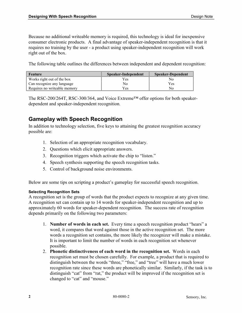
Designing With Speech Recognition Design Note
2 80-0080-2 Sensory, Inc.
Because no additional writeable memory is required, this technology is ideal for inexpensiveconsumer electronic products. A final advantage of speaker-independent recognition is that itrequires no training by the user - a product using speaker-independent recognition will workright out of the box.
The following table outlines the differences between independent and dependent recognition:
Feature Speaker-Independent Speaker-DependentWorks right out of the box Yes NoCan recognize any language No YesRequires no writeable memory Yes No
The RSC-200/264T, RSC-300/364, and Voice Extreme™ offer options for both speaker-dependent and speaker-independent recognition.
Gameplay with Speech RecognitionIn addition to technology selection, five keys to attaining the greatest recognition accuracypossible are:
1. Selection of an appropriate recognition vocabulary.2. Questions which elicit appropriate answers.3. Recognition triggers which activate the chip to “listen.”4. Speech synthesis supporting the speech recognition tasks.5. Control of background noise environments.
Below are some tips on scripting a product’s gameplay for successful speech recognition.
Selecting Recognition SetsA recognition set is the group of words that the product expects to recognize at any given time.A recognition set can contain up to 14 words for speaker-independent recognition and up toapproximately 60 words for speaker-dependent recognition. The success rate of recognitiondepends primarily on the following two parameters:
1. Number of words in each set. Every time a speech recognition product “hears” aword, it compares that word against those in the active recognition set. The morewords a recognition set contains, the more likely the recognizer will make a mistake.It is important to limit the number of words in each recognition set wheneverpossible.
2. Phonetic distinctiveness of each word in the recognition set. Words in eachrecognition set must be chosen carefully. For example, a product that is required todistinguish between the words “three,” “free,” and “tree” will have a much lowerrecognition rate since these words are phonetically similar. Similarly, if the task is todistinguish “cat” from “rat,” the product will be improved if the recognition set ischanged to “cat” and “mouse.”
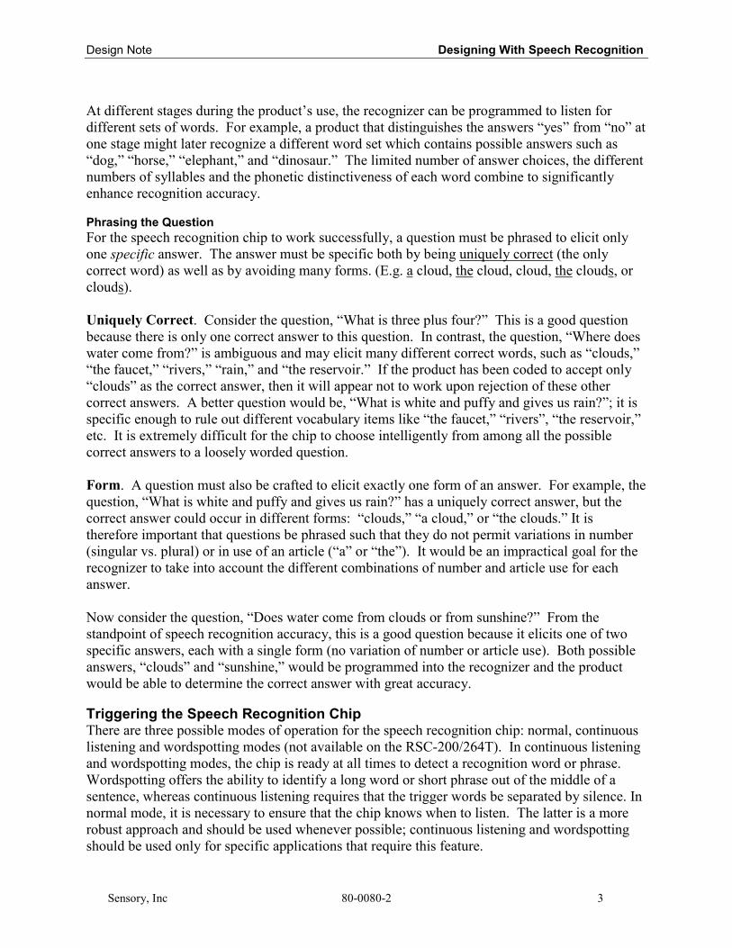
Design Note Designing With Speech Recognition
Sensory, Inc 80-0080-2 3
At different stages during the product’s use, the recognizer can be programmed to listen fordifferent sets of words. For example, a product that distinguishes the answers “yes” from “no” atone stage might later recognize a different word set which contains possible answers such as“dog,” “horse,” “elephant,” and “dinosaur.” The limited number of answer choices, the differentnumbers of syllables and the phonetic distinctiveness of each word combine to significantlyenhance recognition accuracy.
Phrasing the QuestionFor the speech recognition chip to work successfully, a question must be phrased to elicit onlyone specific answer. The answer must be specific both by being uniquely correct (the onlycorrect word) as well as by avoiding many forms. (E.g. a cloud, the cloud, cloud, the clouds, orclouds).
Uniquely Correct. Consider the question, “What is three plus four?” This is a good questionbecause there is only one correct answer to this question. In contrast, the question, “Where doeswater come from?” is ambiguous and may elicit many different correct words, such as “clouds,”“the faucet,” “rivers,” “rain,” and “the reservoir.” If the product has been coded to accept only“clouds” as the correct answer, then it will appear not to work upon rejection of these othercorrect answers. A better question would be, “What is white and puffy and gives us rain?”; it isspecific enough to rule out different vocabulary items like “the faucet,” “rivers”, “the reservoir,”etc. It is extremely difficult for the chip to choose intelligently from among all the possiblecorrect answers to a loosely worded question.
Form. A question must also be crafted to elicit exactly one form of an answer. For example, thequestion, “What is white and puffy and gives us rain?” has a uniquely correct answer, but thecorrect answer could occur in different forms: “clouds,” “a cloud,” or “the clouds.” It istherefore important that questions be phrased such that they do not permit variations in number(singular vs. plural) or in use of an article (“a” or “the”). It would be an impractical goal for therecognizer to take into account the different combinations of number and article use for eachanswer.
Now consider the question, “Does water come from clouds or from sunshine?” From thestandpoint of speech recognition accuracy, this is a good question because it elicits one of twospecific answers, each with a single form (no variation of number or article use). Both possibleanswers, “clouds” and “sunshine,” would be programmed into the recognizer and the productwould be able to determine the correct answer with great accuracy.
Triggering the Speech Recognition ChipThere are three possible modes of operation for the speech recognition chip: normal, continuouslistening and wordspotting modes (not available on the RSC-200/264T). In continuous listeningand wordspotting modes, the chip is ready at all times to detect a recognition word or phrase.Wordspotting offers the ability to identify a long word or short phrase out of the middle of asentence, whereas continuous listening requires that the trigger words be separated by silence. Innormal mode, it is necessary to ensure that the chip knows when to listen. The latter is a morerobust approach and should be used whenever possible; continuous listening and wordspottingshould be used only for specific applications that require this feature.
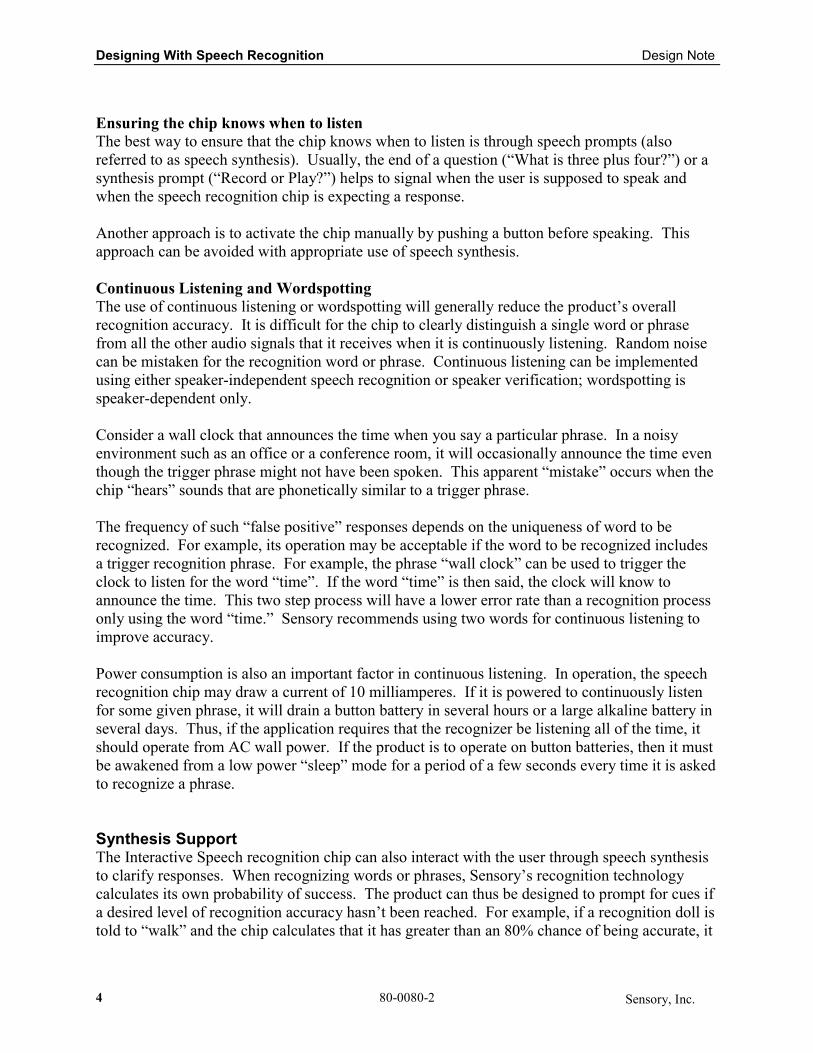
Designing With Speech Recognition Design Note
4 80-0080-2 Sensory, Inc.
Ensuring the chip knows when to listenThe best way to ensure that the chip knows when to listen is through speech prompts (alsoreferred to as speech synthesis). Usually, the end of a question (“What is three plus four?”) or asynthesis prompt (“Record or Play?”) helps to signal when the user is supposed to speak andwhen the speech recognition chip is expecting a response.
Another approach is to activate the chip manually by pushing a button before speaking. Thisapproach can be avoided with appropriate use of speech synthesis.
Continuous Listening and WordspottingThe use of continuous listening or wordspotting will generally reduce the product’s overallrecognition accuracy. It is difficult for the chip to clearly distinguish a single word or phrasefrom all the other audio signals that it receives when it is continuously listening. Random noisecan be mistaken for the recognition word or phrase. Continuous listening can be implementedusing either speaker-independent speech recognition or speaker verification; wordspotting isspeaker-dependent only.
Consider a wall clock that announces the time when you say a particular phrase. In a noisyenvironment such as an office or a conference room, it will occasionally announce the time eventhough the trigger phrase might not have been spoken. This apparent “mistake” occurs when thechip “hears” sounds that are phonetically similar to a trigger phrase.
The frequency of such “false positive” responses depends on the uniqueness of word to berecognized. For example, its operation may be acceptable if the word to be recognized includesa trigger recognition phrase. For example, the phrase “wall clock” can be used to trigger theclock to listen for the word “time”. If the word “time” is then said, the clock will know toannounce the time. This two step process will have a lower error rate than a recognition processonly using the word “time.” Sensory recommends using two words for continuous listening toimprove accuracy.
Power consumption is also an important factor in continuous listening. In operation, the speechrecognition chip may draw a current of 10 milliamperes. If it is powered to continuously listenfor some given phrase, it will drain a button battery in several hours or a large alkaline battery inseveral days. Thus, if the application requires that the recognizer be listening all of the time, itshould operate from AC wall power. If the product is to operate on button batteries, then it mustbe awakened from a low power “sleep” mode for a period of a few seconds every time it is askedto recognize a phrase.
Synthesis SupportThe Interactive Speech recognition chip can also interact with the user through speech synthesisto clarify responses. When recognizing words or phrases, Sensory’s recognition technologycalculates its own probability of success. The product can thus be designed to prompt for cues ifa desired level of recognition accuracy hasn’t been reached. For example, if a recognition doll istold to “walk” and the chip calculates that it has greater than an 80% chance of being accurate, it

Design Note Designing With Speech Recognition
Sensory, Inc 80-0080-2 5
can accept the “walk” command. If it is only 50-80% sure of its accuracy, the recognizer canprompt, “Did you say walk?” The answer, “yes” or “no,” is very easy for the chip to determineand this provides a robust method of (eventually) getting the right answer. If less than 50%confidant, the chip can ask, “What did you say?” effectively starting the recognition task over.
The following phrases should be included in all products using synthesis. These phrases willhelp improve overall product accuracy by notifying the user of possible problems.
• Please talk louder / Please talk into the microphone.• Please talk softer.• Please say...[each recognition item].• Did you say... [each recognition item]?• What did you say?• You spoke too soon.
The following phrases may be desirable, depending on the product:• I think you said...[each recognition item].• In the picture, what do you see that ...
Controlling the Noise EnvironmentJust like people, speech recognition systems have difficulty recognizing words in a noisyenvironment. Speech recognition products should be designed for use in a quiet environmentwhenever possible. If the product is meant to be used in a noisy environment, care must be takento try to control the noise. For example, consider speech recognition being used in a video gamewith shoot-’em-up noise and music. Either the user should be provided with headphones forlistening to the sounds (without their being heard by the microphone), or the sounds should bemuted when the user is expected to talk, or a headset microphone should be used to provide agood voice signal to the recognition system.
Designing with SynthesisSynthesis is the product’s ability to “talk.” The use of music, sound effects and speech synthesiscan be easily incorporated to produce a product that is interactive and user-friendly. Speechsynthesis allows the product to interact with user to provide feedback or directions as to how tobetter use the product. Although synthesis does require additional memory which can increaseoverall product cost, it’s overall value to the end user is priceless.
Speech Synthesis OverviewCreating speech synthesis files for the Interactive Speech™ chips begins with making a list of allwords/phrases the product will ever say. From this list, a recording script will be generated. IfSensory is performing the speech synthesis development, then the recording script and allsubsequent steps will be done for you. If not, then the next step is to use a voice talent to recordphrases based on the script. After recording, the best of all the recorded files must be chosen foruse in the product. These files are then compressed into one master file (a .O file) that adeveloper will use to make the chip talk. This can be done either by Sensory, or by the developerusing Sensory’s Quick Synthesis application. Creating speech synthesis using Quick Synthesis
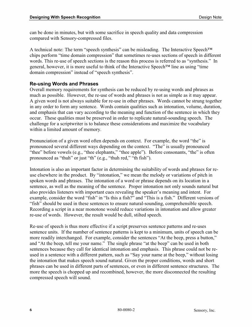
Designing With Speech Recognition Design Note
6 80-0080-2 Sensory, Inc.
can be done in minutes, but with some sacrifice in speech quality and data compressioncompared with Sensory-compressed files.
A technical note: The term “speech synthesis” can be misleading. The Interactive Speech™chips perform “time domain compression” that sometimes re-uses sections of speech in differentwords. This re-use of speech sections is the reason this process is referred to as “synthesis.” Ingeneral, however, it is more useful to think of the Interactive Speech™ line as using “timedomain compression” instead of “speech synthesis”.
Re-using Words and PhrasesOverall memory requirements for synthesis can be reduced by re-using words and phrases asmuch as possible. However, the re-use of words and phrases is not as simple as it may appear.A given word is not always suitable for re-use in other phrases. Words cannot be strung togetherin any order to form any sentence. Words contain qualities such as intonation, volume, duration,and emphasis that can vary according to the meaning and function of the sentence in which theyoccur. These qualities must be preserved in order to replicate natural-sounding speech. Thechallenge for a scriptwriter is to balance these considerations and maximize the vocabularywithin a limited amount of memory.
Pronunciation of a given word often depends on context. For example, the word “the” ispronounced several different ways depending on the context. “The” is usually pronounced“thee” before vowels (e.g., “thee elephants,” “thee apple”). Before consonants, “the” is oftenpronounced as “thuh” or just “th” (e.g., “thuh red,” “th fish”).
Intonation is also an important factor in determining the suitability of words and phrases for re-use elsewhere in the product. By “intonation,” we mean the melody or variations of pitch inspoken words and phrases. The intonation of a word or phrase depends on its location in asentence, as well as the meaning of the sentence. Proper intonation not only sounds natural butalso provides listeners with important cues revealing the speaker’s meaning and intent. Forexample, consider the word “fish” in “Is this a fish?” and “This is a fish.” Different versions of“fish” should be used in these sentences to ensure natural-sounding, comprehensible speech.Recording a script in a near monotone would reduce variations in intonation and allow greaterre-use of words. However, the result would be dull, stilted speech.
Re-use of speech is thus more effective if a script preserves sentence patterns and re-usessentence units. If the number of sentence patterns is kept to a minimum, units of speech can bemore readily interchanged. For example, consider the sentences “At the beep, press a button,”and “At the beep, tell me your name.” The single phrase “at the beep” can be used in bothsentences because they call for identical intonation and emphasis. This phrase could not be re-used in a sentence with a different pattern, such as “Say your name at the beep,” without losingthe intonation that makes speech sound natural. Given the proper conditions, words and shortphrases can be used in different parts of sentences, or even in different sentence structures. Themore the speech is chopped up and recombined, however, the more disconnected the resultingcompressed speech will sound.

Design Note Designing With Speech Recognition
Sensory, Inc 80-0080-2 7
Counting Words in a ScriptIt is essential to estimate how much memory will be required and what level of effort/cost will beassociated with compressing the speech synthesis phrases. These factors effect the overall costof the product and its development. Counting words is the best way to approximate the totalrequirements. It is usually best to count words conservatively (e.g., count “fireman” and“firehouse” as two words each).
Each time a word is said in a different sentence, in a different way, or surrounded by differentwords, that word should be counted again. For a conservative estimate it is best to repeatphrases, not words. Sensory’s team of expert linguists can evaluate phrase lists and determinehow words or phrases may be formulated for re-use within the product.
Synthesis in More DetailThis section details exactly how much sound (words, character-voices, sound effects, music,beeps, and bells) can fit on an RSC-264T or RSC-364. The total amount depends on bothsubjective (e.g. sound quality) and qualitative (e.g. compression rate) factors.
The procedure for determining the number of seconds of sound playback available: Calculate theamount of available ROM (in bits) and divide by the data rate (bits/second) for the sound youwant played back.
Available ROMThe RSC-264T and RSC-364 chips have 64 kilobytes (that’s 64,000 bytes or 64,000 x 8 =512,000 bits) of ROM on-chip – but not all of it is available for sound output. The ROM space isused for other functions, like speech recognition. Ultimately, even a product with an emphasison speech output will have under 50kB (400,000 bits) of ROM available on-chip for thecustomer to store sound output. The customer can add as much off-chip ROM or Flash asdesired in order to increase the sound capability of the product. External ROM or Flash isrequired with the RSC-200 and RSC-300. Voice Extreme™ is designed to operate in conjunctionwith a 2MB Flash memory device.
Data RateSound exists as an analog signal that must be converted to a digital signal for storage on a chip.During this conversion, recorded sound is compressed to reduce the amount of storage neededon-chip. The RSC IC can compress sound down to data rates from 15,000 bits/sec to under 5,000bits/sec. The data rate depends on the following factors:1) Desired quality. Sound compression involves a tradeoff between quality and quantity. The
more we compress the sound, the more will fit on the chip. The less we compress it, thebetter it sounds. This is subjective; what sounds great to a toy designer may sound horribleto an audiophile.
2) Nature of the sound. Some sounds compress better than others. If a customer wanted theproduct to sound like a robot, then we could achieve very low data rates (under 5,000bits/sec). However, a high-pitched voice, such as a licensed reproduction of Minnie Mouse,might require more than 15,000 bits/sec. There are two reasons for this. First, we want toretain the personality of Minnie Mouse’s voice. Second, high-pitched sounds don’t compress
Designing With Speech Recognition Design Note
8 80-0080-2 Sensory, Inc.
as well as low-pitched ones. As another example, sound effects are often very difficult tocompress, requiring up to 20,000 bits/sec.
3) Repeatability of the sound. After you use a sound once, you can use it again withoutrequiring extra memory. This can happen on several different levels. Sound effects, forexample, can be looped such that a single “whomp” plays repeatedly to produce the sound ofa helicopter: “whomp whomp whomp whomp...” Words and phrases can also be re-used inthe same part of different sentences or, sometimes, in different parts of sentences. Our abilityto do this depends on several factors: the desired quality, the script, and the intonation of thewords and phrases selected for use in synthesis.
As a baseline, a custom masked RSC can fit from 25 to over 100 seconds of sound on-chip. Aword usually takes about 0.5 sec and a sound effect about 1sec. Therefore, the RSC chips can fitfrom approximately 50 to 200 words on-chip. As mentioned previously, additional sound can bestored in off-chip ROM or Flash.
Sensory Support ServicesSensory offers a variety of services and resources to help product designers integrate speech intotheir products.
Speaker-Independent Recognition SetsCurrently it is required that Sensory creates the independent recognition sets for use with theInteractive SpeechTM chips for all customers. This section identifies the information and stepsrequired for building speaker-independent sets.
The following information is required to create the sets:
1. List of recognition words divided into appropriate recognition sets.
2. Description of the environment the product will be used in.
3. Recordings of approximately 500 people saying the entire word list. Thedemographics of this pool must accurately reflect that of the product’s target market.
4. Sample background noises.
The recognition list (include English translation if appropriate) should be arranged with thewords in a single list as well as in their respective sets. The following is an example of arecognition list for a simple record and playback device:
Set 1: Set 2: Entire List:1. Record 1. Yes Record2. Play 2. No Play3. Erase Erase
YesNo
Sensory will review the word list, paying careful attention to the selections in each set in order toensure accurate recognition. If Sensory does not foresee any problems, then theacquisition/recordings of the appropriate words can start.
Design Note Designing With Speech Recognition
Sensory, Inc 80-0080-2 9
To record voices, an IBM PC or compatible computer with a high quality sound card is required.Sensory will support the customer or sales rep as needed.
Speech SynthesisSensory has available services that allow them to add speech synthesis to their products. Currentprocedure requires that Sensory create the speech synthesis files for use with the InteractiveSpeech™ chips. In order for Sensory to create synthesis files, the customer should create aphrase list containing every phrase to be spoken by the product.
The phrase list should contain all phrases to be said by the product. Include a translation intoEnglish if appropriate. No phrase or word concatenation should be performed at this stage. Anexample of a phrase list for a simple record and playback device follows:
Example:1. Record, play, or erase?2. Recording.3. Playback.4. Erased.5. Please talk louder.6. Please talk softer.7. It is too noisy here.8. Just say: record, play, or erase.9. Did you say “record”?10. Did you say “play”?11. Did you say “erase”?12. Please wait until I’m finished / Please wait for the beep.13. What did you say?
A development station is being designed that will enable customers to create their own synthesisfiles. Contact Sensory for further information.
Music SynthesisSensory also provides customers with services that allow them to use music synthesis in theirproducts. Currently Sensory creates the music synthesis files for use with the InteractiveSpeech™ chips for customers. In order for Sensory to compress musical compositions for useon
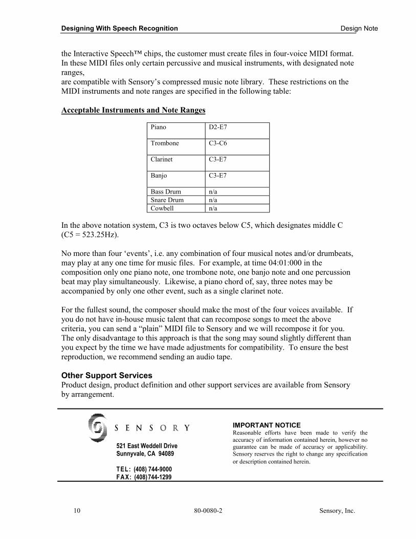
Designing With Speech Recognition Design Note
10 80-0080-2 Sensory, Inc.
the Interactive Speech™ chips, the customer must create files in four-voice MIDI format.In these MIDI files only certain percussive and musical instruments, with designated noteranges,are compatible with Sensory’s compressed music note library. These restrictions on theMIDI instruments and note ranges are specified in the following table:
Acceptable Instruments and Note Ranges
Piano D2-E7
Trombone C3-C6
Clarinet C3-E7
Banjo C3-E7
Bass Drum n/aSnare Drum n/aCowbell n/a
In the above notation system, C3 is two octaves below C5, which designates middle C(C5 = 523.25Hz).
No more than four ‘events’, i.e. any combination of four musical notes and/or drumbeats,may play at any one time for music files. For example, at time 04:01:000 in thecomposition only one piano note, one trombone note, one banjo note and one percussionbeat may play simultaneously. Likewise, a piano chord of, say, three notes may beaccompanied by only one other event, such as a single clarinet note.
For the fullest sound, the composer should make the most of the four voices available. Ifyou do not have in-house music talent that can recompose songs to meet the abovecriteria, you can send a “plain” MIDI file to Sensory and we will recompose it for you.The only disadvantage to this approach is that the song may sound slightly different thanyou expect by the time we have made adjustments for compatibility. To ensure the bestreproduction, we recommend sending an audio tape.
Other Support ServicesProduct design, product definition and other support services are available from Sensoryby arrangement.
521 East Weddell DriveSunnyvale, CA 94089
TEL: (408) 744-9000FAX: (408)744-1299
IMPORTANT NOTICEReasonable efforts have been made to verify theaccuracy of information contained herein, however noguarantee can be made of accuracy or applicability.Sensory reserves the right to change any specificationor description contained herein.

Design NoteSpeech Recognition
Hardware Design
80-0073-6Sensory, Inc. 1
Speech Recognition Hardware DesignIntroductionProper hardware design is essential to creating a high quality speech recognition product. TheInteractive Speech™ ICs have the best speech recognition quality/cost ratio available today, butwithout an effective hardware design, the performance of these ICs will be severely degraded.This design note focuses on hardware issues, guiding the reader through important hardwaredesign considerations. This note should be used in conjunction with the other InteractiveSpeech™ design notes to ensure the creation of a high quality speech recognition product.Sensory highly recommends that this procedure be used to design and test ALL newproduct designs.
Table of ContentsSPEECH RECOGNITION HARDWARE DESIGN 1
MICROPHONE 2
SELECTING A SUITABLE MICROPHONE 2DESIGN OF MICROPHONE HOUSING 2
PCB DESIGN 6
ANALOG SECTION 6LAYOUT REQUIREMENT 8LOCATING AND MOUNTING INTERACTIVE SPEECH ICS 8
CIRCUIT VERIFICATION PROCEDURE 9
PROCEDURE 9

Speech Recognition Hardware Design Design Note
80-0073-6 Sensory, Inc.9-22
Microphone
Selecting a Suitable MicrophoneFor most applications, an inexpensive omni-directional electret capacitor microphone with aminimum sensitivity of -60 dB is adequate. In some applications, a directional microphone mightbe more suitable if the desired signal comes from a different direction than the audio noise. Sincedirectional microphones have a frequency response that depends on their distance from the soundsource, such microphones should be used with caution. If the product is intended to be used in anoisy environment, care should be taken to design around the noise. Improving the signal-to-noise ratio will help increase a product’s speech recognition accuracy. For Speaker Independentapplications, Sensory always recommends that training words be recorded using the samemicrophone and pre-amp as will be used in the final product.
Design of Microphone HousingProper design and consistent manufacturing of the microphone housing is important, becauseimproper acoustic positioning of the microphone will reduce recognition accuracy. This sectiondescribes several important considerations that must be carefully followed in designing themicrophone mounting and housing. Many mechanical arrangements are possible for themicrophone element, and some will work better than others. Sensory recommends the followingguidelines for designing the microphone housing:
FIRST: In the product, the microphone element should be positioned as close to the mountingsurface as possible and should be fully seated in the plastic housing. There must be NO airspacebetween the microphone element and the housing. Having such an airspace can lead to acousticresonance, which can reduce recognition accuracy.
Good:Mic. element flush with surface
Bad:Air cavity between mic. element and surface.
Figure 1 -- Microphone Mounting (1)
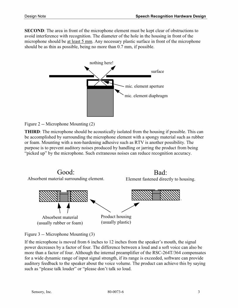
Design Note Speech Recognition Hardware Design
Sensory, Inc. 80-0073-6 3
SECOND: The area in front of the microphone element must be kept clear of obstructions toavoid interference with recognition. The diameter of the hole in the housing in front of themicrophone should be at least 5 mm. Any necessary plastic surface in front of the microphoneshould be as thin as possible, being no more than 0.7 mm, if possible.
nothing here!
surface
mic. element diaphragm
mic. element aperture
Figure 2 -- Microphone Mounting (2)
THIRD: The microphone should be acoustically isolated from the housing if possible. This canbe accomplished by surrounding the microphone element with a spongy material such as rubberor foam. Mounting with a non-hardening adhesive such as RTV is another possibility. Thepurpose is to prevent auditory noises produced by handling or jarring the product from being“picked up” by the microphone. Such extraneous noises can reduce recognition accuracy.
Good:Absorbent material surrounding element.
Bad:Element fastened directly to housing.
Product housing(usually plastic)
Absorbent material(usually rubber or foam)
Figure 3 -- Microphone Mounting (3)
If the microphone is moved from 6 inches to 12 inches from the speaker’s mouth, the signalpower decreases by a factor of four. The difference between a loud and a soft voice can also bemore than a factor of four. Although the internal preamplifier of the RSC-264T/364 compensatesfor a wide dynamic range of input signal strength, if its range is exceeded, software can provideauditory feedback to the speaker about the voice volume. The product can achieve this by sayingsuch as “please talk louder” or “please don’t talk so loud.

Speech Recognition Hardware Design Design Note
80-0073-6 Sensory, Inc.9-44
Analog DesignThe diagram in Figure 4 shows the microphone input circuit and the required externalcomponents and their connections to the RSC-264T/364 for the internal pre-amplifier circuit.The components for each circuit are listed in Table 1 and Table 2.
Figure 4 -- Diagram for Analog Section
VDD
X1MICROPHONE
C2100uF
R2R*
C30.022uF
R1100
C10.1uF
R347
C50.01uF
C8100uF
R42.7K
C74700pF
C4220pF
C60.1uF
Microphone InputCircuit
Required ExternalComponents
Note: R* should be determined by the application.
AIN
1
AIN
0
AIF
E2
RSC264T/RSC364
AIF
E1
AO
FE1
VR
EF
AO
FE2
AO
FE3
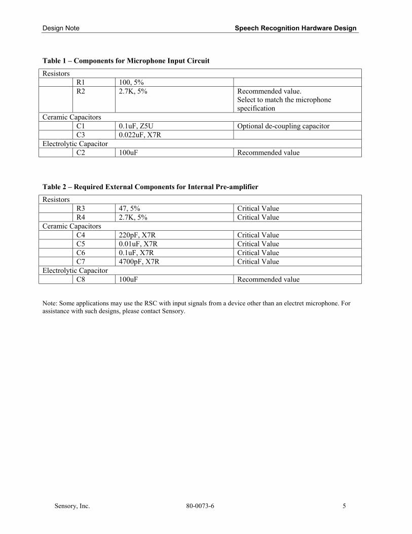
Design Note Speech Recognition Hardware Design
Sensory, Inc. 80-0073-6 5
Table 1 – Components for Microphone Input Circuit
ResistorsR1 100, 5%R2 2.7K, 5% Recommended value.
Select to match the microphonespecification
Ceramic CapacitorsC1 0.1uF, Z5U Optional de-coupling capacitorC3 0.022uF, X7R
Electrolytic CapacitorC2 100uF Recommended value
Table 2 – Required External Components for Internal Pre-amplifier
ResistorsR3 47, 5% Critical ValueR4 2.7K, 5% Critical Value
Ceramic CapacitorsC4 220pF, X7R Critical ValueC5 0.01uF, X7R Critical ValueC6 0.1uF, X7R Critical ValueC7 4700pF, X7R Critical Value
Electrolytic CapacitorC8 100uF Recommended value
Note: Some applications may use the RSC with input signals from a device other than an electret microphone. Forassistance with such designs, please contact Sensory.

Speech Recognition Hardware Design Design Note
80-0073-6 Sensory, Inc.9-66
PCB Design
Analog SectionThe circuit board should be physically organized to allow the largest practical separation of themicrophone input and analog pre-amp circuit from the digital portions of the system. Themicrophone signal is a relatively high impedance signal with an amplitude of only one millivoltor so – digital noise and pickup must be avoided if good recognition accuracy is to be obtained.
Products should use a double-sided (or multi-layer) printed circuit board (PCB) withground plane. The ground plane should cover all analog circuitry area and only connected todigital ground near the RSC device. A star ground system should be employed to ensure that thissingle point is the only connection between the digital and analog grounds. Care should be takento make sure that the analog ground does not carry any digital path current. In order to reducecross talk, the analog and digital circuits should be physically separated as far as is practical.
The reference surface mount PCB layout for the analog section is illustrated in Figure 5.
Note: The ground plane should only be connected to the star of the star ground system,and should not carry any return current.
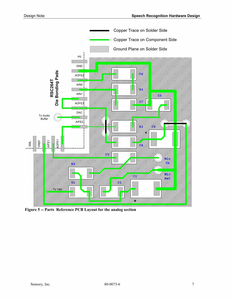
Design Note Speech Recognition Hardware Design
Sensory, Inc. 80-0073-6 7
Figure 5 -- Parts Reference PCB Layout for the analog section
R4
C6
C7
R3
C5
C4
C8
AIFE2
AIFE
1
P0
AOFE2
AIN0
AIN1
AOFE3
DAC
AOFE
1
VREF
XML
GND
C2
C3
R2
R1 C1
RSC
264T
Die
Bon
ding
Pad
s Ground Plane on Solder Side
Copper Trace on Component Side
Copper Trace on Solder Side
MicIn
MicRet
To Vdd
+
+
To AudioBuffer
Speech Recognition Hardware Design Design Note
80-0073-6 Sensory, Inc.9-88
Layout Requirement
Proper layout techniques should be applied not just to the analog section of the PCB, but to theentire PCB layout, including the digital section.
De-coupling CapacitorsA 0.1 µF bypass capacitor should be installed immediately next to each digital IC andnear the VDD pins of the RSC chip. The bypass capacitors should be a monolithicceramic type, rated at 50 volts. If a three-terminal voltage regulator (such as a 7805) isused, Aluminum electrolytic or Tantalum capacitors should be connected close to theregulator between the output pin and ground, and also the input pin and ground.
Data and Address BusThe data lines should be as wide as possible to reduce impedance. The bi-directionalnature of data lines causes large instantaneous currents to get switched around. Withinductive loading, these currents can cause data lines to ring and generate large switchingspikes. Although these spikes and the ringing will have dampened when the data issampled, they could affect the operation of other devices connected to the same bus.
Traces for the data and address line should be routed for the minimal length - makethem as short as possible.
The address, strobe and control signals are outputs of the RSC-264T/364 and have anominal capacitance; their trace widths and length aren’t critical, with a preferred widthof more than 0.012”. These traces can be made around the power traces and the data linetraces, but should avoid analog traces.
Locating and Mounting Interactive Speech ICsSome Interactive Speech ICs are available in packaged form or as bare die. Bare die may be wirebonded directly to the main PCB or, in some cases, may be bonded to a separate chip-on-board(COB) circuit board. In production this COB assembly may be functionally tested, then attachedto the main board as a working module.
There are several methods of attaching the COB to the main board, and a careful choice shouldbe made by the designer. Since cost is always a consideration, COB boards may often bedesigned as single-sided PCBs.
The simplest way of attaching a single-sided COB to a main board is to lay it, chip side up, onthe main board and make solder bridges from the main board up along the thickness of the COBto the electrical contacts on the top of the COB board. However, in production this is not areliable technique.
A second technique is to use wires or pins to connect thru-holes between the main board and theCOB. This reliable technique may be more time consuming.
Design Note Speech Recognition Hardware Design
Sensory, Inc. 80-0073-6 9
A third technique is to put a hole in the main board at the center of the COB location and tomount the COB to the main board UPSIDE DOWN, that is, with the chip facing down into thehole. Then the COB and main boards may be soldered together. In this case, the orientation ofthe signal leads of the RSC-264T/364 is different from that of the other arrangements.
A fourth technique is to put a slot in the main board that is the same width as the thickness as theCOB, and the same length as the COB. The COB can then be mounted perpendicular to the mainboard, and the pads soldered together. This arrangement offers dimensional advantages incertain applications.
All RSC’s in QFP packages are shipped in dry-packed trays, and meet JEDEC level-3 moisturesensitivity standards. Level-3 specifies that once the bag has been opened, the devices should beboard mounted within 168 hours (1 week). If not, they must be re-baked at 125C for 24 hours.Profiling of the IR-Reflow ovens should be carefully monitored, with settings established inaccordance with JEDEC standards.
Circuit Verification Procedure
ProcedureAfter completing the hardware design, the product’s speech recognition performance should becarefully verified. Sensory has developed a software utility located in the subdirectory of theDeveloper Kit “\DKxxx\supplmnt\amptest\”. If you do not have the program, please contactSensory Technical Support. These tests should be performed on an exact sample of the hardwarethat will be used in production, prior to volume production. The programs should beprogrammed into an EPROM or FLASH (if possible) to avoid noise introduced by a ROMemulator. These tests can also be performed on a sampling of production units to test theconsistency of the production hardware. Sensory recommends that all customers completethe following tests.
REQUIRED EQUIPMENT: Sine wave OscillatorOscilloscope
REQUIRED PROGRAM: 264Noise for RSC-264T364Noise for RSC-364
Speech Recognition Hardware Design Design Note
80-0073-6 Sensory, Inc.9-1010
Description of Test ProgramAt power up this program cycles, repeatedly measuring the noise and synthesizing the noisevalue every few seconds. It requires a speaker and microphone, but it does not require any otherspecial circuitry.
ProcedureInstall the EPROM or OTP with “Noise” for the RSC-264T or “364Noise” for the RSC-364program onto the board, and power up the board without the microphone connected.
A. Amplifier Noise Test
1. DC Bias VoltageCheck the DC bias voltage at AOFE2. It should be ½ of VDD.
2. Noise at AOFE2Check the noise (about 1MHz) with an oscilloscope at AOFE2. It should be less than100mVp-p. If the noise is greater than 100mVp-p, install a 1000pF capacitor fromAOFE1 to ground. If this is not adequate for decreasing the high frequency noise,contact Sensory.
3. Noise ValueRecord the noise value synthesized by the “264Noise” program. If the average valueis less than 5, the design is good.
B. Microphone Gain TestIf the board passed the noise check, proceed with Microphone gain setting.
1. Noise Value with Microphone ConnectedConnect the microphone. IN A VERY QUIET ROOM, the noise value synthesizedshould be somewhat larger than it was without the microphone, typically a valuearound 7 to 12.. If so, it is a well-designed system.
2. Adjusting Microphone GainIf the noise with microphone connected is not larger than measured without, themicrophone gain is probably too low. The gain can be increased by increasing theresistance of the microphone load, which is nominally 2.7 Kohms. If this resistanceis increased too much, the gain will actually decrease.
For typical electret microphones, the maximum value of this resistance is about 10K Ohms.
If the system noise with the microphone connected is not greater than with themicrophone input floating, and if the microphone resistance is 10K, please contactSensory for additional assistance.
The following table represents the microphone gain as a function of the microphoneresistance, for a particular microphone. Measurements were taken by putting a
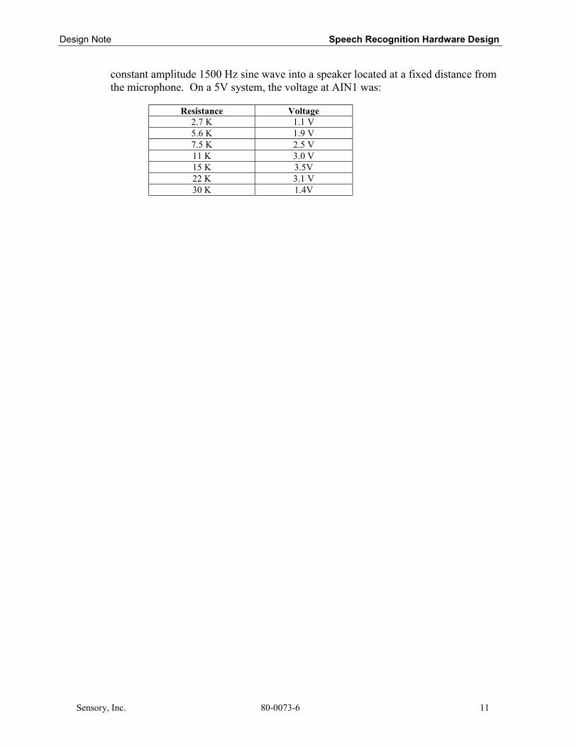
Design Note Speech Recognition Hardware Design
Sensory, Inc. 80-0073-6 11
constant amplitude 1500 Hz sine wave into a speaker located at a fixed distance fromthe microphone. On a 5V system, the voltage at AIN1 was:
Resistance Voltage2.7 K 1.1 V5.6 K 1.9 V7.5 K 2.5 V11 K 3.0 V15 K 3.5V22 K 3.1 V30 K 1.4V
Speech Recognition Hardware Design Design Note
521 East Weddell DriveSunnyvale, CA 94089
TEL: (408) 744-9000FAX: (408)744-1299
IMPORTANT NOTICEReasonable efforts have been made to verify theaccuracy of information contained herein, however noguarantee can be made of accuracy or applicability.Sensory reserves the right to change any specificationor description contained herein.
12 80-0073-6 Sensory, Inc.
Design NoteMemory Requirements
Sensory, Inc 80-0081-2 1
Memory Requirements
This document outlines the memory requirements for each of Sensory’s speech and audiocapabilities. Examples of hypothetical applications are provided to give developers a betterunderstanding of the memory requirements for different combinations of speech technologies.
Memory Usage on the RSC-300/364The RSC-364 has two types of on-chip memory, ROM and RAM. (The RSC-300 is a ROM-lessversion of the RSC-364). ROM is used for five purposes: control code, technology code,speaker-independent speech recognition weights, speech synthesis data, and music synthesisdata. The on-chip RAM has two primary functions: to store information (like speaker-dependentpasswords) and to provide scratch pad memory while performing its normal functions. Off-chip,the RSC-300/364 can also address ROM and a variety of read/write memories (e.g., SRAM,Flash, EEPROM).
ROMThe RSC-364 has 64 kilobytes (kB) of ROM on-chip and can address (use) a virtually unlimitedamount of off-chip (additional) ROM.
ROM is used for a variety of functions:1) Control Code. This refers to the set of instructions that control the product (e.g.,
when the chip hears Red, flash the Red light). This takes about 2kB for a modestapplication but could take well over 10kB in a complex application. Examples givenlater in this document assume a modest use of 4kB for control code.
2) Technology Code. This refers to the set of instructions that control the speech andaudio technologies. Memory requirements for each desired technology are outlinedon the following page. Some features, such as record and playback require off-chipRAM for data storage.
3) Speech Recognition and Speech Synthesis. Aside from memory requirements forthe technology code, there are additional ROM requirements for speech recognitionsets and speech synthesis. ROM requirements are outlined in Section 4 of thisdocument.
4) Four-Voice Music Synthesis and Sound Effects. For four-voice music synthesis,memory requirements range from 5-10 kilobytes per instrument plus 100 bytes persecond of music. ROM requirements for sound effects range from 20 bytes (a simplebeep) to 5,000 bytes (an explosion) depending on the complexity of the sound effects.
Memory allotment on the RSC-364 is flexible. The customer can trade off memory usagebetween recognition sets, synthesis, music, or special applications depending on which features

Memory Requirements Design Note
2 80-0081-2 Sensory, Inc.
are most important to their product. If the desired features will not fit in the on-chip ROM, thecustomer can use an RSC-364 and off-chip ROM.
ROM Requirements - Technology CodeThis section outlines the Read Only Memory (ROM) required to use the speech and audiotechnologies available with the RSC-300/364 and Sensory Speech 6.0 Technology. Note thatother RSC chips have different memory maps. These technologies are implemented by using oneor more of the technology modules provided in the RSC-364 Development Kit software library.The following table lists each technology module, a brief description of its function, its code size(in kilobytes), and which technologies it is used by. For example, an application using Speaker-Independent Recognition and Speaker-Dependent Recognition will only require a total of 15.5kilobytes of memory (Pattern Generation and Fixed-Point Math are only included once). Theoptional technology modules listed in the bottom table can be used with the identified Sensorytechnologies. For applications using multiple technologies, it is only necessary to includeeach technology module once. Note that some features, such as record and playback, mayalso require off-chip RAM.
TechnologyModule Description
ApproxSize(kB) SI SD SV DRT WS RP Talk Music TTone
Patgen Pattern Generation 8.0 √ √ √ √ √
SI Speaker-Independent 1.7 √ √
SD Speaker-Dependent 2.5 √ √ √ √
SV Speaker Verification 0.3 √
DRT Dual RecognitionTechnology 0.9 √
WS Wordspot 2.6 √
RP Record and Playback 7.41 √1
Talk Speech Synthesis 3.4 √
Music Music Synthesis5 1.7 √5
TTone Touch-tone Synthesis 0.6 √
Math(1) Integer Math 0.8 √ √ √ √ √ √ √ √
Math(2) Floating-point Math 2.1 √ √ √ √
Total Sizes 12.6 11.3 13.7 20.0 13.9 10.3 4.2 2.5 0.6
Optional Technologies
RPSimultaneous Record
and PatternGeneration
8.0 (√6) (√6) (√6) (√6) (√6)
CL2 Continuous Listening 0.3 (√)
SEEP3 Sample SerialEEPROM 1.1 (√) (√)
Flash4 Sample Flash RAM 0.8 (√) (√) (√) (√)RS232 RS232 drivers 0.3
DRT DigitsWeights DRT Digits weightset 4.0 (√)
SI DigitsWeights
Speaker Independentweightset 4.3 (√) (√)
Design Note Memory Requirements
Sensory, Inc. 80-0081-2 3
1. Size of Record and Playback code can be reduced if 3-bit and/or 2-bit compression is not used. Add Patgen sizeif thesholding is used.
2. Continuous Listening specified for Speaker-Independent Recognition only.3. Serial EEPROM is optional for Speaker-Dependent Recognition, fast digits DRT, or Speaker Verification
technologies.4. Flash RAM code optional for Record and Playback, Speaker-Dependent Recognition, fast digits DRT, Speaker
Verification and Speaker Adaptive technologies.5. Music Synthesis also requires music notes and the data, which can be as much as 50kB.6. Simultaneous Pattern Generation and recording is optional on the RSC-300/364.
ROM Requirements-Speech Recognition and Synthesis
Speaker-Independent Recognition 1.5-5 kilobytes per setSpeech Synthesis 500-1500 bytes per wordMusic Synthesis 5-10 kilobytes per instrument plus 100 bytes per second
For each speaker-independent recognition set (up to 10 words per set), there is a 2-5kB memoryrequirement. The size of the set (i.e., 2 words vs. 8 words) will have a small effect on ROMusage. Speaker-dependent recognition and the password feature both require off-chip memory(~100 Bytes / word).
For estimation purposes, we generally use .5 kBytes per word (8,000 bits per second of speech,one-half second per word). This will changed depending on the speech quality desired.
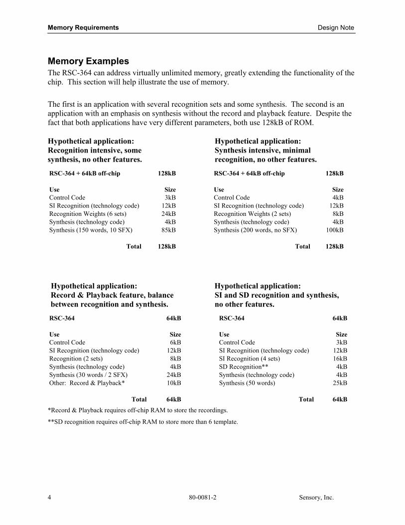
Memory Requirements Design Note
80-0081-2 Sensory, Inc.4
Memory ExamplesThe RSC-364 can address virtually unlimited memory, greatly extending the functionality of thechip. This section will help illustrate the use of memory.
The first is an application with several recognition sets and some synthesis. The second is anapplication with an emphasis on synthesis without the record and playback feature. Despite thefact that both applications have very different parameters, both use 128kB of ROM.
Hypothetical application:Recognition intensive, somesynthesis, no other features.
Hypothetical application:Synthesis intensive, minimalrecognition, no other features.
RSC-364 + 64kB off-chip 128kB RSC-364 + 64kB off-chip 128kB
Use Size Use SizeControl Code 3kB Control Code 4kBSI Recognition (technology code) 12kB SI Recognition (technology code) 12kBRecognition Weights (6 sets) 24kB Recognition Weights (2 sets) 8kBSynthesis (technology code) 4kB Synthesis (technology code) 4kBSynthesis (150 words, 10 SFX) 85kB Synthesis (200 words, no SFX) 100kB
Total 128kB Total 128kB
Hypothetical application:Record & Playback feature, balancebetween recognition and synthesis.
Hypothetical application:SI and SD recognition and synthesis,no other features.
RSC-364 64kB RSC-364 64kB
Use Size Use SizeControl Code 6kB Control Code 3kBSI Recognition (technology code) 12kB SI Recognition (technology code) 12kBRecognition (2 sets) 8kB SI Recognition (4 sets) 16kBSynthesis (technology code) 4kB SD Recognition** 4kBSynthesis (30 words / 2 SFX) 24kB Synthesis (technology code) 4kBOther: Record & Playback* 10kB Synthesis (50 words) 25kB
Total 64kB Total 64kB*Record & Playback requires off-chip RAM to store the recordings.
**SD recognition requires off-chip RAM to store more than 6 template.
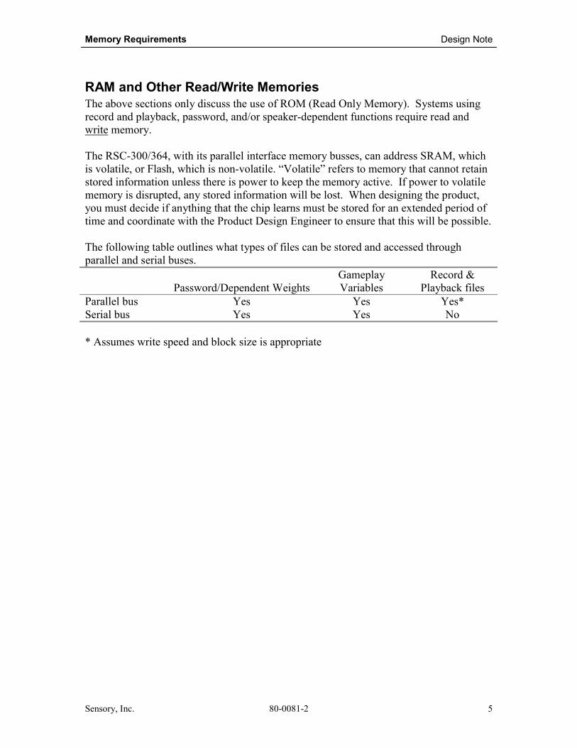
Memory Requirements Design Note
Sensory, Inc. 80-0081-2 5
RAM and Other Read/Write MemoriesThe above sections only discuss the use of ROM (Read Only Memory). Systems usingrecord and playback, password, and/or speaker-dependent functions require read andwrite memory.
The RSC-300/364, with its parallel interface memory busses, can address SRAM, whichis volatile, or Flash, which is non-volatile. “Volatile” refers to memory that cannot retainstored information unless there is power to keep the memory active. If power to volatilememory is disrupted, any stored information will be lost. When designing the product,you must decide if anything that the chip learns must be stored for an extended period oftime and coordinate with the Product Design Engineer to ensure that this will be possible.
The following table outlines what types of files can be stored and accessed throughparallel and serial buses.
Password/Dependent WeightsGameplayVariables
Record &Playback files
Parallel bus Yes Yes Yes*Serial bus Yes Yes No
* Assumes write speed and block size is appropriate

Memory Requirements Design Note
80-0081-2 Sensory, Inc.6
521 East Weddell DriveSunnyvale, CA 94089
TEL: (408) 744-9000FAX: (408)744-1299
IMPORTANT NOTICEReasonable efforts have been made to verify theaccuracy of information contained herein, however noguarantee can be made of accuracy or applicability.Sensory reserves the right to change any specificationor description contained herein.
Application NoteQuick Synthesis Instructions
Sensory, Inc. 80-0186-1 1
Quick Synthesis Instructions
Overview
The Sensory Quick Synthesis Tool is designed to help create and manage speechsynthesis for Sensory RSC microcontroller applications. It can be done quickly (within15 minutes) and without the use of a Sensory linguist. Audio files created with QuickSynthesis will have somewhat lower quality sound and will require more memory thanthose created by Sensory. Quick Synthesis is often used to generate speech synthesis forprototypes or moderate volume production, where development time and cost must beminimized. Once a product goes to production, Sensory-processed files can be generatedto yield the highest audio quality, while minimizing the amount of required memory.
This tool supports all RSC series processors, as well as Sensory’s Voice Extreme™ASSP. It has been tested on Win95/98 platforms only.
InstallationRun setup.exe and follow the installation instructions. The default installation folderis C:\Program Files\QuickSynthesis. A program group will be installed in yourWindows Start menu.
Initial setupThe first time you run Quick Synthesis you will need to indicate where certain filesare located. The first file is optional, the second is mandatory. Pull down the “Files”menu and select the “Preferences” option to set these program defaults.
1. If you have a preferred WAV file editor, you can indicate the path andfilename for it. Click on the top “Set Path” button and navigate to the folderand executable file for this function.
2. You will need to indicate where the file “quicksyn.exe” is located in order tobuild speech synthesis files. Click on the bottom “Set Path” button andnavigate to where the Sensory Quick Synthesis GUI has been installed. Clickon “quicksyn.exe” and press “Save”.

Quick Synthesis Instructions Application Note
2 80-0186-1 Sensory, Inc.
Features• .WAV file list: This list box shows all the .WAV files that have been added to
this project. If you select a file and then press the right-button on your mouse, apop-up menu will be displayed which will allow you to play or edit this file.
• Add button: Use this button to add .WAV files to your project. A dialog box willbe opened to allow you to locate and select files. Multiple selections in a folderare allowed. The format of the .WAV files must be mono, 22050 samples/second,and 16 bits/sample. If a selected file does not conform to this format, and errormessage will be generated and the file will not be included. Open up the file inyour preferred .WAV editor and reformat the files to the correct specifications.
• Move Up/Down button: Use these buttons to organize the .WAV files in yourproject. Multiple files may be moved up or down.
• Remove button: Use this button to remove .WAV files from your project. Youwill be prompted to confirm all removals.
• Output File: Select the output file that will be created during the build process.After a build, six primary output files will be created:1. <output>.mnv – This is the raw PCM output data.2. <output>.a – This is a source file which may be assembled with the Sensory
Assembler, SASM2 to create linkable object files for an application3. <output>.bin – This is a executable file which may be downloaded into a
Sensory demo unit and will allow you to listen to each speech synthesis file toinsure it is of good enough quality.
4. <output>.txt – This is a text file of all the .WAV files which were used in thisproject. Note that this file does not include subdirectory folder names, just thefile names in Windows 8.3 format.

Application Note Quick Synthesis Instructions
Sensory, Inc. 80-0186-1 3
5. <output>.vpi – This file may be added to an assembly language file to provideprogram labels for the CallTalkXXX macros.
6. <output>.voc – This file is useful if you need to have the Sensory Linguisticsstaff further compress the speech synthesis.
• Platform: Select the format for the output files here. The first two options (codespace, data space) are for RSC assembly language applications. The third option(Voice Extreme) is for Voice Extreme™ applications.
• Compression: Select the amount of compression you wish to apply to the speechsynthesis. The compression ratios are approximately as follows:2-Bit: 2700 bytes/second3-Bit: 3400 bytes/second4-Bit: 4100 bytes/secondThe compression level chosen will depend on the available memory for speechsynthesis data and the desired speech quality. If, during the build process, theprogram calculates that the <output>.mnv file will exceed 64Kbytes, it willinform you of this and allow you to abort or proceed anyway with the build.
• Add Silences: Selecting this option will add ten predefined silences to the outputfiles. The silence durations are as follows: 20ms, 40ms, 75ms, 100ms, 160ms,200ms, 400ms, 800ms, 1600ms, 3200ms. This will add approximately 50 bytes tothe <output>.mnv file
• Save Temporary Files: This option will cause some temporary files that arecreated during the build process to be saved. If this is selected, then for each.WAV file in the project a .RAW and .VSF file will also be created. Unless youare planning to have the Sensory Linguists further compress the speech synthesisfiles, these will most likely not be needed.
• Label: This is the label which will be used in the final assembly or VoiceExtreme application to refer to the starting address of the speech synthesis file.
• Build: This is the button that causes the speech synthesis files to be created.• File Menu:
• New: Create a new speech synthesis project• Open: Open a speech synthesis project• Save: Save a speech synthesis project• Save as: Save a speech synthesis project under a different name• Preferences: See “Setup” instructions above• Exit: Goodnight.
Quick Synthesis Instructions Application Note
4 80-0186-1 Sensory, Inc.
Creating a Quick Synthesis Project
When creating a Quick Synthesis Project, there are a few things you need to keep inmind:
• Keep in mind that each word will be synthesized separately, so you need tothink about the ways that you will concatenate the phrases of the finalsynthesis. Generally, words that you use at the beginning of a sentence cannotbe reused at the end without sounding choppy or out of place. Carefulplanning and recording of the word use can sometimes allow you to reusewords in this manner (for example digits), but you will probably have torecord each such word twice.
• Any editing or changing of a .WAV file must be done in an editor before youbegin the processing. There is no way to change the sounds after you start.You also need to make sure that you change the format of any .WAV file notin 22050 Hz, 16-bit, mono format.
• The waveform amplitude should be adjusted to have an amplitude range ofapproximately 16-bits (+/- 32,767). In CoolEdit this is accomplished bynormalizing to 100% before saving.
• You need to do the recording in a quiet area to reduce the need for editing.Background noise will deteriorate the quality of the final compression.
• When selecting the files for your project, make sure to trim any backgroundnoise before and after the utterance. This “silence” will add to your memoryallocation and give you extra pauses in the concatenation of your phrases.
• A .a (sentence) table is not created in this process. If you require such a tablefor your project, a Sensory linguist should be able to create this for you.
Here is a step-by-step procedure for creating your synthesis files.
• Go to “File” then “New”• Click on the “Add” button and locate your files• Select the files you would like to add (multiple files can be added) and click
OK• Make sure that none of your files have filenames of more than 8 characters
• Put the files in the order you would like them listed (alpha-numeric order isusually best).
• Decide if you want to add silences and/or save your temporary files.• Select your platform and compression preferences.
• You will use “code” for most of your projects, unless you know for surethat you will be using Voice Extreme™ or have your synthesis in dataspace memory.
Application Note Quick Synthesis Instructions
Sensory, Inc. 80-0186-1 5
• 4-bit compression will take up the most space, but it will give you the bestquality synthesis. A good approximation for 2-bit memory space is that12 seconds of sound at 2-bit compression will use 32K of memory.
• Choose a label for your project.• Choose your output file. Then name for the .MNV file should be the same as
your label.• Click “Build”.
• You will be prompted at this time to save your project. Click “yes” andyou will be prompted to name a .QSP file. Name this file the same as the.MNV file and the label.
Your files will then begin building. This process can take 5-15 minutes, depending onthe size and number of the files, and your computer’s speed.
For the latest updates to this and other Sensory products, check out our website atwww.VoiceActivation.com. For technical assistance, please send email [email protected].
Quick Synthesis Instructions Application Note
6 80-0186-1 Sensory, Inc.
521 East Weddell DriveSunnyvale, CA 94089
TEL: (408) 744-9000FAX: (408)744-1299
IMPORTANT NOTICEReasonable efforts have been made to verify theaccuracy of information contained herein, however noguarantee can be made of accuracy or applicability.Sensory reserves the right to change any specificationor description contained herein.
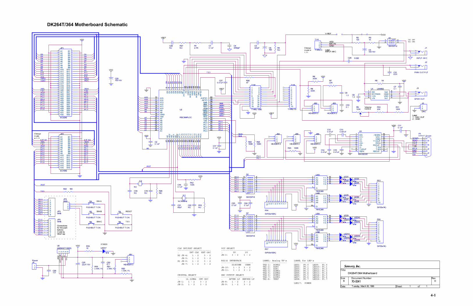
70-0041 D
Sensory, Inc.
B
1 1Tuesday, March 30, 1999
Titl e
Size Document Number Rev
Date: Sheet of
VDD
VDD
VDD
VDD
VDD
VDD
VDD
VDD
VDD
VDD
VREF
VREF
VREF
VDD
VDD
VDD
VDD
VDD
D7D6
A14
A12
D1 D2 D3 D4 D5D0
A15
A13
A11A10A9A8
A7A6A5A4A3A2A1
P1.7
P1.6
P1.5
P1.4
P1.3
P1.2
P1.1
P1.0
P0.7
P0.1P0.2P0.3P0.4
/XML/XMHPDN/WRD/RDD/WRC/RDC
D1D3D5D7
A3A5
A13
P0.5P0.7
P1.7
D0D2D4D6
A2A4
A14
/WRC
P0.4
P1.4
A1
A7A9A11
A15
A0
A6A8A10A12
/RDD/RDC
/XMH
PDN
/WRD
/XML
P0.1P0.3
P1.1P1.3P1.5
P0.2
P0.6P1.0P1.2
P1.6
P0.5P0.7
P1.7
P0.4
P1.4
/XMH
PDN
/XML
P0.1P0.3
P1.1P1.3P1.5
P0.2
P0.6P1.0P1.2
P1.6
T E1
T E1
P0.0
P0.0
P0.0
P0.0P0.1P0.2P0.3P0.4P0.5P0.6P0.7
P1.2P1.3P1.4P1.5P1.6P1.7
TE1
P0.0
P0.7
P1.1
P1.5P1.6
P0.1P0.2P0.3P0.4P0.5P0.6
P1.0
P1.2P1.3P1.4
P1.7
DTR
RTSRXD
P0.1
EXT XI2
/RST
/RST
/RST
T E2
/RST
EXT XI1
T E2
A0
T E1
P0.6
P0.5
P0.0
/XML/XMH
P1.1P1.0
SGNDRING
CD
CT S
DSR
R12.7K
C3220pF
C20.1uF
C44700pF R4
NU C5100/16V
R2100
J1
INPUT -MI C
R31K
J3
SPKR OUT
C70.1
R11180K
U1 LM48621234 5
678SD
BYPASS+IN-IN Vo1
VDDGNDVo2
R5 1M
C91.0
R6300K
C81.0
R8300K
R9100K
S1
SW DIP-2
12
43
R1020K
S2
SW DIP-8
12345678
161514131211109
JP4WH3
123
S3
PUSHBUT T ON
S5
PUSHBUT T ON
S8
PUSHBUT T ON
S4
PUSHBUT T ON
S6
PUSHBUT T ON
U4B
74HC240
11131517
19
9753
A1A2A3A4
G
Y1Y2Y3Y4
U4A
74HC240
2468
1
18161412
A1A2A3A4
G
Y1Y2Y3Y4
LED2LED3
LED8
LED4
LED1
LED6LED7
LED5
S7
SW DIP-8
12345678
161514131211109
LED16
U5A
74HC240
2468
1
18161412
A1A2A3A4
G
Y1Y2Y3Y4
LED15
LED13U5B
74HC240
11131517
19
9753
A1A2A3A4
G
Y1Y2Y3Y4
LED14
LED11LED10
LED9
LED12
P19 Pin F D-t ype
594837261
C150.47uF
C120.47uF
C130. 047uF
C110.1uF
C18NU
C2168pF
C19NU
C170.1uF
C140.47uF
Y1
14.318MHz
Y2
NUC160.1uF
C22NU
R12100K
TH1
THRU 3
123
C230.1uF
C240.1uFR15
NU
R22 100
U2
RSC364PLCC
61626364656667681
19
2345678
101112131415161718
20212223
353433 43
44
4950
323130292827
262524
51
60
48474645
9
42414039383736
5958575655545352
AIF
E2DA
CA
OF
E3A
IN1
AIN
0A
OF
E2G
NDP0
P1/
TE
Vdd
D7D6D5D4D3D2D1
A15A14A13A12A11A10A9A8GND
A7A6A5A4
P1.5
P1.6
P1.7
P0.5
P0.4
VddGND
RST
XI1
XO1
XI2
XO2
A0
A1A2A3
RDC
AOFE1
P0.0P0.1P0.2P0.3
D0
P0.6
P0.7
P1.0
P1.1
P1.2
P1.3
P1.4
AIFE1VrefXMLXMHPDN
WRDRDDWRC
C270.01uF
C100.1
JB2
HEADER 3
123
JB3
HEADER 3
123
R722K
JB5
HEADER 3
123
JB4
HEADER 3
123
R23 100K
R24100K
R25100K
J2
PWM OUT PUT
J5
DAC
12
JP3WH8
12345678
JP5WH81
2345678
R17
SIP(9x100K)
12345678910
R14
SIP(9x100K)
12345678910
R13
SIP(9x1K)
12345678910
R16
SIP(9x1K)
12345678910
U3
MAX3222E
234567
14
11
1312
151617181
89 10
C1+V+C1-C2+C2-V-
R1IN
T2IN
R1OUTT1IN
T1OUTGNDVCC
/SHDNEN
T2OUTR2IN R2OUT
JB6
HEADER 3
123
R2647
R27NU
C10.1uF
C28NU
C29 0.022
C6100
R28NU
R182.94K,1%
R212.49K,1% R20
1.00K,1%
C300.1
JB1
HEADER 3
123J4
Power
12
+ C2522uF/10V
R191K LED17
C261.0
TH3
THRU 10
12345678910
JP2
EC16X2A16 B16A15 B15A14 B14A13 B13A12 B12A11 B11A10 B10A9 B9A8 B8A7 B7A6 B6A5 B5A4 B4A3 B3A2 B2A1 B1
JP1
EC32X2A32 B32A31 B31A30 B30A29 B29A28 B28A27 B27A26 B26A25 B25A24 B24A23 B23A22 B22A21 B21A20 B20A19 B19A18 B18A17 B17A16 B16A15 B15A14 B14A13 B13A12 B12A11 B11A10 B10A9 B9A8 B8A7 B7A6 B6A5 B5A4 B4A3 B3A2A1
B2B1
TH2
THRU 10X2
1 23 45 67 89 1011 1213 1415 1617 1819 20
U6LM2941(TO220)
1 2 3 4 5
C20100/16V
C310.01
DAC AMPMIC PWR
VolumeControl
SW-A
SW-B
SW-C
Connectionsfor the pushbuttons made byWireTrap
RESET
T E1
VCC SELECT
DK264T/364 Motherboard
LED1: P0.0LED2: P0.1LED3: P0.2LED4: P0.3LED5: P0.4LED6: P0.5LED7: P0.6LED8: P0.7
LED9: P1.0LED10: P1.1LED11: P1.2LED12: P1.3
LED14: P1.5LED13: P1.4
LED15: P1.6LED16: P1.7
LABEL for LED's
POWER
CRYSTAL SELECT
. 14.32MHz INT OSCJB-1: 1 - 2 3 - 2JB-2: 1 - 2 3 - 2
------------------------
------------------------
-----------------------. 5V 3VJB-3: 3 - 2 1 - 2
CLK INT/EXT SELECT
. INT CLK EXT OSCX2 JB-4: 1 - 2 3 - 2 JB-5: 1 - 2 3 - 2X1 JB-6: 1 - 2 3 - 2 JB-7: 1 - 2 3 - 2
-------------------------
LED17: POWER
DAC OUTPUT SELECT
. AFTER LP BEFORE LPJB-8: 1 - 2 3 - 2JB-9: 1 - 2 3 - 2
------------------------
RS232 INTERFACE------------------------. DISCONN CONNJB-10: 1 - 2 3 - 2JB-11: 1 - 2 3 - 2
LABEL: Analog TP's------------------
TH2-2: AIN0TH2-1: AOFE2
TH2-3: AIN1TH2-4: AOFE3TH2-5: AIFE2TH2-6: AOFE1TH2-7: AIFE1TH2-8: VREF
Label:1 : DAC OUT2 : GND
MIC INGND
VDD
Label:INPUT-MIC
Changem ade in1.11
Changem adein 1.11
V-REF
TXD
ADJ
OFF
/ON
GN
D INO
UT
4-1
DK264T/364 Motherboard Schematic
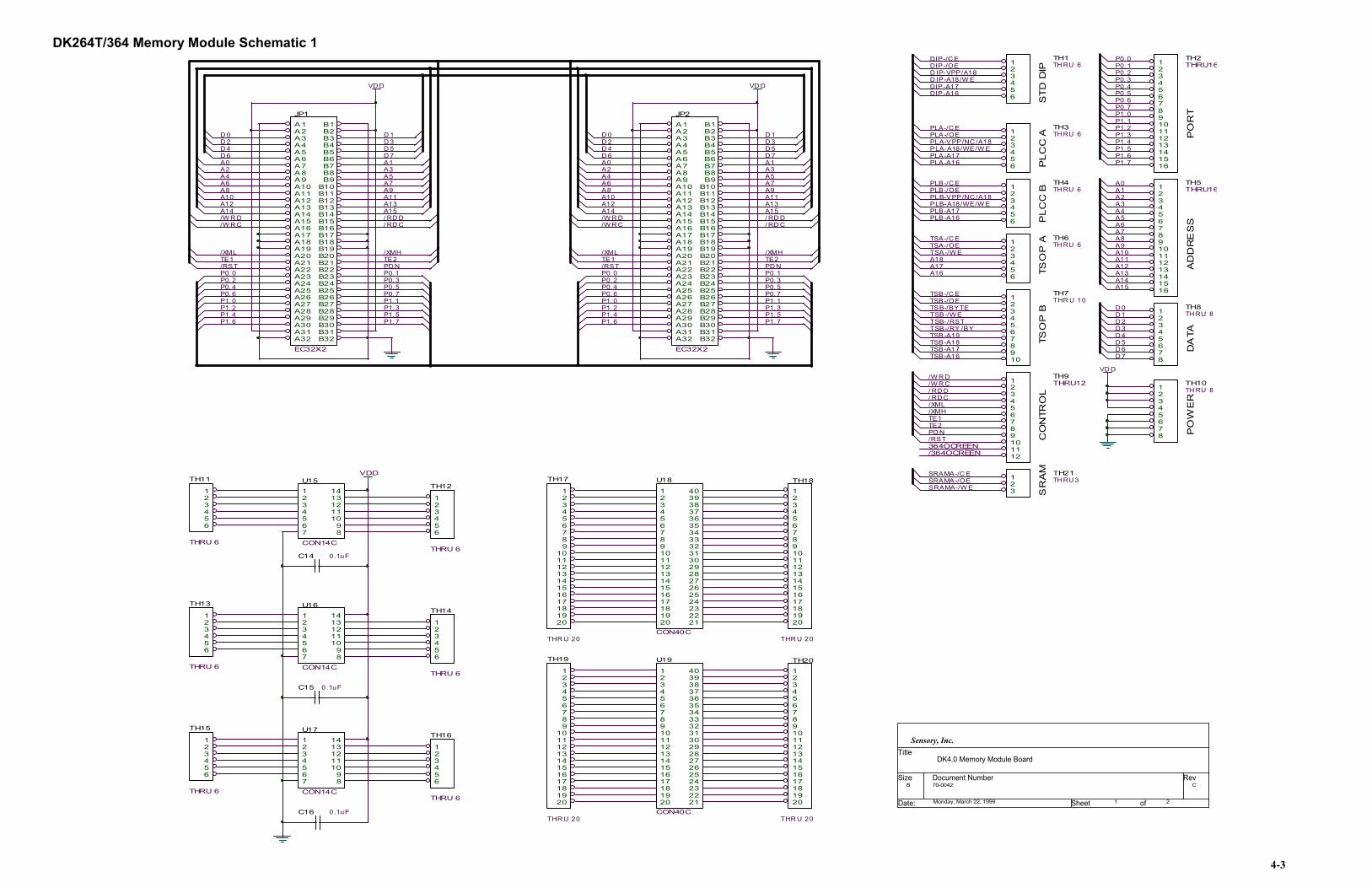
DK264T/364 Memory Module Schematic 1
VDD
VD DVD D
ST
D D
IP
DIP-A16
DIP-/C EDIP-/OE
DIP-A17D IP-A18/W ED IP-VPP/A18 P0. 2
P1. 7
D 7
A14
P0. 7
D 6
P1. 1
P1. 6
A9
/W R D/W R C
P1. 2
D 5
/W R D
/XMH/XML
/RST
A15
/W R C
A7
A12
/ RD DA15
D 3D 4
P0. 3
A4A3
A12
D 1
P0. 3
A5
A8
TE2
P0. 5
D 0
D 5
A6
P1. 4
P0. 4
A0
TE2
P1. 2
A8
A3A2
D 3
A1
P1. 5
P0. 2
P1. 3P1. 1
P0. 1
/XML
P0. 0
/ RD C
P1. 0
/RST
A10
P1. 4P1. 3
P0. 1
D 4
A10
TE1
A4A2
P1. 0
P0. 0
P0. 4
P0. 1
P0. 2
A13A11
A1
P0. 0
P0. 6
D 2
TE1
P0. 5
D 2
/ RD C
D 1
P0. 7
A5
A9
P1. 7
A0
A11
/XMH
P0. 3
/ RD D
PD N
A7
A14
D 0
A13
P0. 6
PD N
P1. 5
D 6
P0. 5
P1. 6
D 7
P0. 4
A6
P0. 6
TH2THRU161
234567
TH11
THRU 6
123456
TH12
THRU 6
123456
C15 0.1uF
C16 0.1uF
U15
CON14C
1234567
1413121110
98
U16
CON14C
1234567
1413121110
98
U17
CON14C
1234567
1413121110
98
TH13
THRU 6
123456
TH14
THRU 6
123456
TH15
THRU 6
123456
TH16
THRU 6
123456
C14 0.1uF
TH18
THR U 20
1234567891011121314151617181920
TH17
THR U 20
123456789
1011121314151617181920
TH20
THR U 20
1234567891011121314151617181920
TH19
THR U 20
123456789
1011121314151617181920
U19
CON40C
1234567891011121314
282726252423222120
1918171615
29303132
35
3334
3637383940
U18
CON40C
1234567891011121314
282726252423222120
1918171615
29303132
35
3334
3637383940
JP1
EC32X2A32 B32A31 B31A30 B30A29 B29A28 B28A27 B27A26 B26A25 B25A24 B24A23 B23A22 B22A21 B21A20 B20A19 B19A18 B18A17 B17A16 B16A15 B15A14 B14A13 B13A12 B12A11 B11A10 B10A9 B9A8 B8A7 B7A6 B6A5 B5A4 B4A3 B3A2A1
B2B1
JP2
EC32X2A32 B32A31 B31A30 B30A29 B29A28 B28A27 B27A26 B26A25 B25A24 B24A23 B23A22 B22A21 B21A20 B20A19 B19A18 B18A17 B17A16 B16A15 B15A14 B14A13 B13A12 B12A11 B11A10 B10A9 B9A8 B8A7 B7A6 B6A5 B5A4 B4A3 B3A2A1
B2B1
TH1TH RU 61
23456
VD D
PL
CC
AP
LC
C B
TSO
P A
TSO
P B
CO
NTR
OL
PO
RT
AD
DR
ES
SD
ATA
PO
WE
R
AM
PLA-VPP/NC /A18
PLB-A17PLB-A16
PLB-A18/WE/W E
PLB-/OEPLB-/C E
PLB-VPP/NC /A18
TSA-/OETSA-/C E
TSA-/W E
A16
A18A17
TSB-/C ETSB-/OE
TSB-/W ETSB-/RSTTSB-/RY /BYTSB-A19TSB-A18TSB-A17TSB-A16
TSB-/BYTE
PLA-A18/WE/W E
PLA-/OE
PLA-A17PLA-A16
PLA-/C E
D 7
D 3
P1. 2
/W R C
A5A4
D 6
P1. 1
TE2
/XMH
/RST
A0
P1. 3
A14
A6
TE1
/XML
/ RD D
/W R D
P1. 0
P1. 5
A12A13
A11
D 1
/ RD C
P1. 4
A8
D 4
P0. 7
A10
PD N
A7
A2
D 2
P1. 7
A15
A9
A3
D 0
P1. 6
D 5
A1
/364OCREEN364OCREEN
SRAMA-/C E
TH3TH RU 61
23456
TH4TH RU 61
23456
TH6TH RU 61
23456
TH7THR U 101
2345678910
8910111213141516
TH5THRU161
2345678910111213141516
TH8TH RU 81
2345678
TH10TH RU 81
2345678
TH9THRU121
23456789101112
TH211
4-3
SRSRAMA-/OE
SRAMA-/W ETH RU 32
3
70-0042 C
Sensory, Inc.
B
1 2Monday, March 22, 1999
Title
Size Document Number Rev
Date: Sheet of
DK4.0 Memory Module Board

DK264T/364 Memory Module Schematic 2
VDD VDD
VDD
VDD
VDD
VDD
VDD
VDD
VDD
VDD
VDD
A[15:0]
D[7:0]
P0.[7:0]
P1.[7:0]
A10
D0
D4D5
PLA-V
PP/N
C/A18
D3
A12
A9
D1
A11
D3
D6
A15
A1
DIP-A
16
A3A2
A5A4
A7
D5
D0
A6
A15
A6
A12A13
A3
A8
D2A0
A5
A11A4
D2
D7
D4
A10D1
D6 A1
A8
A14
A0 A2
A9
A13A7
A13
A12
A0
A5
A2
PLB-A
17
A15
A14
A10
A8
PLB-A
16
A9
D0
A11
D6D4
A1
A7
D1
A3
A6
PLB-/
OE
D2
A4
D5D3
A7
A8
A5
A15
A14
A4
A12
A9A11
A13
A6
D7 D7
DIP-/
CEDIP
-/OE
DIP-A
17DIP
-A18/W
EDIP
-VPP/A
18
PLB-V
PP/N
C/A18
T SB-/OE
PLB-/OE CC13
T SB-/CET SB-/ BYT ET SB-/RST CC28
T SB-A18 CC31T SB-A17T SB-A16
PLA-/
OEPL
A-A17
PLA-A
18/WE
/WE
PLA-A
16
PLB-A16 CC17PLB-A17
PLA-A18/WE/WE
PLA-/OEPLA-/CE
PLA-/
CE
PLB-/OE
P0.0P0.1P0.2P0.3P0.4P0.5P0.6
P1.0P1.1P1.2P1.3P1.4P1.5P1.6P1.7
/WRC
/RDC
/WRD
/RST
P0.7
P0.7
/RDD
SRAMA-/WE CC36SRAMA-/O E CC35SRAMA-/CE CC34
A14
PLB-A18/WE/WE CC15
PLB-A18/WE/WE
T SB-/WE
PLB-/CE
PLB-A
18/WE
/WE
PLB-/CE
PLB-/
CE
DIP-/CEPLA-/CEPLA-/CEPLB-/CE CC12T SA-/CE CC18T SB-/CE CC24SRAMA-/CE
P0.6P0.5
PLB-A17PLB-A16
DAT A-/CE
PLA-A16
PLA-A17
JB1HEADER 3
1 2 3
C10.1uF
U1DIP32
123456789
10111213141516 17
181920212223242526272829303132VPP/A18
A16A15/A14A12A7A6A5A4A3A2A1A0DQ0DQ1DQ2Vss DQ3
DQ4DQ5DQ6DQ7
CEA10OE
A11A9A8
A13A14/(R/W)
A17/VCCA18/WE
Vcc
C40.1uF
U3PLCC3212
1110
98765
13
14 15 16 17 18 19 20
212223242526272829
303132234 1
A0A1A2A3A4A5A6A7
Q0
Q1 Q2 VSS
Q3 Q4 Q5 Q6
Q7/E
A10/G
A11A9A8
A13A14
A17
A18/W
E/WEVC
CA16
A15
A12
VPP/N
C/A18
U4PLCC3212
111098765
13
14 15 16 17 18 19 20
212223242526272829
303132234 1
A0A1A2A3A4A5A6A7
Q0
Q1 Q2 VSS
Q3 Q4 Q5 Q6
Q7/E
A10/G
A11A9A8
A13A14
A17
A18/W
E/WEVC
CA16
A15
A12
VPP/N
C/A18
C20.1uF
U2T SO P32
U8
74VHC244A
2468
11131517
119
181614129753
1A11A21A31A42A12A22A32A4
1G2G
1Y11Y21Y31Y42Y12Y22Y32Y4
U11
74VHC244A
2468
11131517
119
181614129753
1A11A21A31A42A12A22A32A4
1G2G
1Y11Y21Y31Y42Y12Y22Y32Y4
JB4
HEADER 2
12
U10
74VHC244A
2468
11131517
119
1A11A21A31A42A12A22A32A4
1G2G
R1100K
R2100K
C70.1uF
C80.1uF
JP5WH8
12345678
JP3WH8
12345678
JPWH
U6D74VHC04
9 8
U13
74VHC244A
2468
11131517
119
181614129753
1A11A21A31A42A12A22A32A4
1G2G
1Y11Y21Y31Y42Y12Y22Y32Y4
S1
PUSHBUT T ON
R6100
R71K
R5100K
R10100K
R9100K
U6B74VHC04
3 4U9A
74VHC00
1
23
R11100K C11
0.1uF
U9D
74VHC00
12
1311
U9B
74VHC00
4
56
JB6
HEADER 2
12
U6C74VHC04
5 6
U6A74VHC04
1 2
R4100K
R8100K
R1310K x 9
123456789
10
S2
C1 1
48
2
C2
R3100K
R15 100K
R14 100K
32-P IN: 2-128-P IN: 3-2
DIP PLCC A PLCC B
T o run364 dem o,place a shortingblock
Connem adeterm iwires
Boot SW
T o run264 dem o,place a shortingblock
4-4
VDD
VDD
VDD
VDD
VDD
VDD
VDD
RSC[12:0]
CC[40:0]
GND
Vdd
A3A10
A0
D1
D7
TSA-/
OETS
A-/CE
A2A1
D4D3
D0
D2
TSA-/
WE
A16
D5
A18
D6
A17
TSB-/
CETS
B-/OE
TSB-/
RST
TSB-/
RY/BY
TSB-A
19
CC31
TSB-A
18TS
B-A17
TSB-A
16
A15A14A13A12A11A10A9
A8A7A6A5A4A3A2
D7
D6
D5
D4
D3
D2
D1
D0
A0 A1
TSB-/
BYTE
CC26
DIP-/CEDIP-/O E
PLA-/CEPLA-/OE CC7
SCLSDA
A0A1A2A3A4A5A6A7A8A9A10A11A12A13A14
D0D1D2D3D4D5D6D7
SRAMA-/CESRAMA-/O ESRAMA-/WEPLA-A16
PLA-A17
TSB-/
WE
/WRC RSC1
T E2 RSC7
/XMH RSC5
/RST RSC9
T E1 RSC6
/XML RSC4
/RDD RSC2
/WRD RSC0
/RDC RSC3
PDN RSC8
/364OCREEN RSC11364OCREEN RSC10
CC1 DIP-/O ECC2 DIP-A17CC3 DIP-A18/WECC4 DIP-VPP/A18CC5 DIP-A16CC6 PLA-/CECC7 PLA-/OECC8 PLA-A17CC9 PLA-A18/WE/WECC10 PLA-VPP/NC/A18CC11 PLA-A16CC12 PLB-/CECC13 PLB-/OECC14 PLB-A17CC15 PLB-A18/WE/WECC16 PLB-VPP/NC/A18CC17 PLB-A16CC18 T SA-/CE
CC20 T SA-/WECC21 A18CC22 A17CC23 A16CC24 T SB-/CECC25 T SB-/OECC26 T SB-/ BYT ECC27 T SB-/WECC28 T SB-/RSTCC29 T SB-/RY/BYCC30 T SB-A19CC31 T SB-A18CC32 T SB-A17CC33 T SB-A16CC34 SRAMA-/CECC35 SRAMA-/O ECC36 SRAMA-/WE
CC19 T SA-/OE
CC0 DIP-/CE
Vcc
123456789
10111213141516
3231302928272625
2324
222120191817
A11A9A8A13A14A17/WEVCCA18A16A15A12A7A6A5A4
/OEA10/CE
DQ7DQ6DQ5DQ4DQ3
DQ2GND
DQ1DQ0
A0A1A2A3
C30.1uF
U5M29W400T Norm alT SOP
2524232221201918
87654321 48
1716
9101112131415
26272829303132333435363738394041424344454647
A0A1A2A3A4A5A6A7
A8A9A10A11A12A13A14A15 A16
A17NC(A18)
NCNC/WE/RSTNCNCRY/BY
/CEVSS/OED0D8D1D9D2
D10D3
D11VCC
D4D12D5
D13D6
D14D7
D15/A-1VSS
/ BYT E
C50.1uF
181614129753
1Y11Y21Y31Y42Y12Y22Y32Y4
JB2
HEADER 2
12
JB3
HEADER 2
12
U12
24LC65
12345
678
A0A1A2
VSSSDASCLNCVCC
C100.1uF
U6E74VHC04
11 10
U6F74VHC04
13 12
C130.1uF
C120.1uF
43
123
C170.1uF
U14
T C55257DFT L
171615141312111043
282958
2716
1819202223242526
7
21
A0A1A2A3A4A5A6A7A8A9A10A11A12A13A14
CEOEW/R
D0D1D2D3D4D5D6D7
VCC
GND
C18100uF/16V
C19100uF/16V
C90.1uF
U9C
74VHC00
9
108
TSOP A TSOP B
T o use DIP as acode space,place a shortingblock.
T o use PLCC-Aas a codespace, place ashorting block.
ctions bynated.
SRAM-A

223
CHAPTER 10 - SUPPORT
This chapter describes Sensory's RSC-364 Development Kit Support Policyand Limited Warranty.

1. RSC-364 Development Kit Support PolicyIf you have questions about the RSC-364 Development Kit, first look in the provided documentation tofind the answer. If you cannot find the answer, contact Sensory for technical support.
Sensory will provide 5 hours of technical support at no-charge on the Development Kit software andhardware. Additional support may be contracted from Sensory on an hourly basis under mutually agree-able terms and schedules.
Technical support is available via a toll call between 8:30 A.M. and 5:30 P.M. Pacific time, Mondaythrough Friday, excluding holidays. Call (408) 744-9000 and ask for Development Kit support.Technical support is also available via fax or e-mail with a 48-hour turnaround time. Fax: (408) 744-1299, e-mail: [email protected]
2. RSC-364 Development Kit Limited WarrantyThe RSC-364 Development Kit is warranted against defects and workmanship for a period of 90 daysfrom the date of product purchase. Sensory, Inc. will, at its option, either repair or replace a product thatproves to be defective either upon receipt or through normal usage. If a Sensory Development Kit prod-uct has been obsoleted or is no longer in production and deemed non-repairable, Sensory will, at itsoption, provide an equivalent product or system for a nominal fee.
Sensory, Inc. warrants this Development Kit product, when properly installed and used, will execute itsprogrammed instructions. However, Sensory, Inc. does not warrant that the operation of the Product, itsfirmware and software will be uninterrupted or totally error free. The Product must be returned toSensory, Inc. for warranty service within the warranty period to the following address: Sensory, Inc.,521 E. Weddell Drive, Sunnyvale, CA 94089-2164. The Buyer will pay all shipping and other chargesor assessments for the return of the Product to Sensory, Inc.
Limitation of WarrantyThe foregoing warranty shall not apply to defects resulting from maintenance performed by anyoneother than Sensory, Inc., modifications made by Buyer or any third party, Buyer supplied software orinterfacing, misuse, abuse, accident, mishandling, operation outside the environmental specifications forthe Product, or improper setup or maintenance.
Exclusive RemediesThe remedies provided herein are Sensory's sole liability and Buyer's sole and exclusive remedies forbreach of warranty. Sensory shall not be liable for any special, incidental, consequential, direct or indi-rect damages, whether based on contract, tort, or any legal theory. The foregoing warranty is in lieu ofany and all other warranties, whether express, implied, or statutory, including but not limited to war-ranties of merchantability and suitability for a particular purpose.
3. Important NoticesSensory reserves the right to make changes to or to discontinue any productor service identified in this publication at any time without notice for any
224 RSC-364 Development Kit Chapter 10 - Support

reason whatsoever. Sensory does not assume responsibility for use of anycircuitry other than circuitry entirely embodied in a Sensory product.Information contained herein is provided gratuitously and without liability toany user. Reasonable efforts have been made to verify the accuracy of thisinformation but no guarantee whatsoever is given as to the accuracy or as toits applicability to particular uses.
Applications described in this manual are for illustrative purposes only, andSensory makes no warranties or representations that the Interactive SpeechTM
line of products will be suitable for such applications. In every instance, itmust be the responsibility of the user to determine the suitability of the prod-ucts for each application. Sensory products are not authorized for use ascritical components in life support devices or systems.
Sensory conveys no license or title, either expressed or implied, under anypatent, copyright, or mask work right to the Interactive SpeechTM line ofproducts, and Sensory makes no warranties or representations that theInteractive SpeechTM line Interactive SpeechTM of products are free frompatent, copyright, or mask work right infringement, unless otherwise speci-fied. Nothing contained herein shall be construed as a recommendation touse any product in violation of existing patents or other rights of third par-ties. The sale of any Sensory product is subject to all Sensory Terms andConditions of Sales and Sales Policies.
225RSC-364 Development KitChapter 10 - Support
521 E. Weddell DriveSunnyvale, CA 94089TEL: (408) 744-9000 FAX: (408) 744-1299
© 2000 SENSORYALL RIGHTS RESERVED