rst flexi-mux instruction manual
TRANSCRIPT
RST INSTRUMENTS LTD.
RST Flexi-Mux
Instruction Manual
Copyright ©2012 RST Instruments Ltd. All Rights Reserved.
RST Instruments Ltd. 11545 Kingston St., Maple Ridge, B.C. Canada V2X 0Z5 Tel: (604) 540-1100 Fax: (604) 540-1005 Email: [email protected] Website: www.rstinstruments.com
RST Flexi-Mux Instruction Manual
RST Instruments
i
RST Flexi-Mux Instruction Manual
Although all efforts have been made to ensure the accuracy and completeness of the information contained in this document, RST Instruments reserves the right to change the information at any time and assumes no liability for its accuracy.
Product: RST Flexi-Mux Instruction Manual
Document number: ELM0029A RST Flexi-Mux Instruction Manual.doc
Revision: 1.1
Date: March 23, 2012
RST Flexi-Mux Instruction Manual
RST Instruments
ii
TABLE OF CONTENTS
1 OVERVIEW .................................................................................................................. 1
2 FUNCTION ................................................................................................................... 1
3 COMPATIBILITY ............................................................................................................ 3
4 PHYSICAL DESCRIPTION ............................................................................................... 3
4.1 LAYOUT................................................................................................................. 3
4.2 DIMENSIONS .......................................................................................................... 4
4.3 CONNECTION DETAILS ............................................................................................ 4
5 OPERATION ................................................................................................................. 5
5.1 CONTROL TERMINALS ............................................................................................ 5 5.1.1 RESET ............................................................................................................ 6
5.1.2 CLOCK ............................................................................................................ 7 5.1.3 GROUND ......................................................................................................... 7
5.2 DIP SWITCH SETTINGS .......................................................................................... 7
5.3 CONNECTION EXAMPLES ........................................................................................ 9 5.3.1 2-WIRE SERIAL SWITCHING .............................................................................. 9
5.3.2 4-WIRE SERIAL SWITCHING ............................................................................ 10
5.3.3 4-WIRE SWITCHING WITH SEPARATE EXCITATION............................................. 11
5.3.4 8-WIRE SERIES/PARALLEL SWITCHING ............................................................ 12 5.4 DATALOGGER PROGRAMMING ............................................................................... 12
6 SPECIFICATIONS ........................................................................................................ 14
LIST OF FIGURES
Figure 1 – Flexi-Mux Cascading Feature ................................................................................... 2 Figure 2 – Flexi-Mux Layout ....................................................................................................... 3 Figure 3 – Flexi-Mux Dimension ................................................................................................. 4 Figure 4 – Connector Detail ....................................................................................................... 5 Figure 5 – Flexi-Mux to CR10x Datalogger Power/Control Hookup ............................................ 6 Figure 6 – DIP Switch Location .................................................................................................. 7 Figure 7 – DIP Switch Positions ................................................................................................. 8 Figure 8 – Flexi-Mux Connected to a Thermistor String ............................................................. 9 Figure 9 – Flexi-Mux with VW Instruments ................................................................................10 Figure 10 – Flexi-Mux with Biaxial In-Place Inclinometers .........................................................11 Figure 11 – Flexi-Mux wired in Parallel to Switch 8-wires ..........................................................12 Figure 12 – Flexi-Mux Program Example ..................................................................................13
RST Flexi-Mux Instruction Manual
RST Instruments
1
1 OVERVIEW
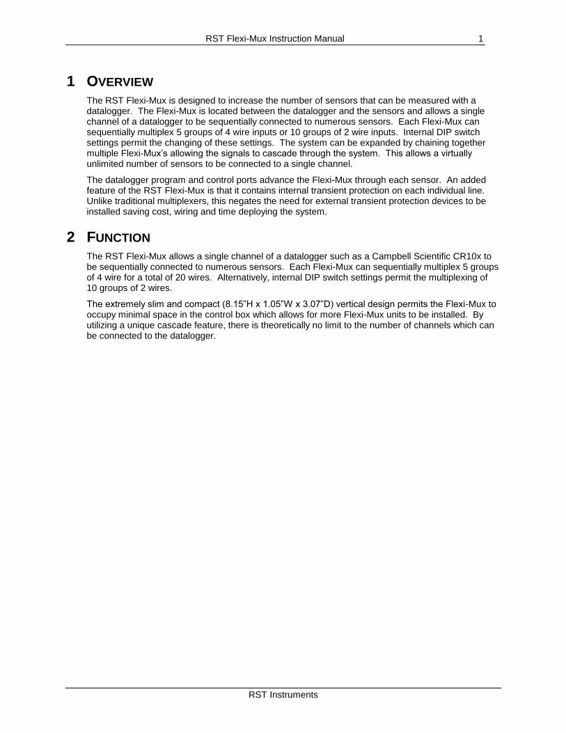
The RST Flexi-Mux is designed to increase the number of sensors that can be measured with a datalogger. The Flexi-Mux is located between the datalogger and the sensors and allows a single channel of a datalogger to be sequentially connected to numerous sensors. Each Flexi-Mux can sequentially multiplex 5 groups of 4 wire inputs or 10 groups of 2 wire inputs. Internal DIP switch settings permit the changing of these settings. The system can be expanded by chaining together multiple Flexi-Mux’s allowing the signals to cascade through the system. This allows a virtually unlimited number of sensors to be connected to a single channel.
The datalogger program and control ports advance the Flexi-Mux through each sensor. An added feature of the RST Flexi-Mux is that it contains internal transient protection on each individual line. Unlike traditional multiplexers, this negates the need for external transient protection devices to be installed saving cost, wiring and time deploying the system.
2 FUNCTION
The RST Flexi-Mux allows a single channel of a datalogger such as a Campbell Scientific CR10x to be sequentially connected to numerous sensors. Each Flexi-Mux can sequentially multiplex 5 groups of 4 wire for a total of 20 wires. Alternatively, internal DIP switch settings permit the multiplexing of 10 groups of 2 wires.
The extremely slim and compact (8.15”H x 1.05”W x 3.07”D) vertical design permits the Flexi-Mux to occupy minimal space in the control box which allows for more Flexi-Mux units to be installed. By utilizing a unique cascade feature, there is theoretically no limit to the number of channels which can be connected to the datalogger.
RST Flexi-Mux Instruction Manual
RST Instruments
2
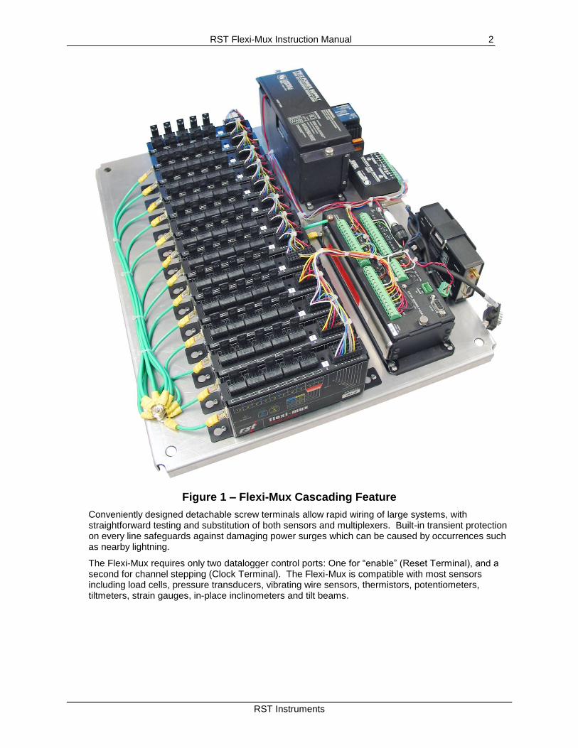
Figure 1 – Flexi-Mux Cascading Feature
Conveniently designed detachable screw terminals allow rapid wiring of large systems, with straightforward testing and substitution of both sensors and multiplexers. Built-in transient protection on every line safeguards against damaging power surges which can be caused by occurrences such as nearby lightning.
The Flexi-Mux requires only two datalogger control ports: One for “enable” (Reset Terminal), and a second for channel stepping (Clock Terminal). The Flexi-Mux is compatible with most sensors including load cells, pressure transducers, vibrating wire sensors, thermistors, potentiometers, tiltmeters, strain gauges, in-place inclinometers and tilt beams.
RST Flexi-Mux Instruction Manual
RST Instruments
3
3 COMPATIBILITY
The Flexi-Mux is compatible with, but not limited to, Campbell’s CR200, CR510, CR10(X), CR23X, CR5000 series dataloggers.
A wide variety of commercially available sensors are supported provided the current maximums are not exceeded on the relay contacts (section 6).
Using a single Flexi-Mux in combination with a Campbell AVW-1 Vibrating Wire Interface, up to 5 RST vibrating wire piezometers can be multiplexed. Cascading each Flexi-Mux permits a theoretically unlimited number of muxes to be chained together. Thus many vibrating wire sensors can be connected to a single vibrating wire interface.
4 PHYSICAL DESCRIPTION
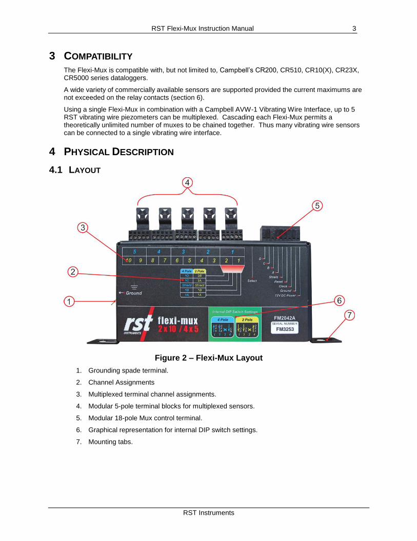
4.1 LAYOUT
Figure 2 – Flexi-Mux Layout
1. Grounding spade terminal.
2. Channel Assignments
3. Multiplexed terminal channel assignments.
4. Modular 5-pole terminal blocks for multiplexed sensors.
5. Modular 18-pole Mux control terminal.
6. Graphical representation for internal DIP switch settings.
7. Mounting tabs.
RST Flexi-Mux Instruction Manual
RST Instruments
4
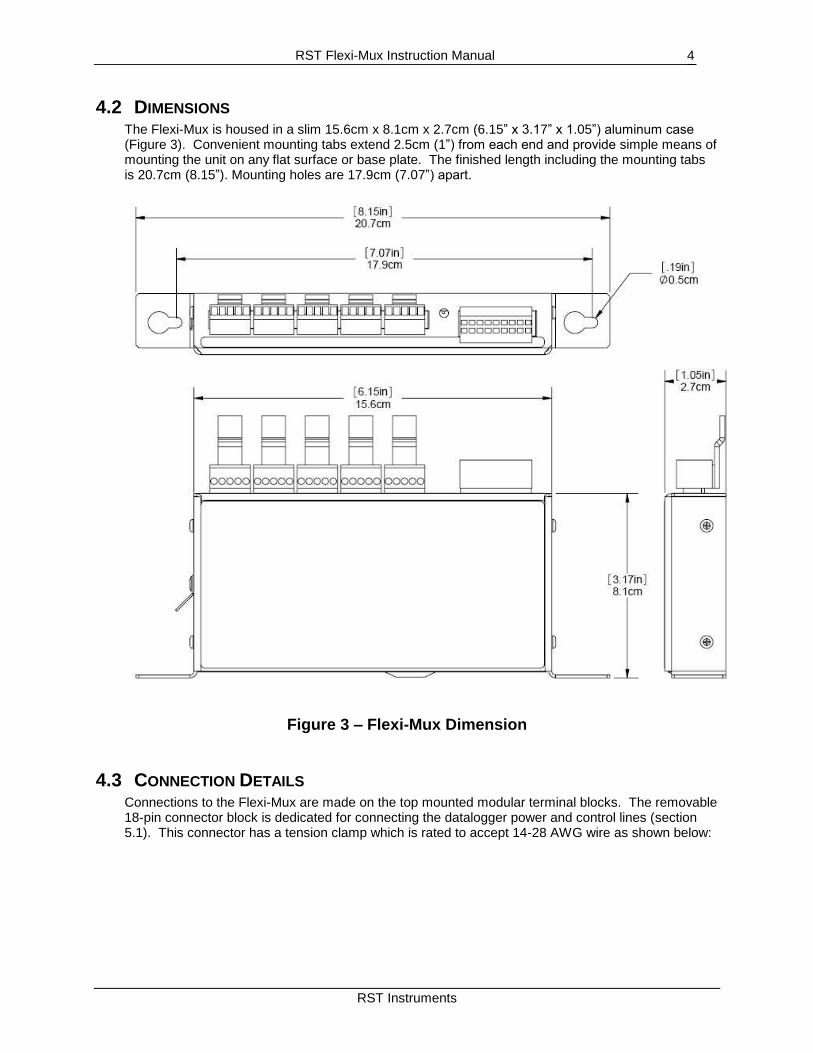
4.2 DIMENSIONS The Flexi-Mux is housed in a slim 15.6cm x 8.1cm x 2.7cm (6.15” x 3.17” x 1.05”) aluminum case (Figure 3). Convenient mounting tabs extend 2.5cm (1”) from each end and provide simple means of mounting the unit on any flat surface or base plate. The finished length including the mounting tabs is 20.7cm (8.15”). Mounting holes are 17.9cm (7.07”) apart.
Figure 3 – Flexi-Mux Dimension
4.3 CONNECTION DETAILS Connections to the Flexi-Mux are made on the top mounted modular terminal blocks. The removable 18-pin connector block is dedicated for connecting the datalogger power and control lines (section 5.1). This connector has a tension clamp which is rated to accept 14-28 AWG wire as shown below:
RST Flexi-Mux Instruction Manual
RST Instruments
5
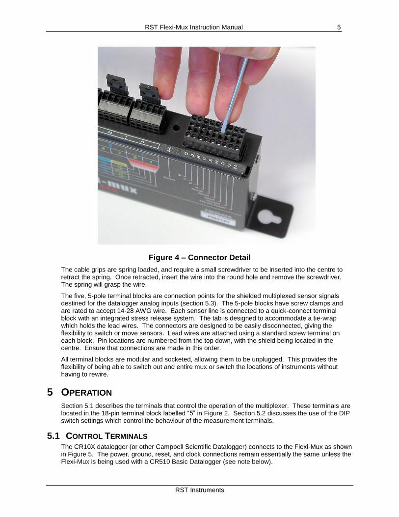
Figure 4 – Connector Detail
The cable grips are spring loaded, and require a small screwdriver to be inserted into the centre to retract the spring. Once retracted, insert the wire into the round hole and remove the screwdriver. The spring will grasp the wire.
The five, 5-pole terminal blocks are connection points for the shielded multiplexed sensor signals destined for the datalogger analog inputs (section 5.3). The 5-pole blocks have screw clamps and are rated to accept 14-28 AWG wire. Each sensor line is connected to a quick-connect terminal block with an integrated stress release system. The tab is designed to accommodate a tie-wrap which holds the lead wires. The connectors are designed to be easily disconnected, giving the flexibility to switch or move sensors. Lead wires are attached using a standard screw terminal on each block. Pin locations are numbered from the top down, with the shield being located in the centre. Ensure that connections are made in this order.
All terminal blocks are modular and socketed, allowing them to be unplugged. This provides the flexibility of being able to switch out and entire mux or switch the locations of instruments without having to rewire.
5 OPERATION
Section 5.1 describes the terminals that control the operation of the multiplexer. These terminals are located in the 18-pin terminal block labelled “5” in Figure 2. Section 5.2 discusses the use of the DIP switch settings which control the behaviour of the measurement terminals.
5.1 CONTROL TERMINALS The CR10X datalogger (or other Campbell Scientific Datalogger) connects to the Flexi-Mux as shown in Figure 5. The power, ground, reset, and clock connections remain essentially the same unless the Flexi-Mux is being used with a CR510 Basic Datalogger (see note below).
RST Flexi-Mux Instruction Manual
RST Instruments
6
12V
DC
Pow
er
Gro
und
Clo
ck
Reset
Shie
ld
12V
G
C1-C8
C1-C8
G
CR10X
Flexi-Mux
Terminal Connector
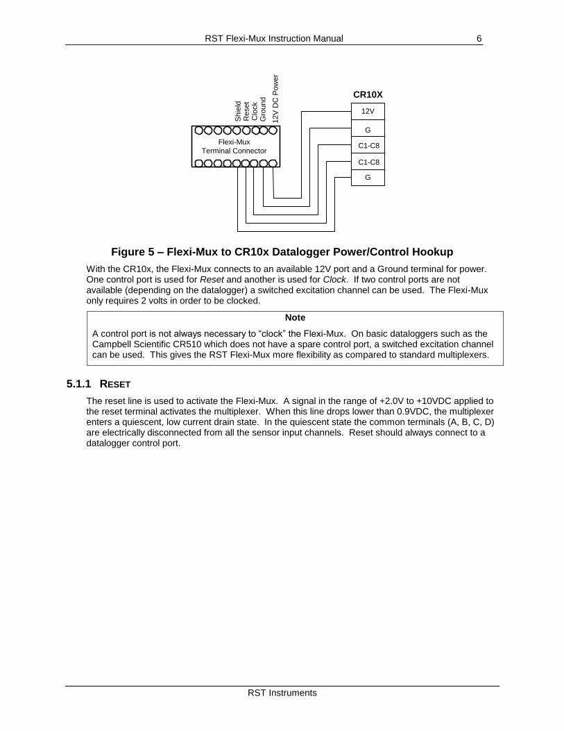
Figure 5 – Flexi-Mux to CR10x Datalogger Power/Control Hookup
With the CR10x, the Flexi-Mux connects to an available 12V port and a Ground terminal for power. One control port is used for Reset and another is used for Clock. If two control ports are not available (depending on the datalogger) a switched excitation channel can be used. The Flexi-Mux only requires 2 volts in order to be clocked.
Note
A control port is not always necessary to “clock” the Flexi-Mux. On basic dataloggers such as the Campbell Scientific CR510 which does not have a spare control port, a switched excitation channel can be used. This gives the RST Flexi-Mux more flexibility as compared to standard multiplexers.
5.1.1 RESET
The reset line is used to activate the Flexi-Mux. A signal in the range of +2.0V to +10VDC applied to the reset terminal activates the multiplexer. When this line drops lower than 0.9VDC, the multiplexer enters a quiescent, low current drain state. In the quiescent state the common terminals (A, B, C, D) are electrically disconnected from all the sensor input channels. Reset should always connect to a datalogger control port.
RST Flexi-Mux Instruction Manual
RST Instruments
7
5.1.2 CLOCK
Pulsing the Flexi-Mux “clock” line high (with “reset” set high) advances the channel. Whether or not the Flexi-Mux advances 2 positions or 4 positions depends on the internal DIP switch settings (section 5.2). When the reset first goes high, the common terminals A, B, C and D are disconnected from all sensor input terminals. With the Flexi-Mux set in the 4-Pole mode, when the first clock pulse arrives the common terminals are switched to connect with the sensor input channel 1 (consists of 5 wires: A, B, C, D and shield). When a second clock pulse arrives the common lines are switched to connect to channel 2. The multiplexer advances along the leading edge of the positive going clock pulse. The voltage level must fall below 1.5VDC and then rise about 2.0VDC to clock the multiplexer. The clock pulse should be at least 1 ms long. A delay (typically 10 to 20 ms) is inserted in the datalogger program between the beginning of the clock pulse and the measurement instruction to ensure sufficient settling time for the relay contacts.
In general, a control port is used to clock the multiplexer. However, switched excitation for the sensors can also be used (as stated in section 5.1). See section 5.3 for more details on datalogger connections with the Flexi-Mux.
If several multiplexers are required, the Flexi-Mux allows a virtually unlimited number of units (limited by cable losses) to be connected in series because the Flexi-Mux boosts the clock and reset signals through its circuitry. Thus no control voltage is lost through the ports. An adequate 12VDC power source must be maintained through each multiplexer for this to function correctly.
5.1.3 GROUND
The Flexi-Mux “ground” terminal is connected to the datalogger power ground.
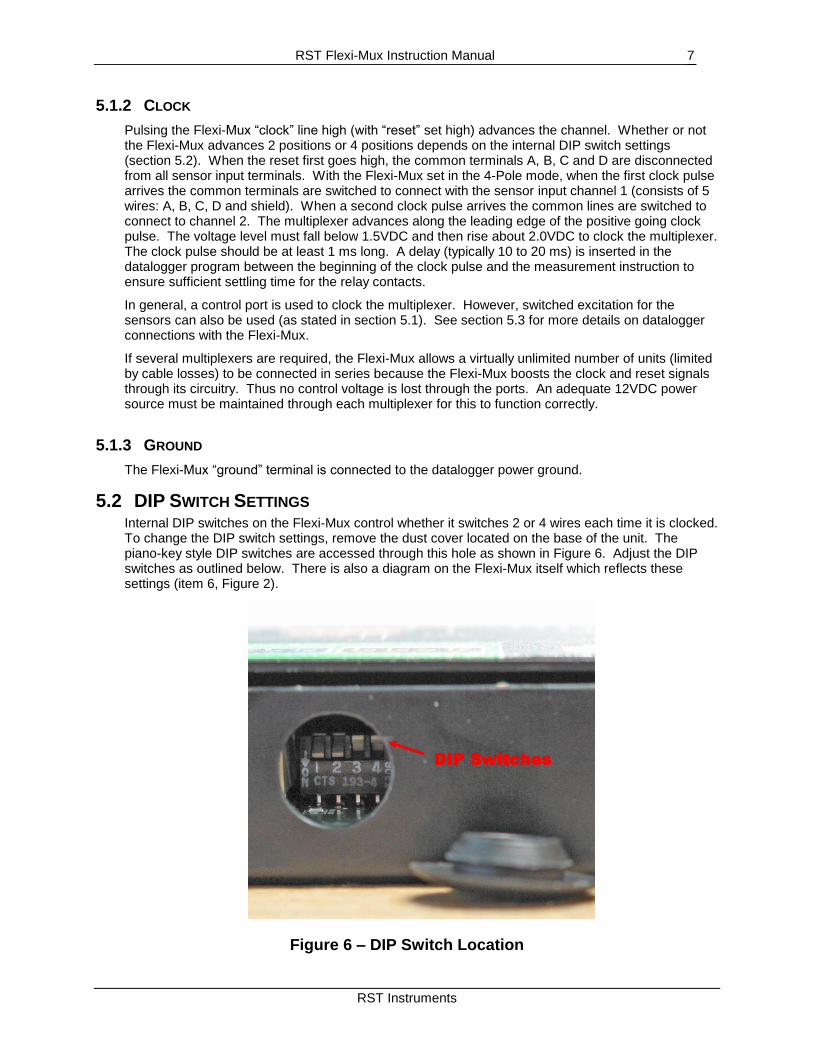
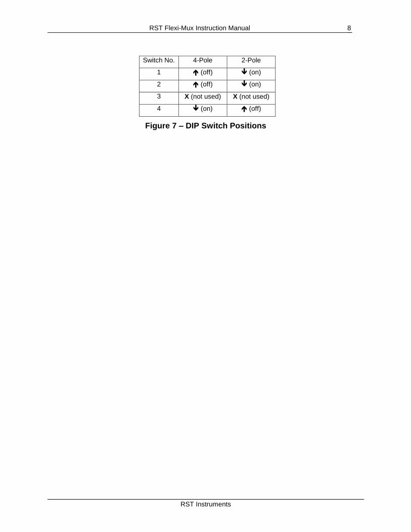
5.2 DIP SWITCH SETTINGS Internal DIP switches on the Flexi-Mux control whether it switches 2 or 4 wires each time it is clocked. To change the DIP switch settings, remove the dust cover located on the base of the unit. The piano-key style DIP switches are accessed through this hole as shown in Figure 6. Adjust the DIP switches as outlined below. There is also a diagram on the Flexi-Mux itself which reflects these settings (item 6, Figure 2).
Figure 6 – DIP Switch Location
DIP Switches
RST Flexi-Mux Instruction Manual
RST Instruments
8
Switch No. 4-Pole 2-Pole
1 (off) (on)
2 (off) (on)
3 X (not used) X (not used)
4 (on) (off)
Figure 7 – DIP Switch Positions

RST Flexi-Mux Instruction Manual
RST Instruments
9
5.3 CONNECTION EXAMPLES The following illustrations depict some connection examples for using the RST Flexi-Mux in conjunction with Campbell Scientific CR10x dataloggers. Please note that the following sections are simply meant as an overview of the many ways an RST Flexi-Mux can be used. Many custom applications can be created. Contact RST Instruments Ltd. for more details.
5.3.1 2-WIRE SERIAL SWITCHING
12V
G
C1
C2
MUX
Control
12V
G
Clock
Reset
Shield
A
B
C
D
CR10(X)
Datalogger
12V
G
Clock
Reset
Shield
A
B
C
D
Outp
ut
to A
dditio
nal
Fle
xi-M
ux (
if a
pplic
able
)
TH+
TH-
Shld
TH+
TH-
1A
1B
1C
1D
Shld
2A
2B
2C
2D
Shld
3A
3B
3C
3D
Shld
4A
4B
4C
4D
Shld
RST
Flexi-Mux
12V Power
Supply
(Battery)
+
-
12V
G
PWR
Input
G
1H
1L
Thermistor
Input
BLK
WHT
BARE
PUR
WHT
TH+
TH-
Shld
TH+
TH-
TAN
WHT
BARE
GRY
WHT
TH+
TH-
Shld
TH+
TH-
RED
WHT
BARE
BRN
WHT
TH+
TH-
Shld
TH+
TH-
PNK
WHT
BARE
BLU
WHT
5A
5B
5C
5D
Shld
TH+
TH-
Shld
TH+
TH-
GRN
WHT
BARE
YEL
WHT
N/C
N/C
Sensor 1
Sensor 2
Sensor 3
Sensor 4
Sensor 5
Sensor 6
Sensor 7
Sensor 8
Sensor 9
Sensor 10
Figure 8 – Flexi-Mux Connected to a Thermistor String
RST Flexi-Mux Instruction Manual
RST Instruments
10
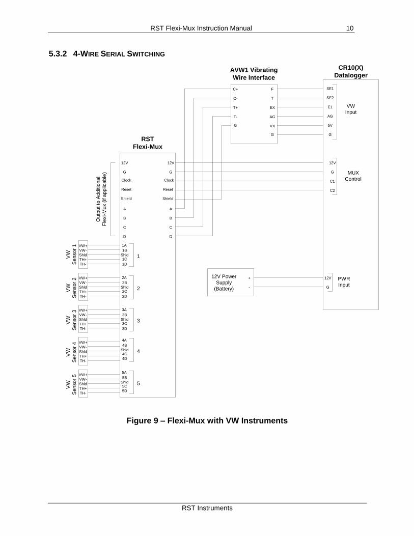
5.3.2 4-WIRE SERIAL SWITCHING
SE1
SE2
E1
AG
5V
G
VW
Input
12V
G
C1
C2
MUX
Control
12V
G
Clock
Reset
Shield
A
B
C
D
F
T
EX
AG
VX
G
C+
C-
T+
T-
G
CR10(X)
DataloggerAVW1 Vibrating
Wire Interface
12V
G
Clock
Reset
Shield
A
B
C
D
Outp
ut
to A
dditio
nal
Fle
xi-M
ux (
if a
pplic
able
)
VW+
VW-
Shld
TH+
TH-
VW+
VW-
Shld
TH+
TH-
VW+
VW-
Shld
TH+
TH-
VW+
VW-
Shld
TH+
TH-
VW
Sensor
1
VW
Sensor
2
VW
Sensor
3
VW
Sensor
4
1A
1B
1C
1D
Shld 1
2A
2B
2C
2D
Shld 2
3A
3B
3C
3D
Shld 3
4A
4B
4C
4D
Shld 4
RST
Flexi-Mux
12V Power
Supply
(Battery)
+
-
12V
G
PWR
Input
VW+
VW-
Shld
TH+
TH-
VW
Sensor
5
5A
5B
5C
5D
Shld 5
Figure 9 – Flexi-Mux with VW Instruments
RST Flexi-Mux Instruction Manual
RST Instruments
11
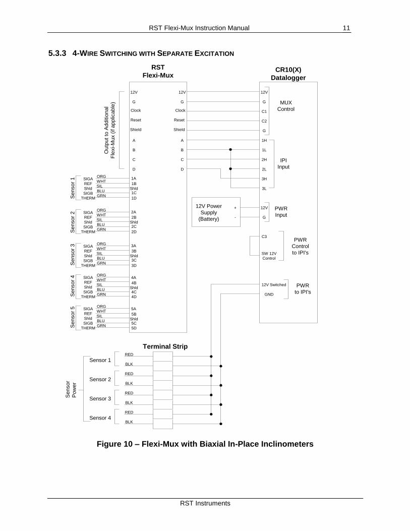
5.3.3 4-WIRE SWITCHING WITH SEPARATE EXCITATION
12V
G
C1
C2
MUX
Control
12V
G
Clock
Reset
Shield
A
B
C
D
CR10(X)
Datalogger
12V
G
Clock
Reset
Shield
A
B
C
D
Outp
ut
to A
dditio
nal
Fle
xi-M
ux (
if a
pplic
able
)
SIGA
REF
Shld
SIGB
THERMSensor
1 S
ensor
2 S
ensor
3 S
ensor
4
1A
1B
1C
1D
Shld
2A
2B
2C
2D
Shld
3A
3B
3C
3D
Shld
4A
4B
4C
4D
Shld
RST
Flexi-Mux
12V Power
Supply
(Battery)
+
-
12V
G
PWR
Input
G
1H
1L
2H
2L
3H
3L
IPI
Input
C3
SW 12V
Control
PWR
Control
to IPI's
Terminal StripRED
BLKSensor 1
RED
BLKSensor 2
RED
BLKSensor 3
RED
BLKSensor 4
12V Switched
GND
PWR
to IPI's
ORG
WHT
SIL
BLU
GRN
SIGA
REF
Shld
SIGB
THERM
ORG
WHT
SIL
BLU
GRN
SIGA
REF
Shld
SIGB
THERM
ORG
WHT
SIL
BLU
GRN
SIGA
REF
Shld
SIGB
THERM
ORG
WHT
SIL
BLU
GRN
Sensor
Pow
er
Sensor
5 5A
5B
5C
5D
Shld
SIGA
REF
Shld
SIGB
THERM
ORG
WHT
SIL
BLU
GRN
Figure 10 – Flexi-Mux with Biaxial In-Place Inclinometers

RST Flexi-Mux Instruction Manual
RST Instruments
12
5.3.4 8-WIRE SERIES/PARALLEL SWITCHING
12V
G
C1
C2
MUX
Control
12V
G
Clock
Reset
Shield
A
B
C
D
CR10(X)
Datalogger
12V
G
Clock
Reset
Shield
A
B
C
DO
utp
ut
to A
dditio
nal
Fle
xi-M
ux (
if a
pplic
able
)1A
1B
1C
1D
Shld
RST
Flexi-Mux 1
12V Power
Supply
(Battery)
+
-
12V
G
PWR
Input
G
Analog
Input
12V
G
Clock
Reset
Shield
A
B
C
D
12V
G
Clock
Reset
Shield
A
B
C
D
Outp
ut
to A
dditio
nal
Fle
xi-M
ux (
if a
pplic
able
)
1A
1B
1C
1D
Shld
RST
Flexi-Mux 2
SE1
SE2
SE3
SE4
SE5
SE6
E1
AG
Analog
Input
Exte
nsom
ete
r #1
C1
C2
C3C4
Shld
Exte
nsom
ete
r #1
C5
C6
Shld
PS+
PS-
P+
P-
E2
AG
Excitation
Output Voltage
OU
T
IN
OU
T
IN
Figure 11 – Flexi-Mux wired in Parallel to Switch 8-wires
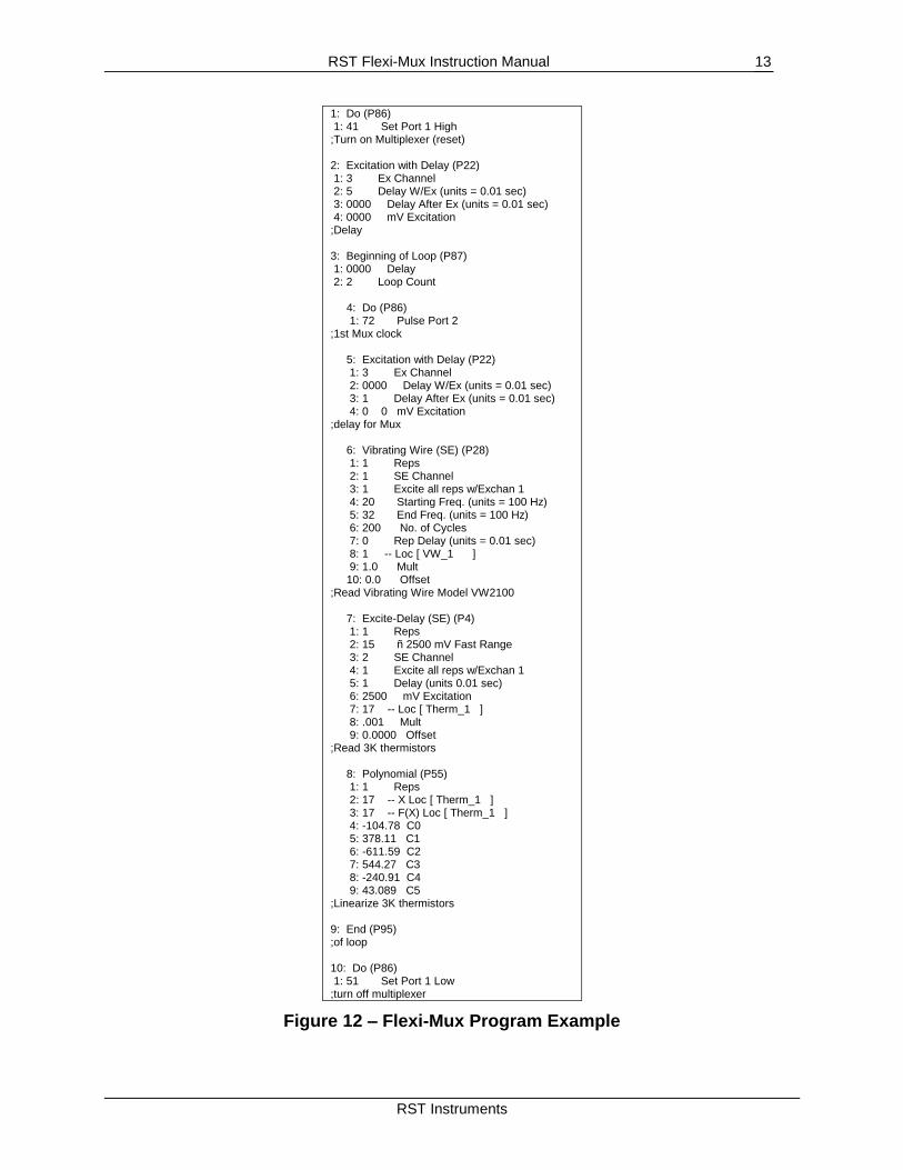
5.4 DATALOGGER PROGRAMMING The following table outlines the basic program instructions which can be used to activate the RST Flexi-Mux and measure RST Vibrating Wire Piezometers with Campbell Scientific Dataloggers. Please note that this is a very basic example only, there are many options available.
RST Flexi-Mux Instruction Manual
RST Instruments
13
1: Do (P86) 1: 41 Set Port 1 High ;Turn on Multiplexer (reset) 2: Excitation with Delay (P22) 1: 3 Ex Channel 2: 5 Delay W/Ex (units = 0.01 sec) 3: 0000 Delay After Ex (units = 0.01 sec) 4: 0000 mV Excitation ;Delay 3: Beginning of Loop (P87) 1: 0000 Delay 2: 2 Loop Count 4: Do (P86) 1: 72 Pulse Port 2 ;1st Mux clock 5: Excitation with Delay (P22) 1: 3 Ex Channel 2: 0000 Delay W/Ex (units = 0.01 sec) 3: 1 Delay After Ex (units = 0.01 sec) 4: 0 0 mV Excitation ;delay for Mux 6: Vibrating Wire (SE) (P28) 1: 1 Reps 2: 1 SE Channel 3: 1 Excite all reps w/Exchan 1 4: 20 Starting Freq. (units = 100 Hz) 5: 32 End Freq. (units = 100 Hz) 6: 200 No. of Cycles 7: 0 Rep Delay (units = 0.01 sec) 8: 1 -- Loc [ VW_1 ] 9: 1.0 Mult 10: 0.0 Offset ;Read Vibrating Wire Model VW2100 7: Excite-Delay (SE) (P4) 1: 1 Reps 2: 15 ñ 2500 mV Fast Range 3: 2 SE Channel 4: 1 Excite all reps w/Exchan 1 5: 1 Delay (units 0.01 sec) 6: 2500 mV Excitation 7: 17 -- Loc [ Therm_1 ] 8: .001 Mult 9: 0.0000 Offset ;Read 3K thermistors 8: Polynomial (P55) 1: 1 Reps 2: 17 -- X Loc [ Therm_1 ] 3: 17 -- F(X) Loc [ Therm_1 ] 4: -104.78 C0 5: 378.11 C1 6: -611.59 C2 7: 544.27 C3 8: -240.91 C4 9: 43.089 C5 ;Linearize 3K thermistors 9: End (P95) ;of loop 10: Do (P86) 1: 51 Set Port 1 Low ;turn off multiplexer
Figure 12 – Flexi-Mux Program Example
RST Flexi-Mux Instruction Manual
RST Instruments
14
The above program example assumes that the Flexi-Mux DIP switches are set to 4-wire switching, therefore a pulse for the reset and clock lines will switch 4 wires (VW sensor and thermistor).
6 SPECIFICATIONS
Power 12 Vdc (under load), unregulated
Current Drain 10µA quiescent; 8mA active
Reset Active Levels, max. 2.0V
Clock Active Levels, max. 2.0V
Min. Clock Pulse Width 1 ms
Max. Actuation Relay Time 20 ms
Relay Operation Break before make
Initial Relay Resistance, closed 0.1 Ohm
Max. Switching Current 1A
Min. Contact Life 107 closures
Operating Temp. -40oC to 70
oC (-40
oF to 158
oF) - extended
Size 20.7cm(8.15”H) x 8.5cm (3.17”W) x 2.7cm (1.05”D)
Weight 0.24kg (0.53lbs.)