rtcu dx4i pro mk2 - logic io dx4i pro mk2 technical manual 2.01.pdf · rtcu dx4i pro mk2 technical...
TRANSCRIPT
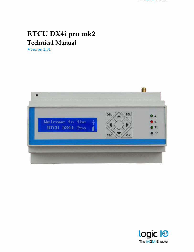
RTCU DX4i pro mk2 Technical Manual Version 2.01
RTCU DX4i pro mk2 Technical Manual V2.01
Logic IO ApS. Ph: (+45) 7625 0210
Holmboes Allé 14 Fax: (+45) 7625 0211
8700 Horsens Page 2 of 40 Email: [email protected]
Denmark www.logicio.com
Introduction
This manual contains technical documentation which allows for easy installation and use of the
RTCU DX4i pro mk2 product line. For information on the programming and software
configuration of the product please refer to the RTCU IDE documentation.
The RTCU DX4i pro mk2 includes the RTCU DX4i pro-2G and the RTCU DX4i pro-3G that are
both a minor upgrade to the former RTCU DX4i pro adding an UMTS/HSPA variant.
The RTCU DX4i pro mk2 has been designed from the ground up for professional wireless
industrial applications with its strong on-board I/O capabilities and multiple communication
interfaces such as: dual RS232, dual RS485, 1-Wire, CAN and USB.
Housed in a standard DIN-rail encapsulation, it is a perfect component for automation and control
applications.
The on-board I/O system can be expanded almost indefinitely and completely transparently by
adding external MODBUS compatible I/O modules! This unique I/O expansion capability,
combined with the ability to operate as a MODBUS master and slave simultaneously, positions the
RTCU DX4i pro as the perfect product for SCADA-like applications.
The RTCU DX4i pro mk2 is based on the X32 Execution Architecture offering high performance
along with a large memory capacity for both program and data - meeting the requirements of
today’s most demanding and sophisticated M2M/IoT applications.
The RTCU DX4i pro mk2 rests on the RTCU M2M Platform which brings all the necessary tools
together to develop, implement and maintain today’s sophisticated M2M/IoT applications.
The development task is supported by the free RTCU IDE development environment,
complimented by a large and comprehensive documentation and application example library.
The RTCU Gateway 2 is the corner stone of the communication infrastructure and ensures reliable
two-way device communication in any network environment.
Deploying and maintaining new application and firmware versions for devices in the field is
handled by the powerful RTCU Deployment Server.
For detailed information on the powerful RTCU M2M Platform, please refer to the
RTCU M2M Platform datasheet.
Any reference to the RTCU DX4i pro in this document implicitly refers to both the RTCU DX4i pro-2G
and the RTCU DX4i pro-3G unless otherwise stated.
RTCU DX4i pro mk2 Technical Manual V2.01
Logic IO ApS. Ph: (+45) 7625 0210
Holmboes Allé 14 Fax: (+45) 7625 0211
8700 Horsens Page 3 of 40 Email: [email protected]
Denmark www.logicio.com
The technical highlights of the RTCU DX4i pro mk2:
Based on the RTCU M2M Platform1.
X32 execution architecture.
o RTCU IDE development tool with full a featured device emulator.
o Huge standard API with more than 800+ functions.
o Comprehensive protocol support, including:
TCP-UDP/IP, FTP, SMTP, RACP, MQTT, MODBUS.
World-wide Penta-band UMTS/HSPA UMTS engine, or
World-wide Quad-band GSM engine.
Digitized audio can be played over GSM or to an external device (DX4i pro-2G).
DTMF support for Interactive Voice Response applications (DX4i pro-2G).
Graphical 144x32 pixels display with white-on-blue back-lit text/graphics.
Keypad with 8 keys for sophisticated user interaction and control.
Large data-flash/logger memory with a capacity of 4.5 MB.
Internal 4 MB FAT32 flash drive.
Standard FAT32 SD-CARD reader with up to 32 GB capacity.
2 x RS232 channels and 2 x RS485 channels.
4 x analog inputs with 0..10 volt / 0..20 mA with 12 bit precision.
4 x analog outputs with 0..10 volt / 0..20 mA.
8 x digital inputs and 8 x high-power solid-state digital outputs.
Up to 4 digital inputs can be configured as IEC62053-31 Class A compliant.
Expandable I/O with standard MODBUS modules.
Full CAN 2.0B controller with hardware filtering and multi-speed support.
1-Wire bus for accessories such as ID-button reader, temperature sensors, etc.
Wide operating range from 8..36 VDC.
On-board high-capacity Li-Ion battery.
Advanced power-management with wake-up on a wide range of events.
High-speed Mini-USB programming connector.
Housed in an industry standard M36 DIN compliant encapsulation.
Two-part pluggable connectors for easy installation and maintenance.
Fully supported by the RTCU Gateway 2 and the RTCU Deployment Server.
Accessories: MODBUS modules, Wi-Fi, Ethernet, Bluetooth and 2 MP camera.
1 Please see “The RTCU M2M Platform” data sheet for more information.
RTCU DX4i pro mk2 Technical Manual V2.01
Logic IO ApS. Ph: (+45) 7625 0210
Holmboes Allé 14 Fax: (+45) 7625 0211
8700 Horsens Page 4 of 40 Email: [email protected]
Denmark www.logicio.com
* * * * THIS PAGE IS INTENTIONALLY LEFT BLANK * * *
RTCU DX4i pro mk2 Technical Manual V2.01
Logic IO ApS. Ph: (+45) 7625 0210
Holmboes Allé 14 Fax: (+45) 7625 0211
8700 Horsens Page 5 of 40 Email: [email protected]
Denmark www.logicio.com
Table of contents
Introduction......................................................................................................................................................2
The technical highlights of the RTCU DX4i pro mk2: ................................................................................3
Graphical view.................................................................................................................................................6
External connections .......................................................................................................................................7
Overview ......................................................................................................................................................7
Signal Overview ..........................................................................................................................................9
Power supply .............................................................................................................................................12
Digital outputs...........................................................................................................................................13
Digital inputs / S0 inputs / Ignition input..............................................................................................14
S0 compliant inputs (IEC62053-31, Class A compatible)..................................................................14
Wakeup (ignition) input .......................................................................................................................15
Analog inputs ............................................................................................................................................16
Analog outputs ..........................................................................................................................................17
RS232 port 1 ...............................................................................................................................................18
RS232 port 2 ...............................................................................................................................................18
RS485 communication ports (EIA/TIA-485-A compatible) .................................................................19
RS485 port 1 ...........................................................................................................................................19
RS485 port 2 ...........................................................................................................................................19
CAN communication port .......................................................................................................................20
1-Wire bus ..................................................................................................................................................21
DC-Out........................................................................................................................................................21
User interface .................................................................................................................................................22
Graphical LCD display.............................................................................................................................22
Keypad........................................................................................................................................................23
LED Indicators ...............................................................................................................................................24
User LED A and B .....................................................................................................................................24
System LED S1 and S2 ..............................................................................................................................25
Switches ..........................................................................................................................................................26
DIP-switch..................................................................................................................................................26
System switch (RST)..................................................................................................................................26
Internal Li-Ion battery...................................................................................................................................27
GSM / UMTS ..................................................................................................................................................28
SIM-Card.........................................................................................................................................................28
GSM / UMTS Antenna ..................................................................................................................................28
SD-CARD reader ...........................................................................................................................................29
Approved SD-CARDs...............................................................................................................................29
Barcode............................................................................................................................................................30
Power consumption ......................................................................................................................................31
Appendix A – Unit configuration guide ....................................................................................................32
Opening the lid..........................................................................................................................................35
Closing the lid:...........................................................................................................................................37
Appendix B – Installing the SIM-Card .......................................................................................................38
Appendix C – Installing the SD-CARD ......................................................................................................39
RTCU DX4i pro mk2 Specifications ............................................................................................................40

RTCU DX4i pro mk2 Technical Manual V2.01
Logic IO ApS. Ph: (+45) 7625 0210
Holmboes Allé 14 Fax: (+45) 7625 0211
8700 Horsens Page 6 of 40 Email: [email protected]
Denmark www.logicio.com
Graphical view
RTCU DX4i pro mk2 Technical Manual V2.01
Logic IO ApS. Ph: (+45) 7625 0210
Holmboes Allé 14 Fax: (+45) 7625 0211
8700 Horsens Page 7 of 40 Email: [email protected]
Denmark www.logicio.com
External connections
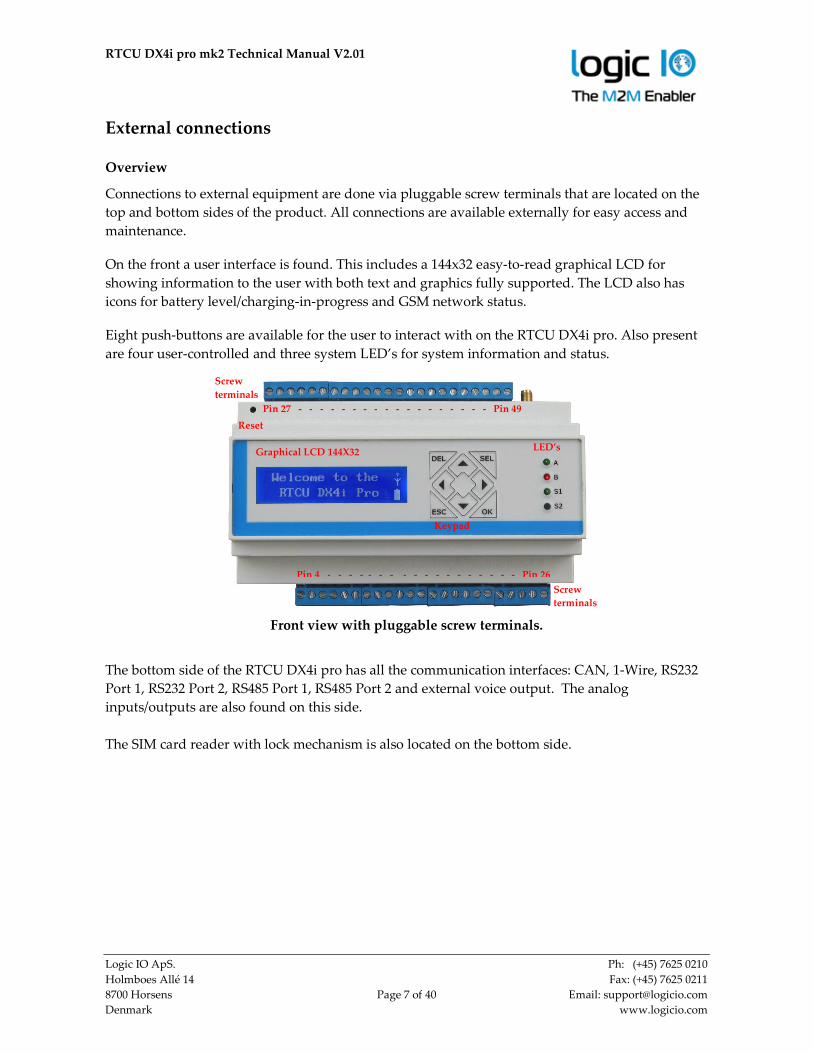
Overview
Connections to external equipment are done via pluggable screw terminals that are located on the
top and bottom sides of the product. All connections are available externally for easy access and
maintenance.
On the front a user interface is found. This includes a 144x32 easy-to-read graphical LCD for
showing information to the user with both text and graphics fully supported. The LCD also has
icons for battery level/charging-in-progress and GSM network status.
Eight push-buttons are available for the user to interact with on the RTCU DX4i pro. Also present
are four user-controlled and three system LED’s for system information and status.
Front view with pluggable screw terminals.
The bottom side of the RTCU DX4i pro has all the communication interfaces: CAN, 1-Wire, RS232
Port 1, RS232 Port 2, RS485 Port 1, RS485 Port 2 and external voice output. The analog
inputs/outputs are also found on this side.
The SIM card reader with lock mechanism is also located on the bottom side.
Graphical LCD 144X32
Screw
terminals
Pin 27 - - - - - - - - - - - - - - - - - - Pin 49
Reset
Keypad
LED’s
Pin 4 - - - - - - - - - - - - - - - - - - Pin 26
Screw
terminals

RTCU DX4i pro mk2 Technical Manual V2.01
Logic IO ApS. Ph: (+45) 7625 0210
Holmboes Allé 14 Fax: (+45) 7625 0211
8700 Horsens Page 8 of 40 Email: [email protected]
Denmark www.logicio.com
Bottom-side view
On the top side of the RTCU DX4i pro, the following interfaces are found: power, digital inputs,
digital outputs and an SMA female connector for an external GSM antenna.
The SD-CARD reader and three DIP switches are also found on this side. Finally the mini USB-B
connector used as programming/service interface is located on the top side.
Top-side view
The RTCU DX4i pro uses two-way pluggable screw terminals for maximum flexibility and easy
installation and maintenance.
X1: SER1
SIM CARD
X2: SER2
Pin 4 - - - - - - - - - - - - - - - - - - - - Pin 26
1 4
3 6
Pin 49 - - - - - - - - - - - - - - - Pin 27
GSM Antenna
SD-CARD X3: Mini USB-B
DIP1-4
RTCU DX4i pro mk2 Technical Manual V2.01
Logic IO ApS. Ph: (+45) 7625 0210
Holmboes Allé 14 Fax: (+45) 7625 0211
8700 Horsens Page 9 of 40 Email: [email protected]
Denmark www.logicio.com
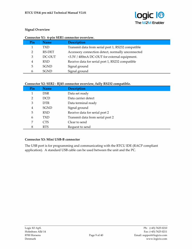
Signal Overview
Connector X1: 6-pin SER1 connector overview.
Pin Name Description
1 TXD Transmit data from serial port 1, RS232 compatible
2 RS-DET Accessory connection detect, normally unconnected
3 DC-OUT +3.3V / 400mA DC-OUT for external equipment.
4 RXD Receive data for serial port 1, RS232 compatible
5 SGND Signal ground
6 SGND Signal ground
Connector X2: SER2 - RJ45 connector overview, fully RS232 compatible.
Pin Name Description
1 DSR Data set ready
2 DCD Data carrier detect
3 DTR Data terminal ready
4 SGND Signal ground
5 RXD Receive data for serial port 2
6 TXD Transmit data from serial port 2
7 CTS Clear to send
8 RTS Request to send
Connector X3: Mini USB-B connector
The USB port is for programming and communicating with the RTCU IDE (RACP compliant
application). A standard USB cable can be used between the unit and the PC.

RTCU DX4i pro mk2 Technical Manual V2.01
Logic IO ApS. Ph: (+45) 7625 0210
Holmboes Allé 14 Fax: (+45) 7625 0211
8700 Horsens Page 10 of 40 Email: [email protected]
Denmark www.logicio.com
Pin 4 - 26 overview
Pin Name Description
4 CAN-H CAN-bus H-signal
5 CAN-L CAN-bus L-signal
6 SGND Signal ground
7 1Wire 1-Wire bus for accessories such as ID-Button / temperature sensors
8 1Wire-LED 1-Wire ID-Button LED
9 SGND Signal ground
10 RS485_1+ RS485 non-inverting signal for RS485 port 1
11 RS485_1- RS485 inverting signal for RS485 port 1
12 SGND Signal ground
13 RS485_2+ RS485 non-inverting signal for RS485 port 2
14 RS485_2- RS485 inverting signal for RS485 port 2
15 SGND Signal ground
16 Voice External voice
17 AIN1 Analog input 1
18 AIN2 Analog input 2
19 AIN3 Analog input 3
20 AIN4 Analog input 4
21 AGND Analog ground
22 AOUT1 Analog output 1
23 AOUT2 Analog output 2
24 AOUT3 Analog output 3
25 AOUT4 Analog output 4
26 AGND Analog ground

RTCU DX4i pro mk2 Technical Manual V2.01
Logic IO ApS. Ph: (+45) 7625 0210
Holmboes Allé 14 Fax: (+45) 7625 0211
8700 Horsens Page 11 of 40 Email: [email protected]
Denmark www.logicio.com
Pin 27 - 49 overview
Pin Name Description
27 PGND Power ground, negative (-) connection
28 SUPP Power supply, positive (+) connection
29 SUPP Power supply, positive (+) connection
30 DOUT1 Digital output 1
31 DOUT2 Digital output 2
32 DOUT3 Digital output 3
33 DOUT4 Digital output 4
34 DOUT5 Digital output 5
35 DOUT6 Digital output 6
36 DOUT7 Digital output 7
37 DOUT8 Digital output 8
38 SGND Signal ground
39 SGND Signal ground
40 DIN1 / S0IN1 Digital input 1 / S0 input 1
41 DIN2 / S0IN2 Digital input 2 / S0 input 2
42 DIN3 / S0IN3 Digital input 3 / S0 input 3
43 DIN4 / S0IN4 Digital input 4 / S0 input 4
44 DIN5 / WAKEUP Digital input 5 / Wakeup (ignition) input
45 DIN6 Digital input 6
46 DIN7 Digital input 7
47 DIN8 Digital input 8
48 SGND Signal ground
49 SGND Signal ground
Accessories available for cable assembly
Order-code Name
RT-O-TYCO-H6
TYCO p/n: 794617-6
Tyco, Connector house 6 pins. Bag with 10 pcs
RT-O-TYCO-CR
TYCO p/n: 794606-1
Tyco, Crimp Contacts for connector house. Wire size 0.2 to 0.5 mm2. Bag
with 100 pcs.
RT-O-TYCO-TOOL
TYCO p/n: 91501-1
Tyco, Crimp hand tool for easy assembly of TYCO crimp contacts.
Wire size 0.2 to 0.5 mm2
Recommended tool:
Alternative tools:
Tyco 91501-1 (0.20 to 0.50mm2) RS 495-9675, Farnell 1111475
Tyco 91502-1 (0.05 to 0.15mm2) RS 495-9675, Farnell 1111476
Molex 69008-0982 (0.20 to 0.50mm2) RS 233-3059, Farnell 673122
Molex 69008-0983 (0.05 to 0.05mm2) RS 233-3065, Farnell 673134
Extraction tool: Tyco 843996-6 extraction tool. RS 495-9704, Farnell 1111477

RTCU DX4i pro mk2 Technical Manual V2.01
Logic IO ApS. Ph: (+45) 7625 0210
Holmboes Allé 14 Fax: (+45) 7625 0211
8700 Horsens Page 12 of 40 Email: [email protected]
Denmark www.logicio.com
Power supply
The RTCU DX4i pro unit can be supplied with 8..36VDC from an external DC power source.
Positive power is applied to the SUPP pin and ground is connected to the PGND pin. There are
two SUPP pins, as these also supply the digital outputs. If the total current consumption of the
digital outputs exceeds 1A, please refer to the digital output section for more information on the
wiring. Otherwise one pin is sufficient.
There are three different ground labels: Power Ground (PGND), Signal Ground (SGND) and
Analog Ground (AGND). The signal and analog grounds are filtered from the power ground.
Power ground must only be used as a power supply return path. The signal ground is used as
ground reference for digital I/O’s and serial interfaces. The analog ground is used as a low noise
analog ground reference for the analog inputs.
The RTCU DX4i pro is protected against wrong polarity. If a chassis or system ground is connected
to either SGND or AGND, a wrong polarity on the supply lines will destroy the internal GND
connection.
The RTCU DX4i pro also contains an internal high capacity backup battery which will supply the
RTCU if the external power supply fails or is disconnected. By default the RTCU is powered down
when a power fail occurs. This setting, however, can be changed. Please consult the RTCU IDE on-
line help for more information. The display will automatically turn off when external power is
removed.
When the wakeup/ignition input is activated with a logical high, the RTCU DX4i pro unit will
wake-up if it was in power-down mode.
Please Note:
• Minimum 12VDC supply is necessary for 0-10V analog output configuration.
• Minimum 16VDC supply is necessary for digital inputs 1-4 to work as S0 compliant inputs.
Power supply pins
Pin Name Description
27 PGND Power ground, negative (-) connection
28 SUPP Power supply, positive (+) connection
29 SUPP Power supply, positive (+) connection
RTCU DX4i pro mk2 Technical Manual V2.01
Logic IO ApS. Ph: (+45) 7625 0210
Holmboes Allé 14 Fax: (+45) 7625 0211
8700 Horsens Page 13 of 40 Email: [email protected]
Denmark www.logicio.com
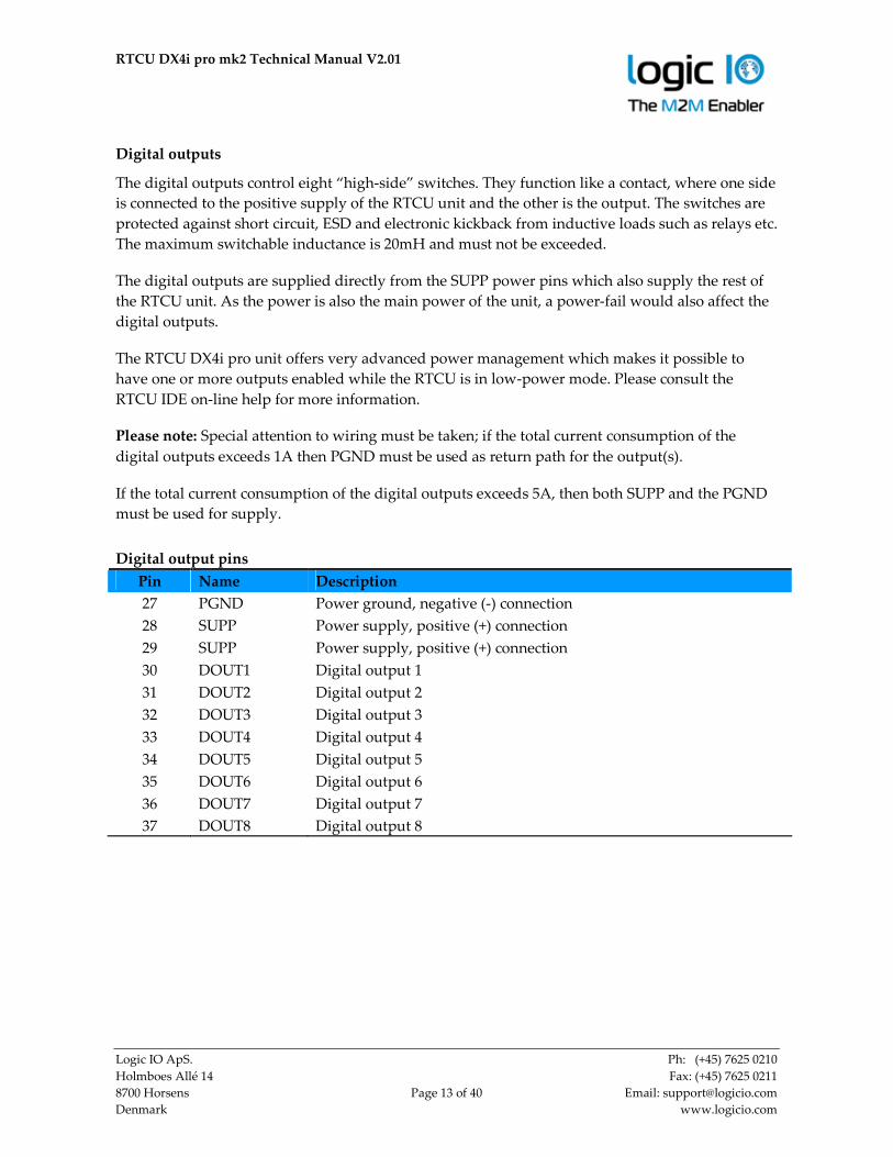
Digital outputs
The digital outputs control eight “high-side” switches. They function like a contact, where one side
is connected to the positive supply of the RTCU unit and the other is the output. The switches are
protected against short circuit, ESD and electronic kickback from inductive loads such as relays etc.
The maximum switchable inductance is 20mH and must not be exceeded.
The digital outputs are supplied directly from the SUPP power pins which also supply the rest of
the RTCU unit. As the power is also the main power of the unit, a power-fail would also affect the
digital outputs.
The RTCU DX4i pro unit offers very advanced power management which makes it possible to
have one or more outputs enabled while the RTCU is in low-power mode. Please consult the
RTCU IDE on-line help for more information.
Please note: Special attention to wiring must be taken; if the total current consumption of the
digital outputs exceeds 1A then PGND must be used as return path for the output(s).
If the total current consumption of the digital outputs exceeds 5A, then both SUPP and the PGND
must be used for supply.
Digital output pins
Pin Name Description
27 PGND Power ground, negative (-) connection
28 SUPP Power supply, positive (+) connection
29 SUPP Power supply, positive (+) connection
30 DOUT1 Digital output 1
31 DOUT2 Digital output 2
32 DOUT3 Digital output 3
33 DOUT4 Digital output 4
34 DOUT5 Digital output 5
35 DOUT6 Digital output 6
36 DOUT7 Digital output 7
37 DOUT8 Digital output 8
RTCU DX4i pro mk2 Technical Manual V2.01
Logic IO ApS. Ph: (+45) 7625 0210
Holmboes Allé 14 Fax: (+45) 7625 0211
8700 Horsens Page 14 of 40 Email: [email protected]
Denmark www.logicio.com
Digital inputs / S0 inputs / Ignition input
The eight digital inputs are all low-pass filtered (450kHz) and transient-protected. To activate the
inputs, connect a positive voltage between the corresponding input (DINx) and SGND.
Digital input 1-4 can be configured individually as S0 input (IEC62053-31, Class A) and DIN5 can
work as a wakeup (ignition) input.
As default the digital inputs are configured as normal inputs. For placement and configuration of
the hardware jumpers inside the unit, please refer to the configuration guide in Appendix A.
S0 compliant inputs (IEC62053-31, Class A compatible)
In S0 configuration the relevant RTCU DX4i pro input will act as a ‘pulse input device’, and a
current is supplied into the input connector so that a simple switch between SGND and the
appropriate input will activate it. This is used in most electricity metering equipment.
Please note: The RTCU DX4i pro unit must be supplied with a minimum of 16 VDC for the S0
mode to work correctly.
S0 must also be enabled from the application in order to work as an S0 compliant input.

RTCU DX4i pro mk2 Technical Manual V2.01
Logic IO ApS. Ph: (+45) 7625 0210
Holmboes Allé 14 Fax: (+45) 7625 0211
8700 Horsens Page 15 of 40 Email: [email protected]
Denmark www.logicio.com
Wakeup (ignition) input
The DIN5 / wakeup (ignition) input is a special input in that it also functions as the wakeup input.
If the input is activated with a logical high or low (Wait For Event mode only) when the RTCU
DX4i pro is in low-power mode it will wake-up the unit. A power apply will also wake the unit up
if it is in power-down mode or in Wait For Event mode with power Apply and/or ignition selected
for wakeup. The input is de-bounced with a period between 1-2 ms when used as a digital input.
So any logical level applied to this input must be greater than 2 ms to be valid.
The power management allows for the possibility of configuring a wakeup on one or more digital
inputs with individually configured falling- or rising edge detection. Please consult the RTCU IDE
on-line help for more information.
Digital input pins
Pin Name Description Jumper Setting
40 DIN1 / S0IN1 S0 input 1
Digital input 1
JP8 position 1-2
JP8 position 2-3 (default)
41 DIN2 / S0IN2 S0 input 2
Digital input 2
JP9 position 1-2
JP9 position 2-3 (default)
42 DIN3 / S0IN3 S0 input 3
Digital input 3
JP10 position 1-2
JP10 position 2-3 (default)
43 DIN4 / S0IN4 S0 input 4
Digital input 4
JP11 position 1-2
JP11 position 2-3 (default)
44 DIN5 / WAKEUP Digital input 5
Wakeup (ignition) input
45 DIN6 Digital input 6
46 DIN7 Digital input 7
47 DIN8 Digital input 8
48 SGND Signal ground
49 SGND Signal ground
For placement and configuration of the hardware jumpers inside the unit, please refer to the unit
configuration guide in Appendix A.

RTCU DX4i pro mk2 Technical Manual V2.01
Logic IO ApS. Ph: (+45) 7625 0210
Holmboes Allé 14 Fax: (+45) 7625 0211
8700 Horsens Page 16 of 40 Email: [email protected]
Denmark www.logicio.com
Analog inputs
The RTCU DX4i pro unit has four analog inputs which can be configured individually to work
either as voltage or current measurement inputs by using the configuration jumper. The range in
voltage mode is 0-10VDC and in current mode it is 0-20mA.
The conversion resolution is 12 bit.
By default the analog inputs are configured as voltage inputs, and are converted to a digital value
with a resolution of 10-bit before being presented to the application (0..1023). The application can
change the resolution to the full 12 bit (0..4095). Please consult the RTCU IDE for further details.
The input signal is connected between AINx and AGND. AGND must be connected to the
reference of the connected equipment. Please be aware that deviations may occur, as the system is
very noise sensitive. Avoid long, unshielded wires and high current, fast changing signals routed
parallel to the analog signals.
Analog input pins
Pin Name Description Jumper Setting
17 AIN1 Analog input 1 – Voltage
Analog input 1 – Current
JP1 not installed (default)
JP1 installed
18 AIN2 Analog input 2 – Voltage
Analog input 2 – Current
JP14 not installed (default)
JP14 installed
19 AIN3 Analog input 3 – Voltage
Analog input 3 – Current
JP16 not installed (default)
JP16 installed
20 AIN4 Analog input 4 – Voltage
Analog input 4 – Current
JP17 not installed (default)
JP17 installed
21 AGND Analog ground
26 AGND Analog ground
Specification for each analog input (voltage mode)
Min. Typ. Max. Unit
0 - 10 VDC
Resolution - - 12 Bit
Precision -1.5 - 1.5 %FSR
Cut-off frequency - 4.5 - kHz
Input impedance - 40 - kΩ
Protected against transients and
low-pass filtered
Precision is based on
measurements @ 25 ˚C
Specification for each analog input (current mode)
Min. Typ. Max. Unit
0 - 20 mA
Resolution - - 12 Bit
Precision -1.5 - 1.5 %FSR
Cut-off frequency - 4.5 - kHz
Input impedance - 504 - Ω
Protected against transients and
low-pass filtered
Precision is based on
measurements @ 25 ˚C

RTCU DX4i pro mk2 Technical Manual V2.01
Logic IO ApS. Ph: (+45) 7625 0210
Holmboes Allé 14 Fax: (+45) 7625 0211
8700 Horsens Page 17 of 40 Email: [email protected]
Denmark www.logicio.com
Analog outputs
The analog outputs can individually be configured to work either as voltage or current outputs.
The range in voltage mode is 0-10VDC and in current mode it is 0-20mA. The resolution of the
digital-to-analog converter is 10bit or 1024 in decimal scale.
The decimal value for 10V/20mA output are 1023 and 512 for 5V/10mA.
As default the outputs are configured as voltage outputs. For placement and configuration of the
hardware jumpers inside the unit, please refer to the unit configuration guide in Appendix A.
The output signal is connected to external equipment between AOUTx and AGND. AGND must
be connected to the reference of the connected equipment. Please be aware that deviations may
occur, as the system is very noise sensitive. Avoid long unshielded wires and large fast-changing
signals routed parallel to the analog signals. In current mode the specifications for the analog
output only valid if the load is maximal 250Ω.
Each output is ESD and transient protected.
Please note: The RTCU DX4i pro unit must be supplied with minimum 12VDC in order for the
analog outputs to work according to specifications.
Analog output pins
Pin Name Description Jumper Setting
22 AOUT1 Analog output 1 – Voltage
Analog output 1 – Current
JP2 position 2-3 (default)
JP2 position 1-2
23 AOUT2 Analog output 2 – Voltage
Analog output 2 – Current
JP3 position 2-3 (default)
JP3 position 1-2
24 AOUT3 Analog output 3 – Voltage
Analog output 3 – Current
JP4 position 2-3 (default)
JP4 position 1-2
25 AOUT4 Analog output 4 – Voltage
Analog output 4 – Current
JP6 position 2-3 (default)
JP6 position 1-2
21 AGND Analog ground
26 AGND Analog ground
RTCU DX4i pro mk2 Technical Manual V2.01
Logic IO ApS. Ph: (+45) 7625 0210
Holmboes Allé 14 Fax: (+45) 7625 0211
8700 Horsens Page 18 of 40 Email: [email protected]
Denmark www.logicio.com
RS232 port 1
This port can be used as a general-purpose RS232 serial port and does not support handshaking.
This port can also be used for communication with the RTCU accessories. This serial port shares its
resources with the RS485 port 2 and only one of them can be active at a given time.
X1: SER1 connector overview (6-pin TYCO Mate-n-Lock)
Pin Name Description
1 TXD Transmit data from serial port 1, RS232 compatible
4 RXD Receive data for serial port 1, RS232 compatible
2 RS-DET RTCU accessories detection
5 SGND Signal ground
6 SGND Signal ground
RS232 port 2
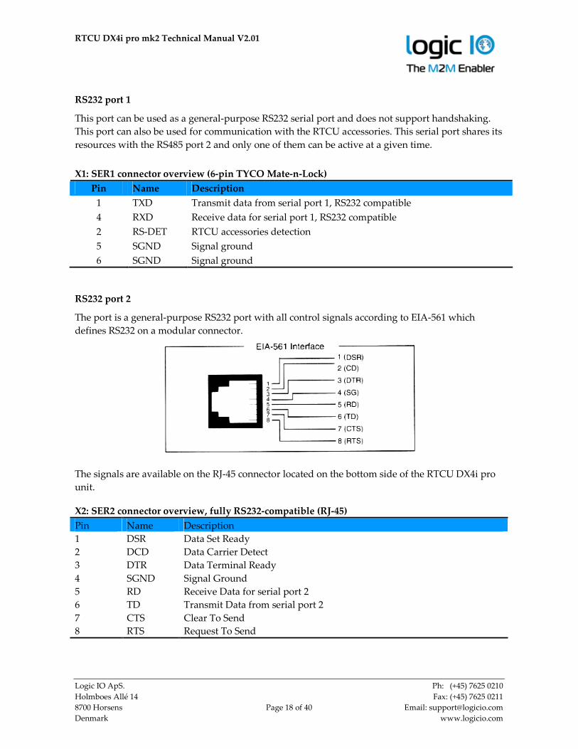
The port is a general-purpose RS232 port with all control signals according to EIA-561 which
defines RS232 on a modular connector.
The signals are available on the RJ-45 connector located on the bottom side of the RTCU DX4i pro
unit.
X2: SER2 connector overview, fully RS232-compatible (RJ-45)
Pin Name Description
1 DSR Data Set Ready
2 DCD Data Carrier Detect
3 DTR Data Terminal Ready
4 SGND Signal Ground
5 RD Receive Data for serial port 2
6 TD Transmit Data from serial port 2
7 CTS Clear To Send
8 RTS Request To Send

RTCU DX4i pro mk2 Technical Manual V2.01
Logic IO ApS. Ph: (+45) 7625 0210
Holmboes Allé 14 Fax: (+45) 7625 0211
8700 Horsens Page 19 of 40 Email: [email protected]
Denmark www.logicio.com
RS485 communication ports (EIA/TIA-485-A compatible)
RS485 is a multi-drop network with a maximum of 32 units connected simultaneously to the bus.
The RS485 bus contains an RS485+ (non-inverting) and an RS485- (inverting) signal as well as a
signal ground which must always be connected to the common signal ground for all units
connected to the RS485 bus!
The maximum cable length for the RS485 bus is according to the EIA/TIA-485-A standard (max.
1200m @ <100kbit); this limit is highly influenced by the quality of the cable, signaling rate, noise
etc.
At longer cable lengths, noisy environments, or high communication speeds, it might be necessary
to terminate the transmission line with a 1201 ohm resistor at each end of the transmission line to
terminate it and avoid signal reflections. If the RTCU DX4i pro is used as an endpoint unit, the
hardware jumper JP7 (port 1) / JP12 (port 2) can be installed to terminate the RS485 communication
lines with 120 ohm.
By default the RS485 communication lines are not terminated with 120 ohm. For placement and
configuration of the hardware jumpers inside the unit, please refer to the configuration guide in
Appendix A.
RS485 port 1
This port is available on the pluggable screw terminals and is not shared with other resources.
RS485 port 1 pins
Pin Name Description
9 SGND Signal ground
10 RS485_1+ RS485 non-inverting signal for RS485 port 1
11 RS485_1- RS485 inverting signal for RS485 port 1
12 SGND Signal ground
RS485 port 2
The RS485 port 2 is available on the pluggable screw terminals. Internally this RS485 port and the
RS232 port 1 share the same signals, and only one of them can be used at any time.
RS485 port 2 pins
Pin Name Description
12 SGND Signal ground
13 RS485_2+ RS485 non-inverting signal for RS485 port 2
14 RS485_2- RS485 inverting signal for RS485 port 2
15 SGND Signal ground
1 Assuming use of a CAT5 twisted pair cable
RTCU DX4i pro mk2 Technical Manual V2.01
Logic IO ApS. Ph: (+45) 7625 0210
Holmboes Allé 14 Fax: (+45) 7625 0211
8700 Horsens Page 20 of 40 Email: [email protected]
Denmark www.logicio.com
CAN communication port
The RTCU provides the physical layer for the CAN (Controller Area Network) serial
communication interface in accordance with the ISO 11898 standard. The CAN bus is designed for
high-speed (up to 1Mbit) robust communication in especially harsh environments like those found
in the automotive industry.
The CAN interface can be connected to an existing CAN network with a common protocol like the
J1939 standard, to retrieve information for surveillance or information purposes. The interface can
also be used as a robust serial data link with a non-standard protocol. Please consult the RTCU IDE
documentation for more information.
The physical layer consists of a two wire (CAN-H and CAN-L) differential bus and a signal
ground for reference.
If the RTCU is connected to a “non-existing” network, a 1201 ohm resistor must be connected
between CAN-H and CAN-L on each end of the transmission line in order to terminate it and
avoid signal reflections. This resistor can be connected by installing the hardware jumper JP152
inside the unit.
Be aware that connecting the RTCU to a CAN network can be dangerous. If the RTCU is not
configured with the correct network parameters, it will lead to network corruption and may
interfere with other connected equipment on the bus. Especially in vehicles great precautions must
be observed to prevent communication interruptions.
By default unit writing capability on the CAN bus is enabled. This can be disabled by installing the
hardware jumper JP52 inside the unit.
A wide range of software functions is available for easy access to the network. Please consult the
RTCU IDE documentation for further information.
CAN pins.
Pin Name Description
4 CAN-H CAN-bus H-signal
5 CAN-L CAN-bus L-signal
6 SGND Signal ground
Logic IO cannot be held responsible for any problems or damage due to corruption and
interference in an existing CAN network.
1 Assuming use of a CAT5 twisted pair cable
2 Please refer to “Appendix A – Unit configuration guide” regarding location.

RTCU DX4i pro mk2 Technical Manual V2.01
Logic IO ApS. Ph: (+45) 7625 0210
Holmboes Allé 14 Fax: (+45) 7625 0211
8700 Horsens Page 21 of 40 Email: [email protected]
Denmark www.logicio.com
1-Wire bus
The 1-Wire bus is available on the pluggable screw terminals. All 1-Wire communication goes
through a single connection, and all 1-Wire devices connected to this connection retrieves its
power directly from the bus (called parasitic power). For this only two wires are needed – the 1-
wire signal and the ground reference – allowing minimal cable installations.
For 1-Wire ID-Button readers, which include a built-in LED, a dedicated output is available for this
purpose. Please consult the RTCU IDE documentation for further information.
For further information regarding modular 1-wire concept, please refer to the document “Modular
1-Wire Concept Technical Manual” on the Logic IO webpage.
1-Wire pins
Pin Name Description
7 1Wire 1-Wire bus for communication
8 1Wire-LED 1-Wire ID-Button LED
9 SGND Signal ground
DC-Out
A 3.3VDC output is available in the TYCO 6-pin connector (X1). It is possible to control the output
in order to save power. The output is short circuit- (to ground), ESD- and transient protected.
Make sure not to exceed the current specification of the output and be aware that inrush currents
of the external equipment may exceed the specifications. It is recommended to install a fuse to
protect the output.
This output must be enabled from the application. Please consult the RTCU IDE on-line manual for
more information.
Connector X1: 6-pin SER1 connector overview
Pin Name Description
3 DC-OUT +3.3V / 400 mA DC-OUT for external equipment.
5 SGND Signal ground
6 SGND Signal ground
RTCU DX4i pro mk2 Technical Manual V2.01
Logic IO ApS. Ph: (+45) 7625 0210
Holmboes Allé 14 Fax: (+45) 7625 0211
8700 Horsens Page 22 of 40 Email: [email protected]
Denmark www.logicio.com
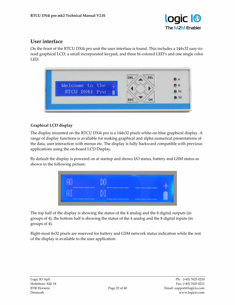
User interface
On the front of the RTCU DX4i pro unit the user interface is found. This includes a 144x32 easy-to-
read graphical LCD, a small incorporated keypad, and three bi-colored LED’s and one single color
LED.
Graphical LCD display
The display mounted on the RTCU DX4i pro is a 144x32 pixels white-on-blue graphical display. A
range of display functions is available for making graphical and alpha numerical presentations of
the data, user interaction with menus etc. The display is fully backward compatible with previous
applications using the on-board LCD Display.
By default the display is powered on at startup and shows I/O status, battery and GSM status as
shown in the following picture:
The top half of the display is showing the status of the 4 analog and the 8 digital outputs (in
groups of 4), the bottom half is showing the status of the 4 analog and the 8 digital inputs (in
groups of 4).
Right-most 8x32 pixels are reserved for battery and GSM network status indication while the rest
of the display is available to the user application.

RTCU DX4i pro mk2 Technical Manual V2.01
Logic IO ApS. Ph: (+45) 7625 0210
Holmboes Allé 14 Fax: (+45) 7625 0211
8700 Horsens Page 23 of 40 Email: [email protected]
Denmark www.logicio.com
States of the GSM network and battery are indicated with different icons and level indicators.
The following tables describe the states and their indications:
Status Icon
GSM off
GSM on GSM on and connected
GPRS connected
GSM signal levels are indicated with 4 bars – also known from many mobile phones. One bar
means low signal strength and four bars mean high signal strength. No signal strength bars mean
that the GSM module is powered up, but is not connected to a network service provider.
In the same manner the battery level is indicated with five levels; the fully filled battery icon
means fully charged and the empty battery icon means low battery level. While charging the
battery the battery icon is animated to show all the levels with a one second delay.
Power state of the display is saved in persistent memory, and the state will be restored when
power recycling or restarting the unit.
Please consult the RTCU-IDE on-line manual for more information about the use of the display.
Please note: The display will automatically turn off when the external power is removed.
The application can still access the display, and when the external power is restored, the display
content will automatically be visible again.
Keypad
The keypad consists of eight pushbuttons which are available on the front of the unit for the user
to interact with. These buttons are arranged in a logical way for easy use and each button is
marked with generally used symbols/text to fit almost every possible use.
The firmware button poll frequency is approximately 10 Hz.
Please consult the RTCU IDE on-line manual for more information about the use of the buttons.

RTCU DX4i pro mk2 Technical Manual V2.01
Logic IO ApS. Ph: (+45) 7625 0210
Holmboes Allé 14 Fax: (+45) 7625 0211
8700 Horsens Page 24 of 40 Email: [email protected]
Denmark www.logicio.com
LED Indicators
Three bi-colored (red and green) and a single yellow LED indicator are present on the front of the
unit (see graphical view).
Two bi-colored LED’s (A and B) are available to the user and the remaining two LED’s (S1 and S2)
are signaling the status and possible errors of the RTCU unit.
User LED A and B
LED A and B are composed of four individually controllable LEDs:
• LED named A on the front consists of LED 1 (green) and LED 2 (red).
• LED named B on the front consists of LED 3 (green) and LED 4 (red).
They are easily accessed from within the application program, and it is possible to mix the LED’s
to obtain a third color: yellow. Please consult the RTCU IDE documentation for more information.
RTCU DX4i pro mk2 Technical Manual V2.01
Logic IO ApS. Ph: (+45) 7625 0210
Holmboes Allé 14 Fax: (+45) 7625 0211
8700 Horsens Page 25 of 40 Email: [email protected]
Denmark www.logicio.com
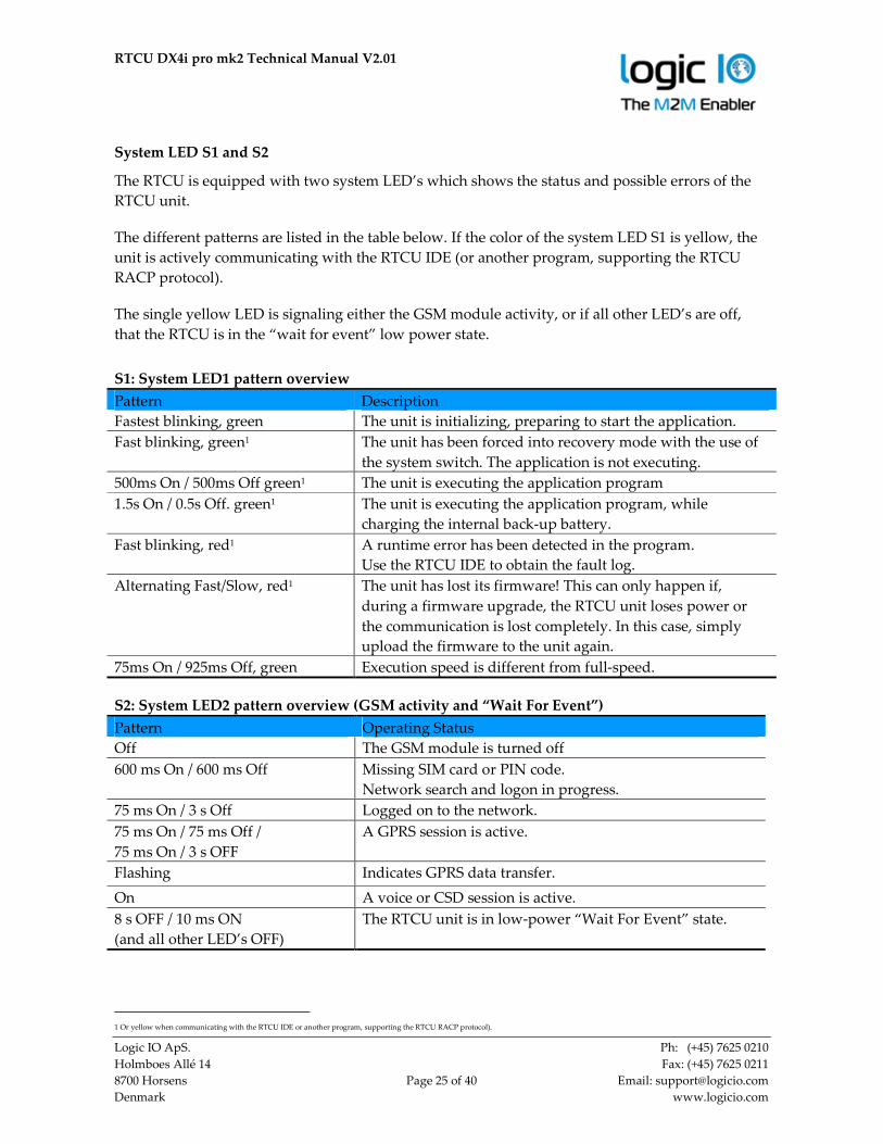
System LED S1 and S2
The RTCU is equipped with two system LED’s which shows the status and possible errors of the
RTCU unit.
The different patterns are listed in the table below. If the color of the system LED S1 is yellow, the
unit is actively communicating with the RTCU IDE (or another program, supporting the RTCU
RACP protocol).
The single yellow LED is signaling either the GSM module activity, or if all other LED’s are off,
that the RTCU is in the “wait for event” low power state.
S1: System LED1 pattern overview
Pattern Description
Fastest blinking, green The unit is initializing, preparing to start the application.
Fast blinking, green1 The unit has been forced into recovery mode with the use of
the system switch. The application is not executing.
500ms On / 500ms Off green1 The unit is executing the application program
1.5s On / 0.5s Off. green1 The unit is executing the application program, while
charging the internal back-up battery.
Fast blinking, red1 A runtime error has been detected in the program.
Use the RTCU IDE to obtain the fault log.
Alternating Fast/Slow, red1 The unit has lost its firmware! This can only happen if,
during a firmware upgrade, the RTCU unit loses power or
the communication is lost completely. In this case, simply
upload the firmware to the unit again.
75ms On / 925ms Off, green Execution speed is different from full-speed.
S2: System LED2 pattern overview (GSM activity and “Wait For Event”)
Pattern Operating Status
Off The GSM module is turned off
600 ms On / 600 ms Off Missing SIM card or PIN code.
Network search and logon in progress.
75 ms On / 3 s Off Logged on to the network.
75 ms On / 75 ms Off /
75 ms On / 3 s OFF
A GPRS session is active.
Flashing Indicates GPRS data transfer.
On A voice or CSD session is active.
8 s OFF / 10 ms ON
(and all other LED’s OFF)
The RTCU unit is in low-power “Wait For Event” state.
1 Or yellow when communicating with the RTCU IDE or another program, supporting the RTCU RACP protocol).
RTCU DX4i pro mk2 Technical Manual V2.01
Logic IO ApS. Ph: (+45) 7625 0210
Holmboes Allé 14 Fax: (+45) 7625 0211
8700 Horsens Page 26 of 40 Email: [email protected]
Denmark www.logicio.com
Switches
DIP-switch
The RTCU DX4i pro unit contains four dipswitches and three of them are available for the
application to use (fourth dipswitch is reserved for future use).
The dip switches are located on the top side of the unit for easy user access (see graphical view).
System switch (RST)
The RTCU DX4i pro unit contains a combined reset/diagnostic switch. This switch is accessible
from the front of the unit (see graphical view) It is necessary to use a small thin object with a
diameter of approx. 2 mm, for example a straightened-out paper clip for this purpose.
By activating the switch shortly the RTCU unit will do a complete reset, as if the power was
removed and reapplied.
If the reset switch is held down for approx. 3 seconds1 the unit will enter recovery mode2 where the
application will not be started. In recovery mode the system will automatically turn on the GSM
module to establish a connection to the GSM network and RTCU Gateway (if configured). This
method will also activate the unit when the unit is in power-down mode.
1 System LED S2 will flash three times when this state is entered.
2 System LED S1 will indicates this state by fast blinking green or yellow.

RTCU DX4i pro mk2 Technical Manual V2.01
Logic IO ApS. Ph: (+45) 7625 0210
Holmboes Allé 14 Fax: (+45) 7625 0211
8700 Horsens Page 27 of 40 Email: [email protected]
Denmark www.logicio.com
Internal Li-Ion battery
The RTCU contains an internal Li-Ion battery for operation even when the external power is absent
making it possible to report power loss etc. Please note that when external power is removed, the
unit will be powered down by default. This setting can be changed as documented in the RTCU
IDE documentation.
The graphical LCD display, digital and analog outputs will be disabled when a power fail occurs
as the internal battery cannot provide the supply voltage needed.
The battery charging is completely automated and handled internally by the RTCU unit – leaving
no need for user interaction. Different kinds of functions (Battery low, Charger enable, Charging
status, etc.) are available to the user application.
The charge current is relatively high, for a shorter charge time, as specified in the technical
specification. Make sure both power supply and cables can handle the high current.
The battery will be charged whenever a power fail has occurred to establish the capacity thus
making the battery ready for the next power fail. A maintenance charge will start every 20 days
after the last charge. This is to compensate for the battery self-discharge etc.
By default the battery cannot be charged above 45°C or below 0°C. The RTCU offers charging
down to -10 ˚C using a specialized algorithm to protect the battery.
If the temperature is above 45°C the charging will not start and will be postponed until it is below
this threshold.
The temperature has a very high influence on the battery capacity. At 0°C the capacity has
dropped to 60% of the initial capacity and it falls dramatically at lower temperatures.
The battery cycle (numbers of charges and discharges) also influences the capacity. After 300
cycles the capacity has dropped to approximately 80% of the initial capacity.
Warning
Misusing the RTCU unit may cause the built-in battery security circuit to be damaged.
• Do not place the RTCU unit in high temperature locations such as in direct sunlight or near
engines. Using the RTCU unit in this environment may result in loss of battery performance and a
shortened life expectancy.
• Do not expose the unit to water, salt water or allow the battery to get wet.
• Avoid strong impacts and shocks.
For more information regarding the environmental limitations, see “Specifications for RTCU DX4i
pro” below or consult the RTCU DX4i pro datasheet.

RTCU DX4i pro mk2 Technical Manual V2.01
Logic IO ApS. Ph: (+45) 7625 0210
Holmboes Allé 14 Fax: (+45) 7625 0211
8700 Horsens Page 28 of 40 Email: [email protected]
Denmark www.logicio.com
GSM / UMTS
The RTCU DX4i pro-3G offers a world-wide Penta band UMTS/HSPA engine with the following
features:
• UMTS: 800/850/900/1900/2100 MHz.
• GSM: 850/900/1800/1900 MHz.
• SMS (Text and PDU)
• UMTS release 7, category 6.
• CSD up to 14.4 Kbps.
• No voice/DTMF capability.
The RTCU DX4i pro-2G offers a world-wide capable Quad band GSM engine with the following
features:
• GSM: 850/900/1800/1900 MHz.
• SMS (Text and PDU)
• GPRS. Multislot class 12. Support for simultaneous Voice and GPRS (suspended.)
• Digitized voice (up to 182 seconds) and DTMF decoding.
• No CSD support.
SIM-Card
The RTCU DX4i pro unit contains a standard mini-SIM card reader which is located on the bottom
side of the unit (see graphical view) for easy of access. The SIM card reader has a push/push eject
system and a mechanical lock for secure installation of the SIM card.
Please refer to Appendix B for a SIM card installation guide.
It is possible to detect the state of both the SIM Insert and SIM lock status from the application.
Please consult the RTCU-IDE on-line manual for more information.
If the SIM-card is removed during GSM operation, the unit will be rejected from the GSM network
shortly after.
GSM / UMTS Antenna
The RTCU DX4i pro unit contains an SMA female connector for connecting a suitable antenna.
When installing the antenna, please make sure that the antenna is not in close proximity to metallic
parts or anything else that can influence the efficiency of the antenna.
Please consult the installation guide that follows the antenna.
RTCU DX4i pro mk2 Technical Manual V2.01
Logic IO ApS. Ph: (+45) 7625 0210
Holmboes Allé 14 Fax: (+45) 7625 0211
8700 Horsens Page 29 of 40 Email: [email protected]
Denmark www.logicio.com
SD-CARD reader
The RTCU DX4i pro unit has a standard SD-CARD reader which is located on the top side of the
unit (see graphical view) The RTCU DX4i pro supports a FAT file-system for standard PC-
compatibility with up to 32 GB capacity support.
The SD-CARD features a push/push eject system for reliable insertion and operation. Please refer
to Appendix C for an SD-Card installation guide.
Approved SD-CARDs
To ensure the highest performance and compatibility it is important to use SD-CARDs that has
been approved and tested by Logic IO.
The following Commercial Grade SD-CARDs from Sandisk have been approved for use:
Capacity Sandisk SKU
4GB SDSDB-004G-B35
8GB SDSDB-008G-B35
16GB SDSDB-016G-B35
32GB SDSDB-032G-B35
Commercial grade SD-CARDs can be used in applications where the limited write endurance is
acceptable - for example if the SD-CARD is often replaced. Commercial grade SD-CARDs should
not be used in applications where a potential failure on the media is considered mission critical.
For applications that uses the SD-CARD media extensively and where a failure is critical, it is
recommended to use approved Industrial Grade SD-CARDs.
Logic IO has approved and recommends industrial grade SD-CARDs from ATP that is available in
capacities from 512 MB to 32 GB.
ATP Industrial Grade SD/SDHC Cards are optimized for demanding industrial applications with
consistent performance in all conditions. ATP uses reliable SLC flash technology with a flash
endurance more than 20 times higher than commercial grade products with MLC flash.

RTCU DX4i pro mk2 Technical Manual V2.01
Logic IO ApS. Ph: (+45) 7625 0210
Holmboes Allé 14 Fax: (+45) 7625 0211
8700 Horsens Page 30 of 40 Email: [email protected]
Denmark www.logicio.com
The differences in write endurance between commercial grade MLC flash and ATP Industrial
grade SLC flash is quite remarkable for write-intensive applications:
Product Line Details Total Writeable Data
Prediction @ 1GB
Time Prediction
@ 500 writes a day (1GB)
ATP Industrial
Grade
SLC Flash
+ Advanced Wear Leveling
80,000GB
or
2,800,000 writes
5,740 days
or
15.7 years
Commercial
Grade
Grade A MLC
(2 bits per cell)
+ Advanced Wear Leveling
4,000GB
or
140,000 writes
280 days
Barcode
The barcode found on the DX4i pro unit contains the serial number.
The first three digits in the serial-number identify the unit type, and for the RTCU DX4i pro-3G
this unique code is 275 and the RTCU DX4i pro-2G it is 274.
The barcode format used: 2/5 Interleaved with Check Digit

RTCU DX4i pro mk2 Technical Manual V2.01
Logic IO ApS. Ph: (+45) 7625 0210
Holmboes Allé 14 Fax: (+45) 7625 0211
8700 Horsens Page 31 of 40 Email: [email protected]
Denmark www.logicio.com
Power consumption
Detailed information on the maximum power consumption of the RTCU DX4i pro unit in different
states and different supply voltages is listed below.
Maximum power consumption: unit running on external supply
8V 12V 36V
Unit active 85 55 20 mA
Unit active with GSM on* 120 65 30 mA GSM idle @ -63dBm*
Unit active with GPRS session*
(102kB file transfer over GPRS)
200 140 50 mA GSM @ -65dBm, LCD off,
Battery not charging*
Unit active with LCD on 95 70 50 mA
Unit active while charging 900 580 300 mA
Unit in power-down 0.8 0.6 0.3 mA Restart on DIN5, RTC
Unit in “wait for event” 0.8 0.6 0.3 mA Resume on DIN, RTC
Unit in “wait for event” 17 13 4 mA Resume on CAN
Unit in “wait for event” 11 8 3 mA Resume on RS232
Unit in “wait for event” 30 17 6 mA Resume on GSM activity
Note: Values marked with (*) is average and should be considered as guidelines as they may vary
depending on the GSM signal strength.
If the external power source is removed and the internal battery is enabled the power consumption
from the battery will be as listed below.
Maximum power consumption: unit running on internal battery
BAT
Unit active 90 mA
Unit active with GSM on 110 mA GSM idle @ -63dBm
Unit in power-down 0.8 mA Restart on DIN5, RTC
Unit in “wait for event” 0.8 mA Resume on DIN, RTC
Unit in “wait for event” 21 mA Resume on CAN
Unit in “wait for event” 13 mA Resume on RS232
Unit in “wait for event” 27 mA Resume on GSM activity
Note: Power consumption from a fully charged battery.

RTCU DX4i pro mk2 Technical Manual V2.01
Logic IO ApS. Ph: (+45) 7625 0210
Holmboes Allé 14 Fax: (+45) 7625 0211
8700 Horsens Page 32 of 40 Email: [email protected]
Denmark www.logicio.com
Appendix A – Unit configuration guide
The RTCU DX4i pro has many features and some of them require configuration by using hardware
jumpers inside the unit.
The following figure shows the location of the jumpers when the lid is removed. Blue lined boxes
show the default state of the jumpers. A dot on the corner of the 2-state jumpers indicates the pin
number 1.
JP8 JP9 JP10 JP11
.
.
JP1
JP14
JP
16
JP17
Daughter Board GSM Module
JP5 JP7 JP12 JP15 SER1
.
. .
JP4
JP
2
JP3
JP
6
. .
.
SM
A
RTCU DX4i pro mk2 Technical Manual V2.01
Logic IO ApS. Ph: (+45) 7625 0210
Holmboes Allé 14 Fax: (+45) 7625 0211
8700 Horsens Page 33 of 40 Email: [email protected]
Denmark www.logicio.com
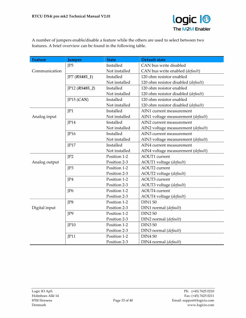
A number of jumpers enable/disable a feature while the others are used to select between two
features. A brief overview can be found in the following table.
Feature Jumper State Default state
JP5
Installed
Not installed
CAN bus write disabled
CAN bus write enabled (default)
JP7 (RS485_1) Installed
Not installed
120 ohm resistor enabled
120 ohm resistor disabled (default)
JP12 (RS485_2) Installed
Not installed
120 ohm resistor enabled
120 ohm resistor disabled (default)
Communication
JP15 (CAN) Installed
Not installed
120 ohm resistor enabled
120 ohm resistor disabled (default)
JP1 Installed
Not installed
AIN1 current measurement
AIN1 voltage measurement (default)
JP14 Installed
Not installed
AIN2 current measurement
AIN2 voltage measurement (default)
JP16 Installed
Not installed
AIN3 current measurement
AIN3 voltage measurement (default)
Analog input
JP17 Installed
Not installed
AIN4 current measurement
AIN4 voltage measurement (default)
JP2 Position 1-2
Position 2-3
AOUT1 current
AOUT1 voltage (default)
JP3 Position 1-2
Position 2-3
AOUT2 current
AOUT2 voltage (default)
JP4 Position 1-2
Position 2-3
AOUT3 current
AOUT3 voltage (default)
Analog output
JP6 Position 1-2
Position 2-3
AOUT4 current
AOUT4 voltage (default)
JP8 Position 1-2
Position 2-3
DIN1 S0
DIN1 normal (default)
JP9 Position 1-2
Position 2-3
DIN2 S0
DIN2 normal (default)
JP10 Position 1-2
Position 2-3
DIN3 S0
DIN3 normal (default)
Digital input
JP11 Position 1-2
Position 2-3
DIN4 S0
DIN4 normal (default)

RTCU DX4i pro mk2 Technical Manual V2.01
Logic IO ApS. Ph: (+45) 7625 0210
Holmboes Allé 14 Fax: (+45) 7625 0211
8700 Horsens Page 34 of 40 Email: [email protected]
Denmark www.logicio.com
JP5
Enable/disable write capability to the CAN bus. When the jumper is installed writing to the CAN
bus is disabled.
JP7, JP12 and JP15
Enables/disables the on-board 120 ohm line termination resistors.
CAN and RS485 communication requires as proper line termination value (assuming a CAT5 twisted
pair cable is used) and resistors in both ends of the bus. If the RTCU DX4i pro unit is used as
endpoint the relevant jumper can be installed.
By default the 120 ohm termination resistor is disabled.
JP1, JP14, JP16 and JP17
These jumpers are used to select between current and voltage input. With a jumper installed on the
relevant analog input it will measure current between 0-20mA.
By default the inputs measure voltage.
JP2, JP3, JP4 and JP6
These jumpers are used to select either current or voltage output. With the relevant jumper
installed on pin 1+2, the output is a current between 0-20mA. When installed on pin 2+3, the
output is a voltage.
By default the jumper is installed on pin 2+3 which means a voltage output.
JP8, JP9, JP10 and JP11
These select either normal or S0 input for DIN1-4. With the relevant jumper installed on pin 1+2,
the input is configured to S0. When installed on pin 2+3 the input is a normal digital input.
By default the jumper is installed on pin 2+3 and acts as normal digital input.
Follow the instructions on the next page on how to open the lid and change the jumper settings.

RTCU DX4i pro mk2 Technical Manual V2.01
Logic IO ApS. Ph: (+45) 7625 0210
Holmboes Allé 14 Fax: (+45) 7625 0211
8700 Horsens Page 35 of 40 Email: [email protected]
Denmark www.logicio.com
Opening the lid
1. Make sure no SD-CARD is inserted. Damage can be caused to the reader if forced open
with an SD-CARD inserted.
2. Place a screwdriver or a flat-tipped tool as shown in the picture and lift the screwdriver
handle upwards gently to unlock the lid.
3. Lift the lid carefully to the right. Be aware of the cables at the left end do not use force.
RTCU DX4i pro mk2 Technical Manual V2.01
Logic IO ApS. Ph: (+45) 7625 0210
Holmboes Allé 14 Fax: (+45) 7625 0211
8700 Horsens Page 36 of 40 Email: [email protected]
Denmark www.logicio.com
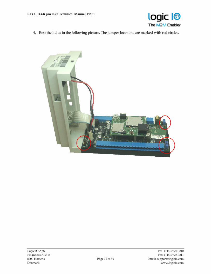
4. Rest the lid as in the following picture. The jumper locations are marked with red circles.

RTCU DX4i pro mk2 Technical Manual V2.01
Logic IO ApS. Ph: (+45) 7625 0210
Holmboes Allé 14 Fax: (+45) 7625 0211
8700 Horsens Page 37 of 40 Email: [email protected]
Denmark www.logicio.com
Closing the lid:
1. Begin by placing the left side of the lid onto the tap on the bottom part then close the lid
gently.
2. Make sure that the cables, especially the battery cable are placed correctly and not stuck to
the add-on board.
3. Push gently on the right side of the lid until you hear a click.
RTCU DX4i pro mk2 Technical Manual V2.01
Logic IO ApS. Ph: (+45) 7625 0210
Holmboes Allé 14 Fax: (+45) 7625 0211
8700 Horsens Page 38 of 40 Email: [email protected]
Denmark www.logicio.com
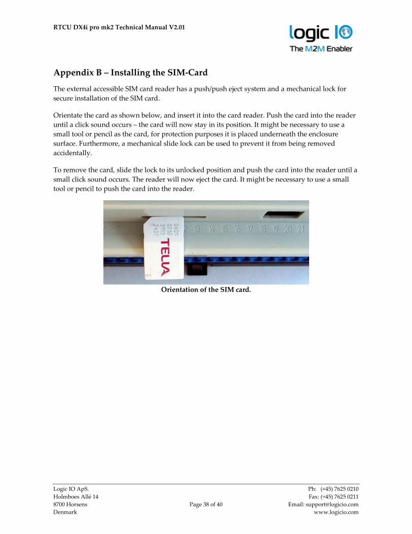
Appendix B – Installing the SIM-Card
The external accessible SIM card reader has a push/push eject system and a mechanical lock for
secure installation of the SIM card.
Orientate the card as shown below, and insert it into the card reader. Push the card into the reader
until a click sound occurs – the card will now stay in its position. It might be necessary to use a
small tool or pencil as the card, for protection purposes it is placed underneath the enclosure
surface. Furthermore, a mechanical slide lock can be used to prevent it from being removed
accidentally.
To remove the card, slide the lock to its unlocked position and push the card into the reader until a
small click sound occurs. The reader will now eject the card. It might be necessary to use a small
tool or pencil to push the card into the reader.
Orientation of the SIM card.

RTCU DX4i pro mk2 Technical Manual V2.01
Logic IO ApS. Ph: (+45) 7625 0210
Holmboes Allé 14 Fax: (+45) 7625 0211
8700 Horsens Page 39 of 40 Email: [email protected]
Denmark www.logicio.com
.
Appendix C – Installing the SD-CARD
To insert a card into the reader, orientate it as shown below and push the card into the reader until
a click sound occurs. Remove the card by pushing it into the reader until it clicks and the reader
will eject the card. Avoid removing the SD-CARD during access to the card.
SD-Card orientation
RTCU DX4i pro mk2 Technical Manual V2.01
Logic IO ApS. Ph: (+45) 7625 0210
Holmboes Allé 14 Fax: (+45) 7625 0211
8700 Horsens Page 40 of 40 Email: [email protected]
Denmark www.logicio.com
RTCU DX4i pro mk2 Specifications
Processor and Main-memory • Powerful 32-bit ST ARM7 processor. • 1088 KB fast execution RAM.
• 2304 KB Flash for firmware/application.
Storage • 3.5 MB persistent data flash. • 4 MB internal FAT32 flash drive. • 1 MB circular automatic datalogger. • 8 KB FRAM with fast access /
unlimited write endurance. • SD-CARD reader with up to 32 GB.
Digital/Analog Interface • 8 x digital solid-state digital output.
Max. 36 volt / 1.5 A per. channel. Short-circuit, ESD, Inductive kick-back protected up to 20 mH.
• 8 x digital inputs. Logic high: 6 to 40 VDC. Logic low: -5 to 3 VDC.
• 4 x IEC62053-31 Class A input. • Digital input #5 can be used as ignition. • 4 x analog inputs.
Range is 0..10VDC or 0..20 mA Resolution: 12 bit Precision: ±1.5% FSR @ 25°C
• 4 x analog outputs. Range is 0..10VDC or 0..20 mA Resolution: 10 bit Precision: ±1.5% FSR @ 25°C
• Protected against transients and low-pass filtered.
• Expandable I/O with MODBUS.
Communication • Full CAN2.0B with hardware filtering
and multi-speed support. • 1 x RS232 with control signals. • 1 x RS485 • 1 x shared RS232 / RS485. • 1-Wire bus.
GSM/UMTS • DX4i pro-3G: Penta-band UMTS/HSPA.
GSM: 850/900/1800/1900 MHz. UMTS: 800/850/900/1900/2100 Mhz. CSD with up to 14.4 Kbps.
• DX4i pro-2G: Quad-band GSM. 850/900/1800/1900 MHz. GPRS Class B, Multislot 12.
• SMS / PDU.
• DTMF decoding / transmission.
• Digitized voice playback / IVR.
• Mini-SIM 1.8/3 volt. • External SIM card-reader. • Optional Gemalto SIM-on-chip.
User Interaction • 144x32 pixels graphical/text display.
White-on-blue back-lit. • Keypad with 8 user defined keys. • Piezo Buzzer for user attention. • 3 x bi-colour LED. • Yellow status LED. • DIP-switches. • Reset / recovery switch.
Power Management • 5 execution speeds. • Wait for Event: Timer, Digital input,
RS232, CAN, GSM, power change state. • Wait for event, from: 600 uA@12V. • Supervision of supply voltage / type.
Environmental Specification • Operating temperature: -30 to 60°C. • Battery charge temperature:
-10 to 45 °C • Recommended storage temperature:
0 to 45°C. • Humidity: 5..90% (non condensing). • Ingress Protection: IP20 .
Physical Characteristics • Encapsulation:
9 Module M36 DIN-rail. • Approx. 430 gram without accessories. • W 157 x H 86 x D 58 mm.
(wihout SMA and screw-terminals).
Electrical Specification. • Operating voltage is 8 to 36 VDC. • Short and reverse power protected.
Warranty • Two-years return to factory parts and
labor. • Optional warranty up to 5 years.
(restrictions apply).
Approvals • CE. EU EMC directive 2004/108/EU. • Applied R&TTE directive. • GSM engine: CE/GCF/FCC/PTCRB.
Battery and Charger • On-board 2Ah (nominal) Li-Ion battery. • Intelligent charger with temperature
throttle and sub-zero degrees support. • On-board temperature sensor.
External Interfaces. • SIM-card slot for micro-SIM with lock and
presence detection. • SD-CARD slot with presence and write
protect detection. • Audio out for digitized voice playback. • LED indicators and DIP switches. • Reset/recovery switch, • Two-part pluggable connector for:
Power, I/O, RS485, 1Wire. CAN. • TE-Connectivity ”Mate’n’Lock’ for:
RS232 / DCOUT. • RJ45 for RS232 (EIA-561) • SMA Female connector for GSM. • Mini USB-B as service port.
* * * * END OF DOCUMENT * * * *
Technical data are subject to changes.