rte-200 & rte-300 refrigerated baths/circulators ... · the rte refrigerated circulators are...
TRANSCRIPT
- 27 -
Instruction and Operation Manual
NESLAB onlineProduct Service Information, Electronic Catalog,Applications Notes, MSDS Forms, e-mail.
(603)427-2490Set modem to 8-N-1 protocol, 1200 - 14400 baud
Voice Info: (800) 4-NESLAB
Comments on this manual can be sent to:
or visit our Web page at:
http://www.neslabinc.com
RTE-200 & RTE-300Refrigerated
Baths/Circulators
NESLAB Manual P/N U00094
Rev. 03/05/97
- 1 -
RTE-200 & RTE-300 Refrigerated CirculatorInstruction and Operation Manual
Table of Contents
PrefaceCompliance ............................................................ 2Unpacking .............................................................. 2Warranty ................................................................ 2After-Sale Support .................................................. 2
SafetyWarnings................................................................ 3
General InformationDescription ............................................................. 4Specifications ........................................................ 4
InstallationSite ........................................................................ 5Electrical Requirements ........................................ 5Plumbing Requirements ........................................ 6Fluids .................................................................... 7Filling Requirements ............................................. 7
ControllersControllers.............................................................. 8Start Up .................................................................. 8Digital Controller ..................................................... 8Microprocessor Controller .................................... 13RS-232 Serial Communications Report ................ 21High Temperature/Low Liquid Level Safety .......... 22DB9 Connector Pinouts ........................................ 23
Maintenance &Troubleshooting
Cleaning ............................................................... 24Algae .................................................................... 24Checklist .............................................................. 24
WarrantyWarranty .............................................................. 26
- 2 -
Preface
ComplianceProducts tested and found to be in compliance with the requirements definedin the EMC standards defined by 89/336/EEC as well as Low Voltage Direc-tive (LVD) 73/23/EEC can be identified by the CE label on the rear of the unit.The testing has demonstrated compliance with the following directives:
LVD, 73/23/EEC Complies with UL 3101-1:93
EMC, 89/336/EEC EN 55011, Class A VerificationEN 50082-1:1992IEC 1000-4-2:1995IEC 1000-4-3:1994IEC 1000-4-4:1995
For any additional information refer to the Letter of Compliance that shippedwith the unit (Declaration of Conformity).
UnpackingRetain all cartons and packing material until the unit is operated and found tobe in good condition. If the unit shows external or internal damage, or doesnot operate properly, contact the transportation company and file a damageclaim. Under ICC regulations, this is your responsibility.
WarrantyUnits have a warranty against parts and workmanship for one full year fromdate of shipment. See back page for more details.
After-saleSupport
NESLAB is committed to customer service both during and after the sale. Ifyou have questions concerning the operation of your unit, contact our SalesDepartment. If your unit fails to operate properly, or if you have questionsconcerning spare parts or Service Contracts, contact our Service
Department. Before calling, please obtain the following information from theunit’s serial number label:
- BOM number ________________________________
- Serial number ________________________________
- 3 -
Safety
WarningsMake sure you read and understand all instructions and safety precautionslisted in this manual before installing or operating your unit. If you have anyquestions concerning the operation of your unit or the information in thismanual, contact our Sales Department.
Performance of installation, operation, or maintenance proceduresother than those described in this manual may result in a hazardoussituation and may void the manufacturer's warranty.
Transport the unit with care. Sudden jolts or drops can damage therefrigeration lines.
Observe all warning labels.
Never remove warning labels.
Never operate damaged or leaking equipment.
Never operate the unit without fluid in the circulator.
Use tap water unless operating above 80°C. Above 80°C use Dow 200silicon oil.
For 220-240 volt units supplied without a line cord, use a harmonized(HAR) grounded 3-conductor cord, type H05VV-F. A suitable cord end isneeded for connecting to the equipment (see unit socket) and must termi-nate with an IEC approved plug for proper power supply connection.
Always turn off the unit and disconnect the line cord from the powersource before performing any service or maintenance procedures, orbefore moving the unit.
Always empty the circulator before moving the unit.
Never operate equipment with damaged line cords.
Refer service and repairs to a qualified technician.
In addition to the safety warnings listed above, warnings are postedthroughout the manual. These warnings are designated by an exclamationmark inside an equilateral triangle with text highlighted in bold print. Readand follow these important instructions. Failure to observe these instructionscan result in permanent damage to the unit, significant property damage,personal injury or death.
- 4 -
General Information
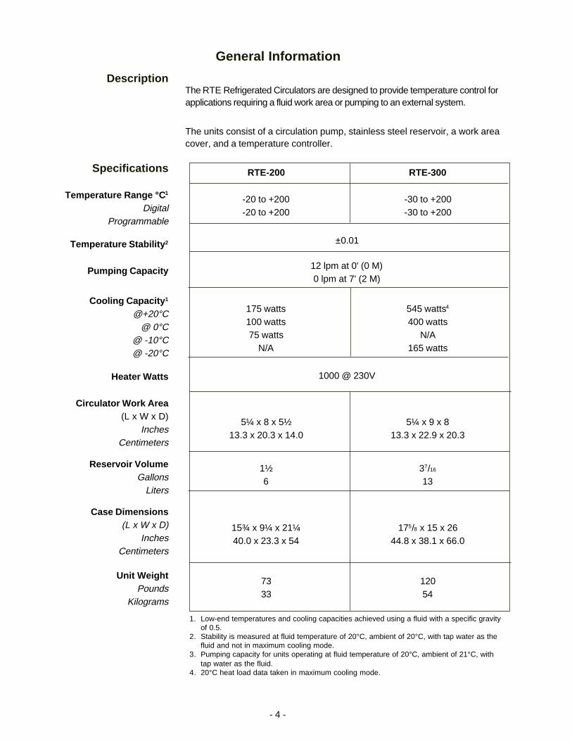
DescriptionThe RTE Refrigerated Circulators are designed to provide temperature control forapplications requiring a fluid work area or pumping to an external system.
The units consist of a circulation pump, stainless steel reservoir, a work areacover, and a temperature controller.
Specifications
Temperature Range °C 1
DigitalProgrammable
Temperature Stability 2
Pumping Capacity
Cooling Capacity 1
@+20°C@ 0°C
@ -10°C@ -20°C
Heater Watts
Circulator Work Area(L x W x D)
InchesCentimeters
Reservoir VolumeGallons
Liters
Case Dimensions(L x W x D)
InchesCentimeters
Unit WeightPounds
Kilograms
RTE-200 RTE-300
-20 to +200 -30 to +200-20 to +200 -30 to +200
±0.01
12 lpm at 0' (0 M)0 lpm at 7' (2 M)
175 watts 545 watts4
100 watts 400 watts75 watts N/A
N/A 165 watts
1000 @ 230V
5¼ x 8 x 5½ 5¼ x 9 x 813.3 x 20.3 x 14.0 13.3 x 22.9 x 20.3
1½ 37/16
6 13
15¾ x 9¼ x 21¼ 175/8 x 15 x 2640.0 x 23.3 x 54 44.8 x 38.1 x 66.0
73 12033 54
1. Low-end temperatures and cooling capacities achieved using a fluid with a specific gravityof 0.5.
2. Stability is measured at fluid temperature of 20°C, ambient of 20°C, with tap water as thefluid and not in maximum cooling mode.
3. Pumping capacity for units operating at fluid temperature of 20°C, ambient of 21°C, withtap water as the fluid.
4. 20°C heat load data taken in maximum cooling mode.
- 5 -
Installation
Site
Never place the unit in a location where excessive heat, moisture, orcorrosive materials are present.
Locate the unit on a sturdy table or bench top. Ambient temperatures shouldbe inside the range of +50°F to +89.6°F (+10°C to +32°C).
The unit has an air-cooled refrigeration system. Air is drawn through thefront panel and discharged through the rear panel. The unit must bepositioned so the air intake and discharge are not impeded. A minimumclearance of 12 inches (30 centimeters) at the front and rear of the unit isnecessary for adequate ventilation. Inadequate ventilation will reducecooling capacity and, in extreme cases, can cause compressor failure.
Excessively dusty areas should be avoided and a periodic cleaning scheduleshould be instituted (see Cleaning).
ElectricalRequirements
Line voltage may be easily accessible inside the pump/control box.Always unplug the unit prior to removing the pump/control box cover.
The unit construction provides extra protection against the risk ofelectric shock by grounding appropriate metal parts. The extra protec-tion may not function unless the power cord is connected to a properlygrounded outlet. It is the user's responsibility to assure a proper groundconnection is provided.
For 220 - 240 volt units supplied without a line cord, use a harmonized(HAR) grounded 3-conductor cord, type H 0 5 V V - F . A suitable cordend is required for connecting to the equipment (see unit socket) andmust terminate with an IEC approved plug for proper connection topower supply.
Refer to the serial number label on the rear of the unit to identify the specificelectrical requirements of your unit.
Ensure the voltage of the power source meets the specified voltage, ±10%.
- 6 -
PlumbingRequirements
Ensure the unit is off before connecting tubing to the unit.
Hose ConnectionsThe pump connections are located at the rear of the pump box and arelabelled INLET and OUTLET. The connections are capped with stainlesssteel serrated plugs.
The pump lines have ¼ inch male pipe threads for mating with standardplumbing fittings. For your convenience two stainless steel adapters, ¼ inchfemale pipe thread to 3/8 inch O.D. serrated fitting, are provided. (To assureproper fit, they should be installed using Teflon® tape around the threads.)
Flexible tubing, if used, should be of heavy wall or reinforced construction.Make sure all tubing connections are securely clamped. Avoid runningtubing near radiators, hot water pipes, etc. If substantial lengths of tubingare necessary, insulation may be required to prevent loss of cooling capacity.
It is important to keep the distance between the unit and the external systemas short as possible, and to use the largest diameter tubing practical. Tubingshould be straight and without bends. If diameter reductions must be made,make them at the inlet and outlet of the external system, not at the unit.
If substantial lengths of cooling lines are required, they should be pre-filledwith bath fluid before connecting them to the unit. This will ensure that aadequate amount of fluid will be in the circulator once it is in operation.
PumpingThe pump is designed to deliver a flow of 12 liters/minute at 0 feet head. Toprevent external circulation, the INLET and OUTLET lines are capped. Thecaps must be removed when external circulation is required.
To properly secure the external hose connections to the unit, wrap Teflon®
tape around the pipe line threads before installation. Once the hose connec-tions are made, the pump must be properly plumbed to an external system. Itis important the circulator is not in operation until all plumbing is complete.
If the circulator is not used for external circulation, make sure the stainlesssteel caps are in place prior to operating the circulator.
- 7 -
Fluids
Never use flammable or corrosive fluids with this unit.
Tap water is the recommended fluid for operation from 7°C to +80°C.
Above +80°C, Dow 200® silicon oil is recommended.
For operation below 7°C, a 50/50 mixture, by volume, of tap water andlaboratory grade ethylene glycol is suggested.
Never use pure ethylene glycol as a fluid. A minimum 80/20 mixture ofEthylene Glycol and tap water is allowed.
FillingRequirements
The circulator work area has a high and low level marker to guide filling. Themarkers are 1 inch horizontal slits located in the center of the stainless steelbaffle separating the work area and the pump assembly. The correct fluidlevel falls between these two markers. The heating and cooling coils will beexposed and may become damaged if the correct fluid level is not provided.
When pumping to an external system, keep extra fluid on hand to maintainthe proper level in both the circulating lines and external system.
Never run the unit when the work area is empty.
- 8 -
Controllers
ControllersTwo temperature controllers are available with the unit: Digital and Micropro-cessor. This section explains the installation and operation of each.
Start UpBefore starting the unit, check all electrical and plumbing connections andmake sure the work area has been properly filled with fluid.
To start any unit place the I/O switch on the side of the controller to theI (power on) position. The pump will start and the controller display will light.
NOTE: When the unit is shut off, wait approximately five minutes beforerestarting. This allows time for the refrigeration pressures to equalize. If thepressures are not allowed to equalize, the compressor will short-cycle (click-ing sound) and no cooling will occur.
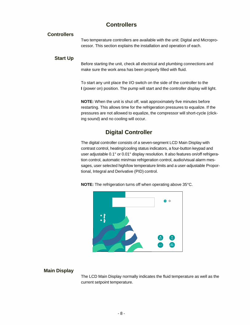
Digital Controller
The digital controller consists of a seven-segment LCD Main Display withcontrast control, heating/cooling status indicators, a four-button keypad anduser adjustable 0.1° or 0.01° display resolution. It also features on/off refrigera-tion control, automatic min/max refrigeration control, audio/visual alarm mes-sages, user selected high/low temperature limits and a user-adjustable Propor-tional, Integral and Derivative (PID) control.
NOTE: The refrigeration turns off when operating above 35°C.
Main DisplayThe LCD Main Display normally indicates the fluid temperature as well as thecurrent setpoint temperature.
- 9 -
Key Button DefinitionSET is used to change the current value or status of a function within thesoftware.
ENTER is used to "accept" the new value or function.
YES is used to confirm a question asked within the software.
NO is used to reject or change a function with in the software.
NEXT is used as a means to quickly scroll through the software loops andsettings.
The up and down arrow keys are used to change a numeric value.
Changing SetpointTo change the setpoint, press SET. The current setpoint will flash. Use thekeys to change the setpoint. Scrolling includes three speed acceleration.Press ENTER to accept the new setpoint. NOTE: If you do not pressENTER, a time out will occur 30 seconds after the last key is pressed and theold setpoint will be used.
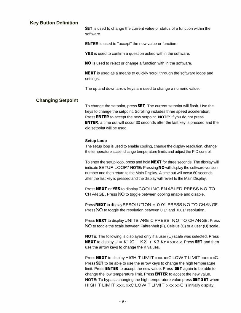
Setup LoopThe setup loop is used to enable cooling, change the display resolution, changethe temperature scale, change temperature limits and adjust the PID control.
To enter the setup loop, press and hold NEXT for three seconds. The display willindicate SETUP LOOP? NOTE: Pressing NO will display the software versionnumber and then return to the Main Display. A time out will occur 60 secondsafter the last key is pressed and the display will revert to the Main Display.
Press NEXT or YES to display COOLING ENABLED PRESS NO TOCHANGE. Press NO to toggle between cooling enable and disable.
Press NEXT to display RESOLUTION = 0.01 PRESS NO TO CHANGE.Press NO to toggle the resolution between 0.1° and 0.01° resolution.
Press NEXT to display UNITS ARE C PRESS NO TO CHANGE. PressNO to toggle the scale between Fahrenheit (F), Celsius (C) or a user (U) scale.
NOTE: The following is displayed only if a user (U) scale was selected. PressNEXT to display U = K1(C + K2) + K3 Kn=xxx.x. Press SET and thenuse the arrow keys to change the K values.
Press NEXT to display HIGH T LIMIT xxx.xxC LOW T LIMIT xxx.xxC.Press SET to be able to use the arrow keys to change the high temperaturelimit. Press ENTER to accept the new value. Press SET again to be able tochange the low temperature limit. Press ENTER to accept the new value.NOTE: To bypass changing the high temperature value press SET SET whenHIGH T LIMIT xxx.xxC LOW T LIMIT xxx.xxC is initially display.
- 10 -
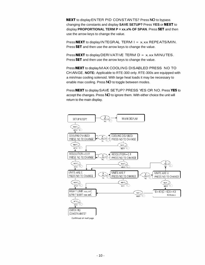
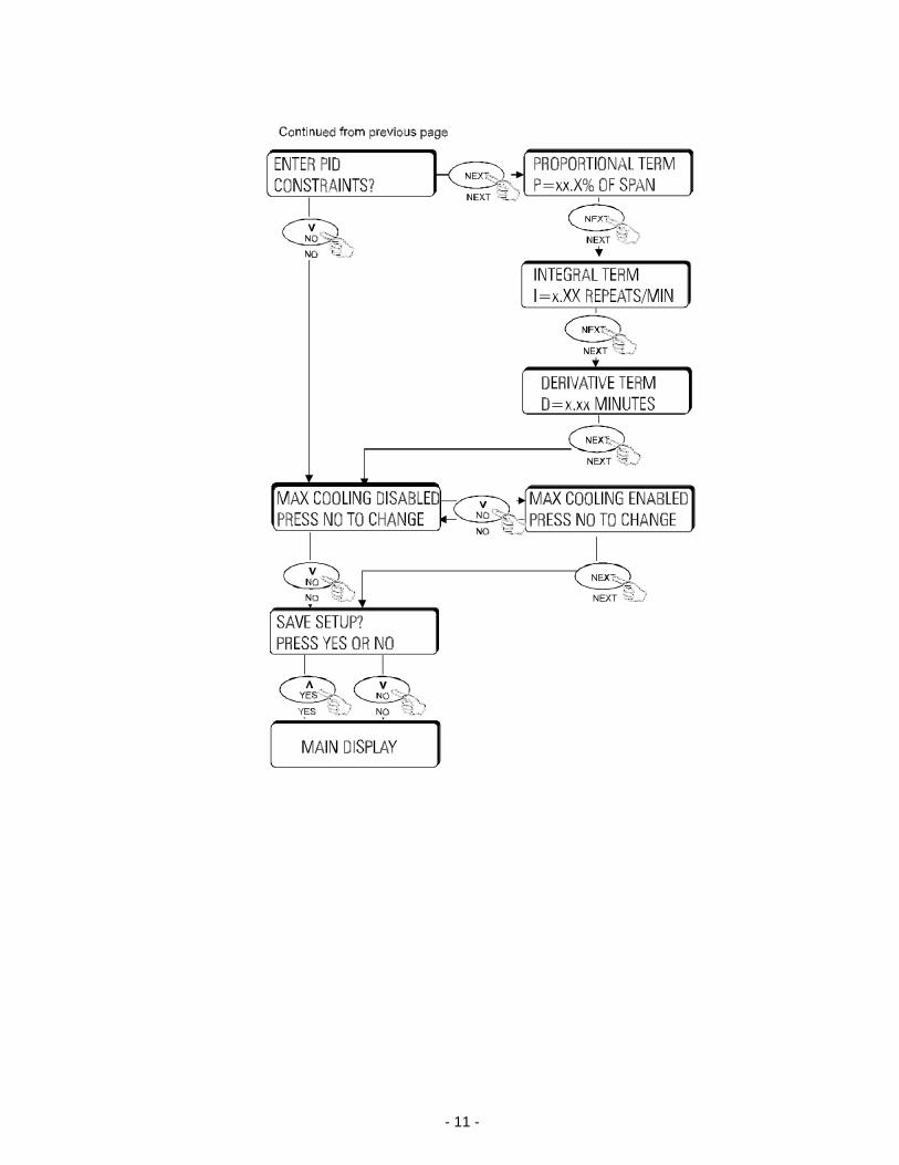
NEXT to display ENTER PID CONSTANTS? Press NO to bypasschanging the constants and display SAVE SETUP? Press YES or NEXT todisplay PROPORTIONAL TERM P = xx.x% OF SPAN . Press SET and thenuse the arrow keys to change the value.
Press NEXT to display INTEGRAL TERM I = x.xx REPEATS/MIN.Press SET and then use the arrow keys to change the value.
Press NEXT to display DERIVATIVE TERM D = x.xx MINUTES.Press SET and then use the arrow keys to change the value.
Press NEXT to display MAX COOLING DISABLED PRESS NO TOCHANGE. NOTE: Applicable to RTE-300 only. RTE-300s are equipped witha min/max cooling solenoid. With large heat loads it may be necessary toenable max cooling. Press NO to toggle between modes.
Press NEXT to display SAVE SETUP? PRESS YES OR NO. Press YES toaccept the changes. Press NO to ignore them. With either choice the unit willreturn to the main display.
- 11 -
- 12 -
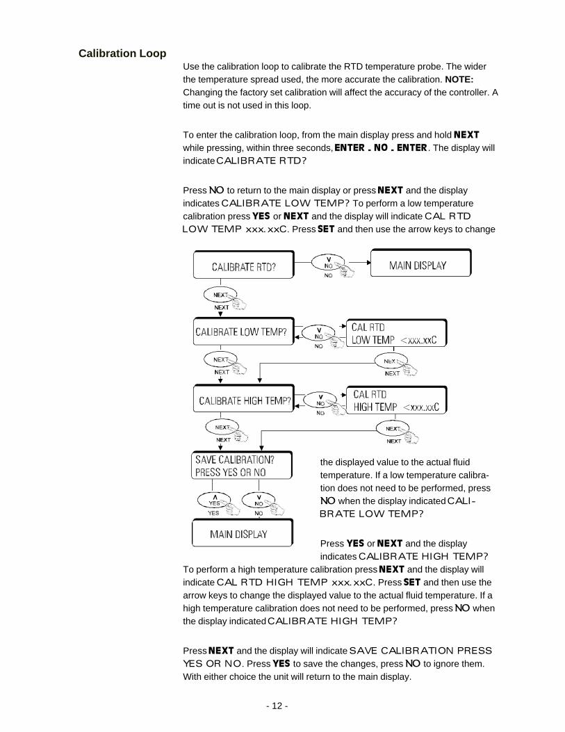
Calibration LoopUse the calibration loop to calibrate the RTD temperature probe. The widerthe temperature spread used, the more accurate the calibration. NOTE:Changing the factory set calibration will affect the accuracy of the controller. Atime out is not used in this loop.
To enter the calibration loop, from the main display press and hold NEXTwhile pressing, within three seconds, ENTER - NO - ENTER. The display willindicate CALIBRATE RTD?
Press NO to return to the main display or press NEXT and the displayindicates CALIBRATE LOW TEMP? To perform a low temperaturecalibration press YES or NEXT and the display will indicate CAL RTDLOW TEMP xxx.xxC. Press SET and then use the arrow keys to change
the displayed value to the actual fluidtemperature. If a low temperature calibra-tion does not need to be performed, pressNO when the display indicated CALI-BRATE LOW TEMP?
Press YES or NEXT and the displayindicates CALIBRATE HIGH TEMP?
To perform a high temperature calibration press NEXT and the display willindicate CAL RTD HIGH TEMP xxx.xxC. Press SET and then use thearrow keys to change the displayed value to the actual fluid temperature. If ahigh temperature calibration does not need to be performed, press NO whenthe display indicated CALIBRATE HIGH TEMP?
Press NEXT and the display will indicate SAVE CALIBRATION PRESSYES OR NO. Press YES to save the changes, press NO to ignore them.With either choice the unit will return to the main display.
- 13 -
Microprocessor Controller
The microprocessor controller consists of a seven-segment LCD with con-trast control, heating/cooling status indicators, a 12-button keypad and useradjustable 0.1° or 0.01° temperature display resolution, external sensor inputwith automatic switching in the event of external sensor failure. It also fea-tures automatic on/off refrigeration control, automatic min/max refrigerationcontrol, audio/visual alarm messages, automatic fixed temperature limit, userselected high/low temperature limits, programmable temperature profile,RS-232 communication and a user-adjustable Proportional, Integral andDerivative (PID) control.
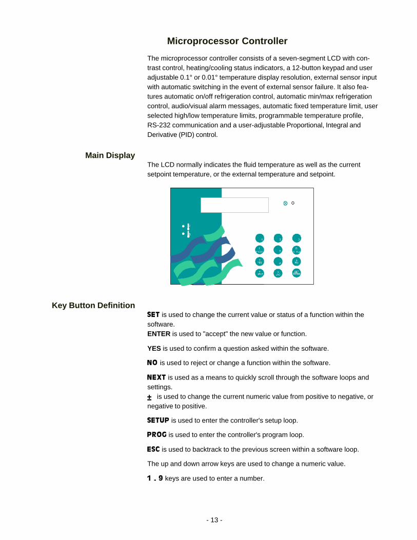
Main DisplayThe LCD normally indicates the fluid temperature as well as the currentsetpoint temperature, or the external temperature and setpoint.
Key Button DefinitionSET is used to change the current value or status of a function within thesoftware.ENTER is used to "accept" the new value or function.
YES is used to confirm a question asked within the software.
NO is used to reject or change a function within the software.
NEXT is used as a means to quickly scroll through the software loops andsettings.± is used to change the current numeric value from positive to negative, ornegative to positive.
SETUP is used to enter the controller's setup loop.
PROG is used to enter the controller's program loop.
ESC is used to backtrack to the previous screen within a software loop.
The up and down arrow keys are used to change a numeric value.
1 - 9 keys are used to enter a number.
- 14 -
Changing SetpointTo change the setpoint, press SET ENTER. The current setpoint will flash. Ifthe number to be entered is negative, press the +/- key. Otherwise, enterthe most significant digit of the number. The digit will appear in the leastsignificant decimal position. As each digit is entered the previously entereddigits will shift up in significance. Enter trailing zeros as needed to obtain thedesired order of magnitude. Press SET ENTER to accept the new setpoint.NOTE: If you do not press SET ENTER, a time out will occur 30 seconds afterthe last key is pressed and the old setpoint will be used.
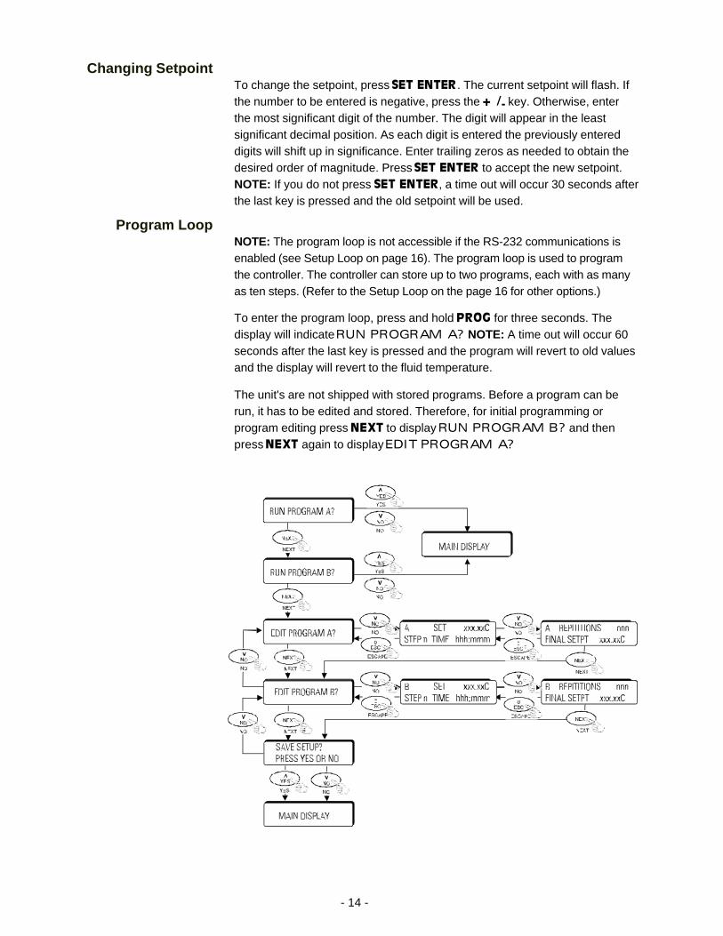
Program LoopNOTE: The program loop is not accessible if the RS-232 communications isenabled (see Setup Loop on page 16). The program loop is used to programthe controller. The controller can store up to two programs, each with as manyas ten steps. (Refer to the Setup Loop on the page 16 for other options.)
To enter the program loop, press and hold PROG for three seconds. Thedisplay will indicate RUN PROGRAM A? NOTE: A time out will occur 60seconds after the last key is pressed and the program will revert to old valuesand the display will revert to the fluid temperature.
The unit's are not shipped with stored programs. Before a program can berun, it has to be edited and stored. Therefore, for initial programming orprogram editing press NEXT to display RUN PROGRAM B? and thenpress NEXT again to display EDIT PROGRAM A?
- 15 -
Press YES or NEXT to display the temperature, step number and time dura-tion. Steps start at 0. Press SET ENTER and using the keypad enter thesetpoint temperature. Press SET ENTER. Press SET ENTER and enter thenumber of hours. Press SET ENTER. Press SET ENTER and enter the numberof minutes. Press SET ENTER.
NOTE: Step time starts when the fluid temperature gets within 0.5°C of thecurrent setpoint.
The display will increment to step 1. Repeat the procedure for the totalnumber of desired steps. To skip a number press SET ENTER twice. To enda program with fewer than ten steps, enter 0 hours and 0 minutes.
Press NEXT to display the number of program repetitions. Press SET ENTERand enter the number of reps. Press SET ENTER. Press SET ENTER and enterthe final setpoint for the program. Press SET ENTER.
Press NEXT to display EDIT PROGRAM B? Use the same procedures.
Press NEXT to display SAVE PROGRAMS? Press YES to save or NO toignore. The unit returns to the main display.
With program(s) saved, when the display reads RUN PROGRAM press-ing YES will start the program, pressing NO will stop it. With either choice theunit returns to the main display.
- 16 -
Setup LoopNOTE: The setup loop is not accessible if a program is running. If RS-232communications is enabled, only the RS-232 portion of the setup loop isactive.
The setup loop is used to enable refrigeration, change the display resolution,change the temperature scale, change temperature limits, adjust the PIDcontrol, select internal or external probe, enter the maximum internal andexternal temperature difference and enable RS-232 communications.
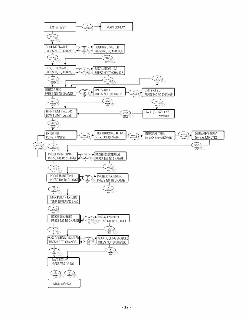
To enter the setup loop from the main display, press and hold SETUP forthree seconds. The display will indicate SETUP LOOP? NOTE: A time outwill occur 60 seconds after the last key is pressed and the display will revertto the fluid temperature.
Press YES or NEXT to display REFRIGERATION OFF WHEN SETPOINT >xxC . Use the keypad to display the desired temperature.
The refrigeration system is not designed to operate above 35°C.
Press NEXT to display RESOLUTION = 0.01 PRESS NO TO CHANGE .Press NO to toggle between 0.1°C and 0.01°C display resolution, press YESor NEXT to maintain the displayed resolution.
Press NEXT to display UNITS ARE C PRESS NO TO CHANGE . Press NOto toggle between temperature scales Celsius (C), Fahrenheit (F) and a userdefined (U) scale. Press YES or NEXT to maintain the displayed scale.
NOTE: The following is displayed only if a user (U) scale was selected. PressNEXT to display U = K1(C + K2) + K3 Kn=xxx.x . Press SET ENTER and usethe keypad to change the values.
Press NEXT to display HIGH T LIMIT xxx.xxC LOW T LIMIT xxx.xxC . PressSET ENTER and enter the high temperature limit. Press SET ENTER toaccept the new value. Press SET ENTER again to be able to change the lowtemperature limit. Press SET ENTER to accept the new value. NOTE: Tobypass changing the high temperature value press SET ENTER twice whenHIGH T LIMIT xxx.xxC LOW T LIMIT xxx.xxC is initially display.
Press NEXT to display ENTER PID CONSTANTS? Press NO to bypasschanging the constants and display PROBE IS INTERNAL PRESS NO TOCHANGE or press NEXT to display PROPORTIONAL TERM P = xx.x% OFSPAN. Press SET ENTER and use the keypad to enter the desired value.
Press NEXT to display INTEGRAL TERM I = x.xx REPEATS/MIN . PressSET ENTER and use the keypad to enter the desired value.
- 17 -
- 18 -
Press NEXT to display DERIVATIVE TERM D = x.xx MINUTES.Press SET ENTER and use the keypad to enter the desired value.
Press NEXT to display PROBE IS INTERNAL PRESS NO TO CHANGE .Press NO to toggle between internal or external probe or press YES orSET ENTER to use the displayed probe.
Press NEXT to display MAX INTERN EXTERN TEMP DIFFERENCExxC. This is the maximum temperature difference between the internal andexternal probes. Use this to prevent the unit from running out of control in theevent the external probe is accidently removed from the fluid. Press SETENTER and use the keypad to enter the desired value.
Press NEXT to display RS232 IS DISABLED PRESS NO TOCHANGE. Press NO to toggle between disabled and enabled or press YESor SET ENTER to use the displayed mode.
Press NEXT to display MAX COOLING DISABLED PRESS NO TOCHANGE. NOTE: Applicable to RTE-300s only. RTE-300s are equippedwith a min/max cooling solenoid. With large heat loads it may be necessary toenable max cooling. Press NO to toggle between disabled and enabled orpress YES or SET ENTER to use the displayed mode.
Press NEXT to display SAVE SETUP? PRESS YES OR NO. PressYES to accept the changes. Press NO to ignore them. The unit will return tothe main display.
- 19 -
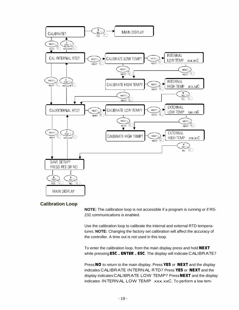
Calibration LoopNOTE: The calibration loop is not accessible if a program is running or if RS-232 communications is enabled.
Use the calibration loop to calibrate the internal and external RTD tempera-tures. NOTE: Changing the factory set calibration will affect the accuracy ofthe controller. A time out is not used in this loop.
To enter the calibration loop, from the main display press and hold NEXTwhile pressing ESC - ENTER - ESC. The display will indicate CALIBRATE?
Press NO to return to the main display. Press YES or NEXT and the displayindicates CALIBRATE INTERNAL RTD? Press YES or NEXT and thedisplay indicates CALIBRATE LOW TEMP? Press NEXT and the displayindicates INTERNAL LOW TEMP xxx.xxC. To perform a low tem-
- 20 -
perature calibration press SET and use the keypad to change the value. If thevalues did not need to be changed, press NO when the display indicatedCALIBRATE LOW TEMP?
Press NEXT and the display indicates CALIBRATE HIGH TEMP? PressNEXT and the display indicates INTERNAL HIGH TEMP xxx.xxC. Toperform a high temperature calibration press SET and use the keypad tochange the value. If the values did not need to be changed, press NO when thedisplay indicated CALIBRATE HIGH TEMP?
Press NEXT and the display indicates CALIBRATE EXTERNAL RTD?Press NEXT and the display indicates CALIBRATE LOW TEMP? PressNEXT and the display indicates EXTERNAL LOW TEMP xxx.xxC. Toperform a low temperature calibration press SET and use the keypad to changethe value. If the values did not need to be changed, press NO when the displayindicated CALIBRATE LOW TEMP?
Press NEXT and the display indicates CALIBRATE HIGH TEMP? PressNEXT and the display indicates EXTERNAL HIGH TEMP xxx.xxC. Toperform a high temperature calibration press SET and use the keypad tochange the value. If the values did not need to be changed, press NO whenthe display indicated CALIBRATE HIGH TEMP?
Press NEXT and the display will indicate SAVE CALIBRATION? PRESSYES OR NO. Press YES to save the changes, press NO to ignore them.The unit will return to the main display.
- 21 -
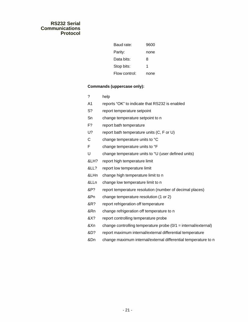
RS232 SerialCommunications
Protocol
Baud rate: 9600
Parity: none
Data bits: 8
Stop bits: 1
Flow control: none
Commands (uppercase only):
? help
A1 reports “OK” to indicate that RS232 is enabled
S? report temperature setpoint
Sn change temperature setpoint to n
F? report bath temperature
U? report bath temperature units (C, F or U)
C change temperature units to °C
F change temperature units to °F
U change temperature units to °U (user defined units)
&LH? report high temperature limit
&LL? report low temperature limit
&LHn change high temperature limit to n
&LLn change low temperature limit to n
&P? report temperature resolution (number of decimal places)
&Pn change temperature resolution (1 or 2)
&R? report refrigeration off temperature
&Rn change refrigeration off temperature to n
&X? report controlling temperature probe
&Xn change controlling temperature probe (0/1 = internal/external)
&D? report maximum internal/external differential temperature
&Dn change maximum internal/external differential temperature to n
- 22 -
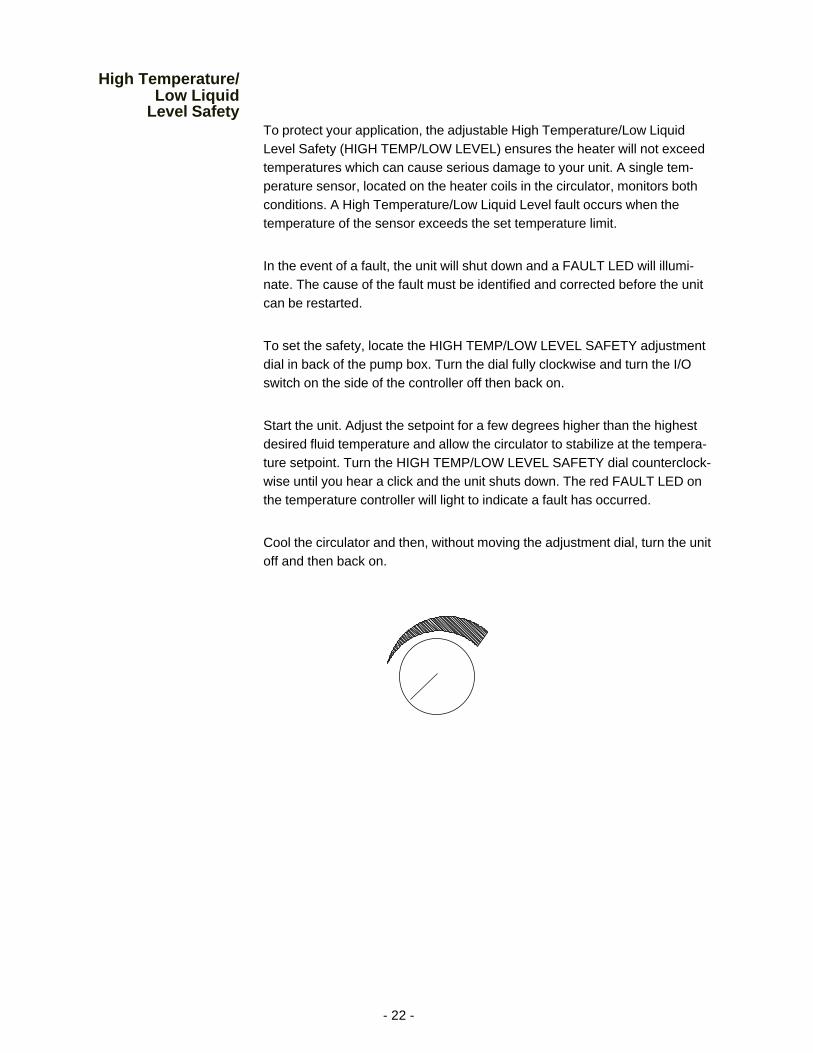
High Temperature/Low Liquid
Level SafetyTo protect your application, the adjustable High Temperature/Low LiquidLevel Safety (HIGH TEMP/LOW LEVEL) ensures the heater will not exceedtemperatures which can cause serious damage to your unit. A single tem-perature sensor, located on the heater coils in the circulator, monitors bothconditions. A High Temperature/Low Liquid Level fault occurs when thetemperature of the sensor exceeds the set temperature limit.
In the event of a fault, the unit will shut down and a FAULT LED will illumi-nate. The cause of the fault must be identified and corrected before the unitcan be restarted.
To set the safety, locate the HIGH TEMP/LOW LEVEL SAFETY adjustmentdial in back of the pump box. Turn the dial fully clockwise and turn the I/Oswitch on the side of the controller off then back on.
Start the unit. Adjust the setpoint for a few degrees higher than the highestdesired fluid temperature and allow the circulator to stabilize at the tempera-ture setpoint. Turn the HIGH TEMP/LOW LEVEL SAFETY dial counterclock-wise until you hear a click and the unit shuts down. The red FAULT LED onthe temperature controller will light to indicate a fault has occurred.
Cool the circulator and then, without moving the adjustment dial, turn the unitoff and then back on.
- 23 -
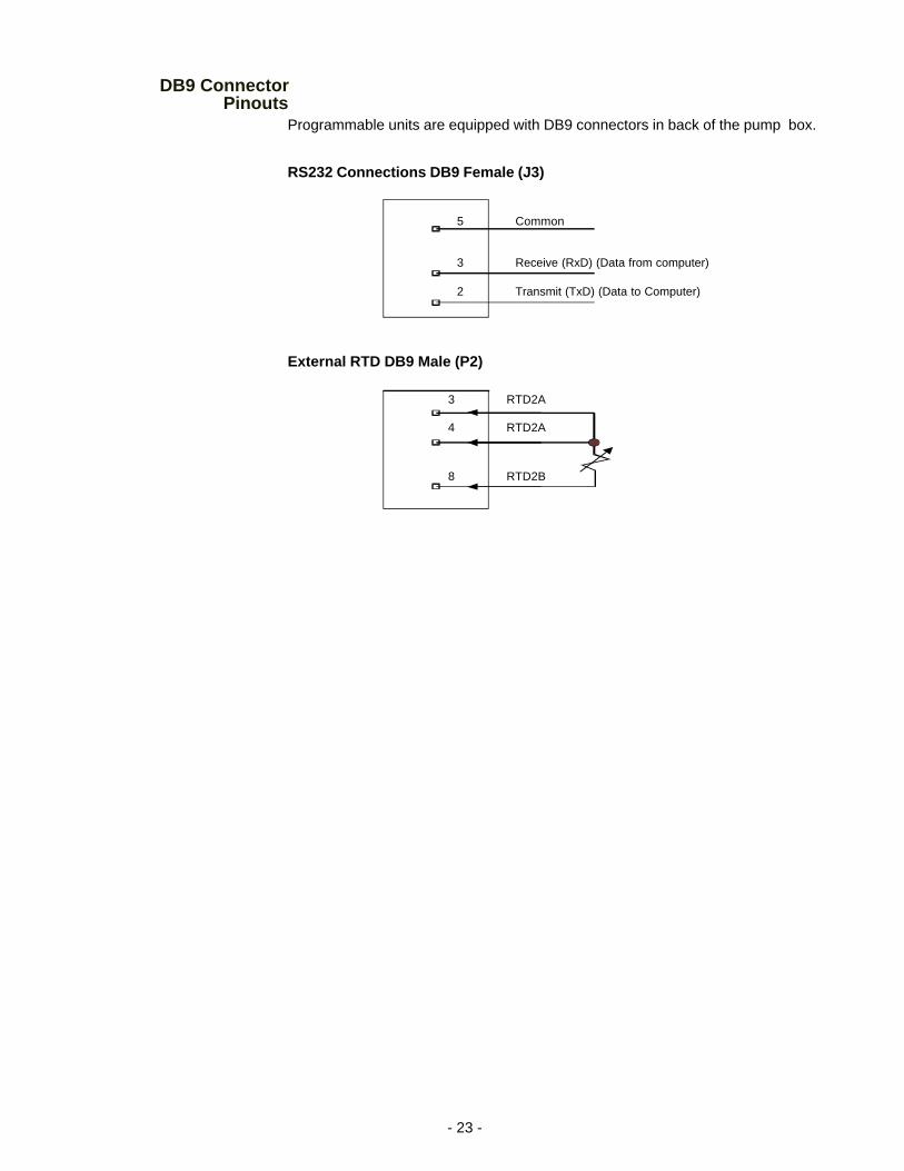
DB9 ConnectorPinouts
Programmable units are equipped with DB9 connectors in back of the pump box.
RS232 Connections DB9 Female (J3)
External RTD DB9 Male (P2)
5 Common
3 Receive (RxD) (Data from computer)
2 Transmit (TxD) (Data to Computer)
3 RTD2A
4 RTD2A
8 RTD2B
- 24 -
Maintenance & Troubleshooting
To avoid electrical shock, disconnect the mains cord prior to removingany access panels or covers.
Cleaning
Turn the unit off before cleaning.
Routine cleaning can be achieved by simply sponging down the seamlessstainless steel tank with a mild soapy solution.
Do not use steel wool; its abrasiveness will lead to rusting.
Dry the circulator using a soft cloth.
For proper operation, the unit needs to pull substantial amounts of airthrough a condenser. A build up of dust or debris on the fins of the condenserwill lead to a loss of cooling capacity.
Periodic vacuuming of the condenser is necessary. The frequency of cleaningdepends on the operating environment. After initial installation we recommendthe wrapper be removed and a monthly visual inspection of the condenser bemade. After several months the frequency of cleaning will be established.
AlgaeTo restrict the growth of algae in the circulator, we recommend the circulatorcover be kept in place and that all circulation lines be opaque. This willeliminate the entrance of light required for the growth of most common algae.
NESLAB recommends the use of Chloramine-T, one gram per gallon.
ChecklistUnit will not startMake sure the voltage of the power source meets the specified voltage,±10%. Refer to the serial number label on the rear of the unit to identify thespecific electrical requirements of your unit.
Check the High Temperature/Low Liquid Level Safety. If the FAULT light is on,make sure the fluid level in the circulator is between the marks in the baffle andthe HIGH TEMP/LOW LEVEL SAFETY setting is greater than the fluid tem-perature. Turn the unit's I/O switch off than back on to reset the safety.
- 25 -
Loss of cooling capacityBe sure the cooling capacity of the unit has not been exceeded if circulatingto an external system.
When the unit is shut off, wait approximately five minutes before restarting.This allows time for the refrigeration pressures to equalize. If the pressuresare not allowed to equalize, the compressor will short-cycle (clicking sound)and no cooling will occur.
Proper ventilation is required for heat removal. Make sure ventilationthrough the front and rear panels is not impeded and the panels are free ofdust and debris.
Ice build up on the cooling coils can act as insulation and lower the coolingcapacity. Raise the temperature of the circulator to de-ice the cooling coil andincrease the concentration of non-freezing fluid.
No external circulationMake sure the stainless steel plugs on the PUMP INLET and PUMPOUTLET have been removed.
Check for obstructions, kinks, or leaks in the circulation tubing.
Circulation will cease when the pump head has been exceeded.
- 26 -
WARRANTY
NESLAB Instruments, Inc. warrants for 12 months from date of shipment any NESLAB unit according to thefollowing terms.
Any part of the unit manufactured or supplied by NESLAB and found in the reasonable judgment of NESLABto be defective in material or workmanship will be repaired at an authorized NESLAB Repair Depot withoutcharge for parts or labor. The unit, including any defective part must be returned to an authorized NESLABRepair Depot within the warranty period. The expense of returning the unit to the authorized NESLAB RepairDepot for warranty service will be paid for by the buyer. NESLAB’s responsibility in respect to warranty claimsis limited to performing the required repairs or replacements, and no claim of breach of warranty shall because for cancellation or recision of the contract of sales of any unit.
With respect to units that qualify for field service repairs, NESLAB’s responsibility is limited to the componentparts necessary for the repair and the labor that is required on site to perform the repair. Any travel labor ormileage charges are the financial responsibility of the buyer.
The buyer shall be responsible for any evaluation or warranty service call (including labor charges) if nodefects are found with the NESLAB product.
This warranty does not cover any unit that has been subject to misuse, neglect, or accident. This warrantydoes not apply to any damage to the unit that is the result of improper installation or maintenance, or to anyunit that has been operated or maintained in any way contrary to the operating or maintenance instructionsspecified in NESLAB’s Instruction and Operation Manual. This warranty does not cover any unit that has beenaltered or modified so as to change its intended use.
In addition, this warranty does not extend to repairs made by the use of parts, accessories, or fluids which areeither incompatible with the unit or adversely affect its operation, performance, or durability.
NESLAB reserves the right to change or improve the design of any unit without assuming any obligation tomodify any unit previously manufactured.
THE FOREGOING EXPRESS WARRANTY IS IN LIEU OF ALL OTHER WARRANTIES, EXPRESSED ORIMPLIED, INCLUDING BUT NOT LIMITED TO WARRANTIES OR MERCHANTABILITY AND FITNESS FORA PARTICULAR PURPOSE.
NESLAB’S OBLIGATION UNDER THIS WARRANTY IS STRICTLY AND EXCLUSIVELY LIMITED TO THEREPAIR OR REPLACEMENT OF DEFECTIVE COMPONENT PARTS AND NESLAB DOES NOT ASSUMEOR AUTHORIZE ANYONE TO ASSUME FOR IT ANY OTHER OBLIGATION.
NESLAB ASSUMES NO RESPONSIBILITY FOR INCIDENTAL, CONSEQUENTIAL, OR OTHER DAMAGESINCLUDING, BUT NOT LIMITED TO LOSS OR DAMAGE TO PROPERTY, LOSS OF PROFITS OR REV-ENUE, LOSS OF THE UNIT, LOSS OF TIME, OR INCONVENIENCE.
This warranty applies to units sold in the United States. Any units sold elsewhere are warranted by the affiliatedmarketing company of NESLAB Instruments, Inc. This warranty and all matters arising pursuant to it shall begoverned by the law of the State of New Hampshire, United States. All legal actions brought in relation heretoshall be filed in the appropriate state or federal courts in New Hampshire, unless waived by NESLAB.