rte series refrigerated bath/circulators digital · pdf filerte series refrigerated...
TRANSCRIPT

RTE Series Refrigerated
Bath/CirculatorsDigital Controller
Instruction and Operation Manual
Thermo NESLAB Manual P/N U00479Rev. 12/12/00
(505)872-0037idealvac.com
idealvac.com

- 1 -
Table of ContentsPREFACE
Compliance ............................................................................................. 2Unpacking ............................................................................................... 2Warranty ................................................................................................. 2NES-care ................................................................................................ 2After-sale Support ................................................................................... 2
SECTION ISafety
Warnings ................................................................................................ 3SECTION II
General InformationDescription .............................................................................................. 4Specifications ......................................................................................... 4
SECTION IIIInstallation
Site ......................................................................................................... 5Electrical Requirements .......................................................................... 5Plumbing Requirements ......................................................................... 6Fluids ...................................................................................................... 8Filling Requirements ............................................................................... 8Water Quality Standards and Recommendations ................................... 9
SECTION IVOperation
Start Up................................................................................................... 10Controller Keypad & Display ................................................................... 10Changing a Value ................................................................................... 11Controller Displays .................................................................................. 11Operator's Loop ...................................................................................... 12Setup Loop ............................................................................................. 13High Temperature/Low Liquid Level Safety ............................................ 159-Pin Accessory Connectors ................................................................... 16Analog Interface (Optional) ..................................................................... 17Autorefill (Optional) ................................................................................. 18Flow Control Valve (Optional) ................................................................. 19Sealable Bath Lid (Optional) ................................................................... 19
SECTION VMaintenance
Service Contracts ................................................................................... 20Reservoir Cleaning ................................................................................. 20Algae....................................................................................................... 20Condenser .............................................................................................. 21Error Messages ....................................................................................... 21Additional Loops ..................................................................................... 22Calibration Loop ...................................................................................... 23Calibration Procedure ............................................................................. 23
SECTION VITroubleshooting
Checklist ................................................................................................. 25Service Assistance and Technical Support ............................................. 26
APPENDIX A THERMO NESLAB SERIAL COMMUNICATION PROTOCOL
APPENDIX B PROGRAMMING SOFTWARE/RS232 COMMUNICATION
WARRANTY

- 2 -
PrefaceCompliance
Products tested and found to be in compliance with the requirements defined in the EMCstandards defined by 89/336/EEC as well as Low Voltage Directive (LVD) 73/23/EEC can beidentified by the CE label on the rear of the unit. The testing has demonstrated compliancewith the following directives:
LVD, 73/23/EEC Complies with UL 3101-1:93
EMC, 89/336/EEC EN 55011, Class A VerificationEN 50082-1:1992IEC 1000-4-2:1995IEC 1000-4-3:1994IEC 1000-4-4:1995
For any additional information refer to the Letter of Compliance that shipped with the unit(Declaration of Conformity).
UnpackingRetain all cartons and packing material until the unit is operated and found to be in goodcondition. If the unit shows external or internal damage, or does not operate properly, contactthe transportation company and file a damage claim. Under ICC regulations, this is yourresponsibility.
WarrantyUnits have a warranty against defective parts and workmanship for one full year from date ofshipment. See back page for more details.
NES-care ExtendedWarranty Contract
• Extend parts and labor coverage for an additional year.
• Worry-free operation.
• Control service costs.
• Eliminate the need to generate repair orders.
• No unexpected repair costs.
Other contract options are available. Please contact Thermo NESLAB formore information.
After-sale SupportThermo NESLAB is committed to customer service both during and after the sale. If youhave questions concerning the operation of your unit or the information in this manual,contact our Sales Department. If your unit fails to operate properly or if you have questionsconcerning spare parts or Service Contracts, contact our Service Department.
Before calling, please refer to the serial number label on the rear of the unit and page 22 toobtain the following information:
- BOM number _________________________
- Serial number _________________________
- Software version (see page 22) ___________

- 3 -
Section I SafetyWarnings
Make sure you read and understand all instructions and safety precautionslisted in this manual before installing or operating your unit. If you have anyquestions concerning the operation of your unit or the information in thismanual, contact our Sales Department.
Performance of installation, operation, or maintenance proceduresPerformance of installation, operation, or maintenance proceduresPerformance of installation, operation, or maintenance proceduresPerformance of installation, operation, or maintenance proceduresPerformance of installation, operation, or maintenance proceduresother than those described in this manual may result in a hazardousother than those described in this manual may result in a hazardousother than those described in this manual may result in a hazardousother than those described in this manual may result in a hazardousother than those described in this manual may result in a hazardoussituation and may void the manufacturer's warranty.situation and may void the manufacturer's warranty.situation and may void the manufacturer's warranty.situation and may void the manufacturer's warranty.situation and may void the manufacturer's warranty.
Transport the unit with care. Sudden jolts or drops can damage theTransport the unit with care. Sudden jolts or drops can damage theTransport the unit with care. Sudden jolts or drops can damage theTransport the unit with care. Sudden jolts or drops can damage theTransport the unit with care. Sudden jolts or drops can damage therefrigeration lines. The units weigh approximately: RTE-111, 86 poundsrefrigeration lines. The units weigh approximately: RTE-111, 86 poundsrefrigeration lines. The units weigh approximately: RTE-111, 86 poundsrefrigeration lines. The units weigh approximately: RTE-111, 86 poundsrefrigeration lines. The units weigh approximately: RTE-111, 86 pounds(390 kilograms); RTE-211, 99 pounds (45 kilograms); RTE-221, 106(390 kilograms); RTE-211, 99 pounds (45 kilograms); RTE-221, 106(390 kilograms); RTE-211, 99 pounds (45 kilograms); RTE-221, 106(390 kilograms); RTE-211, 99 pounds (45 kilograms); RTE-221, 106(390 kilograms); RTE-211, 99 pounds (45 kilograms); RTE-221, 106pounds (48 kilograms). Units should be transported with equipmentpounds (48 kilograms). Units should be transported with equipmentpounds (48 kilograms). Units should be transported with equipmentpounds (48 kilograms). Units should be transported with equipmentpounds (48 kilograms). Units should be transported with equipmentdesigned to lift these weights.designed to lift these weights.designed to lift these weights.designed to lift these weights.designed to lift these weights.
Observe all warning labels.Observe all warning labels.Observe all warning labels.Observe all warning labels.Observe all warning labels.
Never remove warning labels.Never remove warning labels.Never remove warning labels.Never remove warning labels.Never remove warning labels.
Never operate damaged or leaking equipment.Never operate damaged or leaking equipment.Never operate damaged or leaking equipment.Never operate damaged or leaking equipment.Never operate damaged or leaking equipment.
Never operate the unit without bath fluid in the bath.Never operate the unit without bath fluid in the bath.Never operate the unit without bath fluid in the bath.Never operate the unit without bath fluid in the bath.Never operate the unit without bath fluid in the bath.
Never use pure ethylene glycol as a bath fluid. Never use pure ethylene glycol as a bath fluid. Never use pure ethylene glycol as a bath fluid. Never use pure ethylene glycol as a bath fluid. Never use pure ethylene glycol as a bath fluid. Above 80°C the user isresponsible for the fluid used.
For 220 - 240 volt units supplied without a line cord, use a harmonizedFor 220 - 240 volt units supplied without a line cord, use a harmonizedFor 220 - 240 volt units supplied without a line cord, use a harmonizedFor 220 - 240 volt units supplied without a line cord, use a harmonizedFor 220 - 240 volt units supplied without a line cord, use a harmonized(HAR) grounded 3-conductor cord, type (HAR) grounded 3-conductor cord, type (HAR) grounded 3-conductor cord, type (HAR) grounded 3-conductor cord, type (HAR) grounded 3-conductor cord, type H 0 5H 0 5H 0 5H 0 5H 0 5 V VV VV VV VV V - F- F- F- F- F , with conductors, with conductors, with conductors, with conductors, with conductorslisted below. A suitable cord end is required for connecting to thelisted below. A suitable cord end is required for connecting to thelisted below. A suitable cord end is required for connecting to thelisted below. A suitable cord end is required for connecting to thelisted below. A suitable cord end is required for connecting to theequipment (see unit socket) and must terminate with an IEC approvedequipment (see unit socket) and must terminate with an IEC approvedequipment (see unit socket) and must terminate with an IEC approvedequipment (see unit socket) and must terminate with an IEC approvedequipment (see unit socket) and must terminate with an IEC approvedplug for proper connection to power supply.plug for proper connection to power supply.plug for proper connection to power supply.plug for proper connection to power supply.plug for proper connection to power supply.
RTE-111 and RTE-211 Nominal 1.0 mm2 cross section rated 10 AmpsUnit Socket: IEC - 320 C13
RTE-221 Nominal 1.5 mm2 cross section rated 16 AmpsUnit Socket: IEC - 320 C19
Always turn off the unit and disconnect the line cord from the powerAlways turn off the unit and disconnect the line cord from the powerAlways turn off the unit and disconnect the line cord from the powerAlways turn off the unit and disconnect the line cord from the powerAlways turn off the unit and disconnect the line cord from the powersource before performing any service or maintenance procedures, orsource before performing any service or maintenance procedures, orsource before performing any service or maintenance procedures, orsource before performing any service or maintenance procedures, orsource before performing any service or maintenance procedures, orbefore moving the unit.before moving the unit.before moving the unit.before moving the unit.before moving the unit.
Always empty the bath before moving the unit.Always empty the bath before moving the unit.Always empty the bath before moving the unit.Always empty the bath before moving the unit.Always empty the bath before moving the unit.
Never operate equipment with damaged line cords.Never operate equipment with damaged line cords.Never operate equipment with damaged line cords.Never operate equipment with damaged line cords.Never operate equipment with damaged line cords.
Refer service and repRefer service and repRefer service and repRefer service and repRefer service and repairs to a qualified technician.
In addition to the safety warnings listed above, warnings are postedthroughout the manual. These warnings are designated by an exclamationmark inside an equilateral triangle with text highlighted in bold print. Readand follow these important instructions. Failure to observe these instructionscan result in permanent damage to the unit, significant property damage,personal injury or death.

- 4 -
RTE-111 RTE-211 RTE-221
15 lpm at 0' (0 M)0 lpm at 16' (4.9 M)
Section II General InformationDescription
The RTE-Series Refrigerated Bath/Circulators are designed to providetemperature control for applications requiring a fluid work area or pumping toan external system.
Units consist of a non-CFC air-cooled refrigeration system, circulation pump,seamless stainless steel bath, work area cover, and a temperature controller.
SpecificationsTemperature Range1
Temperature Stability2,3,4
Cooling Capacity2,5
WattsBTU/H
Pump Capacity2
Heater (Watts)60 Hz Models50 Hz Models
Refrigerant
Bath Work Area(L x W x D)
InchesCentimeters
Bath VolumeGallons
Liters
Case Dimensions6
Inches (H x W x D)Centimeters (H x W x D)
Power Requirements7
Shipping WeightPounds
Kilograms
8001000
8001000
16001800
115 V, 60 Hz220V, 50 Hz
1. Low-end temperature for 50Hz units is -18°C, -23°C and -21°C respectively.2. Specifications listed for units operating to +5°C using water. Other specifications determined
using fluid with specific heat of 0.6, ambient +20°C (+70°F).3. For operation below 0°C, covering the bath work area may improve stability.4. For some applications, agitation and stability above ambient may be improved by
connecting a small length of hose between the pump connections on the rear of the unit.5. 50 Hz RTE-111 units have a 375 watt cooling capacity.6. Add 1½ inches (3.8 cm) to depth for plumbing fittings.7. Control transformer fusing - 115VAC units = (T=Time Delay) 500mA 250V 5 x 20mm (Qty 1),
220VAC units =[T=Time Delay] 250mA 250V to 5 x 20mm (Qty 2).Bussman fusing part numbers: 500mA fuse = Bussman S504-500mA
250mA fuse = Bussman S504-250mA
-25°C to +150°C -23°C to +150°C
±0.01°C
5001705
R134a
43/4 x 8 x 612.1 x 20.3 x 15.3
91/4 x 10 x 623.5 x 25.4 x 15.2
91/4 x 10 x 923.5 x 25.4 x 22.9
25 x 105/16 x 157/8
63.5 x 26.2 x 40.325 x 123/8 x 183/8
63.5 x 31.4 x 46.7277/8 x 123/8 x 183/8
70.8 x 31.4 x 46.7
8639
9945
10648
1.97.0
3.212.1
5.420.5

- 5 -
Section III InstallationSite
The indentations on the unit's sides are designed to function as handles. Liftthe unit by the handles and locate it on a sturdy work area. Ambient tem-peratures should be inside the range of +50°F to +104°F (+10°C to +40°C).
Never place the unit in a location where excessive heat, moisture, orcorrosive materials are present.
The unit has an air-cooled refrigeration system. Air is drawn through thefront panel and discharged through the rear panel. The unit must bepositioned so the air intake and discharge are not impeded. A minimumclearance of 12 inches (30 centimeters) at the front and rear of the unit isnecessary for adequate ventilation. Inadequate ventilation will reducecooling capacity and, in extreme cases, can cause compressor failure.
Excessively dusty areas should be avoided and a periodic cleaning scheduleshould be instituted (see Section VI, Cleaning).
The unit will retain its full rated capacity in ambient temperatures up toapproximately +75°F (+24°C). Above +75°F, reduce the cooling capacity 1%for every 1°F above +75°F, to a maximum ambient temperature of +104°F.In terms of Celsius, reduce the cooling capacity 1% for every 0.5°C above+24°C, to a maximum ambient temperature of +40°C.
ElectricalRequirements
Line voltage may be easily accessible inside the pump/control box.Always unplug the unit prior to removing pump/control box cover.
Refer to the serial number label on the rear of the unit to identify the specificelectrical requirements of your unit.
Ensure the voltage of the power source meets the specified voltage, ±10%.
The unit construction provides extra protection against the risk of electricshock by grounding appropriate metal parts. The extra protection may notfunction unless the power cord is connected to a properly grounded outlet. Itis the user's responsibility to assure a proper ground connection is provided.
For 220 - 240 volt units supplied without a line cord, use a harmonized(HAR) grounded 3-conductor cord, type H 0 5 V V - F , with conductorslisted below. A suitable cord end is required for connecting to theequipment (see unit socket) and must terminate with an IEC approvedplug for proper connection to power supply.
RTE-221 Nominal 1.5 mm2 cross section rated 16 AmpsUnit Socket: IEC - 320 C19
RTE-111 and RTE-211 Nominal 1.0 mm2 cross section rated 10 AmpsUnit Socket: IEC - 320 C13

- 6 -
PlumbingRequirements
Ensure the unit is off before connecting tubing to the unit.
To prevent damage to the plumbing lines, always support the ¾"fittings while installing/removing the pumping caps and lines.
Hose ConnectionsThe pump connections are located at the rear of the pump box and arelabelled PUMP INLET and PUMP OUTLET. These connections are bentupward so the recirculating fluid will drain back into the reservoir when thehoses are disconnected. Both connections are capped with stainless steelserrated plugs.
The pump lines have ¼" MPT for mating with standard plumbing fittings. Foryour convenience stainless steel adapters, ¼" FPT to 3/8" O.D. serratedfitting, are provided. (To assure proper fit, they should be installed using 1½turns of Teflon® tape around the threads.)
Flexible tubing, if used, should be of heavy wall or reinforced construction.Make sure all tubing connections are securely clamped. Avoid runningtubing near radiators, hot water pipes, etc. If substantial lengths of tubingare necessary, insulation may be required to prevent loss of cooling capac-ity. Tubing and insulation are available from Thermo NESLAB. Contact ourSales Department for more information (see Preface, After-sale Support).
It is important to keep the distance between the unit and the external systemas short as possible, and to use the largest diameter tubing practical. Tubingshould be straight and without bends. If diameter reductions must be made,make them at the inlet and outlet of the external system, not at the unit.
If substantial lengths of cooling lines are required, they should be pre-filledwith bath fluid before connecting them to the unit. This will ensure that anadequate amount of fluid will be in the bath once it is in operation.
PumpingThe pump is designed to deliver a flow of 15 liters per minute (4 gallons perminute) at 0 feet head. To prevent external circulation, the PUMP INLETand PUMP OUTLET lines on the rear of the unit are capped. The caps mustbe removed when external circulation is required.
To properly secure external hose connections to the unit, wrap Teflon® tapearound the pipe line threads before installation. Once the hose connectionsare made, the hoses must be properly plumbed to an external system. It isimportant the bath is not in operation until all plumbing is complete.
NOTE: To increase agitation in the bath when not circulating externally,connect a short loop of hose between the inlet and outlet lines.
If the bath is not used for external circulation or increased agitation, makesure the stainless steel caps are in place prior to operating the bath.

- 7 -
Circulating to an open container
A stainless steel leveling device is available to aid circulation to an openvessel. Contact our Sales Department for more information (see Preface).
Support the leveling device over the open container with a ringstand.Stagger the tubes in the leveling device so one tube is submerged in thevessel fluid, and the other tube is level with the fluid surface. Connect thedeeper tube to the PUMP OUTLET and the shorter tube to the PUMPINLET.
Adjust the flow rate using the accessory flow control valve connected to thePUMP OUTLET, or by partially restricting the outlet tubing. When properlyadjusted, the pump inlet will draw an occasional air bubble to prevent overflow, and the pump outlet will force fluid through the submerged tube toprevent aeration of the vessel.
To avoid siphoning the bath work area when the unit is shut off, lift theleveling device out of the vessel and above the level of the unit.
Circulating through two closed-loops
The pump can be used to circulate through two closed-loop systems.Connect the shortest practical length of flexible tubing from the PUMPOUTLET to the inlet of external system #1. Connect the outlet of system #1directly into the bath work area. Connect tubing from the bath work area tothe inlet of system #2. Connect the outlet of system #2 to the PUMP INLET.
System #1
System #2
BathWork Area
Pump Box
Bath (Top View)
Bath (Rear View) Open Container
Outlet Inlet
LevellingDevice

- 8 -
Drain
Ensure the temperature of the bath fluid is safe before draining the unit.
The unit is equipped with a drain located at the back of the unit at the baseof the bath. The drain has ¼" MPT and is capped with a stainless steel plug.To drain the reservoir simply remove the cap.
To assure proper fit when replacing the cap, be sure to line the threads with1½ turns of Teflon® tape.
Fluids
Never use flammable or corrosive fluids with this unit.
The selected fluid must have a viscosity of 50 centistokes or less at thelowest operating temperature.
Filtered tap water is the recommended fluid for operation from +8°C to+80°C. See Water Quality Standards and Recommendation on the nextpage.
For operation from -30°C to +8°C, a 50/50 mixture, by volume, of tap waterand laboratory grade ethylene glycol is suggested.
Never use pure ethylene glycol as a bath fluid. Above 80°C and below-30°C, the user is responsible for the fluid used.
FillingRequirements
The bath work area has a high and low level marker to guide filling. Themarkers are 1 inch horizontal slits located in the center of the stainless steelbaffle separating the work area and the pump assembly. The correct fluidlevel falls between these two markers. The heating and cooling coils will beexposed and may become damaged if the correct fluid level is not provided.
When pumping to an external system, keep extra fluid on hand to maintainthe proper level in both the circulating lines and the external system.
Never run the unit when the work area is empty. Avoid overfilling.Overfilling the bath may damage the insulation and affects stability aswell as low-end performance.

- 9 -
Unfavorably high total ionized solids (TIS) can accelerate the rate of gal-vanic corrosion. These contaminants can function as electrolytes whichincrease the potential for galvanic cell corrosion and lead to localizedcorrosion such as pitting which can be observed at the studs and on theoutside surface of cooling coils. Eventually, the pitting will become soextensive that the coil will leak refrigerant into the water reservoir.
For example, raw water in the U.S. averages 171 ppm (of NaCl). Therecommended level for use in a water system is between 0.5 to 5.0 ppm (ofNaCl).
Recommendation: Initially fill the tank with distilled/deionized water. Do notuse untreated tap water, as the total ionized solids level may be too high.
Maintain this water quality at a resistivity of between 1 to 10 megohm-cm(compensated to 25°C) by using a purification system. Although the initial fillmay be as high as 10 megohm-cm (compensated to 25°C), the desired levelfor long time usage is 1 to 3 megohm-cm (compensated to 25°C).
The above two recommendations will reduce the electrolytic potential of thewater and prevent or reduce the galvanic corrosion observed.
Water Quality Standardsand Recommendations
Permissible (PPM) Desirable (PPM)Microbiologicals(algae, bacteria, fungi) 0 0Inorganic ChemicalsCalcium <40 0.6Chloride 250 <25Copper 1.3 1.0Iron 0.3 <0.1Lead 0.015 0Magnesium <12 0.1Manganese 0.05 <0.03Nitrates\Nitrites 10 as N 0Potassium <20 0.3Silicate 25 <1.0Sodium <20 0.3Sulfate 250 <50Hardness 17 <0.05Total Dissolved Solids 50 10Other ParameterspH 6.5-8.5 7-8Resistivity 0.01* 0.05-0.1** Megohm-Cm (Compensated to 25°C)
15.00
10.00
3.00
1.00
0.100.05
Res
istiv
ity (m
egoh
m-c
m @
25°
C)
Not Recommended, Increasingly Corrosive
Operations with Stainless Steel Systems
Operations withMixed MetalsCopper/Brass/Stainless Steel CONSULT MATERIALS ENGINEER
Water Quality Considerations
°C10 20 30 40 50 60 70 80

- 10 -
Section IV OperationStart Up
Before starting the unit, check all electrical and plumbing connections andmake sure the work area has been properly filled with bath fluid.
To start the bath, place the I/O circuit breaker on the side of the control boxto the I (power on) position. The pump will start and the controller will displaythe temperature of the fluid in the reservoir.
The digital controller controls temperature using a PID (Proportional-Integral-Derivative) algorithm. It is designed with self-diagnostic features and easy touse operator interface.
Controller Keypad& Display
The controller's HEAT and COOL indicators show the status of the refrigera-tion system and heater. The HEAT indicator is lit when the heater is on. TheHEAT indicator flashes when the heater is pulsating. The COOL indicator islit when the refrigeration system is removing heat from the cooling fluid. Abalance between COOL and HEAT controls the temperature.
NOTE: Below 50°C the refrigeration system is on unless the setpoint is morethan 2°C above the bath temperature. This allows for rapid heat up. Above50°C the refrigeration system is off unless the setpoint is more than 2°Cbelow the bath temperature. This allows for rapid cool down.
The REMOTE indicator illuminates whenever the unit is configured to accepta remote setpoint. The controller's SENSOR indicator illuminates wheneverthe optional external sensor is selected. See Controller Displays on the nextpage for information on the °C display.
NEXT ENTERUse this key to scroll forward through the menus and also to accept andsave changes.

- 11 -
YES,This dual purpose key is used to answer Yes to Y/N questions or to incre-ment numerical values upward for setting numeric values.
NO,This dual purpose key is used to answer No to Y/N questions or to decre-ment numerical values downward for setting numeric values.
Changing a ValueThe YES key increments the value. The NO key decrements the value.
The display will flash as soon as either key is depressed, and will continue toflash until the NEXT ENTER key is pressed twice to accept the new value.
The new value will not be used by the controller until the NEXT ENTER keyis depressed twice and the display stops flashing.
NOTE: If the ENTER key is not depressed twice within 10 seconds, thecontroller will time out and the new value will not be accepted. The controllerwill revert to the previous setpoint value.
The controller will not allow you to enter a value above the maximum orbelow the minimum (normally +150°C and -25°C).
Controller DisplaysAn alphanumeric display presents numeric readings of various operatingconditions within the bath. Display function is selected by pressing theappropriate keys to move through a menu of available information.
When the controller is first powered up it performs a quick self-test thenenters the Operator's Loop. The Operator's Loop displays the bath tempera-ture and is used to change the setpoint, see page 12. The Setup Loop can beaccessed from the Operator's Loop by pressing and holding the key combina-tions shown on Figure 1 on the next page. The Setup Loop is used to adjustthe controller's PID parameters, select either the internal or optional externalsensor, and set the high/low temperature limits. It is also used to select RS232parameters and display the unit's identification number. See pages 13-14.

- 12 -
Figure 1 Operator's Loop
XXX.X = Reservoir Fluid TemperatureSP = Setpoint
Operator's LoopWhen the controller is first powered up it enters the Operator's Loop, display-ing reservoir fluid temperature. Press the NEXT ENTER key to view thesetpoint.
SP displays the controller setpoint. The display will flash between SP andthe actual setpoint number. Use the YES/NO keys to change the setpointvalue. Once the desired setpoint is displayed, press the NEXT ENTER keytwice.
NOTE: If the bath is controlled via RS232 communications, the setpoint cannot be changed from the keypad.

- 13 -
Figure 2 Setup Loop (1 of 2)
Setup LoopThe Setup Loop is used to adjust the controller's PID parameters; select eitherthe internal (1) or optional external (2) sensor; set the high/low temperaturelimits; adjust RS232 parameters; and display/alter the unit's ID number.
Enter the Setup Loop from the Operator's Loop by pressing and holding theNO key, then press the NEXT ENTER key. Use the YES/NO keys to adjustthe values. Press the NEXT ENTER key twice to accept the new value.Press the NEXT ENTER key only once if the value did not change.
While in the Setup Loop, if a key is not pressed during a one-minute timespan, the controller will automatically return to the Operator's Loop.
NOTE: If the unit exceeds either temperature limit, the appropriate errormessage will flash, see page 21. The unit will not shut down (unless thetemperature also exceeds the high temperature safety setting, see page15).You will also receive an error code if the optional external sensor isselected but it is not installed.
tUnE = TuneHEAt = Heat PID Parameters
Pro = Proportional Band (factory value 1.3%)Int = Integral (factory value 0.75 repeats per minute)dEr = Derivative (factory value 0.05 minutes)
rtd = Sensor1 = Internal2 = External
SP = Setpoint source (optional display see page 17)Hit = High Temperature Limit
Optional. Selecting Analog Input(AnA) as the mode of temperaturecontrol overrides both manualinput from the keypad, and anyserial communication input.

- 14 -
Figure 2 Setup Loop (2 of 2)
Hit = High Temperature LimitLot = Low Temperature Limitr232 = RS232 Protocol
bAUd = BAUD rate (default 9600)dAtA = Data Bits (default 8)StoP = Stop Bit (default 1)PAr = Parity (default NONE)
U id = Unit Identification Number (used for serial communication)
Stor = Store
NOTE: To save all changes, when the display reads Stor press YES. Shouldyou desire to return to the temperature display and abort all changes, whenthe display reads Stor press NO.

- 15 -
High Temperature/Low Liquid Level Safety
High Temperature/Low Liquid
Level SafetyTo protect your application, the adjustable High Temperature/Low LiquidLevel Safety (HIGH TEMP/LOW LEVEL) ensures the heater will not exceedtemperatures that can cause serious damage to your unit. A single tempera-ture sensor, located on the heater coils in the bath, monitors both conditions.A High Temperature/Low Liquid Level fault occurs when the temperature ofthe sensor exceeds the set temperature limit. The safety switch has atemperature range of 7°C to 180°C.
In the event of a fault, the red LED near the adjustment dial will light, thedisplay will go blank, and the unit will shut down. The cause of the fault mustbe identified and corrected before the unit can be restarted.
The safety is not preset and must be adjusted during initial installation.
To set the safety, locate the HIGH TEMP/LOW LEVEL SAFETY adjustmentdial on the right side of the pump box. Turn the dial fully clockwise and turnthe I/O switch off then back on.
Start the unit. Adjust the setpoint for a few degrees higher than the highestdesired fluid temperature and allow the bath to stabilize at the temperaturesetpoint. Turn the HIGH TEMP/LOW LEVEL SAFETY dial counterclockwiseuntil you hear a click and the unit shuts down. The red LED near the adjust-ment dial will light to indicate a fault has occurred.
Cool the bath and then, without moving the adjustment dial, turn the I/Oswitch off then back on.
NOTE: Thermo NESLAB recommends rechecking operation if the unit ismoved.

- 16 -
9-Pin AccessoryConnector
COMM Pin Connections
Pin # Function1 No connection.2 TX = Transmitted data from controller3 RX = Received data to controller4 No connection5 GND = Signal ground6 No connection.7 No connection8 No connection9 No connection
Hardware Internal Connector Mating ConnectorAMP Part# 745491-2 AMP Part# 745492-2
Remote Sensor Connections
Pin # Function1 3-wire RTD connection A2 No connection3 No connection4 3-wire RTD connection A5 No connection6 No connection.7 3-wire RTD connection B8 No connection9 No connection
Hardware Internal Connector Mating ConnectorAMP Part# 745492-2 AMP Part# 745491-2
COMM
The unit is equipped with two 9-pin D-connectors located on the rear of thecontrol box. The female COMM is used for RS232 communication (seeAppendix A); the male is used with an optional external sensor.
SENSOR
RTD
Example

- 17 -
Analog Interface(Optional)
An optional 15-pin D subminiature female receptacle for analog interface islocated on the rear of the control/pump box.
ACCESSORYPin # Function
1 Chassis ground.
2 No connection.
3 - 5 No connection.
6 Analog Ground. The analog ground is physically separated from the power ground throughout theunit. To prevent offsets that result from ground currents, the analog and power grounds are onlyconnected at the unit's power supply. Analog ground should only be used as a reference pin.
7 Temperature Out. The fluid temperature, as measured by the sensor slected in theSetup Loop (see page13) , can be read at this pin. The temperature scale is 10mV/°C, referenced to analog ground,pin 6 (example: +150mV = +15.0°C).
8 No connection.
9 Power Ground (5V RTN).
10 - 13 No connection.
14 +5V. Power supply of +5VDC (15mA maximum).
15 Setpoint In. The temperature setpoint can be controlled by applying a known voltage to this pin. Thetemperature scale is 10mV/°C, referenced to analog ground, pin 6 (example: +230mV = +23.0°C).Note: The setpoint is updated only when the voltage represents a temperature within the setpoint limits.
The analog setpoint signal (Setpoint In) is enabled using the unit's software. Using theSetup Loop discussed on page 13, keep depressing the NEXT ENTER key until SP isdisplayed. Use the YES or NO key to display the desired mode, AnA for analog or LoCfor local, then press NEXT ENTER to continue with the loop. NOTE: The last valueentered is maintained when SP is changed from AnA to LOC or LOC to AnA until a validvoltage is applied.
Store the change.
NOTE: Selecting Analog Input (AnA) as the mode of temperature control overrides bothmanual input from the keypad, and any serial communication input.
The Analog In and Analog Outdiscussed in the Calibration Loopon pages 23 and 24 is applicableto this unit. Analog In calibrationis done by applying a 2Vdcsignal for AiH, and a 0Vdc signalfor AiL. Reference the appropri-ate pins on the ACCESSORYconnector.
Analog Out calibration is done bymeasuring the appropriate pinson the ACCESSORY connector.Adjust the AoH to 1.000Vdcusing the YES and NO keys thenpress ENTER twice. Adjust theAoL to 0.000Vdc using the YESand NO keys then press ENTERtwice.

- 18 -
Autorefill (Optional)The autorefill device is designed to maintain the correct level of fluid in thereservoir. The device consists of a float switch and a solenoid valve. If thefluid level falls, the float switch opens the solenoid valve allowing makeupfluid to fill the reservoir. Once the fluid reaches the proper level, the floatswitch rises and the solenoid valve closes.
The plumbing connection for the autorefill device, labeled WATER INLET, islocated on the rear of the autorefill assembly. The connection is 3/8" ODstainless steel. To prevent damage to your hosing and to prevent the hosefrom slipping of the connection, install the supplied hose barb into yourtubing. Tubing is also available from Thermo NESLAB. Contact our SalesDepartment.
Remove the nut on the WATER INLET connection and install the tubingfrom your makeup fluid source. Reinstall the nut and tubing on the connec-tion. Install the device on the unit. To secure the device to the unit, tightenthe screw located between the float switch and the makeup fluid outlet line.If desired, place the supplied cover on the unit.
The autorefill device requires its own source of electrical power. A connectorfor the supplied line cord is also located on the rear of the autorefill device.The connector is labelled POWER.
Float Switch
WATER INLETPOWER
Makeup FluidOutlet Line

- 19 -
Sealable Bath Lid(Optional)
Depending on your applicationrequirements and/or working envi-ronment, a bath lid is available tomake RTE-111 reservoirs sealable(not pressurized).
The top of the pump grate in theunit's reservoir has four holes cutinto the sheet metal. Align theprotrusions on the lid with theseholes as shown. A locking adjustablegrip latch tightens the lid to the tank top allowingan EDPM gasket to create a seal.
The lid also has a nitrogen purge port. The purge port is a ¼" male Swagelocconnector with an o-ring seal.
Bath Connections External Hose Connections
Direction of Flow
Finger Tight Finger Tight +1¼ Turn
Spare Part
C LO SE
OPEN
Flow ControlValve (Optional)
An optional flow control valve is available to control external circulation. Thevalve assembly consists of the nine pieces shown below. Once assembledand installed on the unit, clamp a hose to the end of the assembly. Turn theunit on and check for leaks with the valve opened as well as closed.
LatchNitrogen Purge
Holes

- 20 -
Refrigeration Cable
Cable Strap
Section V MaintenanceTo avoid electrical shock, disconnect the mains cord prior to remov-ing any access panels or covers.
Service ContractsThermo NESLAB offers on-site Service Contracts designed to provideextended life and minimal down-time for your unit. For more information,contact our Service Department (see Preface, After-sale Support).
Reservoir CleaningRoutine cleaning can be achieved by simply sponging down the seamlessstainless steel tank with tap water. (Dish washing detergent may be usedbut the tank must be thoroughly rinsed.)
To gain access to the entire reservoir the pump box and reservoir covershould be removed.
Remove the line cord from the rear of the unit and then remove the fourscrews (two on each side) securing the reservoir's cover.
To get slack on the refrigeration cable, remove the cable strap. The cableitself does not need to be disconnected.
Turn the cover assembly over and carefully place it on a supporting plat-form.
AlgaeTo restrict the growth of algae in the bath, we recommend the bath cover bekept in place and that all circulation lines be opaque. This will eliminate theentrance of light required for the growth of most common algae.
Thermo NESLAB recommends the use of Chloramine-T, 1 gram per 3½liters.
- 21 -
CondenserFor proper operation, the unit needs to pull substantial amounts of airthrough a condenser. A build up of dust or debris on the fins of thecondenser will lead to a loss of cooling capacity.
Periodic vacuuming of the condenser is necessary. To access the condenserthe front grille must be removed.
The unit must be turned off before the front panel is removed.
RTE-111 units have a one-piece grille assembly. Pull forward to remove.
RTE-211 and RTE-221 units have a two piece grille assembly. First removethe left (blue-colored) section by simply pulling it forward. Pull forward on theremaining (white-colored) section to remove it.
The frequency of cleaning depends on the operating environment. Afterinitial installation, we recommend a monthly visual inspection of the con-denser. After several months, the frequency of cleaning will be established.
Error MessagesError Action
Er00: ROM ChecksumEr01: RAM Test FailedEr02: Keypad Test FailedEr04-13: Interrupt ErrorEr14: Synchronous ErrorEr15: Asychronous ErrorEr16: Bad CalibrationLoT: Low Temp LimitHiT: High Temp LimitEr23: RTD2 ShortedEr24: RTD2 Open/Not InstalledEr25: RTD1 ShortedEr26: RTD1 OpenHTC: High Temperature CutoutPrES: Pressure Cutout
NOTE: HTC and PrES are optional displays available only on speciallymodified units. Errors 00 through 15 will lockup the controller keypad. Errors00 through 03 may be cleared by depressing the NEXT ENTER key.

- 22 -
Figure 3 Additional Loops
Additional Loops
1, 2, ... = A, B, ...

- 23 -
Calibration LoopThe Calibration Loop is used to calibrate the RTD high and low temperature.The controller's internal temperature sensor is factory calibrated. Werecommend calibrating any external sensor.
Enter the Calibration Loop from the Operator's Loop by pressing and holdingthe NO key while pressing the YES key three times.
CalibrationProcedure
Install a calibrated reference thermometer in the bath. (For external mode,also install the sensor in the bath.) Place the cover on the unit.
The procedure uses the Operator's, Setup and Calibration Loops. In theSetup Loop place the unit in either the internal or external RTD mode ofoperation (RTD1 = Internal , RTD2 = External). Return to the Operator'sLoop and adjust the setpoint to an appropriate high-end temperature.
NOTE: When calibrating the external sensor ensure the controller'sSENSOR indicator is illuminated.
Once the bath reaches the setpoint and stabilizes, go to the CalibrationLoop and, as illustrated on the next page, enter the actual reference ther-mometer reading at either the r1H or r2H prompt.
Store the change and return to the Operator's Loop. Adjust the setpoint toan appropriate low-end temperature. Once the bath reaches the setpointand stabilizes, return to the Calibration Loop and enter the reference ther-mometer reading at either the r1L or r2L prompt. Store the change.
Do not pick points that are outside the safe operating limits of thefluid in your application. For example with a water bath, 90°C and 5°Cwould be typical calibration points.

- 24 -
Figure 4 Calibration Loop
NOTE: To save all changes, when the display reads Stor press YES. Shouldyou desire to return to the temperature display and abort all changes, whenthe display reads Stor press NO.
rtdn n= 1 = Internal sensor, n = 2 = external sensorrnH = High temperaturernL = Low temperatureAin = Only applicable to units with analog interfaceAout = Only applicable to units with analog interfaceStor = Store

- 25 -
Section VI TroubleshootingChecklist
Unit will not startMake sure the voltage of the power source meets the specified voltage,±10%. Refer to the serial number label on the rear of the unit to identify thespecific electrical requirements of your unit.
Check the High Temperature/Low Liquid Level Safety. If the red LED on theside of the controller is on, make sure the fluid level in the bath is betweenthe marks in the baffle and the HIGH TEMP/LOW LEVEL SAFETY setting isgreater than the fluid temperature. Turn the I/O switch off then back on, andattempt to restart.
Loss of cooling capacityBe sure the cooling capacity of the unit has not been exceeded if circulatingto an external system.
When the unit is shut off, wait approximately five minutes before restarting.This allows time for the refrigeration pressures to equalize. If the pressuresare not allowed to equalize, the compressor will short-cycle (clicking sound)and no cooling will occur.
Proper ventilation is required for heat removal. Make sure ventilationthrough the front and rear panels is not impeded and the panels are free ofdust and debris.
Ice build up on the cooling coils can act as insulation and lower the coolingcapacity. Raise the temperature of the bath to de-ice the cooling coil andincrease the concentration of non-freezing fluid.
No external circulationCheck for obstructions, kinks, or leaks in the circulation tubing.
Circulation will cease when the pump head has been exceeded.
No/poor temperature controlCheck RS232/remote operation on or off.
Selecting the optional Analog Input (AnA) as the mode of temperaturecontrol overrides both manual input from the keypad, and any serialcommunication input.
Check external sensor connection. Perform calibration.
Continued on next page.

- 26 -
No serial communicationsAll units are tested for serial communications before they leave the factory.Ensure the REMOTE indicator on the controller is illuminated.
Check all communications commands, they must be exact. See Appendix A.
Check communications settings. The protocol uses an RS-232 serial inter-face with the parameters: 9600 baud, 8 data bits, 1 stop bit and no parity.
Check all wiring for proper connections or possible shorts.
Software to verify serial communication is available from Thermo NESLAB.
Service Assistance and Technical Support
If, after following these troubleshooting steps, your unit fails to operateproperly, contact our Customer Service Department for assistance (seePreface, After-sale Support). In addition to arranging warranty service, ourService Department can provide you with a wiring diagram and a completelist of spare parts for your unit. Before calling, please obtain the following:Part numberSerial numberSoftware Version

- 27 -
Appendix A Serial Communications ProtocolNOTE: This appendix assumes you have a basic understanding of commu-nications protocols.
All data is sent and received in binary form, do not use ASCII. In the follow-ing pages the binary data is represented in hexadecimal (hex) format.
The Neslab Serial Communications Protocol, NC, is based on a master-slave model. The master is a host computer, while the slave is the bath'scontroller. Only the master can initiate a communications transaction (half-duplex). The slave ends the transaction by responding to the master’s query.The protocol uses an RS-232 serial interface with the default parameters:9600 baud, 1 start bit, 8 data bits, 1 stop bit and no parity.
NOTE: Before the unit will communicate, RS232 must be turned on in thecontroller's Setup Loop.
The unit can be controlled through your computer’s serial port by using theunit's standard 9-pin RS-232 connection. Data read of the serial port con-nects to the data transmit (pin 2) of the bath. Data transmit of the serial portconnects to data read (pin 3) of the bath.
Communication cables are available from Thermo NESLAB. Contact oursales department for additional information.
All commands must be entered in the exact format shown in the tables onthe following pages. The tables on on the last page of this Appendix show allcommands available, their format and responses. Controller responses areeither the requested data or an error message. The controller response mustbe received before the host sends the next command.
The host sends a command embedded in a single communications packet,then waits for the controller’s response. If the command is not understood orthe checksums do not agree, the controller responds with an error command.Otherwise, the controller responds with the requested data. If the controllerfails to respond within 1 second, the host should resend the command.

- 28 -
NC Serial Communications ProtocolNOTE: All byte values are shown in hex, hex represents the binary values that must be sent to the bath. Donot use ASCII.
The framing of the communications packet in both directions is:
Checksum region
Lead char Addr-MSB Addr-LSB Command n d-bytes d-byte 1 ... d-byte n Checksum CA 00 01
Lead char CA (hex).
Device address is 1Addr-msb Most significant byte of device address is 00 hex.Addr-lsb Least significant byte of device address is 01 hex.
Command Command byte (see Table 1).
n d-bytes Number of data bytes to follow (00 to 03 hex).d-byte 1 1st data byte (the qualifier byte is considered a data byte).... ...d-byte n nth data byte.Checksum Bitwise inversion of the 1 byte sum of bytes beginning with the most signifi-
cant address byte and ending with the byte preceding the checksum. (Toperform a bitwise inversion, "exclusive OR" the one byte sum with FF hex.)
The master requests information by sending one of the Read Functions as shown in Table 1 on page 30.Since no data is sent to the bath during a read request, the master uses 00 for the number of data bytesfollowing the command byte.
The bath will respond to a Read Function by echoing the lead character, address, and command byte,followed by the requested data and checksum. When the bath sends data, a qualifier byte is sent first,followed by a two byte signed integer (16 bit, MSB sent first). The qualifier byte indicates the precision andunits of measure for the requested data as detailed in Table 2, see page 30.
As an example, the master requests to read internal temperature by sending:
If the temperature is -10.5°C, the slave would reply:
CA 00 01 20 03 11 FF 97 34command byte
3 bytes to follow The checksum is the bitwise inversion ofC8 (00+01+20+03+11+FF+97)
The qualifier byte of 11 indicates a precision of 1
decimal point and units of °C. The temperature of
-10.5°C is -105 decimal = FF97 hex.
CA 00 01 20 00 DEcommand byte
0 bytes of data
The checksum is the bitwiseinversion of 21 (00+01+20+00)
byte values are in hex

- 29 -
The master sets parameters in the bath by sending one of the Set Functions as shown in Table 1. Themaster does not send a qualifier byte in the data field. The master should be preprogrammed to send thecorrect precision and units (it could also read the parameter of interest first to decode the correct precisionand units needed).
For example, if the master wants to set the setpoint to 30°C, it would send :
The slave responds:
command byte
2 bytes to follow
The checksum is the bitwise inversion of 20(00+01+F0+02+01+2C)
The temperature of 30.0°C is 300 decimal = 012C hex.
CA 00 01 F0 02 01 2C DF
CA 00 01 F0 03 11 01 2C CDcommand byte
3 bytes to followThe checksum is the bitwise inversion of32(00+01+F0+03+11+01+2C)
The qualifier byte of 11 indicates a precision of 1
decimal point and units of °C. The temperature of
30.0°C is 300 decimal = 012C hex.

Table 1 (All bytes are in hex)
FUNCTION MASTER SENDS BATH RESPONDS
READRead Internal Temperature CA 00 01 20 00 DE CA 00 01 20 03 qb d1 d2 csRead External Sensor CA 00 01 21 00 DD CA 00 01 21 03 qb d1 d2 csRead Setpoint (control point) CA 00 01 70 00 8E CA 00 01 70 03 qb d1 d2 csRead Low Temperature Limit CA 00 01 40 00 BE CA 00 01 40 03 qb d1 d2 csRead High Temperature Limit CA 00 01 60 00 9E CA 00 01 60 03 qb d1 d2 csRead Proportional Band (P) CA 00 01 71 00 8D CA 00 01 71 03 qb d1 d2 csRead Integral (I) CA 00 01 72 00 8C CA 00 01 72 03 qb d1 d2 csRead Derivative (D) CA 00 01 73 00 8B CA 00 01 73 03 qb d1 d2 cs
SETSet Setpoint (control point)* CA 00 01 F0 02 d1 d2 cs CA 00 01 F0 03 qb d1 d2 csSet Low Temperature Limit* CA 00 01 C0 02 d1 d2 cs CA 00 01 C0 03 qb d1 d2 csSet High Temperature Limit* CA 00 01 E0 02 d1 d2 cs CA 00 01 E0 03 qb d1 d2 csSet Proportional Band CA 00 01 F1 02 d1 d2 cs CA 00 01 F1 03 qb d1 d2 cs(P=1-99.9)Set Integral (I = 0-9.99) CA 00 01 F2 02 d1 d2 cs CA 00 01 F2 03 qb d1 d2 csSet Derivative (D= 0-5.0) CA 00 01 F3 02 d1 d2 cs CA 00 01 F3 03 qb d1 d2 cs
BATH ERROR RESPONSESBad Command N/A CA 00 01 0F 02 01 ed csBad Checksum N/A CA 00 01 0F 02 03 ed cs
MISCELLANEOUSRequest Acknowledge CA 00 01 00 00 FE CA 00 01 00 02 v1 v2 cs
command bytes shown in boldqb = qualifier byted1,d2 = 16 bit signed integer of the value being sent or receivedcs = the checksum of the string (see text)ed = echo back of the command byte as receivedv1,v2 = protocol version* = limited to the range of the bath
Table 2
QUALIFIER BYTE10 hex 0.1 precision, no units of measure20 hex 0.01 precision, no units of measure11 hex 0.1 precision, °C units
Example: The temperature of 45.6 °C would be represented by the qualifier 11 hex, followed by the 2 bytes01 C8 hex (456 decimal).
Appendix B Programming SoftwareNEScom Software/
RS232 Communication
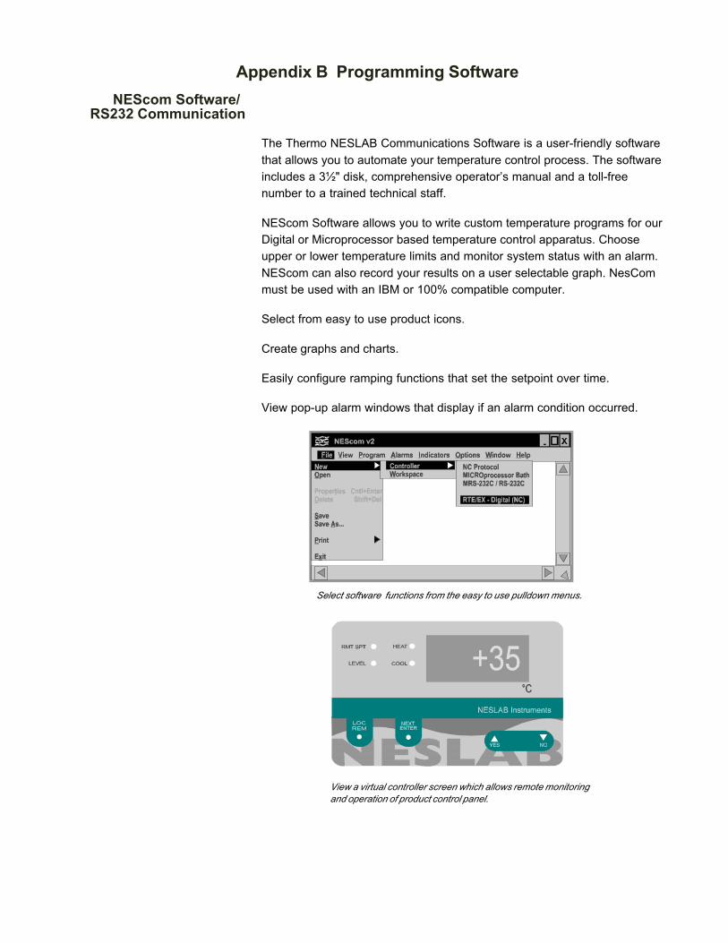
The Thermo NESLAB Communications Software is a user-friendly softwarethat allows you to automate your temperature control process. The softwareincludes a 3½" disk, comprehensive operator’s manual and a toll-freenumber to a trained technical staff.
NEScom Software allows you to write custom temperature programs for ourDigital or Microprocessor based temperature control apparatus. Chooseupper or lower temperature limits and monitor system status with an alarm.NEScom can also record your results on a user selectable graph. NesCommust be used with an IBM or 100% compatible computer.
Select from easy to use product icons.
Create graphs and charts.
Easily configure ramping functions that set the setpoint over time.
View pop-up alarm windows that display if an alarm condition occurred.
Select software functions from the easy to use pulldown menus.
View a virtual controller screen which allows remote monitoringand operation of product control panel.

WARRANTY
Thermo NESLAB Instruments, Inc. warrants for 12 months from date of shipment any Thermo NESLAB unitaccording to the following terms.
Any part of the unit manufactured or supplied by Thermo NESLAB and found in the reasonable judgment ofThermo NESLAB to be defective in material or workmanship will be repaired at an authorized ThermoNESLAB Repair Depot without charge for parts or labor. The unit, including any defective part must bereturned to an authorized Thermo NESLAB Repair Depot within the warranty period. The expense of return-ing the unit to the authorized Thermo NESLAB Repair Depot for warranty service will be paid for by thebuyer. Thermo NESLAB’s responsibility in respect to warranty claims is limited to performing the requiredrepairs or replacements, and no claim of breach of warranty shall be cause for cancellation or recision of thecontract of sales of any unit.With respect to units that qualify for field service repairs, Thermo NESLAB’sresponsibility is limited to the component parts necessary for the repair and the labor that is required on siteto perform the repair. Any travel labor or mileage charges are the financial responsibility of the buyer.
The buyer shall be responsible for any evaluation or warranty service call (including labor charges) if nodefects are found with the Thermo NESLAB product.
This warranty does not cover any unit that has been subject to misuse, neglect, or accident. This warrantydoes not apply to any damage to the unit that is the result of improper installation or maintenance, or to anyunit that has been operated or maintained in any way contrary to the operating or maintenance instructionsspecified in Thermo NESLAB’s Instruction and Operation Manual. This warranty does not cover any unit thathas been altered or modified so as to change its intended use.
In addition, this warranty does not extend to repairs made by the use of parts, accessories, or fluids which areeither incompatible with the unit or adversely affect its operation, performance, or durability.
Thermo NESLAB reserves the right to change or improve the design of any unit without assuming anyobligation to modify any unit previously manufactured.
THE FOREGOING EXPRESS WARRANTY IS IN LIEU OF ALL OTHER WARRANTIES, EXPRESSED ORIMPLIED, INCLUDING BUT NOT LIMITED TO WARRANTIES OR MERCHANTABILITY AND FITNESSFOR A PARTICULAR PURPOSE.
Thermo NESLAB’S OBLIGATION UNDER THIS WARRANTY IS STRICTLY AND EXCLUSIVELY LIMITEDTO THE REPAIR OR REPLACEMENT OF DEFECTIVE COMPONENT PARTS AND Thermo NESLABDOES NOT ASSUME OR AUTHORIZE ANYONE TO ASSUME FOR IT ANY OTHER OBLIGATION.
Thermo NESLAB ASSUMES NO RESPONSIBILITY FOR INCIDENTAL, CONSEQUENTIAL, OR OTHERDAMAGES INCLUDING, BUT NOT LIMITED TO LOSS OR DAMAGE TO PROPERTY, LOSS OF PROFITSOR REVENUE, LOSS OF THE UNIT, LOSS OF TIME, OR INCONVENIENCE.
This warranty applies to units sold in the United States. Any units sold elsewhere are warranted by the affiliatedmarketing company of Thermo NESLAB Instruments, Inc. This warranty and all matters arising pursuant to it shallbe governed by the law of the State of New Hampshire, United States. All legal actions brought in relation heretoshall be filed in the appropriate state or federal courts in New Hampshire, unless waived by Thermo NESLAB.