rtrv commands · chapter 21-1 cisco ons sonet tl1 command guide, r9.1 78-18890-01 21 rtrv commands...
TRANSCRIPT

78-18890-01
C H A P T E R 21
RTRV CommandsNote The terms "Unidirectional Path Switched Ring" and "UPSR" may appear in Cisco literature. These terms do not refer to using Cisco ONS 15xxx products in a unidirectional path switched ring configuration. Rather, these terms, as well as "Path Protected Mesh Network" and "PPMN," refer generally to Cisco's path protection feature, which may be used in any topological network configuration. Cisco does not recommend using its path protection feature in any particular topological network configuration.
This chapter provides retrieve (RTRV) commands for the Cisco ONS 15310-CL, Cisco ONS 15310-MA, Cisco ONS 15454, and Cisco ONS 15600.
21.1 RTRV-<MOD1FCPAYLOAD>(Cisco ONS 15454) The Retrieve 1GFC, 2GFC, 4 GFC, 5GIB, 8GFC, or 10GFC (RTRV-<MOD1FCPAYLOAD>) command retrieves the attributes related with the Fibre Channel port.
Usage Guidelines See Table 28-1 on page 1 for supported modifiers by platform.
Category Ports
Security Retrieve
Input Format RTRV-<MOD1FCPAYLOAD>:[<TID>]:<AID>:<CTAG>[::::];
Input Example RTRV-1GFC:CISCO:FAC-6-1:888;
Input Parameters <AID> Access identifier from the “26.15 FACILITY” section on page 35.
21-1Cisco ONS SONET TL1 Command Guide, R9.1

Chapter 21 RTRV CommandsRTRV-<MOD1FCPAYLOAD>
Output Format SID DATE TIMEM CTAG COMPLD “<AID>:,,[<ROLE>],[<STATUS>]:LINKRATE=<LINKRATE>,LINKSTATE=<LINKSTATE>, [LINKRCVRY=<LINKRCVRY>],[DISTEXTN=<DISTEXTN>], [LINKCREDITS=<LINKCREDITS>],[MFS=<MFS>],[ENCAP=<ENCAP>],[NAME=<NAME>], [SOAK=<SOAK>],[SOAKLEFT=<SOAKLEFT>],[FREQ=<FREQ>],[LOSSB=<LOSSB>]: <PST_PSTQ>,[<SST>]”;
Output Example TID-000 1998-06-20 14:30:00M 001 COMPLD “FAC-1-1:,,WORK,ACT:LINKRATE=1GFC,LINKSTATE=UP,LINKRCVRY=Y, DISTEXTN=NONE,LINKCREDITS=0,MFS=2148,ENCAP=GFP-T, NAME=\"FC PORT\",SOAK=32,SOAKLEFT=\"12-25\",FREQ=1550, LOSSB=LR-1:OOS-MA,MT”;
Output Parameters <AID> Access identifier from the “26.15 FACILITY” section on page 35.
<ROLE> (Optional) The port role in Y-cable protection (WORK or PROT). The parameter type is SIDE, which is the role played by the unit in the protection group.
• PROT The entity is a protection unit in the protection group.
• WORK The entity is a working unit in the protection group.
<STATUS> (Optional) A port status in Y-cable protection (ACT or STBY). The parameter type is STATUS, which is the status of the unit in the protection pair.
• ACT The entity is the active unit in the shelf.
• NA Status is unavailable.
• STBY The entity is the standby unit in the shelf.
<LINKRATE> The actual rate running on the Fibre Channel port. It can differ from the payload type provisioned. The parameter type is LINKRATE, which is the link rate on a Fibre Channel port.
• 1GFC 1-Gigabit Fibre Channel payload
• 1GFICON 1-Gigabit fiber connectivity payload
• 2GFC 2-Gigabit Fibre Channel payload
• 2GFICON 2-Gigabit fiber connectivity payload
• 5GIB 5Gbps InfiniBand payload
• 8GFC 8-Gigabit Fibre Channel payload
• UNKNOWN The rate is unknown.
• UNPLUGGED The Small Form-factor Pluggable (SFP) is not plugged into the Fibre Channel port, so the link rate cannot be detected.
<LINKSTATE> Link state. The parameter type is DIRN, which specifies the discriminating level for the requested monitored parameter.
• DN Monitored parameter with values equal to or greater than the level of LEV will be reported.
21-2Cisco ONS SONET TL1 Command Guide, R9.1
78-18890-01
Chapter 21 RTRV CommandsRTRV-<MOD1FCPAYLOAD>
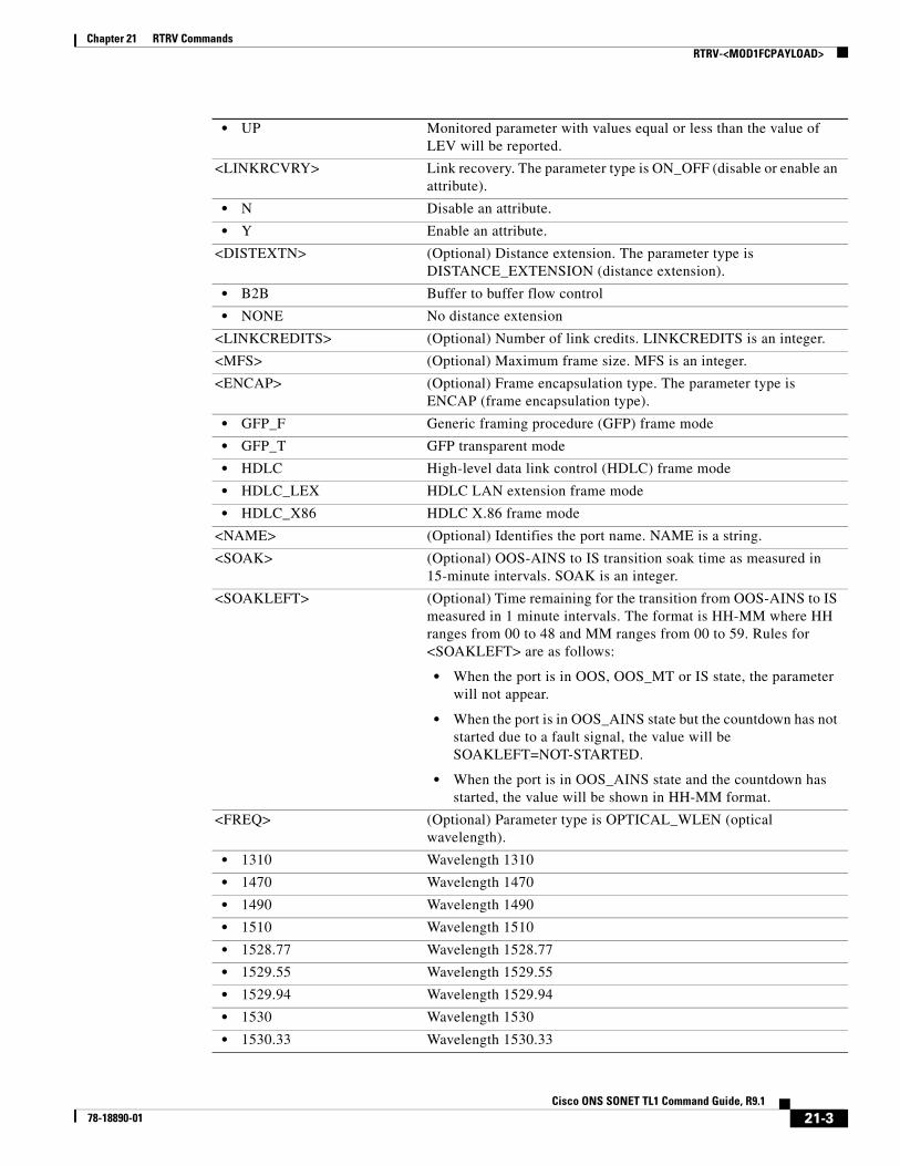
• UP Monitored parameter with values equal or less than the value of LEV will be reported.
<LINKRCVRY> Link recovery. The parameter type is ON_OFF (disable or enable an attribute).
• N Disable an attribute.
• Y Enable an attribute.
<DISTEXTN> (Optional) Distance extension. The parameter type is DISTANCE_EXTENSION (distance extension).
• B2B Buffer to buffer flow control
• NONE No distance extension
<LINKCREDITS> (Optional) Number of link credits. LINKCREDITS is an integer.
<MFS> (Optional) Maximum frame size. MFS is an integer.
<ENCAP> (Optional) Frame encapsulation type. The parameter type is ENCAP (frame encapsulation type).
• GFP_F Generic framing procedure (GFP) frame mode
• GFP_T GFP transparent mode
• HDLC High-level data link control (HDLC) frame mode
• HDLC_LEX HDLC LAN extension frame mode
• HDLC_X86 HDLC X.86 frame mode
<NAME> (Optional) Identifies the port name. NAME is a string.
<SOAK> (Optional) OOS-AINS to IS transition soak time as measured in 15-minute intervals. SOAK is an integer.
<SOAKLEFT> (Optional) Time remaining for the transition from OOS-AINS to IS measured in 1 minute intervals. The format is HH-MM where HH ranges from 00 to 48 and MM ranges from 00 to 59. Rules for <SOAKLEFT> are as follows:
• When the port is in OOS, OOS_MT or IS state, the parameter will not appear.
• When the port is in OOS_AINS state but the countdown has not started due to a fault signal, the value will be SOAKLEFT=NOT-STARTED.
• When the port is in OOS_AINS state and the countdown has started, the value will be shown in HH-MM format.
<FREQ> (Optional) Parameter type is OPTICAL_WLEN (optical wavelength).
• 1310 Wavelength 1310
• 1470 Wavelength 1470
• 1490 Wavelength 1490
• 1510 Wavelength 1510
• 1528.77 Wavelength 1528.77
• 1529.55 Wavelength 1529.55
• 1529.94 Wavelength 1529.94
• 1530 Wavelength 1530
• 1530.33 Wavelength 1530.33
21-3Cisco ONS SONET TL1 Command Guide, R9.1
78-18890-01

Chapter 21 RTRV CommandsRTRV-<MOD1FCPAYLOAD>
• 1530.73 Wavelength 1530.73
• 1531.12 Wavelength 1531.12
• 1531.51 Wavelength 1531.51
• 1531.90 Wavelength 1531.90
• 1532.29 Wavelength 1532.29
• 1532.68 Wavelength 1532.68
• 1533.07 Wavelength 1533.07
• 1533.47 Wavelength 1533.47
• 1533.86 Wavelength 1533.86
• 1534.25 Wavelength 1534.25
• 1534.64 Wavelength 1534.64
• 1535.04 Wavelength 1535.04
• 1535.43 Wavelength 1535.43
• 1535.82 Wavelength 1535.82
• 1536.22 Wavelength 1536.22
• 1536.61 Wavelength 1536.61
• 1537 Wavelength 1537
• 1537.40 Wavelength 1537.40
• 1537.79 Wavelength 1537.79
• 1538.19 Wavelength 1538.19
• 1538.58 Wavelength 1538.58
• 1538.98 Wavelength 1538.98
• 1539.37 Wavelength 1539.37
• 1539.77 Wavelength 1539.77
• 1540.16 Wavelength 1540.16
• 1540.56 Wavelength 1540.56
• 1540.95 Wavelength 1540.95
• 1541.35 Wavelength 1541.35
• 1541.75 Wavelength 1541.75
• 1542.14 Wavelength 1542.14
• 1542.35 Wavelength 1542.35
• 1542.54 Wavelength 1542.54
• 1542.94 Wavelength 1542.94
• 1543.33 Wavelength 1543.33
• 1543.73 Wavelength 1543.73
• 1544.13 Wavelength 1544.13
• 1544.53 Wavelength 1544.53
• 1544.92 Wavelength 1544.92
• 1545.32 Wavelength 1545.32
• 1545.72 Wavelength 1545.72
• 1546.12 Wavelength 1546.12
21-4Cisco ONS SONET TL1 Command Guide, R9.1
78-18890-01

Chapter 21 RTRV CommandsRTRV-<MOD1FCPAYLOAD>
• 1546.52 Wavelength 1546.52
• 1546.92 Wavelength 1546.92
• 1547.32 Wavelength 1547.32
• 1547.72 Wavelength 1547.72
• 1548.12 Wavelength 1548.12
• 1548.51 Wavelength 1548.51
• 1548.92 Wavelength 1548.92
• 1549.32 Wavelength 1549.32
• 1549.71 Wavelength 1549.71
• 1550 Wavelength 1500
• 1550.12 Wavelength 1550.12
• 1550.52 Wavelength 1550.52
• 1550.92 Wavelength 1550.92
• 1551.32 Wavelength 1551.32
• 1551.72 Wavelength 1551.72
• 1552.12 Wavelength 1552.12
• 1552.52 Wavelength 1552.52
• 1552.93 Wavelength 1552.93
• 1553.33 Wavelength 1553.33
• 1553.73 Wavelength 1553.73
• 1554.13 Wavelength 1554.13
• 1554.13 Wavelength 1554.13
• 1554.94 Wavelength 1554.94
• 1555.34 Wavelength 1555.34
• 1555.75 Wavelength 1555.75
• 1556.15 Wavelength 1556.15
• 1556.55 Wavelength 1556.55
• 1556.96 Wavelength 1556.96
• 1557.36 Wavelength 1557.36
• 1557.77 Wavelength 1557.77
• 1558.17 Wavelength 1558.17
• 1558.58 Wavelength 1558.58
• 1558.98 Wavelength 1558.98
• 1559.39 Wavelength 1559.39
• 1559.79 Wavelength 1559.79
• 1560.20 Wavelength 1560.20
• 1560.61 Wavelength 1560.61
• 1561.01 Wavelength 1561.01
• 1561.42 Wavelength 1561.42
• 1561.83 Wavelength 1561.83
• 1570 Wavelength 1570
21-5Cisco ONS SONET TL1 Command Guide, R9.1
78-18890-01
Chapter 21 RTRV CommandsRTRV-<MOD1FCPAYLOAD>
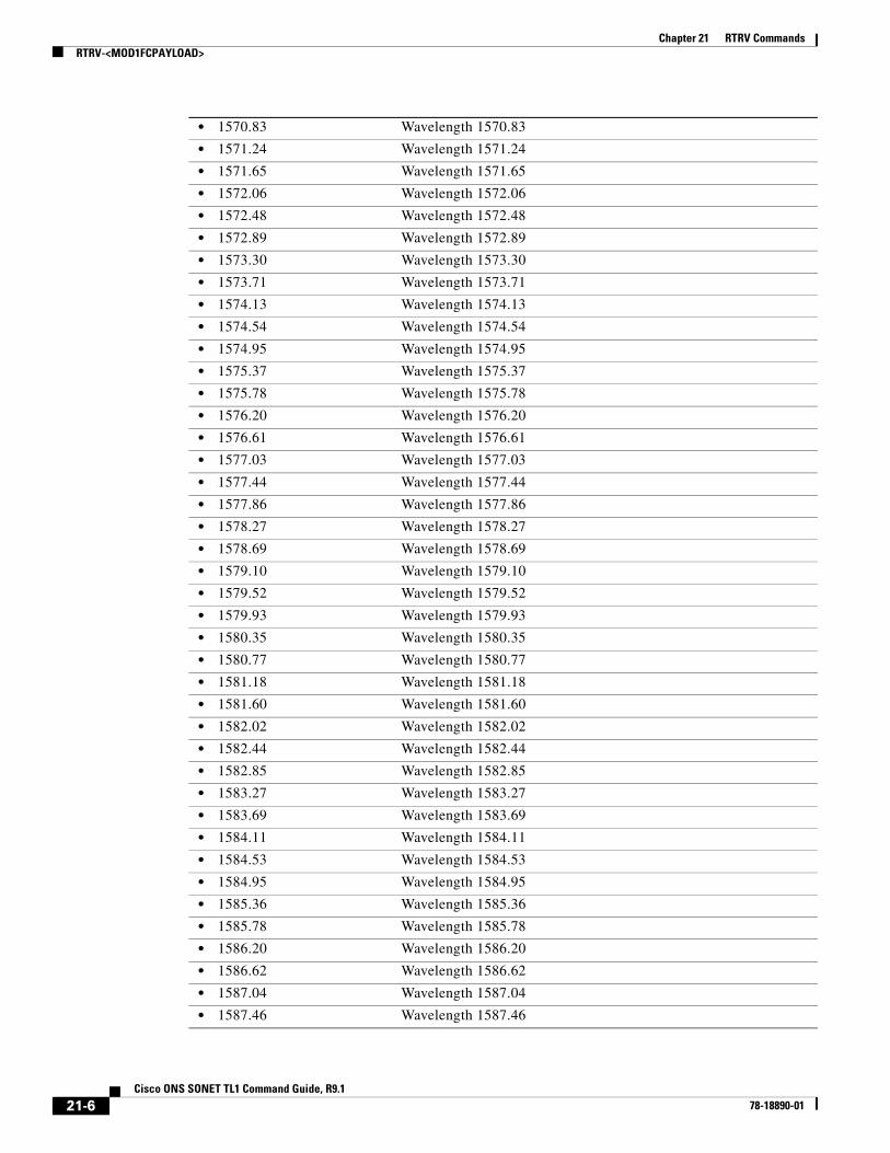
• 1570.83 Wavelength 1570.83
• 1571.24 Wavelength 1571.24
• 1571.65 Wavelength 1571.65
• 1572.06 Wavelength 1572.06
• 1572.48 Wavelength 1572.48
• 1572.89 Wavelength 1572.89
• 1573.30 Wavelength 1573.30
• 1573.71 Wavelength 1573.71
• 1574.13 Wavelength 1574.13
• 1574.54 Wavelength 1574.54
• 1574.95 Wavelength 1574.95
• 1575.37 Wavelength 1575.37
• 1575.78 Wavelength 1575.78
• 1576.20 Wavelength 1576.20
• 1576.61 Wavelength 1576.61
• 1577.03 Wavelength 1577.03
• 1577.44 Wavelength 1577.44
• 1577.86 Wavelength 1577.86
• 1578.27 Wavelength 1578.27
• 1578.69 Wavelength 1578.69
• 1579.10 Wavelength 1579.10
• 1579.52 Wavelength 1579.52
• 1579.93 Wavelength 1579.93
• 1580.35 Wavelength 1580.35
• 1580.77 Wavelength 1580.77
• 1581.18 Wavelength 1581.18
• 1581.60 Wavelength 1581.60
• 1582.02 Wavelength 1582.02
• 1582.44 Wavelength 1582.44
• 1582.85 Wavelength 1582.85
• 1583.27 Wavelength 1583.27
• 1583.69 Wavelength 1583.69
• 1584.11 Wavelength 1584.11
• 1584.53 Wavelength 1584.53
• 1584.95 Wavelength 1584.95
• 1585.36 Wavelength 1585.36
• 1585.78 Wavelength 1585.78
• 1586.20 Wavelength 1586.20
• 1586.62 Wavelength 1586.62
• 1587.04 Wavelength 1587.04
• 1587.46 Wavelength 1587.46
21-6Cisco ONS SONET TL1 Command Guide, R9.1
78-18890-01

Chapter 21 RTRV CommandsRTRV-<MOD1FCPAYLOAD>
• 1587.88 Wavelength 1587.88
• 1588.30 Wavelength 1588.30
• 1588.73 Wavelength 1588.73
• 1589.15 Wavelength 1589.15
• 1589.57 Wavelength 1589.57
• 1589.99 Wavelength 1589.99
• 1590 Wavelength 1590
• 1590.41 Wavelength 1590.41
• 1590.83 Wavelength 1590.83
• 1591.26 Wavelength 1591.26
• 1591.68 Wavelength 1591.68
• 1592.10 Wavelength 1592.10
• 1592.52 Wavelength 1592.52
• 1592.95 Wavelength 1592.95
• 1593.37 Wavelength 1593.37
• 1593.79 Wavelength 1593.79
• 1594.22 Wavelength 1594.22
• 1594.64 Wavelength 1594.64
• 1595.06 Wavelength 1595.06
• 1595.49 Wavelength 1595.49
• 1596.34 Wavelength 1596.34
• 1596.76 Wavelength 1596.76
• 1597.19 Wavelength 1597.19
• 1597.62 Wavelength 1597.62
• 1598.04 Wavelength 1598.04
• 1598.47 Wavelength 1598.47
• 1598.89 Wavelength 1598.89
• 1599.32 Wavelength 1599.32
• 1599.75 Wavelength 1599.75
• 1600.06 Wavelength 1600.06
• 1601.03 Wavelength 1601.03
• 1601.46 Wavelength 1601.46
• 1601.88 Wavelength 1601.88
• 1602.31 Wavelength 1602.31
• 1602.74 Wavelength 1602.74
• 1603.17 Wavelength 1603.17
• 1603.60 Wavelength 1603.60
• 1604.03 Wavelength 1604.03
• 1610 Wavelength 1610
• USE-TWL1 Use Tunable Wavelength 1
<LOSSB> (Optional) Parameter type is REACH (reach values).
21-7Cisco ONS SONET TL1 Command Guide, R9.1
78-18890-01
Chapter 21 RTRV CommandsRTRV-<MOD1FCPAYLOAD>
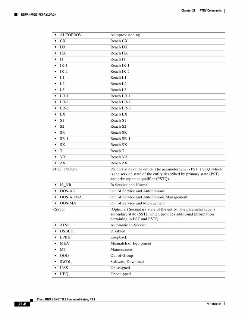
• AUTOPROV Autoprovisioning
• CX Reach CX
• DX Reach DX
• HX Reach HX
• I1 Reach I1
• IR-1 Reach IR-1
• IR-2 Reach IR-2
• L1 Reach L1
• L2 Reach L2
• L3 Reach L3
• LR-1 Reach LR-1
• LR-2 Reach LR-2
• LR-3 Reach LR-3
• LX Reach LX
• S1 Reach S1
• S2 Reach S2
• SR Reach SR
• SR-1 Reach SR-1
• SX Reach SX
• T Reach T
• VX Reach VX
• ZX Reach ZX
<PST_PSTQ> Primary state of the entity. The parameter type is PST_PSTQ, which is the service state of the entity described by primary state (PST) and primary state qualifier (PSTQ).
• IS_NR In Service and Normal
• OOS-AU Out of Service and Autonomous
• OOS-AUMA Out of Service and Autonomous Management
• OOS-MA Out of Service and Management
<SST> (Optional) Secondary state of the entity. The parameter type is secondary state (SST), which provides additional information pertaining to PST and PSTQ.
• AINS Automatic In-Service
• DSBLD Disabled
• LPBK Loopback
• MEA Mismatch of Equipment
• MT Maintenance
• OOG Out of Group
• SWDL Software Download
• UAS Unassigned
• UEQ Unequipped
21-8Cisco ONS SONET TL1 Command Guide, R9.1
78-18890-01

Chapter 21 RTRV CommandsRTRV-<MOD1FICONPAYLOAD>
21.2 RTRV-<MOD1FICONPAYLOAD>(Cisco ONS 15454) The Retrieve 1GFICON, 2GFICON, or 4GFICON (RTRV-<MOD1FICONPAYLOAD>) command returns Fibre Channel-specific settings for ports that have been configured to carry FICON traffic using the ENT-FICON command.
Usage Guidelines The MXPP_MR_2.5G card only supports the GFP-T frame type.
See Table 28-1 on page 1 for supported modifiers by platform.
Category Ports
Security Retrieve
Input Format RTRV-<MOD1FICONPAYLOAD>:[<TID>]:<AID>:<CTAG>;
Input Example RTRV-1GFICON:CISCO:FAC-1-1:123;
Input Parameters
Output Format SID DATE TIMEM CTAG COMPLD “<AID>:,,[<ROLE>],[<STATUS>]:[LINKRATE=<LINKRATE>],[LINKSTATE=<LINKSTATE>], [LINKRCVRY=<LINKRCVRY>],[DISTEXTN=<DISTEXTN>], [LINKCREDITS=<LINKCREDITS>],[MFS=<MFS>],[ENCAP=<ENCAP>],[NAME=<NAME>], [SOAK=<SOAK>],[SOAKLEFT=<SOAKLEFT>],[FREQ=<FREQ>],[LOSSB=<LOSSB>]: <PST_PSTQ>,<SST>”;
Output Example TID-000 1998-06-20 14:30:00M 001 COMPLD “FAC-1-1:,,WORK,ACT:LINKRATE=1GFICON,LINKSTATE=UP,LINKRCVRY=Y, DISTEXTN=NONE,LINKCREDITS=0,MFS=2148,ENCAP=GFP-T,NAME=\"FC PORT\", SOAK=32,SOAKLEFT=\"12-25\",FREQ=1550,LOSSB=LR-1:OOS-MA,MT”;
Output Parameters
<AID> Access identifier from the “26.15 FACILITY” section on page 35.
<AID> Access identifier from the “26.15 FACILITY” section on page 35.
<ROLE> (Optional) The port role in Y-cable protection (WORK or PROT). The parameter type is SIDE, which is the role that the unit is playing in the protection group.
21-9Cisco ONS SONET TL1 Command Guide, R9.1
78-18890-01

Chapter 21 RTRV CommandsRTRV-<MOD1FICONPAYLOAD>
• PROT The entity is a protection unit in the protection group.
• WORK The entity is a working unit in the protection group.
<STATUS> (Optional) A port status in Y-cable protection (ACT or STBY). The parameter type is STATUS, which is the status of the unit in the protection pair.
• ACT The entity is the active unit in the shelf.
• NA Status is unavailable.
• STBY The entity is the standby unit in the shelf.
<LINKRATE> The actual rate running on the Fibre Channel port. It can differ from the payload type provisioned. The parameter type is LINKRATE, which is the link rate on a Fibre Channel port.
• 1GFC 1-Gigabit Fibre Channel payload
• 1GFICON 1-Gigabit fiber connectivity payload
• 2GFC 2-Gigabit Fibre Channel payload
• 2GFICON 2-Gigabit fiber connectivity payload
• UNKNOWN The rate is unknown.
• UNPLUGGED The SFP is not plugged into the Fibre Channel port so the link rate cannot be detected.
<LINKSTATE> Link state. The parameter type is DIRN, which specifies the discriminating level for the requested monitored parameter.
• DN Monitored parameter with values equal to or greater than the level of LEV will be reported.
• UP Monitored parameter with values equal or less than the value of LEV will be reported.
<LINKRCVRY> Link recovery. The parameter type is ON_OFF (disable or enable an attribute).
• N Disable an attribute.
• Y Enable an attribute.
<DISTEXTN> (Optional) Distance extension. The parameter type is DISTANCE_EXTENSION (distance extension).
• B2B Buffer to buffer flow control
• NONE No distance extension
<LINKCREDITS> (Optional) Number of link credits. LINKCREDITS is an integer.
<MFS> (Optional) Maximum frame size. MFS is an integer.
<ENCAP> (Optional) Frame encapsulation type. The parameter type is ENCAP (frame encapsulation type).
• GFP_F GFP frame mode
• GFP_T GFP transparent mode
• HDLC HDLC frame mode
• HDLC_LEX HDLC LAN extension frame mode
• HDLC_X86 HDLC X.86 frame mode
<NAME> (Optional) Identifies the port name. NAME is a string.
<SOAK> (Optional) OOS-AINS to IS transition soak time as measured in 15-minute intervals. SOAK is an integer.
21-10Cisco ONS SONET TL1 Command Guide, R9.1
78-18890-01

Chapter 21 RTRV CommandsRTRV-<MOD1FICONPAYLOAD>
<SOAKLEFT> (Optional) Time remaining for the transition from OOS-AINS to IS measured in 1 minute intervals. The format is HH-MM where HH ranges from 00 to 48 and MM ranges from 00 to 59. Rules for <SOAKLEFT> are as follows:
• When the port is in OOS, OOS_MT, or IS state, the parameter will not appear.
• When the port is in OOS_AINS state but the countdown has not started due to a fault signal, the value will be SOAKLEFT=NOT-STARTED.
• When the port is in OOS_AINS state and the countdown has started, the value will be shown in HH-MM format.
<FREQ> (Optional) Parameter type is OPTICAL_WLEN (optical wavelength).
• 1310 Wavelength 1310
• 1470 Wavelength 1470
• 1490 Wavelength 1490
• 1510 Wavelength 1510
• 1528.77 Wavelength 1528.77
• 1529.55 Wavelength 1529.55
• 1529.94 Wavelength 1529.94
• 1530 Wavelength 1530
• 1530.33 Wavelength 1530.33
• 1530.73 Wavelength 1530.73
• 1531.12 Wavelength 1531.12
• 1531.51 Wavelength 1531.51
• 1531.90 Wavelength 1531.90
• 1532.29 Wavelength 1532.29
• 1532.68 Wavelength 1532.68
• 1533.07 Wavelength 1533.07
• 1533.47 Wavelength 1533.47
• 1533.86 Wavelength 1533.86
• 1534.25 Wavelength 1534.25
• 1534.64 Wavelength 1534.64
• 1535.04 Wavelength 1535.04
• 1535.43 Wavelength 1535.43
• 1535.82 Wavelength 1535.82
• 1536.22 Wavelength 1536.22
• 1536.61 Wavelength 1536.61
• 1537 Wavelength 1537
• 1537.40 Wavelength 1537.40
• 1537.79 Wavelength 1537.79
• 1538.19 Wavelength 1538.19
• 1538.58 Wavelength 1538.58
21-11Cisco ONS SONET TL1 Command Guide, R9.1
78-18890-01

Chapter 21 RTRV CommandsRTRV-<MOD1FICONPAYLOAD>
• 1538.98 Wavelength 1538.98
• 1539.37 Wavelength 1539.37
• 1539.77 Wavelength 1539.77
• 1540.16 Wavelength 1540.16
• 1540.56 Wavelength 1540.56
• 1540.95 Wavelength 1540.95
• 1541.35 Wavelength 1541.35
• 1541.75 Wavelength 1541.75
• 1542.14 Wavelength 1542.14
• 1542.35 Wavelength 1542.35
• 1542.54 Wavelength 1542.54
• 1542.94 Wavelength 1542.94
• 1543.33 Wavelength 1543.33
• 1543.73 Wavelength 1543.73
• 1544.13 Wavelength 1544.13
• 1544.53 Wavelength 1544.53
• 1544.92 Wavelength 1544.92
• 1545.32 Wavelength 1545.32
• 1545.72 Wavelength 1545.72
• 1546.12 Wavelength 1546.12
• 1546.52 Wavelength 1546.52
• 1546.92 Wavelength 1546.92
• 1547.32 Wavelength 1547.32
• 1547.72 Wavelength 1547.72
• 1548.12 Wavelength 1548.12
• 1548.51 Wavelength 1548.51
• 1548.92 Wavelength 1548.92
• 1549.32 Wavelength 1549.32
• 1549.71 Wavelength 1549.71
• 1550 Wavelength 1500
• 1550.12 Wavelength 1550.12
• 1550.52 Wavelength 1550.52
• 1550.92 Wavelength 1550.92
• 1551.32 Wavelength 1551.32
• 1551.72 Wavelength 1551.72
• 1552.12 Wavelength 1552.12
• 1552.52 Wavelength 1552.52
• 1552.93 Wavelength 1552.93
• 1553.33 Wavelength 1553.33
• 1553.73 Wavelength 1553.73
• 1554.13 Wavelength 1554.13
21-12Cisco ONS SONET TL1 Command Guide, R9.1
78-18890-01

Chapter 21 RTRV CommandsRTRV-<MOD1FICONPAYLOAD>
• 1554.13 Wavelength 1554.13
• 1554.94 Wavelength 1554.94
• 1555.34 Wavelength 1555.34
• 1555.75 Wavelength 1555.75
• 1556.15 Wavelength 1556.15
• 1556.55 Wavelength 1556.55
• 1556.96 Wavelength 1556.96
• 1557.36 Wavelength 1557.36
• 1557.77 Wavelength 1557.77
• 1558.17 Wavelength 1558.17
• 1558.58 Wavelength 1558.58
• 1558.98 Wavelength 1558.98
• 1559.39 Wavelength 1559.39
• 1559.79 Wavelength 1559.79
• 1560.20 Wavelength 1560.20
• 1560.61 Wavelength 1560.61
• 1561.01 Wavelength 1561.01
• 1561.42 Wavelength 1561.42
• 1561.83 Wavelength 1561.83
• 1570 Wavelength 1570
• 1570.83 Wavelength 1570.83
• 1571.24 Wavelength 1571.24
• 1571.65 Wavelength 1571.65
• 1572.06 Wavelength 1572.06
• 1572.48 Wavelength 1572.48
• 1572.89 Wavelength 1572.89
• 1573.30 Wavelength 1573.30
• 1573.71 Wavelength 1573.71
• 1574.13 Wavelength 1574.13
• 1574.54 Wavelength 1574.54
• 1574.95 Wavelength 1574.95
• 1575.37 Wavelength 1575.37
• 1575.78 Wavelength 1575.78
• 1576.20 Wavelength 1576.20
• 1576.61 Wavelength 1576.61
• 1577.03 Wavelength 1577.03
• 1577.44 Wavelength 1577.44
• 1577.86 Wavelength 1577.86
• 1578.27 Wavelength 1578.27
• 1578.69 Wavelength 1578.69
• 1579.10 Wavelength 1579.10
21-13Cisco ONS SONET TL1 Command Guide, R9.1
78-18890-01

Chapter 21 RTRV CommandsRTRV-<MOD1FICONPAYLOAD>
• 1579.52 Wavelength 1579.52
• 1579.93 Wavelength 1579.93
• 1580.35 Wavelength 1580.35
• 1580.77 Wavelength 1580.77
• 1581.18 Wavelength 1581.18
• 1581.60 Wavelength 1581.60
• 1582.02 Wavelength 1582.02
• 1582.44 Wavelength 1582.44
• 1582.85 Wavelength 1582.85
• 1583.27 Wavelength 1583.27
• 1583.69 Wavelength 1583.69
• 1584.11 Wavelength 1584.11
• 1584.53 Wavelength 1584.53
• 1584.95 Wavelength 1584.95
• 1585.36 Wavelength 1585.36
• 1585.78 Wavelength 1585.78
• 1586.20 Wavelength 1586.20
• 1586.62 Wavelength 1586.62
• 1587.04 Wavelength 1587.04
• 1587.46 Wavelength 1587.46
• 1587.88 Wavelength 1587.88
• 1588.30 Wavelength 1588.30
• 1588.73 Wavelength 1588.73
• 1589.15 Wavelength 1589.15
• 1589.57 Wavelength 1589.57
• 1589.99 Wavelength 1589.99
• 1590 Wavelength 1590
• 1590.41 Wavelength 1590.41
• 1590.83 Wavelength 1590.83
• 1591.26 Wavelength 1591.26
• 1591.68 Wavelength 1591.68
• 1592.10 Wavelength 1592.10
• 1592.52 Wavelength 1592.52
• 1592.95 Wavelength 1592.95
• 1593.37 Wavelength 1593.37
• 1593.79 Wavelength 1593.79
• 1594.22 Wavelength 1594.22
• 1594.64 Wavelength 1594.64
• 1595.06 Wavelength 1595.06
• 1595.49 Wavelength 1595.49
• 1596.34 Wavelength 1596.34
21-14Cisco ONS SONET TL1 Command Guide, R9.1
78-18890-01

Chapter 21 RTRV CommandsRTRV-<MOD1FICONPAYLOAD>
• 1596.76 Wavelength 1596.76
• 1597.19 Wavelength 1597.19
• 1597.62 Wavelength 1597.62
• 1598.04 Wavelength 1598.04
• 1598.47 Wavelength 1598.47
• 1598.89 Wavelength 1598.89
• 1599.32 Wavelength 1599.32
• 1599.75 Wavelength 1599.75
• 1600.06 Wavelength 1600.06
• 1601.03 Wavelength 1601.03
• 1601.46 Wavelength 1601.46
• 1601.88 Wavelength 1601.88
• 1602.31 Wavelength 1602.31
• 1602.74 Wavelength 1602.74
• 1603.17 Wavelength 1603.17
• 1603.60 Wavelength 1603.60
• 1604.03 Wavelength 1604.03
• 1610 Wavelength 1610
• USE-TWL1 Use Tunable Wavelength 1
<LOSSB> (Optional) Parameter type is REACH (reach values).
• AUTOPROV Autoprovisioning
• CX Reach CX
• DX Reach DX
• HX Reach HX
• I1 Reach I1
• IR-1 Reach IR-1
• IR-2 Reach IR-2
• L1 Reach L1
• L2 Reach L2
• L3 Reach L3
• LR-1 Reach LR-1
• LR-2 Reach LR-2
• LR-3 Reach LR-3
• LX Reach LX
• S1 Reach S1
• S2 Reach S2
• SR Reach SR
• SR-1 Reach SR-1
• SX Reach SX
• T Reach T
• VX Reach VX
21-15Cisco ONS SONET TL1 Command Guide, R9.1
78-18890-01

Chapter 21 RTRV CommandsRTRV-<MOD2DWDMPAYLOAD>
21.3 RTRV-<MOD2DWDMPAYLOAD>(Cisco ONS 15454) The Retrieve D1VIDEO, DV6000, DVBASI, ETRCLO, HDTV, ISCCOMPAT, ISC1, ISC3PEER2R, ISC3PEER1G, ISC3PEER2G and PASSTHRU (RTRV-<MOD2DWDMPAYLOAD>) command retrieves the configuration parameter of a dense wavelength division multiplexing (DWDM) client.
Usage Guidelines See Table 28-1 on page 1 for supported modifiers by platform.
Category DWDM
Security Retrieve
Input Format RTRV-<MOD2DWDMPAYLOAD>:[<TID>]:<AID>:<CTAG>[::::];
Input Example RTRV-HDTV:MILAN:FAC-1-1:100;
Input Parameters
• ZX Reach ZX
<PST_PSTQ> Primary state of the entity. The parameter type is PST_PSTQ, which is the service state of the entity described by the PST and PSTQ.
• IS_NR In Service and Normal
• OOS-AU Out of Service and Autonomous
• OOS-AUMA Out of Service and Autonomous Management
• OOS-MA Out of Service and Management
<SST> (Optional) Secondary state of the entity. The parameter type is SST, which provides additional information pertaining to PST and PSTQ.
• AINS Automatic In-Service
• DSBLD Disabled
• LPBK Loopback
• MEA Mismatch of Equipment
• MT Maintenance
• OOG Out of Group
• SWDL Software Download
• UAS Unassigned
• UEQ Unequipped
<AID> Access identifier from the “26.15 FACILITY” section on page 35.
21-16Cisco ONS SONET TL1 Command Guide, R9.1
78-18890-01

Chapter 21 RTRV CommandsRTRV-<MOD2DWDMPAYLOAD>
Output Format SID DATE TIMEM CTAG COMPLD “<AIDUNIONID>,<AIDTYPE>:,,[<ROLE>],[<STATUS>]:[NAME=<NAME>],[LBCL=<LBCL>], [OPT=<OPT>],[OPR=<OPR>],[FREQ=<FREQ>],[LOSSB=<LOSSB>]:<PSTPSTQ>,[<SST>]”
;
Output Example TID-000 1998-06-20 14:30:00M 001 COMPLD “FAC-1-1-1,HDTV:,,WORK,ACT:NAME=\"NY PORT\",LBCL=10.0,OPT=10.0,OPR=10.0, FREQ=1550,LOSSB=LR-1:OOS-AU,AINS”;
Output Parameters <AIDUNIONID> Access identifier from the “26.2 AidUnionId” section on page 12
<AIDTYPE> A type of access identifier. The parameter type is MOD2DWDMPAYLOAD, which contains the payload types applicable to DWDM ports.
• 10GFC 10-Gigabit Fibre Channel payload
• 10GIGE 10-Gigabit Ethernet
• 40GIGE 40-Gigabit Ethernet
• 1GFC 1-Gigabit Fibre Channel payload
• 1GFICON 1-Gigabit fiber connectivity payload
• 2GFC 2-Gigabit Fibre Channel payload
• 2GFICON 2-Gigabit fiber connectivity payload
• 5GIB 5Gbps InfiniBand payload
• 8GFC 8-Gigabit Fibre Channel payload
• D1VIDEO D1Video payload
• DV6000 DV6000 payload
• DVBASI DVBASI payload
• ETRCLO ETR_CLO payload
• GIGE Gigabit Ethernet payload
• HDTV High definition television (HDTV) payload
• ISC1 ISC1 payload
• ISC3 ISC3 payload
• OTU3 Optical Transport Unit Level 3
• PASSTHRU Any pass-through (2R) payload
<ROLE> (Optional) The port role in Y-cable protection (WORK or PROT). The parameter type is SIDE, which is the role the unit is playing in the protection group.
• PROT The entity is a protection unit in the protection group.
• WORK The entity is a working unit in the protection group.
21-17Cisco ONS SONET TL1 Command Guide, R9.1
78-18890-01
Chapter 21 RTRV CommandsRTRV-<MOD2DWDMPAYLOAD>
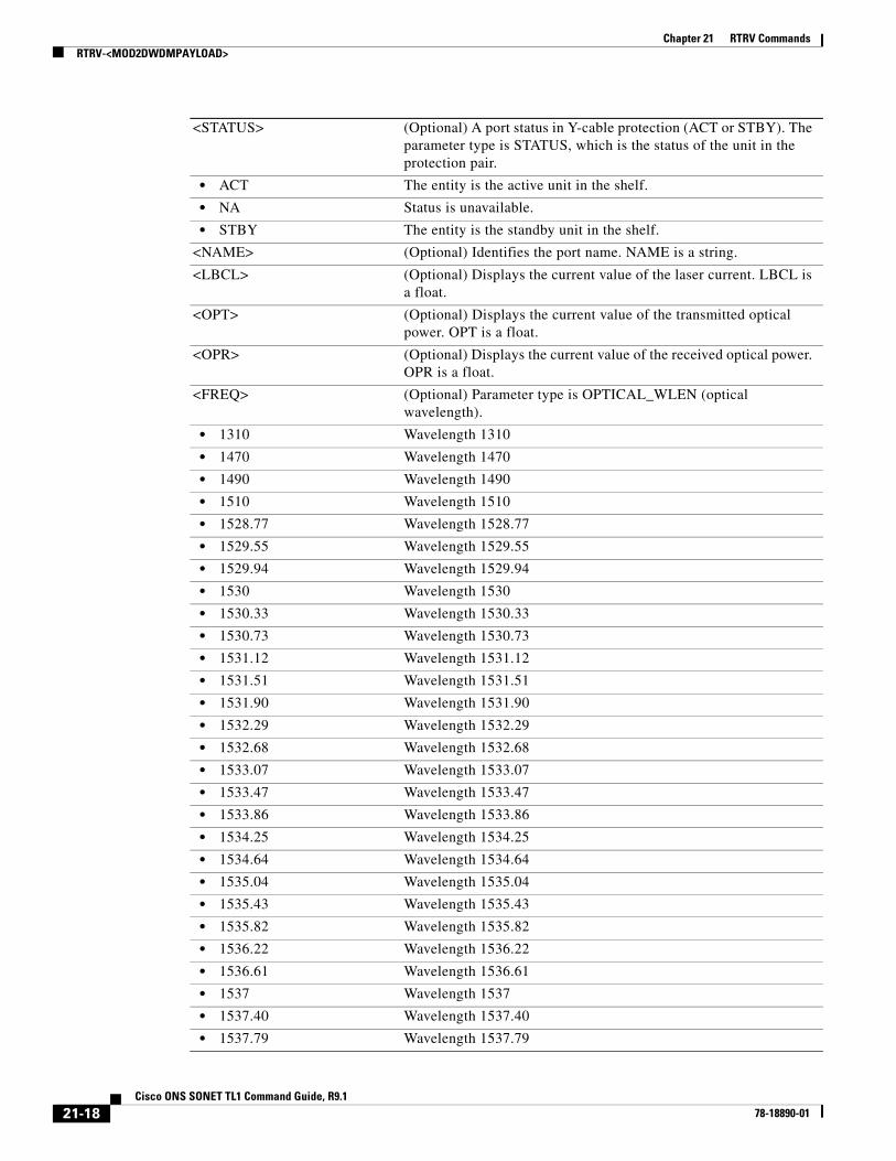
<STATUS> (Optional) A port status in Y-cable protection (ACT or STBY). The parameter type is STATUS, which is the status of the unit in the protection pair.
• ACT The entity is the active unit in the shelf.
• NA Status is unavailable.
• STBY The entity is the standby unit in the shelf.
<NAME> (Optional) Identifies the port name. NAME is a string.
<LBCL> (Optional) Displays the current value of the laser current. LBCL is a float.
<OPT> (Optional) Displays the current value of the transmitted optical power. OPT is a float.
<OPR> (Optional) Displays the current value of the received optical power. OPR is a float.
<FREQ> (Optional) Parameter type is OPTICAL_WLEN (optical wavelength).
• 1310 Wavelength 1310
• 1470 Wavelength 1470
• 1490 Wavelength 1490
• 1510 Wavelength 1510
• 1528.77 Wavelength 1528.77
• 1529.55 Wavelength 1529.55
• 1529.94 Wavelength 1529.94
• 1530 Wavelength 1530
• 1530.33 Wavelength 1530.33
• 1530.73 Wavelength 1530.73
• 1531.12 Wavelength 1531.12
• 1531.51 Wavelength 1531.51
• 1531.90 Wavelength 1531.90
• 1532.29 Wavelength 1532.29
• 1532.68 Wavelength 1532.68
• 1533.07 Wavelength 1533.07
• 1533.47 Wavelength 1533.47
• 1533.86 Wavelength 1533.86
• 1534.25 Wavelength 1534.25
• 1534.64 Wavelength 1534.64
• 1535.04 Wavelength 1535.04
• 1535.43 Wavelength 1535.43
• 1535.82 Wavelength 1535.82
• 1536.22 Wavelength 1536.22
• 1536.61 Wavelength 1536.61
• 1537 Wavelength 1537
• 1537.40 Wavelength 1537.40
• 1537.79 Wavelength 1537.79
21-18Cisco ONS SONET TL1 Command Guide, R9.1
78-18890-01

Chapter 21 RTRV CommandsRTRV-<MOD2DWDMPAYLOAD>
• 1538.19 Wavelength 1538.19
• 1538.58 Wavelength 1538.58
• 1538.98 Wavelength 1538.98
• 1539.37 Wavelength 1539.37
• 1539.77 Wavelength 1539.77
• 1540.16 Wavelength 1540.16
• 1540.56 Wavelength 1540.56
• 1540.95 Wavelength 1540.95
• 1541.35 Wavelength 1541.35
• 1541.75 Wavelength 1541.75
• 1542.14 Wavelength 1542.14
• 1542.35 Wavelength 1542.35
• 1542.54 Wavelength 1542.54
• 1542.94 Wavelength 1542.94
• 1543.33 Wavelength 1543.33
• 1543.73 Wavelength 1543.73
• 1544.13 Wavelength 1544.13
• 1544.53 Wavelength 1544.53
• 1544.92 Wavelength 1544.92
• 1545.32 Wavelength 1545.32
• 1545.72 Wavelength 1545.72
• 1546.12 Wavelength 1546.12
• 1546.52 Wavelength 1546.52
• 1546.92 Wavelength 1546.92
• 1547.32 Wavelength 1547.32
• 1547.72 Wavelength 1547.72
• 1548.12 Wavelength 1548.12
• 1548.51 Wavelength 1548.51
• 1548.92 Wavelength 1548.92
• 1549.32 Wavelength 1549.32
• 1549.71 Wavelength 1549.71
• 1550 Wavelength 1500
• 1550.12 Wavelength 1550.12
• 1550.52 Wavelength 1550.52
• 1550.92 Wavelength 1550.92
• 1551.32 Wavelength 1551.32
• 1551.72 Wavelength 1551.72
• 1552.12 Wavelength 1552.12
• 1552.52 Wavelength 1552.52
• 1552.93 Wavelength 1552.93
• 1553.33 Wavelength 1553.33
21-19Cisco ONS SONET TL1 Command Guide, R9.1
78-18890-01

Chapter 21 RTRV CommandsRTRV-<MOD2DWDMPAYLOAD>
• 1553.73 Wavelength 1553.73
• 1554.13 Wavelength 1554.13
• 1554.13 Wavelength 1554.13
• 1554.94 Wavelength 1554.94
• 1555.34 Wavelength 1555.34
• 1555.75 Wavelength 1555.75
• 1556.15 Wavelength 1556.15
• 1556.55 Wavelength 1556.55
• 1556.96 Wavelength 1556.96
• 1557.36 Wavelength 1557.36
• 1557.77 Wavelength 1557.77
• 1558.17 Wavelength 1558.17
• 1558.58 Wavelength 1558.58
• 1558.98 Wavelength 1558.98
• 1559.39 Wavelength 1559.39
• 1559.79 Wavelength 1559.79
• 1560.20 Wavelength 1560.20
• 1560.61 Wavelength 1560.61
• 1561.01 Wavelength 1561.01
• 1561.42 Wavelength 1561.42
• 1561.83 Wavelength 1561.83
• 1570 Wavelength 1570
• 1570.83 Wavelength 1570.83
• 1571.24 Wavelength 1571.24
• 1571.65 Wavelength 1571.65
• 1572.06 Wavelength 1572.06
• 1572.48 Wavelength 1572.48
• 1572.89 Wavelength 1572.89
• 1573.30 Wavelength 1573.30
• 1573.71 Wavelength 1573.71
• 1574.13 Wavelength 1574.13
• 1574.54 Wavelength 1574.54
• 1574.95 Wavelength 1574.95
• 1575.37 Wavelength 1575.37
• 1575.78 Wavelength 1575.78
• 1576.20 Wavelength 1576.20
• 1576.61 Wavelength 1576.61
• 1577.03 Wavelength 1577.03
• 1577.44 Wavelength 1577.44
• 1577.86 Wavelength 1577.86
• 1578.27 Wavelength 1578.27
21-20Cisco ONS SONET TL1 Command Guide, R9.1
78-18890-01

Chapter 21 RTRV CommandsRTRV-<MOD2DWDMPAYLOAD>
• 1578.69 Wavelength 1578.69
• 1579.10 Wavelength 1579.10
• 1579.52 Wavelength 1579.52
• 1579.93 Wavelength 1579.93
• 1580.35 Wavelength 1580.35
• 1580.77 Wavelength 1580.77
• 1581.18 Wavelength 1581.18
• 1581.60 Wavelength 1581.60
• 1582.02 Wavelength 1582.02
• 1582.44 Wavelength 1582.44
• 1582.85 Wavelength 1582.85
• 1583.27 Wavelength 1583.27
• 1583.69 Wavelength 1583.69
• 1584.11 Wavelength 1584.11
• 1584.53 Wavelength 1584.53
• 1584.95 Wavelength 1584.95
• 1585.36 Wavelength 1585.36
• 1585.78 Wavelength 1585.78
• 1586.20 Wavelength 1586.20
• 1586.62 Wavelength 1586.62
• 1587.04 Wavelength 1587.04
• 1587.46 Wavelength 1587.46
• 1587.88 Wavelength 1587.88
• 1588.30 Wavelength 1588.30
• 1588.73 Wavelength 1588.73
• 1589.15 Wavelength 1589.15
• 1589.57 Wavelength 1589.57
• 1589.99 Wavelength 1589.99
• 1590 Wavelength 1590
• 1590.41 Wavelength 1590.41
• 1590.83 Wavelength 1590.83
• 1591.26 Wavelength 1591.26
• 1591.68 Wavelength 1591.68
• 1592.10 Wavelength 1592.10
• 1592.52 Wavelength 1592.52
• 1592.95 Wavelength 1592.95
• 1593.37 Wavelength 1593.37
• 1593.79 Wavelength 1593.79
• 1594.22 Wavelength 1594.22
• 1594.64 Wavelength 1594.64
• 1595.06 Wavelength 1595.06
21-21Cisco ONS SONET TL1 Command Guide, R9.1
78-18890-01

Chapter 21 RTRV CommandsRTRV-<MOD2DWDMPAYLOAD>
• 1595.49 Wavelength 1595.49
• 1596.34 Wavelength 1596.34
• 1596.76 Wavelength 1596.76
• 1597.19 Wavelength 1597.19
• 1597.62 Wavelength 1597.62
• 1598.04 Wavelength 1598.04
• 1598.47 Wavelength 1598.47
• 1598.89 Wavelength 1598.89
• 1599.32 Wavelength 1599.32
• 1599.75 Wavelength 1599.75
• 1600.06 Wavelength 1600.06
• 1601.03 Wavelength 1601.03
• 1601.46 Wavelength 1601.46
• 1601.88 Wavelength 1601.88
• 1602.31 Wavelength 1602.31
• 1602.74 Wavelength 1602.74
• 1603.17 Wavelength 1603.17
• 1603.60 Wavelength 1603.60
• 1604.03 Wavelength 1604.03
• 1610 Wavelength 1610
• USE-TWL1 Use Tunable Wavelength 1
<LOSSB> (Optional) Parameter type is REACH (reach values).
• AUTOPROV Autoprovisioning
• CX Reach CX
• DX Reach DX
• HX Reach HX
• I1 Reach I1
• IR-1 Reach IR-1
• IR-2 Reach IR-2
• L1 Reach L1
• L2 Reach L2
• L3 Reach L3
• LR-1 Reach LR-1
• LR-2 Reach LR-2
• LR-3 Reach LR-3
• LX Reach LX
• S1 Reach S1
• S2 Reach S2
• SR Reach SR
• SR-1 Reach SR-1
• SX Reach SX
21-22Cisco ONS SONET TL1 Command Guide, R9.1
78-18890-01

Chapter 21 RTRV CommandsRTRV-<MOD_RING>
21.4 RTRV-<MOD_RING>(Cisco ONS 15454 and ONS 15600) The Retrieve Bidirectional Line Switched Ring (RTRV-<MOD_RING>) command retrieves the bidirectional line switched ring (BLSR) information of the NE. A two-fiber or four-fiber BLSR can be retrieved.
Note Cisco ONS 15600 does not support four-fiber BLSR.
Usage Guidelines Output examples:
4F BLSR:
“BLSR-N43AB::RINGID=N43AB,NODEID=3,MODE=4F,RVRTV=Y,RVTM=5.0,SRVRTV=Y,SRVTM=5.0,EASTWORK=FAC-5-1,WESTWORK=FAC-6-1,EASTPROT=FAC-12-1,WESTPROT=FAC-13-1”
2F BLSR:
“BLSR-N12EF::RINGID=N12EF,NODEID=2,MODE=2F,RVRTV=Y,RVTM=5.0,EASTWORK=FAC-5-1,WESTWORK=FAC-6-1”
• The following actions will return error messages:
– If the system fails on getting IOR, a SROF (Get IOR Failed) error message is returned.
– If the AID is invalid, an IIAC (Invalid AID) error message is returned.
• T Reach T
• VX Reach VX
• ZX Reach ZX
<PST_PSTQ> Primary state of the entity. The parameter type is PST_PSTQ, which is the service state of the entity described by the PST and PSTQ.
• IS_NR In Service and Normal
• OOS-AU Out of Service and Autonomous
• OOS-AUMA Out of Service and Autonomous Management
• OOS-MA Out of Service and Management
<SST> (Optional) Secondary state of the entity. The parameter type is SST, which provides additional information pertaining to PST and PSTQ.
• AINS Automatic In-Service
• DSBLD Disabled
• LPBK Loopback
• MEA Mismatch of Equipment
• MT Maintenance
• OOG Out of Group
• SWDL Software Download
• UAS Unassigned
• UEQ Unequipped
21-23Cisco ONS SONET TL1 Command Guide, R9.1
78-18890-01

Chapter 21 RTRV CommandsRTRV-<MOD_RING>
– If the BLSR does not exist, a SRQN (BLSR Does Not Exist) error message is returned.
• Only ALL, NULL, BLSR-ALL, or BLSR-RINGID is allowed for this command.
• A NULL AID defaults to the AID ALL.
• The list AID format is supported.
Category BLSR
Security Retrieve
Input Format RTRV-<MOD_RING>:[<TID>]:[<AID>]:<CTAG>[::::];
Input Example RTRV-BLSR:PETALUMA:ALL:123;
Input Parameters
Output Format SID DATE TIMEM CTAG COMPLD “[<AID>]::[RINGID=<RINGID>],[NODEID=<NODEID>],[MODE=<MODE>], [RVRTV=<RVRTV>],[RVTM=<RVTM>],[SRVRTV=<SRVRTV>],[SRVTM=<SRVTM>], [EASTWORK=<EASTWORK>],[WESTWORK=<WESTWORK>],[EASTPROT=<EASTPROT>], [WESTPROT=<WESTPROT>]”
;
Output Example TID-000 1998-06-20 14:30:00M 001 COMPLD “BLSR-43::RINGID=43,NODEID=3,MODE=4F,RVRTV=Y,RVTM=5.0,SRVRTV=Y,SRVTM=5.0, EASTWORK=FAC-5-1,WESTWORK=FAC-6-1,EASTPROT=FAC-12-1,WESTPROT=FAC-13-1”;
Output Parameters
<AID> Access identifier from the “26.3 AidUnionId1” section on page 17. Identifies the BLSR of the NE. Only ALL, null, or a list of BLSR-# is allowed. A null value is equivalent to ALL.
<AID> (Optional) Access identifier from the “26.3 AidUnionId1” section on page 17. Identifies the BLSR of the NE.
<RINGID> (Optional) The BLSR ID of the NE. String of up to six characters. Valid characters are A-Z and 0-9.
<NODEID> (Optional) The BLSR node ID of the NE. NODEID is a string and ranges from 0 to 31.
21-24Cisco ONS SONET TL1 Command Guide, R9.1
78-18890-01

Chapter 21 RTRV CommandsRTRV-<OCN_TYPE>
21.5 RTRV-<OCN_TYPE>(Cisco ONS 15454, 15327, 15600, 15310) The Retrieve OC3, OC12, OC48, or OC192 command retrieves the attributes (for example, service parameters) and the state of an OC-N facility.
Usage Guidelines See Table 28-1 on page 1 for supported modifiers by platform.
Both RINGID and BLSRTYPE identify the OC-N port connected with a BLSR. These attributes are only presented for the OC-12, OC-48, and OC-192 ports within a BLSR connection. The RTRV-<MOD_RING> command with the AID BLSR-RINGID can provide more information about a BLSR.
<MODE> (Optional) Mode with which the command is to be implemented. Identifies the BLSR mode; either two-fiber or four-fiber. The parameter type is BLSR_MODE (BLSR mode).
• 2F Two-fiber BLSR
• 4F Four-fiber BLSR
<RVRTV> (Optional) Revertive mode. The value Y indicates that protection switching system reverts service to the original line after restoration. The value N indicates that protection switching system does not revert service to the original line after restoration. RVRTV is applicable only for 1+1 protection switching. Null defaults to N. The parameter type is ON_OFF (disable or enable an attribute).
• N Does not revert service to original line after restoration.
• Y Reverts service to original line after restoration.
<RVTM> Revertive time. RVTM is not allowed to be set while RVRTV is N. The parameter type is REVERTIVE_TIME.
• 0.5 to 12.0 Revertive time is 0.5 to 12.0 minutes.
<SRVRTV> The span revertive mode for four-fiber BLSR only. The parameter type is ON_OFF (disable or enable an attribute).
• N Disable an attribute.
• Y Enable an attribute.
<SRVTM> The span revertive time for four-fiber BLSR only. SRVTM is not allowed to be set while SRVRTV is N. The parameter type is REVERTIVE_TIME.
• 0.5 to 12.0 Revertive time is 0.5 to 12.0 minutes.
<EASTWORK> East working facility. AID from the “26.15 FACILITY” section on page 35.
<WESTWORK> West working facility. AID from the “26.15 FACILITY” section on page 35.
<EASTPROT> East protecting facility. AID from the “26.15 FACILITY” section on page 35.
<WESTPROT> West protecting facility. AID from the “26.15 FACILITY” section on page 35.
21-25Cisco ONS SONET TL1 Command Guide, R9.1
78-18890-01
Chapter 21 RTRV CommandsRTRV-<OCN_TYPE>
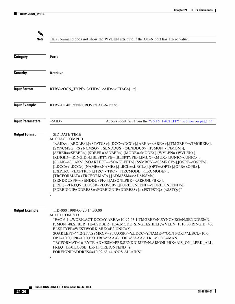
Note This command does not show the WVLEN attribute if the OC-N port has a zero value.
Category Ports
Security Retrieve
Input Format RTRV-<OCN_TYPE>:[<TID>]:<AID>:<CTAG>[::::];
Input Example RTRV-OC48:PENNGROVE:FAC-6-1:236;
Input Parameters
Output Format SID DATE TIMEM CTAG COMPLD “<AID>:,,[<ROLE>],[<STATUS>]:[DCC=<DCC>],[AREA=<AREA>],[TMGREF=<TMGREF>], [SYNCMSG=<SYNCMSG>],[SENDDUS=<SENDDUS>],[PJMON=<PJMON>], [SFBER=<SFBER>],[SDBER=<SDBER>],[MODE=<MODE>],[WVLEN=<WVLEN>], [RINGID=<RINGID>],[BLSRTYPE=<BLSRTYPE>],[MUX=<MUX>],[UNIC=<UNIC>], [SOAK=<SOAK>],[SOAKLEFT=<SOAKLEFT>],[SSMRCV=<SSMRCV>],[OSPF=<OSPF>], [LDCC=<LDCC>],[NAME=<NAME>],[LBCL=<LBCL>],[OPT=<OPT>],[OPR=<OPR>], [EXPTRC=<EXPTRC>],[TRC=<TRC>],[TRCMODE=<TRCMODE>], [TRCFORMAT=<TRCFORMAT>],[ADMSSM=<ADMSSM>], [SENDDUSFF=<SENDDUSFF>],[AISONLPBK=<AISONLPBK>], [FREQ=<FREQ>],[LOSSB=<LOSSB>],[FOREIGNFEND=<FOREIGNFEND>], [FOREIGNIPADDRESS=<FOREIGNIPADDRESS>],:<PSTPSTQ>,[<SSTQ>]”;
Output Example TID-000 1998-06-20 14:30:00M 001 COMPLD “FAC-6-1:,,WORK,ACT:DCC=Y,AREA=10.92.63.1,TMGREF=N,SYNCMSG=N,SENDDUS=N, PJMON=48,SFBER=1E-4,SDBER=1E-6,MODE=SINGLESHELF,WVLEN=1310.00,RINGID=43, BLSRTYPE=WESTWORK,MUX=E2,UNIC=Y, SOAKLEFT=\"12-25\",SSMRCV=STU,OSPF=Y,LDCC=Y,NAME=\"OCN PORT\",LBCL=10.0, OPT=10.0,OPR=10.0,EXPTRC=\"AAA\",TRC=\"AAA\",TRCMODE=MAN, TRCFORMAT=16-BYTE,ADMSSM=PRS,SENDDUSFF=N,AISONLPBK=AIS_ON_LPBK_ALL, FREQ=1550,LOSSB=LR-1,FOREIGNFEND=Y, FOREIGNIPADDRESS=10.92.63.44,:OOS-AU,AINS”;
<AID> Access identifier from the “26.15 FACILITY” section on page 35.
21-26Cisco ONS SONET TL1 Command Guide, R9.1
78-18890-01

Chapter 21 RTRV CommandsRTRV-<OCN_TYPE>
Output Parameters <AID> Access identifier from the “26.15 FACILITY” section on page 35.
<ROLE> (Optional) An OC-N port role. The parameter type is SIDE, which is the role the unit is playing in the protection group.
• PROT The entity is a protection unit in the protection group.
• WORK The entity is a working unit in the protection group.
<STATUS> (Optional) An OC-N port status. The parameter type is STATUS, which is the status of the unit in the protection pair.
• ACT The entity is the active unit in the shelf.
• NA Status is unavailable.
• STBY The entity is the standby unit in the shelf.
<DCC> (Optional) Indicates whether or not the Section data communications channel (DCC) is to be used. The parameter type is EXT_RING, which indicates whether the ring supports the extended K1/K2/K3 protocol.
• N The ring does not support the extended K1/K2/K3 protocol.
• Y The ring does support the extended K1/K2/K3 protocol.
<AREA> (Optional) Area ID. Shows up only if the DCC is enabled. AREA is a string.
<TMGREF> (Optional) The termination to be used, whether primary or secondary. Identifies if an OC-N port has a timing reference. Defaults to N. The parameter type is ON_OFF (disable or enable an attribute).
• N Disable an attribute.
• Y Enable an attribute.
<SYNCMSG> Synchronization status message. The parameter type is EXT_RING, which indicates whether the ring supports the extended K1/K2/K3 protocol.
• N The ring does not support the extended K1/K2/K3 protocol.
• Y The ring does support the extended K1/K2/K3 protocol.
<SENDDUS> (Optional) The facility will send the DUS (Do not use for Synchronization) value in 0x0f bits pattern as the synchronization status message for that facility. Defaults to N. The parameter type is ON_OFF (disable or enable an attribute).
• N Disable an attribute.
• Y Enable an attribute.
<PJMON> (Optional) Identifies an OC-N port PJMON. Defaults to 0 (zero). PJMON is an integer. Set a valid STS number of the optical port.
Note The PJMON number displayed in TL1 interface does not correspond to the PJVC4MON number in CTC, but instead corresponds to the STS number of the optical port.
<SFBER> (Optional) An OC-N port signal failure threshold. Defaults to 1E-4. The parameter type is SF_BER, which is the threshold for declaring signal failure on a facility or path.
• 1E-3 SFBER is 1E-3.
• 1E-4 SFBER is 1E-4.
21-27Cisco ONS SONET TL1 Command Guide, R9.1
78-18890-01

Chapter 21 RTRV CommandsRTRV-<OCN_TYPE>
• 1E-5 SFBER is 1E-5.
<SDBER> (Optional) An OC-N port signal degrade threshold. Defaults 1E-7. The parameter type is SD_BER, which is the threshold for declaring signal degrade on a facility or path.
• 1E-5 SDBER is 1E-5.
• 1E-6 SDBER is 1E-6.
• 1E-7 SDBER is 1E-7.
• 1E-8 SDBER is 1E-8.
• 1E-9 SDBER is 1E-9.
<MODE> (Optional) OC-N port mode. Defaults to SONET. The parameter type is OPTICAL_MODE, which is the facility’s optical mode.
• SINGLESHELF The NE contains only one shelf and the AID representation does not consider the shelf identifier for command requests/response and autonomous reports.
• MULTISHELF The AID representation considers the shelf identifier for command requests/response and autonomous reports. This means the NE has more than one shelf configured or the user wants to use the new AID style.
• MULTISHELFETH The AID representation considers the shelf identifier for command requests/response and autonomous reports. This means the NE has more than one shelf configured or the user wants to use the new AID style. The shelves are connected by means of an external Ethernet switch.
<WVLEN> (Optional) An OC-N port wavelength in nanometers. For example, WVLEN=1310.00 means it operates at 1310 nm in the DWDM application. WVLEN is a float.
<RINGID> (Optional) The BLSR RINGID with which the port is connected. RINGID ranges from 0 to 9999. RINGID is an integer.
<BLSRTYPE> (Optional) The BLSR type with which the port is connected. The parameter type is BLSR_TYPE, which is the BLSR type of an OC-N port.
• EASTPROT The OC-N port is an east protecting port.
• EASTWORK The OC-N port is an east working port.
• WESTPROT The OC-N port is an west protecting port.
• WESTWORK The OC-N port is an west working port.
<MUX> (Optional) BLSR extension byte. The parameter type is MUX_TYPE, which is the BLSR extension byte.
• E2 E2 byte (orderwire)
• F1 F1 byte (user)
• K3 K3 byte
• Z2 Z2 byte
<UNIC> (Optional) Indicates if the port connects to the UCP. The parameter type is ON_OFF (disable or enable an attribute).
21-28Cisco ONS SONET TL1 Command Guide, R9.1
78-18890-01

Chapter 21 RTRV CommandsRTRV-<OCN_TYPE>
• N Disable an attribute.
• Y Enable an attribute.
<SOAK> (Optional) OOS-AINS to IS transition soak time as measured in 15-minute intervals. SOAK is an integer.
<SOAKLEFT> (Optional) Time remaining for the transition from OOS-AINS to IS measured in 1-minute intervals. The format is HH-MM where HH ranges from 00 to 48 and MM ranges from 00 to 59. Rules for <SOAKLEFT> are as follows:
• When the port is in OOS, OOS_MT, or IS state, the parameter will not appear.
• When the port is in OOS_AINS but the countdown has not started due to a fault signal, the value will be SOAKLEFT=NOT-STARTED.
• When the port is in OOS_AINS state and the countdown has started, the value will be shown in HH-MM format.
<SSMRCV> (Optional) Displays the quality of the individual port. The parameter type is SYNC_CLOCK_REF_QUALITY_LEVEL, which is the clock source quality level for SONET.
• DUS Do Not Use For Synchronization
• PRS Primary Reference Source, Stratum 1 Traceable
• RES Reserved For Network Synchronization Use
• SMC SONET Minimum Clock Traceable
• ST2 Stratum 2 Traceable
• ST3 Stratum 3 Traceable
• ST3E Stratum 3E Traceable
• ST4 Stratum 4 Traceable
• STU Synchronized, Traceability Unknown
• TNC Transit Node Clock (2nd Generation Only)
<OSPF> (Optional) The Open Shortest Path First protocol. The parameter type is ON_OFF (disable or enable an attribute).
• N Disable an attribute.
• Y Enable an attribute.
<LDCC> (Optional) The Line DCC connection on the port. The parameter type is EXT_RING, which indicates if the ring supports the extended K1/K2/K3 protocol.
• N The ring does not support the extended K1/K2/K3 protocol.
• Y The ring does support the extended K1/K2/K3 protocol.
<NAME> (Optional) Port Name. NAME is a string.
<LBCL> (Optional) Displays the current value of the laser current. LBCL is a float.
<OPT> (Optional) Displays the current value of the transmitted optical power. OPT is only displayed for DWDM cards. OPT is a float.
<OPR> Received optical power. OPR is a float.
<EXPTRC> (Optional) Expected path trace content. EXPTRC is a string.
21-29Cisco ONS SONET TL1 Command Guide, R9.1
78-18890-01
Chapter 21 RTRV CommandsRTRV-<OCN_TYPE>
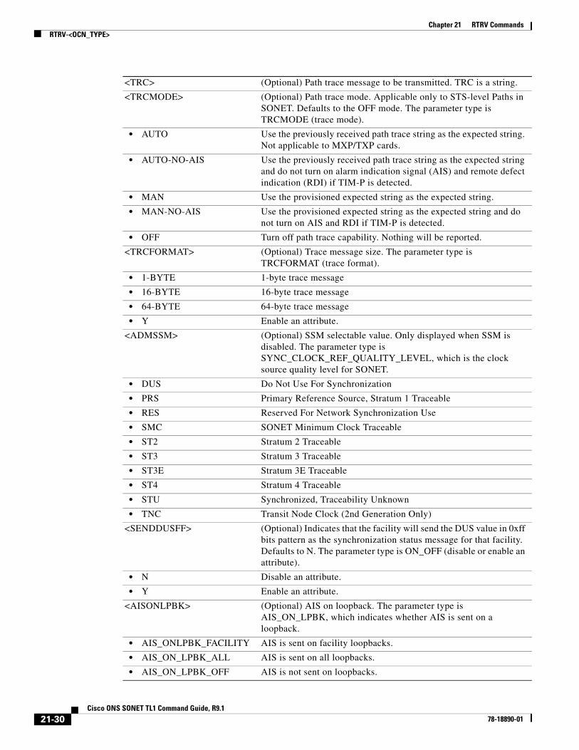
<TRC> (Optional) Path trace message to be transmitted. TRC is a string.
<TRCMODE> (Optional) Path trace mode. Applicable only to STS-level Paths in SONET. Defaults to the OFF mode. The parameter type is TRCMODE (trace mode).
• AUTO Use the previously received path trace string as the expected string. Not applicable to MXP/TXP cards.
• AUTO-NO-AIS Use the previously received path trace string as the expected string and do not turn on alarm indication signal (AIS) and remote defect indication (RDI) if TIM-P is detected.
• MAN Use the provisioned expected string as the expected string.
• MAN-NO-AIS Use the provisioned expected string as the expected string and do not turn on AIS and RDI if TIM-P is detected.
• OFF Turn off path trace capability. Nothing will be reported.
<TRCFORMAT> (Optional) Trace message size. The parameter type is TRCFORMAT (trace format).
• 1-BYTE 1-byte trace message
• 16-BYTE 16-byte trace message
• 64-BYTE 64-byte trace message
• Y Enable an attribute.
<ADMSSM> (Optional) SSM selectable value. Only displayed when SSM is disabled. The parameter type is SYNC_CLOCK_REF_QUALITY_LEVEL, which is the clock source quality level for SONET.
• DUS Do Not Use For Synchronization
• PRS Primary Reference Source, Stratum 1 Traceable
• RES Reserved For Network Synchronization Use
• SMC SONET Minimum Clock Traceable
• ST2 Stratum 2 Traceable
• ST3 Stratum 3 Traceable
• ST3E Stratum 3E Traceable
• ST4 Stratum 4 Traceable
• STU Synchronized, Traceability Unknown
• TNC Transit Node Clock (2nd Generation Only)
<SENDDUSFF> (Optional) Indicates that the facility will send the DUS value in 0xff bits pattern as the synchronization status message for that facility. Defaults to N. The parameter type is ON_OFF (disable or enable an attribute).
• N Disable an attribute.
• Y Enable an attribute.
<AISONLPBK> (Optional) AIS on loopback. The parameter type is AIS_ON_LPBK, which indicates whether AIS is sent on a loopback.
• AIS_ONLPBK_FACILITY AIS is sent on facility loopbacks.
• AIS_ON_LPBK_ALL AIS is sent on all loopbacks.
• AIS_ON_LPBK_OFF AIS is not sent on loopbacks.
21-30Cisco ONS SONET TL1 Command Guide, R9.1
78-18890-01

Chapter 21 RTRV CommandsRTRV-<OCN_TYPE>
• AIS_ON_LPBK_TERMINAL AIS is sent on terminal loopbacks.
<FREQ> (Optional) Parameter type is OPTICAL_WLEN (optical wavelength).
• 1310 Wavelength 1310
• 1470 Wavelength 1470
• 1490 Wavelength 1490
• 1510 Wavelength 1510
• 1528.77 Wavelength 1528.77
• 1529.55 Wavelength 1529.55
• 1529.94 Wavelength 1529.94
• 1530 Wavelength 1530
• 1530.33 Wavelength 1530.33
• 1530.73 Wavelength 1530.73
• 1531.12 Wavelength 1531.12
• 1531.51 Wavelength 1531.51
• 1531.90 Wavelength 1531.90
• 1532.29 Wavelength 1532.29
• 1532.68 Wavelength 1532.68
• 1533.07 Wavelength 1533.07
• 1533.47 Wavelength 1533.47
• 1533.86 Wavelength 1533.86
• 1534.25 Wavelength 1534.25
• 1534.64 Wavelength 1534.64
• 1535.04 Wavelength 1535.04
• 1535.43 Wavelength 1535.43
• 1535.82 Wavelength 1535.82
• 1536.22 Wavelength 1536.22
• 1536.61 Wavelength 1536.61
• 1537 Wavelength 1537
• 1537.40 Wavelength 1537.40
• 1537.79 Wavelength 1537.79
• 1538.19 Wavelength 1538.19
• 1538.58 Wavelength 1538.58
• 1538.98 Wavelength 1538.98
• 1539.37 Wavelength 1539.37
• 1539.77 Wavelength 1539.77
• 1540.16 Wavelength 1540.16
• 1540.56 Wavelength 1540.56
• 1540.95 Wavelength 1540.95
• 1541.35 Wavelength 1541.35
• 1541.75 Wavelength 1541.75
• 1542.14 Wavelength 1542.14
21-31Cisco ONS SONET TL1 Command Guide, R9.1
78-18890-01

Chapter 21 RTRV CommandsRTRV-<OCN_TYPE>
• 1542.35 Wavelength 1542.35
• 1542.54 Wavelength 1542.54
• 1542.94 Wavelength 1542.94
• 1543.33 Wavelength 1543.33
• 1543.73 Wavelength 1543.73
• 1544.13 Wavelength 1544.13
• 1544.53 Wavelength 1544.53
• 1544.92 Wavelength 1544.92
• 1545.32 Wavelength 1545.32
• 1545.72 Wavelength 1545.72
• 1546.12 Wavelength 1546.12
• 1546.52 Wavelength 1546.52
• 1546.92 Wavelength 1546.92
• 1547.32 Wavelength 1547.32
• 1547.72 Wavelength 1547.72
• 1548.12 Wavelength 1548.12
• 1548.51 Wavelength 1548.51
• 1548.92 Wavelength 1548.92
• 1549.32 Wavelength 1549.32
• 1549.71 Wavelength 1549.71
• 1550 Wavelength 1500
• 1550.12 Wavelength 1550.12
• 1550.52 Wavelength 1550.52
• 1550.92 Wavelength 1550.92
• 1551.32 Wavelength 1551.32
• 1551.72 Wavelength 1551.72
• 1552.12 Wavelength 1552.12
• 1552.52 Wavelength 1552.52
• 1552.93 Wavelength 1552.93
• 1553.33 Wavelength 1553.33
• 1553.73 Wavelength 1553.73
• 1554.13 Wavelength 1554.13
• 1554.13 Wavelength 1554.13
• 1554.94 Wavelength 1554.94
• 1555.34 Wavelength 1555.34
• 1555.75 Wavelength 1555.75
• 1556.15 Wavelength 1556.15
• 1556.55 Wavelength 1556.55
• 1556.96 Wavelength 1556.96
• 1557.36 Wavelength 1557.36
• 1557.77 Wavelength 1557.77
21-32Cisco ONS SONET TL1 Command Guide, R9.1
78-18890-01

Chapter 21 RTRV CommandsRTRV-<OCN_TYPE>
• 1558.17 Wavelength 1558.17
• 1558.58 Wavelength 1558.58
• 1558.98 Wavelength 1558.98
• 1559.39 Wavelength 1559.39
• 1559.79 Wavelength 1559.79
• 1560.20 Wavelength 1560.20
• 1560.61 Wavelength 1560.61
• 1561.01 Wavelength 1561.01
• 1561.42 Wavelength 1561.42
• 1561.83 Wavelength 1561.83
• 1570 Wavelength 1570
• 1570.83 Wavelength 1570.83
• 1571.24 Wavelength 1571.24
• 1571.65 Wavelength 1571.65
• 1572.06 Wavelength 1572.06
• 1572.48 Wavelength 1572.48
• 1572.89 Wavelength 1572.89
• 1573.30 Wavelength 1573.30
• 1573.71 Wavelength 1573.71
• 1574.13 Wavelength 1574.13
• 1574.54 Wavelength 1574.54
• 1574.95 Wavelength 1574.95
• 1575.37 Wavelength 1575.37
• 1575.78 Wavelength 1575.78
• 1576.20 Wavelength 1576.20
• 1576.61 Wavelength 1576.61
• 1577.03 Wavelength 1577.03
• 1577.44 Wavelength 1577.44
• 1577.86 Wavelength 1577.86
• 1578.27 Wavelength 1578.27
• 1578.69 Wavelength 1578.69
• 1579.10 Wavelength 1579.10
• 1579.52 Wavelength 1579.52
• 1579.93 Wavelength 1579.93
• 1580.35 Wavelength 1580.35
• 1580.77 Wavelength 1580.77
• 1581.18 Wavelength 1581.18
• 1581.60 Wavelength 1581.60
• 1582.02 Wavelength 1582.02
• 1582.44 Wavelength 1582.44
• 1582.85 Wavelength 1582.85
21-33Cisco ONS SONET TL1 Command Guide, R9.1
78-18890-01

Chapter 21 RTRV CommandsRTRV-<OCN_TYPE>
• 1583.27 Wavelength 1583.27
• 1583.69 Wavelength 1583.69
• 1584.11 Wavelength 1584.11
• 1584.53 Wavelength 1584.53
• 1584.95 Wavelength 1584.95
• 1585.36 Wavelength 1585.36
• 1585.78 Wavelength 1585.78
• 1586.20 Wavelength 1586.20
• 1586.62 Wavelength 1586.62
• 1587.04 Wavelength 1587.04
• 1587.46 Wavelength 1587.46
• 1587.88 Wavelength 1587.88
• 1588.30 Wavelength 1588.30
• 1588.73 Wavelength 1588.73
• 1589.15 Wavelength 1589.15
• 1589.57 Wavelength 1589.57
• 1589.99 Wavelength 1589.99
• 1590 Wavelength 1590
• 1590.41 Wavelength 1590.41
• 1590.83 Wavelength 1590.83
• 1591.26 Wavelength 1591.26
• 1591.68 Wavelength 1591.68
• 1592.10 Wavelength 1592.10
• 1592.52 Wavelength 1592.52
• 1592.95 Wavelength 1592.95
• 1593.37 Wavelength 1593.37
• 1593.79 Wavelength 1593.79
• 1594.22 Wavelength 1594.22
• 1594.64 Wavelength 1594.64
• 1595.06 Wavelength 1595.06
• 1595.49 Wavelength 1595.49
• 1596.34 Wavelength 1596.34
• 1596.76 Wavelength 1596.76
• 1597.19 Wavelength 1597.19
• 1597.62 Wavelength 1597.62
• 1598.04 Wavelength 1598.04
• 1598.47 Wavelength 1598.47
• 1598.89 Wavelength 1598.89
• 1599.32 Wavelength 1599.32
• 1599.75 Wavelength 1599.75
• 1600.06 Wavelength 1600.06
21-34Cisco ONS SONET TL1 Command Guide, R9.1
78-18890-01
Chapter 21 RTRV CommandsRTRV-<OCN_TYPE>
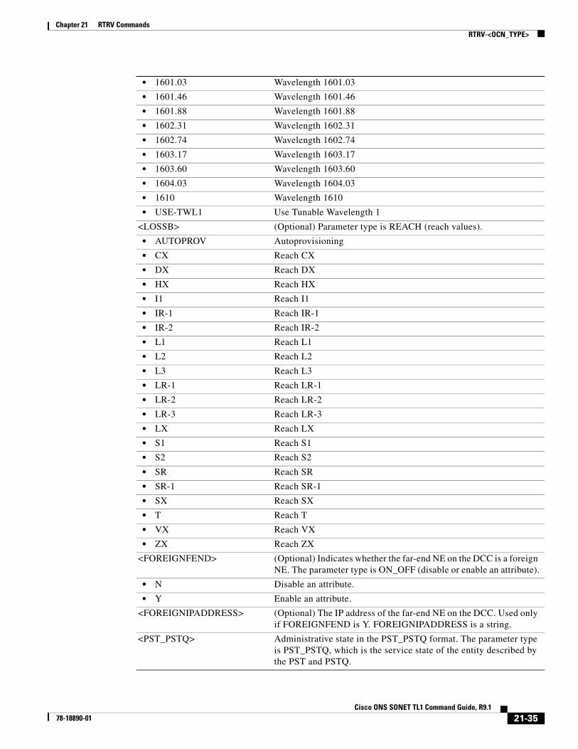
• 1601.03 Wavelength 1601.03
• 1601.46 Wavelength 1601.46
• 1601.88 Wavelength 1601.88
• 1602.31 Wavelength 1602.31
• 1602.74 Wavelength 1602.74
• 1603.17 Wavelength 1603.17
• 1603.60 Wavelength 1603.60
• 1604.03 Wavelength 1604.03
• 1610 Wavelength 1610
• USE-TWL1 Use Tunable Wavelength 1
<LOSSB> (Optional) Parameter type is REACH (reach values).
• AUTOPROV Autoprovisioning
• CX Reach CX
• DX Reach DX
• HX Reach HX
• I1 Reach I1
• IR-1 Reach IR-1
• IR-2 Reach IR-2
• L1 Reach L1
• L2 Reach L2
• L3 Reach L3
• LR-1 Reach LR-1
• LR-2 Reach LR-2
• LR-3 Reach LR-3
• LX Reach LX
• S1 Reach S1
• S2 Reach S2
• SR Reach SR
• SR-1 Reach SR-1
• SX Reach SX
• T Reach T
• VX Reach VX
• ZX Reach ZX
<FOREIGNFEND> (Optional) Indicates whether the far-end NE on the DCC is a foreign NE. The parameter type is ON_OFF (disable or enable an attribute).
• N Disable an attribute.
• Y Enable an attribute.
<FOREIGNIPADDRESS> (Optional) The IP address of the far-end NE on the DCC. Used only if FOREIGNFEND is Y. FOREIGNIPADDRESS is a string.
<PST_PSTQ> Administrative state in the PST_PSTQ format. The parameter type is PST_PSTQ, which is the service state of the entity described by the PST and PSTQ.
21-35Cisco ONS SONET TL1 Command Guide, R9.1
78-18890-01
Chapter 21 RTRV CommandsRTRV-<PATH>
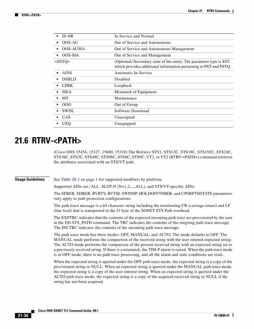
21.6 RTRV-<PATH>(Cisco ONS 15454, 15327, 15600, 15310) The Retrieve STS1, STS12C, STS18C, STS192C, STS24C, STS36C, STS3C, STS48C, STS96C, STS6C, STS9C, VT1, or VT2 (RTRV-<PATH>) command retrieves the attributes associated with an STS/VT path.
Usage Guidelines See Table 28-1 on page 1 for supported modifiers by platform.
Supported AIDs are: ALL, SLOT-N (N=1,2,...,ALL), and STS/VT-specific AIDs.
The SFBER, SDBER, RVRTV, RVTM, SWPDIP, HOLDOFFTIMER, and UPSRPTHSTATE parameters only apply to path protection configurations.
The path trace message is a 64 character string including the terminating CR (carriage return) and LF (line feed) that is transported in the J1 byte of the SONET STS Path overhead.
The EXPTRC indicates that the contents of the expected incoming path trace are provisioned by the user in the ED-STS_PATH command. The TRC indicates the contents of the outgoing path trace message. The INCTRC indicates the contents of the incoming path trace message.
The path trace mode has three modes: OFF, MANUAL, and AUTO. The mode defaults to OFF. The MANUAL mode performs the comparison of the received string with the user entered expected string. The AUTO mode performs the comparison of the present received string with an expected string set to a previously received string. If there is a mismatch, the TIM-P alarm is raised. When the path trace mode is in OFF mode, there is no path trace processing, and all the alarm and state conditions are reset.
When the expected string is queried under the OFF path trace mode, the expected string is a copy of the provisioned string or NULL. When an expected string is queried under the MANUAL path trace mode, the expected string is a copy of the user entered string. When an expected string is queried under the AUTO path trace mode, the expected string is a copy of the acquired received string or NULL if the string has not been acquired.
• IS-NR In Service and Normal
• OOS-AU Out of Service and Autonomous
• OOS-AUMA Out of Service and Autonomous Management
• OOS-MA Out of Service and Management
<SSTQ> (Optional) Secondary state of the entity. The parameter type is SST, which provides additional information pertaining to PST and PSTQ.
• AINS Automatic In-Service
• DSBLD Disabled
• LPBK Loopback
• MEA Mismatch of Equipment
• MT Maintenance
• OOG Out of Group
• SWDL Software Download
• UAS Unassigned
• UEQ Unequipped
21-36Cisco ONS SONET TL1 Command Guide, R9.1
78-18890-01

Chapter 21 RTRV CommandsRTRV-<PATH>
When the incoming string is queried under the OFF path trace mode, the incoming string is NULL. When an incoming string is queried under the MANUAL or AUTO path trace mode, the incoming string is a copy of the received string or NULL if the string has not been received.
J1 (EXPTRC) is implemented on the DS1/DS1N, DS3E/DS3NE, DS3XM, EC1, DS3/EC1-48, OC3, OC48AS, OC192, MRC-12, and OC192-XFP cards.
TRC and INCTRC are supported on DS1N, DS3NE, DS3/EC1-48, and DS3XM cards.
The following actions will result in error messages:
• If you send this command while BLSRPTHTYPE=PCA, whether there is a BLSR switch or not, the protection channel access (PCA) path J1/C2 data will be returned (if there is PCA circuit on the AID).
• Sending this command with an STS AID that does not have circuits and where no BLSR is switched on the STS will return an error message.
• In LAN to WAN card mode, ALL aid is not supported for RTRV-VC464c.
Note • An optional input parameter, BLSRPTHTYPE, is introduced into this command to provide more options to retrieve the J1/C2 of a particular BLSR path. This field is valid only if the queried AID port has BLSR. The BLSRPTHTYPE defaults to the “non-pca” path type if the BLSR is switched, or defaults to all BLSR path types if there is no BLSR switching.
• An optional output parameter, BLSRPTHSTATE, is introduced into this command output. Each J1/C2 output data of this command will include the BLSR path state information.
• After BLSR switching, the J1/IPPM/C2 data can be retrieved over the protection path. J1 trace string, trace mode, or threshold is not allowed on the protection path.
• HOLDOFFTIMER is not specific to a path. Instead, it is applicable to the path protection selector.
• VT1.5 J2 path trace provisioning is supported on the DS3XM-12 card and the ONS 15454 CE-100T-8 card VT1.5 path using the ED-VT1, RTRV-VT1, and RTRV-PTHTRC-VT1 commands. The ONS 15310-CL CE-100T-8 card supports J2 path trace.
• Test access is not supported on the ONS 15310-CL. J2 is not supported on the 15310-CL-CTX card of the ONS 15310-CL. However, the CE-100T-8 card supports J2 in the ONS 15310-CL.
• For the selector path on a BLSR, the SWPDIP path attribute is not editable and is always in the ON state.
• SFBER and SDBER are applied for the ONS 15310-CL and the ONS 15454 when the ONS 15454 has an XC-VXC-10G card.
• On the ONS 15310-MA, J2 path trace is supported on DS1 ports only. J2 path trace is not supported on ONS 15310-MA OCn ports and EC1 ports.
Category Paths
Security Retrieve
Input Format RTRV-<PATH>:[<TID>]:<AID>:<CTAG>[:::BLSRPTHTYPE=<BLSRPTHTYPE>][:];
21-37Cisco ONS SONET TL1 Command Guide, R9.1
78-18890-01

Chapter 21 RTRV CommandsRTRV-<PATH>
Input Example RTRV-STS3C:FERNDALE:STS-2-1-4:238:::BLSRPTHTYPE=NON-PCA;
Input Parameters
Output Format SID DATE TIMEM CTAG COMPLD “<AID>::[LEVEL=<LEVEL>],[SFBER=<SFBER>],[SDBER=<SDBER>],[RVRTV=<RVRTV>], [RVTM=<RVTM>],[SWPDIP=<SWPDIP>],[HOLDOFFTIMER=<HOLDOFFTIMER>], [EXPTRC=<EXPTRC>],[TRC=<TRC>],[INCTRC=<INCTRC>],[TRCMODE=<TRCMODE>], [TRCFORMAT =<TRCFORMAT>],[TACC=<TACC>],[TAPTYPE=<TAPTYPE>], [UPSRPTHSTATE=<UPSRPTHSTATE>],[C2=<C2>], [BLSRPTHSTATE=<BLSRPTHSTATE>]:<PST_PSTQ>,[<SSTQ>]”;
Output Example TID-000 1998-06-20 14:30:00M 001 COMPLD “STS-2-1-4::LEVEL=STS1,SFBER=1E-3,SDBER=1E-5,RVRTV=Y,RVTM=1.0,SWPDIP=Y, HOLDOFFTIMER=2000,EXPTRC=“EXPTRCSTRING”,TRC=“TRCSTRING”, INCTRC=“INCTRCSTRING”,TRCMODE=AUTO,TRCFORMAT=64-BYTE,TACC=8, TAPTYPE=DUAL,UPSRPTHSTATE=ACT,C2=0X04, BLSRPTHSTATE=PROTPTHACT:OOS-AU,AINS”;
Output Parameters
<AID> Access identifier from the “26.11 CrossConnectId1” section on page 26.
<BLSRPTHTYPE> The BLSR path type only if the port is on the BLSR. No value or a null value defaults to NON-PCA. Applicable only to STS-level paths in SONET. The parameter type is BLSR_PTH_TYPE, which is the BLSR path type only if the port is on the BLSR.
• NON-PCA The AID is on the working path, or the cross-connection card protection path.
• PCA The AID is on the BLSR PCA path.
<AID> Access identifier from the “26.11 CrossConnectId1” section on page 26.
<LEVEL> (Optional) The rate of the cross-connect. Indicates the rate of the cross-connected channel. Applicable only to the STS path in SONET. The parameter type is PATH, which is the modifier for path commands.
• STS1 Synchronous transport signal/module level 1 (51.84 Mbps)
• STS3C Synchronous transport signal/module level 3 concatenated (155.52 Mbps)
• STS6C Synchronous transport signal/module level 6 (311.04 Mbps)
• STS9C Synchronous transport signal/module level 9 concatenated (466.56 Mbps)
• STS12C Synchronous transport signal/module level 12 concatenated (622.08 Mbps)
21-38Cisco ONS SONET TL1 Command Guide, R9.1
78-18890-01
Chapter 21 RTRV CommandsRTRV-<PATH>
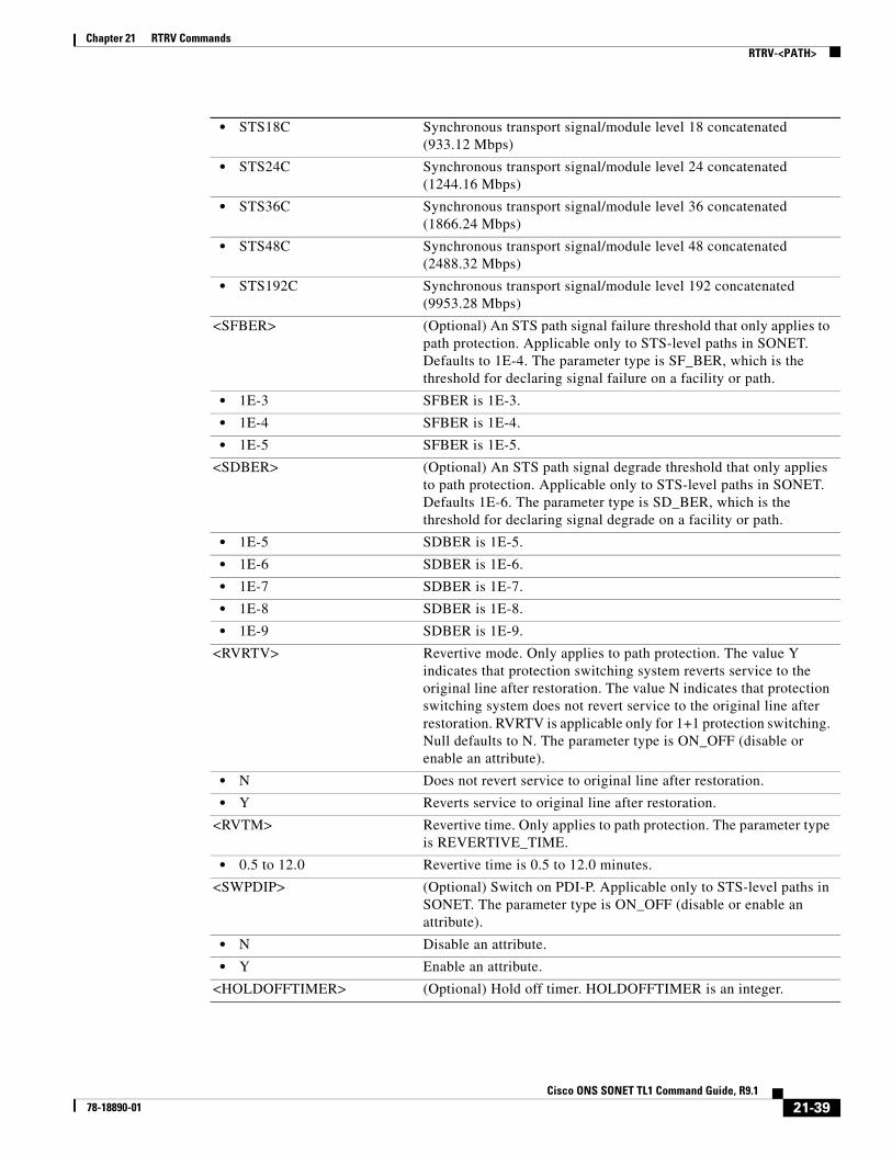
• STS18C Synchronous transport signal/module level 18 concatenated (933.12 Mbps)
• STS24C Synchronous transport signal/module level 24 concatenated (1244.16 Mbps)
• STS36C Synchronous transport signal/module level 36 concatenated (1866.24 Mbps)
• STS48C Synchronous transport signal/module level 48 concatenated (2488.32 Mbps)
• STS192C Synchronous transport signal/module level 192 concatenated (9953.28 Mbps)
<SFBER> (Optional) An STS path signal failure threshold that only applies to path protection. Applicable only to STS-level paths in SONET. Defaults to 1E-4. The parameter type is SF_BER, which is the threshold for declaring signal failure on a facility or path.
• 1E-3 SFBER is 1E-3.
• 1E-4 SFBER is 1E-4.
• 1E-5 SFBER is 1E-5.
<SDBER> (Optional) An STS path signal degrade threshold that only applies to path protection. Applicable only to STS-level paths in SONET. Defaults 1E-6. The parameter type is SD_BER, which is the threshold for declaring signal degrade on a facility or path.
• 1E-5 SDBER is 1E-5.
• 1E-6 SDBER is 1E-6.
• 1E-7 SDBER is 1E-7.
• 1E-8 SDBER is 1E-8.
• 1E-9 SDBER is 1E-9.
<RVRTV> Revertive mode. Only applies to path protection. The value Y indicates that protection switching system reverts service to the original line after restoration. The value N indicates that protection switching system does not revert service to the original line after restoration. RVRTV is applicable only for 1+1 protection switching. Null defaults to N. The parameter type is ON_OFF (disable or enable an attribute).
• N Does not revert service to original line after restoration.
• Y Reverts service to original line after restoration.
<RVTM> Revertive time. Only applies to path protection. The parameter type is REVERTIVE_TIME.
• 0.5 to 12.0 Revertive time is 0.5 to 12.0 minutes.
<SWPDIP> (Optional) Switch on PDI-P. Applicable only to STS-level paths in SONET. The parameter type is ON_OFF (disable or enable an attribute).
• N Disable an attribute.
• Y Enable an attribute.
<HOLDOFFTIMER> (Optional) Hold off timer. HOLDOFFTIMER is an integer.
21-39Cisco ONS SONET TL1 Command Guide, R9.1
78-18890-01

Chapter 21 RTRV CommandsRTRV-<PATH>
<EXPTRC> (Optional) Expected path trace content. Indicates the expected path trace message (J1) contents. EXPTRC is any 64-character ASCII string, including the terminating CR (carriage return) and LF (line feed). Applicable to STS-level paths in SONET. Defaults to NULL when a path protection path is created. Supported on the CE-100T-8 card (ONS 15310-CL) provisioned in mapper mode. EXPTRC is a string.
<TRC> (Optional) The path trace message to be transmitted. The trace byte (J1) continuously transmits a 64-byte, fixed length ASCII string, one byte at a time. A null value defaults to the NE transmitting 62 null characters (hex 00) and CR and LF. A null value defaults to the NE transmitting null characters (Hex 00). Applicable to STS-level paths in SONET. Applicable to VT-level paths for the DS3XM-12 card on the ONS 15454. Supported on the CE-100T-8 card (ONS 15310-CL) provisioned in mapper mode. TRC is a string.
<INCTRC> (Optional) The incoming path trace message contents. INCTRC is any combination of 64 characters. Applicable only to STS-level paths in SONET (STSn). Defaults to null when a path protection path is created. Supported on the CE-100T-8 card (ONS 15310-CL) provisioned in mapper mode. INCTRC is a string.
<TRCMODE> (Optional) Path trace mode. Applicable only to STS-level paths in SONET (STSn). Defaults to OFF when a path protection path is created. Supported on the CE-100T-8 card (ONS 15310-CL) provisioned in mapper mode. The parameter type is TRCMODE (trace mode).
• AUTO Use the previously received path trace string as the expected string (not applicable to MXP_2.5G_10G and TXP_MR_10G cards).
• AUTO-NO-AIS Use the previously received path trace string as the expected string and do not turn on AIS and RDI if TIM-P detected.
• MAN Use the provisioned expected string as the expected string.
• MAN-NO-AIS Use the provisioned expected string as the expected string and do not turn on AIS and RDI if TIM-P detected.
• OFF Turn off path trace capability. Nothing will be reported.
<TRCFORMAT> (Optional) Trace message size. The parameter type is TRCFORMAT (trace format).
• 1-BYTE 1-byte trace message
• 16-BYTE 16-byte trace message
• 64-BYTE 64-byte trace message
• Y Enable an attribute.
<TACC> (Optional) Test access. Indicates whether the digroup being provisioned is to be used as a test access digroup. Defaults to N. Not applicable to the ONS 15310-CL.
<TAPTYPE> (Optional) TAP type. Not applicable to the ONS 15310-CL. The parameter type is TAPTYPE, which is the test access point type
• DUAL Dual FAD
• SINGLE Single FAD
21-40Cisco ONS SONET TL1 Command Guide, R9.1
78-18890-01

Chapter 21 RTRV CommandsRTRV-<PATH>
<UPSRPTHSTATE> (Optional) Indicates whether a given AID is the working or standby path of a path protection cross-connect. The parameter type is STATUS, which is the status of the unit in the protection pair.
• ACT The entity is the active unit in the shelf.
• NA Status is unavailable.
• STBY The entity is the standby unit in the shelf.
<C2> (Optional) The C2 byte hex code. Applicable only to STS-level paths in SONET (STSn). The parameter type is C2_BYTE, which is the C2 byte hex code.
• 0X00 Unequipped
• 0X01 Equipped Non-Specific payload
• 0X02 VT-Structured STS-1 synchronous payload envelope (SPE)
• 0X03 Locked VT Mode
• 0X04 Asynchronous Mapping for DS3
• 0X12 Asynchronous Mapping for DS4 North American (NA)
• 0X13 Mapping for ATM
• 0X14 Mapping for DQDB
• 0X15 Asynchronous Mapping for FDDI
• 0X16 HDLC-Over-SONET Mapping
• 0XE1 VT-structured STS-1 SPE with 1VTx payload defect
• 0XE2 VT-structured STS-1 SPE with 2VTx payload defects
• 0XE3 VT-structured STS-1 SPE with 3VTx payload defects
• 0XE4 VT-structured STS-1 SPE with 4VTx payload defects
• 0XE5 VT-structured STS-1 SPE with 5VTx payload defects
• 0XE6 VT-structured STS-1 SPE with 6VTx payload defects
• 0XE7 VT-structured STS-1 SPE with 7VTx payload defects
• 0XE8 VT-structured STS-1 SPE with 8VTx payload defects
• 0XE9 VT-structured STS-1 SPE with 9VTx payload defects
• 0XEA VT-structured STS-1 SPE with 10VTx payload defects
• 0XEB VT-structured STS-1 SPE with 11VTx payload defects
• 0XEC VT-structured STS-1 SPE with 12VTx payload defects
• 0XED VT-structured STS-1 SPE with 13VTx payload defects
• 0XEE VT-structured STS-1 SPE with 14VTx payload defects
• 0XEF VT-structured STS-1 SPE with 15VTx payload defects
• 0XF0 VT-structured STS-1 SPE with 16VTx payload defects
• 0XF1 VT-structured STS-1 SPE with 17VTx payload defects
• 0XF2 VT-structured STS-1 SPE with 18VTx payload defects
• 0XF3 VT-structured STS-1 SPE with 19VTx payload defects
• 0XF4 VT-structured STS-1 SPE with 20VTx payload defects
• 0XF5 VT-structured STS-1 SPE with 21VTx payload defects
• 0XF6 VT-structured STS-1 SPE with 22VTx payload defects
• 0XF7 VT-structured STS-1 SPE with 23VTx payload defects
21-41Cisco ONS SONET TL1 Command Guide, R9.1
78-18890-01

Chapter 21 RTRV CommandsRTRV-<PATH>
• 0XF8 VT-structured STS-1 SPE with 24VTx payload defects
• 0XF9 VT-structured STS-1 SPE with 25VTx payload defects
• 0XFA VT-structured STS-1 SPE with 26VTx payload defects
• 0XFB VT-structured STS-1 SPE with 27VTx payload defects
• 0XFC VT-structured STS-1 SPE with 28VTx payload defects
• 0XFE O.181 Test Signal (TSS1 to TSS3) Mapping
• 0XFF Reserved, however, C2 is 0XFF if an AIS-L is being generated by an optical card or cross-connect downstream.
<BLSRPTHSTATE> (Optional) The BLSR path state only if the port is on the BLSR. Applicable only to STS-level paths in SONET (STSn). The parameter type is BLSR_PTH_STATE, which is the BLSR path state only if the port is on the BLSR.
• PCAPTHACT Indicates the BLSR is not switched and its PCA path is in the active state.
• PCAPTHSTB Indicates the BLSR is switched and its PCA path is in the standby state.
• PROTPTHACT Indicates the BLSR is switched and its protection path is in the active state.
• WKGPTHACT Indicates the BLSR is not switched and its working path is in the active state.
• WKGPTHSTB Indicates the BLSR is switched and its working path is in the standby state.
<PST_PSTQ> Administrative state in the PST_PSTQ format. The parameter type is PST_PSTQ, which is the service state of the entity described by the PST and PSTQ.
• IS-NR In Service and Normal
• OOS-AU Out of Service and Autonomous
• OOS-AUMA Out of Service and Autonomous Management
• OOS-MA Out of Service and Management
<SSTQ> (Optional) Secondary state of the entity. The parameter type is SST, which provides additional information pertaining to PST and PSTQ.
• AINS Automatic In-Service
• DSBLD Disabled
• LPBK Loopback
• MEA Mismatch of Equipment
• MT Maintenance
• OOG Out of Group
• SWDL Software Download
• UAS Unassigned
• UEQ Unequipped
21-42Cisco ONS SONET TL1 Command Guide, R9.1
78-18890-01

Chapter 21 RTRV CommandsRTRV-10GIGE
21.7 RTRV-10GIGE(Cisco ONS 15454) The Retrieve 10GIGE (RTRV-10GIGE) command retrieves the 10 Gbps-specific parameters for a port that has been configured to support the Gigabit Ethernet payload with the ENT-10GIGE command.
Usage Guidelines None
Category Ports
Security Retrieve
Input Format RTRV-10GIGE:[<TID>]:<AID>:<CTAG>[::::];
Input Example RTRV-10GIGE:TID:FAC-1-1:100;
Input Parameters
Output Format SID DATE TIMEM CTAG COMPLD “<AID>:,,[<ROLE>],[<STATUS>]:[NAME=<NAME>],[MACADDR=<MACADDR>], [LBCL=<LBCL>],[OPT=<OPT>],[OPR=<OPR>],[FREQ=<FREQ>], [LOSSB=<LOSSB>]:<PSTPSTQ>,[<SST>]”;
Output Example TID-000 1998-06-20 14:30:00M 001 COMPLD “FAC-6-1:,,WORK,ACT:NAME=\"NY PORT\",MACADDR=00-0E-AA-BB-CC-FF,LBCL=10.0, OPT=10.0,OPR=10.0,FREQ=1550,LOSSB=SX:OOS-AU,AINS”;
Output Parameters
<AID> Access identifier from the “26.15 FACILITY” section on page 35.
<AID> Access identifier from the “26.15 FACILITY” section on page 35.
<ROLE> (Optional) The port role in Y-cable protection (WORK or PROT). The parameter type is SIDE, which is the role the unit is playing in the protection group.
• PROT The entity is a protection unit in the protection group.
• WORK The entity is a working unit in the protection group.
21-43Cisco ONS SONET TL1 Command Guide, R9.1
78-18890-01

Chapter 21 RTRV CommandsRTRV-10GIGE
<STATUS> (Optional) A port status in Y-cable protection (ACT or STBY). The parameter type is STATUS, which is the status of the unit in the protection pair.
• ACT The entity is the active unit in the shelf.
• NA Status is unavailable.
• STBY The entity is the standby unit in the shelf.
<NAME> (Optional) Port name. NAME is a string.
<MACADDR> (Optional) The MAC address for the 10-Gigabit Ethernet payload. MACADDR is a string.
<LBCL> (Optional) Displays the current value of the laser current. LBCL is a float.
<OPT> (Optional) Displays the current value of the transmitted optical power. OPT is a float.
<OPR> (Optional) Displays the current value of the received optical power. OPR is a float.
<FREQ> (Optional) Parameter type is OPTICAL_WLEN (optical wavelength).
• 1310 Wavelength 1310
• 1470 Wavelength 1470
• 1490 Wavelength 1490
• 1510 Wavelength 1510
• 1529.55 Wavelength 1529.55
• 1529.94 Wavelength 1529.94
• 1530 Wavelength 1530
• 1530.33 Wavelength 1530.33
• 1530.73 Wavelength 1530.73
• 1531.12 Wavelength 1531.12
• 1531.51 Wavelength 1531.51
• 1531.90 Wavelength 1531.90
• 1532.29 Wavelength 1532.29
• 1532.68 Wavelength 1532.68
• 1533.07 Wavelength 1533.07
• 1533.47 Wavelength 1533.47
• 1533.86 Wavelength 1533.86
• 1534.25 Wavelength 1534.25
• 1534.64 Wavelength 1534.64
• 1535.04 Wavelength 1535.04
• 1535.43 Wavelength 1535.43
• 1535.82 Wavelength 1535.82
• 1536.22 Wavelength 1536.22
• 1536.61 Wavelength 1536.61
• 1537 Wavelength 1537
• 1537.40 Wavelength 1537.40
21-44Cisco ONS SONET TL1 Command Guide, R9.1
78-18890-01

Chapter 21 RTRV CommandsRTRV-10GIGE
• 1537.79 Wavelength 1537.79
• 1538.19 Wavelength 1538.19
• 1538.58 Wavelength 1538.58
• 1538.98 Wavelength 1538.98
• 1539.37 Wavelength 1539.37
• 1539.77 Wavelength 1539.77
• 1540.16 Wavelength 1540.16
• 1540.56 Wavelength 1540.56
• 1540.95 Wavelength 1540.95
• 1541.35 Wavelength 1541.35
• 1541.75 Wavelength 1541.75
• 1542.14 Wavelength 1542.14
• 1542.35 Wavelength 1542.35
• 1542.54 Wavelength 1542.54
• 1542.94 Wavelength 1542.94
• 1543.33 Wavelength 1543.33
• 1543.73 Wavelength 1543.73
• 1544.13 Wavelength 1544.13
• 1544.53 Wavelength 1544.53
• 1544.92 Wavelength 1544.92
• 1545.32 Wavelength 1545.32
• 1545.72 Wavelength 1545.72
• 1546.12 Wavelength 1546.12
• 1546.52 Wavelength 1546.52
• 1546.92 Wavelength 1546.92
• 1547.32 Wavelength 1547.32
• 1547.72 Wavelength 1547.72
• 1548.12 Wavelength 1548.12
• 1548.51 Wavelength 1548.51
• 1548.92 Wavelength 1548.92
• 1549.32 Wavelength 1549.32
• 1549.71 Wavelength 1549.71
• 1550 Wavelength 1500
• 1550.12 Wavelength 1550.12
• 1550.52 Wavelength 1550.52
• 1550.92 Wavelength 1550.92
• 1551.32 Wavelength 1551.32
• 1551.72 Wavelength 1551.72
• 1552.12 Wavelength 1552.12
• 1552.52 Wavelength 1552.52
• 1552.93 Wavelength 1552.93
21-45Cisco ONS SONET TL1 Command Guide, R9.1
78-18890-01

Chapter 21 RTRV CommandsRTRV-10GIGE
• 1553.33 Wavelength 1553.33
• 1553.73 Wavelength 1553.73
• 1554.13 Wavelength 1554.13
• 1554.13 Wavelength 1554.13
• 1554.94 Wavelength 1554.94
• 1555.34 Wavelength 1555.34
• 1555.75 Wavelength 1555.75
• 1556.15 Wavelength 1556.15
• 1556.55 Wavelength 1556.55
• 1556.96 Wavelength 1556.96
• 1557.36 Wavelength 1557.36
• 1557.77 Wavelength 1557.77
• 1558.17 Wavelength 1558.17
• 1558.58 Wavelength 1558.58
• 1558.98 Wavelength 1558.98
• 1559.39 Wavelength 1559.39
• 1559.79 Wavelength 1559.79
• 1560.20 Wavelength 1560.20
• 1560.61 Wavelength 1560.61
• 1561.01 Wavelength 1561.01
• 1561.42 Wavelength 1561.42
• 1561.83 Wavelength 1561.83
• 1570 Wavelength 1570
• 1570.83 Wavelength 1570.83
• 1571.24 Wavelength 1571.24
• 1571.65 Wavelength 1571.65
• 1572.06 Wavelength 1572.06
• 1572.48 Wavelength 1572.48
• 1572.89 Wavelength 1572.89
• 1573.30 Wavelength 1573.30
• 1573.71 Wavelength 1573.71
• 1574.13 Wavelength 1574.13
• 1574.54 Wavelength 1574.54
• 1574.95 Wavelength 1574.95
• 1575.37 Wavelength 1575.37
• 1575.78 Wavelength 1575.78
• 1576.20 Wavelength 1576.20
• 1576.61 Wavelength 1576.61
• 1577.03 Wavelength 1577.03
• 1577.44 Wavelength 1577.44
• 1577.86 Wavelength 1577.86
21-46Cisco ONS SONET TL1 Command Guide, R9.1
78-18890-01

Chapter 21 RTRV CommandsRTRV-10GIGE
• 1578.27 Wavelength 1578.27
• 1578.69 Wavelength 1578.69
• 1579.10 Wavelength 1579.10
• 1579.52 Wavelength 1579.52
• 1579.93 Wavelength 1579.93
• 1580.35 Wavelength 1580.35
• 1580.77 Wavelength 1580.77
• 1581.18 Wavelength 1581.18
• 1581.60 Wavelength 1581.60
• 1582.02 Wavelength 1582.02
• 1582.44 Wavelength 1582.44
• 1582.85 Wavelength 1582.85
• 1583.27 Wavelength 1583.27
• 1583.69 Wavelength 1583.69
• 1584.11 Wavelength 1584.11
• 1584.53 Wavelength 1584.53
• 1584.95 Wavelength 1584.95
• 1585.36 Wavelength 1585.36
• 1585.78 Wavelength 1585.78
• 1586.20 Wavelength 1586.20
• 1586.62 Wavelength 1586.62
• 1587.04 Wavelength 1587.04
• 1587.46 Wavelength 1587.46
• 1587.88 Wavelength 1587.88
• 1588.30 Wavelength 1588.30
• 1588.73 Wavelength 1588.73
• 1589.15 Wavelength 1589.15
• 1589.57 Wavelength 1589.57
• 1589.99 Wavelength 1589.99
• 1590 Wavelength 1590
• 1590.41 Wavelength 1590.41
• 1590.83 Wavelength 1590.83
• 1591.26 Wavelength 1591.26
• 1591.68 Wavelength 1591.68
• 1592.10 Wavelength 1592.10
• 1592.52 Wavelength 1592.52
• 1592.95 Wavelength 1592.95
• 1593.37 Wavelength 1593.37
• 1593.79 Wavelength 1593.79
• 1594.22 Wavelength 1594.22
• 1594.64 Wavelength 1594.64
21-47Cisco ONS SONET TL1 Command Guide, R9.1
78-18890-01

Chapter 21 RTRV CommandsRTRV-10GIGE
• 1595.06 Wavelength 1595.06
• 1595.49 Wavelength 1595.49
• 1596.34 Wavelength 1596.34
• 1596.76 Wavelength 1596.76
• 1597.19 Wavelength 1597.19
• 1597.62 Wavelength 1597.62
• 1598.04 Wavelength 1598.04
• 1598.47 Wavelength 1598.47
• 1598.89 Wavelength 1598.89
• 1599.32 Wavelength 1599.32
• 1599.75 Wavelength 1599.75
• 1600.06 Wavelength 1600.06
• 1601.03 Wavelength 1601.03
• 1601.46 Wavelength 1601.46
• 1601.88 Wavelength 1601.88
• 1602.31 Wavelength 1602.31
• 1602.74 Wavelength 1602.74
• 1603.17 Wavelength 1603.17
• 1603.60 Wavelength 1603.60
• 1604.03 Wavelength 1604.03
• 1610 Wavelength 1610
• USE-TWL1 Use Tunable Wavelength 1
<LOSSB> (Optional) The parameter type is REACH (reach values).
• AUTOPROV Autoprovisioning
• CX Reach CX
• DX Reach DX
• HX Reach HX
• I1 Reach I1
• IR-1 Reach IR-1
• IR-2 Reach IR-2
• L1 Reach L1
• L2 Reach L2
• L3 Reach L3
• LR-1 Reach LR-1
• LR-2 Reach LR-2
• LR-3 Reach LR-3
• LX Reach LX
• S1 Reach S1
• S2 Reach S2
• SR Reach SR
• SR-1 Reach SR-1
21-48Cisco ONS SONET TL1 Command Guide, R9.1
78-18890-01

Chapter 21 RTRV CommandsRTRV-ALM-<MOD2ALM>
21.8 RTRV-ALM-<MOD2ALM>(Cisco ONS 15454, 15327, 15600, 15310) The Retrieve Alarm for (10GFC, 10GIGE, 40GIGE, 1GFC, 1GFICON, 2GFC, 2GFICON, 4GFC, 4GFICON, 5GIB, 8GFC, DS1, DS3I, DVBASI, E1, E100, E1000, E3, E4, EC1, ETH, FSTE, G1000, GFPOS, GIGE, ILK, ISCCOMPAT, ISC1, ISC3PEER2R, ISC3PEER1G, ISC3PEER2G, OC12, OC192, OC3, OC48, OC768, OCH, OMS, OTS, OTU2, OTU3, POS, RPRIF, STM1, STM4, STM16, STM64, STM1E, STS1, STS12C, STS18C, STS192C, STS24C, STS36C, STS3C, STS48C, STS96C, STS6C, STS9C, T1, T3, UDCDCC, UDCF, VC3,VC4,VC4-2c,VC4-3c,VC4-4c,VC4-16c,VC4-64c, VC11, VC12, VC3, VCG, VT1, VT2, or WLEN (RTRV-ALM-<MOD2ALM>) command retrieves and sends the current status of alarm conditions. The alarm condition or severity to be retrieved can be specified by using the input parameters as a filter.
Usage Guidelines See Table 28-1 on page 1 for supported modifiers by platform.
Note VT1-n-n-n replaces PS_VT1-n-n-n for the VT1 alarm AID.
Note The AIDTYPE shows STS1 for STS alarms.
• SX Reach SX
• T Reach T
• VX Reach VX
• ZX Reach ZX
<PST_PSTQ> Administrative state in the PST_PSTQ format. The parameter type is PST_PSTQ, which is the service state of the entity described by the SST and PSTQ.
• IS-NR In Service and Normal
• OOS-AU Out of Service and Autonomous
• OOS-AUMA Out of Service and Autonomous Management
• OOS-MA Out of Service and Management
<SSTQ> (Optional) Secondary state of the entity. The parameter type is SST, which provides additional information pertaining to PST and PSTQ.
• AINS Automatic In-Service
• DSBLD Disabled
• LPBK Loopback
• MEA Mismatch of Equipment
• MT Maintenance
• OOG Out of Group
• SWDL Software Download
• UAS Unassigned
• UEQ Unequipped
21-49Cisco ONS SONET TL1 Command Guide, R9.1
78-18890-01

Chapter 21 RTRV CommandsRTRV-ALM-<MOD2ALM>
Category Fault
Security Retrieve
Input Format RTRV-ALM-<MOD2ALM>:[<TID>]:<AID>:<CTAG>::[<NTFCNCDE>],[<CONDTYPE>],[<SRVEFF>][<LOCN>],[<DIRN>][,];
Input Example RTRV-ALM-OC12:ELDRIDGE:FAC-5-1:225::MN,SD,SA,NEND,RCV;
Input Parameters <AID> Access identifier from the “26.2 AidUnionId” section on page 12.
<NTFCNCDE> Two-letter notification code. A null value is equivalent to ALL. The parameter type is NOTIF_CODE, which is the two-character notification code associated with an autonomous message.
• CL The condition causing the alarm has cleared.
• CR A critical alarm.
• MJ A major alarm.
• MN A minor alarm.
• NA The condition is not alarmed.
• NR The alarm is not reported.
<CONDTYPE> Condition type for an alarm or a reported event. The parameter type is CONDITION, which is any problem detected on an ONS 15454, ONS 15310-CL, ONS 15310-MA, or ONS 15600 shelf, whether or not the problem is reported (that is, whether or not it generates a trouble notification). Reported conditions include alarms, NA conditions, and NR conditions. See Chapter 27, “Conditions” for a list of conditions.
<SRVEFF> The effect on service caused by the standing alarm or condition. The parameter type is SERV_EFF, which is the effect of the alarm on service. A null value is equivalent to ALL.
• NSA The condition is non-service affecting.
• SA The condition is service affecting.
<LOCN> Location associated with a particular command. Identifies the location from which the PM mode is to be retrieved. The parameter type is LOCATION, which is the location where the action is to take place.
• FEND Action occurs on the far end of the facility.
• NEND Action occurs on the near end of the facility.
<DIRN> The PM count retrieval direction. The parameter type is DIRECTION, which is the transmit and receive directions.
• BTH Both transmit and receive directions
• RCV Receive direction only
21-50Cisco ONS SONET TL1 Command Guide, R9.1
78-18890-01

Chapter 21 RTRV CommandsRTRV-ALM-<MOD2ALM>
Output Format SID DATE TIMEM CTAG COMPLD “<AID>,[<AIDTYPE>]:<NTFCNCDE>,<CONDTYPE>,<SRVEFF>,[<OCRDAT>], [<OCRTM>],[<LOCN>],[<DIRN>]:[<DESC>]”
;
Output Example TID-000 1998-06-20 14:30:00M 001 COMPLD “FAC-5-1,OC12:MJ,SD,SA,09-05,12-30-20,NEND,RCV:\"BER AT SIGNAL DEGRADE LEVEL\",";
Output Parameters <AID> Access identifier from the “26.1 ALL” section on page 1.
<AIDTYPE> (Optional) Type of access identifier. The parameter type is MOD2ALM (alarm type).
• 1GFC 1-Gigabit Fibre Channel payload
• 1GFICON 1-Gigabit fiber connectivity payload
• 1GISC3 1-Gigabit ISC3 compatible
• 2GFC 2-Gigabit Fibre Channel payload
• 2GFICON 2-Gigabit fiber connectivity payload
• 4GFC 4-Gigabit Fibre Channel payload
• 4GFICON 4-Gigabit fiber connectivity payload
• 40GIGE 40-Gigabit Ethernet
• 5GIB 5Gbps InfiniBand payload
• 8GFC 8-Gigabit Fibre Channel payload
• CLNT Client facility for MXP/TXP cards
• DS1 DS1 alarm
• DS3I DS3I alarm
• DVBASI Digital Video Broadband Asynchronous Serial Interface (DVBASI) payload
• E100 E100 alarm
• E1000 E1000 alarm
• EC1 EC1 alarm
• FSTE Fast Ethernet Port alarm
• G1000 G1000 alarm
• GFPOS Generic framing protocol over packet over SONET virtual port alarm
• GIGE Gigabit Ethernet port alarm
• ISC1 InterSystem Channel, a protocol defined by IBM (ISC1) payload
• ISC3PEER1G 1-Gigabit ISC3 Peer
• ISC3PEER2G 2-Gigabit ISC3 Peer
• ISC3PEER2R 1-Gigabit or 2-Gigabit ISC3 peer used in transparent (2R) mode
• ISCCOMPAT 1-Gigabit ISC1, ISC2, and ISC3 compatibility
21-51Cisco ONS SONET TL1 Command Guide, R9.1
78-18890-01

Chapter 21 RTRV CommandsRTRV-ALM-<MOD2ALM>
• ML1000-2 (ONS 15454) ML-Series two port Gigabit Ethernet card
• OC3 OC3 alarm
• OC12 OC12 alarm
• OC48 OC48 alarm
• OC192 OC192 alarm
• OC768 OC768 alarm
• OCH Optical channel
• OCHTERM OCH termination
• OMS Optical Multiplex Section
• OTS Optical Transport Section
• OTU3 Optical Transport Unit Level 3
• POS POS port alarm
• STS1 STS1 alarm
• STS3C STS3c alarm
• STS6C STS6c alarm
• STS9C STS9c alarm
• STS18C STS18c alarm
• STS12C STS12c alarm
• STS24C STS24c alarm
• STS36C STS36c alarm
• STS48C STS48c alarm
• STS192C STS192c alarm
• T1 T1 alarm
• T3 T3 alarm
• UDCDCC UDC-DCC alarm
• UDCF UCD-F alarm
• VCG Virtual concatenation group alarm
• VT1 VT1 alarm
• VT2 VT2 alarm
• WLEN Wavelength path provisioning
<NTFCNCDE> Two-letter notification code. The parameter type is NOTIF_CODE, which is the two-character notification code associated with an autonomous message.
• CL The condition causing the alarm has cleared.
• CR A critical alarm.
• MJ A major alarm.
• MN A minor alarm.
• NA The condition is not alarmed.
• NR The alarm is not reported.
21-52Cisco ONS SONET TL1 Command Guide, R9.1
78-18890-01

Chapter 21 RTRV CommandsRTRV-ALMTYPE
21.9 RTRV-ALMTYPE(Cisco ONS 15310-CL, Cisco ONS 15310-MA, Cisco ONS 15454, and Cisco ONS 15600) The Retrieve Alarm Type command retrieves all system and user-defined alarm types.
Usage Guidelines None
Category System
Security Retrieve
Input Format RTRV-ALMTYPE:[<TID>]::<CTAG>;
<CONDTYPE> Condition type for an alarm or a reported event. The parameter type is CONDITION, which is any problem detected on an ONS 15454, ONS 15310-CL, ONS 15310-MA, or ONS 15600 shelf, whether or not the problem is reported (that is, whether or not it generates a trouble notification). Reported conditions include alarms, NA conditions, and NR conditions. See Chapter 27, “Conditions” for a list of conditions.
<SRVEFF> The effect on service caused by the standing alarm or condition. The parameter type is SERV_EFF, which is the effect of the alarm on service.
• NSA The condition is non-service affecting.
• SA The condition is service affecting.
<OCRDAT> (Optional) Date when the specific event or violation occurred, MM-DD.
<OCRTM> (Optional) Time when the specific event or violation occurred, HH-MM-SS.
<LOCN> Location associated with a particular command in reference to the entity identified by the AID. A null value defaults to NEND. The parameter type is LOCATION, which is the location where the action is to take place.
• FEND Action occurs on the far end of the facility.
• NEND Action occurs on the near end of the facility.
<DIRN> The PM count retrieval direction. The parameter type is DIRECTION, which is the transmit and receive directions.
• BTH Both transmit and receive directions
• RCV Receive direction only
<DESC> (Optional) A condition description. DESC is a string.
21-53Cisco ONS SONET TL1 Command Guide, R9.1
78-18890-01
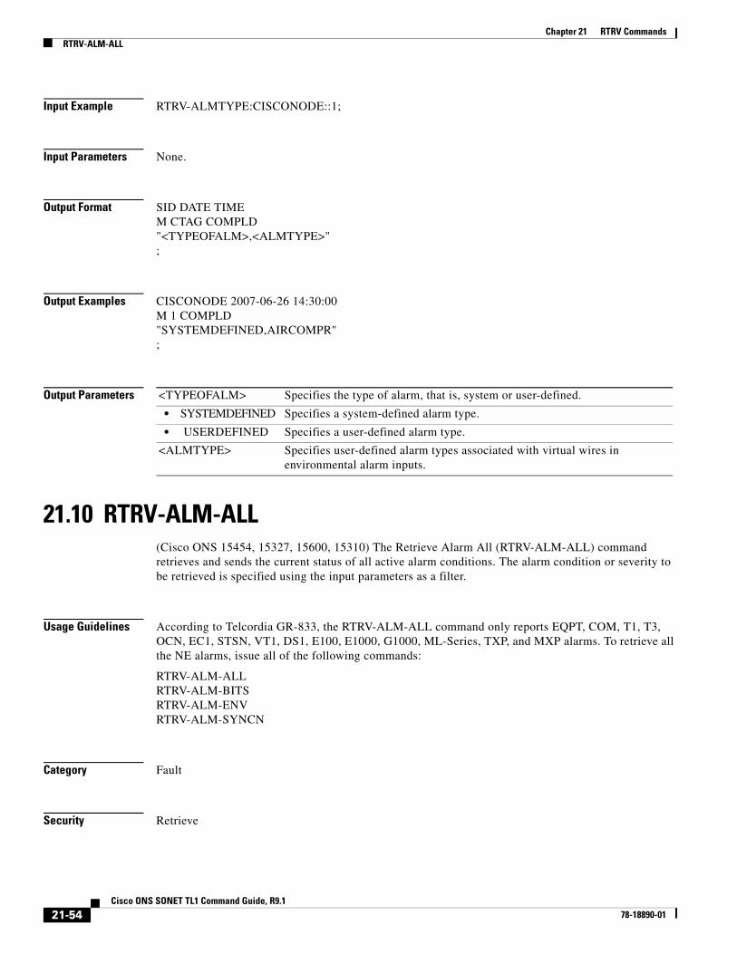
Chapter 21 RTRV CommandsRTRV-ALM-ALL
Input Example RTRV-ALMTYPE:CISCONODE::1;
Input Parameters None.
Output Format SID DATE TIMEM CTAG COMPLD"<TYPEOFALM>,<ALMTYPE>";
Output Examples CISCONODE 2007-06-26 14:30:00M 1 COMPLD"SYSTEMDEFINED,AIRCOMPR";
Output Parameters
21.10 RTRV-ALM-ALL(Cisco ONS 15454, 15327, 15600, 15310) The Retrieve Alarm All (RTRV-ALM-ALL) command retrieves and sends the current status of all active alarm conditions. The alarm condition or severity to be retrieved is specified using the input parameters as a filter.
Usage Guidelines According to Telcordia GR-833, the RTRV-ALM-ALL command only reports EQPT, COM, T1, T3, OCN, EC1, STSN, VT1, DS1, E100, E1000, G1000, ML-Series, TXP, and MXP alarms. To retrieve all the NE alarms, issue all of the following commands:
RTRV-ALM-ALLRTRV-ALM-BITSRTRV-ALM-ENVRTRV-ALM-SYNCN
Category Fault
Security Retrieve
<TYPEOFALM> Specifies the type of alarm, that is, system or user-defined.
• SYSTEMDEFINED Specifies a system-defined alarm type.
• USERDEFINED Specifies a user-defined alarm type.
<ALMTYPE> Specifies user-defined alarm types associated with virtual wires in environmental alarm inputs.
21-54Cisco ONS SONET TL1 Command Guide, R9.1
78-18890-01

Chapter 21 RTRV CommandsRTRV-ALM-ALL
Input Format RTRV-ALM-ALL:[<TID>]:[<AID>]:<CTAG>::[<NTFCNCDE>],[<CONDITION>],[<SRVEFF>],[<LOCN>],[<DIRN>],[,];
Input Example RTRV-ALM-ALL:COTATI:ALL:229::MN,PWRRESTART,NSA,NEND,RCV;
Input Parameters
Output Format SID DATE TIMEM CTAG COMPLD “[<AID>],[<AIDTYPE>]:<NTFCNCDE>,<CONDTYPE>,<SRVEFF>,[<LOCN>],[<DIRN>]:[<DESC>],[<AIDDET>]”
;
<AID> Access identifier from the “26.1 ALL” section on page 1. A null value is equivalent to ALL. AID is a string.
<NTFCNCDE> Two-letter notification code. A null value is equivalent to ALL. The parameter type is NOTIF_CODE, which is the two-character notification code associated with an autonomous message.
• CR A critical alarm.
• MJ A major alarm.
• MN A minor alarm.
<CONDITION> The type of alarm condition. A null value is equivalent to ALL. The parameter type is CONDITION, which is any problem detected on an ONS 15454, ONS 15310-CL, ONS 15310-MA, or ONS 15600 shelf, whether or not the problem is reported (that is, whether or not it generates a trouble notification). Reported conditions include alarms, NA conditions, and NR conditions. See Chapter 27, “Conditions” for a list of conditions.
<SRVEFF> The effect on service caused by the standing alarm or condition. The parameter type is SERV_EFF, which is the effect of the alarm on service. A null value is equivalent to ALL.
• NSA The condition is non-service affecting.
• SA The condition is service affecting.
<LOCN> Location associated with a particular command. Identifies the location from which the PM mode is to be retrieved. The parameter type is LOCATION, which is the location where the action is to take place.
• FEND Action occurs on the far end of the facility.
• NEND Action occurs on the near end of the facility.
<DIRN> The PM count retrieval direction. The parameter type is DIRECTION, which is the transmit and receive directions.
• BTH Both transmit and receive directions
• RCV Receive direction only
21-55Cisco ONS SONET TL1 Command Guide, R9.1
78-18890-01
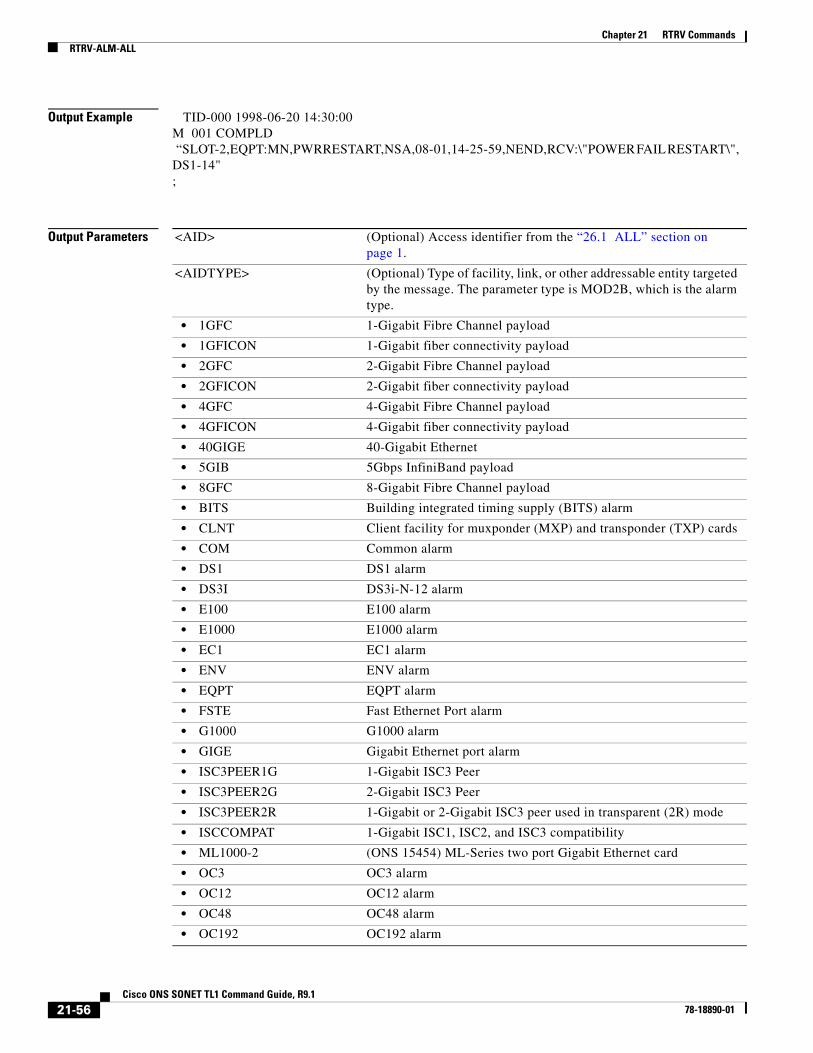
Chapter 21 RTRV CommandsRTRV-ALM-ALL
Output Example TID-000 1998-06-20 14:30:00M 001 COMPLD “SLOT-2,EQPT:MN,PWRRESTART,NSA,08-01,14-25-59,NEND,RCV:\"POWER FAIL RESTART\", DS1-14";
Output Parameters <AID> (Optional) Access identifier from the “26.1 ALL” section on page 1.
<AIDTYPE> (Optional) Type of facility, link, or other addressable entity targeted by the message. The parameter type is MOD2B, which is the alarm type.
• 1GFC 1-Gigabit Fibre Channel payload
• 1GFICON 1-Gigabit fiber connectivity payload
• 2GFC 2-Gigabit Fibre Channel payload
• 2GFICON 2-Gigabit fiber connectivity payload
• 4GFC 4-Gigabit Fibre Channel payload
• 4GFICON 4-Gigabit fiber connectivity payload
• 40GIGE 40-Gigabit Ethernet
• 5GIB 5Gbps InfiniBand payload
• 8GFC 8-Gigabit Fibre Channel payload
• BITS Building integrated timing supply (BITS) alarm
• CLNT Client facility for muxponder (MXP) and transponder (TXP) cards
• COM Common alarm
• DS1 DS1 alarm
• DS3I DS3i-N-12 alarm
• E100 E100 alarm
• E1000 E1000 alarm
• EC1 EC1 alarm
• ENV ENV alarm
• EQPT EQPT alarm
• FSTE Fast Ethernet Port alarm
• G1000 G1000 alarm
• GIGE Gigabit Ethernet port alarm
• ISC3PEER1G 1-Gigabit ISC3 Peer
• ISC3PEER2G 2-Gigabit ISC3 Peer
• ISC3PEER2R 1-Gigabit or 2-Gigabit ISC3 peer used in transparent (2R) mode
• ISCCOMPAT 1-Gigabit ISC1, ISC2, and ISC3 compatibility
• ML1000-2 (ONS 15454) ML-Series two port Gigabit Ethernet card
• OC3 OC3 alarm
• OC12 OC12 alarm
• OC48 OC48 alarm
• OC192 OC192 alarm
21-56Cisco ONS SONET TL1 Command Guide, R9.1
78-18890-01

Chapter 21 RTRV CommandsRTRV-ALM-ALL
• OC768 OC768 alarm
• OCH Optical channel
• OMS Optical Multiplex Section
• OTS Optical Transport Section
• OTU3 Optical Transport Unit Level 3
• POS Packet over SONET (POS) port alarm
• STS1 STS1 alarm
• STS3C STS3c alarm
• STS6C STS6c alarm
• STS9C STS9c alarm
• STS18C STS18c alarm
• STS12C STS12c alarm
• STS24C STS24c alarm
• STS36C STS36c alarm
• STS48C STS48c alarm
• STS192C STS192c alarm
• SYNCN SYNCN alarm
• T1 T1 alarm
• T3 T3 alarm
• TCC TCC alarm
• VT1 VT1 alarm
• VT2 VT2 alarm
<NTFCNCDE> Two-letter notification code. The parameter type is NOTIF_CODE, which is the two-character notification code associated with an autonomous message.
• CL The condition causing the alarm has cleared.
• CR A critical alarm.
• MJ A major alarm.
• MN A minor alarm.
• NA The condition is not alarmed.
• NR The alarm is not reported.
<CONDTYPE> Condition type for an alarm or a reported event. The parameter type is CONDITION, which is any problem detected on an ONS 15454, ONS 15310-CL, ONS 15310-MA, or ONS 15600 shelf, whether or not the problem is reported (that is, whether or not it generates a trouble notification). Reported conditions include alarms, NA conditions, and NR conditions. See Chapter 27, “Conditions” for a list of conditions.
<SRVEFF> The effect on service caused by the standing alarm or condition. The parameter type is SERV_EFF, which is the effect of the alarm on service.
• NSA The condition is non-service affecting.
• SA The condition is service affecting.
21-57Cisco ONS SONET TL1 Command Guide, R9.1
78-18890-01

Chapter 21 RTRV CommandsRTRV-ALM-BITS
21.11 RTRV-ALM-BITS(Cisco ONS 15454, 15327, 15600, 15310) The Retrieve Alarm Building Integrated Timing Supply (RTRV-ALM-BITS) command retrieves and sends the current status of alarm conditions associated with the BITS facility. The alarm condition or severity retrieved is specified using the input parameters as a filter.
Usage Guidelines None
Category Synchronization
Security Retrieve
Input Format RTRV-ALM-BITS:[<TID>]:<AID>:<CTAG>::[<NTFCNCDE>],[<CONDTYPE>],[<SRVEFF>],[<LOCN>],[<DIRN>];
Input Example RTRV-ALM-BITS:ELVERANO:BITS-1:228::CR,LOS,SA;
<LOCN> Location associated with a particular command. Identifies the location from which the PM mode is to be retrieved. The parameter type is LOCATION, which is the location where the action is to take place.
• FEND Action occurs on the far end of the facility.
• NEND Action occurs on the near end of the facility.
<DIRN> The PM count retrieval direction. The parameter type is DIRECTION, which is the transmit and receive directions.
• BTH Both transmit and receive directions
• RCV Receive direction only
<OCRDAT> (Optional) Date when the specific event or violation occurred, MM-DD.
<OCRTM> (Optional) Time when the specific event or violation occurred, HH-MM-SS.
<DESC> (Optional) A condition description. DESC is a string.
<AIDDET> (Optional) AIDDET uses the same addressing rules as the AID, but specifies AID type and additional details about the entity being managed. The supplementary equipment identification.
21-58Cisco ONS SONET TL1 Command Guide, R9.1
78-18890-01

Chapter 21 RTRV CommandsRTRV-ALM-BITS
Input Parameters
Output Format SID DATE TIMEM CTAG COMPLD“<AID>,[<AIDTYPE>]:<NTFCNCDE>,<CONDTYPE>,<SRVEFF>, [<OCRDAT>],[<OCRTM>],[<LOCATION>],[<DIRECTION>],:[<DESC>]”
;
Output Example TID-000 1998-06-20 14:30:00M 001 COMPLD “BITS-1,BITS:CR,LOS,SA,,,,:\“LOSS OF SIGNAL\”,”;
<AID> Access identifier from the “26.6 BITS” section on page 19.
<NTFCNCDE> Two-letter notification code. A null value is equivalent to ALL. The parameter type is NOTIF_CODE, which is the two-character notification code associated with an autonomous message.
• CL The condition causing the alarm has cleared.
• CR A critical alarm.
• MJ A major alarm.
• MN A minor alarm.
• NA The condition is not alarmed.
• NR The alarm is not reported.
<CONDTYPE> The condition type for an alarm or reported event. A null value is equivalent to ALL. The parameter type is CONDITION, which is any problem detected on an ONS 15454, ONS 15310-CL, ONS 15310-MA or ONS 15600 shelf, whether or not the problem is reported (that is, whether or not it generates a trouble notification). Reported conditions include alarms, NA conditions, and NR conditions. See Chapter 27, “Conditions” for a list of conditions.
<SRVEFF> The effect on service caused by the standing alarm or condition. The parameter type is SERV_EFF, which is the effect of the alarm on service. A null value is equivalent to ALL.
• NSA The condition is non-service affecting.
• SA The condition is service affecting.
<LOCN> Location associated with a particular command. Identifies the location from which the PM mode is to be retrieved. The parameter type is LOCATION, which is the location where the action is to take place.
• FEND Action occurs on the far end of the facility.
• NEND Action occurs on the near end of the facility.
<DIRN> The PM count retrieval direction. The parameter type is DIRECTION, which is the transmit and receive directions.
• BTH Both transmit and receive directions
• RCV Receive direction only
21-59Cisco ONS SONET TL1 Command Guide, R9.1
78-18890-01
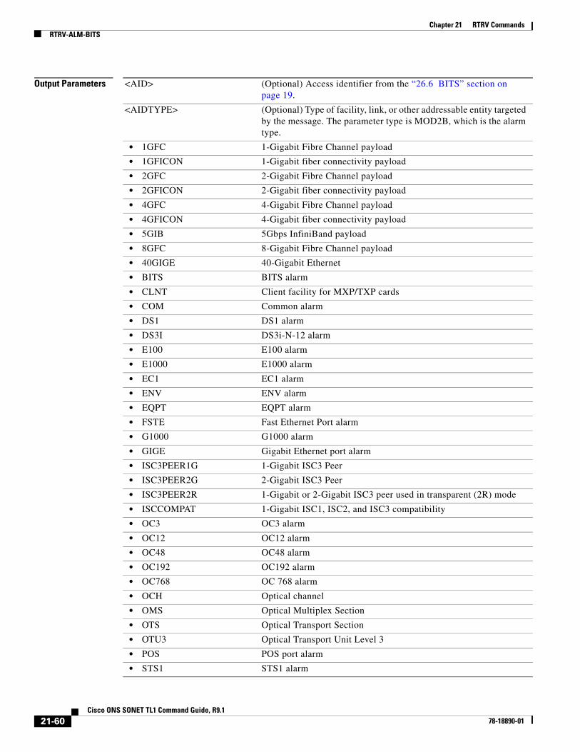
Chapter 21 RTRV CommandsRTRV-ALM-BITS
Output Parameters <AID> (Optional) Access identifier from the “26.6 BITS” section on page 19.
<AIDTYPE> (Optional) Type of facility, link, or other addressable entity targeted by the message. The parameter type is MOD2B, which is the alarm type.
• 1GFC 1-Gigabit Fibre Channel payload
• 1GFICON 1-Gigabit fiber connectivity payload
• 2GFC 2-Gigabit Fibre Channel payload
• 2GFICON 2-Gigabit fiber connectivity payload
• 4GFC 4-Gigabit Fibre Channel payload
• 4GFICON 4-Gigabit fiber connectivity payload
• 5GIB 5Gbps InfiniBand payload
• 8GFC 8-Gigabit Fibre Channel payload
• 40GIGE 40-Gigabit Ethernet
• BITS BITS alarm
• CLNT Client facility for MXP/TXP cards
• COM Common alarm
• DS1 DS1 alarm
• DS3I DS3i-N-12 alarm
• E100 E100 alarm
• E1000 E1000 alarm
• EC1 EC1 alarm
• ENV ENV alarm
• EQPT EQPT alarm
• FSTE Fast Ethernet Port alarm
• G1000 G1000 alarm
• GIGE Gigabit Ethernet port alarm
• ISC3PEER1G 1-Gigabit ISC3 Peer
• ISC3PEER2G 2-Gigabit ISC3 Peer
• ISC3PEER2R 1-Gigabit or 2-Gigabit ISC3 peer used in transparent (2R) mode
• ISCCOMPAT 1-Gigabit ISC1, ISC2, and ISC3 compatibility
• OC3 OC3 alarm
• OC12 OC12 alarm
• OC48 OC48 alarm
• OC192 OC192 alarm
• OC768 OC 768 alarm
• OCH Optical channel
• OMS Optical Multiplex Section
• OTS Optical Transport Section
• OTU3 Optical Transport Unit Level 3
• POS POS port alarm
• STS1 STS1 alarm
21-60Cisco ONS SONET TL1 Command Guide, R9.1
78-18890-01
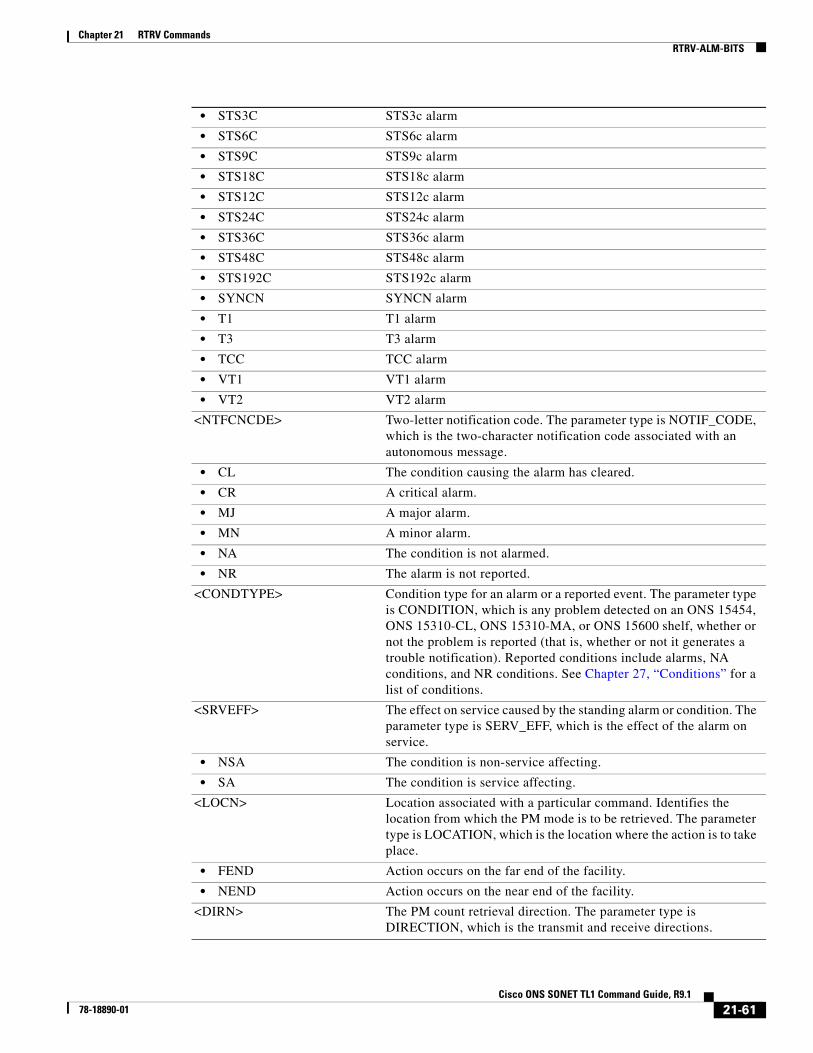
Chapter 21 RTRV CommandsRTRV-ALM-BITS
• STS3C STS3c alarm
• STS6C STS6c alarm
• STS9C STS9c alarm
• STS18C STS18c alarm
• STS12C STS12c alarm
• STS24C STS24c alarm
• STS36C STS36c alarm
• STS48C STS48c alarm
• STS192C STS192c alarm
• SYNCN SYNCN alarm
• T1 T1 alarm
• T3 T3 alarm
• TCC TCC alarm
• VT1 VT1 alarm
• VT2 VT2 alarm
<NTFCNCDE> Two-letter notification code. The parameter type is NOTIF_CODE, which is the two-character notification code associated with an autonomous message.
• CL The condition causing the alarm has cleared.
• CR A critical alarm.
• MJ A major alarm.
• MN A minor alarm.
• NA The condition is not alarmed.
• NR The alarm is not reported.
<CONDTYPE> Condition type for an alarm or a reported event. The parameter type is CONDITION, which is any problem detected on an ONS 15454, ONS 15310-CL, ONS 15310-MA, or ONS 15600 shelf, whether or not the problem is reported (that is, whether or not it generates a trouble notification). Reported conditions include alarms, NA conditions, and NR conditions. See Chapter 27, “Conditions” for a list of conditions.
<SRVEFF> The effect on service caused by the standing alarm or condition. The parameter type is SERV_EFF, which is the effect of the alarm on service.
• NSA The condition is non-service affecting.
• SA The condition is service affecting.
<LOCN> Location associated with a particular command. Identifies the location from which the PM mode is to be retrieved. The parameter type is LOCATION, which is the location where the action is to take place.
• FEND Action occurs on the far end of the facility.
• NEND Action occurs on the near end of the facility.
<DIRN> The PM count retrieval direction. The parameter type is DIRECTION, which is the transmit and receive directions.
21-61Cisco ONS SONET TL1 Command Guide, R9.1
78-18890-01

Chapter 21 RTRV CommandsRTRV-ALM-ENV
21.12 RTRV-ALM-ENV(Cisco ONS 15454, 15327, 15600, 15310) The Retrieve Alarm Environment (RTRV-ALM-ENV) command retrieves the environmental alarms.
Usage Guidelines None
Category Environment
Security Retrieve
Input Format RTRV-ALM-ENV:[<TID>]:<AID>:<CTAG>::[<NTFCNCDE>],[<ALMTYPE>];
Input Example RTRV-ALM-ENV:CISCO:ENV-IN-1:123::MJ,OPENDR;
Input Parameters
• BTH Both transmit and receive directions
• RCV Receive direction only
<DESC> (Optional) A condition description. DESC is a string.
<AID> Access identifier from the “26.13 ENV” section on page 32.
Note For RTRV-ALM-ENV, only ENV-IN-{1-4} is a valid AID for ONS 15454. ENV-OUT-{1,6} is not a valid AID for RTRV-ALM-ENV.
<NTFCNCDE> Two-letter notification code. A null value is equivalent to ALL. The parameter type is NOTIF_CODE, which is the two-character notification code associated with an autonomous message.
• CL The condition causing the alarm has cleared.
• CR A critical alarm.
• MJ A major alarm.
• MN A minor alarm.
• NA The condition is not alarmed.
• NR The alarm is not reported.
<ALMTYPE> The alarm type for the environmental alarm. A null value is equivalent to ALL. The parameter type is ENV_ALM, which is the environmental alarm types.
• AIRCOMPR Air compressor failure
• AIRCOND Air conditioning failure
• AIRDRYR Air dryer failure
21-62Cisco ONS SONET TL1 Command Guide, R9.1
78-18890-01

Chapter 21 RTRV CommandsRTRV-ALM-ENV
• BATDSCHRG Battery discharging
• BATTERY Battery failure
• CLFAN Cooling fan failure
• CPMAJOR Centralized power major failure
• CPMINOR Centralized power minor failure
• ENGINE Engine failure
• ENGOPRG Engine operating
• ENGTRANS Standby engine transfer
• EXPLGS Explosive gas
• FIRDETR Fire detector failure
• FIRE Fire
• FLOOD Flood
• FUELLEAK Fuel leak
• FUSE Fuse failure
• GASALARM Explosive gas, toxic gas, ventilation fail, or gas monitor fail
• HATCH Controlled Environment Vault (CEV) hatch fail
• GEN Generator failure
• HIAIR High airflow
• HIHUM High humidity
• HITEMP High temperature
• HIWTR High water
• INTRUDER Intrusion
• LEVELCON Level converter
• LVDADSL Secondary ADSL low voltage disconnect
• LVDBYPAS Low voltage disconnected bypass
• LWBATVG Low battery voltage
• LWFUEL Low fuel
• LWHUM Low humidity
• LWPRES Low cable pressure
• LWTEMP Low temperature
• LWWTR Low water
• MISC Miscellaneous
• OPENDR Open door
• POWER Commercial power failure
• PUMP Pump failure
• PWR-48 48 V power supply failure
• PWR-139 –139 V power converter
• PWR-190 –190 V power converter
• PWRMJ Power supply major
• PWRMN Power supply minor
• RECT Rectifier failure
21-63Cisco ONS SONET TL1 Command Guide, R9.1
78-18890-01

Chapter 21 RTRV CommandsRTRV-ALM-ENV
Output Format SID DATE TIMEM CTAG COMPLD “<AID>:<NTFCNCDE>,<ALMTYPE>,[<OCRDAT>],[<OCRTM>],[<DESC>]”
;
Output Example TID-000 1998-06-20 14:30:00M 001 COMPLD “ENV-IN-1:MJ,OPENDR,08-01,14-25-59,\“OPEN DOOR\””;
Output Parameters
• RECTHI Rectifier high voltage
• RECTLO Rectifier low voltage
• RINGGENMJ Ringing generator major
• RINGGENMN Ringing generator minor
• RTACADSL AC or AC/rectifier power fail ADSL equipment
• RTACCRIT AC or AC/rectifier power fail DCL equipment critical site
• RTACPWR AC or AC/rectifier power fail DCL equipment
• RTACPWRENG Commercial AC fail, site equipped with standby engine
• RTBAYPWR AC power loss distributed power RT bay
• RTRVENG Retrieve standby engine, commercial AC restored
• SMOKE Smoke
• TEMP High-low temperature
• TOXICGAS Toxic gas
• TREPEATER T-repeater shelf
• VENTN Ventilation system failure
<AID> Access identifier from the “26.13 ENV” section on page 32.
<NTFCNCDE> Two-letter notification code. The parameter type is NOTIF_CODE, which is the two-character notification code associated with an autonomous message.
• CL The condition causing the alarm has cleared.
• CR A critical alarm.
• MJ A major alarm.
• MN A minor alarm.
• NA The condition is not alarmed.
• NR The alarm is not reported.
21-64Cisco ONS SONET TL1 Command Guide, R9.1
78-18890-01

Chapter 21 RTRV CommandsRTRV-ALM-ENV
<CONDTYPE> Condition type for an alarm or a reported event. The parameter type is CONDITION, which is any problem detected on an ONS 15454, ONS 15310-CL, 15310-MA or ONS 15600 shelf, whether or not the problem is reported (that is, whether or not it generates a trouble notification). Reported conditions include alarms, NA conditions, and NR conditions. See Chapter 27, “Conditions” for a list of conditions.
<ALMTYPE> The alarm type for the environmental alarm. A null value is equivalent to ALL. The parameter type is ENV_ALM, which is the environmental alarm types.
• AIRCOMPR Air compressor failure
• AIRCOND Air conditioning failure
• AIRDRYR Air dryer failure
• BATDSCHRG Battery discharging
• BATTERY Battery failure
• CLFAN Cooling fan failure
• CPMAJOR Centralized power major failure
• CPMINOR Centralized power minor failure
• ENGINE Engine failure
• ENGOPRG Engine operating
• ENGTRANS Standby engine transfer
• EXPLGS Explosive gas
• FIRDETR Fire detector failure
• FIRE Fire
• FLOOD Flood
• FUELLEAK Fuel leak
• FUSE Fuse failure
• GASALARM Explosive gas, toxic gas, ventilation fail, or gas monitor fail
• HATCH CEV hatch fail
• GEN Generator failure
• HIAIR High airflow
• HIHUM High humidity
• HITEMP High temperature
• HIWTR High water
• INTRUDER Intrusion
• LEVELCON Level converter
• LVDADSL Secondary ADSL low voltage disconnect
• LVDBYPAS Low voltage disconnected bypass
• LWBATVG Low battery voltage
• LWFUEL Low fuel
• LWHUM Low humidity
• LWPRES Low cable pressure
• LWTEMP Low temperature
21-65Cisco ONS SONET TL1 Command Guide, R9.1
78-18890-01
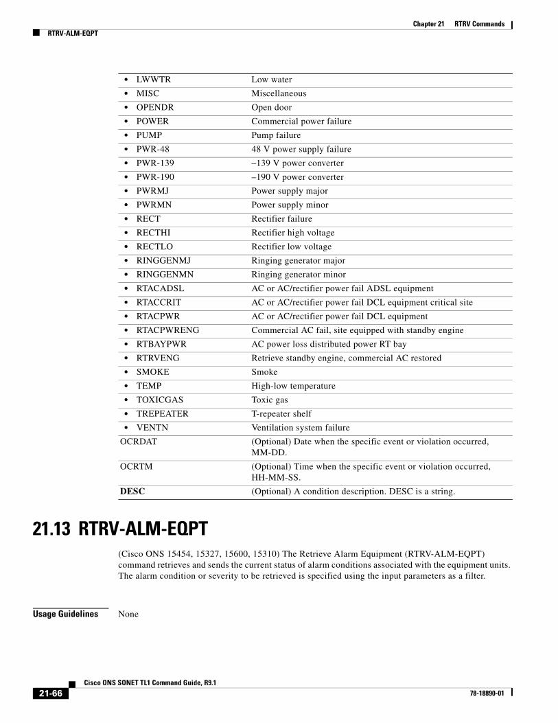
Chapter 21 RTRV CommandsRTRV-ALM-EQPT
21.13 RTRV-ALM-EQPT(Cisco ONS 15454, 15327, 15600, 15310) The Retrieve Alarm Equipment (RTRV-ALM-EQPT) command retrieves and sends the current status of alarm conditions associated with the equipment units. The alarm condition or severity to be retrieved is specified using the input parameters as a filter.
Usage Guidelines None
• LWWTR Low water
• MISC Miscellaneous
• OPENDR Open door
• POWER Commercial power failure
• PUMP Pump failure
• PWR-48 48 V power supply failure
• PWR-139 –139 V power converter
• PWR-190 –190 V power converter
• PWRMJ Power supply major
• PWRMN Power supply minor
• RECT Rectifier failure
• RECTHI Rectifier high voltage
• RECTLO Rectifier low voltage
• RINGGENMJ Ringing generator major
• RINGGENMN Ringing generator minor
• RTACADSL AC or AC/rectifier power fail ADSL equipment
• RTACCRIT AC or AC/rectifier power fail DCL equipment critical site
• RTACPWR AC or AC/rectifier power fail DCL equipment
• RTACPWRENG Commercial AC fail, site equipped with standby engine
• RTBAYPWR AC power loss distributed power RT bay
• RTRVENG Retrieve standby engine, commercial AC restored
• SMOKE Smoke
• TEMP High-low temperature
• TOXICGAS Toxic gas
• TREPEATER T-repeater shelf
• VENTN Ventilation system failure
OCRDAT (Optional) Date when the specific event or violation occurred, MM-DD.
OCRTM (Optional) Time when the specific event or violation occurred, HH-MM-SS.
DESC (Optional) A condition description. DESC is a string.
21-66Cisco ONS SONET TL1 Command Guide, R9.1
78-18890-01

Chapter 21 RTRV CommandsRTRV-ALM-EQPT
Category Equipment
Security Retrieve
Input Format RTRV-ALM-EQPT:[<TID>]:<AID>:<CTAG>::[<NTFCNCDE>],[<CONDTYPE>],[<SRVEFF>],[<LOCN>],[<DIRN>];
Input Example RTRV-ALM-EQPT:TWOROCK:SLOT-7:227::MJ,HITEMP,NSA;
Input Parameters <AID> Access identifier from the “26.14 EQPT” section on page 33.
<NTFCNCDE> Two-letter notification code. A null value is equivalent to ALL. The parameter type is NOTIF_CODE, which is the two-character notification code associated with an autonomous message.
• CL The condition causing the alarm has cleared.
• CR A critical alarm.
• MJ A major alarm.
• MN A minor alarm.
• NA The condition is not alarmed.
• NR The alarm is not reported.
<CONDTYPE> The condition type for an alarm or a reported event. A null value is equivalent to ALL. The parameter type is CONDITION, which is any problem detected on an ONS 15454, ONS 15310-CL, ONS 15310-MA or ONS 15600 shelf, whether or not the problem is reported (that is, whether or not it generates a trouble notification). Reported conditions include alarms, NA conditions, and NR conditions. See Chapter 27, “Conditions” for a list of conditions.
<SRVEFF> The effect on service caused by the standing alarm or condition. The parameter type is SERV_EFF, which is the effect of the alarm on service. A null value is equivalent to ALL.
• NSA The condition is non-service affecting.
• SA The condition is service affecting.
<LOCN> Location associated with a particular command. Identifies the location from which the PM mode is to be retrieved. The parameter type is LOCATION, which is the location where the action is to take place.
• FEND Action occurs on the far end of the facility.
• NEND Action occurs on the near end of the facility.
<DIRN> The PM count retrieval direction. The parameter type is DIRECTION, which is the transmit and receive directions.
• BTH Both transmit and receive directions
• RCV Receive direction only
21-67Cisco ONS SONET TL1 Command Guide, R9.1
78-18890-01
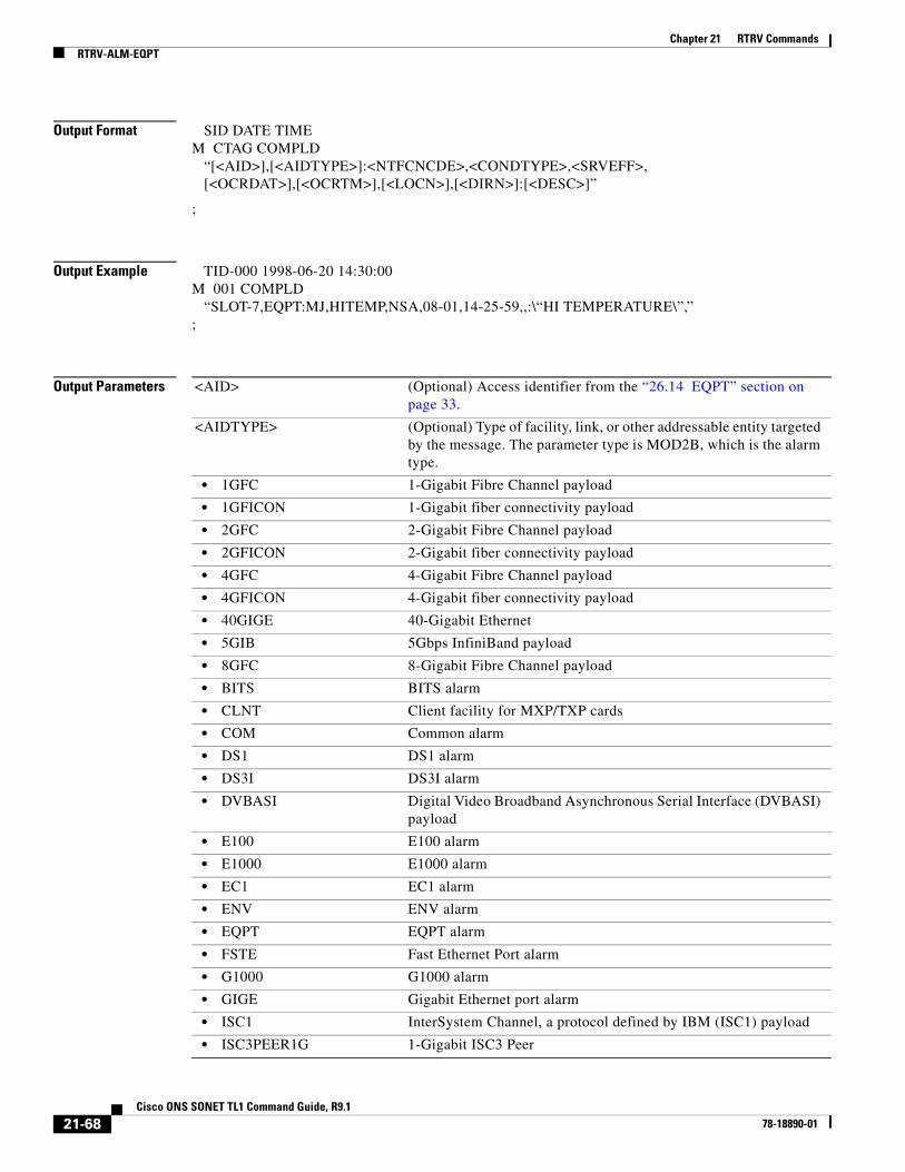
Chapter 21 RTRV CommandsRTRV-ALM-EQPT
Output Format SID DATE TIMEM CTAG COMPLD “[<AID>],[<AIDTYPE>]:<NTFCNCDE>,<CONDTYPE>,<SRVEFF>, [<OCRDAT>],[<OCRTM>],[<LOCN>],[<DIRN>]:[<DESC>]”
;
Output Example TID-000 1998-06-20 14:30:00M 001 COMPLD “SLOT-7,EQPT:MJ,HITEMP,NSA,08-01,14-25-59,,:\“HI TEMPERATURE\”,”;
Output Parameters <AID> (Optional) Access identifier from the “26.14 EQPT” section on page 33.
<AIDTYPE> (Optional) Type of facility, link, or other addressable entity targeted by the message. The parameter type is MOD2B, which is the alarm type.
• 1GFC 1-Gigabit Fibre Channel payload
• 1GFICON 1-Gigabit fiber connectivity payload
• 2GFC 2-Gigabit Fibre Channel payload
• 2GFICON 2-Gigabit fiber connectivity payload
• 4GFC 4-Gigabit Fibre Channel payload
• 4GFICON 4-Gigabit fiber connectivity payload
• 40GIGE 40-Gigabit Ethernet
• 5GIB 5Gbps InfiniBand payload
• 8GFC 8-Gigabit Fibre Channel payload
• BITS BITS alarm
• CLNT Client facility for MXP/TXP cards
• COM Common alarm
• DS1 DS1 alarm
• DS3I DS3I alarm
• DVBASI Digital Video Broadband Asynchronous Serial Interface (DVBASI) payload
• E100 E100 alarm
• E1000 E1000 alarm
• EC1 EC1 alarm
• ENV ENV alarm
• EQPT EQPT alarm
• FSTE Fast Ethernet Port alarm
• G1000 G1000 alarm
• GIGE Gigabit Ethernet port alarm
• ISC1 InterSystem Channel, a protocol defined by IBM (ISC1) payload
• ISC3PEER1G 1-Gigabit ISC3 Peer
21-68Cisco ONS SONET TL1 Command Guide, R9.1
78-18890-01

Chapter 21 RTRV CommandsRTRV-ALM-EQPT
• ISC3PEER2G 2-Gigabit ISC3 Peer
• ISC3PEER2R 1-Gigabit or 2-Gigabit ISC3 peer used in transparent (2R) mode
• ISCCOMPAT 1-Gigabit ISC1, ISC2, and ISC3 compatibility
• OC3 OC3 alarm
• OC12 OC12 alarm
• OC48 OC48 alarm
• OC192 OC192 alarm
• OC768 OC768 alarm
• OCH Optical channel
• OMS Optical Multiplex Section
• OTS Optical Transport Section
• OTU3 Optical Transport Unit Level 3
• POS POS port alarm
• STS1 STS1 alarm
• STS3C STS3c alarm
• STS6C STS6c alarm
• STS9C STS9c alarm
• STS18C STS18c alarm
• STS12C STS12c alarm
• STS24C STS24c alarm
• STS36C STS36c alarm
• STS48C STS48c alarm
• STS192C STS192c alarm
• SYNCN SYNCN alarm
• T1 T1 alarm
• T3 T3 alarm
• TCC TCC alarm
• VT1 VT1 alarm
• VT2 VT2 alarm
<NTFCNCDE> Two-letter notification code. The parameter type is NOTIF_CODE, which is the two-character notification code associated with an autonomous message.
• CL The condition causing the alarm has cleared.
• CR A critical alarm.
• MJ A major alarm.
• MN A minor alarm.
• NA The condition is not alarmed.
• NR The alarm is not reported.
21-69Cisco ONS SONET TL1 Command Guide, R9.1
78-18890-01

Chapter 21 RTRV CommandsRTRV-ALM-SYNCN
21.14 RTRV-ALM-SYNCN(Cisco ONS 15454, 15327, 15600, 15310) The Retrieve Alarm Synchronization (RTRV-ALM-SYNCN) command retrieves and sends the current status of alarm conditions associated with a synchronization facility. The alarm condition or severity to be retrieved can be specified by using the input parameters as a filter.
Usage Guidelines None
Category Synchronization
Security Retrieve
<CONDTYPE> Condition type for an alarm or a reported event. The parameter type is CONDITION, which is any problem detected on an ONS 15454, ONS 15310-CL, ONS 15310-MA or ONS 15600 shelf, whether or not the problem is reported (that is, whether or not it generates a trouble notification). Reported conditions include alarms, NA conditions, and NR conditions. See Chapter 27, “Conditions” for a list of conditions.
<SRVEFF> The effect on service caused by the standing alarm or condition. The parameter type is SERV_EFF, which is the effect of the alarm on service.
• NSA The condition is non-service affecting.
• SA The condition is service affecting.
<LOCN> Location associated with a particular command. Identifies the location from which the PM mode is to be retrieved. The parameter type is LOCATION, which is the location where the action is to take place.
• FEND Action occurs on the far end of the facility.
• NEND Action occurs on the near end of the facility.
<DIRN> The PM count retrieval direction. The parameter type is DIRECTION, which is the transmit and receive directions.
• BTH Both transmit and receive directions
• RCV Receive direction only
<OCRDAT> (Optional) Date when the specific event or violation occurred, MM-DD.
<OCRTM> (Optional) Time when the specific event or violation occurred, HH-MM-SS.
<DESC> (Optional) A condition description. DESC is a string.
21-70Cisco ONS SONET TL1 Command Guide, R9.1
78-18890-01

Chapter 21 RTRV CommandsRTRV-ALM-SYNCN
Input Format RTRV-ALM-SYNCN:[<TID>]:<AID>:<CTAG>::[<NTFCNCDE>],[<CONDTYPE>],[<SRVEFF>],[<LOCN>],[<DIRN>];
Input Example RTRV-ALM-SYNCN:FULTON:SYNC-NE:226::CR,FAILTOSW,SA;
Input Parameters
Output Format SID DATE TIMEM CTAG COMPLD “<AID>,[<AIDTYPE>]:<NTFCNCDE>,<CONDTYPE>,<SRVEFF>, [<OCRDAT>],[<OCRTM>],[<LOCN>],[<DIRN>]:[<DESC>]”
;
<AID> Access identifier from the “26.28 SYNC_REF” section on page 51.
<NTFCNCDE> Two-letter notification code. A null value is equivalent to ALL. The parameter type is NOTIF_CODE, which is the two-character notification code associated with an autonomous message.
• CL The condition causing the alarm has cleared.
• CR A critical alarm.
• MJ A major alarm.
• MN A minor alarm.
• NA The condition is not alarmed.
• NR The alarm is not reported.
<CONDTYPE> The condition type for an alarm or a reported event. A null value is equivalent to ALL. The parameter type is CONDITION, which is any problem detected on an ONS 15454, ONS 15310-CL, ONS 15310-MA or ONS 15600 shelf, whether or not the problem is reported (that is, whether or not it generates a trouble notification). Reported conditions include alarms, NA conditions, and NR conditions. See Chapter 27, “Conditions” for a list of conditions.
<SRVEFF> The effect on service caused by the standing alarm or condition. The parameter type is SERV_EFF, which is the effect of the alarm on service. A null value is equivalent to ALL.
• NSA The condition is non-service affecting.
• SA The condition is service affecting.
<LOCN> Location associated with a particular command. Identifies the location from which the PM mode is to be retrieved. The parameter type is LOCATION, which is the location where the action is to take place.
• FEND Action occurs on the far end of the facility.
• NEND Action occurs on the near end of the facility.
<DIRN> The PM count retrieval direction. The parameter type is DIRECTION, which is the transmit and receive directions.
• BTH Both transmit and receive directions
• RCV Receive direction only
21-71Cisco ONS SONET TL1 Command Guide, R9.1
78-18890-01

Chapter 21 RTRV CommandsRTRV-ALM-SYNCN
Output Example TID-000 1998-06-20 14:30:00M 001 COMPLD “SYNC-NE,SYNCN:CR,FAILTOSW,SA,08-01, 14-25-59,,:\“FAILURE TO SWITCH TO PROTECTION\”,”;
Output Parameters <AID> Access identifier from the “26.26 SYN” section on page 50.
<AIDTYPE> (Optional) Type of facility, link or other addressable entity targeted by the message. The parameter type is MOD2B, which is the alarm type.
• 1GFC 1-Gigabit Fibre Channel payload
• 1GFICON 1-Gigabit fiber connectivity payload
• 2GFC 2-Gigabit Fibre Channel payload
• 2GFICON 2-Gigabit fiber connectivity payload
• 4GFC 4-Gigabit Fibre Channel payload
• 4GFICON 4-Gigabit fiber connectivity payload
• 40GIGE 40-Gigabit Ethernet
• 5GIB 5Gbps InfiniBand payload
• 8GFC 8-Gigabit Fibre Channel payload
• BITS BITS alarm
• CLNT Client facility for MXP/TXP cards
• COM Common alarm
• DS1 DS1 alarm
• DS3I DS3I alarm
• DVBASI Digital Video Broadband Asynchronous Serial Interface (DVBASI) payload
• E100 E100 alarm
• E1000 E1000 alarm
• EC1 EC1 alarm
• ENV ENV alarm
• EQPT EQPT alarm
• FSTE Fast Ethernet Port alarm
• G1000 G1000 alarm
• GIGE Gigabit Ethernet port alarm
• ISC1 InterSystem Channel, a protocol defined by IBM (ISC1) payload
• ISC3PEER1G 1-Gigabit ISC3 Peer
• ISC3PEER2G 2-Gigabit ISC3 Peer
• ISC3PEER2R 1-Gigabit or 2-Gigabit ISC3 peer used in transparent (2R) mode
• ISCCOMPAT 1-Gigabit ISC1, ISC2, and ISC3 compatibility
• OC3 OC3 alarm
• OC12 OC12 alarm
• OC48 OC48 alarm
21-72Cisco ONS SONET TL1 Command Guide, R9.1
78-18890-01

Chapter 21 RTRV CommandsRTRV-ALM-SYNCN
• OC192 OC192 alarm
• OC768 OC768 alarm
• OCH Optical channel
• OMS Optical Multiplex Section
• OTS Optical Transport Section
• OTU3 Optical Transport Unit Level 3
• POS POS port alarm
• STS1 STS1 alarm
• STS3C STS3c alarm
• STS6C STS6c alarm
• STS9C STS9c alarm
• STS18C STS18c alarm
• STS12C STS12c alarm
• STS24C STS24c alarm
• STS36C STS36c alarm
• STS48C STS48c alarm
• STS192C STS192c alarm
• SYNCN SYNCN alarm
• T1 T1 alarm
• T3 T3 alarm
• TCC TCC alarm
• VT1 VT1 alarm
• VT2 VT2 alarm
<NTFCNCDE> Two-letter notification code. The parameter type is NOTIF_CODE, which is the two-character notification code associated with an autonomous message.
• CL The condition causing the alarm has cleared.
• CR A critical alarm.
• MJ A major alarm.
• MN A minor alarm.
• NA The condition is not alarmed.
• NR The alarm is not reported.
<CONDTYPE> Condition type for an alarm or a reported event. The parameter type is CONDITION, which is any problem detected on an ONS 15454, ONS 15310-CL, ONS 15310-MA or ONS 15600 shelf, whether or not the problem is reported (that is, whether or not it generates a trouble notification). Reported conditions include alarms, NA conditions, and NR conditions. See Chapter 27, “Conditions” for a list of conditions.
<SRVEFF> The effect on service caused by the standing alarm or condition. The parameter type is SERV_EFF, which is the effect of the alarm on service.
• NSA The condition is non-service affecting.
• SA The condition is service affecting.
21-73Cisco ONS SONET TL1 Command Guide, R9.1
78-18890-01

Chapter 21 RTRV CommandsRTRV-ALMTH-<MOD2>
21.15 RTRV-ALMTH-<MOD2>(Cisco ONS 15310-CL, Cisco ONS 15310-MA, Cisco ONS 15454, and Cisco ONS 15600) The Retrieve Alarm Threshold for 10GFC, 10GIGE, 40GIGE, 1GFC, 1GFICON, 2GFC, 2GFICON, 5GIB, 8GFC, CLNT, D1VIDEO, DS1, DV6000, DVBASI, E1, E3, E4, EC1, ESCON, ETRCLO, ETH, FSTE, G1000, GFPOS, GIGE, HDTV, ISC1, ILK, ISCCOMPAT, ISC3PEER2R, ISC3PEER1G, ISC3PEER2G, OC12, OC192, OC3, OC48, OC768, OCH, OMS, OTS, OTU3, POS, STS1, STS12C, STS18C, STS192C, STS24C, STS36C, STS3C, STS48C, STS6C, STS9C, T1, T3, VC12, VC3, VT1, or VT2 (RTRV-ALMTH-<MOD2>) command retrieves the alarm threshold values. The only applicable MOD2 values are OC3, OC12, OC48, OC192, OCH, OMS, and OTS.
Usage Guidelines None
Category Fault
Security Retrieve
Input Format RTRV-ALMTH-<MOD2>:[<TID>]:<AID>:<CTAG>::[<CONDTYPE>][,,::];
Input Example RTRV-ALMTH-{MOD2}::CHAN-2-2:1::OPT-HIGH;
<LOCN> Location associated with a particular command. Identifies the location from which the PM mode is to be retrieved. The parameter type is LOCATION, which is the location where the action is to take place.
• FEND Action occurs on the far end of the facility.
• NEND Action occurs on the near end of the facility.
<DIRN> The PM count retrieval direction. The parameter type is DIRECTION, which is the transmit and receive directions.
• BTH Both transmit and receive directions
• RCV Receive direction only
<OCRDAT> (Optional) Date when the specific event or violation occurred, MM-DD.
<OCRTM> (Optional) Time when the specific event or violation occurred, HH-MM-SS.
<DESC> (Optional) A condition description. DESC is a string.
21-74Cisco ONS SONET TL1 Command Guide, R9.1
78-18890-01
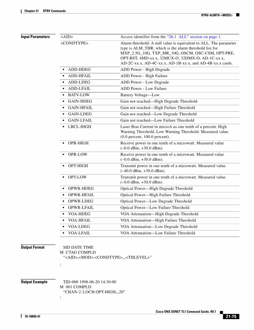
Chapter 21 RTRV CommandsRTRV-ALMTH-<MOD2>
Input Parameters
Output Format SID DATE TIMEM CTAG COMPLD “<AID>,<MOD>:<CONDTYPE>,,,<THLEVEL>”
;
Output Example TID-000 1998-06-20 14:30:00M 001 COMPLD “CHAN-2-2,OCH:OPT-HIGH,,,20”;
<AID> Access identifier from the “26.1 ALL” section on page 1.
<CONDTYPE> Alarm threshold. A null value is equivalent to ALL. The parameter type is ALM_THR, which is the alarm threshold list for MXP_2.5G_10G, TXP_MR_10G, OSCM, OSC-CSM, OPT-PRE, OPT-BST, 4MD-xx.x, 32MUX-O, 32DMX-O, AD-1C-xx.x, AD-2C-xx.x, AD-4C-xx.x, AD-1B-xx.x, and AD-4B-xx.x cards.
• ADD-HDEG ADD Power - High Degrade
• ADD-HFAIL ADD Power - High Failure
• ADD-LDEG ADD Power - Low Degrade
• ADD-LFAIL ADD Power - Low Failure
• BATV-LOW Battery Voltage—Low
• GAIN-HDEG Gain not reached—High Degrade Threshold
• GAIN-HFAIL Gain not reached—High Failure Threshold
• GAIN-LDEG Gain not reached—Low Degrade Threshold
• GAIN-LFAIL Gain not reached—Low Failure Threshold
• LBCL-HIGH Laser Bias Current in microA as one tenth of a percent. High Warning Threshold, Low Warning Threshold. Measured value (0.0 percent, 100.0 percent).
• OPR-HIGH Receive power in one tenth of a microwatt. Measured value (–0.0 dBm, +30.0 dBm).
• OPR-LOW Receive power in one tenth of a microwatt. Measured value (–0.0 dBm, +30.0 dBm).
• OPT-HIGH Transmit power in one tenth of a microwatt. Measured value (–40.0 dBm, +30.0 dBm).
• OPT-LOW Transmit power in one tenth of a microwatt. Measured value (–0.0 dBm, +30.0 dBm).
• OPWR-HDEG Optical Power—High Degrade Threshold
• OPWR-HFAIL Optical Power—High Failure Threshold
• OPWR-LDEG Optical Power—Low Degrade Threshold
• OPWR-LFAIL Optical Power—Low Failure Threshold
• VOA-HDEG VOA Attenuation—High Degrade Threshold
• VOA-HFAIL VOA Attenuation—High Failure Threshold
• VOA-LDEG VOA Attenuation—Low Degrade Threshold
• VOA-LFAIL VOA Attenuation—Low Failure Threshold
21-75Cisco ONS SONET TL1 Command Guide, R9.1
78-18890-01

Chapter 21 RTRV CommandsRTRV-ALMTH-<MOD2>
Output Parameters <AID> Access identifier from the “26.1 ALL” section on page 1.
<MOD> AID type. The parameter type is MOD2, which is the line/path modifier.
• 10GFC 10-Gigabit Fibre Channel payload
• 10GFICON 10-Gigabit fiber connectivity payload
• 1GFC 1-Gigabit Fibre Channel payload
• 1GFICON 1-Gigabit fiber connectivity payload
• 1GISC3 1-Gigabit ISC3 compatible
• 2GFC 2-Gigabit Fibre Channel payload
• 2GFICON 2-Gigabit fiber connectivity payload
• 2GISC3 2-Gigabit ISC3 compatible
• 4GFC 4-Gigabit Fibre Channel payload
• 4GFICON 4-Gigabit fiber connectivity payload
• 40GIGE 40-Gigabit Ethernet
• 5GIB 5Gbps InfiniBand payload
• 8GFC 8-Gigabit Fibre Channel payload
• D1VIDEO D1 video
• DS1 DS1 line of a DS3XM card
• DS3I DS3I line
• DV6000 DV6000
• DVBASI Digital Video Broadband Asynchronous Serial Interface (DVBASI) payload
• EC1 EC1 facility
• ESCON ESCON
• ETRCLO ETR_CLO
• FSTE FSTE facility
• G1000 G1000 facility
• GFPOS GFP over POS. Virtual ports partitioned using GFP’s multiplexing capability.
• GIGE Gigabit Ethernet
• HDTV HDTV
• ISC1 InterSystem Channel, a protocol defined by IBM (ISC1) payload
• ISC3PEER1G 1-Gigabit ISC3 Peer
• ISC3PEER2G 2-Gigabit ISC3 Peer
• ISC3PEER2R 1-Gigabit or 2-Gigabit ISC3 peer used in transparent (2R) mode
• ISCCOMPAT 1-Gigabit ISC1, ISC2, and ISC3 compatibility
• OC3 OC-3 facility
• OC12 OC-12 facility
• OC48 OC-48 facility
• OC192 OC-192 facility
• OC768 OC-768 facility
• OCH Optical Channel
21-76Cisco ONS SONET TL1 Command Guide, R9.1
78-18890-01
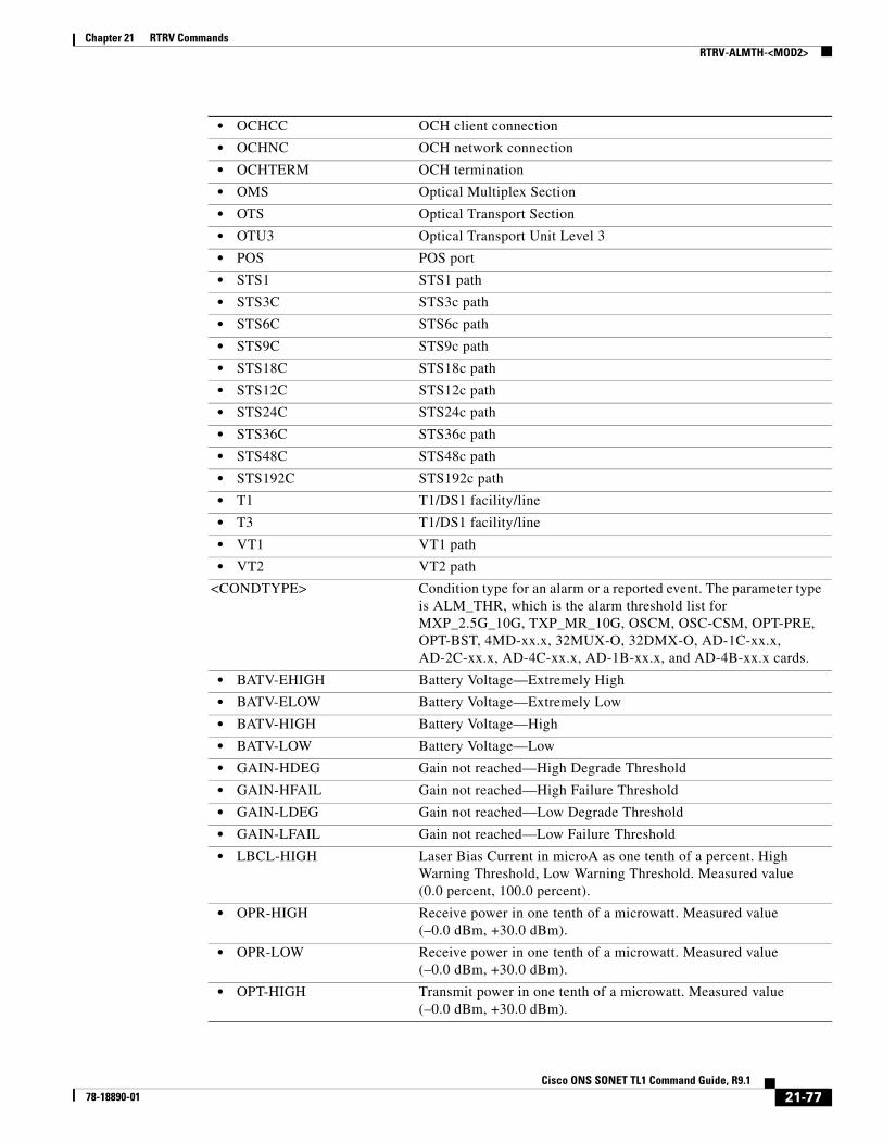
Chapter 21 RTRV CommandsRTRV-ALMTH-<MOD2>
• OCHCC OCH client connection
• OCHNC OCH network connection
• OCHTERM OCH termination
• OMS Optical Multiplex Section
• OTS Optical Transport Section
• OTU3 Optical Transport Unit Level 3
• POS POS port
• STS1 STS1 path
• STS3C STS3c path
• STS6C STS6c path
• STS9C STS9c path
• STS18C STS18c path
• STS12C STS12c path
• STS24C STS24c path
• STS36C STS36c path
• STS48C STS48c path
• STS192C STS192c path
• T1 T1/DS1 facility/line
• T3 T1/DS1 facility/line
• VT1 VT1 path
• VT2 VT2 path
<CONDTYPE> Condition type for an alarm or a reported event. The parameter type is ALM_THR, which is the alarm threshold list for MXP_2.5G_10G, TXP_MR_10G, OSCM, OSC-CSM, OPT-PRE, OPT-BST, 4MD-xx.x, 32MUX-O, 32DMX-O, AD-1C-xx.x, AD-2C-xx.x, AD-4C-xx.x, AD-1B-xx.x, and AD-4B-xx.x cards.
• BATV-EHIGH Battery Voltage—Extremely High
• BATV-ELOW Battery Voltage—Extremely Low
• BATV-HIGH Battery Voltage—High
• BATV-LOW Battery Voltage—Low
• GAIN-HDEG Gain not reached—High Degrade Threshold
• GAIN-HFAIL Gain not reached—High Failure Threshold
• GAIN-LDEG Gain not reached—Low Degrade Threshold
• GAIN-LFAIL Gain not reached—Low Failure Threshold
• LBCL-HIGH Laser Bias Current in microA as one tenth of a percent. High Warning Threshold, Low Warning Threshold. Measured value (0.0 percent, 100.0 percent).
• OPR-HIGH Receive power in one tenth of a microwatt. Measured value (–0.0 dBm, +30.0 dBm).
• OPR-LOW Receive power in one tenth of a microwatt. Measured value (–0.0 dBm, +30.0 dBm).
• OPT-HIGH Transmit power in one tenth of a microwatt. Measured value (–0.0 dBm, +30.0 dBm).
21-77Cisco ONS SONET TL1 Command Guide, R9.1
78-18890-01

Chapter 21 RTRV CommandsRTRV-ALMTH-EQPT
21.16 RTRV-ALMTH-EQPT(Cisco ONS 15454 and ONS 15600) The Retrieve Alarm Threshold Equipment (RTRV-ALMTH-EQPT) command retrieves the alarm thresholds for the power level monitoring on an NE.
Usage Guidelines None
Category Equipment
Security Retrieve
Input Format RTRV-ALMTH-EQPT:[<TID>]:[<AID>]:<CTAG>::[<CONDTYPE>][,,::];
Input Example RTRV-ALMTH-EQPT:::1::BATV-HIGH;
RTRV-ALMTH-EQPT::SHELF-2:1::BATV-HIGH;
Input Parameters
• OPT-LOW Transmit power in one tenth of a microwatt. Measured value (–0.0 dBm, +30.0 dBm).
• OPWR-HDEG Optical Power—High Degrade Threshold
• OPWR-HFAIL Optical Power—High Failure Threshold
• OPWR-LDEG Optical Power—Low Degrade Threshold
• OPWR-LFAIL Optical Power—Low Failure Threshold
• VOA-HDEG VOA Attenuation—High Degrade Threshold
• VOA-HFAIL VOA Attenuation—High Failure Threshold
• VOA-LDEG VOA Attenuation—Low Degrade Threshold
• VOA-LFAIL VOA Attenuation—Low Failure Threshold
<THLEVEL> Threshold level. THLEVEL is a float.
<AID> The node or shelf access identifier from the “26.24 SHELF” section on page 44. If omitted it addresses the node or first shelf of the node.
<CONDTYPE> Must not be null. The parameter type is ALM_THR, which is the alarm threshold list for MXP_2.5G_10G, TXP_MR_10G, OSCM, OSC-CSM, OPT-PRE, OPT-BST, 4MD-xx.x, 32MUX-O, 32DMX-O, AD-1C-xx.x, AD-2C-xx.x, AD-4C-xx.x, AD-1B-xx.x, and AD-4B-xx.x cards.
• BATV-EHIGH Battery Voltage—Extremely High
• BATV-ELOW Battery Voltage—Extremely Low
21-78Cisco ONS SONET TL1 Command Guide, R9.1
78-18890-01

Chapter 21 RTRV CommandsRTRV-ALMTH-EQPT
Output Format SID DATE TIMEM CTAG COMPLD “[<AID>],<MOD2B>:<CONDTYPE>,,,<DNFIELD>”
;
Output Example TID-000 1998-06-20 14:30:00M 001 COMPLD “SHELF-1,EQPT:BATV-HIGH,,,-52.0,”;
TID-000 1998-06-20 14:30:00M 001 COMPLD “,EQPT:BATV-HIGH,,,-52.0,"”;
• BATV-HIGH Battery Voltage—High
• BATV-LOW Battery Voltage—Low
• GAIN-HDEG Gain not reached—High Degrade Threshold
• GAIN-HFAIL Gain not reached—High Failure Threshold
• GAIN-LDEG Gain not reached—Low Degrade Threshold
• GAIN-LFAIL Gain not reached—Low Failure Threshold
• LBCL-HIGH Laser Bias Current in microA as one tenth of a percent. High Warning Threshold, Low Warning Threshold Measured value (0.0 percent, 100.0 percent)
• OPR-HIGH Receive power in one tenth of a microwatt. Measured value (–0.0 dBm, +30.0 dBm).
• OPR-LOW Receive power in one tenth of a microwatt. Measured value (–0.0 dBm, +30.0 dBm).
• OPT-HIGH Transmit power in one tenth of a microwatt. Measured value (–0.0 dBm, +30.0 dBm).
• OPT-LOW Transmit power in one tenth of a microwatt. Measured value (–0.0 dBm, +30.0 dBm).
• OPWR-HDEG Optical Power—High Degrade Threshold
• OPWR-HFAIL Optical Power—High Failure Threshold
• OPWR-LDEG Optical Power—Low Degrade Threshold
• OPWR-LFAIL Optical Power—Low Failure Threshold
• VOA-HDEG VOA Attenuation—High Degrade Threshold
• VOA-HFAIL VOA Attenuation—High Failure Threshold
• VOA-LDEG VOA Attenuation—Low Degrade Threshold
• VOA-LFAIL VOA Attenuation—Low Failure Threshold
21-79Cisco ONS SONET TL1 Command Guide, R9.1
78-18890-01

Chapter 21 RTRV CommandsRTRV-ALMTH-EQPT
Output Parameters <AID> The node or shelf access identifier from the “26.24 SHELF” section on page 44. If omitted, it addresses the node or the first shelf of the node.
<MOD2B> Alarm type. The parameter type is MOD2B, which is the alarm type.
• 1GFC 1-Gigabit Fibre Channel payload
• 1GFICON 1-Gigabit fiber connectivity payload
• 2GFC 2-Gigabit Fibre Channel payload
• 2GFICON 2-Gigabit fiber connectivity payload
• BITS BITS alarm
• CLNT Client facility for MXP/TXP cards
• COM Common alarm
• DS1 DS1 alarm
• DS3I DS3I alarm
• E100 E100 alarm
• E1000 E1000 alarm
• EC1 EC1 alarm
• ENV ENV alarm
• EQPT EQPT alarm
• FSTE Fast Ethernet Port alarm
• G1000 G1000 alarm
• GIGE Gigabit Ethernet port alarm
• ISC3PEER1G 1-Gigabit ISC3 Peer
• ISC3PEER2G 2-Gigabit ISC3 Peer
• ISC3PEER2R 1-Gigabit or 2-Gigabit ISC3 peer used in transparent (2R) mode
• ISCCOMPAT 1-Gigabit ISC1, ISC2, and ISC3 compatibility
• OC3 OC3 alarm
• OC12 OC12 alarm
• OC48 OC48 alarm
• OC192 OC192 alarm
• OCH Optical channel
• OMS Optical Multiplex Section
• OTS Optical Transport Section
• POS POS port alarm
• STS1 STS1 alarm
• STS3C STS3c alarm
• STS6C STS6c alarm
• STS9C STS9c alarm
• STS18C STS18c alarm
• STS12C STS12c alarm
• STS24C STS24c alarm
• STS36C STS36c alarm
• STS48C STS48c alarm
21-80Cisco ONS SONET TL1 Command Guide, R9.1
78-18890-01
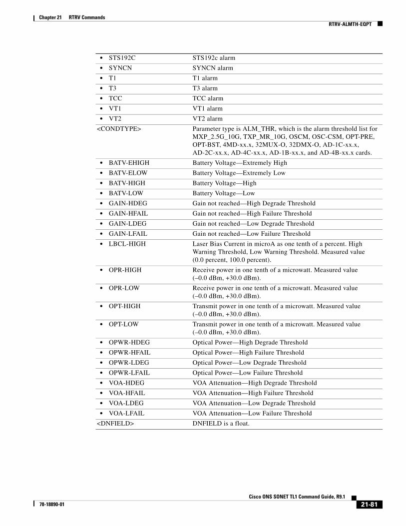
Chapter 21 RTRV CommandsRTRV-ALMTH-EQPT
• STS192C STS192c alarm
• SYNCN SYNCN alarm
• T1 T1 alarm
• T3 T3 alarm
• TCC TCC alarm
• VT1 VT1 alarm
• VT2 VT2 alarm
<CONDTYPE> Parameter type is ALM_THR, which is the alarm threshold list for MXP_2.5G_10G, TXP_MR_10G, OSCM, OSC-CSM, OPT-PRE, OPT-BST, 4MD-xx.x, 32MUX-O, 32DMX-O, AD-1C-xx.x, AD-2C-xx.x, AD-4C-xx.x, AD-1B-xx.x, and AD-4B-xx.x cards.
• BATV-EHIGH Battery Voltage—Extremely High
• BATV-ELOW Battery Voltage—Extremely Low
• BATV-HIGH Battery Voltage—High
• BATV-LOW Battery Voltage—Low
• GAIN-HDEG Gain not reached—High Degrade Threshold
• GAIN-HFAIL Gain not reached—High Failure Threshold
• GAIN-LDEG Gain not reached—Low Degrade Threshold
• GAIN-LFAIL Gain not reached—Low Failure Threshold
• LBCL-HIGH Laser Bias Current in microA as one tenth of a percent. High Warning Threshold, Low Warning Threshold. Measured value (0.0 percent, 100.0 percent).
• OPR-HIGH Receive power in one tenth of a microwatt. Measured value (–0.0 dBm, +30.0 dBm).
• OPR-LOW Receive power in one tenth of a microwatt. Measured value (–0.0 dBm, +30.0 dBm).
• OPT-HIGH Transmit power in one tenth of a microwatt. Measured value (–0.0 dBm, +30.0 dBm).
• OPT-LOW Transmit power in one tenth of a microwatt. Measured value (–0.0 dBm, +30.0 dBm).
• OPWR-HDEG Optical Power—High Degrade Threshold
• OPWR-HFAIL Optical Power—High Failure Threshold
• OPWR-LDEG Optical Power—Low Degrade Threshold
• OPWR-LFAIL Optical Power—Low Failure Threshold
• VOA-HDEG VOA Attenuation—High Degrade Threshold
• VOA-HFAIL VOA Attenuation—High Failure Threshold
• VOA-LDEG VOA Attenuation—Low Degrade Threshold
• VOA-LFAIL VOA Attenuation—Low Failure Threshold
<DNFIELD> DNFIELD is a float.
21-81Cisco ONS SONET TL1 Command Guide, R9.1
78-18890-01

Chapter 21 RTRV CommandsRTRV-ALS
21.17 RTRV-ALS(Cisco ONS 15310-CL, Cisco ONS 15310-MA, Cisco ONS 15454, and Cisco ONS 15600) The Retrieve Automatic Laser Shutoff (RTRV-ALS) command retrieves the ALS attributes of an OC-N facility and all the facilities that support the ALS feature. This command is used to retrieve the ALS parameter of the OC48 and OC192 ports on the MXP_2.5G_10E, TXP_MR_10E, TXP_MR_2.5G, TXPP_MR_2.5G, MXP_2.5G_10G, and TXP_MR_10G cards.
Usage Guidelines None
Category Ports
Security Retrieve
Input Format RTRV-ALS:[<TID>]:<AID>:<CTAG>[::::];
Input Example RTRV-ALS:PENNGROVE:FAC-1-1:1
Input Parameters
Output Format SID DATE TIMEM CTAG COMPLD “<AID>,<AIDTYPE>::[ALSMODE=<ALSMODE>],[ALSRCINT=<ALSRCINT>], [ALSRCPW=<ALSRCPW>],[LSRSTAT=<LSRSTAT>]”
;
Output Example TID-000 1998-06-20 14:30:00M 001 COMPLD “FAC-6-1,OC192::ALSMODE=DISABLED,ALSRCINT=100,ALSRCPW=2.0,LSRSTAT=ON:”;
Output Parameters
<AID> Access identifier from the “26.2 AidUnionId” section on page 12.
<AID> Access identifier from the “26.2 AidUnionId” section on page 12.
<AIDTYPE> Type of access identifier.The parameter type is MOD2, which is the line/path modifier.
• 10GFC 10-Gigabit Fibre Channel payload
• 10GFICON 10-Gigabit fiber connectivity payload
• 1GFC 1-Gigabit Fibre Channel payload
• 1GFICON 1-Gigabit fiber connectivity payload
21-82Cisco ONS SONET TL1 Command Guide, R9.1
78-18890-01

Chapter 21 RTRV CommandsRTRV-ALS
• 1GISC3 1-Gigabit ISC3 compatible
• 2GFC 2-Gigabit Fibre Channel payload
• 2GFICON 2-Gigabit fiber connectivity payload
• 2GISC3 2-Gigabit ISC3 compatible
• 4GFC 4-Gigabit Fibre Channel payload
• 4GFICON 4-Gigabit fiber connectivity payload
• 40GIGE 40-Gigabit Ethernet
• 5GIB 5Gbps InfiniBand payload
• 8GFC 8-Gigabit Fibre Channel payload
• D1VIDEO D1 video
• DS1 DS1 line of a DS3XM card
• DS3I DS3I line
• DV6000 DV6000
• DVBASI Digital Video Broadband Asynchronous Serial Interface (DVBASI) payload
• EC1 EC1 facility
• ESCON ESCON
• ETRCLO ETR_CLO
• FSTE FSTE facility
• G1000 G1000 facility
• GFPOS GFP over POS. Virtual ports partitioned using GFP’s multiplexing capability.
• GIGE Gigabit Ethernet
• HDTV HDTV
• ISC1 InterSystem Channel, a protocol defined by IBM (ISC1) payload
• ISC3PEER1G 1-Gigabit ISC3 Peer
• ISC3PEER2G 2-Gigabit ISC3 Peer
• ISC3PEER2R 1-Gigabit or 2-Gigabit ISC3 peer used in transparent (2R) mode
• ISCCOMPAT 1-Gigabit ISC1, ISC2, and ISC3 compatibility
• OC3 OC-3 facility
• OC12 OC-12 facility
• OC48 OC-48 facility
• OC192 OC-192 facility
• OC768 OC768 facility
• OCH Optical Channel
• OCHCC OCH client connection
• OCHNC OCH network connection
• OCHTERM OCH termination
• OMS Optical Multiplex Section
• OTS Optical Transport Section
• OTU3 Optical Transport Unit Level 3
• POS POS port
21-83Cisco ONS SONET TL1 Command Guide, R9.1
78-18890-01

Chapter 21 RTRV CommandsRTRV-APC
21.18 RTRV-APC(Cisco ONS 15454) The Operate Amplifier Power Control (RTRV-APC) command retrieves the APC application attributes.
Usage Guidelines None
Category DWDM
Security Maintenance
• STS1 STS1 path
• STS3C STS3c path
• STS6C STS6c path
• STS9C STS9c path
• STS18C STS18c path
• STS12C STS12c path
• STS24C STS24c path
• STS36C STS36c path
• STS48C STS48c path
• STS192C STS192c path
• T1 T1/DS1 facility/line
• T3 T1/DS1 facility/line
• VT1 VT1 path
• VT2 VT2 path
<ALSMODE> ALS is enabled or disabled. The parameter type is ALS_MODE, which is the working mode for automatic laser shutdown.
• AUTO Automatic
• DISABLED Disabled
• MAN Manual
• MAN-RESTART Manual restart for test
<ALSRCINT> (Optional) ALS interval. The range is 60 to 300 seconds. ALSRCINT is an integer.
<ALSRCPW> (Optional) ALS recovery pulse width. The range is 2.0 to 100.00 seconds, in increments of 100 ms. ALSRCPW is a float.
<LSRSTAT> (Optional) Status of the laser. The parameter type is LASER_STATUS (laser status).
• APR Laser is switched on but is working automatic power reduction.
• OFF Laser is switched off.
• ON Laser is switched on.
21-84Cisco ONS SONET TL1 Command Guide, R9.1
78-18890-01

Chapter 21 RTRV CommandsRTRV-ATTR-CONT
Input Format RTRV-APC:[<TID>]::<CTAG>;
Input Example RTRV-APC:PENNGROVE:WDMSIDE-A:114;
Input Parameters None that require description
Output Format SID DATE TIMEM CTAG COMPLD “::[APCENABLE=<APCENABLE>],[APCSTATE=<APCSTATE>]”;
Output Example TID-000 1998-06-20 14:30:00M 001 COMPLD “::APCENABLE=Y,APCSTATE=WORKING”;
Output Parameters
21.19 RTRV-ATTR-CONT(Cisco ONS 15454, 15327, 15600, 15310) The Retrieve Attribute Control (RTRV-ATTR-CONT) command retrieves and sends the attributes associated with an external control. These attributes are used when an external control is operated or released. To set these attributes, use the SET-ATTR-CONT command.
Usage Guidelines None
<WDMSIDE> The AID is used to access the WDM side of an MSTP node.
• WDMSIDE-{UNKNOWN,A,B,C,D,E,F,G,H}
MSTP side identifier
<APCENABLE> (Optional) Enable or disable the APC application. The parameter type is ON_OFF (disable or enable an attribute).
• N Disable an attribute.
• Y Enable an attribute.
<APCSTATE> (Optional) Indicates the status of the APC application. The parameter type is APC_STATE (APC status).
• DISABLE The APC is disabled by the user and is not working.
• FORCED-DISABLE The APC has been internally disabled by the node and is not working.
• WORKING The APC is enabled by the user and is working.
21-85Cisco ONS SONET TL1 Command Guide, R9.1
78-18890-01

Chapter 21 RTRV CommandsRTRV-ATTR-CONT
Category Environment
Security Retrieve
Input Format RTRV-ATTR-CONT:[<TID>]:<AID>:<CTAG>[::<CONTTYPE>];
Input Example RTRV-ATTR-CONT:CISCO:ENV-OUT-2:123::AIRCOND;
Input Parameters
Output Format SID DATE TIMEM CTAG COMPLD “<AID>:[<CONTTYPE>]”;
Output Example TID-000 1998-06-20 14:30:00M 001 COMPLD “ENV-OUT-2:AIRCOND”;
Output Parameters
<AID> Access identifier from the “26.13 ENV” section on page 32. Identifies the external control for which attributes are being set.
<CONTTYPE> Environmental control type. A null value is equivalent to ALL. The parameter type is CONTTYPE, which is the environmental control type.
• AUDIBLE ONS 15310-MA only
• AIRCOND Air conditioning
• ENGINE Engine
• FAN Fan
• GEN Generator
• HEAT Heat
• LIGHT Light
• MISC Miscellaneous
• SPKLR Sprinkler
<AID> Access identifier from the “26.13 ENV” section on page 32. Identifies the external control for which attributes are being set.
<CONTTYPE> Environmental control type. A null value is equivalent to ALL. The parameter type is CONTTYPE, which is the environmental control type.
• AIRCOND Air conditioning
21-86Cisco ONS SONET TL1 Command Guide, R9.1
78-18890-01
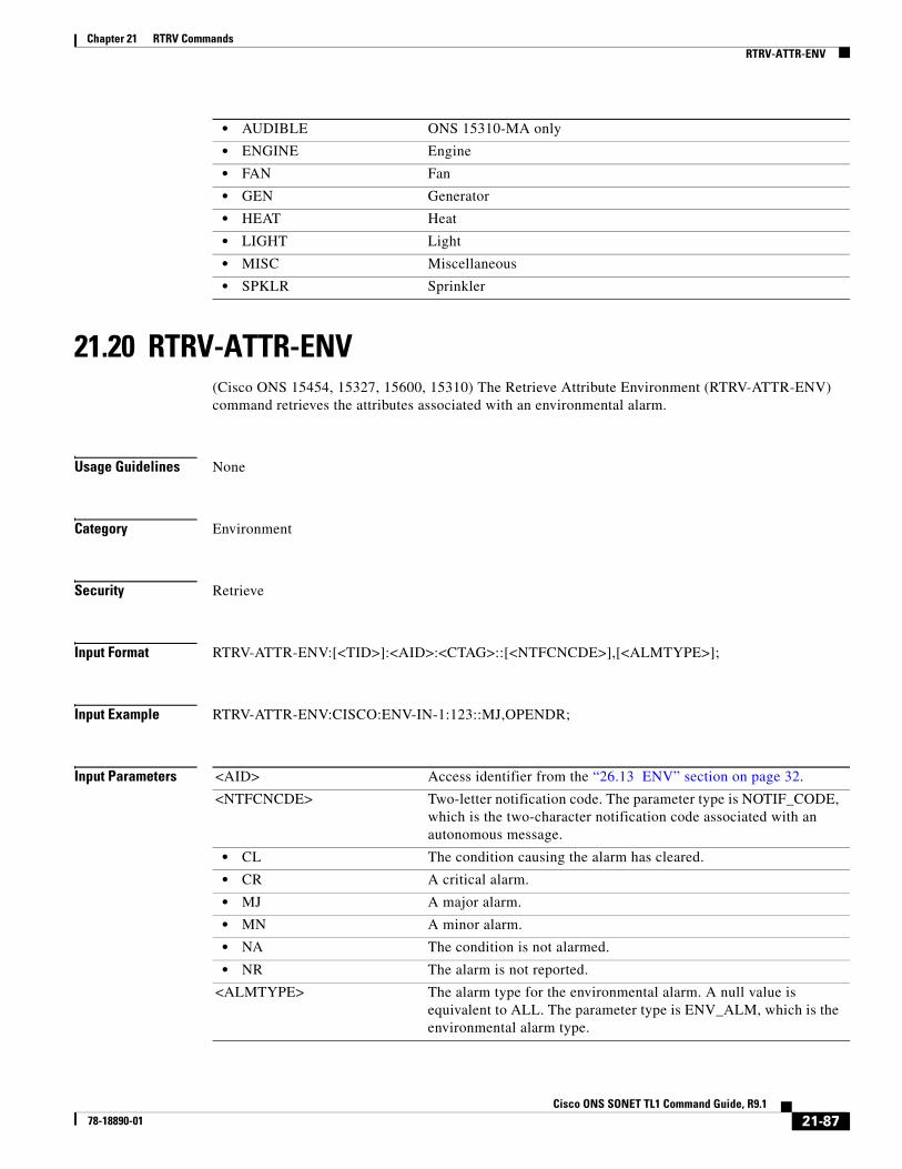
Chapter 21 RTRV CommandsRTRV-ATTR-ENV
21.20 RTRV-ATTR-ENV(Cisco ONS 15454, 15327, 15600, 15310) The Retrieve Attribute Environment (RTRV-ATTR-ENV) command retrieves the attributes associated with an environmental alarm.
Usage Guidelines None
Category Environment
Security Retrieve
Input Format RTRV-ATTR-ENV:[<TID>]:<AID>:<CTAG>::[<NTFCNCDE>],[<ALMTYPE>];
Input Example RTRV-ATTR-ENV:CISCO:ENV-IN-1:123::MJ,OPENDR;
Input Parameters
• AUDIBLE ONS 15310-MA only
• ENGINE Engine
• FAN Fan
• GEN Generator
• HEAT Heat
• LIGHT Light
• MISC Miscellaneous
• SPKLR Sprinkler
<AID> Access identifier from the “26.13 ENV” section on page 32.
<NTFCNCDE> Two-letter notification code. The parameter type is NOTIF_CODE, which is the two-character notification code associated with an autonomous message.
• CL The condition causing the alarm has cleared.
• CR A critical alarm.
• MJ A major alarm.
• MN A minor alarm.
• NA The condition is not alarmed.
• NR The alarm is not reported.
<ALMTYPE> The alarm type for the environmental alarm. A null value is equivalent to ALL. The parameter type is ENV_ALM, which is the environmental alarm type.
21-87Cisco ONS SONET TL1 Command Guide, R9.1
78-18890-01

Chapter 21 RTRV CommandsRTRV-ATTR-ENV
• AIRCOMPR Air compressor failure
• AIRCOND Air conditioning failure
• AIRDRYR Air dryer failure
• BATDSCHRG Battery discharging
• BATTERY Battery failure
• CLFAN Cooling fan failure
• CPMAJOR Centralized power major failure
• CPMINOR Centralized power minor failure
• ENGINE Engine failure
• ENGOPRG Engine operating
• ENGTRANS Standby engine transfer
• EXPLGS Explosive gas
• FIRDETR Fire detector failure
• FIRE Fire
• FLOOD Flood
• FUELLEAK Fuel leak
• FUSE Fuse failure
• GASALARM Explosive gas, toxic gas, ventilation fail, or gas monitor fail
• HATCH CEV hatch fail
• GEN Generator failure
• HIAIR High airflow
• HIHUM High humidity
• HITEMP High temperature
• HIWTR High water
• INTRUDER Intrusion
• LEVELCON Level converter
• LVDADSL Secondary ADSL low voltage disconnect
• LVDBYPAS Low voltage disconnect bypass
• LWBATVG Low battery voltage
• LWFUEL Low fuel
• LWHUM Low humidity
• LWPRES Low cable pressure
• LWTEMP Low temperature
• LWWTR Low water
• MISC Miscellaneous
• OPENDR Open door
• POWER Commercial power failure
• PUMP Pump failure
• PWR-48 48 V power supply failure
• PWR-139 –139 V power converter
• PWR-190 –190 V power converter
21-88Cisco ONS SONET TL1 Command Guide, R9.1
78-18890-01

Chapter 21 RTRV CommandsRTRV-ATTR-ENV
Output Format SID DATE TIMEM CTAG COMPLD “<AID>:[<NTFCNCDE>],[<ALMTYPE>],[<DESC>]”;
Output Example TID-000 1998-06-20 14:30:00M 001 COMPLD “ENV-IN-1:MJ,OPENDR,\“OPEN DOOR\””;
Output Parameters
• PWRMJ Power supply major
• PWRMN Power supply minor
• RECT Rectifier failure
• RECTHI Rectifier high voltage
• RECTLO Rectifier low voltage
• RINGGENMJ Ringing generator major
• RINGGENMN Ringing generator minor
• RTACADSL AC or AC/rectifier power fail ADSL equipment
• RTACCRIT AC or AC/rectifier power fail DCL equipment critical site
• RTACPWR AC or AC/rectifier power fail DCL equipment
• RTACPWRENG Commercial AC fail, site equipped with standby engine
• RTBAYPWR AC power loss distributed power RT bay
• RTRVENG Retrieve standby engine, commercial AC restored
• SMOKE Smoke
• TEMP High-low temperature
• TOXICGAS Toxic gas
• TREPEATER T-repeater shelf
• VENTN Ventilation system failure
<AID> Access identifier from the “26.13 ENV” section on page 32.
<NTFCNCDE> (Optional) Two-letter notification code. The parameter type is NOTIF_CODE, which is the two-character notification code associated with an autonomous message.
• CL The condition causing the alarm has cleared.
• CR A critical alarm.
• MJ A major alarm.
• MN A minor alarm.
• NA The condition is not alarmed.
• NR The alarm is not reported.
<ALMTYPE> (Optional) The alarm type for the environmental alarm. The parameter type is ENV_ALM, which is the environmental alarm type.
21-89Cisco ONS SONET TL1 Command Guide, R9.1
78-18890-01

Chapter 21 RTRV CommandsRTRV-ATTR-ENV
• AIRCOMPR Air compressor failure
• AIRCOND Air conditioning failure
• AIRDRYR Air dryer failure
• BATDSCHRG Battery discharging
• BATTERY Battery failure
• CLFAN Cooling fan failure
• CPMAJOR Centralized power major failure
• CPMINOR Centralized power minor failure
• ENGINE Engine failure
• ENGOPRG Engine operating
• ENGTRANS Standby engine transfer
• EXPLGS Explosive gas
• FIRDETR Fire detector failure
• FIRE Fire
• FLOOD Flood
• FUELLEAK Fuel leak
• FUSE Fuse failure
• GASALARM Explosive gas, toxic gas, ventilation fail or gas monitor fail
• HATCH CEV hatch fail
• GEN Generator failure
• HIAIR High airflow
• HIHUM High humidity
• HITEMP High temperature
• HIWTR High water
• INTRUDER Intrusion
• LEVELCON Level converter
• LVDADSL Secondary ADSL low voltage disconnect
• LVDBYPAS Low voltage disconnect bypass
• LWBATVG Low battery voltage
• LWFUEL Low fuel
• LWHUM Low humidity
• LWPRES Low cable pressure
• LWTEMP Low temperature
• LWWTR Low water
• MISC Miscellaneous
• OPENDR Open door
• POWER Commercial power failure
• PUMP Pump failure
• PWR-48 48V power supply failure
• PWR-139 –139 V power converter
• PWR-190 –190 V power converter
21-90Cisco ONS SONET TL1 Command Guide, R9.1
78-18890-01

Chapter 21 RTRV CommandsRTRV-AUDIT-LOG
21.21 RTRV-AUDIT-LOG(Cisco ONS 15454, 15327, 15600, 15310) The Retrieve Audit Log (RTRV-AUDIT-LOG) command retrieves the contents of the audit log stored in the NE. Audit records contain information for user operations such as login, logout, change of provisioning parameters and other changes a user might make when connected to the NE. Audit records do not store operations related to parameter retrieval.
Usage Guidelines None
Category Log
Security Superuser
Input Format RTRV-AUDIT-LOG:[<TID>]::<CTAG>;
Input Example RTRV-AUDIT-LOG:::1;
• PWRMJ Power supply major
• PWRMN Power supply minor
• RECT Rectifier failure
• RECTHI Rectifier high voltage
• RECTLO Rectifier low voltage
• RINGGENMJ Ringing generator major
• RINGGENMN Ringing generator minor
• RTACADSL AC or AC/rectifier power fail ADSL equipment
• RTACCRIT AC or AC/rectifier power fail DCL equipment critical site
• RTACPWR AC or AC/rectifier power fail DCL equipment
• RTACPWRENG Commercial AC fail, site equipped with standby engine
• RTBAYPWR AC power loss distributed power RT bay
• RTRVENG Retrieve standby engine, commercial AC restored
• SMOKE Smoke
• TEMP High-low temperature
• TOXICGAS Toxic gas
• TREPEATER T-repeater shelf
• VENTN Ventilation system failure
<DESC> (Optional) Alarm description. DESC is a string.
21-91Cisco ONS SONET TL1 Command Guide, R9.1
78-18890-01

Chapter 21 RTRV CommandsRTRV-BFDLPM-<MOD2>
Input Parameters None that require description
Output Format SID DATE TIMEM CTAG COMPLD “ <ENTRYNUM>,<OCRDAT>,<OCRTM>,<TASKID>,<TXSTATUS>,<DESCRIPTION>”;
Output Example TID-000 1998-06-20 14:30:00M 001 COMPLD “ 17172,2004-10-05,09-52-44, TPROVMGR,COMPLD, \17172,2004-10-05,09-52-44, TPROVMGR,COMPLD,\"DESCRIPTION\””;
Output Parameters
21.22 RTRV-BFDLPM-<MOD2>(Cisco ONS 15454) The Retrieve BFDL Performance Monitoring (DS1, T1) command retrieves the BFDL (enhanced 24-hour ES, UAS, BES, CSS, and LOFC) performance monitoring parameters and applies to the DS3XM-12 card DS1 under BFDL mode. This command returns the current 15-minute and current 24-hour BFDL performance monitoring (PM) parameters and the 96 15-minute history requested type PM parameters.
Usage Guidelines For example, the following input:
RTRV-BFDLPM-DS1::DS1-14-1-1:1:::REQTYPE=ENH-24HR-ES;
Will retrieve the following output:
DS1-14-1-1:ES,30,CURR-15MIN-INV DS1-14-1-1:UAS,40,CURR-15MIN-INV DS1-14-1-1:BES,50,CURR-15MIN-INV DS1-14-1-1:SES,60,CURR-15MIN-INV DS1-14-1-1:CSS,70,CURR-15MIN-INV DS1-14-1-1:LOFC,80,CURR-15MIN-INV DS1-14-1-1:ES,30,CURR-24HR-INV DS1-14-1-1:UAS,40,CURR-24HR-INV
<ENTRYNUM> Entry number. ENTRYNUM is an integer.
<OCRDAT> Date when the specific event or violation occurred, MM-DD.
<OCRTM> Time when the specific event or violation occurred, HH-MM-SS.
<TASKID> Task ID. TASKID is a string.
<TXSTATUS> Parameter type is TX_STATUS, which indicates the status of the transferred file.
• COMPLD The file transmission is completed.
• IP The file transmission is in process.
• START The file transmission is started.
<DESCRIPTION> Description of event. Description format varies depending on the event and can include parameters used during the event. DESCRIPTION is a string.
21-92Cisco ONS SONET TL1 Command Guide, R9.1
78-18890-01

Chapter 21 RTRV CommandsRTRV-BFDLPM-<MOD2>
DS1-14-1-1:BES,50,CURR-24HR-INV DS1-14-1-1:SES,60,CURR-24HR-INV DS1-14-1-1:CSS,70,CURR-24HR-INV DS1-14-1-1:LOFC,80,CURR-24HR-INV DS1-14-1-1:ES,30,1-15MIN-INV DS1-14-1-1:ES,40,2-15MIN-INVDS1-14-1-1:ES,50,3-15MIN-INVDS1-14-1-1:ES,80,96-15MIN-INV
Sending this command with a REQTYPE of ENH-24HR-CSS-AND-LOFC will retrieve 96 15-minute PM parameters for both CSS and LOFC. The command is applied on the DS3XM-12 DS1 under BFDL mode, ESF frame format, C-BIT IS port with an IS VT circuit configuration.
Category Performance
Security Retrieve
Input Format RTRV-BFDLPM-<MOD2>:[<TID>]:<AID>:<CTAG>:::REQTYPE=<REQTYPE>;
Input Example RTRV-BFDLPM-DS1:TID:DS1-14-1-1:123:::REQTYPE=ENH-24HR-ES;
Input Parameters
Output Format SID DATE TIMEM CTAG COMPLD “<AID>:<MONTYPE>,<MONVAL>,<BUCKET>”;
Output Example TID-000 1998-06-20 14:30:00M 001 COMPLD “DS1-14-1-1:ES,55,CURR-15MIN-INV”;
Output Parameters
<AID> Access identifier from the “26.12 DS1” section on page 32.
<REQTYPE> Indicates requested BFDL PM type. Must not be null. The parameter type is REQTYPE, which is the requested PM type.
• ENH-24HR-BES The enhanced 24-hour BES performance data
• ENH-24HR-CSS-AND-LOFC The enhanced 24-hour CSS-AND-LOFC performance data
• ENH-24HR-ES The enhanced 24-hour ES performance data
• ENH-24HR-SES The enhanced 24-hour SES performance data
• ENH-24HR-UAS The enhanced 24-hour UAS performance data
<AID> Access identifier from the “26.12 DS1” section on page 32.
21-93Cisco ONS SONET TL1 Command Guide, R9.1
78-18890-01
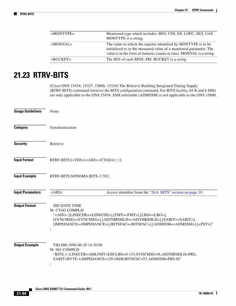
Chapter 21 RTRV CommandsRTRV-BITS
21.23 RTRV-BITS(Cisco ONS 15454, 15327, 15600, 15310) The Retrieve Building Integrated Timing Supply (RTRV-BITS) command retrieves the BITS configuration command. For BITS facility, 64 K and 6 MHz are only applicable to the ONS 15454. SSM selectable (ADMSSM) is not applicable to the ONS 15600.
Usage Guidelines None
Category Synchronization
Security Retrieve
Input Format RTRV-BITS:[<TID>]:<AID>:<CTAG>[::::];
Input Example RTRV-BITS:SONOMA:BITS-1:782;
Input Parameters
Output Format SID DATE TIMEM CTAG COMPLD “<AID>::[LINECDE=<LINECDE>],[FMT=<FMT>],[LBO=<LBO>], [SYNCMSG=<SYNCMSG>],[AISTHRSHLD=<AISTHRSHLD>],[SABIT=<SABIT>], [IMPEDANCE=<IMPEDANCE>],[BITSFAC=<BITSFAC>],[ADMSSM=<ADMSSM>]:[<PST>]”;
Output Example TID-000 1998-06-20 14:30:00M 001 COMPLD “BITS-1::LINECDE=AMI,FMT=ESF,LBO=0-133,SYNCMSG=N,AISTHRSHLD=PRS, SABIT=BYTE-4,IMPEDANCE=120-OHM,BITSFAC=T1,ADMSSM=PRS:IS”;
<MONTYPE> Monitored type which includes: BES, CSS, ES, LOFC, SES, UAS. MONTYPE is a string.
<MONVAL> The value to which the register identified by MONTYPE is to be initialized to or the measured value of a monitored parameter. The value is in the form of numeric counts or rates. MONVAL is a string.
<BUCKET> The BIN of each BFDL PM. BUCKET is a string.
<AID> Access identifier from the “26.6 BITS” section on page 19.
21-94Cisco ONS SONET TL1 Command Guide, R9.1
78-18890-01

Chapter 21 RTRV CommandsRTRV-BITS
Output Parameters <AID> Access identifier from the “26.6 BITS” section on page 19
<LINECDE> (Optional) Line code. The parameter type is LINE_CODE.
• AMI Line code value is AMI.
• B8ZS Line code value is B8ZS (binary eight-zero substitution).
<FMT> (Optional) Digital signal frame format. The parameter type is FRAME_FORMAT, which is the frame format for a T1 port.
• D4 Frame format is D4.
• ESF Frame format is ESF.
• UNFRAMED Frame format is unframed.
<LBO> (Optional) Line buildout settings. BITS line buildout. Default value is 0 to 133. LBP is an integer. The parameter type is BITS_LineBuildOut, which is the BITS line buildout.
• 0–133 BITS line buildout range is 0–133.
• 134–266 BITS line buildout range is 134–266.
• 267–399 BITS line buildout range is 267–399.
• 400–533 BITS line buildout range is 400–533.
• 534–655 BITS line buildout range is 534–655.
<SYNCMSG> Indicates if the BITS facility supports synchronization status message. Default is Y. The parameter type is EXT_RING, which indicates if the ring supports the extended K1/K2/K3 protocol.
• N The ring does not support the extended K1/K2/K3 protocol.
• Y The ring does support the extended K1/K2/K3 protocol.
<AISTHRSHLD> (Optional) Alarm indication signal threshold. The parameter type is SYNC_CLOCK_REF_QUALITY_LEVEL, which is the clock source quality level for SONET.
• DUS Do Not Use For Synchronization
• PRS Primary Reference Source, Stratum 1 Traceable
• RES Reserved For Network Synchronization Use
• SMC SONET Minimum Clock Traceable
• ST2 Stratum 2 Traceable
• ST3 Stratum 3 Traceable
• ST3E Stratum 3E Traceable
• ST4 Stratum 4 Traceable
• STU Synchronized, Traceability Unknown
• TNC Transit Node Clock (2nd Generation Only)
<SABIT> (Optional) When the frame format selection is E1, SABIT is the BIT used to receive and transmit the SSM. The parameter type is SABITS (SA BITS).
• BYTE-4 SABIT is BYTE-4.
• BYTE-5 SABIT is BYTE-5.
• BYTE-6 SABIT is BYTE-6.
• BYTE-7 SABIT is BYTE-7.
• BYTE-8 SABIT is BYTE-8.
21-95Cisco ONS SONET TL1 Command Guide, R9.1
78-18890-01
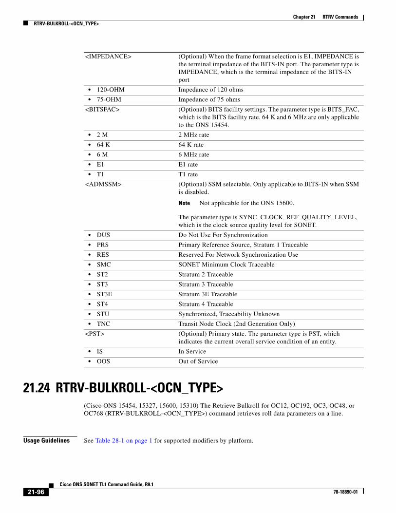
Chapter 21 RTRV CommandsRTRV-BULKROLL-<OCN_TYPE>
21.24 RTRV-BULKROLL-<OCN_TYPE>(Cisco ONS 15454, 15327, 15600, 15310) The Retrieve Bulkroll for OC12, OC192, OC3, OC48, or OC768 (RTRV-BULKROLL-<OCN_TYPE>) command retrieves roll data parameters on a line.
Usage Guidelines See Table 28-1 on page 1 for supported modifiers by platform.
<IMPEDANCE> (Optional) When the frame format selection is E1, IMPEDANCE is the terminal impedance of the BITS-IN port. The parameter type is IMPEDANCE, which is the terminal impedance of the BITS-IN port
• 120-OHM Impedance of 120 ohms
• 75-OHM Impedance of 75 ohms
<BITSFAC> (Optional) BITS facility settings. The parameter type is BITS_FAC, which is the BITS facility rate. 64 K and 6 MHz are only applicable to the ONS 15454.
• 2 M 2 MHz rate
• 64 K 64 K rate
• 6 M 6 MHz rate
• E1 E1 rate
• T1 T1 rate
<ADMSSM> (Optional) SSM selectable. Only applicable to BITS-IN when SSM is disabled.
Note Not applicable for the ONS 15600.
The parameter type is SYNC_CLOCK_REF_QUALITY_LEVEL, which is the clock source quality level for SONET.
• DUS Do Not Use For Synchronization
• PRS Primary Reference Source, Stratum 1 Traceable
• RES Reserved For Network Synchronization Use
• SMC SONET Minimum Clock Traceable
• ST2 Stratum 2 Traceable
• ST3 Stratum 3 Traceable
• ST3E Stratum 3E Traceable
• ST4 Stratum 4 Traceable
• STU Synchronized, Traceability Unknown
• TNC Transit Node Clock (2nd Generation Only)
<PST> (Optional) Primary state. The parameter type is PST, which indicates the current overall service condition of an entity.
• IS In Service
• OOS Out of Service
21-96Cisco ONS SONET TL1 Command Guide, R9.1
78-18890-01

Chapter 21 RTRV CommandsRTRV-BULKROLL-<OCN_TYPE>
Category Bridge and Roll
Security Provisioning
Input Format RTRV-BULKROLL-<OCN_TYPE>:[<TID>]:<SRC>:<CTAG>;
Input Example RTRV-BULKROLL-OC12:CISCO:FAC-3-1:1;
Input Parameters
Output Format SID DATE TIMEM CTAG COMPLD “<FROM>:RFROM=<RFROM>,RTO=<RTO>,[RMODE=<RMODE>],VLDSIG=<VLDSIG>”;
Output Example TID-000 1998-06-20 14:30:00M 001 COMPLD “STS-3-1-1:RFROM=STS-3-1-1,RTO=STS-5-1-1,RMODE=AUTO,VLDSIG=Y”;
Output Parameters
<SRC> Source AID from the “26.15 FACILITY” section on page 35.
<FROM> One of the end points. Access identifier from the “26.15 FACILITY” section on page 35 for line level rolling and bulk rolling.
<RFROM> The termination point of the existing cross-connect that is to be rolled. The AID is from the “26.11 CrossConnectId1” section on page 26 (except VCM and FACILITY).
<RTO> The termination point that will become a leg of the new cross-connection. The AID is from the “26.11 CrossConnectId1” section on page 26 (except VCM and FACILITY).
<RMODE> (Optional) The rolling mode of operation. The parameter type is RMODE, which specifies the roll mode.
• AUTO Automatic. When a valid signal is available, the roll under AUTO mode will automatically delete the previous end-point.
• MAN Manual. Enter the corresponding delete roll/bulkroll command to delete the previous end-point.
• MAN Manual
• MAN-RESTART Manual Restart for Test
<VLDSIG> (Optional) The rolling mode of operation. The parameter type is ON_OFF (disable or enable an attribute).
21-97Cisco ONS SONET TL1 Command Guide, R9.1
78-18890-01

Chapter 21 RTRV CommandsRTRV-BULKROLL-<OCN_TYPE>
• N Disable an attribute.
• Y Enable an attribute.
21-98Cisco ONS SONET TL1 Command Guide, R9.1
78-18890-01

Chapter 21 RTRV CommandsRTRV-BWP-ETH
21.25 RTRV-BWP-ETH(Cisco ONS 15454)
This command is used to retrieve a BandWidth Profile entry in BWP DB. The BWP DB is a collection of BWP used in a Network Element.
Usage Guidelines The “ALL” AID is supported by this command.
If the AID is invalid, an IIAC (Invalid AID) error message is returned.
Category Ethernet
Security Retrieve
Input Format RTRV-BWP-ETH:[<TID>]:<AID>:<CTAG>[::::];
Input Example RTRV-BWP-ETH:ROCKS:BWP-10000:1;
Input Parameter
Output Format SID DATE TIME
M CTAG COMPLD
"<AID>::[NAME=<NAME>],[CIR=<CIR>],[CBS=<CBS>],[PBS=<PBS>],[PIR=<PIR>],[CFMSTATE=<CFM_STATE>]:";
;
Output Example TID-000 1998-06-20 14:30:00
Table 21-1 Input Parameter Support
Parameter DescriptionCisco ONS 15454
Cisco ONS 15600
Cisco ONS 15310 MA
<AID> This AID is used to access BWP. Y N N
• BWP-ALL All aid for BWP. Y N N
• BWP-{1-10000} Single AID for BWP. The valid identifiers ranges from 1 to 10000.
Y N N
21-99Cisco ONS SONET TL1 Command Guide, R9.1
78-18890-01
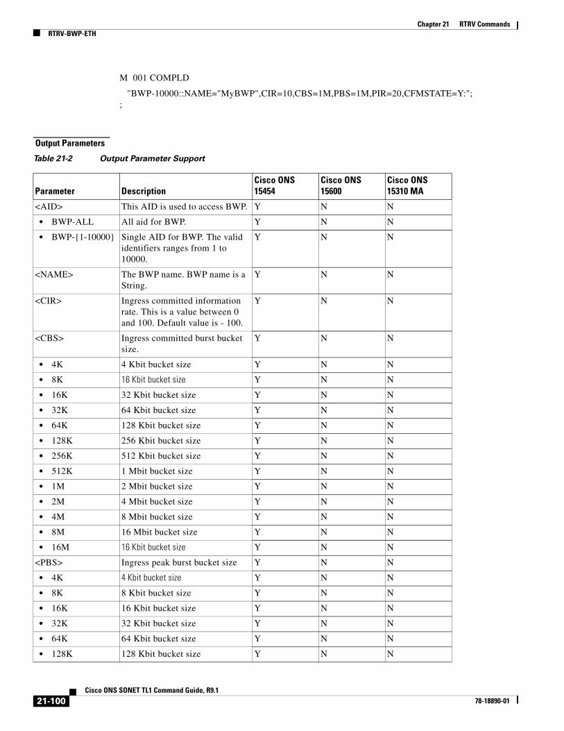
Chapter 21 RTRV CommandsRTRV-BWP-ETH
M 001 COMPLD
"BWP-10000::NAME="MyBWP",CIR=10,CBS=1M,PBS=1M,PIR=20,CFMSTATE=Y:"; ;
Output Parameters
Table 21-2 Output Parameter Support
Parameter DescriptionCisco ONS 15454
Cisco ONS 15600
Cisco ONS 15310 MA
<AID> This AID is used to access BWP. Y N N
• BWP-ALL All aid for BWP. Y N N
• BWP-{1-10000} Single AID for BWP. The valid identifiers ranges from 1 to 10000.
Y N N
<NAME> The BWP name. BWP name is a String.
Y N N
<CIR> Ingress committed information rate. This is a value between 0 and 100. Default value is - 100.
Y N N
<CBS> Ingress committed burst bucket size.
Y N N
• 4K 4 Kbit bucket size Y N N
• 8K 16 Kbit bucket size Y N N
• 16K 32 Kbit bucket size Y N N
• 32K 64 Kbit bucket size Y N N
• 64K 128 Kbit bucket size Y N N
• 128K 256 Kbit bucket size Y N N
• 256K 512 Kbit bucket size Y N N
• 512K 1 Mbit bucket size Y N N
• 1M 2 Mbit bucket size Y N N
• 2M 4 Mbit bucket size Y N N
• 4M 8 Mbit bucket size Y N N
• 8M 16 Mbit bucket size Y N N
• 16M 16 Kbit bucket size Y N N
<PBS> Ingress peak burst bucket size Y N N
• 4K 4 Kbit bucket size Y N N
• 8K 8 Kbit bucket size Y N N
• 16K 16 Kbit bucket size Y N N
• 32K 32 Kbit bucket size Y N N
• 64K 64 Kbit bucket size Y N N
• 128K 128 Kbit bucket size Y N N
21-100Cisco ONS SONET TL1 Command Guide, R9.1
78-18890-01

Chapter 21 RTRV CommandsRTRV-CMD-SECU
21.26 RTRV-CMD-SECU(Cisco ONS 15454, 15327, 15600, 15310) The Retrieve Command Security (RTRV-CMD-SECU) command retrieves the current command security level of the command specified in the AID field.
Usage Guidelines None
Category Security
Security Superuser
Input Format RTRV-CMD-SECU:[<TID>]:<AID>:<CTAG>;
Input Example RTRV-CMD-SECU::INIT-REG:1;
Input Parameters
• 256K 256 Kbit bucket size Y N N
• 512K 512 Kbit bucket size Y N N
• 1M 1 Mbit bucket size Y N N
• 2M 2 Mbit bucket size Y N N
• 4M 4 Mbit bucket size Y N N
• 8M 8 Mbit bucket size Y N N
• 16M 16 Mbit bucket size Y N N
<PIR> Peak information rate. This is a value between 0 and 100. Default value is - 100.
Y N N
<CFMSTATE> Link Integrity status Y N N
• Y Enabled Y N N
• N Disabled Y N N
Table 21-2 Output Parameter Support
Parameter DescriptionCisco ONS 15454
Cisco ONS 15600
Cisco ONS 15310 MA
<AID> Access identifier string. Identifies the entity in the NE to which the command pertains. It is the command verb along with verb modifier(s), as it currently exists. It can be a single command or a block of commands, where the block might include all commands. Only INIT-REG will be supported. String.
21-101Cisco ONS SONET TL1 Command Guide, R9.1
78-18890-01

Chapter 21 RTRV CommandsRTRV-COND-<MOD2ALM>
Output Format SID DATE TIMEM CTAG COMPLD “<AID>:<CAP>”;
Output Example TID-000 1998-06-20 14:30:00M 001 COMPLD “INIT-REG:PROV”;
Output Parameters
21.27 RTRV-COND-<MOD2ALM>(Cisco ONS 15454, 15327, 15600, 15310) The Retrieve Condition for 10GFC, 10GIGE, 40GIGE, 1GFC, 1GFICON, 2GFC, 2GFICON, 4GFC, 4GFICON, 5GIB, 8GFC, DS1, DS3I, DVBASI, E1, E100, E1000, E3, E4, EC1, ETH, FSTE, G1000, ETH, GFPOS, GIGE, ILK, ISCCOMPAT, ISC1, ISC3PEER2R, ISC3PEER1G, ISC3PEER2G, OC12, OC192, OC3, OC48, OC768, OCH, OMS, OTS, OTU2, OTU3, POS, RPRIF, STM1, STM4, STM16, STM64, STM1E, STS1, STS12C, STS18C, STS192C, STS24C, STS36C, STS3C, STS48C, STS96C, STS6C, STS9C, T1, T3, UDCDCC, UDCF, VC11, VC12, VC3, VC4, VC4-2c,VC4-3c, VC4-4c, VC4-8c, VC4-16c, VC4-64c, VCG, VT1, VT2, WLEN, or RPRIF(RTRV-COND-<MOD2ALM>) command retrieves the current standing condition and state associated with an entity.
Usage Guidelines See Table 28-1 on page 1 for supported modifiers by platform.
Category Fault
Security Retrieve
Input Format RTRV-COND-<MOD2ALM>:[<TID>]:<AID>:<CTAG>::[<TYPEREQ>],[<LOCN>],[<DIRN>];
Input Example RTRV-COND-RPRIF:DXT:RPRIF-2-0:229::FORCE-REQ;
<AID> (Optional) Access identifier. It can be a single command or a block of commands, where the block can include all commands. Only INIT-REG is supported. AID is a string.
<CAP> Command access privilege. The parameter type is PRIVILEGE, which is the security level.
• PROV Provisioning security level
• SUPER Superuser security level
21-102Cisco ONS SONET TL1 Command Guide, R9.1
78-18890-01

Chapter 21 RTRV CommandsRTRV-COND-<MOD2ALM>
Input Parameters
Output Format SID DATE TIMEM CTAG COMPLD “<AID>,[<AIDTYPE>]:[<NTFCNCDE>],<TYPEREP>,[<SRVEFF>],[<OCRDAT>], [<OCRTM>],<LOCN>,<DIRECTION>,[<DESC>]”;
Output Example TID-000 1998-06-20 14:30:00M 001 COMPLD “RPRIF-2-0,T3:MJ,FORCE-REQ,SA,01-01,16-00-20,NEND,RCV,\"FORCED SWITCH REQUEST\"";
Output Parameters
<AID> Access identifier from the “26.1 ALL” section on page 1.
<TYPEREQ> The type of condition to be retrieved. A null value is equivalent to ALL. The parameter type is CONDITION, which is any problem detected on an ONS 15454, ONS 15310-CL, ONS 15310-MA or ONS 15600 shelf, whether or not the problem is reported (that is, whether or not it generates a trouble notification). Reported conditions include alarms, NA conditions, and NR conditions. See Chapter 27, “Conditions” for a list of conditions.
<LOCN> Location associated with a particular command. Identifies the location from which the PM mode is to be retrieved. The parameter type is LOCATION, which is the location where the action is to take place.
• FEND Action occurs on the far end of the facility.
• NEND Action occurs on the near end of the facility.
<DIRN> The PM count retrieval direction. The parameter type is DIRECTION, which is the transmit and receive directions.
• BTH Both transmit and receive directions
• RCV Receive direction only
<AID> Access identifier from the “26.1 ALL” section on page 1.
<AIDTYPE> (Optional) Type of access identifier. Specifies the type of facility, link or other addressable entity targeted by the message. The parameter type is MOD2ALM, which is the alarm type.
• 1GFC 1-Gigabit Fibre Channel payload
• 1GFICON 1-Gigabit fiber connectivity payload
• 1GISC3 1-Gigabit ISC3 compatible
• 2GFC 2-Gigabit Fibre Channel payload
• 2GFICON 2-Gigabit fiber connectivity payload
• 4GFC 4-Gigabit Fibre Channel payload
• 4GFICON 4-Gigabit fiber connectivity payload
• 40GIGE 40-Gigabit Ethernet
• 5GIB 5Gbps InfiniBand payload
21-103Cisco ONS SONET TL1 Command Guide, R9.1
78-18890-01

Chapter 21 RTRV CommandsRTRV-COND-<MOD2ALM>
• 8GFC 8-Gigabit Fibre Channel payload
• CLNT Client facility for MXP/TXP cards
• DS1 DS1 alarm
• DS3I DS3I alarm
• DVBASI Digital Video Broadband Asynchronous Serial Interface (DVBASI) payload
• E100 E100 alarm
• E1000 E1000 alarm
• EC1 EC1 alarm
• FSTE Fast Ethernet Port alarm
• G1000 G1000 alarm
• GFPOS Generic framing protocol over packet over SONET virtual port alarm
• GIGE Gigabit Ethernet port alarm
• ISC1 InterSystem Channel, a protocol defined by IBM (ISC1) payload
• ISC3PEER1G 1-Gigabit ISC3 Peer
• ISC3PEER2G 2 Gbps ISC3 Peer
• ISC3PEER2R 1 Gbps or 2 Gbps ISC3 peer used in transparent (2R) mode
• ISCCOMPAT 1 Gbps ISC1, ISC2, and ISC3 compatibility
• OC3 OC3 alarm
• OC12 OC12 alarm
• OC48 OC48 alarm
• OC192 OC192 alarm
• OC768 OC768 alarm
• OCH Optical channel
• OCHTERM OCH termination
• OMS Optical Multiplex Section
• OTS Optical Transport Section
• OTU3 Optical Transport Unit Level 3
• POS POS port alarm
• STS1 STS1 alarm
• STS3C STS3c alarm
• STS6C STS6c alarm
• STS9C STS9c alarm
• STS18C STS18c alarm
• STS12C STS12c alarm
• STS24C STS24c alarm
• STS36C STS36c alarm
• STS48C STS48c alarm
• STS192C STS192c alarm
• T1 T1 alarm
• T3 T3 alarm
21-104Cisco ONS SONET TL1 Command Guide, R9.1
78-18890-01

Chapter 21 RTRV CommandsRTRV-COND-<MOD2ALM>
• UDCDCC UDC-DCC alarm
• UDCF UCD-F alarm
• VCG Virtual concatenation group alarm
• VT1 VT1 alarm
• VT2 VT2 alarm
• WLEN Wavelength path provisioning
<NTFCNCDE> (Optional) Two-letter notification code. The parameter type is NOTIF_CODE, which is the two-character notification code associated with an autonomous message.
• CL The condition causing the alarm has cleared.
• CR A critical alarm.
• MJ A major alarm.
• MN A minor alarm.
• NA The condition is not alarmed.
• NR The alarm is not reported.
<TYPEREP> The condition itself. The parameter type is CONDITION, which is any problem detected on an ONS 15454, ONS 15310-CL, ONS 15310-MA, or ONS 15600 shelf, whether or not the problem is reported (that is, whether or not it generates a trouble notification). Reported conditions include alarms, NA conditions, and NR conditions. See Chapter 27, “Conditions” for a list of conditions.
<SRVEFF> (Optional) The effect on service caused by the standing alarm or condition The parameter type is SERV_EFF, which is the effect of the alarm on service.
• NSA The condition is non-service affecting.
• SA The condition is service affecting.
<OCRDAT> (Optional) Date when the specific event or violation occurred, MM-DD.
<OCRTM> (Optional) Time when the specific event or violation occurred, HH-MM-SS.
<LOCN> Location associated with a particular command. Identifies the location from which the PM mode is to be retrieved. The parameter type is LOCATION, which is the location where the action is to take place.
• FEND Action occurs on the far end of the facility.
• NEND Action occurs on the near end of the facility.
<DIRECTION> The PM count retrieval direction. The parameter type is DIRECTION, which is the transmit and receive directions.
• BTH Both transmit and receive directions
• RCV Receive direction only
<DESC> (Optional) Condition description. DESC is a string.
21-105Cisco ONS SONET TL1 Command Guide, R9.1
78-18890-01

Chapter 21 RTRV CommandsRTRV-COND-ALL
21.28 RTRV-COND-ALL(Cisco ONS 15454, 15327, 15600, 15310) The Retrieve Condition All (RTRV-CON-ALL) command retrieves the current standing condition for all entities.
Usage Guidelines According to Telcordia GR-833, the RTRV-COND-ALL command only reports EQPT, COM, and rr (T1, T3, OCn, EC1, STSn, VT1, DS1, E100, E1000, G1000, ML-Series, TXP and MXP) alarms.
This command does not return all conditions that are returned by other, more specific RTRV-COND commands; RTRV-COND-ALL returns a subset of these conditions. Telcordia GR-253-CORE, Section 6.2.1.8.4 states a retrieval that returns ALL conditions from a node (RTRV-COND-ALL) must omit any conditions that are “same root cause” as other raised conditions. The section also states any retrieval of a subset of the conditions from a node, regardless of how the subsetting occurs, should not omit these “same root cause” conditions.
RTRV-COND-STS1, for example, includes “same root cause” conditions in the set it returns and RTRV-COND-ALL does not.
To retrieve all the NE conditions, issue all of the following commands:
RTRV-COND-ALLRTRV-COND-ENVRTRV-COND-BITSRTRV-COND-SYNCN
Category Fault
Security Retrieve
Input Format RTRV-COND-ALL:[<TID>]:[<AID>]:<CTAG>::[<TYPEREQ>],[<LOCN>],[<DIRN>];
Input Example RTRV-COND-ALL:DXT:ALL:229::FORCE-REQ;
Input Parameters <AID> Access identifier from the “26.1 ALL” section on page 1. String. A null value is equivalent to ALL.
<TYPEREQ> The type of condition to be retrieved. A null value is equivalent to ALL. The parameter type is CONDITION, which is any problem detected on an ONS 15454, ONS 15310-CL, ONS 15310-MA or ONS 15600 shelf, whether or not the problem is reported (that is, whether or not it generates a trouble notification). Reported conditions include alarms, NA conditions, and NR conditions. See Chapter 27, “Conditions” for a list of conditions.
21-106Cisco ONS SONET TL1 Command Guide, R9.1
78-18890-01

Chapter 21 RTRV CommandsRTRV-COND-ALL
Output Format SID DATE TIMEM CTAG COMPLD “<AID>,[<AIDTYPE>]:[<NTFCNCDE>],<TYPEREP>,[<SRVEFF>],[<OCRDAT>], [<OCRTM>],<LOCN>,<DIRECTION>,[<DESC>]”;
Output Example TID-000 1998-06-20 14:30:00M 001 COMPLD “RPRIF-2-0,T3:MJ,FORCE-REQ,SA,01-01,16-00-20,NEND,RCV,\"FORCED SWITCH REQUEST\"";
Output Parameters
<LOCN> Location associated with a particular command. Identifies the location from which the PM mode is to be retrieved. The parameter type is LOCATION, which is the location where the action is to take place.
• FEND Action occurs on the far end of the facility.
• NEND Action occurs on the near end of the facility.
<DIRN> The PM count retrieval direction. The parameter type is DIRECTION, which is the transmit and receive directions.
• BTH Both transmit and receive directions
• RCV Receive direction only
<AID> Access identifier from the “26.1 ALL” section on page 1 that has an alarm condition.
<AIDTYPE> (Optional) Type of access identifier. Specifies the type of facility, link or other addressable entity targeted by the message. The parameter type is MOD2B, which is the alarm type.
• 1GFC 1-Gigabit Fibre Channel payload
• 1GFICON 1-Gigabit fiber connectivity payload
• 2GFC 2-Gigabit Fibre Channel payload
• 2GFICON 2-Gigabit fiber connectivity payload
• 4GFC 4-Gigabit Fibre Channel payload
• 4GFICON 4-Gigabit fiber connectivity payload
• 40-GiGE 40-Gigabit Ethernet
• 5GIB 5Gbps InfiniBand payload
• 8GFC 8-Gigabit Fibre Channel payload
• BITS BITS alarm
• CLNT Client facility for MXP/TXP cards
• COM Common alarm
• DS1 DS1 alarm
• DS3I DS3I alarm
21-107Cisco ONS SONET TL1 Command Guide, R9.1
78-18890-01
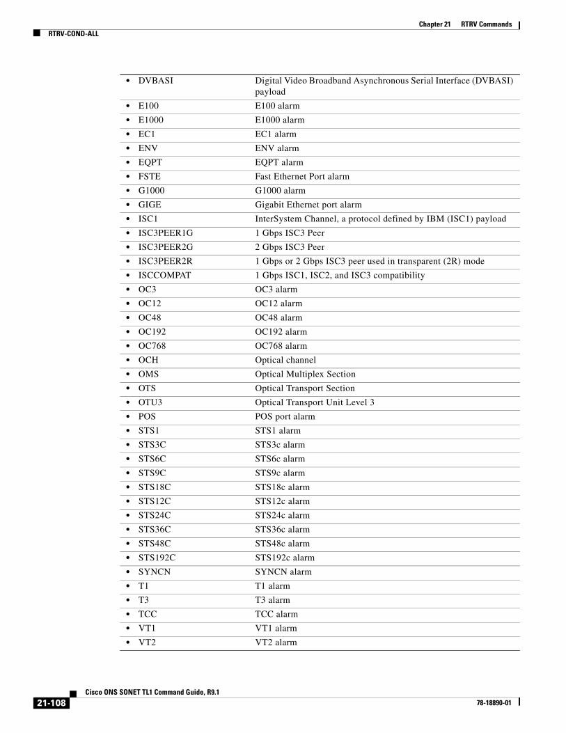
Chapter 21 RTRV CommandsRTRV-COND-ALL
• DVBASI Digital Video Broadband Asynchronous Serial Interface (DVBASI) payload
• E100 E100 alarm
• E1000 E1000 alarm
• EC1 EC1 alarm
• ENV ENV alarm
• EQPT EQPT alarm
• FSTE Fast Ethernet Port alarm
• G1000 G1000 alarm
• GIGE Gigabit Ethernet port alarm
• ISC1 InterSystem Channel, a protocol defined by IBM (ISC1) payload
• ISC3PEER1G 1 Gbps ISC3 Peer
• ISC3PEER2G 2 Gbps ISC3 Peer
• ISC3PEER2R 1 Gbps or 2 Gbps ISC3 peer used in transparent (2R) mode
• ISCCOMPAT 1 Gbps ISC1, ISC2, and ISC3 compatibility
• OC3 OC3 alarm
• OC12 OC12 alarm
• OC48 OC48 alarm
• OC192 OC192 alarm
• OC768 OC768 alarm
• OCH Optical channel
• OMS Optical Multiplex Section
• OTS Optical Transport Section
• OTU3 Optical Transport Unit Level 3
• POS POS port alarm
• STS1 STS1 alarm
• STS3C STS3c alarm
• STS6C STS6c alarm
• STS9C STS9c alarm
• STS18C STS18c alarm
• STS12C STS12c alarm
• STS24C STS24c alarm
• STS36C STS36c alarm
• STS48C STS48c alarm
• STS192C STS192c alarm
• SYNCN SYNCN alarm
• T1 T1 alarm
• T3 T3 alarm
• TCC TCC alarm
• VT1 VT1 alarm
• VT2 VT2 alarm
21-108Cisco ONS SONET TL1 Command Guide, R9.1
78-18890-01

Chapter 21 RTRV CommandsRTRV-COND-BITS
21.29 RTRV-COND-BITS(Cisco ONS 15454, 15327, 15600, 15310) The Retrieve Condition Building Integrated Timing Supply (RTRV-COND-BITS) command retrieves the standing conditions on BITS.
Usage Guidelines None
<NTFCNCDE> (Optional) Two-letter notification code. The parameter type is NOTIF_CODE, which is the two-character notification code associated with an autonomous message.
• CL The condition causing the alarm has cleared.
• CR A critical alarm.
• MJ A major alarm.
• MN A minor alarm.
• NA The condition is not alarmed.
• NR The alarm is not reported.
<TYPEREP> The type of condition to be retrieved. The parameter type is CONDITION, which is any problem detected on an ONS 15454, ONS 15310-CL, ONS 15310-MA, or ONS 15600 shelf, whether or not the problem is reported (that is, whether or not it generates a trouble notification). Reported conditions include alarms, NA conditions, and NR conditions. See Chapter 27, “Conditions” for a list of conditions.
<SRVEFF> (Optional) The effect on service caused by the standing alarm or condition The parameter type is SERV_EFF, which is the effect of the alarm on service.
• NSA The condition is non-service affecting.
• SA The condition is service affecting.
<OCRDAT> (Optional) Date when the specific event or violation occurred, MM-DD.
<OCRTM> (Optional) Time when the specific event or violation occurred, HH-MM-SS.
<LOCN> Location associated with a particular command. Identifies the location from which the PM mode is to be retrieved. The parameter type is LOCATION, which is the location where the action is to take place.
• FEND Action occurs on the far end of the facility.
• NEND Action occurs on the near end of the facility.
<DIRECTION> The PM count retrieval direction. The parameter type is DIRECTION, which is the transmit and receive directions.
• BTH Both transmit and receive directions
• RCV Receive direction only
<DESC> (Optional) Condition description. DESC is a string.
21-109Cisco ONS SONET TL1 Command Guide, R9.1
78-18890-01
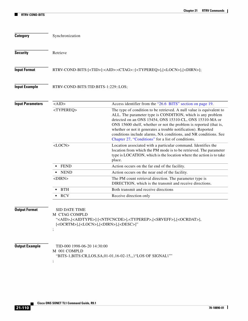
Chapter 21 RTRV CommandsRTRV-COND-BITS
Category Synchronization
Security Retrieve
Input Format RTRV-COND-BITS:[<TID>]:<AID>:<CTAG>::[<TYPEREQ>],[<LOCN>],[<DIRN>];
Input Example RTRV-COND-BITS:TID:BITS-1:229::LOS;
Input Parameters
Output Format SID DATE TIMEM CTAG COMPLD “<AID>,[<AIDTYPE>]:[<NTFCNCDE>],<TYPEREP>,[<SRVEFF>],[<OCRDAT>], [<OCRTM>],[<LOCN>],[<DIRN>],[<DESC>]”;
Output Example TID-000 1998-06-20 14:30:00M 001 COMPLD “BITS-1,BITS:CR,LOS,SA,01-01,16-02-15,,,\“LOS OF SIGNAL\””;
<AID> Access identifier from the “26.6 BITS” section on page 19.
<TYPEREQ> The type of condition to be retrieved. A null value is equivalent to ALL. The parameter type is CONDITION, which is any problem detected on an ONS 15454, ONS 15310-CL, ONS 15310-MA or ONS 15600 shelf, whether or not the problem is reported (that is, whether or not it generates a trouble notification). Reported conditions include alarms, NA conditions, and NR conditions. See Chapter 27, “Conditions” for a list of conditions.
<LOCN> Location associated with a particular command. Identifies the location from which the PM mode is to be retrieved. The parameter type is LOCATION, which is the location where the action is to take place.
• FEND Action occurs on the far end of the facility.
• NEND Action occurs on the near end of the facility.
<DIRN> The PM count retrieval direction. The parameter type is DIRECTION, which is the transmit and receive directions.
• BTH Both transmit and receive directions
• RCV Receive direction only
21-110Cisco ONS SONET TL1 Command Guide, R9.1
78-18890-01

Chapter 21 RTRV CommandsRTRV-COND-BITS
Output Parameters <AID> Access identifier from the “26.6 BITS” section on page 19 that has an alarm condition.
<AIDTYPE> (Optional) Type of access identifier. Specifies the type of facility, link or other addressable entity targeted by the message. The parameter type is MOD2B, which is the alarm type.
• 1GFC 1-Gigabit Fibre Channel payload
• 1GFICON 1-Gigabit fiber connectivity payload
• 2GFC 2-Gigabit Fibre Channel payload
• 2GFICON 2-Gigabit fiber connectivity payload
• 4GFC 4-Gigabit Fibre Channel payload
• 4GFICON 4-Gigabit fiber connectivity payload
• 40GIGE 40-Gigabit Ethernet
• 5GIB 5Gbps InfiniBand payload
• 8GFC 8-Gigabit Fibre Channel payload
• BITS BITS alarm
• CLNT Client facility for MXP/TXP cards
• COM Common alarm
• DS1 DS1 alarm
• DS3I DS2I alarm
• E100 E100 alarm
• E1000 E1000 alarm
• EC1 EC1 alarm
• ENV ENV alarm
• EQPT EQPT alarm
• FSTE Fast Ethernet Port alarm
• G1000 G1000 alarm
• GIGE Gigabit Ethernet port alarm
• ISC3PEER1G 1 Gbps ISC3 Peer
• ISC3PEER2G 2 Gbps ISC3 Peer
• ISC3PEER2R 1 Gbps or 2 Gbps ISC3 peer used in transparent (2R) mode
• ISCCOMPAT 1 Gbps ISC1, ISC2, and ISC3 compatibility
• OC3 OC3 alarm
• OC12 OC12 alarm
• OC48 OC48 alarm
• OC192 OC192 alarm
• OC768 OC768 alarm
• OCH Optical channel
• OMS Optical Multiplex Section
• OTS Optical Transport Section
• OTU3 Optical Transport Unit Level 3
• POS POS port alarm
• STS1 STS1 alarm
21-111Cisco ONS SONET TL1 Command Guide, R9.1
78-18890-01

Chapter 21 RTRV CommandsRTRV-COND-BITS
• STS3C STS3c alarm
• STS6C STS6c alarm
• STS9C STS9c alarm
• STS18C STS18c alarm
• STS12C STS12c alarm
• STS24C STS24c alarm
• STS36C STS36c alarm
• STS48C STS48c alarm
• STS192C STS192c alarm
• SYNCN SYNCN alarm
• T1 T1 alarm
• T3 T3 alarm
• TCC TCC alarm
• VT1 VT1 alarm
• VT2 VT2 alarm
<NTFCNCDE> (Optional) Two-letter notification code. The parameter type is NOTIF_CODE, which is the two-character notification code associated with an autonomous message.
• CL The condition causing the alarm has cleared.
• CR A critical alarm.
• MJ A major alarm.
• MN A minor alarm.
• NA The condition is not alarmed.
• NR The alarm is not reported.
<TYPEREP> The type of condition to be retrieved. The parameter type is CONDITION, which is any problem detected on an ONS 15454, ONS 15310-CL, ONS 15310-MA, or ONS 15600 shelf, whether or not the problem is reported (that is, whether or not it generates a trouble notification). Reported conditions include alarms, NA conditions, and NR conditions. See Chapter 27, “Conditions” for a list of conditions.
<SRVEFF> (Optional) The effect on service caused by the standing alarm or condition. The parameter type is SERV_EFF, which is the effect of the alarm on service.
• NSA The condition is non-service affecting.
• SA The condition is service affecting.
<OCRDAT> (Optional) Date when the specific event or violation occurred, MM-DD.
<OCRTM> (Optional) Time when the specific event or violation occurred, HH-MM-SS.
21-112Cisco ONS SONET TL1 Command Guide, R9.1
78-18890-01

Chapter 21 RTRV CommandsRTRV-COND-ENV
21.30 RTRV-COND-ENV(Cisco ONS 15454, 15327, 15600, 15310) The Retrieve Environmental Condition (RTRV-COND-ENV) command retrieves the environmental conditions.
Usage Guidelines None
Category Environment
Security Retrieve
Input Format RTRV-COND-ENV:[<TID>]:<AID>:<CTAG>::[<NTFCNCDE>],[<ALMTYPE>],[<LOCN>],[<DIRN>];
Input Example RTRV-COND-ENV:CISCO:ENV-IN-1:123::MJ,OPENDR;
Input Parameters
<LOCN> Location associated with a particular command. Identifies the location from which the PM mode is to be retrieved. The parameter type is LOCATION, which is the location where the action is to take place.
• FEND Action occurs on the far end of the facility.
• NEND Action occurs on the near end of the facility.
<DIRN> The PM count retrieval direction. The parameter type is DIRECTION, which is the transmit and receive directions.
• BTH Both transmit and receive directions
• RCV Receive direction only
<DESC> (Optional) Condition description. DESC is a string.
<AID> Access identifier from the “26.13 ENV” section on page 32.
Note For RTRV-ALM-ENV, only ENV-IN-{1-4} is a valid AID for ONS 15454. ENV-OUT-{1,6} is not a valid AID for RTRV-ALM-ENV.
<NTFCNCDE> Two-letter notification code. A null value is equivalent to ALL. The parameter type is NOTIF_CODE, which is the two-character notification code associated with an autonomous message.
• CL The condition causing the alarm has cleared.
• CR A critical alarm.
• MJ A major alarm.
21-113Cisco ONS SONET TL1 Command Guide, R9.1
78-18890-01
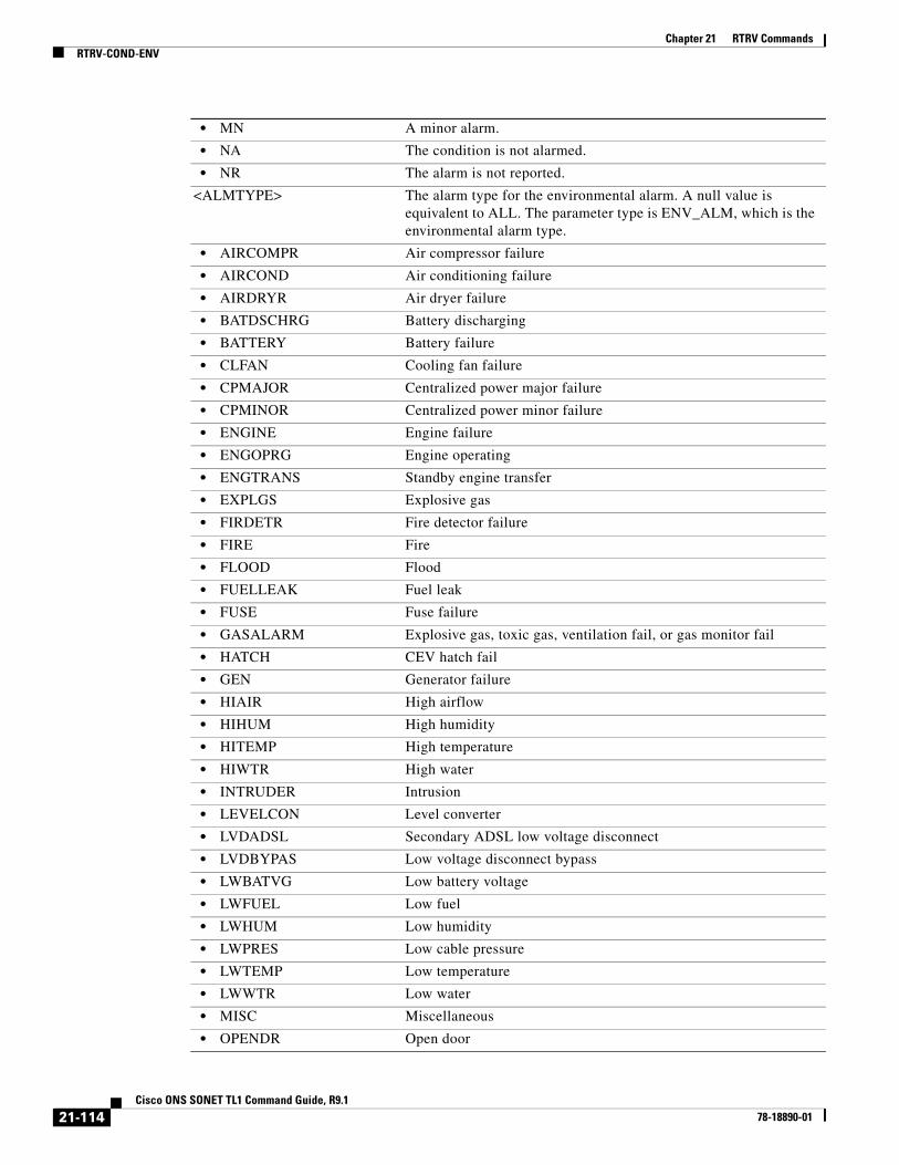
Chapter 21 RTRV CommandsRTRV-COND-ENV
• MN A minor alarm.
• NA The condition is not alarmed.
• NR The alarm is not reported.
<ALMTYPE> The alarm type for the environmental alarm. A null value is equivalent to ALL. The parameter type is ENV_ALM, which is the environmental alarm type.
• AIRCOMPR Air compressor failure
• AIRCOND Air conditioning failure
• AIRDRYR Air dryer failure
• BATDSCHRG Battery discharging
• BATTERY Battery failure
• CLFAN Cooling fan failure
• CPMAJOR Centralized power major failure
• CPMINOR Centralized power minor failure
• ENGINE Engine failure
• ENGOPRG Engine operating
• ENGTRANS Standby engine transfer
• EXPLGS Explosive gas
• FIRDETR Fire detector failure
• FIRE Fire
• FLOOD Flood
• FUELLEAK Fuel leak
• FUSE Fuse failure
• GASALARM Explosive gas, toxic gas, ventilation fail, or gas monitor fail
• HATCH CEV hatch fail
• GEN Generator failure
• HIAIR High airflow
• HIHUM High humidity
• HITEMP High temperature
• HIWTR High water
• INTRUDER Intrusion
• LEVELCON Level converter
• LVDADSL Secondary ADSL low voltage disconnect
• LVDBYPAS Low voltage disconnect bypass
• LWBATVG Low battery voltage
• LWFUEL Low fuel
• LWHUM Low humidity
• LWPRES Low cable pressure
• LWTEMP Low temperature
• LWWTR Low water
• MISC Miscellaneous
• OPENDR Open door
21-114Cisco ONS SONET TL1 Command Guide, R9.1
78-18890-01
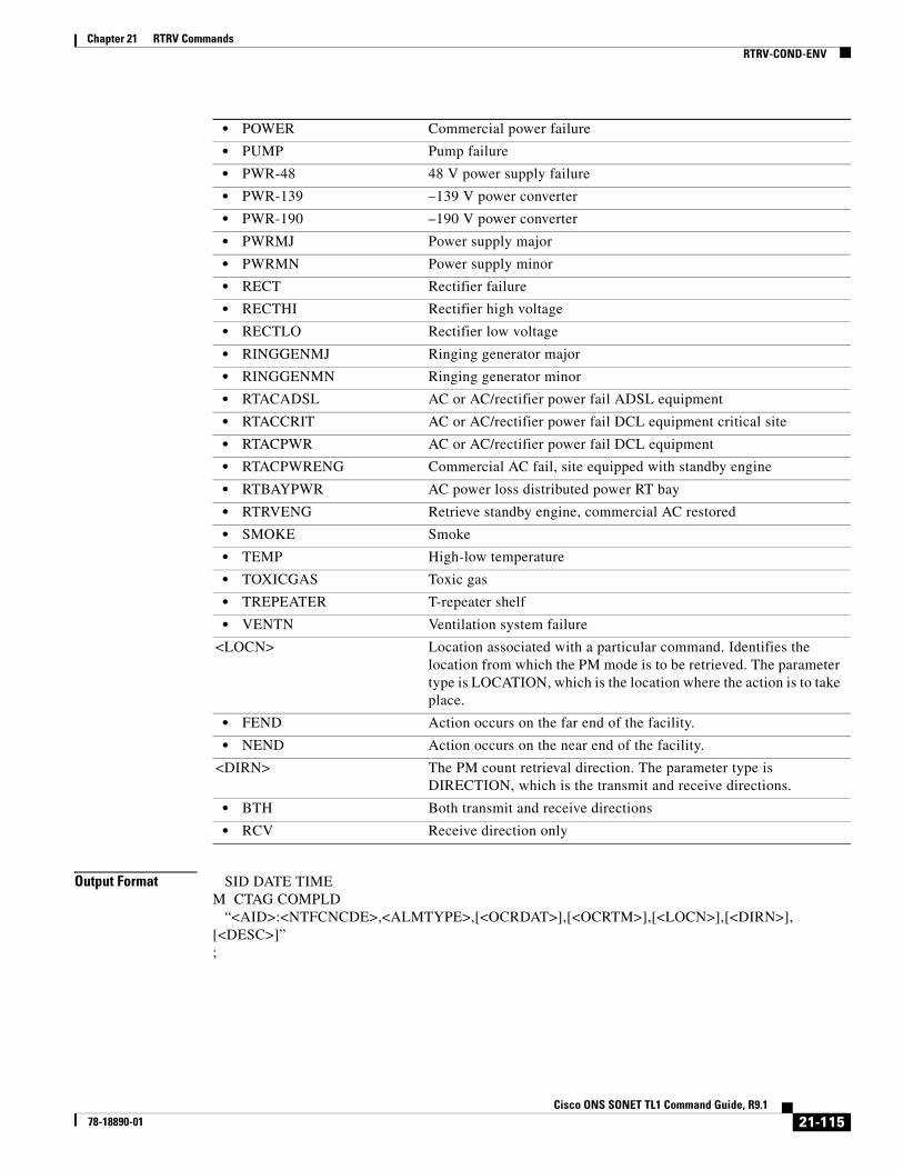
Chapter 21 RTRV CommandsRTRV-COND-ENV
Output Format SID DATE TIMEM CTAG COMPLD “<AID>:<NTFCNCDE>,<ALMTYPE>,[<OCRDAT>],[<OCRTM>],[<LOCN>],[<DIRN>],[<DESC>]”;
• POWER Commercial power failure
• PUMP Pump failure
• PWR-48 48 V power supply failure
• PWR-139 –139 V power converter
• PWR-190 –190 V power converter
• PWRMJ Power supply major
• PWRMN Power supply minor
• RECT Rectifier failure
• RECTHI Rectifier high voltage
• RECTLO Rectifier low voltage
• RINGGENMJ Ringing generator major
• RINGGENMN Ringing generator minor
• RTACADSL AC or AC/rectifier power fail ADSL equipment
• RTACCRIT AC or AC/rectifier power fail DCL equipment critical site
• RTACPWR AC or AC/rectifier power fail DCL equipment
• RTACPWRENG Commercial AC fail, site equipped with standby engine
• RTBAYPWR AC power loss distributed power RT bay
• RTRVENG Retrieve standby engine, commercial AC restored
• SMOKE Smoke
• TEMP High-low temperature
• TOXICGAS Toxic gas
• TREPEATER T-repeater shelf
• VENTN Ventilation system failure
<LOCN> Location associated with a particular command. Identifies the location from which the PM mode is to be retrieved. The parameter type is LOCATION, which is the location where the action is to take place.
• FEND Action occurs on the far end of the facility.
• NEND Action occurs on the near end of the facility.
<DIRN> The PM count retrieval direction. The parameter type is DIRECTION, which is the transmit and receive directions.
• BTH Both transmit and receive directions
• RCV Receive direction only
21-115Cisco ONS SONET TL1 Command Guide, R9.1
78-18890-01

Chapter 21 RTRV CommandsRTRV-COND-ENV
Output Example TID-000 1998-06-20 14:30:00M 001 COMPLD “ENV-IN-1:MJ,OPENDR,01-01,16-02-15,,,,\“OPEN DOOR\””;
Output Parameters <AID> Access identifier from the “26.13 ENV” section on page 32.
<NTFCNCDE> (Optional) Two-letter notification code. The parameter type is NOTIF_CODE, which is the two-character notification code associated with an autonomous message.
• CL The condition causing the alarm has cleared.
• CR A critical alarm.
• MJ A major alarm.
• MN A minor alarm.
• NA The condition is not alarmed.
• NR The alarm is not reported.
<ALMTYPE> The alarm type for the environmental alarm. The parameter type is ENV_ALM, which is the environmental alarm type.
• AIRCOMPR Air compressor failure
• AIRCOND Air conditioning failure
• AIRDRYR Air dryer failure
• BATDSCHRG Battery discharging
• BATTERY Battery failure
• CLFAN Cooling fan failure
• CPMAJOR Centralized power major failure
• CPMINOR Centralized power minor failure
• ENGINE Engine failure
• ENGOPRG Engine operating
• ENGTRANS Standby engine transfer
• EXPLGS Explosive gas
• FIRDETR Fire detector failure
• FIRE Fire
• FLOOD Flood
• FUELLEAK Fuel leak
• FUSE Fuse failure
• GASALARM Explosive gas, toxic gas, ventilation fail, or gas monitor fail
• HATCH CEV hatch fail
• GEN Generator failure
• HIAIR High airflow
• HIHUM High humidity
• HITEMP High temperature
• HIWTR High water
• INTRUDER Intrusion
21-116Cisco ONS SONET TL1 Command Guide, R9.1
78-18890-01

Chapter 21 RTRV CommandsRTRV-COND-ENV
• LEVELCON Level converter
• LVDADSL Secondary ADSL low voltage disconnect
• LVDBYPAS Low voltage disconnect bypass
• LWBATVG Low battery voltage
• LWFUEL Low fuel
• LWHUM Low humidity
• LWPRES Low cable pressure
• LWTEMP Low temperature
• LWWTR Low water
• MISC Miscellaneous
• OPENDR Open door
• POWER Commercial power failure
• PUMP Pump failure
• PWR-48 48V power supply failure
• PWR-139 –139 V power converter
• PWR-190 –190 V power converter
• PWRMJ Power supply major
• PWRMN Power supply minor
• RECT Rectifier failure
• RECTHI Rectifier high voltage
• RECTLO Rectifier low voltage
• RINGGENMJ Ringing generator major
• RINGGENMN Ringing generator minor
• RTACADSL AC or AC/rectifier power fail ADSL equipment
• RTACCRIT AC or AC/rectifier power fail DCL equipment critical site
• RTACPWR AC or AC/rectifier power fail DCL equipment
• RTACPWRENG Commercial AC fail, site equipped with standby engine
• RTBAYPWR AC power loss distributed power RT bay
• RTRVENG Retrieve standby engine, commercial AC restored
• SMOKE Smoke
• TEMP High-low temperature
• TOXICGAS Toxic gas
• TREPEATER T-repeater shelf
• VENTN Ventilation system failure
<OCRDAT> (Optional) Date when the specific event or violation occurred, MM-DD.
<OCRTM> (Optional) Time when the specific event or violation occurred, HH-MM-SS.
21-117Cisco ONS SONET TL1 Command Guide, R9.1
78-18890-01

Chapter 21 RTRV CommandsRTRV-COND-EQPT
21.31 RTRV-COND-EQPT(Cisco ONS 15454, 15327, 15600, 15310) The Retrieve Condition Equipment (RTRV-COND-EQPT) command retrieves the equipment conditions.
Usage Guidelines None
Category Equipment
Security Retrieve
Input Format RTRV-COND-EQPT:[<TID>]:<AID>:<CTAG>::[<TYPEREQ>],[<LOCN>],[<DIRN>];
Input Example RTRV-COND-EQPT:TID:SLOT-1:229::LOS;
Input Parameters
<LOCN> Location associated with a particular command. Identifies the location from which the PM mode is to be retrieved. The parameter type is LOCATION, which is the location where the action is to take place.
• FEND Action occurs on the far end of the facility.
• NEND Action occurs on the near end of the facility.
<DIRN> The PM count retrieval direction. The parameter type is DIRECTION, which is the transmit and receive directions.
• BTH Both transmit and receive directions
• RCV Receive direction only
<DESC> (Optional) Condition description. DESC is a string.
<AID> Access identifier from the “26.14 EQPT” section on page 33 that has an alarm condition.
<TYPEREQ> The type of condition to be retrieved. A null value is equivalent to ALL. The parameter type is CONDITION, which is any problem detected on an ONS 15454, ONS 15310-CL, ONS 15310-MA or ONS 15600 shelf, whether or not the problem is reported (that is, whether or not it generates a trouble notification). Reported conditions include alarms, NA conditions, and NR conditions. See Chapter 27, “Conditions” for a list of conditions.
21-118Cisco ONS SONET TL1 Command Guide, R9.1
78-18890-01

Chapter 21 RTRV CommandsRTRV-COND-EQPT
Output Format SID DATE TIMEM CTAG COMPLD “<AID>,[<AIDTYPE>]:[<NTFCNCDE>],<TYPEREP>,[<SRVEFF>],[<OCRDAT>], [<OCRTM>],[<LOCN>],[<DIRN>],[<DESC>]”;
Output Example TID-000 1998-06-20 14:30:00M 001 COMPLD “SLOT-1,EQPT:CR,LOS,SA,01-01,16-02-15,NEND,RCV,\"LOS OF SIGNAL\"”;
Output Parameters
<LOCN> Location associated with a particular command. Identifies the location from which the PM mode is to be retrieved. The parameter type is LOCATION, which is the location where the action is to take place.
• FEND Action occurs on the far end of the facility.
• NEND Action occurs on the near end of the facility.
<DIRN> The PM count retrieval direction. The parameter type is DIRECTION, which is the transmit and receive directions.
• BTH Both transmit and receive directions
• RCV Receive direction only
<AID> Access identifier from the “26.14 EQPT” section on page 33 that has an alarm condition.
<AIDTYPE> (Optional) Type of facility, link or other addressable entity targeted by the message. The parameter type is MOD2B, which is the alarm type.
• 1GFC 1-Gigabit Fibre Channel payload
• 1GFICON 1-Gigabit fiber connectivity payload
• 2GFC 2-Gigabit Fibre Channel payload
• 2GFICON 2-Gigabit fiber connectivity payload
• 4GFC 4-Gigabit Fibre Channel payload
• 4GFICON 4-Gigabit fiber connectivity payload
• 40GIGE 40-Gigabit Ethernet
• 5GIB 5Gbps InfiniBand payload
• 8GFC 8-Gigabit Fibre Channel payload
• BITS BITS alarm
• CLNT Client facility for MXP/TXP cards
• COM Common alarm
• DS1 DS1 alarm
• DS3I DS3I alarm
• E100 E100 alarm
• E1000 E1000 alarm
21-119Cisco ONS SONET TL1 Command Guide, R9.1
78-18890-01
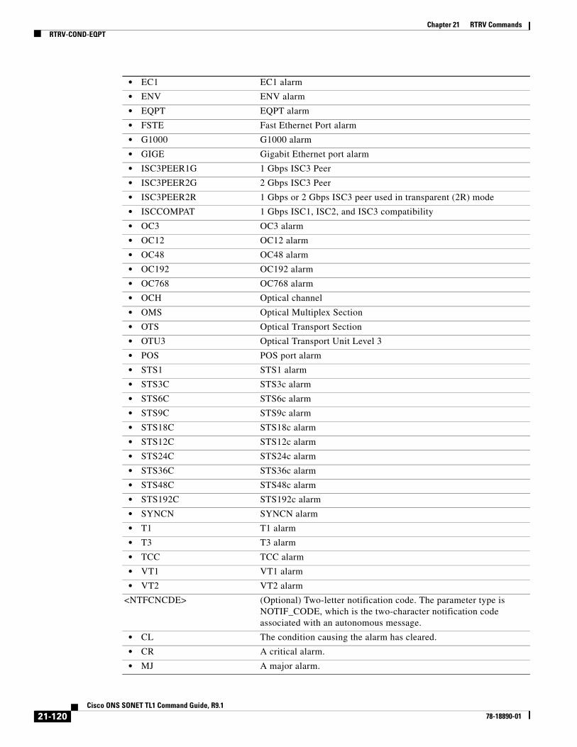
Chapter 21 RTRV CommandsRTRV-COND-EQPT
• EC1 EC1 alarm
• ENV ENV alarm
• EQPT EQPT alarm
• FSTE Fast Ethernet Port alarm
• G1000 G1000 alarm
• GIGE Gigabit Ethernet port alarm
• ISC3PEER1G 1 Gbps ISC3 Peer
• ISC3PEER2G 2 Gbps ISC3 Peer
• ISC3PEER2R 1 Gbps or 2 Gbps ISC3 peer used in transparent (2R) mode
• ISCCOMPAT 1 Gbps ISC1, ISC2, and ISC3 compatibility
• OC3 OC3 alarm
• OC12 OC12 alarm
• OC48 OC48 alarm
• OC192 OC192 alarm
• OC768 OC768 alarm
• OCH Optical channel
• OMS Optical Multiplex Section
• OTS Optical Transport Section
• OTU3 Optical Transport Unit Level 3
• POS POS port alarm
• STS1 STS1 alarm
• STS3C STS3c alarm
• STS6C STS6c alarm
• STS9C STS9c alarm
• STS18C STS18c alarm
• STS12C STS12c alarm
• STS24C STS24c alarm
• STS36C STS36c alarm
• STS48C STS48c alarm
• STS192C STS192c alarm
• SYNCN SYNCN alarm
• T1 T1 alarm
• T3 T3 alarm
• TCC TCC alarm
• VT1 VT1 alarm
• VT2 VT2 alarm
<NTFCNCDE> (Optional) Two-letter notification code. The parameter type is NOTIF_CODE, which is the two-character notification code associated with an autonomous message.
• CL The condition causing the alarm has cleared.
• CR A critical alarm.
• MJ A major alarm.
21-120Cisco ONS SONET TL1 Command Guide, R9.1
78-18890-01
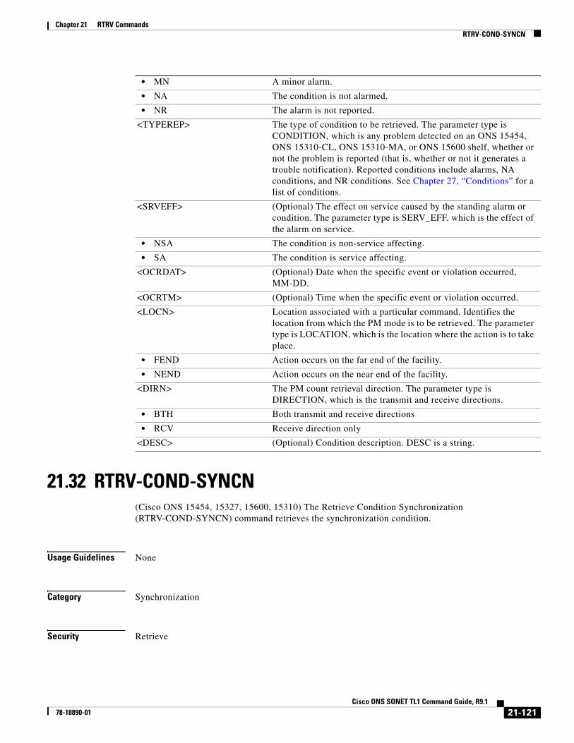
Chapter 21 RTRV CommandsRTRV-COND-SYNCN
21.32 RTRV-COND-SYNCN(Cisco ONS 15454, 15327, 15600, 15310) The Retrieve Condition Synchronization (RTRV-COND-SYNCN) command retrieves the synchronization condition.
Usage Guidelines None
Category Synchronization
Security Retrieve
• MN A minor alarm.
• NA The condition is not alarmed.
• NR The alarm is not reported.
<TYPEREP> The type of condition to be retrieved. The parameter type is CONDITION, which is any problem detected on an ONS 15454, ONS 15310-CL, ONS 15310-MA, or ONS 15600 shelf, whether or not the problem is reported (that is, whether or not it generates a trouble notification). Reported conditions include alarms, NA conditions, and NR conditions. See Chapter 27, “Conditions” for a list of conditions.
<SRVEFF> (Optional) The effect on service caused by the standing alarm or condition. The parameter type is SERV_EFF, which is the effect of the alarm on service.
• NSA The condition is non-service affecting.
• SA The condition is service affecting.
<OCRDAT> (Optional) Date when the specific event or violation occurred, MM-DD.
<OCRTM> (Optional) Time when the specific event or violation occurred.
<LOCN> Location associated with a particular command. Identifies the location from which the PM mode is to be retrieved. The parameter type is LOCATION, which is the location where the action is to take place.
• FEND Action occurs on the far end of the facility.
• NEND Action occurs on the near end of the facility.
<DIRN> The PM count retrieval direction. The parameter type is DIRECTION, which is the transmit and receive directions.
• BTH Both transmit and receive directions
• RCV Receive direction only
<DESC> (Optional) Condition description. DESC is a string.
21-121Cisco ONS SONET TL1 Command Guide, R9.1
78-18890-01
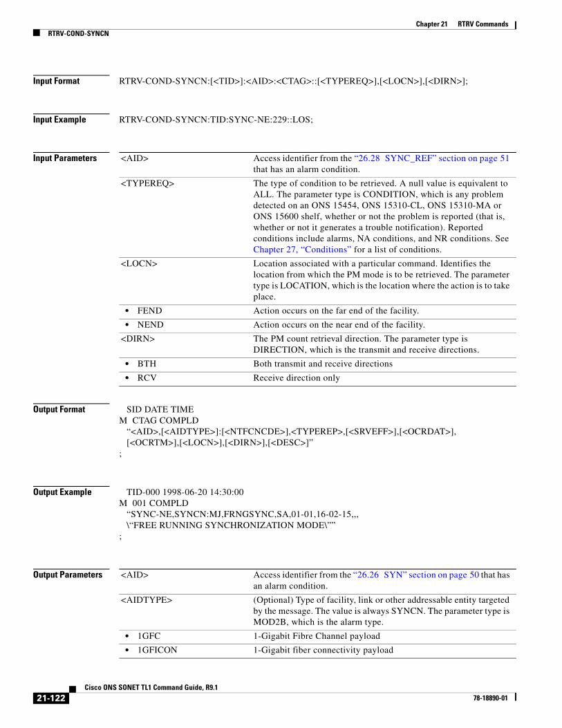
Chapter 21 RTRV CommandsRTRV-COND-SYNCN
Input Format RTRV-COND-SYNCN:[<TID>]:<AID>:<CTAG>::[<TYPEREQ>],[<LOCN>],[<DIRN>];
Input Example RTRV-COND-SYNCN:TID:SYNC-NE:229::LOS;
Input Parameters
Output Format SID DATE TIMEM CTAG COMPLD “<AID>,[<AIDTYPE>]:[<NTFCNCDE>],<TYPEREP>,[<SRVEFF>],[<OCRDAT>], [<OCRTM>],[<LOCN>],[<DIRN>],[<DESC>]”;
Output Example TID-000 1998-06-20 14:30:00M 001 COMPLD “SYNC-NE,SYNCN:MJ,FRNGSYNC,SA,01-01,16-02-15,,, \“FREE RUNNING SYNCHRONIZATION MODE\””;
Output Parameters
<AID> Access identifier from the “26.28 SYNC_REF” section on page 51 that has an alarm condition.
<TYPEREQ> The type of condition to be retrieved. A null value is equivalent to ALL. The parameter type is CONDITION, which is any problem detected on an ONS 15454, ONS 15310-CL, ONS 15310-MA or ONS 15600 shelf, whether or not the problem is reported (that is, whether or not it generates a trouble notification). Reported conditions include alarms, NA conditions, and NR conditions. See Chapter 27, “Conditions” for a list of conditions.
<LOCN> Location associated with a particular command. Identifies the location from which the PM mode is to be retrieved. The parameter type is LOCATION, which is the location where the action is to take place.
• FEND Action occurs on the far end of the facility.
• NEND Action occurs on the near end of the facility.
<DIRN> The PM count retrieval direction. The parameter type is DIRECTION, which is the transmit and receive directions.
• BTH Both transmit and receive directions
• RCV Receive direction only
<AID> Access identifier from the “26.26 SYN” section on page 50 that has an alarm condition.
<AIDTYPE> (Optional) Type of facility, link or other addressable entity targeted by the message. The value is always SYNCN. The parameter type is MOD2B, which is the alarm type.
• 1GFC 1-Gigabit Fibre Channel payload
• 1GFICON 1-Gigabit fiber connectivity payload
21-122Cisco ONS SONET TL1 Command Guide, R9.1
78-18890-01

Chapter 21 RTRV CommandsRTRV-COND-SYNCN
• 2GFC 2-Gigabit Fibre Channel payload
• 2GFICON 2-Gigabit fiber connectivity payload
• 4GFC 4-Gigabit Fibre Channel payload
• 4GFICON 4-Gigabit fiber connectivity payload
• 40GIGE 40-Gigabit Ethernet
• 5GIB 5Gbps InfiniBand payload
• 8GFC 8-Gigabit Fibre Channel payload
• BITS BITS alarm
• CLNT Client facility for MXP/TXP cards
• COM Common alarm
• DS1 DS1 alarm
• DS3I DS3I alarm
• E100 E100 alarm
• E1000 E1000 alarm
• EC1 EC1 alarm
• ENV ENV alarm
• EQPT EQPT alarm
• FSTE Fast Ethernet Port alarm
• G1000 G1000 alarm
• GIGE Gigabit Ethernet port alarm
• ISC3PEER1G 1 Gbps ISC3 Peer
• ISC3PEER2G 2 Gbps ISC3 Peer
• ISC3PEER2R 1 Gbps or 2 Gbps ISC3 peer used in transparent (2R) mode
• ISCCOMPAT 1 Gbps ISC1, ISC2, and ISC3 compatibility
• OC3 OC3 alarm
• OC12 OC12 alarm
• OC48 OC48 alarm
• OC192 OC192 alarm
• OC768 OC768 alarm
• OCH Optical channel
• OMS Optical Multiplex Section
• OTS Optical Transport Section
• OTU3 Optical Transport Unit Level 3
• POS POS port alarm
• STS1 STS1 alarm
• STS3C STS3c alarm
• STS6C STS6c alarm
• STS9C STS9c alarm
• STS18C STS18c alarm
• STS12C STS12c alarm
• STS24C STS24c alarm
21-123Cisco ONS SONET TL1 Command Guide, R9.1
78-18890-01

Chapter 21 RTRV CommandsRTRV-COND-SYNCN
• STS36C STS36c alarm
• STS48C STS48c alarm
• STS192C STS192c alarm
• SYNCN SYNCN alarm
• T1 T1 alarm
• T3 T3 alarm
• TCC TCC alarm
• VT1 VT1 alarm
• VT2 VT2 alarm
<NTFCNCDE> (Optional) Two-letter notification code. The parameter type is NOTIF_CODE, which is the two-character notification code associated with an autonomous message.
• CL The condition causing the alarm has cleared.
• CR A critical alarm.
• MJ A major alarm.
• MN A minor alarm.
• NA The condition is not alarmed.
• NR The alarm is not reported.
<TYPEREP> The type of condition to be retrieved. The parameter type is CONDITION, which is any problem detected on an ONS 15454, ONS 15310-CL, ONS 15310-MA, or ONS 15600 shelf, whether or not the problem is reported (that is, whether or not it generates a trouble notification). Reported conditions include alarms, NA conditions, and NR conditions. See Chapter 27, “Conditions” for a list of conditions.
<SRVEFF> (Optional) The effect on service caused by the standing alarm or condition. The parameter type is SERV_EFF, which is the effect of the alarm on service.
• NSA The condition is non-service affecting.
• SA The condition is service affecting.
<OCRDAT> (Optional) Date when the specific event or violation occurred, MM-DD.
<OCRTM> (Optional) Time when the specific event or violation occurred, HH-MM-SS.
<LOCN> Location associated with a particular command. Identifies the location from which the PM mode is to be retrieved. The parameter type is LOCATION, which is the location where the action is to take place.
• FEND Action occurs on the far end of the facility.
• NEND Action occurs on the near end of the facility.
<DIRN> The PM count retrieval direction. The parameter type is DIRECTION, which is the transmit and receive directions.
• BTH Both transmit and receive directions
• RCV Receive direction only
<DESC> (Optional) Condition description. DESC is a string.
21-124Cisco ONS SONET TL1 Command Guide, R9.1
78-18890-01

Chapter 21 RTRV CommandsRTRV-CONSOLE-PORT
21.33 RTRV-CONSOLE-PORT(Cisco ONS 15310-CL, Cisco ONS 15310-MA, and Cisco ONS 15454) The Retrieve Console Port (RTRV-CONSOLE-PORT) command retrieves the status of the console port from the ML-Series cards.
Usage Guidelines None
Category Security
Security Retrieve
Input Format RTRV-CONSOLE-PORT:[<TID>]:<AID>:<CTAG>;
Input Example RTRV-CONSOLE-PORT:CISCONODE:SLOT-2:123;
Input Parameters
Output Format SID DATE TIMEM CTAG COMPLD “<EQPT>:[PORT=<PORT>]”;
Output Example TID-000 1998-06-20 14:30:00M 001 COMPLD “SLOT-2:PORT=ENABLED”;
Output Parameters
<AID> Access identifier from the “26.14 EQPT” section on page 33.
<EQPT> Identifies the slot number for the data card. EQPT is a string.
<PORT> (Optional) Status of the console port on the data card. The parameter type is PORTSTAT, which is the status of the console port on the card.
• DISABLED The port is disabled.
• ENABLED The port is enabled.
21-125Cisco ONS SONET TL1 Command Guide, R9.1
78-18890-01

Chapter 21 RTRV CommandsRTRV-COS-ETH
21.34 RTRV-COS-ETH(Cisco ONS 15454) The Retrieve Cost of Service Ethernet (RTRV-COS-ETH) command retrieves the egress parameters of a CoS table associated to an L2 Ethernet port.
Usage Guidelines None
Category Ethernet
Security Provisioning
Input Format RTRV-COS-ETH:[<TID>]:<AID>:<CTAG>[::::];
Input Example RTRV-COS-ETH:TID:ETH-1-1-1:CTAG;
Input Parameters
Output Format SID DATE TIMEM CTAG COMPLD “<AID>::[QOSENABLED=<QOSENABLED>],[BW0=<BWO>],[WEIGHT0=<WEIGHT0>],[BW1=<BW1>],[WEIGHT1=<WEIGHT1>],[BW2=<BW2>],[WEIGHT2=<WEIGHT2>],[BW3=<BW3>],[WEIGHT3=<WEIGHT3>],[BW4=<BW4>],[WEIGHT4=<WEIGHT4>],[BW5=<BW5>],[WEIGHT5=<WEIGHT5>],[BW6=<BW6>],[WEIGHT6=<WEIGHT6>],[BW7=<BW7>],[WEIGHT7=<WEIGHT7>][:]”;
Output Example TID-000 1998-06-20 14:30:00M 001 COMPLD “ETH-5-1-1::QOSENABLED=Y,BW0=10,WEIGHT0=0,BW1=20,WEIGHT1=2,BW2=40,WEIGHT2=4,BW3=60,WEIGHT3=6,BW4=70,WEIGHT4=8,BW5=80,WEIGHT5=10,BW6=85,WEIGHT6=12,BW7=100,WEIGHT7=15:”;
Output Parameters
<AID> Ethernet AIDs are used to access L2 Ethernet ports. Access identifier from the “26.15 FACILITY” section on page 35.
<AID> Ethernet AIDs are used to access L2 Ethernet ports. Access identifier from the “26.15 FACILITY” section on page 35.
<QOSENABLED> Used to enable or disable the egress quality of service (QoS) policy of an L2 Ethernet port.
• N Disable the service
21-126Cisco ONS SONET TL1 Command Guide, R9.1
78-18890-01

Chapter 21 RTRV CommandsRTRV-CRS
21.35 RTRV-CRS(Cisco ONS 15454 and Cisco ONS 15600) The Retrieve Cross-Connect (RTRV-CRS) command retrieves all the cross-connections based on the required PATH types.
Usage Guidelines • This command retrieves all the STS and/or VT cross-connections on the NE, or on the specified shelf, card, or port.
• A NULL AID defaults to ALL (NE).
• A NULL PATH defaults to all the existing cross-connections.
• Both DRITYPE and DRINODE optional fields are available to support MSSPR-DRI. DRITYPE is applied only if the cross-connect is a drop-and-continue connection (1WAYDC or 2WAYDC), and defaults to SNCP for the DRI. DRINODE must be specified only if at least one end of the connection is on the MS-SPRing, and defaults to NA.
• CKTID is a string of ASCII characters. The maximum length of CKTID is 48. If the CKTID is EMPTY or NULL it will not appear.
• VC values in CRS_TYPE are not supported in this command.
• Y Enable the service
<BW0> Bandwidth percentage, a value between 0 and 100
<WEIGHT0> Value represents the weighted round-robin (WRR) weight associated to the CoS values. It is an integer value ranging between 0 and 15.
<BW1> Bandwidth percentage, a value between 0 and 100
<WEIGHT1> Value represents the WRR weight associated to the CoS values. It is an integer value ranging between 0 and 15.
<BW2> Bandwidth percentage, a value between 0 and 100
<WEIGHT2> Value represents the WRR weight associated to the CoS values. It is an integer value ranging between 0 and 15.
<BW3> Bandwidth percentage, a value between 0 and 100
<WEIGHT3> Value represents the WRR weight associated to the CoS values. It is an integer value ranging between 0 and 15.
<BW4> Bandwidth percentage, a value between 0 and 100
<WEIGHT4> Value represents the WRR weight associated to the CoS values. It is an integer value ranging between 0 and 15.
<BW5> Bandwidth percentage, a value between 0 and 100
<WEIGHT5> Value represents the WRR weight associated to the CoS values. It is an integer value ranging between 0 and 15.
<BW6> Bandwidth percentage, a value between 0 and 100
<WEIGHT6> Value represents the WRR weight associated to the CoS values. It is an integer value ranging between 0 and 15.
<BW7> Bandwidth percentage, a value between 0 and 100
<WEIGHT7> Value represents the WRR weight associated to the CoS values. It is an integer value ranging between 0 and 15.
21-127Cisco ONS SONET TL1 Command Guide, R9.1
78-18890-01

Chapter 21 RTRV CommandsRTRV-CRS
Category Cross Connections
Security Retrieve
Input Format RTRV-CRS:[<TID>]:[<AID>]:<CTAG>:::[CRSTYPE=<CRSTYPE>][:];
Input Example RTRV-CRS:CISCO:ALL:123:::CRSTYPE=STS;
Input Parameters <AID> Access identifier from the “26.11 CrossConnectId1” section on page 26 that can be EQPT, Facility, STS, VT, or ALL. The ALL AID defaults to NE, which means it reports all the existing cross-connections on the NE. A null value is equivalent to ALL.
<CRSTYPE> The cross-connection type. Defaults to all existing cross-connections. A null value is equivalent to ALL. The parameter type is PATH, which is the modifier for path commands.
Note The cross-connection type cannot be VT, if the AID specified is an STS AID.
• STS1 Synchronous transport signal/module level 1 (51.84 Mbps)
• STS3C Synchronous transport signal/module level 3 concatenated (155.52 Mbps)
• STS6C Synchronous transport signal/module level 6 (311.04 Mbps)
• STS9C Synchronous transport signal/module level 9 concatenated (466.56 Mbps)
• STS12C Synchronous transport signal/module level 12 concatenated (622.08 Mbps)
• STS18C Synchronous transport signal/module level 18 concatenated (933.12 Mbps)
• STS24C Synchronous transport signal/module level 24 concatenated (1244.16 Mbps)
• STS36C Synchronous transport signal/module level 36 concatenated (1866.24 Mbps)
• STS48C Synchronous transport signal/module level 48 concatenated (2488.32 Mbps)
• STS192C Synchronous transport signal/module level 192 concatenated (9953.28 Mbps)
• VT1 Virtual Tributary 1
• VT2 Virtual Tributary 2
21-128Cisco ONS SONET TL1 Command Guide, R9.1
78-18890-01

Chapter 21 RTRV CommandsRTRV-CRS
Output Format SID DATE TIMEM CTAG COMPLD “<SRC>,<DST>:<CCT>,<CRSTYPE>:[DRITYPE=<DRITYPE>],[DRINODE=<SYNCSW>], [CKTID=<CKTID>]:<PST_PSTQ>,[<SSTQ>]”;
Output Example TID-000 1998-06-20 14:30:00M 001 COMPLD “STS-5-1-2&STS-6-1-2,STS-12-1-2&STS-13-1-2:1WAYDC,STS1:DRITYPE=BLSR, DRINODE=PRI,CKTID=CKTID:OOS-AU,AINS”;
Output Parameters <SRC> Source access identifier from the “26.10 CrossConnectId” section on page 22. Indicates the source AID(s) of the cross-connection. SRC is listable.
<DST> Destination AID of the cross-connection from the “26.10 CrossConnectId” section on page 22. DST is listable.
<CCT> Type of connection. Used for specifying one or two-way connections. The parameter type is CCT, which is the type of cross-connect to be created.
• 1WAY A unidirectional connection from a source tributary to a destination tributary
• 1WAYDC Path Protection multicast drop with one-way continue
• 1WAYEN Path Protection multicast end node with one-way continue
• 1WAYMON A bidirectional connection between the two tributaries
Note In ONS 15454 Software Release 3.0 and later, 1WAYMON is not supported with TL1. However, it is still supported from Cisco Transport Controller (CTC). Using CTC, you can create 1WAYMON cross-connects that can be retrieved with TL1.
• 1WAYPCA A unidirectional connection from a source tributary to a destination tributary on the protection path/fiber
• 2WAY A bidirectional connection between the two tributaries
• 2WAYDC A bidirectional drop and continue connection applicable only to path protection traditional and integrated DRIs
• 2WAYPCA A bidirectional connection between the two tributaries on the extra protection path/fiber
• DIAG Diagnostics cross-connect. Supports BERT (BLSR PCA diagnostics cross-connect).
<CRSTYPE> The cross-connection type. The parameter type is CRS_TYPE, which is the cross-connection type.
Note The cross-connection type cannot be VT, if the AID specified is an STS AID.
• STS Indicates all the STS cross-connections
• STS1 STS1 cross-connect
21-129Cisco ONS SONET TL1 Command Guide, R9.1
78-18890-01

Chapter 21 RTRV CommandsRTRV-CRS
• STS3C STS3c cross-connect
• STS6C STS6c cross-connect
• STS9C STS9c cross-connect
• STS12C STS12c cross-connect
• STS18C STS18c cross-connect
• STS24C STS24c cross-connect
• STS36C STS36c cross-connect
• STS48C STS48c cross-connect
• STS192C STS192c cross-connect
• VT Indicates all the VT1 cross-connections
• VT1 VT1 cross-connect
• VT2 VT2 cross-connect
<DRITYPE> (Optional) The DRI connection type. It is applied only if the cross-connection is a drop-and-continue connection type (1WAYDC or 2WAYDC), and defaults to path protection for the DRI configuration. The parameter type is DRITYPE (DRI type).
• BLRS BLSR DRI type
• Path Protection Path Protection DRI type
• Path Protection-BLSR Path Protection-BLSR hand-off DRI type
<DRINODE> (Optional) Synchronization switch AID from the “26.29 SYNCSW” section on page 51.
<CKTID> (Optional) Circuit identification parameter that contains a common language ID or other alias of the circuit being provisioned. It cannot contain blank spaces. CKTID is a string.
<PST_PSTQ> Primary state and primary state qualifier separated by a colon. The parameter type is PST_PSTQ, which is the service state of the entity described by the PST and PSTQ.
• IS-NR In Service and Normal
• OOS-AU Out of Service and Autonomous
• OOS-AUMA Out of Service and Autonomous Management
• OOS-MA Out of Service and Management
<SSTQ> (Optional) One or more secondary states separated by “&”, in alphabetical order. The parameter type is SST, which provides additional information pertaining to PST and PSTQ.
• AINS Automatic In-Service
• DSBLD Disabled
• LPBK Loopback
• MEA Mismatch of Equipment
• MT Maintenance
• OOG Out of Group
• SWDL Software Download
• UAS Unassigned
• UEQ Unequipped
21-130Cisco ONS SONET TL1 Command Guide, R9.1
78-18890-01

Chapter 21 RTRV CommandsRTRV-CRS-<PATH>
21.36 RTRV-CRS-<PATH>(Cisco ONS 15454, 15327, 15600, 15310) The Retrieve Cross-Connect for STS1, STS12C, STS18C, STS192C, STS24C, STS36C, STS3C, STS48C, STS96C, STS6C, STS9C, VT1, or VT2 (RTRV-CRS-<PATH>) command retrieves any connections associated with the entered AID(s) or AID range. The information on both ends is returned along with the type of connection.
Usage Guidelines See Table 28-1 on page 1 for supported modifiers by platform.
Note • The path protection STS cross-connection can be retrieved by using “&” in the AID fields of this command.
– To retrieve a 1-way selector or 2-way selector and bridge cross-connection with:
from points: F1, F2
to points: T1
the output will be:
1-way
“F1&F2,T1:CCT,STS3C”
2-way
If retrieved on point F1 or F2, the output format is the same as the 1-way output.
If retrieved on point T1, the output will be:
“T1,F1&F2:CCT,STS3C”
– To retrieve a 1-way bridge or 2-way selector and bridge cross-connection with:
from point: F1
to points: T1, T2
the output will be:
1-way
“F1,T1&T2:CCT,STS3C”
2-way
“T1&T2,F1:CCT,STS3C”
– To retrieve a 1-way subtending path protection connection or 2-way subtending path protection cross-connection with:
from point: F1, F2
to points: T1, T2
the output will be:
1-way:
“F1&F2,T1&T2:CCT,STS3C”
2-way:
If retrieved on point F1 or F2, the output format is the same as the 1-way output.
If retrieved on point T1 or T2, the output will be:
21-131Cisco ONS SONET TL1 Command Guide, R9.1
78-18890-01

Chapter 21 RTRV CommandsRTRV-CRS-<PATH>
“T1&T2,F1&F2:CCT,STS3C”
– To retrieve a 2-way selector and bridge cross-connection with:
ENT-CRS-<PATH>::F1&F2,S1&S2:<CTAG>::2WAY;
from points: F1, F2 (F1 is the working side, F2 is the protect side)
selector: S1, S2 (S1 is the working side, S2 is the protect side)
the output will be:
If retrieved on point F1 or F2, the output will be:
“F1&F2,S1&S2:CCT,STS3C”
If retrieved on selector S1 or S2, the output will be:
“S1&S2,F1&F2:CCT,STS3C”
– To retrieve a path protection IDRI cross-connect with:
from points: F1, F2
to points: T1, T2
the output will be:
“F1&F2,T1&T2:CCT,STS3C”
– To retrieve a path protection DRI cross-connect with:
from points: F1, F2
to points: T1
the output will be:
“F1&F2,T1:CCT,STS3C”
• All A&B AIDs in the TL1 cross-connection command are in the format of WorkingAID&ProtectAID.
• STS_PATH does not include STS for the RTRV-CRS command because STS is not a standard designator as defined by Telcordia GR-833, Section A-2.
• Both the 1WAYPCA and 2WAYPCA is used to specify a PCA cross-connection.
• The facility AID is only valid on slots with a G1K-4 card.
• The virtual facility AID (VFAC) is only valid on slots holding the ML-Series card.
• Both DRITYPE and DRINODE optional fields are available to support BLSR-DRI. DRITYPE is applied only if the cross-connect is a drop-and-continue connection (1WAYDC or 2WAYDC), and defaults to path protection for the DRI. DRINODE must be specified only if at least one end of the connection is on the BLSR, and defaults to NA.
• The DS3XM-12 card allows portless STS1/VT1.5 cross-connection provisioning on the PORTLESS ports.
Category Cross Connections
Security Retrieve
21-132Cisco ONS SONET TL1 Command Guide, R9.1
78-18890-01

Chapter 21 RTRV CommandsRTRV-CRS-<PATH>
Input Format RTRV-CRS-<PATH>:[<TID>]:<SRC>:<CTAG>[::::];
Input Example RTRV-CRS-STS3C:KENWOOD:STS-6-1-1:223;
Input Parameters
Output Format SID DATE TIMEM CTAG COMPLD “<SRC>,<DST>:<CCT>,<MOD>:[DRITYPE=<DRITYPE>],[DRINODE=<SYNCSW>], [CKTID=<CKTID>]:<PST_PSTQ>,[<SSTQ>]”;
Output Example TID-000 1998-06-20 14:30:00M 001 COMPLD “STS-5-1-2&STS-6-1-2,STS-12-1-2&STS-13-1-2:1WAYDC,STS1:DRITYPE=BLSR, DRINODE=PRI,CKTID=CKTID:OOS-AU,AINS”;
Output Parameters
<SRC> Source access identifier from the “26.11 CrossConnectId1” section on page 26.
<SRC> Source access identifier from the “26.10 CrossConnectId” section on page 22. Indicates the source AID(s) of the cross-connection. SRC is listable.
<DST> Destination AID of the cross-connection from the “26.10 CrossConnectId” section on page 22. DST is listable.
<CCT> Type of connection. Used for specifying one or two-way connections. The parameter type is CCT, which is the type of cross-connect to be created.
• 1WAY A unidirectional connection from a source tributary to a destination tributary
• 1WAYDC Path Protection multicast drop with one-way continue
• 1WAYEN Path Protection multicast end node with one-way continue
• 1WAYMON A bidirectional connection between the two tributaries
Note With ONS 15454 Software R3.0 and later, 1WAYMON is not supported with TL1. However, it is still supported from CTC. Using CTC, you can create 1WAYMON cross-connects and can be retrieved by TL1.
• 1WAYPCA A unidirectional connection from a source tributary to a destination tributary on the protection path/fiber
• 2WAY A bidirectional connection between the two tributaries
• 2WAYDC A bidirectional drop and continue connection applicable only to path protection traditional and integrated dual-ring interconnects
21-133Cisco ONS SONET TL1 Command Guide, R9.1
78-18890-01

Chapter 21 RTRV CommandsRTRV-CRS-<PATH>
• 2WAYPCA A bidirectional connection between the two tributaries on the extra protection path/fiber
• DIAG Diagnostics cross-connect. Supports BERT (BLSR PCA diagnostics cross-connect)
<MOD> The connection path bandwidth. The parameter type is MOD2, which is the line/path modifier.
• 10GFC 10-Gigabit Fibre Channel payload
• 10GIGE 10-Gigabit Ethernet
• 1GFC 1-Gigabit Fibre Channel payload
• 1GFICON 1-Gigabit fiber connectivity payload
• 2GFC 2-Gigabit Fibre Channel payload
• 2GFICON 2-Gigabit fiber connectivity payload
• 4GFC 4-Gigabit Fibre Channel payload
• 4GFICON 4-Gigabit fiber connectivity payload
• D1VIDEO D1 Video
• DS1 DS1 line of a DS3XM card
• DS3I DS3I line
• DV6000 DV6000
• EC1 EC1 facility
• ESCON ESCON
• ETRCLO ETR_CLO
• FSTE FSTE facility
• G1000 G1000 facility
• GFPOS GFP over POS. Virtual ports partitioned using GFP’s multiplexing capability.
• GIGE Gigabit Ethernet
• HDTV HDTV
• ISC3PEER1G 1 Gbps ISC3 Peer
• ISC3PEER2G 2 Gbps ISC3 Peer
• ISC3PEER2R 1 Gbps or 2 Gbps ISC3 peer used in transparent (2R) mode
• ISCCOMPAT 1 Gbps ISC1, ISC2, and ISC3 compatibility
• OC3 OC3 facility
• OC12 OC12 facility
• OC48 OC48 facility
• OC192 OC192 facility
• OCH Optical channel
• OCHCC OCH client connection
• OCHNC OCH network connection
• OCHTERM OCH termination
• OMS Optical Multiplex Section
• OTS Optical Transport Section
• POS POS port
21-134Cisco ONS SONET TL1 Command Guide, R9.1
78-18890-01

Chapter 21 RTRV CommandsRTRV-CRS-<PATH>
• STS1 STS1 path
• STS3C STS3c path
• STS6C STS6c path
• STS9C STS9c path
• STS18C STS18c path
• STS12C STS12c path
• STS24C STS24c path
• STS36C STS36c path
• STS48C STS48c path
• STS192C STS192c path
• T1 T1/DS1 facility/line
• T3 T1/DS1 facility/line
• VT1 VT1 path
• VT2 VT2 path
<DRITYPE> (Optional) The DRI connection type. It is applied only if the cross-connection is a drop-and-continue connection type (1WAYDC or 2WAYDC), and defaults to path protection for the DRI configuration. The parameter type is DRITYPE (DRI type).
• BLRS BLSR DRI type
• Path Protection Path Protection DRI type
• Path Protection-BLSR Path Protection-BLSR hand-off DRI type
<SYNCSW> (Optional) Synchronization switch AID from the “26.29 SYNCSW” section on page 51.
<CKTID> (Optional) A string of ASCII characters. Maximum length is 48. CKTID is a string.
<PST_PSTQ> Primary state and primary state qualifier separated by a colon. The parameter type is PST_PSTQ, which is the service state of the entity described by the PST and PSTQ.
• IS-NR In Service and Normal
• OOS-AU Out of Service and Autonomous
• OOS-AUMA Out of Service and Autonomous Management
• OOS-MA Out of Service and Management
<SSTQ> (Optional) One or more secondary states separated by “&”, in alphabetical order. The parameter type is SST, which provides additional information pertaining to PST and PSTQ.
• AINS Automatic In-Service
• DSBLD Disabled
• LPBK Loopback
• MEA Mismatch of Equipment
• MT Maintenance
• OOG Out of Group
• SWDL Software Download
21-135Cisco ONS SONET TL1 Command Guide, R9.1
78-18890-01

Chapter 21 RTRV CommandsRTRV-CRS-ETH
21.37 RTRV-CRS-ETH(Cisco ONS 15454)
This command retrieve an Ethernet Connection between two or more ethernet connection end points within ethernet facilities.
Usage Guidelines This command accept the ALL AID. Use one of the specified ethernet end points and the connection end point identifier associated in order to identify a cross-connection inside the node.
Category ETHERNET
Security Retrieve
Input Format RTRV-CRS-ETH:[<TID>]:<aid>:<CTAG>[::::];
Input Example RTRV-CRS-ETH:TID:ALL:CTAG;
RTRV-CRS-ETH:TID:ETH-5-1-1-ALL:CTAG;
RTRV-CRS-ETH:TID:ETH-1-1-1-11:CTAG;
Input Parameters
• UAS Unassigned
• UEQ Unequipped
Table 21-3 Input Parameter Support
Parameter DescriptionCisco ONS 15454
Cisco ONS 15600
Cisco ONS 15310 MA
<AID> Ethernet connection identifier AIDs used to access L2 ethernet connection end point.
Y N N
• ALL The ALL aid is applicable for RTRV-only commands, basically the RTRV-rr type of commands.
Y N N
21-136Cisco ONS SONET TL1 Command Guide, R9.1
78-18890-01

Chapter 21 RTRV CommandsRTRV-CRS-ETH
Output Format SID DATE TIME
M CTAG COMPLD
"<src>,<dst>:<ect>:[CKTID=<cktid>]:<pstPstq>,[<sstq>]";
Output Example TID-000 1998-06-20 14:30:00
M 001 COMPLD
"ETH-1-1-1-13,ETH-1-21-1-13Ð-1-22-1-13:2WAY:CKTID=ETHERNET:IS-NR";
Output Parameters
• ETHID[-{1-12}]-{1-5,12-16}-{1-22}-1-{1-20}
Ethernet connection end point aid for GE-XP card.
Y N N
• ETHID[-{1-12}]-{1-6,12-17}-{1-4}-1-{1-20}
Facility aid for 10GE-XP card. Y N N
Table 21-3 Input Parameter Support
Parameter DescriptionCisco ONS 15454
Cisco ONS 15600
Cisco ONS 15310 MA
<SRC> Ethernet connection identifier AIDs used to access L2 ethernet connection end point.
• ALL The ALL aid is applicable for RTRV-only commands, basically the RTRV-rr type of commands.
• ETHID[-{1-12}]-{1-5,12-16}-{1-22}-1-{1-20}
Ethernet connection end point aid for GE-XP card.
• ETHID[-{1-12}]-{1-6,12-17}-{1-4}-1-{1-20}
Facility aid for 10GE-XP card.
<DST> Ethernet connection identifier AIDs used to access L2 ethernet connection end point.
• ALL The ALL aid is applicable for RTRV-only commands, basically the RTRV-rr type of commands.
• ETHID[-{1-12}]-{1-5,12-16}-{1-22}-1-{1-20}
Ethernet connection end point aid for GE-XP card.
• ETHID[-{1-12}]-{1-6,12-17}-{1-4}-1-{1-20}
Facility aid for 10GE-XP card.
<ECT> Defines the type of cross-connect to be created. It is a subset of the CCT.
• 2WAY A bidirectional connection between the two tributaries
<CKTID> Circuit identification parameter contains the Common Language Circuit ID or other alias of the circuit being provisioned.
<PST-PSTQ > Service State of the entity described by the Primary State (PST) and a Primary State Qualifier (PSTQ)
21-137Cisco ONS SONET TL1 Command Guide, R9.1
78-18890-01

Chapter 21 RTRV CommandsRTRV-DFLT-SECU
21.38 RTRV-DFLT-SECU(Cisco ONS 15454, 15327, 15600, 15310) The Retrieve Default Security (RTRV-DFLT-SECU) command retrieves the system-wide default values associated with several security parameters.
Usage Guidelines None
Category Security
Security Superuser
Input Format RTRV-DFLT-SECU:[<TID>]:<AID>:<CTAG>;
Input Example RTRV-DFLT-SECU:CISCO:ALL:123;
Input Parameters
Output Format SID DATE TIMEM CTAG COMPLD “<NE>:PAGE=<PAGE>,PCND=<PCND>,MXINV=<MXINV>,DURAL=<DURAL>, TMOUT=<TMOUT>,UOUT=<UOUT>,PFRCD=<PFRCD>,POLD=<POLD>,PINT=<PINT>, LOGIN=<LOGIN>,PRIVLVL=<PRIVLVL>],[PDIF=<PDIF>]”;
• IS-NRorUnlocked-Enabled In Service - Normal
• OOS-AUorUnlocked-Disabled Out of Service - Autonomous
• OOS-AUMAorLocked-Disabled
Out of Service - Autonomous and Management
• OOS-MTorLocked-Enabled Out of Service - Management
<SST> Secondary State. This parameter provides additional information pertaining to PST and PSTQ.
AINSorAutomaticInService Automatic In Service State Transition.
DSBLDorDisabled Disabled
<AID> Access identifier. ALL is the only acceptable value. AID is a string.
21-138Cisco ONS SONET TL1 Command Guide, R9.1
78-18890-01
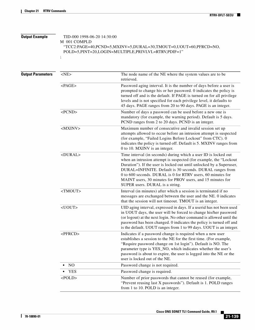
Chapter 21 RTRV CommandsRTRV-DFLT-SECU
Output Example TID-000 1998-06-20 14:30:00M 001 COMPLD “TCC2:PAGE=40,PCND=5,MXINV=5,DURAL=30,TMOUT=0,UOUT=60,PFRCD=NO, POLD=5,PINT=20,LOGIN=MULTIPLE,PRIVLVL=RTRV,PDIF=1”;
Output Parameters <NE> The node name of the NE where the system values are to be retrieved.
<PAGE> Password aging interval. It is the number of days before a user is prompted to change his or her password. 0 indicates the policy is turned off and is the default. If PAGE is turned on for all privilege levels and is not specified for each privilege level, it defaults to 45 days. PAGE ranges from 20 to 90 days. PAGE is an integer.
<PCND> Number of days a password can be used before a new one is mandatory (for example, the warning period). Default is 5 days. PCND ranges from 2 to 20 days. PCND is an integer.
<MXINV> Maximum number of consecutive and invalid session set up attempts allowed to occur before an intrusion attempt is suspected (for example, “Failed Logins Before Lockout” from CTC). 0 indicates the policy is turned off. Default is 5. MXINV ranges from 0 to 10. MXINV is an integer.
<DURAL> Time interval (in seconds) during which a user ID is locked out when an intrusion attempt is suspected (for example, the “Lockout Duration”). If the user is locked out until unlocked by a Superuser, DURAL=INFINITE. Default is 30 seconds. DURAL ranges from 0 to 600 seconds. DURAL is 0 for RTRV users, 60 minutes for MAINT users, 30 minutes for PROV users, and 15 minutes for SUPER users. DURAL is a string.
<TMOUT> Interval (in minutes) after which a session is terminated if no messages are exchanged between the user and the NE. 0 indicates that the session will not timeout. TMOUT is an integer.
<UOUT> UID aging interval, expressed in days. If a userid has not been used in UOUT days, the user will be forced to change his/her password (or logout) at the next login. No other command is allowed until the password has been changed. 0 indicates the policy is turned off and is the default. UOUT ranges from 1 to 99 days. UOUT is an integer.
<PFRCD> Indicates if a password change is required when a new user establishes a session to the NE for the first time. (For example, “Require password change on 1st login”). Default is NO. The parameter type is YES_NO, which indicates whether the user’s password is about to expire, the user is logged into the NE or the user is locked out of the NE.
• NO Password change is not required.
• YES Password change is required.
<POLD> Number of prior passwords that cannot be reused (for example, “Prevent reusing last X passwords”). Default is 1. POLD ranges from 1 to 10. POLD is an integer.
21-139Cisco ONS SONET TL1 Command Guide, R9.1
78-18890-01

Chapter 21 RTRV CommandsRTRV-DS1
21.39 RTRV-DS1(Cisco ONS 15454) The Retrieve DS1 (RTRV-DS1) command retrieves the test access attributes on a DS1 layer of a DS3XM card.
Note Frame format is not applicable to even port less ports on DS3XM-12 card and cannot be retrieved through RTRV-DS1 command.
Usage Guidelines • Both the MODE and the FMT fields of this command are applied for the DS3XM-12 card only.
• If the DS1 mode of the DS3XM-12 is ATT, the DS1 path can retrieve AT&T/54016 FEND PM counts up to 96 15-minute intervals; if the DS1 mode of the DS3XM-12 is FDL, the DS1 path can retrieve FDL/T1-403 FEND PM counts up to 32 15-minute intervals in RTRV-PM-DS1.
• For the DS3XM-12 card, the DS1 frame format NE default is AUTO_PROV_FMT for the first 30 seconds to determine the real format. After 30 seconds, the DS1 frame format is the detected frame. If the frame format is not determined, it will be in the UNFRAMED format.
• For the preprovisioning DS3XM-12 card, its DS1 frame format defaults to UNFRAMED.
• For the DS3XM-12 card, the DS1-configurable attributes (PM, TH, alarm, etc.) only apply to the ported ports (1 to 12) and the VT-mapped (odd) portless ports in xxx-xxx-DS1 commands. Provisioning or retrieving DS1 attributes on the DS3-mapped (even) portless ports in xxx-xxx-DS1 commands is not allowed.
• The parameters BERTMODE, BERTPATTERN, BERTERRCOUNT, BERTERRRATE, and BERTSYNCSTATUS apply only to DS1/E1-56 and DS3XM-12 cards
<PINT> Number of days that must pass before a password can be changed. If PINT is 0, the policy is turned off. Default is off. PINT ranges from 20 to 95 days. PINT is an integer.
<LOGIN> Number of times a user can log into an NE. LOGIN is either SINGLE or MULTIPLE. If LOGIN is SINGLE, a user can only log into an NE one time with any given userid, regardless of the method of login (for example, CTC, TL1, etc.). Default is MULTIPLE. The parameter type is USER_LOGINS, which is the number of times a user can log into the same NE with the same user ID.
• MULTIPLE A user can log into the same NE many times.
• SINGLE A user can log into the NE only once (includes both CTC and TL1 sessions).
<PRIVLVL> Parameter type is PRIVILEGE, which is the security level.
• MAINT Maintenance security level. Unlimited idle time.
• PROV Provision security level. 60 minutes of idle time.
• RTRV Retrieve security level. 30 minutes of idle time.
• SUPER Superuser security level. 15 minutes of idle time.
<PDIF> (Optional) Indicates how many characters must differ between old and new passwords. Default minimum character difference is 1. Ranges from 1 to 5 characters. PDIF is an integer.
21-140Cisco ONS SONET TL1 Command Guide, R9.1
78-18890-01
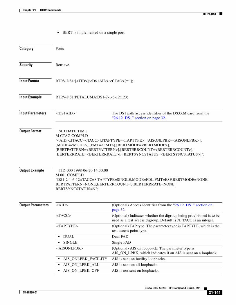
Chapter 21 RTRV CommandsRTRV-DS1
• BERT is implemented on a single port.
Category Ports
Security Retrieve
Input Format RTRV-DS1:[<TID>]:<DS1AID>:<CTAG>[::::];
Input Example RTRV-DS1:PETALUMA:DS1-2-1-6-12:123;
Input Parameters
Output Format SID DATE TIMEM CTAG COMPLD"<AID>::[TACC=<TACC>],[TAPTYPE=<TAPTYPE>],[AISONLPBK=<AISONLPBK>],[MODE=<MODE>],[FMT=<FMT>],[BERTMODE=<BERTMODE>],[BERTPATTERN=<BERTPATTERN>],[BERTERRCOUNT=<BERTERRCOUNT>],[BERTERRRATE=<BERTERRRATE>], [BERTSYNCSTATUS=<BERTSYNCSTATUS>]";
Output Example TID-000 1998-06-20 14:30:00M 001 COMPLD"DS1-2-1-6-12::TACC=8,TAPTYPE=SINGLE,MODE=FDL,FMT=ESF,BERTMODE=NONE,BERTPATTERN=NONE,BERTERRCOUNT=0,BERTERRRATE=NONE,BERTSYNCSTATUS=N";
Output Parameters
<DS1AID> The DS1 path access identifier of the DS3XM card from the “26.12 DS1” section on page 32.
<AID> (Optional) Access identifier from the “26.12 DS1” section on page 32.
<TACC> (Optional) Indicates whether the digroup being provisioned is to be used as a test access digroup. Default is N. TACC is an integer.
<TAPTYPE> (Optional) TAP type. The parameter type is TAPTYPE, which is the test access point type.
• DUAL Dual FAD
• SINGLE Single FAD
<AISONLPBK> (Optional) AIS on loopback. The parameter type is AIS_ON_LPBK, which indicates if an AIS is sent on a loopback.
• AIS_ONLPBK_FACILITY AIS is sent on facility loopbacks.
• AIS_ON_LPBK_ALL AIS is sent on all loopbacks.
• AIS_ON_LPBK_OFF AIS is not sent on loopbacks.
21-141Cisco ONS SONET TL1 Command Guide, R9.1
78-18890-01

Chapter 21 RTRV CommandsRTRV-DS1
• AIS_ON_LPBK_TERMINAL AIS is sent on terminal loopbacks.
<MODE> (Optional) Mode. The parameter type is DS1MODE, which is the DS1 path mode of the DS3XM-12 card
• ATT Indicates the DS1 path of the DS3XM-12 is in AT&T 54016 mode.
• FDL Indicates the DS1 path of the DS3XM-12 is in FDL T1-403 mode.
<FMT> (Optional) Digital signal frame format. The parameter type is FRAME_FORMAT, which is the frame format for a T1 port.
• D4 Frame format is D4.
• ESF Frame format is ESF.
• UNFRAMED Frame format is unframed.
<BERTMODE> Specifies the mode [Test Pattern Generator (TPG) or Test Pattern Monitor (TPM)] of the port for BERT.
• NONE BERT mode not enabled.
• TPGM-L Test pattern generator and monitor on line side.
• TPGM-B Test pattern generator and monitor on backplane.
• TPG-L Test pattern generator on line side.
• TPM-L Test pattern monitor on line side.
• TPG-B Test pattern generator on backplane.
• TPM-B Test pattern monitor on backplane.
<BERTPATTERN> Specifies the error pattern to be injected for BERT.
• NONE BERT pattern not enabled.
• PRBS15 PRBS15 test pattern.
• PRBS20 PRBS20 test pattern.
• PRBS23 PRBS23 test pattern.
• QRSS QRSS test pattern.
• ALT-ONE-ALT-ZERO Alternate one and zero pattern.
<BERTERRCOUNT> Integer value. Value -1 indicates that BERT is disabled/not supported.
<BERTERRRATE> Specifies the BERT error rate received.
• NONE No bit errors.
• SINGLE Single bit error.
• 1E-3 Bit errors in 1E-3 rate.
• 1E-4 Bit errors in 1E-4 rate.
• 1E-5 Bit errors in 1E-5 rate.
• 1E-6 Bit errors in 1E-6 rate.
<BERTSYNCSTATUS> Synchronization status of BERT values. The parameter type is Y_N, which specifies if synchronization status is up or down.
• Y BERT synchronization status is up.
• N BERT synchronization status is down.
21-142Cisco ONS SONET TL1 Command Guide, R9.1
78-18890-01

Chapter 21 RTRV CommandsRTRV-EC1
21.40 RTRV-EC1(Cisco ONS 15454, ONS 15310-MA) The Retrieve Electrical Carrier (RTRV-EC1) command retrieves the facility status of an EC1 card.
Usage Guidelines None
Category Ports
Security Retrieve
Input Format RTRV-EC1:[<TID>]:<AID>:<CTAG>[::::];
Input Example RTRV-EC1:CISCO:FAC-1-1:1234;
Input Parameters
Output Format SID DATE TIMEM CTAG COMPLD “<AID>::[PJMON=<PJMON>],[LBO=<LBO>],[RXEQUAL=<RXEQUAL>],[SOAK=<SOAK>], [SOAKLEFT=<SOAKLEFT>],[SFBER=<SFBER>],[SDBER=<SDBER>],[NAME=<NAME>], [EXPTRC=<EXPTRC>],[TRC=<TRC>],[TRCMODE=<TRCMODE>], [TRCFORMAT=<TRCFORMAT>],[AISONLPBK=<AISONLPBK>]:<PSTPSTQ>,[<SSTQ>]”;
Output Example TID-000 1998-06-20 14:30:00M 001 COMPLD “FAC-1-1::PJMON=0,LBO=0-225,RXEQUAL=Y,SOAK=52,SOAKLEFT=12-25,SFBER=1E-4, SDBER=1E-7,NAME=\"EC1 PORT\",EXPTRC="AAA",TRC="AAA",TRCMODE=MAN, TRCFORMAT=16-BYTE,AISONLPBK=AIS_ON_LPBK_ALL:IS-NR,AINS”;
Output Parameters
<AID> Access identifier from the “26.15 FACILITY” section on page 35.
<AID> Access identifier from the “26.15 FACILITY” section on page 35.
<PJMON> (Optional) A SONET pointer monitor attribute of an EC1 port. PJMON is an integer.
<LBO> (Optional) Line buildout settings. LBO is an integer. The parameter type is E_LBO, which is the electrical signal line buildout.
21-143Cisco ONS SONET TL1 Command Guide, R9.1
78-18890-01
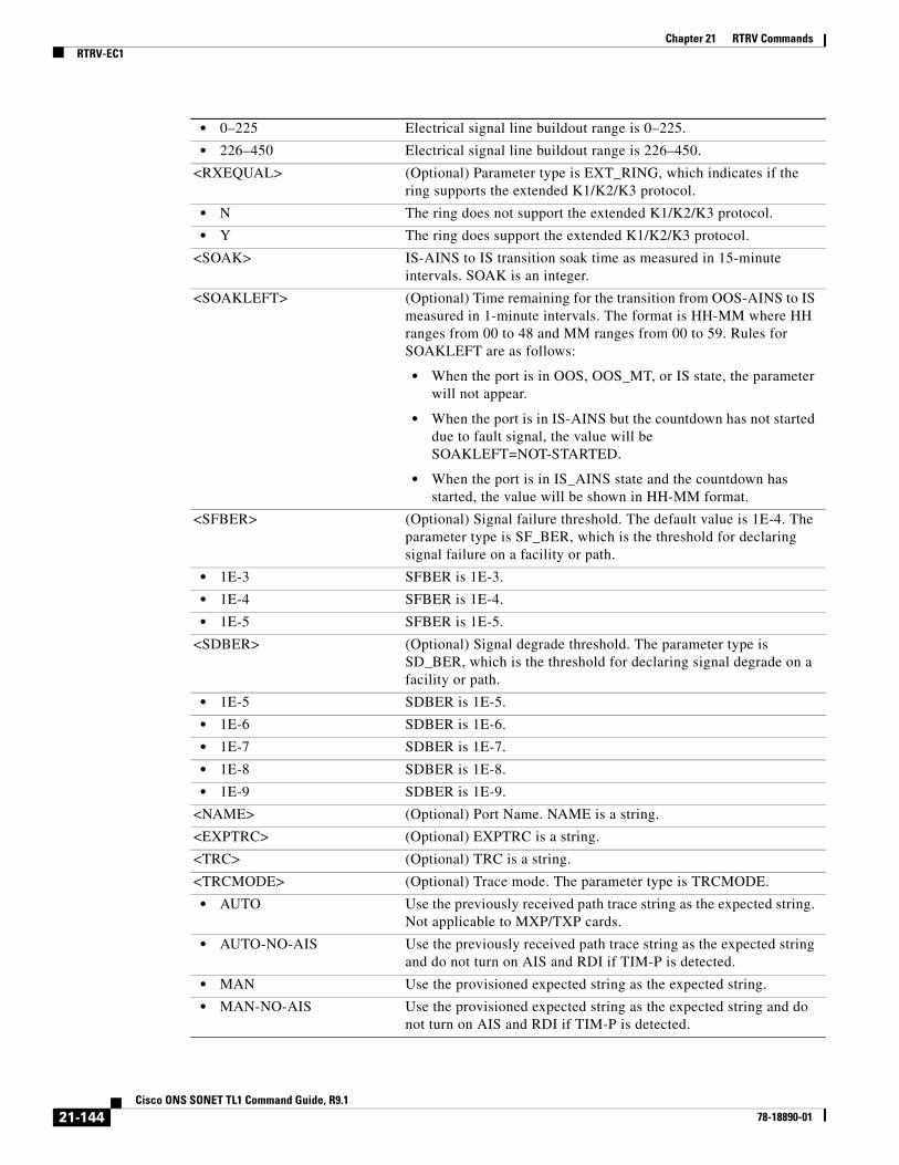
Chapter 21 RTRV CommandsRTRV-EC1
• 0–225 Electrical signal line buildout range is 0–225.
• 226–450 Electrical signal line buildout range is 226–450.
<RXEQUAL> (Optional) Parameter type is EXT_RING, which indicates if the ring supports the extended K1/K2/K3 protocol.
• N The ring does not support the extended K1/K2/K3 protocol.
• Y The ring does support the extended K1/K2/K3 protocol.
<SOAK> IS-AINS to IS transition soak time as measured in 15-minute intervals. SOAK is an integer.
<SOAKLEFT> (Optional) Time remaining for the transition from OOS-AINS to IS measured in 1-minute intervals. The format is HH-MM where HH ranges from 00 to 48 and MM ranges from 00 to 59. Rules for SOAKLEFT are as follows:
• When the port is in OOS, OOS_MT, or IS state, the parameter will not appear.
• When the port is in IS-AINS but the countdown has not started due to fault signal, the value will be SOAKLEFT=NOT-STARTED.
• When the port is in IS_AINS state and the countdown has started, the value will be shown in HH-MM format.
<SFBER> (Optional) Signal failure threshold. The default value is 1E-4. The parameter type is SF_BER, which is the threshold for declaring signal failure on a facility or path.
• 1E-3 SFBER is 1E-3.
• 1E-4 SFBER is 1E-4.
• 1E-5 SFBER is 1E-5.
<SDBER> (Optional) Signal degrade threshold. The parameter type is SD_BER, which is the threshold for declaring signal degrade on a facility or path.
• 1E-5 SDBER is 1E-5.
• 1E-6 SDBER is 1E-6.
• 1E-7 SDBER is 1E-7.
• 1E-8 SDBER is 1E-8.
• 1E-9 SDBER is 1E-9.
<NAME> (Optional) Port Name. NAME is a string.
<EXPTRC> (Optional) EXPTRC is a string.
<TRC> (Optional) TRC is a string.
<TRCMODE> (Optional) Trace mode. The parameter type is TRCMODE.
• AUTO Use the previously received path trace string as the expected string. Not applicable to MXP/TXP cards.
• AUTO-NO-AIS Use the previously received path trace string as the expected string and do not turn on AIS and RDI if TIM-P is detected.
• MAN Use the provisioned expected string as the expected string.
• MAN-NO-AIS Use the provisioned expected string as the expected string and do not turn on AIS and RDI if TIM-P is detected.
21-144Cisco ONS SONET TL1 Command Guide, R9.1
78-18890-01

Chapter 21 RTRV CommandsRTRV-EQPT
21.41 RTRV-EQPT(Cisco ONS 15454, 15327, 15600, 15310) The Retrieve Equipment (RTRV-EQPT) command retrieves the data parameters and state parameters associated with a card or shelf.
Usage Guidelines This command returns the PRTYPE, PROTID, RVTM, and RVRTV parameters for a card inside a protection group according to the following scenarios:
• A working AID/card within a 1:1 protection group will return PRTYPE, PROTID, RVTM, and RVRTV.
• A protection/AID card within a 1:1 protection group will return PRTYPE, RVTM, and RVRTV.
• OFF Turn off path trace capability. Nothing will be reported.
<TRCFORMAT> (Optional) Trace message size. The parameter type is TRCFORMAT (trace format).
• 1-BYTE 1-byte trace message
• 16-BYTE 16-byte trace message
• 64-BYTE 64-byte trace message
• Y Enable an attribute.
<AISONLPBK> (Optional) AIS on loopback. The parameter type is AIS_ON_LPBK, which indicates if an AIS is sent on a loopback.
• AIS_ONLPBK_FACILITY AIS is sent on facility loopbacks.
• AIS_ON_LPBK_ALL AIS is sent on all loopbacks.
• AIS_ON_LPBK_OFF AIS is not sent on loopbacks.
• AIS_ON_LPBK_TERMINAL AIS is sent on terminal loopbacks.
<PST_PSTQ> Administrative state in the PST_PSTQ format. The parameter type is PST_PSTQ, which is the service state of the entity described by the SST and PSTQ.
• IS-NR In Service and Normal
• OOS-AU Out of Service and Autonomous
• OOS-AUMA Out of Service and Autonomous Management
• OOS-MA Out of Service and Management
<SSTQ> (Optional) Secondary state of the entity. The parameter type is SST, which provides additional information pertaining to PST and PSTQ.
• AINS Automatic In-Service
• DSBLD Disabled
• LPBK Loopback
• MEA Mismatch of Equipment
• MT Maintenance
• OOG Out of Group
• SWDL Software Download
• UAS Unassigned
• UEQ Unequipped
21-145Cisco ONS SONET TL1 Command Guide, R9.1
78-18890-01

Chapter 21 RTRV CommandsRTRV-EQPT
• A working AID/card within a 1:N protection group will return PRTYPE, PROTID, RVTM, and RVRTV=Y.
• A protection AID/card of a 1:1 protection group will return PRTYPE, RVTM, and RVRTV=Y.
• An unprotected AID/card will return the AID type, equip (equip/unequip), status (act/standby), and state (IS/OOS) values.
• Preprovisioned cards (without being plugged in) will display OOS,AINS for PST and SST. After the card is plugged in and has gone through its initialization sequence, the card automatically goes to IS state (PST).
• The CARDMODE parameter is displayed for ML-Series Ethernet, FC_MR-4, DS1/E1-56, and DWDM xponder cards.
• The RETIME parameter is only displayed for the DS1/E1-56 (ONS 15454) and DS1-84-DS3-EC1-3 (ONS 15310-MA SONET) cards.
• The TRANSMODE parameter is only displayed for the DS1/E1-56 card.
Error conditions:
• The NE will generate an error when the equipment is not provisioned.
Category Equipment
Security Retrieve
Input Format RTRV-EQPT:[<TID>]:<AID>:<CTAG>[::::];
Input Example RTRV-EQPT:MIRABEL:SLOT-12:230;
Input Parameters
Output Format SID DATE TIMEM CTAG COMPLD“<AID>:<AIDTYPE>,<EQUIP>,[<ROLE>],[<STATUS>]:[<PROTID>],[<PRTYPE>],[<RVRTV>],[<RVTM>],[<CARDNAME>],[<IOSCFG>],[<CARDMODE>],[<PEERID>],[<REGENNAME>],[<PEERNAME>],[<TRANSMODE>],[<RETIME>],[<SHELFROLE>],[<FRPROLE>],[<FRPSTATE>],[<FRPHOLDOFFTIME>]:<PST>,[<SST>]”;
Output Example TID-000 1998-06-20 14:30:00M 001 COMPLD “SLOT-12:E1-42,EQUIP,,ACT:PROTID=SLOT-13,PRTYPE=1-1,RVRTV=Y,RVTM=8.5, CARDNAME=DESCRIPTION,IOSCFG=“IOS CONFIG INFO FOR ML SERIES CARD”, CARDMODE=DWDM-LINE,PEERID=SLOT-1,REGENNAME=“THIS GROUP”,
<AID> Access identifier from the “26.14 EQPT” section on page 33.
21-146Cisco ONS SONET TL1 Command Guide, R9.1
78-18890-01
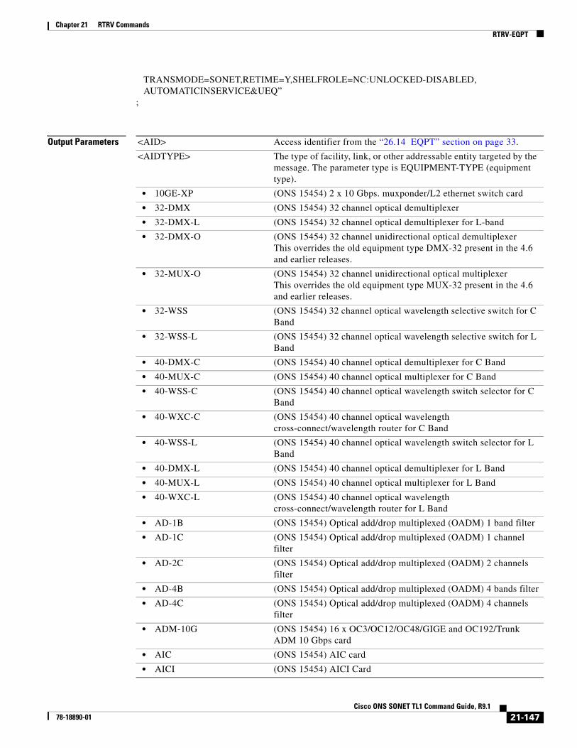
Chapter 21 RTRV CommandsRTRV-EQPT
TRANSMODE=SONET,RETIME=Y,SHELFROLE=NC:UNLOCKED-DISABLED, AUTOMATICINSERVICE&UEQ”;
Output Parameters <AID> Access identifier from the “26.14 EQPT” section on page 33.
<AIDTYPE> The type of facility, link, or other addressable entity targeted by the message. The parameter type is EQUIPMENT-TYPE (equipment type).
• 10GE-XP (ONS 15454) 2 x 10 Gbps. muxponder/L2 ethernet switch card
• 32-DMX (ONS 15454) 32 channel optical demultiplexer
• 32-DMX-L (ONS 15454) 32 channel optical demultiplexer for L-band
• 32-DMX-O (ONS 15454) 32 channel unidirectional optical demultiplexerThis overrides the old equipment type DMX-32 present in the 4.6 and earlier releases.
• 32-MUX-O (ONS 15454) 32 channel unidirectional optical multiplexerThis overrides the old equipment type MUX-32 present in the 4.6 and earlier releases.
• 32-WSS (ONS 15454) 32 channel optical wavelength selective switch for C Band
• 32-WSS-L (ONS 15454) 32 channel optical wavelength selective switch for L Band
• 40-DMX-C (ONS 15454) 40 channel optical demultiplexer for C Band
• 40-MUX-C (ONS 15454) 40 channel optical multiplexer for C Band
• 40-WSS-C (ONS 15454) 40 channel optical wavelength switch selector for C Band
• 40-WXC-C (ONS 15454) 40 channel optical wavelength cross-connect/wavelength router for C Band
• 40-WSS-L (ONS 15454) 40 channel optical wavelength switch selector for L Band
• 40-DMX-L (ONS 15454) 40 channel optical demultiplexer for L Band
• 40-MUX-L (ONS 15454) 40 channel optical multiplexer for L Band
• 40-WXC-L (ONS 15454) 40 channel optical wavelength cross-connect/wavelength router for L Band
• AD-1B (ONS 15454) Optical add/drop multiplexed (OADM) 1 band filter
• AD-1C (ONS 15454) Optical add/drop multiplexed (OADM) 1 channel filter
• AD-2C (ONS 15454) Optical add/drop multiplexed (OADM) 2 channels filter
• AD-4B (ONS 15454) Optical add/drop multiplexed (OADM) 4 bands filter
• AD-4C (ONS 15454) Optical add/drop multiplexed (OADM) 4 channels filter
• ADM-10G (ONS 15454) 16 x OC3/OC12/OC48/GIGE and OC192/Trunk ADM 10 Gbps card
• AIC (ONS 15454) AIC card
• AICI (ONS 15454) AICI Card
21-147Cisco ONS SONET TL1 Command Guide, R9.1
78-18890-01

Chapter 21 RTRV CommandsRTRV-EQPT
• ASAP-4 (ONS 15600) Any service any port (ASAP) carrier card with four PIM slots
• CE-1000-4 (ONS 15454) Modena mapper card
• CE-100T-8 (ONS 15310-MA SONET) Exige/Elise mapper card
• CE-MR-6 (ONS 15310-MA SONET) CE-MR-6 data card
• CE-MR-10 (ONS 15454) CE-MR-10 data card
• CTX2500 (ONS 15310-MA SONET) CTX2500 card
• CXC (ONS 15600) Cross connect card
• DS1 (ONS 15454) DS1 card
• DS1-E1-56 (ONS 15454) DS1-E1-56 card
• DS1-28-DS3-EC1-3 (ONS 15310-MA SONET) DS1-28-DS3-EC1-3 card
• DS1-84-DS3-EC1-3 (ONS 15310-MA SONET) DS1-84-DS3-EC1-3 card
• DS1I (ONS 15454) DS1I card
• DS1N (ONS 15454) DS1N card
• DS3 (ONS 15454) DS3 card
• DS3-EC1-48 (ONS 15454) DS3-EC1-48 card
• DS3E (ONS 15454) DS3E card
• DS3I (ONS 15454) DS31 card
• DS3IN (ONS 15454) DS3IN card
• DS3N (ONS 15454) DS3N card
• DS3NE (ONS 15454) DS3NE card
• DS3XM (ONS 15454) DS3XM card
• DS3XM-12 (ONS 15454) DS3XM-12 card
• E1000T (ONS 15454) E1000T card
• E100T (ONS 15454) E100T card
• EC1 (ONS 15454) EC1 card
• FC-MR-4 (ONS 15454) FC-MR-4 card
• FILLER-CARD (ONS 15454, ONS 15600) Blank filler card
• G1000-2 (ONS 15454) A 2-port G1000 card
• G1000-4 (ONS 15454) A 4-port G1000 card
• GE-XP (ONS 15454) 20 x 1 Gbps muxponder/L2 ethernet switch card
• MD-4 (ONS 15454) Four channel optical multiplexer/demultiplexer
• ML-100T-8 (ONS 15310-MA SONET) Exige/Elise mapper card
• ML1000-2 (ONS 15454) Daytona 2-port GigE
• ML100T-12 (ONS 15454) Daytona 12-port FSTE
• ML100X-8 (ONS 15454) 8-port 100T card with optical interface
• ML-MR-10 (ONS 15454) ML-MR-10 card
• MMU Multi-Ring / Mesh Upgrade unit
• MRC-12 (ONS 15454) Humvee - 12-port multirate optical card
• MS-ISC-100T (ONS 15454) Fast Ethernet switch card used for internal shelves connection
• MRC-2.5G-4 (ONS 15454) 4-port MRC 2.5G (Hummer 4 15454-ANSI card)
21-148Cisco ONS SONET TL1 Command Guide, R9.1
78-18890-01
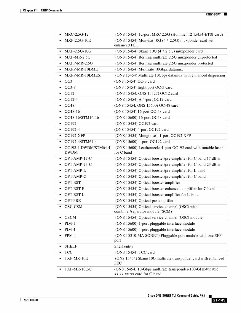
Chapter 21 RTRV CommandsRTRV-EQPT
• MRC-2.5G-12 (ONS 15454) 12-port MRC 2.5G (Hummer 12 15454-ETSI card)
• MXP-2.5G-10E (ONS 15454) Monviso 10G (4 * 2.5G) muxponder card with enhanced FEC
• MXP-2.5G-10G (ONS 15454) Skane 10G (4 * 2.5G) muxponder card
• MXP-MR-2.5G (ONS 15454) Bernina multirate 2.5G muxponder unprotected
• MXPP-MR-2.5G (ONS 15454) Bernina multirate 2.5G muxponder protected
• MXPP-MR-10DME (ONS 15454) Multirate 10Gbps datamux
• MXPP-MR-10DMEX (ONS 15454) Multirate 10Gbps datamux with enhanced dispersion
• OC3 (ONS 15454) OC-3 card
• OC3-8 (ONS 15454) Eight port OC-3 card
• OC12 (ONS 15454, ONS 15327) OC12 card
• OC12-4 (ONS 15454) A 4-port OC12 card
• OC48 (ONS 15454, ONS 15600) OC-48 card
• OC48-16 (ONS 15454) 16 port OC-48 card
• OC48-16/STM16-16 (ONS 15600) 16-port OC48 card
• OC192 (ONS 15454) OC192 card
• OC192-4 (ONS 15454) 4-port OC192 card
• OC192-XFP (ONS 15454) Mongoose - 1-port OC192 XFP
• OC192-4/STM64-4 (ONS 15600) 4-port OC192 card
• OC192-4-DWDM/STM64-4-DWDM
(ONS 15600) Leatherneck: 4-port OC192 card with tunable laser for C band
• OPT-AMP-17-C (ONS 15454) Optical booster/pre-amplifier for C band 17 dBm
• OPT-AMP-23-C (ONS 15454) Optical booster/pre-amplifier for C band 23 dBm
• OPT-AMP-L (ONS 15454) Optical booster/pre-amplifier for L band
• OPT-AMP-C (ONS 15454) Optical booster/pre-amplifier for C band
• OPT-BST (ONS 15454) Optical booster amplifier
• OPT-BST-E (ONS 15454) Optical booster enhanced amplifier for C band
• OPT-BST-L (ONS 15454) Optical booster amplifier for L band
• OPT-PRE (ONS 15454) Optical pre-amplifier
• OSC-CSM (ONS 15454) Optical service channel (OSC) with combiner/separator module (SCM)
• OSCM (ONS 15454) Optical service channel (OSC) module
• PIM-1 (ONS 15600) 1-port pluggable interface module
• PIM-4 (ONS 15600) 4-port pluggable interface module
• PPM-1 (ONS 15310-MA SONET) Pluggable port module with one SFP port
• SHELF Shelf entity
• TCC (ONS 15454) TCC card
• TXP-MR-10E (ONS 15454) Skane 10G multirate transponder card with enhanced FEC
• TXP-MR-10E-C (ONS 15454) 10-Gbps multirate transponder-100-GHz-tunable xx.xx-xx.xx card for C-band
21-149Cisco ONS SONET TL1 Command Guide, R9.1
78-18890-01
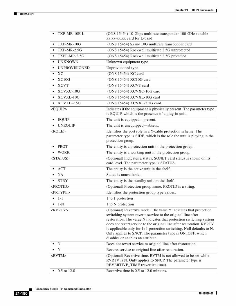
Chapter 21 RTRV CommandsRTRV-EQPT
• TXP-MR-10E-L (ONS 15454) 10-Gbps multirate transponder-100-GHz-tunable xx.xx-xx.xx card for L-band
• TXP-MR-10G (ONS 15454) Skane 10G multirate transponder card
• TXP-MR-2.5G (ONS 15454) Rockwell multirate 2.5G unprotected
• TXPP-MR-2.5G (ONS 15454) Rockwell multirate 2.5G protected
• UNKNOWN Unknown equipment type
• UNPROVISIONED Unprovisioned type
• XC (ONS 15454) XC card
• XC10G (ONS 15454) XC10G card
• XCVT (ONS 15454) XCVT card
• XCVXC-10G (ONS 15454) XCVXC-10G card
• XCVXL-10G (ONS 15454) XCVXL-10G card
• XCVXL-2.5G (ONS 15454) XCVXL-2.5G card
<EQUIP> Indicates if the equipment is physically present. The parameter type is EQUIP, which is the presence of a plug-in unit.
• EQUIP The unit is equipped—present.
• UNEQUIP The unit is unequipped—absent.
<ROLE> Identifies the port role in a Y-cable protection scheme. The parameter type is SIDE, which is the role the unit is playing in the protection group.
• PROT The entity is a protection unit in the protection group.
• WORK The entity is a working unit in the protection group.
<STATUS> (Optional) Indicates a status. SONET card status is shown on its card level. The parameter type is STATUS.
• ACT The entity is the active unit in the shelf.
• NA Status is unavailable.
• STBY The entity is the standby unit on the shelf.
<PROTID> (Optional) Protection group name. PROTID is a string.
<PRTYPE> Identifies the protection group type values.
• 1-1 1 to 1 protection
• 1-N 1 to N protection
<RVRTV> (Optional) Revertive mode. The value Y indicates that protection switching system reverts service to the original line after restoration. The value N indicates that protection switching system does not revert service to the original line after restoration. RVRTV is applicable only for 1+1 protection switching. Null defaults to N. Only applies to SNCP. The parameter type is ON_OFF, which disables or enables an attribute.
• N Does not revert service to original line after restoration.
• Y Reverts service to original line after restoration.
<RVTM> (Optional) Revertive time. RVTM is not allowed to be set while RVRTV is N. Only applies to SNCP. The parameter type is REVERTIVE_TIME (revertive time).
• 0.5 to 12.0 Revertive time is 0.5 to 12.0 minutes.
21-150Cisco ONS SONET TL1 Command Guide, R9.1
78-18890-01

Chapter 21 RTRV CommandsRTRV-EQPT
<CARDNAME> (Optional) The card name of the card, PIM, or PPM equipment. CARDNAME is a string.
<IOSCFG> (Optional) Displays the information about startup IOS config file for the ML series card. A example of this field is "TL1,11.22.33.44//DIR/IOS.CONF,2002/1/1 9:1:1 EST". The following information is included in this field: 1) Where the config file is from: TL1, or CTC/CTM/CLI/TCC; 2) The host (IP address)/directory/file name, if the config file is downloaded from the network; 3) When the startup config file is created (by copying from the network, for example). This field only applies to ML series card. IOSCFG is a string.
<CARDMODE> (Optional) Card mode. The parameter type is CARDMODE, which is the card mode. Card mode is applicable to cards that have multiple capabilities, for example, the ML-Series card can operate in two distinct modes: Linear Mapper Mode and L2/L3 Mode.
• 10GEXP-TXP 10GE-XP behaves as 2 separate Transponders, where client 1 is associated to trunk 3 and client 2 is associated to trunk 4
• 10GEXP-L2ETH 10GE-XP behaves as a L2 Ethernet Switch
• 10GLANWAN-LINE-SQUELCH
Changes the card mode from LAN to WAN.
• AMPL-BST The optical amplifier is working as an optical booster
• AMPL-PRE The optical amplifier is working as an optical preamplifier
• CEMR-AUTO Auto allocation of back-end channels for CE-MR-10 (Cisco ONS 15454 only) and CE-MR-6 (Cisco ONS 15310-MA SONET only) cards.
• CEMR-MANUAL Manual allocation of back-end channels for CE-MR-10 (Cisco ONS 15454 only) and CE-MR-6 (Cisco ONS 15310-MA SONET only) cards.
• DS1E1-DS1ONLY DS1 mode on DS1E1 card
• DS1E1-E1ONLY E1 mode on DS1E1 card
• DS3XM12-STS12 The DS3XM-12 card in the STS12 backplane rate mode
• DS3XM12-STS48 The DS3XM-12 card in the STS48 backplane rate mode
• DWDM-LINE Line terminating mode
• DWDM-SECTION Section terminating mode
• DWDM-TRANS-AIS Transparent mode AIS
• DWDM-TRANS-SQUELCH Transparent mode SQUELCH
• FCMR-DISTEXTN FC_MR-4 card with distance extension support
• FCMR-LINERATE FC_MR-4 card without distance extension support
• GEXP-10x1Gx2-MXP GE-XP behaves as a double Muxponder having ten 1 Gbps client facilities with one trunk. The first 10 GIGE clients are associated to the first trunk (21), while GIGE facilities from 11 to 20 are associated to trunk 22.
• GEXP-20x1G-MXP GE-XP behaves as a single Muxponder having ten 1 Gbps client facilities with one trunk. Only the first 10 GIGE clients are associated to the first trunk (21) while the other facilities are unused.
• GEXP-L2ETH GE-XP behaves as an L2 Ethernet Switch.
21-151Cisco ONS SONET TL1 Command Guide, R9.1
78-18890-01

Chapter 21 RTRV CommandsRTRV-EQPT
• MXPMR10DME-4GFC 4-Gbps Fibre Channel/FICON mode for the Cisco ONS 15454 MXP_MR_10DME_C and MXP_MR_10DME_L cards supported on Ports 1 and 5
• MXPMR10DME-4GFC-FCGEISC
4-Gbps Fibre Channel/FICON supported on Port 1 and Fibre Channel, GIGE, and ISC modes for the Cisco ONS 15454 MXP_MR_10DME_C and MXP_MR_10DME_L cards supported on Ports 5 to 8
• MXPMR10DME-FCGEISC Fibre Channel, GIGE, and ISC modes for the Cisco ONS 15454 MXP_MR_10DME_C and MXP_MR_10DME_L cards supported on all eight ports
• MXPMR10DME-FCGEISC-4GFC
Fibre Channel, GIGE, and ISC modes for the Cisco ONS 15454 MXP_MR_10DME_C and MXP_MR_10DME_L cards supported on Ports 1 to 4 and 4-Gbps Fibre Channel/FICON supported on Port 5
• MXPMR10G-FCGEISC Fibre Channel, GIGE, and ISC modes for the Cisco ONS 15454 MXP_MR_10DME_C and MXP_MR_10DME_L cards supported on all eight ports
• MXPMR10G-4GFC 4-Gbps Fibre Channel/FICON mode for the Cisco ONS 15454 MXP_MR_10DME_C and MXP_MR_10DME_L cards supported on Ports 1 and 5
• MXPMR10G-FCGEISC-4GFC
Fibre Channel, GIGE, and ISC modes for the Cisco ONS 15454 MXP_MR_10DME_C and MXP_MR_10DME_L cards supported on Ports 1 to 4 and 4-Gbps Fibre Channel/FICON supported on Port 5
• MXPMR10G-4GFC-FCGEISC
4-Gbps Fibre Channel/FICON supported on Port 1 and Fibre Channel, GIGE, and ISC modes for the Cisco ONS 15454 MXP_MR_10DME_C and MXP_MR_10DME_L cards supported on Ports 5 to 8.
• MXPMR25G-ESCON ESCON mode for the Cisco ONS 15454 MXP_2.5G_10G card
• MXPMR25G-FCGE Fibre channel or GIGE mode for the MXP_2.5G_10G card
• MXPMR25G-MIXED Mixed Fibre Channel, GIGE, and ESCON modes for the Cisco ONS 15454 MXP_2.5G_10G card
• PSM-NORMAL PSM working in classic configuration.
• PSM-STANDALONE PSM working in stand-alone mode.
• UNKNOWN Unknown equipment type
• WXC80-BIDI 80-WXC-C working in bidirectional mode.
• WXC80-DMX 80-WXC-C working as demultiplexer.
• WXC80-MUX 80-WXC-C working as multiplexer.
<PEERID> Indicates the peer trunk facility of the regeneration group on the OTU2-XP card. Accessed using the CHAN AID.
<REGENNAME> Indicates the name of a regeneration group. Applicable only to DWDM flavored cards, which support regeneration group. Regenname is a string. The default value is "NULL".
<PEERNAME> PEERNAME is a user-specified string used to identify ADM-10G peer groups. It defaults to NULL. Its maximum length is 32 characters.
<TRANSMODE> Transition Mode.
21-152Cisco ONS SONET TL1 Command Guide, R9.1
78-18890-01

Chapter 21 RTRV CommandsRTRV-EQPT
• AU3 Au3 mode.
• AU4 Au4 mode.
• SONET Sonnet mode.
<RETIME> (Optional) Indicates the RETIME function for all the facilities on this card. Applies only to the DS1/E1-56 card. The parameter type is ON_OFF (disable or enable an attribute). (Supported on the E1-21-DS3-E3-3 and E1-63-DS3-E3-3 card for Cisco ONS 15310 MA platform).
• N Disable an attribute.
• Y Enable an attribute.
<SHELFROLE> The role of the shelf in the context of the node. When it is omitted it defaults to SC. The parameter is SHELF_ROLE.
<FRPROLE> Indicates the fast ring protection enable mode for GE-XP/10GE-XP units involved in a protection scheme.
• MASTER Role is of card master of the ring.
• SLAVE Role is of card slave of the ring.
<FRPSTATE> Indicates the fast ring protection enable state.
• DISABLED Disabled protection
• ENABLED Enabled protection
• FORCED Forced protection
<FRPHOLDOFFTIME> Indicates the hold off timer value. The protection do not start until the hold off expire.
• 100-MSEC Indicates the hold off timer value as 100 milliseconds.
• 1-MSEC Indicates the hold off timer value as 1milisecond.
• 200-MSEC Indicates the hold off timer value as 200 milliseconds.
• 2-MSEC Indicates the hold off timer value as 2 milliseconds.
• 500-MSEC Indicates the hold off timer value as 500 milliseconds.
• 50-MSEC Indicates the hold off timer value as 50 milliseconds.
• 5-MSEC Indicates the hold off timer value as 50 milliseconds.
• DISABLED Indicates that the hold off timer is disabled.
<PST> (Optional) Primary state of the entity. The parameter type is PST, which indicates the current overall service condition of an entity.
• IS-NR In Service and Normal
• OOS-AU Out of Service and Autonomous
• OOS-AUMA Out of Service and Autonomous Management
• OOS-MA Out of Service and Management
<SST> Secondary state of the entity. Listable. The parameter type is SST, which provides additional information pertaining to PST and PSTQ.
• AINS Automatic In-Service
• DSBLD Disabled
• LPBK Loopback
• MEA Mismatch of Equipment
• MT Maintenance
21-153Cisco ONS SONET TL1 Command Guide, R9.1
78-18890-01

Chapter 21 RTRV CommandsRTRV-ESCON
21.42 RTRV-ESCON(Cisco ONS 15454) The Retrieve Enterprise System Connection (RTRV-ESCON) command retrieves the Fibre Channel-specific settings for ports that have been configured to carry ESCON traffic using the ENT-ESCON command.
Usage Guidelines None
Category Ports
Security Retrieve
Input Format RTRV-ESCON:[<TID>]:<AID>:<CTAG>;
Input Example RTRV-ESCON::CISCO:FAC-1-1:123;
Input Parameters
Output Format SID DATE TIMEM CTAG COMPLD “<AID>:,,[<ROLE>],[<STATUS>]:[ENCAP=<ENCAP>]”;
Output Example TID-000 1998-06-20 14:30:00M 001 COMPLD “FAC-1-1:,,WORK,ACT:ENCAP=GFP-T”;
Output Parameters
• OOG Out of Group
• SWDL Software Download
• UAS Unassigned
• UEQ Unequipped
<AID> Access identifier from the “26.15 FACILITY” section on page 35.
<AID> Access identifier from the “26.15 FACILITY” section on page 35.
<ROLE> (Optional) The port role in Y-cable protection (WORK or PROT). The parameter type is SIDE, which is the role the unit is playing in the protection group.
21-154Cisco ONS SONET TL1 Command Guide, R9.1
78-18890-01

Chapter 21 RTRV CommandsRTRV-ETH
21.43 RTRV-ETH(Cisco ONS 15454) The Retrieve Ethernet (RTRV-ETH) command retrieves the front-end port information of an Ethernet card.
Usage Guidelines This command retrieves the front-end port information of 10/100/1000 Mbps Ethernet cards. However, RTRV-POS will display the MTU, which is common for front and backend ports.
The SELECTIVEAUTO parameter is applicable only when EXPSPEED and EXPDUPLEX are not set to AUTO mode.
Note This command is available in Software Release 8.0.1 and later. It is not available in R8.0.0 and later.
Category Ethernet
Security Provisioning
Input Format RTRV-ETH:[<TID>]:<AID>:<CTAG>[:::];
Input Example RTRV-ETH:TID:FAC-1-1:CTAG;
• PROT The entity is a protection unit in the protection group.
• WORK The entity is a working unit in the protection group.
<STATUS> (Optional) A port status in Y-cable protection (ACT or STBY). The parameter type is STATUS, which is the status of the unit in the protection pair.
• ACT The entity is the active unit in the shelf.
• NA Status is unavailable.
• STBY The entity is the standby unit in the shelf.
<ENCAP> (Optional) Encapsulation frame type. The parameter type is ENCAP, which is the frame encapsulation type.
• GFP_F GFP Frame Mode
• GFP_T GFP Transparent Mode
• HDLC HDLC Frame Mode
• HDLC_LEX HDLC LAN Extension Frame Mode
• HDLC_X86 HDLC X.86 Frame Mode
21-155Cisco ONS SONET TL1 Command Guide, R9.1
78-18890-01
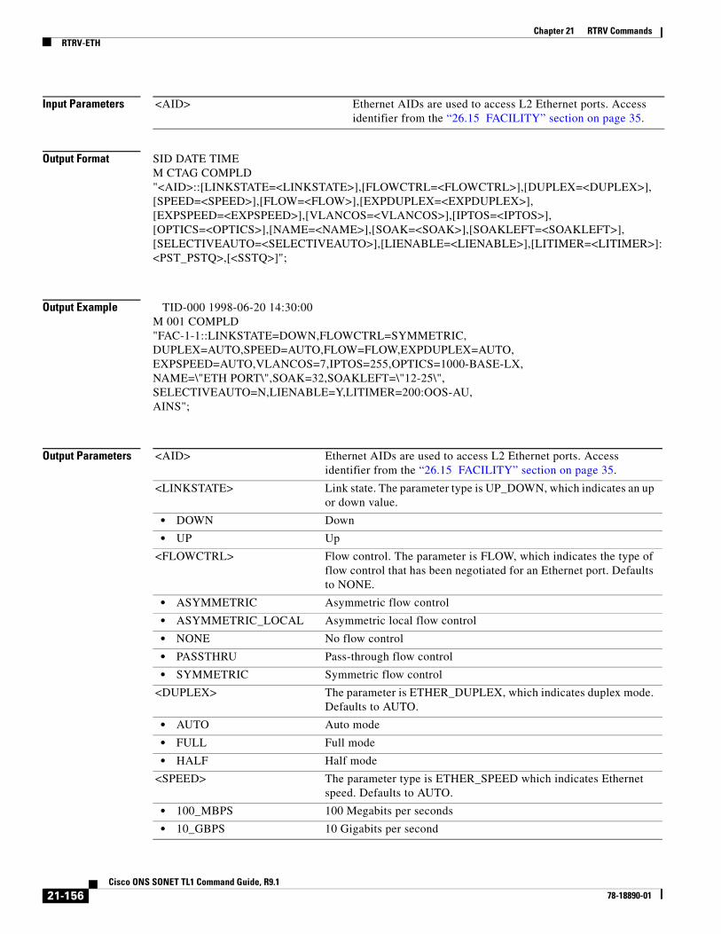
Chapter 21 RTRV CommandsRTRV-ETH
Input Parameters
Output Format SID DATE TIMEM CTAG COMPLD"<AID>::[LINKSTATE=<LINKSTATE>],[FLOWCTRL=<FLOWCTRL>],[DUPLEX=<DUPLEX>],[SPEED=<SPEED>],[FLOW=<FLOW>],[EXPDUPLEX=<EXPDUPLEX>],[EXPSPEED=<EXPSPEED>],[VLANCOS=<VLANCOS>],[IPTOS=<IPTOS>],[OPTICS=<OPTICS>],[NAME=<NAME>],[SOAK=<SOAK>],[SOAKLEFT=<SOAKLEFT>],[SELECTIVEAUTO=<SELECTIVEAUTO>],[LIENABLE=<LIENABLE>],[LITIMER=<LITIMER>]:<PST_PSTQ>,[<SSTQ>]";
Output Example TID-000 1998-06-20 14:30:00M 001 COMPLD"FAC-1-1::LINKSTATE=DOWN,FLOWCTRL=SYMMETRIC, DUPLEX=AUTO,SPEED=AUTO,FLOW=FLOW,EXPDUPLEX=AUTO,EXPSPEED=AUTO,VLANCOS=7,IPTOS=255,OPTICS=1000-BASE-LX,NAME=\"ETH PORT\",SOAK=32,SOAKLEFT=\"12-25\", SELECTIVEAUTO=N,LIENABLE=Y,LITIMER=200:OOS-AU,AINS";
Output Parameters
<AID> Ethernet AIDs are used to access L2 Ethernet ports. Access identifier from the “26.15 FACILITY” section on page 35.
<AID> Ethernet AIDs are used to access L2 Ethernet ports. Access identifier from the “26.15 FACILITY” section on page 35.
<LINKSTATE> Link state. The parameter type is UP_DOWN, which indicates an up or down value.
• DOWN Down
• UP Up
<FLOWCTRL> Flow control. The parameter is FLOW, which indicates the type of flow control that has been negotiated for an Ethernet port. Defaults to NONE.
• ASYMMETRIC Asymmetric flow control
• ASYMMETRIC_LOCAL Asymmetric local flow control
• NONE No flow control
• PASSTHRU Pass-through flow control
• SYMMETRIC Symmetric flow control
<DUPLEX> The parameter is ETHER_DUPLEX, which indicates duplex mode. Defaults to AUTO.
• AUTO Auto mode
• FULL Full mode
• HALF Half mode
<SPEED> The parameter type is ETHER_SPEED which indicates Ethernet speed. Defaults to AUTO.
• 100_MBPS 100 Megabits per seconds
• 10_GBPS 10 Gigabits per second
21-156Cisco ONS SONET TL1 Command Guide, R9.1
78-18890-01
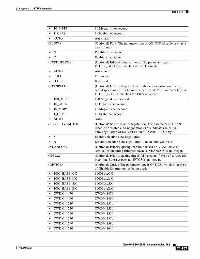
Chapter 21 RTRV CommandsRTRV-ETH
• 10_MBPS 10 Megabits per second
• 1_GBPS 1 Gigabit per second
• AUTO Automatic
<FLOW> (Optional) Flow. The parameter type is ON_OFF (disable or enable an attribute).
• N Disable an attribute.
• Y Enable an attribute.
<EXPDUPLEX> (Optional) Ethernet duplex mode. The parameter type is ETHER_DUPLEX, which is the duplex mode.
• AUTO Auto mode
• FULL Full mode
• HALF Half mode
<EXPSPEED> (Optional) Expected speed. Due to the auto-negotiation feature, actual speed may differ from expected speed. The parameter type is ETHER_SPEED, which is the Ethernet speed.
• 100_MBPS 100 Megabits per second
• 10_GBPS 10 Gigabits per second
• 10_MBPS 10 Megabits per second
• 1_GBPS 1 Gigabit per second
• AUTO Auto
<SELECTIVEAUTO> (Optional) Selective auto-negotiation. The parameter is Y or N (enable or disable auto-negotiation) This indicates selective auto-negotiation of EXPSPEED and EXPDUPLEX only.
• Y Enable selective auto-negotiation.
• N Disable selective auto-negotiation. The default value is N.
<VLANCOS> (Optional) Priority queing threshold based on VLAN class of service for incoming Ethernet packets. VLANCOS is an integer.
<IPTOS> (Optional) Priority queing threshold based on IP type of service for incoming Ethernet packets. IPTOS is an integer.
<OPTICS> (Optional) Optics. The parameter type is OPTICS, which is the type of Gigabit Ethernet optics being used.
• 1000_BASE_CX 1000BaseCX
• 1000_BASE_LX 1000BaseLX
• 1000_BASE_SX 1000BaseSX
• 1000_BASE_ZX 1000BaseZX
• CWDM_1470 CWDM 1470
• CWDM_1490 CWDM 1490
• CWDM_1510 CWDM 1510
• CWDM_1530 CWDM 1530
• CWDM_1550 CWDM 1550
• CWDM_1570 CWDM 1570
• CWDM_1590 CWDM 1590
• CWDM_1610 CWDM 1610
21-157Cisco ONS SONET TL1 Command Guide, R9.1
78-18890-01

Chapter 21 RTRV CommandsRTRV-ETH
• ITU_100G_1530_33 ITU-100G 1530.33
• ITU_100G_1531_12 ITU-100G 1531.12
• ITU_100G_1531_90 ITU-100G 1531.90
• ITU_100G_1532_68 ITU-100G 1532.68
• ITU_100G_1534_25 ITU-100G 1534.25
• ITU_100G_1535_04 ITU-100G 1535.04
• ITU_100G_1535_82 ITU-100G 1535.82
• ITU_100G_1536_61 ITU-100G 1536.61
• ITU_100G_1538_19 ITU-100G 1538.19
• ITU_100G_1538_98 ITU-100G 1538.98
• ITU_100G_1539_77 ITU-100G 1539.77
• ITU_100G_1540_56 ITU-100G 1540.56
• ITU_100G_1542_14 ITU-100G 1542.14
• ITU_100G_1542_94 ITU-100G 1542.94
• ITU_100G_1543_73 ITU-100G 1543.73
• ITU_100G_1544_53 ITU-100G 1544.53
• ITU_100G_1546_12 ITU-100G 1546.12
• ITU_100G_1546_92 ITU-100G 1546.92
• ITU_100G_1547_72 ITU-100G 1547.72
• ITU_100G_1548_51 ITU-100G 1548.51
• ITU_100G_1550_12 ITU-100G 1550.12
• ITU_100G_1550_92 ITU-100G 1550.92
• ITU_100G_1551_72 ITU-100G 1551.72
• ITU_100G_1552_52 ITU-100G 1552.52
• ITU_100G_1554_13 ITU-100G 1554.13
• ITU_100G_1554_94 ITU-100G 1554.94
• ITU_100G_1555_75 ITU-100G 1555.75
• ITU_100G_1556_55 ITU-100G 156.55
• ITU_100G_1558_17 ITU-100G 1558.17
• ITU_100G_1558_98 ITU-100G 1558.98
• ITU_100G_1559_79 ITU-100G 1559.79
• ITU_100G_1560_61 ITU-100G 1560.61
• UNKNOWN Unknown Optical Type
• UNPLUGGED Unplugged
<NAME> (Optional) Name. NAME is a string.
<SOAK> (Optional) OOS-AINS to IS transition soak time as measured in 15-minute intervals. SOAK is an integer.
21-158Cisco ONS SONET TL1 Command Guide, R9.1
78-18890-01
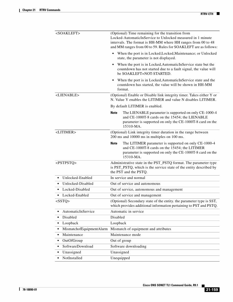
Chapter 21 RTRV CommandsRTRV-ETH
<SOAKLEFT> (Optional) Time remaining for the transition from Locked-AutomaticInService to Unlocked measured in 1 minute intervals. The format is HH-MM where HH ranges from 00 to 48 and MM ranges from 00 to 59. Rules for SOAKLEFT are as follows:
• When the port is in Locked;Locked,Maintenance; or Unlocked state, the parameter is not displayed.
• When the port is in Locked,AutomaticInService state but the countdown has not started due to a fault signal, the value will be SOAKLEFT=NOT-STARTED.
• When the port is in Locked,AutomaticInService state and the countdown has started, the value will be shown in HH-MM format.
<LIENABLE> (Optional) Enable or Disable link integrity timer. Takes either Y or N. Value Y enables the LITIMER and value N disables LITIMER.
By default LITIMER is enabled.
Note The LIENABLE parameter is supported on only CE-1000-4 and CE-1000T-8 cards on the 15454; the LIENABLE parameter is supported on only the CE-1000T-8 card on the 15310-MA.
<LITIMER> (Optional) Link integrity timer duration in the range between 200 ms and 10000 ms in multiples on 100 ms.
Note The LITIMER parameter is supported on only CE-1000-4 and CE-1000T-8 cards on the 15454; the LITIMER parameter is supported on only the CE-1000T-8 card on the 15310-MA.
<PSTPSTQ> Administrative state in the PST_PSTQ format. The parameter type is PST_PSTQ, which is the service state of the entity described by the PST and the PSTQ.
• Unlocked-Enabled In service and normal
• Unlocked-Disabled Out of service and autonomous
• Locked-Disabled Out of service, autonomous and management
• Locked-Enabled Out of service and management
<SSTQ> (Optional) Secondary state of the entity. the parameter type is SST, which provides additional information pertaining to PST and PSTQ.
• AutomaticInService Automatic in service
• Disabled Disabled
• Loopback Loopback
• MismatchofEquipmentAlarm Mismatch of equipment and attributes
• Maintenance Maintenance mode
• OutOfGroup Out of group
• SoftwareDownload Software downloading
• Unassigned Unassigned
• NotInstalled Unequipped
21-159Cisco ONS SONET TL1 Command Guide, R9.1
78-18890-01

Chapter 21 RTRV CommandsRTRV-EXT-CONT
21.44 RTRV-EXT-CONT(Cisco ONS 15454, 15327, 15600, 15310) The Retrieve External Control (RTRV-EXT-CONT) command retrieves the control state of an external control. The command can be used to audit the result of an OPR-EXT-CONT or a RLS-EXT-CONT command.
Usage Guidelines • If the CONTTYPE is null, the existing CONTTYPE on this AID will be returned.
• The duration is not supported. It defaults to CONTS.
Category Environment
Security Retrieve
Input Format RTRV-EXT-CONT:[<TID>]:<AID>:<CTAG>[::<CONTTYPE>];
Input Example RTRV-EXT-CONT:CISCO:ENV-OUT-2:123::AIRCOND;
Input Parameters
Output Format SID DATE TIMEM CTAG COMPLD “<AID>:[<CONTTYPE>],<DUR>,[<CONTSTATE>]”;
<AID> Access identifier from the “26.13 ENV” section on page 32. The only valid AID for RTRV-EXT-CONT is ENV-OUT-{1-2}.
<CONTTYPE> Environmental control type. A null value is equivalent to ALL. The parameter type is CONTTYPE, which is the environmental control type.
• AIRCOND Air conditioning
• AUDIBLE ONS 15310-MA only
• ENGINE Engine
• FAN Fan
• GEN Generator
• HEAT Heat
• LIGHT Light
• MISC Miscellaneous
• SPKLR Sprinkler
21-160Cisco ONS SONET TL1 Command Guide, R9.1
78-18890-01

Chapter 21 RTRV CommandsRTRV-FAC
Output Example TID-000 1998-06-20 14:30:00M 001 COMPLD “ENV-OUT-2:AIRCOND,CONTS,OPEN”;
Output Parameters
21.45 RTRV-FAC(Cisco ONS 15454, 15327, 15600, 15310) The Retrieve Facility (RTRV-FAC) command retrieves the payload type of the facility. It can also dump all the facilities on a given card and is applicable to all cards.
Usage Guidelines None
Category Ports
Security Retrieve
<AID> Access identifier from the “26.13 ENV” section on page 32. Identifies the external control for which the control state is being retrieved.
<CONTTYPE> (Optional) Environmental control type. The parameter type is CONTTYPE, which is the environmental control type.
• AIRCOND Air conditioning
• AUDIBLE ONS 15310-MA only
• ENGINE Engine
• FAN Fan
• GEN Generator
• HEAT Heat
• LIGHT Light
• MISC Miscellaneous
• SPKLR Sprinkler
<DUR> Duration of operation. The duration for which the external control can be operated. The parameter type is Duration.
• CONTS Continuous duration
<CONTSTATE> (Optional) Control state of the external control. The parameter type is CONT_MODE, which is the current state of the environmental control.
• NA Not applicable (for example, duration is MNTRY).
• OPER The environmental control state is CLOSE.
• RLS The environmental control state is OPEN.
21-161Cisco ONS SONET TL1 Command Guide, R9.1
78-18890-01

Chapter 21 RTRV CommandsRTRV-FAC
Input Format RTRV-FAC:[<TID>]:<SRC>:<CTAG>[::::];
Input Example RTRV-FAC:CISCO:FAC-2-9:2223;
Input Parameters
Output Format SID DATE TIMEM CTAG COMPLD “<SRC>::PAYLOAD=<PAYLOAD>:<PST_PSTQ>,[<SSTQ>]”;
Output Example TID-000 1998-06-20 14:30:00M 001 COMPLD “FAC-2-9::PAYLOAD=E4-FRAMED:OOS-AU,AINS”;
Output Parameters
<SRC> Source access identifier from the “26.15 FACILITY” section on page 35.
<SRC> Source access identifier from the “26.15 FACILITY” section on page 35.
<PAYLOAD> (Optional) Payload type of the facility. The parameter type is PAYLOAD, which identifies payload type.
• 10GFC 10-Gigabit Fibre Channel payload
• 10GIGE 10-Gigabit Ethernet
• 1GFC 1-Gigabit Fibre Channel payload
• 1GFICON 1-Gigabit fiber connectivity payload
• 2GFC 2-Gigabit Fibre Channel payload
• 2GFICON 2-Gigabit fiber connectivity payload
• 5GIB 5Gbps InfiniBand payload
• 8GFC 8-Gigabit Fibre Channel payload
• 40GIGE 40-Gigabit Ethernet
• DS3 DS3 mode
• DS3XM DS3XM payload mode for DS3XM card
• DV6000 Video mode
• DVBASI DVBASI payload
• EC1 EC1 mode
• ESCON ESCON mode
• ETRCLO ETR_CLO payload mode
• GIGE Gigabit Ethernet Payload
• HDTV HDTV mode
• ISC1 ISC1 Mode
21-162Cisco ONS SONET TL1 Command Guide, R9.1
78-18890-01

Chapter 21 RTRV CommandsRTRV-FFP
21.46 RTRV-FFP(Cisco ONS 15454) The Retrieve Facility Protection Group (RTRV-FFP) command retrieves all optical 1+1 protection groups.
Usage Guidelines None
Category Protection
Security Retrieve
Input Format RTRV-FFP:[<TID>]:<AID>:<CTAG>[::::];
Input Example RTRV-FFP:HERNDON:FAC-1-1:1;
Input Parameters
• ISC3 ISC3 Mode
• OC12 SONET OC12 mode
• OC3 SONET OC3 mode
• OC48 SONET OC48 mode
• OC768 SONET OC768 mode
• OTU3 Optical Transport Unit Level 3
• PASS-THROUGH Pass through mode
• SDI-D1-VIDEO SDI-D1-Video mode
• SONET SONET Payload Mode
<PST_PSTQ> Administrative state in the PST-PSTQ format. The parameter type is PST_PSTQ, which is the service state of the entity described by the PST and PSTQ.
• IS-NR In Service and Normal
• OOS-AU Out of Service and Autonomous
• OOS-AUMA Out of Service and Autonomous Management
• OOS-MA Out of Service and Management
<SSTQ> (Optional) Secondary state. SSTQ is a string.
AID Optical facility access identifier from the “26.15 FACILITY” section on page 35.
21-163Cisco ONS SONET TL1 Command Guide, R9.1
78-18890-01

Chapter 21 RTRV CommandsRTRV-FFP
Output Format SID DATE TIMEM CTAG COMPLD “<WORK>,<PROTECT>:<LEVEL>:[PROTID=<PROTID>],[RVRTV=<RVRTV>], [RVTM=<RVTM>],[PSDIRN=<PSDIRN>],[VRGRDTM=<VRGRDTM>], [DTGRDTM=<DTGRDTM>],[RCGRDTM=<RCGRDTM>],[OPOTYPE=<OPOTYPE>]”;
Output Example TID-000 1998-06-20 14:30:00M 001 COMPLD “FAC-2-1,FAC-1-1:OC48:PROTID="PROT_NAME",RVRTV=Y,RVTM=1.0,PSDIRN=BI, VRGRDTM=0.5,DTGRDTM=1.0,RCGRDTM=1.0,OPOTYPE=OPTIMIZED”;
Output Parameters <WORK> The working port access identifier from the “26.15 FACILITY” section on page 35.
<PROTECT> The protected port access identifier from the “26.15 FACILITY” section on page 35.
<PROTTYPE> (Optional) Protection group type. PROTTYPE is a string.
<LEVEL> Optical rate the protection group was defined against. The parameter type is OCN_TYPE, which is the modifier used to differentiate various levels of OC-N.
• OC12 Optical Carrier level 12 (622 Mbps)
• OC192 Optical Carrier level 192 (10 Gbps)
• OC3 Optical Carrier level 3 (155 Mbps)
• OC48 Optical Carrier level 48 (2.4 Gbps)
<PROTID> (Optional) Protection group name. PROTID is a string.
<RVRTV> (Optional) Revertive mode. The value Y indicates that protection switching system reverts service to the original line after restoration. The value N indicates that protection switching system does not revert service to the original line after restoration. RVRTV is applicable only for 1+1 protection switching. Defaults to N, non-revertive.
• N Does not revert service to original line after restoration.
• Y Reverts service to original line after restoration.
<RVTM> (Optional) Revertive time. The parameter type is REVERTIVE_TIME.
• 0.5 to 12.0 Revertive time is 0.5 to 12.0 minutes.
<PSDIRN> (Optional) Protection switch operation. Direction of reversion. The parameter type is UNI_BI, which is the unidirectional and bidirectional switch operations.
• BI Bidirectional protection switching
• UNI Unidirectional protection switching
<VRGRDTM> (Optional) Verification guard timer. Only applies to optimized 1+1. The parameter type is VERIFICATION_GUARD_TIMER, which is the optimized 1+1 verification guard timer.
21-164Cisco ONS SONET TL1 Command Guide, R9.1
78-18890-01
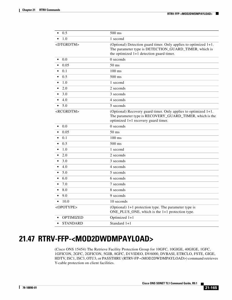
Chapter 21 RTRV CommandsRTRV-FFP-<MOD2DWDMPAYLOAD>
21.47 RTRV-FFP-<MOD2DWDMPAYLOAD>(Cisco ONS 15454) The Retrieve Facility Protection Group for 10GFC, 10GIGE, 40GIGE, 1GFC, 1GFICON, 2GFC, 2GFICON, 5GIB, 8GFC, D1VIDEO, DV6000, DVBASI, ETRCLO, FSTE, GIGE, HDTV, ISC1, ISC3, OTU3, or PASSTHRU (RTRV-FP-<MOD2DWDMPAYLOAD>) command retrieves Y-cable protection on client facilities.
• 0.5 500 ms
• 1.0 1 second
<DTGRDTM> (Optional) Detection guard timer. Only applies to optimized 1+1. The parameter type is DETECTION_GUARD_TIMER, which is the optimized 1+1 detection guard timer.
• 0.0 0 seconds
• 0.05 50 ms
• 0.1 100 ms
• 0.5 500 ms
• 1.0 1 second
• 2.0 2 seconds
• 3.0 3 seconds
• 4.0 4 seconds
• 5.0 5 seconds
<RCGRDTM> (Optional) Recovery guard timer. Only applies to optimized 1+1. The parameter type is RECOVERY_GUARD_TIMER, which is the optimized 1+1 recovery guard timer.
• 0.0 0 seconds
• 0.05 50 ms
• 0.1 100 ms
• 0.5 500 ms
• 1.0 1 second
• 2.0 2 seconds
• 3.0 3 seconds
• 4.0 4 seconds
• 5.0 5 seconds
• 6.0 6 seconds
• 7.0 7 seconds
• 8.0 8 seconds
• 9.0 9 seconds
• 10.0 10 seconds
<OPOTYPE> (Optional) 1+1 protection type. The parameter type is ONE_PLUS_ONE, which is the 1+1 protection type.
• OPTIMIZED Optimized 1+1
• STANDARD Standard 1+1
21-165Cisco ONS SONET TL1 Command Guide, R9.1
78-18890-01

Chapter 21 RTRV CommandsRTRV-FFP-<MOD2DWDMPAYLOAD>
Usage Guidelines None
Category DWDM
Security Retrieve
Input Format RTRV-FFP-<MOD2DWDMPAYLOAD>:[<TID>]:<SRC>:<CTAG>[::::];
Input Example RTRV-FFP-HDTV:CISCO:FAC-1-1-1:100;
Input Parameters
Output Format SID DATE TIMEM CTAG COMPLD “<AIDUNIONID>,<AIDUNIONID1>::[PROTTYPE=<PROTTYPE>],[PROTID=<PROTID>], [RVRTV=<RVRTV>],[RVTM=<RVTM>],[PSDIRN=<PSDIRN>]”;
Output Example TID-000 1998-06-20 14:30:00M 001 COMPLD “FAC-1-1-1,FAC-2-1-1::PROTTYPE=Y-CABLE,PROTID=\“DC-METRO\”, RVRTV=N,RVTM=1.0,PSDIRN=BI”;
Output Parameters
<SRC> Source access identifier from the “26.15 FACILITY” section on page 35.
<AIDUNIONID> Access identifier from the “26.15 FACILITY” section on page 35.
<AIDUNIONID1> Access identifier from the “26.15 FACILITY” section on page 35.
<PROTTYPE> (Optional) The type of facility protection. The parameter type is PROTTYPE, which is the protection type for DWDM client facilities.
• Y-CABLE Y-cable protection for the client ports on TXP_MR_10G, MXP_2.5G_10G, TXP_MR_2.5G, and TXPP_MR_2.5G cards.
<PROTID> (Optional) Y-cable protection group identifier. PROTID is a string.
21-166Cisco ONS SONET TL1 Command Guide, R9.1
78-18890-01
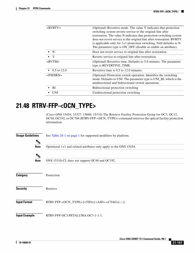
Chapter 21 RTRV CommandsRTRV-FFP-<OCN_TYPE>
21.48 RTRV-FFP-<OCN_TYPE>(Cisco ONS 15454, 15327, 15600, 15310) The Retrieve Facility Protection Group for OC3, OC12, OC48, OC192, or OC768 (RTRV-FFP-<OCN_TYPE>) command retrieves the optical facility protection information.
Usage Guidelines See Table 28-1 on page 1 for supported modifiers by platform.
Note Optimized 1+1 and related attributes only apply to the ONS 15454.
Note ONS 15310-CL does not support OC48 and OC192.
Category Protection
Security Retrieve
Input Format RTRV-FFP-<OCN_TYPE>:[<TID>]:<AID>:<CTAG>[::::];
Input Example RTRV-FFP-OC3:PETALUMA:OC3-1-1:1;
<RVRTV> (Optional) Revertive mode. The value Y indicates that protection switching system reverts service to the original line after restoration. The value N indicates that protection switching system does not revert service to the original line after restoration. RVRTV is applicable only for 1+1 protection switching. Null defaults to N. The parameter type is ON_OFF (disable or enable an attribute).
• N Does not revert service to original line after restoration.
• Y Reverts service to original line after restoration.
<RVTM> (Optional) Revertive time. Defaults to 5.0 minutes. The parameter type is REVERTIVE_TIME.
• 0.5 to 12.0 Revertive time is 0.5 to 12.0 minutes.
<PSDIRN> (Optional) Protection switch operation. Identifies the switching mode. Defaults to UNI. The parameter type is UNI_BI, which is the unidirectional and bidirectional switch operations.
• BI Bidirectional protection switching
• UNI Unidirectional protection switching
21-167Cisco ONS SONET TL1 Command Guide, R9.1
78-18890-01

Chapter 21 RTRV CommandsRTRV-FFP-<OCN_TYPE>
Input Parameters
Output Format SID DATE TIMEM CTAG COMPLD “<WORK>,<PROTECT>::[PROTTYPE=<PROTTYPE>],[PROTID=<PROTID>], [RVRTV=<RVRTV>],[RVTM=<RVTM>],[PSDIRN=<PSDIRN>],[VRGRDTM=<VRGRDTM>], [DTGRDTM=<DTGRDTM>],[RCGRDTM=<RCGRDTM>],[OPOTYPE=<OPOTYPE>]”;
Output Example TID-000 1998-06-20 14:30:00M 001 COMPLD “FAC-2-1,FAC-1-1::PROTTYPE=Y-CABLE,PROTID="PROT_NAME",RVRTV=Y,RVTM=1.0, PSDIRN=BI,VRGRDTM=0.5,DTGRDTM=1.0,RCGRDTM=1.0,OPOTYPE=OPTIMIZED”;
Output Parameters
<AID> Access identifier from the “26.15 FACILITY” section on page 35.
<WORK> Access identifier from the “26.15 FACILITY” section on page 35. Identifies the working port.
<PROTECT> Access identifier from the “26.15 FACILITY” section on page 35. Identifies the protection port.
<PROTTYPE> (Optional) Protection group type. Applicable only to DWDM cards. The parameter type is PROTTYPE, which is the protection type for DWDM client facilities.
• Y-CABLE Y-cable protection for the client ports on TXP_MR_10G, MXP_2.5G_10G, TXP_MR_2.5G, and TXPP_MR_2.5G cards.
<PROTID> (Optional) Free-form text string name given to the 1+1 protection group. PROTID is a string.
<RVRTV> (Optional) Revertive mode. The value Y indicates that protection switching system reverts service to the original line after restoration. The value N indicates that protection switching system does not revert service to the original line after restoration. RVRTV is applicable only for 1+1 protection switching. Defaults to N, non-revertive.
• N Does not revert service to original line after restoration.
• Y Reverts service to original line after restoration.
<RVTM> (Optional) Revertive time. Defaults to 5.0 minutes. The parameter type is REVERTIVE_TIME.
• 0.5 to 12.0 Revertive time is 0.5 to 12.0 minutes.
<PSDIRN> (Optional) Protection switch operation. Identifies the switching mode. Defaults to UNI. The parameter type is TRANS_MODE, which is the G1000 transponder mode.
• BI Bidirectional
• NONE Not in transponder mode
• UNI Unidirectional
21-168Cisco ONS SONET TL1 Command Guide, R9.1
78-18890-01

Chapter 21 RTRV CommandsRTRV-FFP-<OCN_TYPE>
<VRGRDTM> (Optional) Verification guard timer. Only applies to optimized 1+1. The parameter type is VERIFICATION_GUARD_TIMER, which is the optimized 1+1 verification guard timer.
• 0.5 500 ms
• 1.0 1 second
<DTGRDTM> (Optional) Detection guard timer. Only applies to optimized 1+1. The parameter type is DETECTION_GUARD_TIMER, which is the optimized 1+1 detection guard timer.
• 0.0 0 seconds
• 0.05 50 ms
• 0.1 100 ms
• 0.5 500 ms
• 1.0 1 second
• 2.0 2 seconds
• 3.0 3 seconds
• 4.0 4 seconds
• 5.0 5 seconds
<RCGRDTM> (Optional) Recovery guard timer. Only applies to optimized 1+1. The parameter type is RECOVERY_GUARD_TIMER, which is the optimized 1+1 recovery guard timer.
• 0.0 0 seconds
• 0.05 50 ms
• 0.1 100 ms
• 0.5 500 ms
• 1.0 1 second
• 2.0 2 seconds
• 3.0 3 seconds
• 4.0 4 seconds
• 5.0 5 seconds
• 6.0 6 seconds
• 7.0 7 seconds
• 8.0 8 seconds
• 9.0 9 seconds
• 10.0 10 seconds
<OPOTYPE> (Optional) 1+1 protection type. The parameter type is ONE_PLUS_ONE, which is the 1+1 protection type.
• OPTIMIZED Optimized 1+1
• STANDARD Standard 1+1
21-169Cisco ONS SONET TL1 Command Guide, R9.1
78-18890-01

Chapter 21 RTRV CommandsRTRV-FFP-OCH
21.49 RTRV-FFP-OCH(Cisco ONS 15454) The Retrieve Facility Protection Group Optical Channel (RTRV-FFP-OCH) command retrieves the protection group information for the TXP_MR_2.5G and TXPP_MR_2.5G card trunk port.
Usage Guidelines None
Category DWDM
Security Retrieve
Input Format RTRV-FFP-OCH:[<TID>]:<AID>:<CTAG>[::::];
Input Example RTRV-FFP-OCH:VA454-22:CHAN-2-2:100;
Input Parameters
Output Format SID DATE TIMEM CTAG COMPLD “<WORK>,<PROTECT>::[PROTTYPE=<PROTTYPE>],[PROTID=<PROTID>], [RVRTV=<RVRTV>],[RVTM=<RVTM>,[,PSDIRN=<PSDIRN>]”;
Output Example TID-000 1998-06-20 14:30:00M 001 COMPLD “CHAN-2-2,CHAN-2-3::PROTTYPE=SPLITTER,PROTID=\“TRUNK PROT\”,RVRTV=Y, RVTM=1.0,PSDIRN=UNI”;
Output Parameters
<AID> Access identifier from the “26.8 CHANNEL” section on page 19.
<WORK> The working port access identifier from the “26.8 CHANNEL” section on page 19.
<PROTECT> The protected port access identifier from the “26.8 CHANNEL” section on page 19.
<PROTTYPE> (Optional) Protection group type. PROTTYPE is a string.
<PROTID> (Optional) Protection group name. PROTID is a string.
21-170Cisco ONS SONET TL1 Command Guide, R9.1
78-18890-01

Chapter 21 RTRV CommandsRTRV-FFP-OTS
21.50 RTRV-FFP-OTS(Cisco ONS 15454) The Retrieve Facility Protection Group OTS (RTRV-FFP-OTS) command retrieves the protection group information for the TXP_MR_2.5G and TXPP_MR_2.5G card trunk port and OTU2-XP and optical protection switching unit.
Usage Guidelines None
Category DWDM
Security Retrieve
Input Format RTRV-FFP-OTS:[<TID>]:<AID>:<CTAG>[::::];
Input Example RTRV-FFP-OTS:VA454-22:CHAN-2-2:100;
Input Parameters
<RVRTV> (Optional) Revertive mode. The value Y indicates that protection switching system reverts service to the original line after restoration. The value N indicates that protection switching system does not revert service to the original line after restoration. RVRTV is applicable only for 1+1 protection switching. Defaults to N. Null defaults to N. The parameter type is ON_OFF (disable or enable an attribute).
• N Does not revert service to original line after restoration.
• Y Reverts service to original line after restoration.
<RVTM> (Optional) Revertive time. The parameter type is REVERTIVE_TIME.
• 0.5 to 12.0 Revertive time is 0.5 to 12.0 minutes.
<PSDIRN> (Optional) Protection switch operation. Direction of reversion. The parameter type is UNI_BI, which is the unidirectional and bidirectional switch operations.
• BI Bidirectional protection switching
• UNI Unidirectional protection switching
<AID> Access identifier from the “26.8 CHANNEL” section on page 19.
21-171Cisco ONS SONET TL1 Command Guide, R9.1
78-18890-01

Chapter 21 RTRV CommandsRTRV-FSTE
Output Format SID DATE TIMEM CTAG COMPLD “<WORK>,<PROTECT>::[PROTTYPE=<PROTTYPE>],[PROTID=<PROTID>], [RVRTV=<RVRTV>],[RVTM=<RVTM>,[,PSDIRN=<PSDIRN>]”;
Output Example TID-000 1998-06-20 14:30:00M 001 COMPLD “CHAN-2-2,CHAN-2-3::PROTTYPE=SPLITTER,PROTID=\“TRUNK PROT\”,RVRTV=Y, RVTM=1.0,PSDIRN=UNI”;
Output Parameters
21.51 RTRV-FSTE(Cisco ONS 15310-CL, Cisco ONS 15310-MA, and Cisco ONS 15454) The Retrieve Fast Ethernet (RTRV-FSTE) command retrieves the front-end port information of a Fast Ethernet (10/100 Mbps) card. MTU is not displayed for the ML-100T-8 and CE-100T-8 cards.
<WORK> The working port access identifier from the “26.8 CHANNEL” section on page 19.
<PROTECT> The protected port access identifier from the “26.8 CHANNEL” section on page 19.
<PROTTYPE> (Optional) Protection group type. PROTTYPE is a string.
<PROTID> (Optional) Protection group name. PROTID is a string.
<RVRTV> (Optional) Revertive mode. The value Y indicates that protection switching system reverts service to the original line after restoration. The value N indicates that protection switching system does not revert service to the original line after restoration. RVRTV is applicable only for 1+1 protection switching. Defaults to N. Null defaults to N. The parameter type is ON_OFF (disable or enable an attribute).
• N Does not revert service to original line after restoration.
• Y Reverts service to original line after restoration.
<RVTM> (Optional) Revertive time. The parameter type is REVERTIVE_TIME.
• 0.5 to 12.0 Revertive time is 0.5 to 12.0 minutes.
<PSDIRN> (Optional) Protection switch operation. Direction of reversion. The parameter type is UNI_BI, which is the unidirectional and bidirectional switch operations.
• BI Bidirectional protection switching
• UNI Unidirectional protection switching
21-172Cisco ONS SONET TL1 Command Guide, R9.1
78-18890-01

Chapter 21 RTRV CommandsRTRV-FSTE
Usage Guidelines This command retrieves the front-end port information of Fast Ethernet (10/100 Mbps) cards. MTU is not displayed for CE-100T-8 and ML-100T-8. However, RTRV-POS will display the MTU, which is common for front and backend ports.
The SELECTIVEAUTO parameter is applicable only when EXPSPEED and EXPDUPLEX are not set to AUTO mode.
Category Ports
Security Retrieve
Input Format RTRV-FSTE:[<TID>]:<AID>:<CTAG>;
Input Example RTRV-FSTE:TID:FAC-1-1:CTAG;
Input Parameters
Output Format SID DATE TIMEM CTAG COMPLD“<AID>:[<ROLE>],[<STATUS>]:[<ADMINSTATE>],[<LINKSTATE>],[<MTU>],[<FLOWCTRL>],[<OPTICS>],[<DUPLEX>],[<SPEED>],[<FLOW>],[<EXPDUPLEX>],[<EXPSPEED>],[<VLANCOSTHRESHOLD>],[<IPTOSTHRESHOLD>],[<NAME>],[<SUPPRESS>],[<SOAK>],[<SOAKLEFT>],[<SELECTIVEAUTO>],[LIENABLE=<LIENABLE>],[<LITIMER>],[<LBCL>],[<OPT>],[<OPR>],[<FREQ>],[<LOSSB>],[<ACTFLOW>],[<ACTDUPLEX>],[<ACTSPEED>]:<PST>,[<SST>]”;
Output Example TID-000 1998-06-20 14:30:00M 001 COMPLDTID-000 1998-06-20 14:30:00M 001 COMPLD"FAC-2-1:,:LINKSTATE=DOWN,FLOWCTRL=NONE,DUPLEX=AUTO,SPEED=AUTO,FLOW=Y,EXPDUPLEX=AUTO,EXPSPEED=AUTO,VLANCOS=7,IPTOS=255,SOAK=32,SELECTIVEAUTO=N,LIENABLE=Y,LITIMER=200,:OOS-MA,DSBLD";
Output Parameters
<AID> Access identifier from the “26.15 FACILITY” section on page 35.
<AID> Access identifier from the “26.15 FACILITY” section on page 35.
<ROLE> Identifies the port role in a Y-cable protection scheme. The parameter type is SIDE, which is the role the unit is playing in the protection group.
<STATUS> Identifies a port status in a Y-cable protection scheme. The parameter type is STATUS, which is the status of the unit in the protection pair.
21-173Cisco ONS SONET TL1 Command Guide, R9.1
78-18890-01
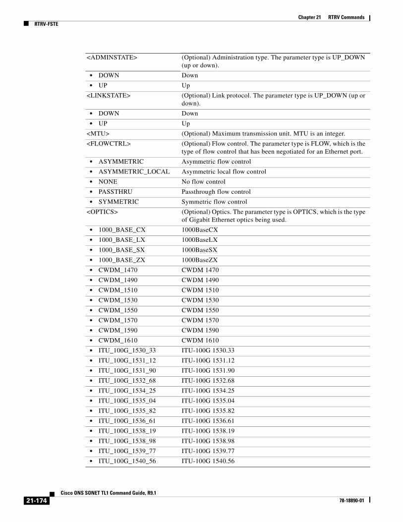
Chapter 21 RTRV CommandsRTRV-FSTE
<ADMINSTATE> (Optional) Administration type. The parameter type is UP_DOWN (up or down).
• DOWN Down
• UP Up
<LINKSTATE> (Optional) Link protocol. The parameter type is UP_DOWN (up or down).
• DOWN Down
• UP Up
<MTU> (Optional) Maximum transmission unit. MTU is an integer.
<FLOWCTRL> (Optional) Flow control. The parameter type is FLOW, which is the type of flow control that has been negotiated for an Ethernet port.
• ASYMMETRIC Asymmetric flow control
• ASYMMETRIC_LOCAL Asymmetric local flow control
• NONE No flow control
• PASSTHRU Passthrough flow control
• SYMMETRIC Symmetric flow control
<OPTICS> (Optional) Optics. The parameter type is OPTICS, which is the type of Gigabit Ethernet optics being used.
• 1000_BASE_CX 1000BaseCX
• 1000_BASE_LX 1000BaseLX
• 1000_BASE_SX 1000BaseSX
• 1000_BASE_ZX 1000BaseZX
• CWDM_1470 CWDM 1470
• CWDM_1490 CWDM 1490
• CWDM_1510 CWDM 1510
• CWDM_1530 CWDM 1530
• CWDM_1550 CWDM 1550
• CWDM_1570 CWDM 1570
• CWDM_1590 CWDM 1590
• CWDM_1610 CWDM 1610
• ITU_100G_1530_33 ITU-100G 1530.33
• ITU_100G_1531_12 ITU-100G 1531.12
• ITU_100G_1531_90 ITU-100G 1531.90
• ITU_100G_1532_68 ITU-100G 1532.68
• ITU_100G_1534_25 ITU-100G 1534.25
• ITU_100G_1535_04 ITU-100G 1535.04
• ITU_100G_1535_82 ITU-100G 1535.82
• ITU_100G_1536_61 ITU-100G 1536.61
• ITU_100G_1538_19 ITU-100G 1538.19
• ITU_100G_1538_98 ITU-100G 1538.98
• ITU_100G_1539_77 ITU-100G 1539.77
• ITU_100G_1540_56 ITU-100G 1540.56
21-174Cisco ONS SONET TL1 Command Guide, R9.1
78-18890-01

Chapter 21 RTRV CommandsRTRV-FSTE
• ITU_100G_1542_14 ITU-100G 1542.14
• ITU_100G_1542_94 ITU-100G 1542.94
• ITU_100G_1543_73 ITU-100G 1543.73
• ITU_100G_1544_53 ITU-100G 1544.53
• ITU_100G_1546_12 ITU-100G 1546.12
• ITU_100G_1546_92 ITU-100G 1546.92
• ITU_100G_1547_72 ITU-100G 1547.72
• ITU_100G_1548_51 ITU-100G 1548.51
• ITU_100G_1550_12 ITU-100G 1550.12
• ITU_100G_1550_92 ITU-100G 1550.92
• ITU_100G_1551_72 ITU-100G 1551.72
• ITU_100G_1552_52 ITU-100G 1552.52
• ITU_100G_1554_13 ITU-100G 1554.13
• ITU_100G_1554_94 ITU-100G 1554.94
• ITU_100G_1555_75 ITU-100G 1555.75
• ITU_100G_1556_55 ITU-100G 156.55
• ITU_100G_1558_17 ITU-100G 1558.17
• ITU_100G_1558_98 ITU-100G 1558.98
• ITU_100G_1559_79 ITU-100G 1559.79
• ITU_100G_1560_61 ITU-100G 1560.61
• UNKNOWN Unknown Optical Type
• UNPLUGGED Unplugged
<DUPLEX> (Optional) Duplex mode. The parameter type is ETHER_DUPLEX (duplex mode).
• AUTO Auto mode
• FULL Full mode
• HALF Half mode
<SPEED> (Optional) Speed. The parameter type is ETHER_SPEED, which is the Ethernet speed.
• 100_MBPS 100 Mbps
• 10_GBPS 10 Gbps
• 10_MBPS 10 Mbps
• 1_GBPS 1 Gbps
• AUTO Auto
<FLOW> (Optional) Flow. The parameter type is ON_OFF (disable or enable an attribute).
• N Disable an attribute.
• Y Enable an attribute.
<EXPDUPLEX> (Optional) Ethernet duplex mode. The parameter type is ETHER_DUPLEX, which is the duplex mode.
• AUTO Auto mode
• FULL Full mode
21-175Cisco ONS SONET TL1 Command Guide, R9.1
78-18890-01

Chapter 21 RTRV CommandsRTRV-FSTE
• HALF Half mode
<EXPSPEED> (Optional) Expected speed. Due to the auto-negotiation feature, actual speed may differ from expected speed. The parameter type is ETHER_SPEED, which is the Ethernet speed.
• 100_MBPS 100 Mbps
• 10_GBPS 10 Gbps
• 10_MBPS 10 Mbps
• 1_GBPS 1 Gbps
• AUTO Auto
<SELECTIVEAUTO> (Optional) Selective auto-negotiation. The parameter is Y or N (enable or disable auto-negotiation) This indicates selective auto-negotiation of EXPSPEED and EXPDUPLEX only.
• Y Enable selective auto-negotiation.
• N Disable selective auto-negotiation. The default value is N.
<VLANCOS> (Optional) Priority queuing threshold based on VLAN class of service of incoming Ethernet packets. VLANCOS is an integer in the range 0 to 7. Defaults to 7.
<IPTOS> (Optional) Priority queuing threshold based on IP type of service of incoming Ethernet packets. IPTOS is an integer in the range 0 to 255. Defaults to 255.
<NAME> (Optional) Facility name. NAME is a string.
<SUPPRESS> Pre-service alarm flag for data ports.
• ON Enable suppress.
• OFF Disable suppress. Default is Off.
<SOAK> (Optional) Locked-AutomaticInService to Unlocked transition soak time as measured in 15-minute intervals. SOAK is an integer.
<SOAKLEFT> (Optional) Time remaining for the transition from Locked-AutomaticInService to Unlocked measured in 1 minute intervals. The format is HH-MM where HH ranges from 00 to 48 and MM ranges from 00 to 59. Rules for SOAKLEFT are as follows:
• When the port is in Locked, Locked_Maintenance or Unlocked state, the parameter will not appear.
• When the port is in Locked_AutomaticInService but the countdown has not started due to a fault signal, the value will be SOAKLEFT=NOT-STARTED.
• When the port is in Locked_AutomaticInService state and the countdown has started, the value will be shown in HH-MM format.
<LIENABLE> (Optional) Enable or Disable link integrity timer. Takes either Y or N. Value Y enables the LITIMER and value N disables LITIMER.
By default LITIMER is enabled.
Note The LIENABLE parameter is supported on only CE-1000-4 and CE-1000T-8 cards on the 15454; the LIENABLE parameter is supported on only the CE-1000T-8 card on the 15310-MA.
21-176Cisco ONS SONET TL1 Command Guide, R9.1
78-18890-01

Chapter 21 RTRV CommandsRTRV-FTPSERVER
21.52 RTRV-FTPSERVER(Cisco ONS 15310-CL, Cisco ONS 15310-MA, Cisco ONS 15454, and Cisco ONS 15600) The Retrieve FTP Server (RTRV-FTPSERVER) command retrieves FTP server entries.
Usage Guidelines FTP server entries cannot be retrieved using the TIMER filter.
Category ENE
Security Retrieve
Input Format RTRV-FTPSERVER:[<TID>]::<CTAG>:::[IPADDR=<IPADDR>],[IPMASK=<IPMASK>],[ENABLE=<ENABLE>];
<LITIMER> (Optional) Link integrity timer duration in the range between 200 ms and 10000 ms in multiples on 100 ms.
Note The LITIMER parameter is supported on only CE-1000-4 and CE-1000T-8 cards on the 15454; the LITIMER parameter is supported on only the CE-1000T-8 card on the 15310-MA.
<PSTPSTQ> Administrative state in the PST_PSTQ format. The parameter type is PST_PSTQ, which is the service state of the entity described by the PST and the PSTQ.
• Unlocked-Enabled In service and normal
• Unlocked-Disabled Out of service and autonomous
• Locked-Disabled Out of service, autonomous and management
• Locked-Enabled Out of service and management
<SSTQ> (Optional) Secondary state of the entity. the parameter type is SST, which provides additional information pertaining to PST and PSTQ.
• AutomaticInService Automatic in service
• Disabled Disabled
• Loopback Loopback
• MismatchofEquipmentAlarm Mismatch of equipment and attributes
• Maintenance Maintenance mode
• OutOfGroup Out of group
• SoftwareDownload Software downloading
• Unassigned Unassigned
• NotInstalled Unequipped
21-177Cisco ONS SONET TL1 Command Guide, R9.1
78-18890-01

Chapter 21 RTRV CommandsRTRV-G1000
Input Example RTRV-FTPSERVER:::A:::IPADDR=10.20.30.40
Input Parameters
Output Format SID DATE TIMEM CTAG COMPLD",:IPADDR=<IPADDR>,IPMASK=<IPMASK>, ENABLE=<ENABLE>,TIMER=<TIMER>";
Output Example SID DATE TIMEM CTAG COMPLD",:IPADDR=10.20.30.40,IPMASK=255.0.0.0, ENABLE=Y,TIMER=10";
Output Parameters
21.53 RTRV-G1000(Cisco ONS 15454) The Retrieve G1000 Facility (RTRV-G1000) command retrieves the G1000 facilities configuration.
Usage Guidelines None
Category Ports
Security Retrieve
<IPADDR> Specifies the IP address of the FTP server.
<IPMASK> Specifies the subnet mask of the FTP server.
<ENABLE> Specifies the enable/disable option of the FTP server. The parameter type is ON_OFF (disable or enable an attribute).
• N Disable an attribute.
• Y Enable an attribute.
<IPADDR> Specifies the IP address of the FTP Server.
<IPMASK> Specifies the subnet mask of the FTP Server.
<ENABLE> Specifies the enable/disable option of the FTP Server. The parameter type is ON_OFF (disable or enable an attribute).
• N Disable an attribute.
• Y Enable an attribute.
<TIMER> Specifies the timeout value of the FTP Server in minutes.
21-178Cisco ONS SONET TL1 Command Guide, R9.1
78-18890-01
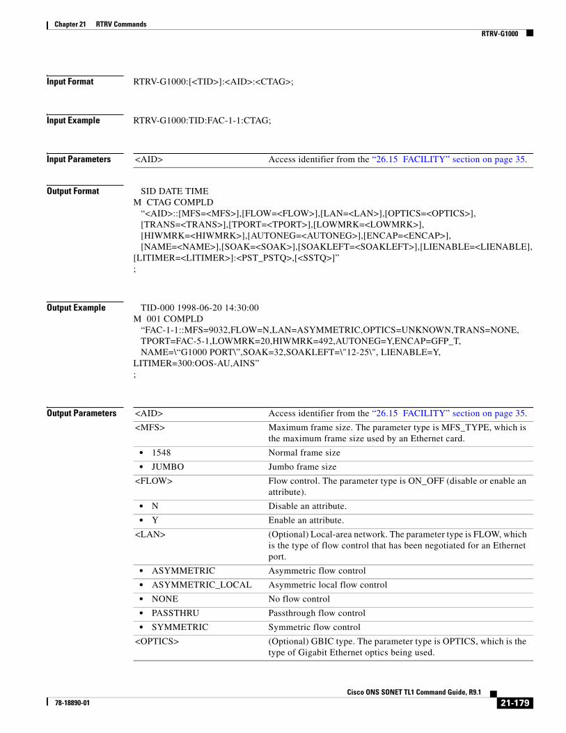
Chapter 21 RTRV CommandsRTRV-G1000
Input Format RTRV-G1000:[<TID>]:<AID>:<CTAG>;
Input Example RTRV-G1000:TID:FAC-1-1:CTAG;
Input Parameters
Output Format SID DATE TIMEM CTAG COMPLD “<AID>::[MFS=<MFS>],[FLOW=<FLOW>],[LAN=<LAN>],[OPTICS=<OPTICS>], [TRANS=<TRANS>],[TPORT=<TPORT>],[LOWMRK=<LOWMRK>], [HIWMRK=<HIWMRK>],[AUTONEG=<AUTONEG>],[ENCAP=<ENCAP>], [NAME=<NAME>],[SOAK=<SOAK>],[SOAKLEFT=<SOAKLEFT>],[LIENABLE=<LIENABLE],[LITIMER=<LITIMER>]:<PST_PSTQ>,[<SSTQ>]”;
Output Example TID-000 1998-06-20 14:30:00M 001 COMPLD “FAC-1-1::MFS=9032,FLOW=N,LAN=ASYMMETRIC,OPTICS=UNKNOWN,TRANS=NONE, TPORT=FAC-5-1,LOWMRK=20,HIWMRK=492,AUTONEG=Y,ENCAP=GFP_T, NAME=\“G1000 PORT\”,SOAK=32,SOAKLEFT=\"12-25\", LIENABLE=Y,LITIMER=300:OOS-AU,AINS”;
Output Parameters
<AID> Access identifier from the “26.15 FACILITY” section on page 35.
<AID> Access identifier from the “26.15 FACILITY” section on page 35.
<MFS> Maximum frame size. The parameter type is MFS_TYPE, which is the maximum frame size used by an Ethernet card.
• 1548 Normal frame size
• JUMBO Jumbo frame size
<FLOW> Flow control. The parameter type is ON_OFF (disable or enable an attribute).
• N Disable an attribute.
• Y Enable an attribute.
<LAN> (Optional) Local-area network. The parameter type is FLOW, which is the type of flow control that has been negotiated for an Ethernet port.
• ASYMMETRIC Asymmetric flow control
• ASYMMETRIC_LOCAL Asymmetric local flow control
• NONE No flow control
• PASSTHRU Passthrough flow control
• SYMMETRIC Symmetric flow control
<OPTICS> (Optional) GBIC type. The parameter type is OPTICS, which is the type of Gigabit Ethernet optics being used.
21-179Cisco ONS SONET TL1 Command Guide, R9.1
78-18890-01

Chapter 21 RTRV CommandsRTRV-G1000
• 1000_BASE_CX 1000 Base CX
• 1000_BASE_LX 1000 Base LX
• 1000_BASE_SX 1000 Base SX
• 1000_BASE_ZX 1000 Base ZX
• CWDM_1470 CWDM 1470
• CWDM_1490 CWDM 1490
• CWDM_1510 CWDM 1510
• CWDM_1530 CWDM 1530
• CWDM_1550 CWDM 1550
• CWDM_1570 CWDM 1570
• CWDM_1590 CWDM 1590
• CWDM_1610 CWDM 1610
• ITU_100G_1530_33 ITU-100G 1530.33
• ITU_100G_1531_12 ITU-100G 1531.12
• ITU_100G_1531_90 ITU-100G 1531.90
• ITU_100G_1532_68 ITU-100G 1532.68
• ITU_100G_1534_25 ITU-100G 1534.25
• ITU_100G_1535_04 ITU-100G 1535.04
• ITU_100G_1535_82 ITU-100G 1535.82
• ITU_100G_1536_61 ITU-100G 1536.61
• ITU_100G_1538_19 ITU-100G 1538.19
• ITU_100G_1538_98 ITU-100G 1538.98
• ITU_100G_1539_77 ITU-100G 1539.77
• ITU_100G_1540_56 ITU-100G 1540.56
• ITU_100G_1542_14 ITU-100G 1542.14
• ITU_100G_1542_94 ITU-100G 1542.94
• ITU_100G_1543_73 ITU-100G 1543.73
• ITU_100G_1544_53 ITU-100G 1544.53
• ITU_100G_1546_12 ITU-100G 1546.12
• ITU_100G_1546_92 ITU-100G 1546.92
• ITU_100G_1547_72 ITU-100G 1547.72
• ITU_100G_1548_51 ITU-100G 1548.51
• ITU_100G_1550_12 ITU-100G 1550.12
• ITU_100G_1550_92 ITU-100G 1550.92
• ITU_100G_1551_72 ITU-100G 1551.72
• ITU_100G_1552_52 ITU-100G 1552.52
• ITU_100G_1554_13 ITU-100G 1554.13
• ITU_100G_1554_94 ITU-100G 1554.94
• ITU_100G_1555_75 ITU-100G 1555.75
• ITU_100G_1556_55 ITU-100G 156.55
• ITU_100G_1558_17 ITU-100G 1558.17
21-180Cisco ONS SONET TL1 Command Guide, R9.1
78-18890-01

Chapter 21 RTRV CommandsRTRV-G1000
• ITU_100G_1558_98 ITU-100G 1558.98
• ITU_100G_1559_79 ITU-100G 1559.79
• ITU_100G_1560_61 ITU-100G 1560.61
• UNKNOWN Unknown Optical Type
• UNPLUGGED Unplugged
<TRANS> (Optional) Transponder mode. The parameter type is TRANS_MODE, which is the G1000 transponder mode.
• BI Bidirectional
• NONE Not in transponder mode
• UNI Unidirectional
<TPORT> (Optional) Transponding port access identifier from the “26.15 FACILITY” section on page 35.
<LOWMRK> (Optional) Low watermark value. LOWMRK is an integer.
<HIWMRK> (Optional) High watermark value. HIWMRK is an integer.
<AUTONEG> (Optional) Automatic negotiation. The parameter type is ON_OFF (disable or enable an attribute).
• N Disable an attribute.
• Y Enable an attribute.
<ENCAP> (Optional) Frame encapsulation type. The parameter type is ENCAP, which is the frame encapsulation type.
• GFP_F GFP frame mode
• GFP_T GFP transparent mode
• HDLC HDLC frame mode
• HDLC_LEX HDLC LAN extension frame mode
• HDLC_X86 HDLC X.86 frame mode
<NAME> (Optional) Facility name. NAME is a string.
<SOAK> (Optional) OOS-AINS to IS transition soak time as measured in 15-minute intervals. SOAK is an integer.
<SOAKLEFT> (Optional) Time remaining for the transition from OOS-AINS to IS measured in 1-minute intervals. The format is HH-MM where HH ranges from 00 to 48 and MM ranges from 00 to 59. Rules for SOAKLEFT are as follows:
• When the port is in OOS, OOS_MT or IS state, the parameter will not appear.
• When the port is in OOS_AINS state but the countdown has not started due to a fault signal, the value will be SOAKLEFT=NOT-STARTED.
• When the port is in OOS_AINS state and the countdown has started, the value will be shown in HH-MM format.
21-181Cisco ONS SONET TL1 Command Guide, R9.1
78-18890-01

Chapter 21 RTRV CommandsRTRV-GFP
21.54 RTRV-GFP(Cisco ONS 15310-CL, Cisco ONS 15310-MA, Cisco ONS 15454, and Cisco ONS 15600) The Retrieve Generic Framing Protocol (RTRV-GFP) command retrieves GFP information for the ONS 15454 CE-100T-8 and CE-1000-4 cards, the ONS 15454 FC_MR-4 card, and the ONS 15310-CL CE-100T-8 card.
Usage Guidelines None
Category Ports
<LIENABLE> (Optional) Enable or Disable link integrity timer. Takes either Y or N. Value Y enables the LITIMER and value N disables LITIMER.
By default LITIMER is enabled.
Note The LIENABLE parameter is supported on only CE-1000-4 and CE-1000T-8 cards on the 15454; the LIENABLE parameter is supported on only the CE-1000T-8 card on the 15310-MA.
<LITIMER> (Optional) Link integrity timer duration in the range between 200 ms and 10000 ms in multiples on 100 ms.
Note The LITIMER parameter is supported on only CE-1000-4 and CE-1000T-8 cards on the 15454; the LITIMER parameter is supported on only the CE-1000T-8 card on the 15310-MA.
<PSTPSTQ> Administrative state in the PST-PSTQ format. The parameter type is PST_PSTQ, which is the service state of the entity described by the PST and PSTQ.
• IS-NR In Service and Normal
• OOS-AU Out of Service and Autonomous
• OOS-AUMA Out of Service and Autonomous Management
• OOS-MA Out of Service and Management
<SSTQ> Secondary state. The parameter type is SST, which provides additional information pertaining to PST and PSTQ.
• AINS Automatic In-Service
• DSBLD Disabled
• LPBK Loopback
• MEA Mismatch of Equipment
• MT Maintenance
• OOG Out of Group
• SWDL Software Download
• UAS Unassigned
• UEQ Unequipped
21-182Cisco ONS SONET TL1 Command Guide, R9.1
78-18890-01

Chapter 21 RTRV CommandsRTRV-GFP
Security Retrieve
Input Format RTRV-GFP:[<TID>]:<SRC>:<CTAG>;
Input Example RTRV-GFP:CISCO:FAC-1-1:123;
Input Parameters
Output Format SID DATE TIMEM CTAG COMPLD “<AID>::[FCS=<FCS>],[AUTOTHGFPBUF=<AUTOTHGFPBUF>], [GFPBUF=<GFPBUF>],[FILTER=<FILTER>]”;
Output Example TID-000 1998-06-20 14:30:00M 001 COMPLD “FAC-1-1::FCS=FCS-32,AUTOTHGFPBUF=Y,GFPBUF=16,FILTER=EGRESS”;
Output Parameters
<SRC> Source access identifier from the “26.15 FACILITY” section on page 35.
Note VFAC AID is used for the CE-100T-8 cards on 15310-CL and 15454. ML-100T-8 GFP management is done by the Cisco IOS CLI and not by the TL1 interface. FAC AID is used for ONS 15454 FC_MR-4
<AID> Access identifier from the “26.15 FACILITY” section on page 35.
<FCS> (Optional) Payload frame check sequence. The parameter type is FCS, which is the frame check sequence.
• FCS-16 Frame check sequencing using 16 bits
• FCS-32 Frame check sequencing using 32 bits
• NONE No frame check sequence
<AUTOTHGFPBUF> (Optional) Flag used to indicate whether PDI-P should be generated on the outgoing VT-structured STSs. The parameter type is ON_OFF (disable or enable an attribute).
• N Disable an attribute.
• Y Enable an attribute.
<GFPBUF> (Optional) GFPBUF is an integer.
<FILTER> (Optional) Parameter type is GFP_FILTER, which is the filter.
• EGRESS Activate filter on egress port.
• NONE Turn off filter.
21-183Cisco ONS SONET TL1 Command Guide, R9.1
78-18890-01

Chapter 21 RTRV CommandsRTRV-GIGE
21.55 RTRV-GIGE(Cisco ONS 15454, ONS 15600) The Retrieve Gigabit (GIGE, 10GIGE) Ethernet (RTRV-GIGE) command retrieves the front-end port information for a 1 Gigabit Ethernet card.
Usage Guidelines None
Category Ports
Security Retrieve
Input Format RTRV-GIGE:[<TID>]:<AID>:<CTAG>;
Input Example RTRV-GIGE:TID:FAC-1-1:CTAG;
Input Parameters
Output Format SID DATE TIMEM CTAG COMPLD “<AID>:,,<ROLE>,<STATUS>:[ADMINSTATE=<ADMINSTATE>], [LINKSTATE=<LINKSTATE>],[MTU=<MTU>],[ENCAP=<ENCAP>], [FLOWCTRL=<FLOWCTRL>],[AUTONEG=<AUTONEG>],[HIWMRK=<HIWMRK>], [LOWMRK=<LOWMRK>],[OPTICS=<OPTICS>],[DUPLEX=<DUPLEX>], [SPEED=<SPEED>],[NAME=<NAME>],[FREQ=<FREQ>],[LOSSB=<LOSSB>], [SOAK=<SOAK>],[SOAKLEFT=<SOAKLEFT>],[LIENABLE=<LIENABLE>],[LITIMER=<LITIMER>]:<PST>,<SST>”;
Output Example TID-000 1998-06-20 14:30:00M 001 COMPLD “FAC-1-1:,,WORK,ACT:ADMINSTATE=DOWN,LINKSTATE=DOWN,MTU=1548, ENCAP=GFP-F,FLOWCTRL=SYMMETRIC,AUTONEG=Y,HIWMRK=485,LOWMRK=25, OPTICS=1000_BASE_SX,DUPLEX=AUTO,SPEED=AUTO,NAME=`"GIGEPORT\", FREQ=1550,LOSSB=SX,SOAK=32, SOAKLEFT=\"12-22\",LIENABLE=Y, LITIMER=300:IS,AINS”;
<AID> Access identifier from the “26.15 FACILITY” section on page 35.
21-184Cisco ONS SONET TL1 Command Guide, R9.1
78-18890-01

Chapter 21 RTRV CommandsRTRV-GIGE
Output Parameters <AID> Access identifier from the “26.15 FACILITY” section on page 35.
<ROLE> Identifies the port role in a Y-cable protection scheme. The parameter type is SIDE, which is the role the unit is playing in the protection group.
• PROT The entity is a protection unit in the protection group.
• WORK The entity is a working unit in the protection group.
<STATUS> Identifies a port status in a Y-cable protection scheme. The parameter type is STATUS, which is the status of the unit in the protection pair.
• ACT The entity is the active unit in the shelf.
• NA Status is unavailable.
• STBY The entity is the standby unit in the shelf.
<ADMINSTATE> (Optional) Administration type. The parameter type is UP_DOWN (up or down).
• DOWN Down
• UP Up
<LINKSTATE> (Optional) Link protocol. The parameter type is UP_DOWN (up or down).
• DOWN Down
• UP Up
<MTU> (Optional) Maximum transmission unit. MTU is an integer.
<ENCAP> (Optional) Encapsulation frame type. The parameter type is ENCAP, which is the frame encapsulation type.
• GFP_F GFP Frame Mode
• GFP_T GFP Transparent Mode
• HDLC HDLC Frame Mode
• HDLC_LEX HDLC LAN Extension Frame Mode
• HDLC_X86 HDLC X.86 Frame Mode
<FLOWCTRL> (Optional) Flow control. The parameter type is FLOW, which is the type of flow control that has been negotiated for an Ethernet port.
• ASYMMETRIC Asymmetric flow control
• ASYMMETRIC_LOCAL Asymmetric local flow control
• NONE No flow control
• PASSTHRU Passthrough flow control
• SYMMETRIC Symmetric flow control
<AUTONEG> (Optional) Automatic negotiation. The parameter type is ON_OFF (disable or enable an attribute).
• N Disable an attribute.
• Y Enable an attribute.
<LOWMRK> (Optional) Low watermark value. LOWMRK is an integer.
<HIWMRK> (Optional) High watermark value. HIWMRK is an integer.
<OPTICS> (Optional) Optics type. The parameter type is OPTICS, which is the type of Gigabit Ethernet optics being used.
21-185Cisco ONS SONET TL1 Command Guide, R9.1
78-18890-01
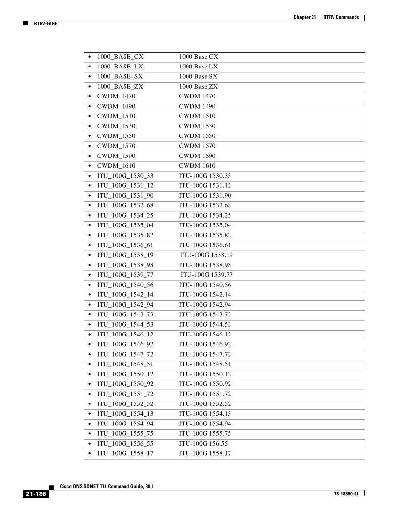
Chapter 21 RTRV CommandsRTRV-GIGE
• 1000_BASE_CX 1000 Base CX
• 1000_BASE_LX 1000 Base LX
• 1000_BASE_SX 1000 Base SX
• 1000_BASE_ZX 1000 Base ZX
• CWDM_1470 CWDM 1470
• CWDM_1490 CWDM 1490
• CWDM_1510 CWDM 1510
• CWDM_1530 CWDM 1530
• CWDM_1550 CWDM 1550
• CWDM_1570 CWDM 1570
• CWDM_1590 CWDM 1590
• CWDM_1610 CWDM 1610
• ITU_100G_1530_33 ITU-100G 1530.33
• ITU_100G_1531_12 ITU-100G 1531.12
• ITU_100G_1531_90 ITU-100G 1531.90
• ITU_100G_1532_68 ITU-100G 1532.68
• ITU_100G_1534_25 ITU-100G 1534.25
• ITU_100G_1535_04 ITU-100G 1535.04
• ITU_100G_1535_82 ITU-100G 1535.82
• ITU_100G_1536_61 ITU-100G 1536.61
• ITU_100G_1538_19 ITU-100G 1538.19
• ITU_100G_1538_98 ITU-100G 1538.98
• ITU_100G_1539_77 ITU-100G 1539.77
• ITU_100G_1540_56 ITU-100G 1540.56
• ITU_100G_1542_14 ITU-100G 1542.14
• ITU_100G_1542_94 ITU-100G 1542.94
• ITU_100G_1543_73 ITU-100G 1543.73
• ITU_100G_1544_53 ITU-100G 1544.53
• ITU_100G_1546_12 ITU-100G 1546.12
• ITU_100G_1546_92 ITU-100G 1546.92
• ITU_100G_1547_72 ITU-100G 1547.72
• ITU_100G_1548_51 ITU-100G 1548.51
• ITU_100G_1550_12 ITU-100G 1550.12
• ITU_100G_1550_92 ITU-100G 1550.92
• ITU_100G_1551_72 ITU-100G 1551.72
• ITU_100G_1552_52 ITU-100G 1552.52
• ITU_100G_1554_13 ITU-100G 1554.13
• ITU_100G_1554_94 ITU-100G 1554.94
• ITU_100G_1555_75 ITU-100G 1555.75
• ITU_100G_1556_55 ITU-100G 156.55
• ITU_100G_1558_17 ITU-100G 1558.17
21-186Cisco ONS SONET TL1 Command Guide, R9.1
78-18890-01

Chapter 21 RTRV CommandsRTRV-GIGE
• ITU_100G_1558_98 ITU-100G 1558.98
• ITU_100G_1559_79 ITU-100G 1559.79
• ITU_100G_1560_61 ITU-100G 1560.61
• UNKNOWN Unknown Optical Type
• UNPLUGGED Unplugged
<DUPLEX> (Optional) Duplex mode. The parameter type is ETHER_DUPLEX, which is the duplex mode.
• AUTO Auto mode
• FULL Full mode
• HALF Half mode
<SPEED> (Optional) Speed. The parameter type is ALS_MODE, which is the automatic laser shutdown mode.
• AUTO Automatic
• DISABLED Disabled
• MAN Manual
• MAN-RESTART Manual restart for test
<NAME> (Optional) Facility name. NAME is a string.
<FREQ> (Optional) Parameter type is OPTICAL_WLEN (optical wavelength).
• 1310 Wavelength 1310
• 1470 Wavelength 1470
• 1490 Wavelength 1490
• 1510 Wavelength 1510
• 1528.77 Wavelength 1528.77
• 1529.55 Wavelength 1529.55
• 1529.94 Wavelength 1529.94
• 1530 Wavelength 1530
• 1530.33 Wavelength 1530.33
• 1530.73 Wavelength 1530.73
• 1531.12 Wavelength 1531.12
• 1531.51 Wavelength 1531.51
• 1531.90 Wavelength 1531.90
• 1532.29 Wavelength 1532.29
• 1532.68 Wavelength 1532.68
• 1533.07 Wavelength 1533.07
• 1533.47 Wavelength 1533.47
• 1533.86 Wavelength 1533.86
• 1534.25 Wavelength 1534.25
• 1534.64 Wavelength 1534.64
• 1535.04 Wavelength 1535.04
• 1535.43 Wavelength 1535.43
• 1535.82 Wavelength 1535.82
21-187Cisco ONS SONET TL1 Command Guide, R9.1
78-18890-01

Chapter 21 RTRV CommandsRTRV-GIGE
• 1536.22 Wavelength 1536.22
• 1536.61 Wavelength 1536.61
• 1537 Wavelength 1537
• 1537.40 Wavelength 1537.40
• 1537.79 Wavelength 1537.79
• 1538.19 Wavelength 1538.19
• 1538.58 Wavelength 1538.58
• 1538.98 Wavelength 1538.98
• 1539.37 Wavelength 1539.37
• 1539.77 Wavelength 1539.77
• 1540.16 Wavelength 1540.16
• 1540.56 Wavelength 1540.56
• 1540.95 Wavelength 1540.95
• 1541.35 Wavelength 1541.35
• 1541.75 Wavelength 1541.75
• 1542.14 Wavelength 1542.14
• 1542.35 Wavelength 1542.35
• 1542.54 Wavelength 1542.54
• 1542.94 Wavelength 1542.94
• 1543.33 Wavelength 1543.33
• 1543.73 Wavelength 1543.73
• 1544.13 Wavelength 1544.13
• 1544.53 Wavelength 1544.53
• 1544.92 Wavelength 1544.92
• 1545.32 Wavelength 1545.32
• 1545.72 Wavelength 1545.72
• 1546.12 Wavelength 1546.12
• 1546.52 Wavelength 1546.52
• 1546.92 Wavelength 1546.92
• 1547.32 Wavelength 1547.32
• 1547.72 Wavelength 1547.72
• 1548.12 Wavelength 1548.12
• 1548.51 Wavelength 1548.51
• 1548.92 Wavelength 1548.92
• 1549.32 Wavelength 1549.32
• 1549.71 Wavelength 1549.71
• 1550 Wavelength 1500
• 1550.12 Wavelength 1550.12
• 1550.52 Wavelength 1550.52
• 1550.92 Wavelength 1550.92
• 1551.32 Wavelength 1551.32
21-188Cisco ONS SONET TL1 Command Guide, R9.1
78-18890-01
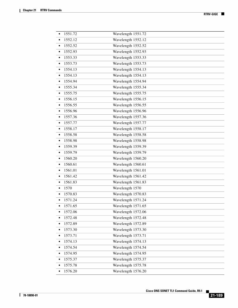
Chapter 21 RTRV CommandsRTRV-GIGE
• 1551.72 Wavelength 1551.72
• 1552.12 Wavelength 1552.12
• 1552.52 Wavelength 1552.52
• 1552.93 Wavelength 1552.93
• 1553.33 Wavelength 1553.33
• 1553.73 Wavelength 1553.73
• 1554.13 Wavelength 1554.13
• 1554.13 Wavelength 1554.13
• 1554.94 Wavelength 1554.94
• 1555.34 Wavelength 1555.34
• 1555.75 Wavelength 1555.75
• 1556.15 Wavelength 1556.15
• 1556.55 Wavelength 1556.55
• 1556.96 Wavelength 1556.96
• 1557.36 Wavelength 1557.36
• 1557.77 Wavelength 1557.77
• 1558.17 Wavelength 1558.17
• 1558.58 Wavelength 1558.58
• 1558.98 Wavelength 1558.98
• 1559.39 Wavelength 1559.39
• 1559.79 Wavelength 1559.79
• 1560.20 Wavelength 1560.20
• 1560.61 Wavelength 1560.61
• 1561.01 Wavelength 1561.01
• 1561.42 Wavelength 1561.42
• 1561.83 Wavelength 1561.83
• 1570 Wavelength 1570
• 1570.83 Wavelength 1570.83
• 1571.24 Wavelength 1571.24
• 1571.65 Wavelength 1571.65
• 1572.06 Wavelength 1572.06
• 1572.48 Wavelength 1572.48
• 1572.89 Wavelength 1572.89
• 1573.30 Wavelength 1573.30
• 1573.71 Wavelength 1573.71
• 1574.13 Wavelength 1574.13
• 1574.54 Wavelength 1574.54
• 1574.95 Wavelength 1574.95
• 1575.37 Wavelength 1575.37
• 1575.78 Wavelength 1575.78
• 1576.20 Wavelength 1576.20
21-189Cisco ONS SONET TL1 Command Guide, R9.1
78-18890-01

Chapter 21 RTRV CommandsRTRV-GIGE
• 1576.61 Wavelength 1576.61
• 1577.03 Wavelength 1577.03
• 1577.44 Wavelength 1577.44
• 1577.86 Wavelength 1577.86
• 1578.27 Wavelength 1578.27
• 1578.69 Wavelength 1578.69
• 1579.10 Wavelength 1579.10
• 1579.52 Wavelength 1579.52
• 1579.93 Wavelength 1579.93
• 1580.35 Wavelength 1580.35
• 1580.77 Wavelength 1580.77
• 1581.18 Wavelength 1581.18
• 1581.60 Wavelength 1581.60
• 1582.02 Wavelength 1582.02
• 1582.44 Wavelength 1582.44
• 1582.85 Wavelength 1582.85
• 1583.27 Wavelength 1583.27
• 1583.69 Wavelength 1583.69
• 1584.11 Wavelength 1584.11
• 1584.53 Wavelength 1584.53
• 1584.95 Wavelength 1584.95
• 1585.36 Wavelength 1585.36
• 1585.78 Wavelength 1585.78
• 1586.20 Wavelength 1586.20
• 1586.62 Wavelength 1586.62
• 1587.04 Wavelength 1587.04
• 1587.46 Wavelength 1587.46
• 1587.88 Wavelength 1587.88
• 1588.30 Wavelength 1588.30
• 1588.73 Wavelength 1588.73
• 1589.15 Wavelength 1589.15
• 1589.57 Wavelength 1589.57
• 1589.99 Wavelength 1589.99
• 1590 Wavelength 1590
• 1590.41 Wavelength 1590.41
• 1590.83 Wavelength 1590.83
• 1591.26 Wavelength 1591.26
• 1591.68 Wavelength 1591.68
• 1592.10 Wavelength 1592.10
• 1592.52 Wavelength 1592.52
• 1592.95 Wavelength 1592.95
21-190Cisco ONS SONET TL1 Command Guide, R9.1
78-18890-01
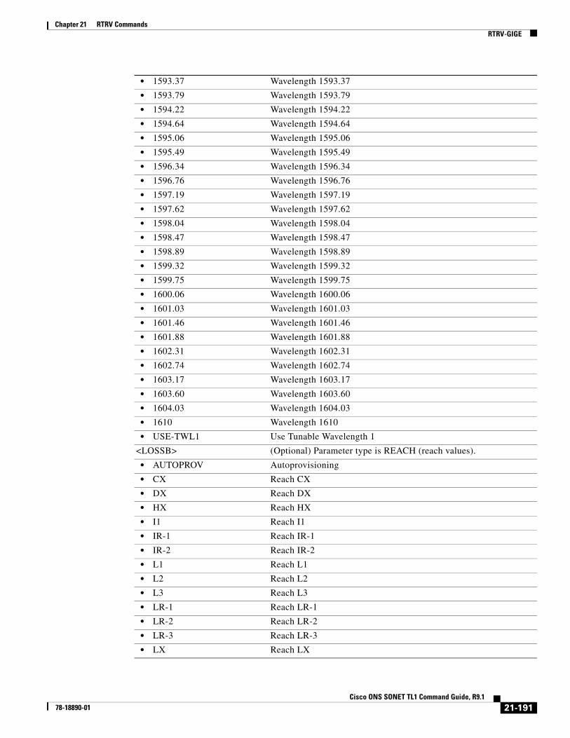
Chapter 21 RTRV CommandsRTRV-GIGE
• 1593.37 Wavelength 1593.37
• 1593.79 Wavelength 1593.79
• 1594.22 Wavelength 1594.22
• 1594.64 Wavelength 1594.64
• 1595.06 Wavelength 1595.06
• 1595.49 Wavelength 1595.49
• 1596.34 Wavelength 1596.34
• 1596.76 Wavelength 1596.76
• 1597.19 Wavelength 1597.19
• 1597.62 Wavelength 1597.62
• 1598.04 Wavelength 1598.04
• 1598.47 Wavelength 1598.47
• 1598.89 Wavelength 1598.89
• 1599.32 Wavelength 1599.32
• 1599.75 Wavelength 1599.75
• 1600.06 Wavelength 1600.06
• 1601.03 Wavelength 1601.03
• 1601.46 Wavelength 1601.46
• 1601.88 Wavelength 1601.88
• 1602.31 Wavelength 1602.31
• 1602.74 Wavelength 1602.74
• 1603.17 Wavelength 1603.17
• 1603.60 Wavelength 1603.60
• 1604.03 Wavelength 1604.03
• 1610 Wavelength 1610
• USE-TWL1 Use Tunable Wavelength 1
<LOSSB> (Optional) Parameter type is REACH (reach values).
• AUTOPROV Autoprovisioning
• CX Reach CX
• DX Reach DX
• HX Reach HX
• I1 Reach I1
• IR-1 Reach IR-1
• IR-2 Reach IR-2
• L1 Reach L1
• L2 Reach L2
• L3 Reach L3
• LR-1 Reach LR-1
• LR-2 Reach LR-2
• LR-3 Reach LR-3
• LX Reach LX
21-191Cisco ONS SONET TL1 Command Guide, R9.1
78-18890-01

Chapter 21 RTRV CommandsRTRV-GIGE
• S1 Reach S1
• S2 Reach S2
• SR Reach SR
• SR-1 Reach SR-1
• SX Reach SX
• T Reach T
• VX Reach VX
• ZX Reach ZX
<SOAK> (Optional) IS-AINS to IS transition soak time as measured in 15-minute intervals. SOAK is an integer.
<SOAKLEFT> (Optional) OOS-AINS to IS transition soak time as measured in one minute intervals. The format is HH-MM, where HH ranges from 00 to 48, and MM ranges from 00 to 59. The rules for SOAKLEFT are as follows:
• When the port is in OOS, OOS-MT to IS state, the parameter will not be displayed.
• When the port is in IS-AINS state, but the countdown has not stated due to faulty signal, the value will be SOAKLEFT=\"NOT-STARTED\".
• When the port is in IS-AINS state and the countdown has started, the value will be shown in HH-MM format.
<LIENABLE> (Optional) Enable or Disable link integrity timer. Takes either Y or N. Value Y enables the LITIMER and value N disables LITIMER.
By default LITIMER is enabled.
Note The LIENABLE parameter is supported on only CE-1000-4 and CE-1000T-8 cards on the 15454; the LIENABLE parameter is supported on only the CE-1000T-8 card on the 15310-MA.
<LITIMER> (Optional) Link integrity timer duration in the range between 200 ms and 10000 ms in multiples on 100 ms.
Note The LITIMER parameter is supported on only CE-1000-4 and CE-1000T-8 cards on the 15454; the LITIMER parameter is supported on only the CE-1000T-8 card on the 15310-MA.
<PST> Primary state. The parameter type is PST, which indicates the current overall service condition of an entity.
• IS In Service
• OOS Out of Service
<SST> Secondary state of the entity. The parameter type is SST, which provides additional information pertaining to PST and PSTQ.
• AINS Automatic In-Service
• DSBLD Disabled
• LPBK Loopback
• MEA Mismatch of Equipment
• MT Maintenance
21-192Cisco ONS SONET TL1 Command Guide, R9.1
78-18890-01

Chapter 21 RTRV CommandsRTRV-HDLC
21.56 RTRV-HDLC(Cisco ONS 15454 and ONS 15600) The Retrieve High-Level Data Link Control (RTRV-HDLC) command retrieves HDLC-related attributes.
Usage Guidelines None
Category Ports
Security Retrieve
Input Format RTRV-HDLC:[<TID>]:<AID>:<CTAG>;
Input Example RTRV-HDLC:TID:VFAC-SLOT-PORT:CTAG;
Input Parameters
Output Format SID DATE TIMEM CTAG COMPLD “<AID>::[FCS=<FCS>]”;
Output Example TID-000 1998-06-20 14:30:00M 001 COMPLD “VFAC-SLOT-PORT::FCS=FCS-16”;
Output Parameters
• OOG Out of Group
• SWDL Software Download
• UAS Unassigned
• UEQ Unequipped
<AID> Access identifier from the “26.15 FACILITY” section on page 35. The ONS 15600 ASAP card uses the VFAC AID.
<AID> Access identifier from the “26.15 FACILITY” section on page 35. The ONS 15600 ASAP card uses the VFAC AID.
<FCS> (Optional) Payload frame check sequence. The parameter type is FCS, which is the frame check sequence.
21-193Cisco ONS SONET TL1 Command Guide, R9.1
78-18890-01

Chapter 21 RTRV CommandsRTRV-HDR
21.57 RTRV-HDR(Cisco ONS 15454, 15327, 15600, 15310) The Retrieve Header (RTRV-HDR) command retrieves the header of a TL1 response message. It is used by TL1 clients to determine if the link to the NE is still active and if the NE is responding to commands.
Usage Guidelines None
Category System
Security Retrieve
Input Format RTRV-HDR:[<TID>]::<CTAG>;
Input Example RTRV-HDR:SONOMA::232;
Input Parameters None that require description
21.58 RTRV-INV(Cisco ONS 15454, 15327, 15600, 15310) The Retrieve Inventory (RTRV-INV) command retrieves a list of the equipment inventory. For each unit in the system, the list identifies the unit's firmware numbers and Common Language Equipment Identifier (CLEI) codes, and the system’s product ID and version ID. This command also retrieves the inventory information from pluggable modules using the AID PPM-SLOT-PORT format. For multishelf nodes, the inventory parameters are retrieved by using RTRV-INV command with the BP AID. Because there is more that one shelf, the SHELFID is specified in the BP AID.
Usage Guidelines None
Category System
• FCS-16 Frame check sequencing using 16 bits
• FCS-32 Frame check sequencing using 32 bits
• NONE No frame check sequence
21-194Cisco ONS SONET TL1 Command Guide, R9.1
78-18890-01

Chapter 21 RTRV CommandsRTRV-INV
Security Retrieve
Input Format RTRV-INV:[<TID>]:<AID>:<CTAG>[::::];
Input Example RTRV-INV:OCCIDENTAL:SLOT-15:301;
Input Parameters
Output Format SID DATE TIMEM CTAG COMPLD "<AID>,<AIDTYPE>::[PLUGTYPE=<PLUGTYPE>],[PN=<PN>],[HWREV=<HWREV>], [FWREV=<FWREV>],[SN=<SN>],[CLEI=<CLEI>],[TWL=<TWL>],[PLUGINVENDORID=<PLUGINVENDORID>],[PLUGINPN=<PLUGINPN>],[PLUGINHWREV=<PLUGINWREV>], [PLUGINFWREV=<PLUGINFWREV>],[PLUGINSN=<PLUGINSN>],[ILOSSREF=<ILOSSREF>],[PID=<PID>],[VID=<VID>],[FPGA=<FPGA>],[MODULETYPE=<MODULETYPE>]";
Output Example TID-000 1998-06-20 14:30:00M 001 COMPLD “SLOT-15,OC3-IR-4::PLUGTYPE=SX-IR-SW-SN,PN=87-31-00002,HWREV=004K, FWREV=76-99-00009-004A,SN=013510,CLEI=NOCLEI,TWL1=1546.12,TWL2=1546.92, TWL3=1547.72,TWL4=1548.51,PLUGINVENDORID=012345,PLUGINPN=ABCDE, PLUGINHWREV=ABCDE,PLUGINFWREV=01-02-03,PLUGINSN=01234,ILOSSREF=1.0, PID=CISCO_ONS15454,VID=V01,FPGA=F451,MODULETYPE=101”;
Output Parameters
<AID> Access identifier from the “26.14 EQPT” section on page 33 or ALL.
<AID> Access identifier from the “26.14 EQPT” section on page 33
<AIDTYPE> Specifies the type of (AID) facility, link or other addressable entity targeted by the message. AIDTYPE is a string.
<PLUGTYPE> (Optional) Describes the type of plug-in. PLUGTYPE is a string.
<PN> (Optional) Hardware part number. PN is a string.
<HWREV> (Optional) Hardware revision. HWREV is a string.
<FWREV> (Optional) Firmware revision. It is also known as Bootrom revision. FWREV is a string.
<SN> (Optional) Serial number. SN is a string.
<CLEI> (Optional) Common language equipment identifier code for the equipment. CLEI is a string.
<TWL1> (Optional) Tunable wavelength 1.
• 1310 Wavelength 1310
21-195Cisco ONS SONET TL1 Command Guide, R9.1
78-18890-01
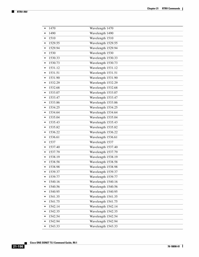
Chapter 21 RTRV CommandsRTRV-INV
• 1470 Wavelength 1470
• 1490 Wavelength 1490
• 1510 Wavelength 1510
• 1529.55 Wavelength 1529.55
• 1529.94 Wavelength 1529.94
• 1530 Wavelength 1530
• 1530.33 Wavelength 1530.33
• 1530.73 Wavelength 1530.73
• 1531.12 Wavelength 1531.12
• 1531.51 Wavelength 1531.51
• 1531.90 Wavelength 1531.90
• 1532.29 Wavelength 1532.29
• 1532.68 Wavelength 1532.68
• 1533.07 Wavelength 1533.07
• 1533.47 Wavelength 1533.47
• 1533.86 Wavelength 1533.86
• 1534.25 Wavelength 1534.25
• 1534.64 Wavelength 1534.64
• 1535.04 Wavelength 1535.04
• 1535.43 Wavelength 1535.43
• 1535.82 Wavelength 1535.82
• 1536.22 Wavelength 1536.22
• 1536.61 Wavelength 1536.61
• 1537 Wavelength 1537
• 1537.40 Wavelength 1537.40
• 1537.79 Wavelength 1537.79
• 1538.19 Wavelength 1538.19
• 1538.58 Wavelength 1538.58
• 1538.98 Wavelength 1538.98
• 1539.37 Wavelength 1539.37
• 1539.77 Wavelength 1539.77
• 1540.16 Wavelength 1540.16
• 1540.56 Wavelength 1540.56
• 1540.95 Wavelength 1540.95
• 1541.35 Wavelength 1541.35
• 1541.75 Wavelength 1541.75
• 1542.14 Wavelength 1542.14
• 1542.35 Wavelength 1542.35
• 1542.54 Wavelength 1542.54
• 1542.94 Wavelength 1542.94
• 1543.33 Wavelength 1543.33
21-196Cisco ONS SONET TL1 Command Guide, R9.1
78-18890-01

Chapter 21 RTRV CommandsRTRV-INV
• 1543.73 Wavelength 1543.73
• 1544.13 Wavelength 1544.13
• 1544.53 Wavelength 1544.53
• 1544.92 Wavelength 1544.92
• 1545.32 Wavelength 1545.32
• 1545.72 Wavelength 1545.72
• 1546.12 Wavelength 1546.12
• 1546.52 Wavelength 1546.52
• 1546.92 Wavelength 1546.92
• 1547.32 Wavelength 1547.32
• 1547.72 Wavelength 1547.72
• 1548.12 Wavelength 1548.12
• 1548.51 Wavelength 1548.51
• 1548.92 Wavelength 1548.92
• 1549.32 Wavelength 1549.32
• 1549.71 Wavelength 1549.71
• 1550 Wavelength 1500
• 1550.12 Wavelength 1550.12
• 1550.52 Wavelength 1550.52
• 1550.92 Wavelength 1550.92
• 1551.32 Wavelength 1551.32
• 1551.72 Wavelength 1551.72
• 1552.12 Wavelength 1552.12
• 1552.52 Wavelength 1552.52
• 1552.93 Wavelength 1552.93
• 1553.33 Wavelength 1553.33
• 1553.73 Wavelength 1553.73
• 1554.13 Wavelength 1554.13
• 1554.13 Wavelength 1554.13
• 1554.94 Wavelength 1554.94
• 1555.34 Wavelength 1555.34
• 1555.75 Wavelength 1555.75
• 1556.15 Wavelength 1556.15
• 1556.55 Wavelength 1556.55
• 1556.96 Wavelength 1556.96
• 1557.36 Wavelength 1557.36
• 1557.77 Wavelength 1557.77
• 1558.17 Wavelength 1558.17
• 1558.58 Wavelength 1558.58
• 1558.98 Wavelength 1558.98
• 1559.39 Wavelength 1559.39
21-197Cisco ONS SONET TL1 Command Guide, R9.1
78-18890-01
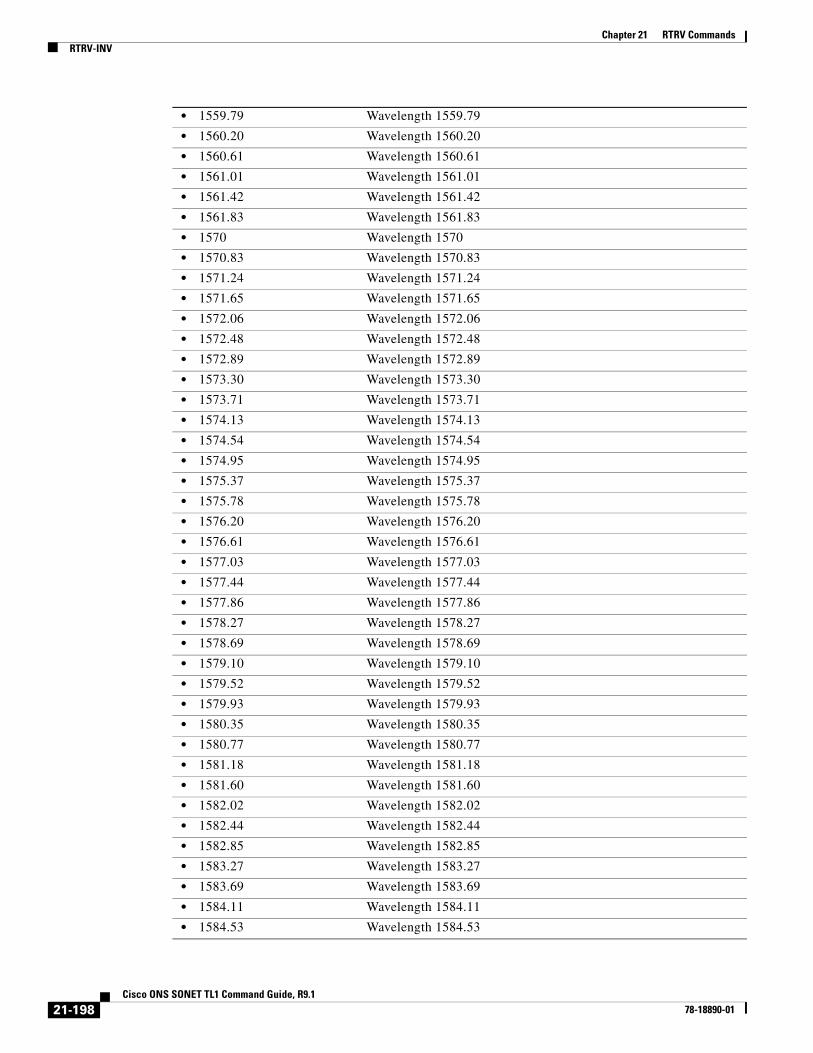
Chapter 21 RTRV CommandsRTRV-INV
• 1559.79 Wavelength 1559.79
• 1560.20 Wavelength 1560.20
• 1560.61 Wavelength 1560.61
• 1561.01 Wavelength 1561.01
• 1561.42 Wavelength 1561.42
• 1561.83 Wavelength 1561.83
• 1570 Wavelength 1570
• 1570.83 Wavelength 1570.83
• 1571.24 Wavelength 1571.24
• 1571.65 Wavelength 1571.65
• 1572.06 Wavelength 1572.06
• 1572.48 Wavelength 1572.48
• 1572.89 Wavelength 1572.89
• 1573.30 Wavelength 1573.30
• 1573.71 Wavelength 1573.71
• 1574.13 Wavelength 1574.13
• 1574.54 Wavelength 1574.54
• 1574.95 Wavelength 1574.95
• 1575.37 Wavelength 1575.37
• 1575.78 Wavelength 1575.78
• 1576.20 Wavelength 1576.20
• 1576.61 Wavelength 1576.61
• 1577.03 Wavelength 1577.03
• 1577.44 Wavelength 1577.44
• 1577.86 Wavelength 1577.86
• 1578.27 Wavelength 1578.27
• 1578.69 Wavelength 1578.69
• 1579.10 Wavelength 1579.10
• 1579.52 Wavelength 1579.52
• 1579.93 Wavelength 1579.93
• 1580.35 Wavelength 1580.35
• 1580.77 Wavelength 1580.77
• 1581.18 Wavelength 1581.18
• 1581.60 Wavelength 1581.60
• 1582.02 Wavelength 1582.02
• 1582.44 Wavelength 1582.44
• 1582.85 Wavelength 1582.85
• 1583.27 Wavelength 1583.27
• 1583.69 Wavelength 1583.69
• 1584.11 Wavelength 1584.11
• 1584.53 Wavelength 1584.53
21-198Cisco ONS SONET TL1 Command Guide, R9.1
78-18890-01

Chapter 21 RTRV CommandsRTRV-INV
• 1584.95 Wavelength 1584.95
• 1585.36 Wavelength 1585.36
• 1585.78 Wavelength 1585.78
• 1586.20 Wavelength 1586.20
• 1586.62 Wavelength 1586.62
• 1587.04 Wavelength 1587.04
• 1587.46 Wavelength 1587.46
• 1587.88 Wavelength 1587.88
• 1588.30 Wavelength 1588.30
• 1588.73 Wavelength 1588.73
• 1589.15 Wavelength 1589.15
• 1589.57 Wavelength 1589.57
• 1589.99 Wavelength 1589.99
• 1590 Wavelength 1590
• 1590.41 Wavelength 1590.41
• 1590.83 Wavelength 1590.83
• 1591.26 Wavelength 1591.26
• 1591.68 Wavelength 1591.68
• 1592.10 Wavelength 1592.10
• 1592.52 Wavelength 1592.52
• 1592.95 Wavelength 1592.95
• 1593.37 Wavelength 1593.37
• 1593.79 Wavelength 1593.79
• 1594.22 Wavelength 1594.22
• 1594.64 Wavelength 1594.64
• 1595.06 Wavelength 1595.06
• 1595.49 Wavelength 1595.49
• 1596.34 Wavelength 1596.34
• 1596.76 Wavelength 1596.76
• 1597.19 Wavelength 1597.19
• 1597.62 Wavelength 1597.62
• 1598.04 Wavelength 1598.04
• 1598.47 Wavelength 1598.47
• 1598.89 Wavelength 1598.89
• 1599.32 Wavelength 1599.32
• 1599.75 Wavelength 1599.75
• 1600.06 Wavelength 1600.06
• 1601.03 Wavelength 1601.03
• 1601.46 Wavelength 1601.46
• 1601.88 Wavelength 1601.88
• 1602.31 Wavelength 1602.31
21-199Cisco ONS SONET TL1 Command Guide, R9.1
78-18890-01

Chapter 21 RTRV CommandsRTRV-L2-ETH
Note If the SFP contains manufacturing information or data that is not compliant with Telcordia GR-831 (Appendix A), the system automatically adds quotes (\"\") around the invalid characters in the TL1 response. TL1 is Telcordia GR-831 compliant after Software Release 7.0.4.
21.59 RTRV-L2-ETH(Cisco ONS 15454) The Retrieve Layer 2 Ethernet (RTRV-L2-ETH) command retrieves the Layer 2 port information of the Ethernet card.
Usage Guidelines None
• 1602.74 Wavelength 1602.74
• 1603.17 Wavelength 1603.17
• 1603.60 Wavelength 1603.60
• 1604.03 Wavelength 1604.03
• 1610 Wavelength 1610
• USE-TWL1 Use Tunable Wavelength 1
<PLUGINVENDORID> (Optional) Plugin vendor ID. Integer.
<PLUGINPN> (Optional) Third-party plug-in module HW part number. Applicable only to optical service channel cards, optical amplifier cards, dispersion compensation units, multiplexer and demultiplexer cards, and OADM cards. PLUGINPN is a string.
<PLUGINHWREV> (Optional) Third-party plug-in module hardware revision. Applicable only to optical service channel cards, optical amplifier cards, dispersion compensation units, multiplexer and demultiplexer cards, and OADM cards. PLUGINHWREV is a string.
<PLUGINFWREV> (Optional) Third-party plug-in module firmware. Applicable only to optical service channel cards, optical amplifier cards, dispersion compensation units, multiplexer and demultiplexer cards, and OADM cards. PLUGINFWREV is a string.
<PLUGINSN> (Optional) Third-party plug-in module serial number. Applicable only to optical service channel cards, optical amplifier cards, dispersion compensation units, multiplexer and demultiplexer cards, and OADM cards. PLUGINSW is a string.
<ILOSSREF> (Optional) The insertion loss reference calculated by the unit as worst insertion loss of all the unit. The parameter type is REVERTIVE_TIME.
• 0.5 to 12.0 Revertive time is 0.5 to 12.0 minutes
<PID> (Optional) Product ID of the module. PID is a string.
<VID> (Optional) Vendor ID. VID is a string.
<FPGA> (Optional) FPGA version. FPGA is a string.
<MODULETYPE> (Optional) Describes the type of embedded plugin module. String.
21-200Cisco ONS SONET TL1 Command Guide, R9.1
78-18890-01

Chapter 21 RTRV CommandsRTRV-L2-ETH
Category Ethernet
Security Retrieve
Input Format RTRV-L2-ETH:[<TID>]:<AID>:<CTAG>[:::];
Input Example RTRV-L2-ETH:PETALUMA:FAC-1-1:CTAG;
Input Parameters
Output Format SID DATE TIMEM CTAG COMPLD"<AID>::[NIMODE=<TYPE>],[MACLEARNING=<MACLEARNING>],[INGRESSCOS=<INGRESSCOS>],[ETHERCETYPE=<ETHERCETYPE>],[ETHERSTYPE=<ETHERSTYPE>],[ALWMACADDR=<ALWMACADDR>],[INHMACADDR=<INHMACADDR>],[BPDU=<BPDU>],[ACTBRIDGESTATE=<ACTBRIDGESTATE>],[BRIDGESTATE=<BRIDGESTATE>],[QNQMODE=<QNQMODE>],[TRNSPSVLAN=<TRNSPSVLAN>],[NAME=<NAME>]:[<PST>[,<SST>]]
;
Output Example TID-000 1998-06-20 14:30:00M 001 COMPLD "ETH-1-1-1::NIMODE=NNI,MACLEARNING=Y,INGRESSCOS=8,ETHERCETYPE=8100,ETHERSTYPE=8100,ALWMACADDR=aa-bb-cc-dd-ee-ff&zz-yy-ww-tt-ss-rr,,BPDU=Y,BRIDGESTATE=DISABLED,,QNQMODE=TRANSPARENT,TRNSPSVLAN=4096,NAME="Ethernet":OOS-AU,AINS";
Output Parameters
<AID> Ethernet AIDs are used to access L2 Ethernet ports. Access identifier from the “26.15 FACILITY” section on page 35.
<ETHERNET> Ethernet AIDs are used to access L2 Ethernet ports. Access identifier from the “26.15 FACILITY” section on page 35.
<NIMODE> Identifies the Ethernet network interface mode.
• NNI (Default) Network-network interface mode
• UNI User-network interface mode
<MACLEARNING> MAC address learning mode. This activates MAC address learning on the interface to avoid packet broadcasting.
• Y Enables MAC learning
• N Disable MAC learning
21-201Cisco ONS SONET TL1 Command Guide, R9.1
78-18890-01
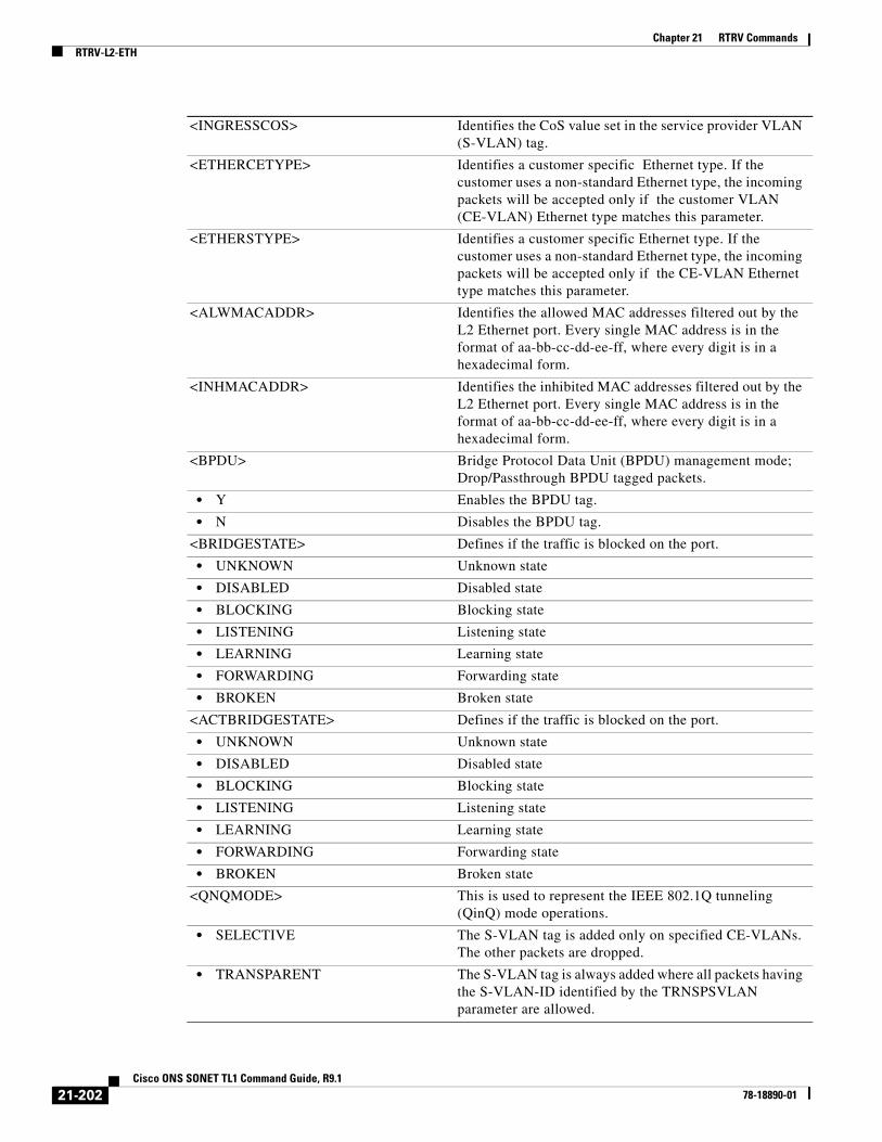
Chapter 21 RTRV CommandsRTRV-L2-ETH
<INGRESSCOS> Identifies the CoS value set in the service provider VLAN (S-VLAN) tag.
<ETHERCETYPE> Identifies a customer specific Ethernet type. If the customer uses a non-standard Ethernet type, the incoming packets will be accepted only if the customer VLAN (CE-VLAN) Ethernet type matches this parameter.
<ETHERSTYPE> Identifies a customer specific Ethernet type. If the customer uses a non-standard Ethernet type, the incoming packets will be accepted only if the CE-VLAN Ethernet type matches this parameter.
<ALWMACADDR> Identifies the allowed MAC addresses filtered out by the L2 Ethernet port. Every single MAC address is in the format of aa-bb-cc-dd-ee-ff, where every digit is in a hexadecimal form.
<INHMACADDR> Identifies the inhibited MAC addresses filtered out by the L2 Ethernet port. Every single MAC address is in the format of aa-bb-cc-dd-ee-ff, where every digit is in a hexadecimal form.
<BPDU> Bridge Protocol Data Unit (BPDU) management mode; Drop/Passthrough BPDU tagged packets.
• Y Enables the BPDU tag.
• N Disables the BPDU tag.
<BRIDGESTATE> Defines if the traffic is blocked on the port.
• UNKNOWN Unknown state
• DISABLED Disabled state
• BLOCKING Blocking state
• LISTENING Listening state
• LEARNING Learning state
• FORWARDING Forwarding state
• BROKEN Broken state
<ACTBRIDGESTATE> Defines if the traffic is blocked on the port.
• UNKNOWN Unknown state
• DISABLED Disabled state
• BLOCKING Blocking state
• LISTENING Listening state
• LEARNING Learning state
• FORWARDING Forwarding state
• BROKEN Broken state
<QNQMODE> This is used to represent the IEEE 802.1Q tunneling (QinQ) mode operations.
• SELECTIVE The S-VLAN tag is added only on specified CE-VLANs. The other packets are dropped.
• TRANSPARENT The S-VLAN tag is always added where all packets having the S-VLAN-ID identified by the TRNSPSVLAN parameter are allowed.
21-202Cisco ONS SONET TL1 Command Guide, R9.1
78-18890-01

Chapter 21 RTRV CommandsRTRV-LMP
21.60 RTRV-LMP(Cisco ONS 15454, 15327, 15600, 15310) The Retrieve Link Management Protocol (RTRV-LMP) command retrieves the global LMP protocol attributes.
Usage Guidelines This command is only available on platforms that support the LMP protocol.
Category LMP
Security Provisioning
<TRNSPSVLAN> VLAN identifier. A VLAN ID is a number between 1 and 4096. The value 0 is reserved for untagged VLANs. This identifier is used for customer VLAN IDs and service provider VLAN IDs.
<NAME> (Optional) Facility name. NAME is a string.
<CMDMDE> The parameter type is command mode (CMDMDE). Normal (NORM) mode is the default behavior for all commands but you can specify forced (FRCD) mode to force the system to override a state where the command would normally be denied. The FRCD mode of operation is applicable to delete a virtual concatenated (VCAT) member cross-connect in IS-NR or OOS-AU,AINS service states.
<PST> Primary state. The parameter type is PST, which indicates the current overall service condition of an entity.
• IS In service
• OOS Out of service
<SST> Secondary state. The parameter type is SST, which provides additional information pertaining to PST and PSTQ.
• AINS Automatic in service
• DSBLD Disabled
• LPBK Loopback
• MEA Mismatch of equipment and attributes
• MT Maintenance mode
• OOG Out of group
• SWDL Software downloading
• UAS Unassigned
• UEQ Unequipped
21-203Cisco ONS SONET TL1 Command Guide, R9.1
78-18890-01

Chapter 21 RTRV CommandsRTRV-LMP-CTRL
Input Format RTRV-LMP:[<TID>]::<CTAG>;
Input Example RTRV-LMP:PETALUMA::704;
Input Parameters None.
Output Format SID DATE TIME
M CTAG COMPLD "::ENABLE=<ENABLE>,[WDM=<WDM>],[ROLE=<ROLE>],[NODEID=<NODEID>],[OPSTATE=<OPSTATE>]";
Output Example TID-000 1998-06-20 14:30:00M 001 COMPLD "::ENABLE=Y,WDM=Y,ROLE=PEER,NODEID=198.133.219.25,OPSTATE=UP"
;
Output Parameters
21.61 RTRV-LMP-CTRL(Cisco ONS 15454, 15327, 15600, 15310) The Retrieve Link Management Protocol Control Channel (RTRV-LMP-CTRL) command retrieves the attributes of an LMP control channel.
<ENABLE> LMP protocol status
• Y Protocol is enabled.
• N Protocol is disabled.
<WDM> Determines if the LMP WDM extensions are in effect.
• Y The LMP WDM extensions are in effect.
• N The LMP WDM extensions are not in effect.
<ROLE> The role the LMP protocol is configured to play.
• OLS The LMP protocol is configured to respond as a Optical Line System.
• PEER The LMP protocol is configured to respond as a peer node.
<NODEID> LMP Node ID. NODEID is a stable IP address that is always reachable if there is any connectivity to it. The default LMP node ID value is the IP address of the node.
<OPSTATE> Indicates the operational status of the LMP protocol stack.
• UP LMP protocol is active.
• DOWN LMP protocol is not active.
21-204Cisco ONS SONET TL1 Command Guide, R9.1
78-18890-01

Chapter 21 RTRV CommandsRTRV-LMP-CTRL
Usage Guidelines This command is only available on platforms that support the LMP protocol.
Category LMP
Security Provisioning
Input Format RTRV-LMP-CTRL:[<TID>]:<SRC>:<CTAG>;
Input Example RTRV-LMP-CTRL:PETALUMA:CC-123:704;
Input Parameters
Output Format SID DATE TIMEM CTAG COMPLD"<AID>::REMOTEID=<REMOTEID>,LOCALPORT=<LOCALPORT>,REMOTEIP=<REMOTEIP>,[HELLO=<HELLO>],[HELLOMIN=<HELLOMIN>],[HELLOMAX=<HELLOMAX>],[DEAD=<DEAD>],[DEADMIN=<DEADMIN>],[DEADMAX=<DEADMAX>],[OPSTATE=<OPSTATE>]:[<PST>[,<SST>]];
Output Example TID-000 1998-06-20 14:30:0M 001 COMPLD "CTRL-2::REMOTEID=15.15.15.115,LOCALPORT=FAC-1-1-1,REMOTEIP=126.0.0.1,HELLO=50,HELLOMIN=300,HELLOMAX=5000,DEAD=12000,DEADMIN=2000,DEADMAX=20000,OPSTATE=UP:OOS,DSBLD";
Output Parameters
<SRC> The LMP control channel AID.
• CTRL-ALL Specifies all the control channels.
• CTRL-{1-4} Specifies an individual control channel.
<REMOTEID> Distinguishes the LMP control channel messages that are using the same local port to send messages.
<LOCALPORT> The pathway that the LMP control channel will use to send and receive messages.
<REMOTEIP> Remote IP address with which the LMP control channel sends and receives messages.
<HELLO> The time interval within which the LMP protocol sends HELLO messages.
<HELLOMIN> Minimum hello time the LMP control channels can send out HELLO messages to the remote node.
21-205Cisco ONS SONET TL1 Command Guide, R9.1
78-18890-01

Chapter 21 RTRV CommandsRTRV-LMP-CTRL
<HELLOMAX> The maximum amount of time the LMP control channel can wait between HELLO messages.
<DEAD> Time interval an LMP control channel will wait for a HELLO message from the remote side before listing the control channel as down.
<DEADMIN> The minimum amount of time that an LMP control channel can wait before listing the control channel status as down.
<DEADMAX> The maximum amount of time that an LMP control channel can wait before listing the control channel status as down.
<OPSTATE> Indicates the operational status of the LMP protocol stack.
• UP The control channel is communicating with its counterpart on the remote node.
• DOWN The control channel is not communicating with its counterpart on the remote node.
• GOING DOWN The LMP stack sets the ControlChannelDown bit in all the messages it sends. This is mainly because of administrative action.
• GOING UP The control channel is in the process of transitioning to the UP state.
• CFG-SND The control channel is in the parameter negotiation state. In this state, the node periodically sends a Config message, and is expecting the other side to reply with either a ConfigAck or ConfigNack message. The control channel Finite State Machine (FSM) does not transition into the ACTIVE state until the remote side positively acknowledges the parameters.
• CFG-RCV The control channel is in the parameter negotiation state. In this state, the node is waiting for acceptable configuration parameters from the remote side. After these parameters are received and acknowledged, the FSM can transition to the ACTIVE state response.
• ACTIVE In this state, the node periodically sends a Hello message and is waiting to receive a valid Hello message. After a valid Hello message is received, it can transition to the UP state.
• ACT-FAILED Activation of the control channel failed.
• UNKNOWN Unknown or unexpected state.
<PST> Primary state. The parameter type is PST, which indicates the current overall service condition of an entity.
• IS In Service
• OOS Out of Service
<SST> Secondary state of the entity. The parameter type is SST, which provides additional information pertaining to PST and PSTQ.
• AINS Automatic In-Service
• DSBLD Disabled
• LPBK Loopback
• MEA Mismatch of Equipment
• MT Maintenance
• OOG Out of Group
• SWDL Software Download
21-206Cisco ONS SONET TL1 Command Guide, R9.1
78-18890-01

Chapter 21 RTRV CommandsRTRV-LMP-TLINK
21.62 RTRV-LMP-TLINK(Cisco ONS 15454, 15327, 15600, 15310) The Retrieve Link Management Protocol (RTRV-LMP-TLINK) command retrieves the attributes of an LMP Traffic Engineering (TE) link.
Usage Guidelines This command is limited to nodes where the LMP protocol is supported and has been enabled.
Category LMP
Security Provisioning
Input Format RTRV-LMP-TLINK:[<TID>]:<SRC>:<CTAG>;
Input Example RTRV-LMP-TLINK:PETALUMA:TLINK-123:704;
Input Parameters
Output Format SID DATE TIMEM CTAG COMPLD "<SRC>::[REMOTEID=<REMOTEID>],[DWDM=<DWDM>],[REMOTETE=<REMOTETE>],[MUXCAP=<MUXCAP>],[OPSTATE=<OPSTATE>]:[<PST>[,<SST>]]";
Output Example TID-000 1998-06-20 14:30:0M CTAG COMPLD "TLINK-2::REMOTEID=15.15.15.115,DWDM=Y,REMOTETE=3,MUXCAP=LAMBDA,OPSTATE=UP:IS";
Output Parameters
• UAS Unassigned
• UEQ Unequipped
<SRC> LMP TE link AID values.
• TLINK-ALL Specifies all the TE links.
• TLINK-{1-256} Specifies an individual TE link.
<SRC> LMP TE link AID values.
• TLINK-ALL Specifies all the TE links.
• TLINK-{1-256} Specifies an individual TE link.
21-207Cisco ONS SONET TL1 Command Guide, R9.1
78-18890-01

Chapter 21 RTRV CommandsRTRV-LMP-TLINK
<REMOTEID> Remote node ID associated with the LMP TE link.
<DWDM> Indicates whether or not the LMP TE link supports DWDM.
• Y The LMP TE link supports DWDM.
• N The LMP TE link does not support DWDM.
<REMOTETE> Remote ID used by the far-end LMP TE link.
<MUXCAP> The muxponder capability of the LMP TE link.
• PKTSWITCH1 Packet Switching 1
• PKTSWITCH2 Packet Switching 2
• PKTSWITCH3 Packet Switching 3
• PKTSWITCH4 Packet Switching 4
• LAYER2 Layer 2 switching
• TDM Time-division multiplexing (TDM) switching
• LAMBDA Lambda switching
• FIBER Fiber switching
<OPSTATE> Indicates the operational status of a TE link.
• DEGRADED In this state, all LMP control channels are down, but the TE link still includes some data links that are allocated to user traffic.
• INIT Data links have been allocated to the TE link, but the configuration has not yet been synchronized with the LMP neighbor. A LinkSummary message is periodically transmitted to the LMP neighbor.
• UP The TE link is communicating with its counterpart on the remote node.
• DOWN The TE link is not communicating with its counterpart on the remote node.
• UNKNOWN Unknown or unexpected state.
<PST> Primary state. This parameter indicates the current overall service condition of an entity.
• IS In service
• OOS Out of service
<SST> Secondary state. This parameter provides additional information pertaining to PST and PSTQ.
• AINS Automatic In-Service
• DSBLD Disabled
• LPBK Loopback
• MEA Mismatch of Equipment
• MT Maintenance
• OOG Out of Group
• SWDL Software Download
• UAS Unassigned
• UEQ Unequipped
21-208Cisco ONS SONET TL1 Command Guide, R9.1
78-18890-01

Chapter 21 RTRV CommandsRTRV-LMP-DLINK
21.63 RTRV-LMP-DLINK(Cisco ONS 15454, 15327, 15600, 15310) The Retrieve Link Management Protocol (RTRV-LMP-DLINK) command retrieves the attributes of an LMP data link.
Usage Guidelines This command is only applicable on a node where the LMP protocol is supported and enabled.
Category LMP
Security Provisioning
Input Format RTRVD-LMP-DLINK:[<TID>]:<SRC>:<CTAG>;
Input Example RTRV-LMP-DLINK:PETALUMA:FAC-14-1-1:704;
Input Parameters
Output Format SID DATE TIMEM CTAG COMPLD"<AID>::[LINKTYPE=<LINKTYPE>],[REMOTEID=<REMOTEID>],[TELINK=<TELINK>],[OPSTATE=<OPSTATE>]";
Output Example TID-000 1998-06-20 14:30:00M 001 COMPLD "FAC-14-1-1::LINKTYPE=PORT,REMOTEID=45,TELINK=TLINK-4,OPSTATE=UP-ALLOC"
;
Output Parameters
<SRC> Access identifier from the “26.15 FACILITY” section on page 35.
<SRC> Access identifier from the “26.15 FACILITY” section on page 35.
<LINKTYPE> The type of LMP data link.
• PORT Port data link.
• COMPONENT Component data link.
<REMOTEID> The remote LMP data link ID.
<TELINK> Used to map LMP data links to LMP TE links.
<OPSTATE> Indicates the operational status of an LMP data link.
• TESTING The data link is being tested. An LMP test message is periodically sent through the link.
21-209Cisco ONS SONET TL1 Command Guide, R9.1
78-18890-01
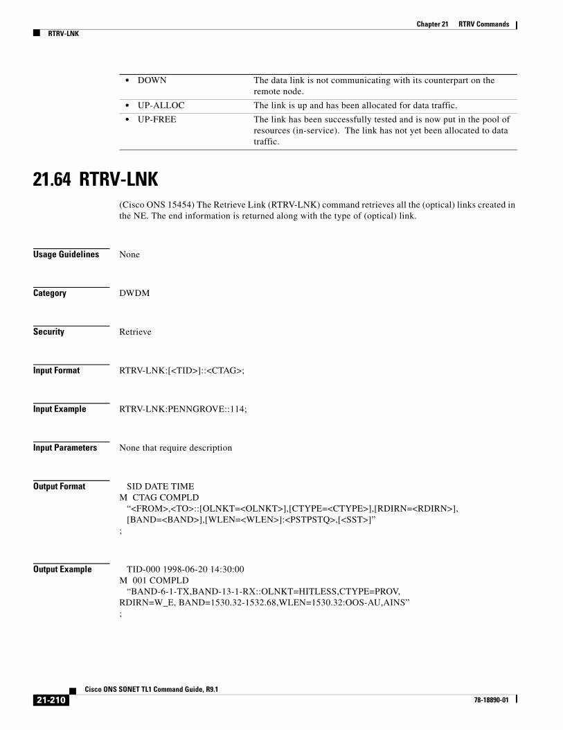
Chapter 21 RTRV CommandsRTRV-LNK
21.64 RTRV-LNK(Cisco ONS 15454) The Retrieve Link (RTRV-LNK) command retrieves all the (optical) links created in the NE. The end information is returned along with the type of (optical) link.
Usage Guidelines None
Category DWDM
Security Retrieve
Input Format RTRV-LNK:[<TID>]::<CTAG>;
Input Example RTRV-LNK:PENNGROVE::114;
Input Parameters None that require description
Output Format SID DATE TIMEM CTAG COMPLD “<FROM>,<TO>::[OLNKT=<OLNKT>],[CTYPE=<CTYPE>],[RDIRN=<RDIRN>], [BAND=<BAND>],[WLEN=<WLEN>]:<PSTPSTQ>,[<SST>]”;
Output Example TID-000 1998-06-20 14:30:00M 001 COMPLD “BAND-6-1-TX,BAND-13-1-RX::OLNKT=HITLESS,CTYPE=PROV,RDIRN=W_E, BAND=1530.32-1532.68,WLEN=1530.32:OOS-AU,AINS”;
• DOWN The data link is not communicating with its counterpart on the remote node.
• UP-ALLOC The link is up and has been allocated for data traffic.
• UP-FREE The link has been successfully tested and is now put in the pool of resources (in-service). The link has not yet been allocated to data traffic.
21-210Cisco ONS SONET TL1 Command Guide, R9.1
78-18890-01

Chapter 21 RTRV CommandsRTRV-LNK
Output Parameters <FROM> Access identifier from the “26.1 ALL” section on page 1. Identifies an entity at one end of the optical link.
<TO> Access identifier from the “26.1 ALL” section on page 1. Identifies an entity at the other end of the optical link.
<OLNKT> (Optional) Optical link type. The parameter type is OPTICAL_LINK_TYPE, which is the type of optical link between two optical facilities.
• ADD-DROP Link between two points that results in an add/drop connection from a drop point to an add point
• HITLESS Link between two OMS points that results in a hitless connection from a drop point to an add point of a consecutive band/channel filter
• MPO MPO connector
• OTS Link between two OTS points
• OTS-INTLEAV Link between two OTS points interrupted by an interleaver card that the system does not monitor.
<CTYPE> (Optional) The type of cross-connection. Indicates if the optical link is provisioned by the user or automatically created by the NE. The parameter type is CREATION_TYPE, which is the optical link creation type.
• AUTO Automatically created by the NE
• PROV Provisioned by the user
<RDIRN> (Optional) Ring directionality of the optical line. The parameter type is RDIRN_MODE, which is the optical ring directionality.
• E-W The direction of the signal is from east to west (clockwise).
• W-E The direction of the signal is from west to east (counterclockwise).
<BAND> (Optional) The optical band (group of four contiguous wavelengths) for this optical link. BAND is present only when there is a link between two OMS entities. The parameter type is OPTICAL_BAND.
• 1530.33 to 1532.68 Band 1
• 1534.25 to 1536.61 Band 2
• 1538.19 to 1540.56 Band 3
• 1542.14 to 1544.53 Band 4
• 1546.12 to 1548.51 Band 5
• 1550.12 to 1552.52 Band 6
• 1554.13 to 1556.55 Band 7
• 1558.17 to 1560.61 Band 8
• USE-DEFAULT This band is not yet configured/retrieved from the unit.
<WLEN> (Optional) Optical wavelength for this optical link. WLEN is present only when there is a link between two OCH entities. The parameter type is OPTICAL_WLEN (optical wavelength).
• 1310 Wavelength 1310
• 1470 Wavelength 1470
• 1490 Wavelength 1490
21-211Cisco ONS SONET TL1 Command Guide, R9.1
78-18890-01

Chapter 21 RTRV CommandsRTRV-LNK
• 1510 Wavelength 1510
• 1528.77 Wavelength 1528.77
• 1529.55 Wavelength 1529.55
• 1529.94 Wavelength 1529.94
• 1530 Wavelength 1530
• 1530.33 Wavelength 1530.33
• 1530.72 Wavelength 1530.72
• 1531.12 Wavelength 1531.12
• 1531.51 Wavelength 1531.51
• 1531.90 Wavelength 1531.90
• 1532.29 Wavelength 1532.29
• 1532.68 Wavelength 1532.68
• 1533.07 Wavelength 1533.07
• 1533.47 Wavelength 1533.47
• 1533.86 Wavelength 1533.86
• 1534.25 Wavelength 1534.25
• 1534.64 Wavelength 1534.64
• 1535.04 Wavelength 1535.04
• 1535.43 Wavelength 1535.43
• 1535.82 Wavelength 1535.82
• 1536.22 Wavelength 1536.22
• 1536.61 Wavelength 1536.61
• 1537 Wavelength 1537
• 1537.40 Wavelength 1537.40
• 1537.79 Wavelength 1537.79
• 1538.19 Wavelength 1538.19
• 1538.58 Wavelength 1538.58
• 1538.98 Wavelength 1538.98
• 1539.37 Wavelength 1539.37
• 1539.77 Wavelength 1539.77
• 1540.16 Wavelength 1540.16
• 1540.56 Wavelength 1540.56
• 1540.95 Wavelength 1540.95
• 1541.35 Wavelength 1541.35
• 1541.75 Wavelength 1541.75
• 1542.14 Wavelength 1542.14
• 1542.35 Wavelength 1542.35
• 1542.54 Wavelength 1542.54
• 1542.94 Wavelength 1542.94
• 1543.33 Wavelength 1543.33
• 1543.73 Wavelength 1543.73
21-212Cisco ONS SONET TL1 Command Guide, R9.1
78-18890-01

Chapter 21 RTRV CommandsRTRV-LNK
• 1544.13 Wavelength 1544.13
• 1544.53 Wavelength 1544.53
• 1544.92 Wavelength 1544.92
• 1545.32 Wavelength 1545.32
• 1545.72 Wavelength 1545.72
• 1546.12 Wavelength 1546.12
• 1546.52 Wavelength 1546.52
• 1546.92 Wavelength 1546.92
• 1547.32 Wavelength 1547.32
• 1547.72 Wavelength 1547.72
• 1548.11 Wavelength 1548.11
• 1548.51 Wavelength 1548.51
• 1548.91 Wavelength 1548.91
• 1549.32 Wavelength 1549.32
• 1549.72 Wavelength 1549.72
• 1550 Wavelength 1500
• 1550.12 Wavelength 1550.12
• 1550.52 Wavelength 1550.52
• 1550.92 Wavelength 1550.92
• 1551.32 Wavelength 1551.32
• 1551.72 Wavelength 1551.72
• 1552.12 Wavelength 1552.12
• 1552.52 Wavelength 1552.52
• 1552.93 Wavelength 1552.93
• 1553.33 Wavelength 1553.33
• 1553.73 Wavelength 1553.73
• 1554.13 Wavelength 1554.13
• 1554.13 Wavelength 1554.13
• 1554.94 Wavelength 1554.94
• 1555.34 Wavelength 1555.34
• 1555.75 Wavelength 1555.75
• 1556.15 Wavelength 1556.15
• 1556.55 Wavelength 1556.55
• 1556.96 Wavelength 1556.96
• 1557.36 Wavelength 1557.36
• 1557.77 Wavelength 1557.77
• 1558.17 Wavelength 1558.17
• 1558.58 Wavelength 1558.58
• 1558.98 Wavelength 1558.98
• 1559.39 Wavelength 1559.39
• 1559.79 Wavelength 1559.79
21-213Cisco ONS SONET TL1 Command Guide, R9.1
78-18890-01

Chapter 21 RTRV CommandsRTRV-LNK
• 1560.20 Wavelength 1560.20
• 1560.61 Wavelength 1560.61
• 1561.01 Wavelength 1561.01
• 1561.42 Wavelength 1561.42
• 1561.83 Wavelength 1561.83
• 1570 Wavelength 1570
• 1570.83 Wavelength 1570.83
• 1571.24 Wavelength 1571.24
• 1571.65 Wavelength 1571.65
• 1572.06 Wavelength 1572.06
• 1572.48 Wavelength 1572.48
• 1572.89 Wavelength 1572.89
• 1573.30 Wavelength 1573.30
• 1573.71 Wavelength 1573.71
• 1574.13 Wavelength 1574.13
• 1574.54 Wavelength 1574.54
• 1574.95 Wavelength 1574.95
• 1575.37 Wavelength 1575.37
• 1575.78 Wavelength 1575.78
• 1576.20 Wavelength 1576.20
• 1576.61 Wavelength 1576.61
• 1577.03 Wavelength 1577.03
• 1577.44 Wavelength 1577.44
• 1577.86 Wavelength 1577.86
• 1578.27 Wavelength 1578.27
• 1578.69 Wavelength 1578.69
• 1579.10 Wavelength 1579.10
• 1579.52 Wavelength 1579.52
• 1579.93 Wavelength 1579.93
• 1580.35 Wavelength 1580.35
• 1580.77 Wavelength 1580.77
• 1581.18 Wavelength 1581.18
• 1581.60 Wavelength 1581.60
• 1582.02 Wavelength 1582.02
• 1582.44 Wavelength 1582.44
• 1582.85 Wavelength 1582.85
• 1583.27 Wavelength 1583.27
• 1583.69 Wavelength 1583.69
• 1584.11 Wavelength 1584.11
• 1584.53 Wavelength 1584.53
• 1584.95 Wavelength 1584.95
21-214Cisco ONS SONET TL1 Command Guide, R9.1
78-18890-01

Chapter 21 RTRV CommandsRTRV-LNK
• 1585.36 Wavelength 1585.36
• 1585.78 Wavelength 1585.78
• 1586.20 Wavelength 1586.20
• 1586.62 Wavelength 1586.62
• 1587.04 Wavelength 1587.04
• 1587.46 Wavelength 1587.46
• 1587.88 Wavelength 1587.88
• 1588.30 Wavelength 1588.30
• 1588.73 Wavelength 1588.73
• 1589.15 Wavelength 1589.15
• 1589.57 Wavelength 1589.57
• 1589.99 Wavelength 1589.99
• 1590 Wavelength 1590
• 1590.41 Wavelength 1590.41
• 1590.83 Wavelength 1590.83
• 1591.26 Wavelength 1591.26
• 1591.68 Wavelength 1591.68
• 1592.10 Wavelength 1592.10
• 1592.52 Wavelength 1592.52
• 1592.95 Wavelength 1592.95
• 1593.37 Wavelength 1593.37
• 1593.79 Wavelength 1593.79
• 1594.22 Wavelength 1594.22
• 1594.64 Wavelength 1594.64
• 1595.06 Wavelength 1595.06
• 1595.49 Wavelength 1595.49
• 1596.34 Wavelength 1596.34
• 1596.76 Wavelength 1596.76
• 1597.19 Wavelength 1597.19
• 1597.62 Wavelength 1597.62
• 1598.04 Wavelength 1598.04
• 1598.47 Wavelength 1598.47
• 1598.89 Wavelength 1598.89
• 1599.32 Wavelength 1599.32
• 1599.75 Wavelength 1599.75
• 1600.06 Wavelength 1600.06
• 1601.03 Wavelength 1601.03
• 1601.46 Wavelength 1601.46
• 1601.88 Wavelength 1601.88
• 1602.31 Wavelength 1602.31
• 1602.74 Wavelength 1602.74
21-215Cisco ONS SONET TL1 Command Guide, R9.1
78-18890-01

Chapter 21 RTRV CommandsRTRV-LNKTERM
21.65 RTRV-LNKTERM(Cisco ONS 15454, ONS 15310-CL) The Retrieve Provisionable Patchcord Termination (RTRV-LNKTERM) command retrieves information about one or more provisionable patchcord (PP) terminations.
Usage Guidelines • All the terminations can be retrieved using ALL or LNKTERM-ALL as the AID.
• If the PP termination does not exist, an error message will be returned.
Category Provisionable Patchcords
Security Retrieve
Input Format RTRV-LNKTERM:[<TID>]:<AID>:<CTAG>;
• 1603.17 Wavelength 1603.17
• 1603.60 Wavelength 1603.60
• 1604.03 Wavelength 1604.03
• 1610 Wavelength 1610
• USE-TWL1 Use Tunable Wavelength 1
<PST_PSTQ> Primary state of the entity. The parameter type is PST_PSTQ, which is the service state of the entity described by the SST and PSTQ.
• IS_NR In Service and Normal
• OOS-AU Out of Service and Autonomous
• OOS-AUMA Out of Service and Autonomous Management
• OOS-MA Out of Service and Management
<SST> (Optional) Secondary state of the entity. The parameter type is SST, which provides additional information pertaining to PST and PSTQ.
• AINS Automatic In-Service
• DSBLD Disabled
• LPBK Loopback
• MEA Mismatch of Equipment
• MT Maintenance
• OOG Out of Group
• SWDL Software Download
• UAS Unassigned
• UEQ Unequipped
21-216Cisco ONS SONET TL1 Command Guide, R9.1
78-18890-01

Chapter 21 RTRV CommandsRTRV-LOG
Input Example RTRV-LNKTERM::LNKTERM-2:CTAG;
Input Parameters
Output Format SID DATE TIMEM CTAG COMPLD “<AID>::PORT=<PORT>,[REMOTENODE=<REMOTENODE>], [REMOTELNKTERMID=<REMOTELNKTERMID>]”;
Output Example TID-000 1998-06-20 14:30:00M 001 COMPLD “LNKTERM-2::PORT=FAC-3-1,REMOTENODE=172.20.221.225,REMOTELNKTERMID=21”;
Output Parameters
21.66 RTRV-LOGCisco ONS 15454, 15327, 15600, 15310) The Retrieve Log (RTRV-LOG) command retrieves the alarm log of the NE.
Usage Guidelines The only option reported for LOGNM is ALARM.
Category Log
Security Retrieve
Input Format RTRV-LOG:[<TID>]::<CTAG>::<LOGNM>;
Input Example RTRV-LOG:CERENT::123::ALARM;
<AID> Access identifier from the “26.19 LNKTERM” section on page 43.
<AID> Access identifier from the “26.19 LNKTERM” section on page 43.
<PORT> Access identifier from the “26.2 AidUnionId” section on page 12.
<REMOTENODE> (Optional) Remote node. REMOTENODE is a string.
<REMOTELNKTERMID> (Optional) Remote link term ID. REMOTELNKTERMID is a string.
21-217Cisco ONS SONET TL1 Command Guide, R9.1
78-18890-01

Chapter 21 RTRV CommandsRTRV-LOG
Input Parameters
Output Format SID DATE TIMEM CTAG COMPLD “<AID>,<ALMNUMBER>:CURRENT=<CURRENT>,[PREVIOUS=<PREVIOUS>], <CONDITION>,<SRVEFF>,[TIME=<OCRTIME>],[DATE=<OCRDAT>]:<ALMDESCR>”;
Output Example TID-000 1998-06-20 14:30:00M 001 COMPLD “FAC-3-1,18:CURRENT=MJ,PREVIOUS=CL,EOC,NSA,TIME=16-33-04, DATE=1971-02-03:\“SDCC TERMINATION FAILURE\””;
Output Parameters
<LOGNM> Log to be retrieved. The log name is ALARM. String.
<AID> Access identifier from the “26.1 ALL” section on page 1.
<ALMNUMBER> Alarm number of the log. ALMNUMBER is an integer.
<CURRENT> Current severity. The parameter type is NOTIF_CODE, which is the two-character notification code associated with an autonomous message.
• CL The condition causing the alarm has cleared.
• CR A critical alarm.
• MJ A major alarm.
• MN A minor alarm.
• NA The condition is not alarmed.
• NR The alarm is not reported.
<PREVIOUS> (Optional) Previous severity. The parameter type is COND_EFF, which is the state of the condition upon the affected unit.
• CL Standing condition cleared
• SC Standing condition raised
• TC Transient condition
<CONDITION> Condition type for an alarm or a reported event. The parameter type is CONDITION, which is any problem detected on an ONS 15454, ONS 15310-CL, ONS 15310-MA, or ONS 15600 shelf, whether or not the problem is reported (that is, whether or not it generates a trouble notification). Reported conditions include alarms, NA conditions, and NR conditions. See Chapter 27, “Conditions” for a list of conditions.
<OCRTIME> (Optional) Time when the specific event or violation occurred, HH-MM-SS. Time when alarm was triggered.
<OCRDAT> (Optional) Date when the specific event or violation occurred, MM-DD. Date when alarm was triggered.
<ALMDESCR> Alarm description. ALMDESCR is a string.
21-218Cisco ONS SONET TL1 Command Guide, R9.1
78-18890-01

Chapter 21 RTRV CommandsRTRV-MACTABLE
21.67 RTRV-MACTABLE(Cisco ONS 15454, Cisco ONS 15600, and Cisco ONS 15310-MA) The RTRV-MACTABLE command retrieves all the MAC addresses stored in the card, as well as the internal MAC addresses associated with each port of the card.
Usage Guidelines • This command is supported on GZ 1.0 and GZ 1.5 TXP/MXP cards.
• The card should be in Layer2 over DMDM mode to retrieve the MAC address.
• VLANID is applicable to the command only during the retrieval of learned MAC address.
• During the retrieval of Card MAC address, port 5 of 10GEXP card and port 23 of GEXP card stands for CPU port.
Input Format RTRV-MACTABLE:<TID>:<AID>:<CTAG>:::ADDRTYPE=<addrtype>,[VLANIDFROM=<vlanidfrom>],[VLANIDTO=<vlanidto];
Input Example RTRV-MACTABLE::SLOT-12:1:::ADDRTYPE=LEARNED-MAC, VLANIDFROM=10, VLANIDTO=20;
Output Format SID DATE TIMEM CTAG COMPLD“<AID>,<ADDRTYPE>,<PORT>,<VLANID>,<MACADDRESS>”;
Output Example SID DATE TIMEM CTAG COMPLD"SLOT-1,ADDRTYPE=LEARNED-MAC,PORT=4,VLANID=199,MACADDRESS=10:10:10:10:10:10";
Table 21-4 RTRV-MACTABLE command - Parameter Support
Parameter DescriptionCisco ONS 15454
Cisco ONS 15600
Cisco ONS 15310 MA
<AID> "ALL" AID is NOT supported for this operation.
Y N N
<ADDRTYPE> Indicates whether the address shown is card MAC address OR dynamically learned MAC address.
Y N N
• CARD-MAC Internal MAC Address of the card.
Y N N
• LEARNED-MAC Dynamically learnt MAC Address.
Y N N
21-219Cisco ONS SONET TL1 Command Guide, R9.1
78-18890-01

Chapter 21 RTRV CommandsRTRV-MAP-NETWORK
21.68 RTRV-MAP-NETWORK(Cisco ONS 15454, 15327, 15600, 15310) The Retrieve Map Network (RTRV-MAP-NETWORK) command retrieves all the NE attributes which are accessible from the GNE (gateway NE). The NE attributes include the node IP address (IPADDR), node name (TID), and the product type of the NE (PRODUCT).
Usage Guidelines The product type field in the response will appear as “unknown” for nodes that are not running the same version of software.
Category System
Security Retrieve
Input Format RTRV-MAP-NETWORK:[<TID>]::<CTAG>;
Input Example RTRV-MAP-NETWORK:CISCO::123;
Input Parameters None that require description
Output Format SID DATE TIMEM CTAG COMPLD “<IPADDR>,<NODENAME>,<PRODUCT>”;
<VLANIDFROM> VLAN range. It is the start of the VLANID. Valid range is from 1 to 4096. It is an optional parameter.
Y N N
<VLANIDTO> VLAN range. It is the end of the VLANID. Valid range is from 1 to 4096. It is an optional parameter.
Y N N
Table 21-4 RTRV-MACTABLE command - Parameter Support
Parameter DescriptionCisco ONS 15454
Cisco ONS 15600
Cisco ONS 15310 MA
21-220Cisco ONS SONET TL1 Command Guide, R9.1
78-18890-01
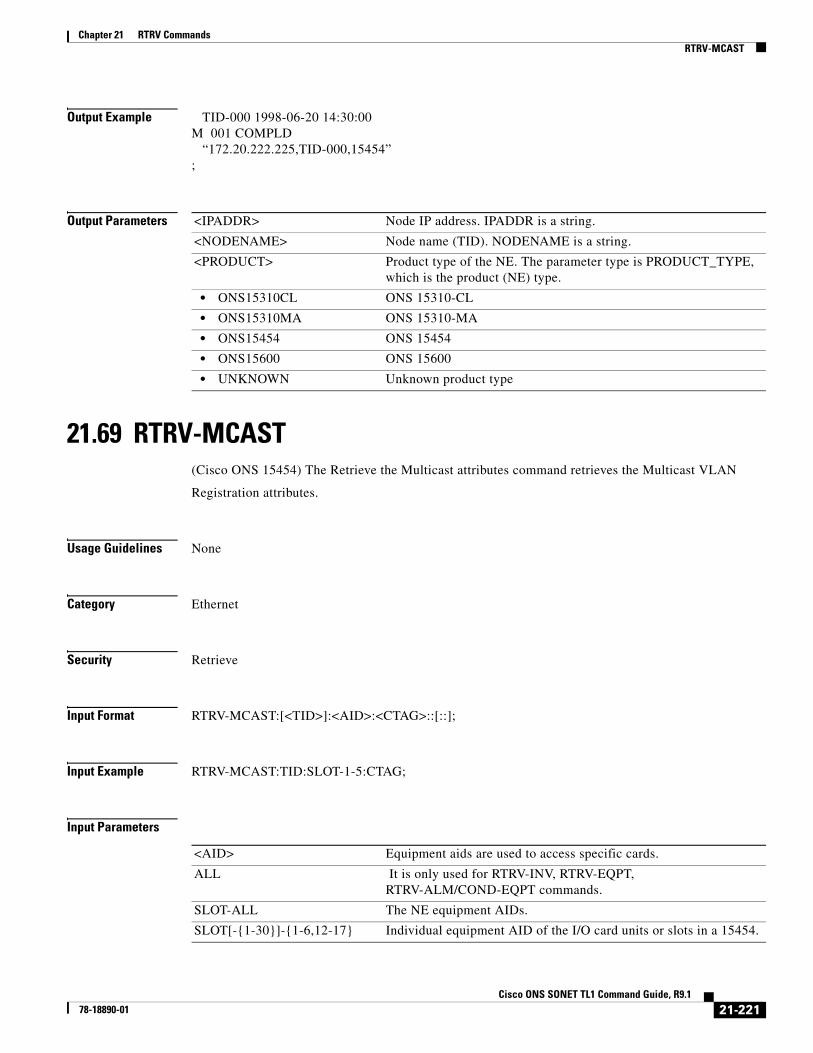
Chapter 21 RTRV CommandsRTRV-MCAST
Output Example TID-000 1998-06-20 14:30:00M 001 COMPLD “172.20.222.225,TID-000,15454”;
Output Parameters
21.69 RTRV-MCAST(Cisco ONS 15454) The Retrieve the Multicast attributes command retrieves the Multicast VLAN
Registration attributes.
Usage Guidelines None
Category Ethernet
Security Retrieve
Input Format RTRV-MCAST:[<TID>]:<AID>:<CTAG>::[::];
Input Example RTRV-MCAST:TID:SLOT-1-5:CTAG;
Input Parameters
<IPADDR> Node IP address. IPADDR is a string.
<NODENAME> Node name (TID). NODENAME is a string.
<PRODUCT> Product type of the NE. The parameter type is PRODUCT_TYPE, which is the product (NE) type.
• ONS15310CL ONS 15310-CL
• ONS15310MA ONS 15310-MA
• ONS15454 ONS 15454
• ONS15600 ONS 15600
• UNKNOWN Unknown product type
<AID> Equipment aids are used to access specific cards.
ALL It is only used for RTRV-INV, RTRV-EQPT, RTRV-ALM/COND-EQPT commands.
SLOT-ALL The NE equipment AIDs.
SLOT[-{1-30}]-{1-6,12-17} Individual equipment AID of the I/O card units or slots in a 15454.
21-221Cisco ONS SONET TL1 Command Guide, R9.1
78-18890-01
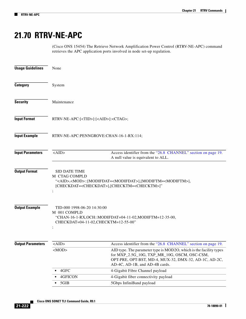
Chapter 21 RTRV CommandsRTRV-NE-APC
21.70 RTRV-NE-APC(Cisco ONS 15454) The Retrieve Network Amplification Power Control (RTRV-NE-APC) command retrieves the APC application ports involved in node set-up regulation.
Usage Guidelines None
Category System
Security Maintenance
Input Format RTRV-NE-APC:[<TID>]:[<AID>]:<CTAG>;
Input Example RTRV-NE-APC:PENNGROVE:CHAN-16-1-RX:114;
Input Parameters
Output Format SID DATE TIMEM CTAG COMPLD “<AID>,<MOD>::[MODIFDAT=<MODIFDAT>],[MODIFTM=<MODIFTM>], [CHECKDAT=<CHECKDAT>],[CHECKTM=<CHECKTM>]”;
Output Example TID-000 1998-06-20 14:30:00M 001 COMPLD “CHAN-16-1-RX,OCH::MODIFDAT=04-11-02,MODIFTM=12-35-00, CHECKDAT=04-11-02,CHECKTM=12-55-00”;
Output Parameters
<AID> Access identifier from the “26.8 CHANNEL” section on page 19. A null value is equivalent to ALL.
<AID> Access identifier from the “26.8 CHANNEL” section on page 19.
<MOD> AID type. The parameter type is MOD2O, which is the facility types for MXP_2.5G_10G, TXP_MR_10G, OSCM, OSC-CSM, OPT-PRE, OPT-BST, MD-4, MUX-32, DMX-32, AD-1C, AD-2C, AD-4C, AD-1B, and AD-4B cards.
• 4GFC 4-Gigabit Fibre Channel payload
• 4GFICON 4-Gigabit fiber connectivity payload
• 5GIB 5Gbps InfiniBand payload
21-222Cisco ONS SONET TL1 Command Guide, R9.1
78-18890-01

Chapter 21 RTRV CommandsRTRV-NE-GEN
21.71 RTRV-NE-GEN(Cisco ONS 15454, 15327, 15600, 15310) The Retrieve Network Element General (RTRV-NE-GEN) command retrieves the general NE attributes.
Usage Guidelines ETHIPADDR and ETHIPMASK are disabled in this command. ETHIPADDR and ETHIPMASK are used to show the Ethernet interface address and mask. Both default to the nodes’ IP address and masks.
Category System
Security Retrieve
Input Format RTRV-NE-GEN:[<TID>]::<CTAG>;
Input Example RTRV-NE-GEN:CISCO::123;
• 8GFC 8-Gigabit Fibre Channel payload
• ISC3PEER1G 1 Gbps ISC3 peer
• ISC3PEER2G 2 Gbps ISC3 peer
• ISC3PEER2R 1 Gbps ISC1, ISC2, and ISC3 compatibility
• ISCCOMPAT 1 Gbps or 2 Gbps ISC3 peer used in transparent (2R) mode
• OCH Optical channel
• OMS Optical multiplexer section
• OTS Optical trace section
• OTU3 Optical Transport Unit Level 3
<MODIFDAT> (Optional) The last date when the APC application modified this port. The format of MODIFDAT is MM-DD, where MM (month of year) ranges from 1 to 12 and DD (day of month) ranges from 1 to 31.
<MODIFTM> (Optional) The last time when the APC application modified this port. The format of MODIFTM is HH-MM, where HH (hour of day) ranges from 0 to 23 and MM (minute of hour) ranges from 0 to 59.
<CHECKDAT> (Optional) The last date when the APC application controlled and validated this port. The format of CHECKDAT is MM-DD, where MM (month of year) ranges from 1 to 12 and DD (day of month) ranges from 1 to 31.
<CHECKTM> (Optional) The last time when the APC application controlled and validated this port. The format of CHECKTM is HH-MM, where HH (hour of day) ranges from 0 to 23 and MM (minute of hour) ranges from 0 to 59.
21-223Cisco ONS SONET TL1 Command Guide, R9.1
78-18890-01

Chapter 21 RTRV CommandsRTRV-NE-GEN
Input Parameters None that require description
Output Format SID DATE TIMEM CTAG COMPLD “[IPADDR=<IPADDR>],[IPMASK=<IPMASK>],[DEFRTR=<DEFRTR>],[IPV6ADDR=<IPV6ADDR>],[IPV6PREFLEN=<IPV6PREFLEN>],[IPV6DEFRTR=<IPV6DEFRTR>],[IPV6ENABLE=<IPV6ENABLE>],[IIOPPORT=<IIOPPORT>],[NTP=<NTP>],[NAME=<NAME>],[SWVER=<SWVER>],[LOAD=<LOAD>],[PROTSWVER=<PROTSWVER>],[PROTLOAD=<PROTLOAD>],[DEFDESC=<DEFDESC>],[PLATFORM=<PLATFORM>],[SECUMODE=<SECUMODE>],[SUPPRESSIP=<SUPPRESSIP>],[MODE=<MODE>],[MSPUBVLANID=<MSPUBVLANID>],[MSINTLVLANID=<MSINTLVLANID>],[AUTOPM=<AUTOPM>], [SERIALPORTECHO=<SERIALPORTECHO>],[OSIROUTINGMODE=<OSIROUTINGMODE>], [OSIL1BUFSIZE=<OSIL1BUFSIZE>],[OSIL2BUFSIZE=<OSIL2BUFSIZE>], [NET=<NET>] >],[BKUPNTP=<BKUPNTP>];
Output Example TID-000 1998-06-20 14:30:00M 001 COMPLDIPADDR=192.168.100.52,IPMASK=255.255.255.0,DEFRTR=192.168.100.1, IPV6ADDR=“[3ffe:0501:0008:0000:0260:97ff:fe40:efab]”,IPV6PREFLEN=64,IPV6DEFRTR=“[3ffe:0501:0008:0000:0260:97ff:fe40:e000]”,IPV6ENABLE=NO IIOPPORT=57970,NTP=192.168.100.52,NAME="NODENAME",SWVER=2.01.03, LOAD=02.13-E09A-08.15,PROTSWVER=2.01.02,PROTLOAD=02.12-E09A-09.25, DEFDESC=\"NE DEFAULTS FEATURE\",PLATFORM=15454-ANSI,SECUMODE=NORMAL, SUPPRESSIP=YES,PROXYSRV=N,FIREWALL=N,MSPUBVLANID=1,MSINTLVLANID=2,AUTOPM=NO,SERIALPORTECHO=Y,OSIROUTINGMODE=ES,OSIL1BUFSIZE=512,OSIL2BUFSIZE=512”;
Output Parameters <IPADDR> (Optional) Node IP address. IPADDR is a string.
<IPMASK> (Optional) Node IP mask. IPMASK is a string.
<DEFRTR> (Optional) Node default router. DEFRTR is a string.
<IPV6ADDR> Specifies the IPv6 address of the NE. IPV6ADDR is a string.
Note IPV6ADDR parameter can be set only if IPV6ENABLE parameter is set to Y
<IPV6PREFLEN> Specifies the prefix length for the IPv6 address of the NE. IPV6PREFLEN is an integer.
<IPV6DEFRTR> Specifies the IPv6 default router address for the NE. IPV6DEFRTR is a string.
<IPV6ENABLE> Specifies if the IPv6 enable mode for the NE is enabled or disabled.
• Y Indicates that IPV6 mode is enabled.
• N Indicates that IPV6 mode is disabled.
<IIOPPORT> (Optional) Node IIOP port. IIPOOPRT is an integer.
21-224Cisco ONS SONET TL1 Command Guide, R9.1
78-18890-01
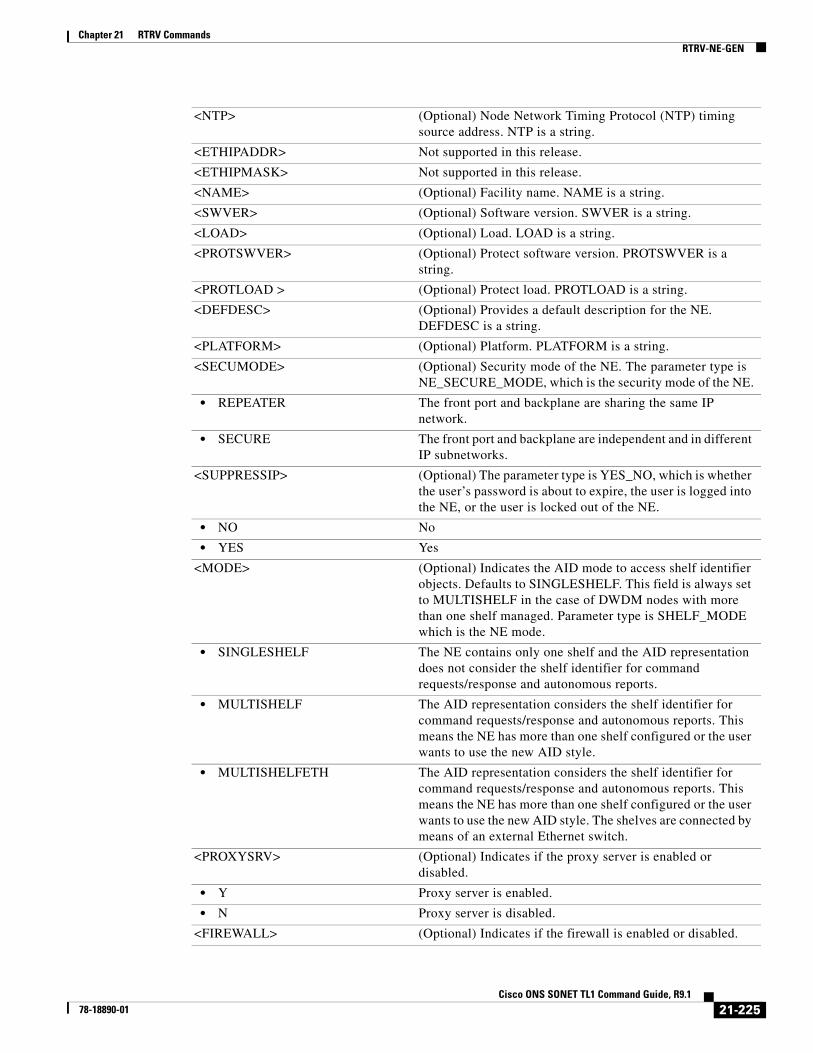
Chapter 21 RTRV CommandsRTRV-NE-GEN
<NTP> (Optional) Node Network Timing Protocol (NTP) timing source address. NTP is a string.
<ETHIPADDR> Not supported in this release.
<ETHIPMASK> Not supported in this release.
<NAME> (Optional) Facility name. NAME is a string.
<SWVER> (Optional) Software version. SWVER is a string.
<LOAD> (Optional) Load. LOAD is a string.
<PROTSWVER> (Optional) Protect software version. PROTSWVER is a string.
<PROTLOAD > (Optional) Protect load. PROTLOAD is a string.
<DEFDESC> (Optional) Provides a default description for the NE. DEFDESC is a string.
<PLATFORM> (Optional) Platform. PLATFORM is a string.
<SECUMODE> (Optional) Security mode of the NE. The parameter type is NE_SECURE_MODE, which is the security mode of the NE.
• REPEATER The front port and backplane are sharing the same IP network.
• SECURE The front port and backplane are independent and in different IP subnetworks.
<SUPPRESSIP> (Optional) The parameter type is YES_NO, which is whether the user’s password is about to expire, the user is logged into the NE, or the user is locked out of the NE.
• NO No
• YES Yes
<MODE> (Optional) Indicates the AID mode to access shelf identifier objects. Defaults to SINGLESHELF. This field is always set to MULTISHELF in the case of DWDM nodes with more than one shelf managed. Parameter type is SHELF_MODE which is the NE mode.
• SINGLESHELF The NE contains only one shelf and the AID representation does not consider the shelf identifier for command requests/response and autonomous reports.
• MULTISHELF The AID representation considers the shelf identifier for command requests/response and autonomous reports. This means the NE has more than one shelf configured or the user wants to use the new AID style.
• MULTISHELFETH The AID representation considers the shelf identifier for command requests/response and autonomous reports. This means the NE has more than one shelf configured or the user wants to use the new AID style. The shelves are connected by means of an external Ethernet switch.
<PROXYSRV> (Optional) Indicates if the proxy server is enabled or disabled.
• Y Proxy server is enabled.
• N Proxy server is disabled.
<FIREWALL> (Optional) Indicates if the firewall is enabled or disabled.
21-225Cisco ONS SONET TL1 Command Guide, R9.1
78-18890-01

Chapter 21 RTRV CommandsRTRV-NE-IPMAP
21.72 RTRV-NE-IPMAP(Cisco ONS 15454, 15327, 15600, 15310) The Retrieve Network Element Internet Protocol Map (RTRV-NE-IPMAP) command retrieves the IP address and node name of the NEs that have a DCC connection with this NE.
Usage Guidelines This command only reports the discovered DCC link. If there is no discovered DCC link on the port (or the node), the command will return COMPLD without IPMAP information.
Category Network
• Y Firewall is enabled.
• N Firewall is disabled.
<AUTOPM> (Optional) AUTOPM is a flag to indicate if autonomous PM reporting to TL1 clients is enabled or disabled.
• Y Auto PM reporting is enabled.
• N Auto PM reporting is disabled.
<SERIALPORTECHO> (Optional) Indicates if the echo is turned on for TL1 serial port sessions.
• Y Echo is turned on.
• N Echo is turned off.
<OSIROUTINGMODE> Indicates the routing mode of the node.
• ES Provisions the node as an OSI ES. The ONS node performs all ES functions and relies upon an IS for communication with other IS nodes inside and outside the ES OSI area.
• IS1 Provisions the node as an OSI IS. The ONS node performs all IS functions including routing data between ISs and ESs, between networks, and between parts of a network.
• IS2 The ONS node performs all IS functions. It communicates with other IS and ES nodes within an OSI area. It also broadcasts ISHs to IS nodes in other areas to which it is connected.
<OSIL1BUFSIZE> Level 1 Link State Protocol Data Unit (LSP) buffer size. The default is 512.
<OSIL2BUFSIZE> Level 2 Link State Protocol Data Unit (LSP) buffer size. The default is 512.
<NET> Network Entity Title of the node. The NET is used in OSI networks to identify the node to end system (ES) or intermediate system (IS) NEs. NETs are allocated from the same name space as the Network Service Address Point (NSAP) address. Whether an address is an NSAP or NET depends on the NSAP Selector value.
21-226Cisco ONS SONET TL1 Command Guide, R9.1
78-18890-01
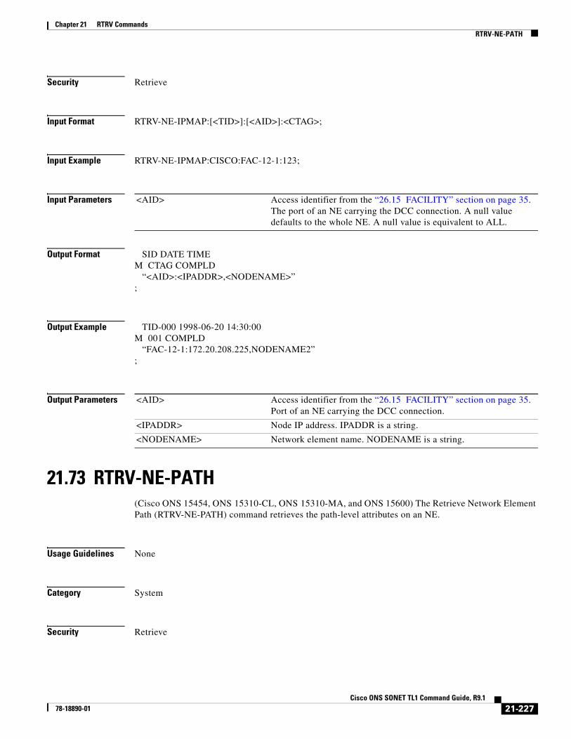
Chapter 21 RTRV CommandsRTRV-NE-PATH
Security Retrieve
Input Format RTRV-NE-IPMAP:[<TID>]:[<AID>]:<CTAG>;
Input Example RTRV-NE-IPMAP:CISCO:FAC-12-1:123;
Input Parameters
Output Format SID DATE TIMEM CTAG COMPLD “<AID>:<IPADDR>,<NODENAME>”;
Output Example TID-000 1998-06-20 14:30:00M 001 COMPLD “FAC-12-1:172.20.208.225,NODENAME2”;
Output Parameters
21.73 RTRV-NE-PATH(Cisco ONS 15454, ONS 15310-CL, ONS 15310-MA, and ONS 15600) The Retrieve Network Element Path (RTRV-NE-PATH) command retrieves the path-level attributes on an NE.
Usage Guidelines None
Category System
Security Retrieve
<AID> Access identifier from the “26.15 FACILITY” section on page 35. The port of an NE carrying the DCC connection. A null value defaults to the whole NE. A null value is equivalent to ALL.
<AID> Access identifier from the “26.15 FACILITY” section on page 35. Port of an NE carrying the DCC connection.
<IPADDR> Node IP address. IPADDR is a string.
<NODENAME> Network element name. NODENAME is a string.
21-227Cisco ONS SONET TL1 Command Guide, R9.1
78-18890-01
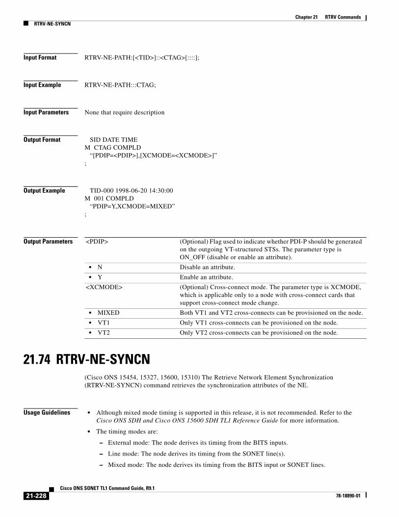
Chapter 21 RTRV CommandsRTRV-NE-SYNCN
Input Format RTRV-NE-PATH:[<TID>]::<CTAG>[::::];
Input Example RTRV-NE-PATH:::CTAG;
Input Parameters None that require description
Output Format SID DATE TIMEM CTAG COMPLD “[PDIP=<PDIP>],[XCMODE=<XCMODE>]”;
Output Example TID-000 1998-06-20 14:30:00M 001 COMPLD “PDIP=Y,XCMODE=MIXED”;
Output Parameters
21.74 RTRV-NE-SYNCN(Cisco ONS 15454, 15327, 15600, 15310) The Retrieve Network Element Synchronization (RTRV-NE-SYNCN) command retrieves the synchronization attributes of the NE.
Usage Guidelines • Although mixed mode timing is supported in this release, it is not recommended. Refer to the Cisco ONS SDH and Cisco ONS 15600 SDH TL1 Reference Guide for more information.
• The timing modes are:
– External mode: The node derives its timing from the BITS inputs.
– Line mode: The node derives its timing from the SONET line(s).
– Mixed mode: The node derives its timing from the BITS input or SONET lines.
<PDIP> (Optional) Flag used to indicate whether PDI-P should be generated on the outgoing VT-structured STSs. The parameter type is ON_OFF (disable or enable an attribute).
• N Disable an attribute.
• Y Enable an attribute.
<XCMODE> (Optional) Cross-connect mode. The parameter type is XCMODE, which is applicable only to a node with cross-connect cards that support cross-connect mode change.
• MIXED Both VT1 and VT2 cross-connects can be provisioned on the node.
• VT1 Only VT1 cross-connects can be provisioned on the node.
• VT2 Only VT2 cross-connects can be provisioned on the node.
21-228Cisco ONS SONET TL1 Command Guide, R9.1
78-18890-01

Chapter 21 RTRV CommandsRTRV-NE-SYNCN
Category Synchronization
Security Retrieve
Input Format RTRV-NE-SYNCN:[<TID>]:[<AID>]:<CTAG>[::::];
Input Example RTRV-NE-SYNCN:CISCO:SHELF-2:123;
Input Parameters
Output Format SID DATE TIMEM CTAG COMPLD “[<AID>]::[TMMD=<TMMD>],[SSMGEN=<SSMGEN>],[QRES=<QRES>], [RVRTV=<RVRTV>],[RVTM=<RVTM>],[SYSTMN=<SYSTMN>]”;
Output Example TID-000 1998-06-20 14:30:00M 001 COMPLD “SHELF-2::TMMD=LINE,SSMGEN=GEN1,QRES=ABOVE-G811,RVRTV=Y,RVTM=8.0,SYSTMN=SONET”;
Output Parameters
<AID> The node or shelf access identifier from the “26.24 SHELF” section on page 44. If omitted it addresses the node or first shelf of the node.
<AID> The node or shelf access identifier from the “26.24 SHELF” section on page 44. If omitted it addresses the node or first shelf of the node. Must not be null
<TMMD> (Optional) Timing mode. The parameter type is TIMING_MODE, which is the timing mode for the current node.
• EXTERNAL The node derives its clock from the BITS input.
• LINE The node derives its clock from the SONET lines.
• MIXED The node derives its clock from the mixed timing mode.
<SSMGEN> (Optional) Synchronization status message generator. The parameter type is SYNC_GENERATION, which is the synchronization status message set generation.
• GEN1 First generation SSM set
• GEN2 Second generation SSM set
<QRES> (Optional) Quality of the RES. The parameter type is SYNC_QUALITY_LEVEL, which is the network synchronization quality level.
21-229Cisco ONS SONET TL1 Command Guide, R9.1
78-18890-01
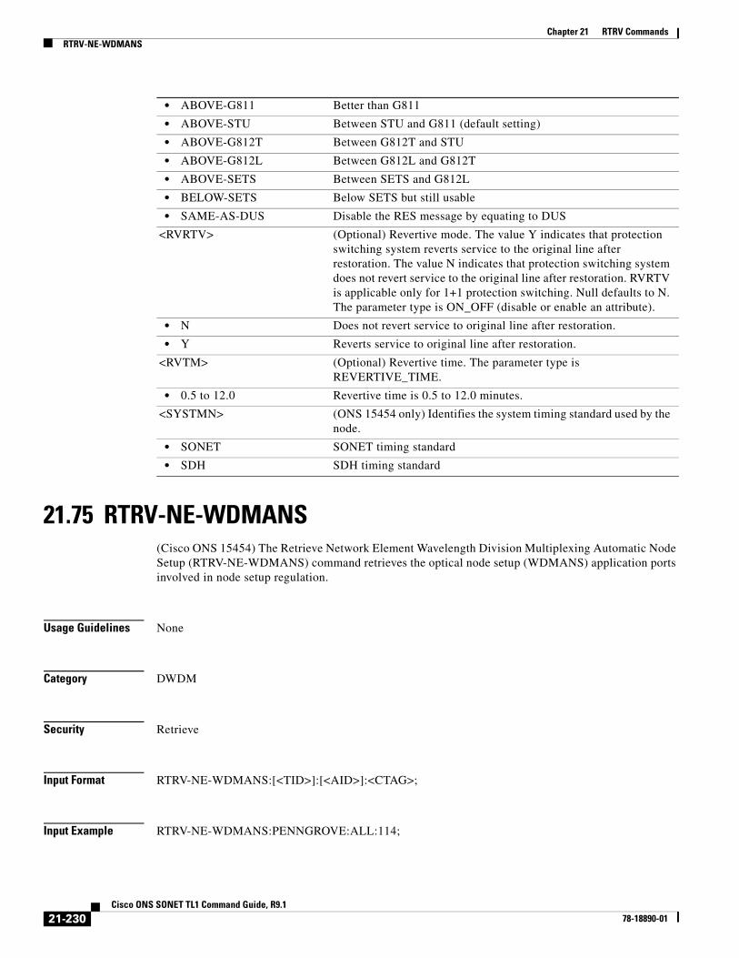
Chapter 21 RTRV CommandsRTRV-NE-WDMANS
21.75 RTRV-NE-WDMANS(Cisco ONS 15454) The Retrieve Network Element Wavelength Division Multiplexing Automatic Node Setup (RTRV-NE-WDMANS) command retrieves the optical node setup (WDMANS) application ports involved in node setup regulation.
Usage Guidelines None
Category DWDM
Security Retrieve
Input Format RTRV-NE-WDMANS:[<TID>]:[<AID>]:<CTAG>;
Input Example RTRV-NE-WDMANS:PENNGROVE:ALL:114;
• ABOVE-G811 Better than G811
• ABOVE-STU Between STU and G811 (default setting)
• ABOVE-G812T Between G812T and STU
• ABOVE-G812L Between G812L and G812T
• ABOVE-SETS Between SETS and G812L
• BELOW-SETS Below SETS but still usable
• SAME-AS-DUS Disable the RES message by equating to DUS
<RVRTV> (Optional) Revertive mode. The value Y indicates that protection switching system reverts service to the original line after restoration. The value N indicates that protection switching system does not revert service to the original line after restoration. RVRTV is applicable only for 1+1 protection switching. Null defaults to N. The parameter type is ON_OFF (disable or enable an attribute).
• N Does not revert service to original line after restoration.
• Y Reverts service to original line after restoration.
<RVTM> (Optional) Revertive time. The parameter type is REVERTIVE_TIME.
• 0.5 to 12.0 Revertive time is 0.5 to 12.0 minutes.
<SYSTMN> (ONS 15454 only) Identifies the system timing standard used by the node.
• SONET SONET timing standard
• SDH SDH timing standard
21-230Cisco ONS SONET TL1 Command Guide, R9.1
78-18890-01

Chapter 21 RTRV CommandsRTRV-NE-WDMANS
Input Parameters
Output Format SID DATE TIMEM CTAG COMPLD “<AID>,<AIDTYPE>::[REGULATED=<REGULATED>,][PARAM=<PARAM>]”;
Output Example TID-000 1998-06-20 14:30:00M 001 COMPLD “CHAN-16-1-RX,OCH::REGULATED=OUT-OF-RANGE,PARAM=VOAATTN”;
Output Parameters
<AID> The access identifier from the “26.1 ALL” section on page 1. A null value is equivalent to ALL.
<AID> Access identifier from the “26.1 ALL” section on page 1. AID is port regulated.
<AIDTYPE> Specifies the type of facility, link, or other addressable entity targeted by the message. A type of access identifier. The parameter type is MOD2, which is the line/path modifier.
• 10GFC 10-Gigabit Fibre Channel payload
• 10GFICON 10-Gigabit fiber connectivity payload
• 1GFC 1-Gigabit Fibre Channel payload
• 1GFICON 1-Gigabit fiber connectivity payload
• 1GISC3 1-Gigabit ISC3 compatible
• 2GFC 2-Gigabit Fibre Channel payload
• 2GFICON 2-Gigabit fiber connectivity payload
• 2GISC3 2-Gigabit ISC3 compatible
• 4GFC 4-Gigabit Fibre Channel payload
• 4GFICON 4-Gigabit fiber connectivity payload
• 5GIB 5Gbps InfiniBand payload
• 8GFC 8-Gigabit Fibre Channel payload
• D1VIDEO D1 video
• DS1 DS1 line of a DS3XM card
• DS3I DS3I line
• DV6000 DV6000
• EC1 EC1 facility
• ESCON ESCON
• ETRCLO ETR_CLO
• FSTE FSTE facility
• G1000 G1000 facility
• GFPOS GFP over POS. Virtual ports partitioned using GFP’s multiplexing capability.
• GIGE Gigabit Ethernet
21-231Cisco ONS SONET TL1 Command Guide, R9.1
78-18890-01

Chapter 21 RTRV CommandsRTRV-NE-WDMANS
• HDTV HDTV
• ISC3PEER1G 1 Gbps ISC3 Peer
• ISC3PEER2G 2 Gbps ISC3 Peer
• ISC3PEER2R 1 Gbps or 2 Gbps ISC3 peer used in transparent (2R) mode
• ISCCOMPAT 1 Gbps ISC1, ISC2, and ISC3 compatibility
• OC3 OC-3 facility
• OC12 OC-12 facility
• OC48 OC-48 facility
• OC192 OC-192 facility
• OCH Optical Channel
• OCHCC OCH client connection
• OCHNC OCH network connection
• OCHTERM OCH termination
• OMS Optical Multiplex Section
• OTS Optical Transport Section
• OTU3 Optical Transport Unit Level 3
• POS POS port
• STS1 STS1 path
• STS3C STS3c path
• STS6C STS6c path
• STS9C STS9c path
• STS18C STS18c path
• STS12C STS12c path
• STS24C STS24c path
• STS36C STS36c path
• STS48C STS48c path
• STS192C STS192c path
• T1 T1/DS1 facility/line
• T3 T1/DS1 facility/line
• VT1 VT1 path
• VT2 VT2 path
<REGULATED> (Optional) The status of the port after a node setup regulation. The parameter type is REGULATED_PORT_TYPE, which is the optical configuration types for NEs.
• FAILED WDM-ANS encountered a failure while regulating this port.
• MISSING-INPUT-PWR-PARAM
Missing input power parameter
• MISSING-OUTPUT-PWR-PARAM
Missing output power parameter
• NOT-APPLICABLE WDM-ANS does not foresee any algorithm or does not have any value to set for the parameter.
• OUT-OF-RANGE WDM-ANS cannot modify the set point because the calculated value is out of the allowed range.
21-232Cisco ONS SONET TL1 Command Guide, R9.1
78-18890-01
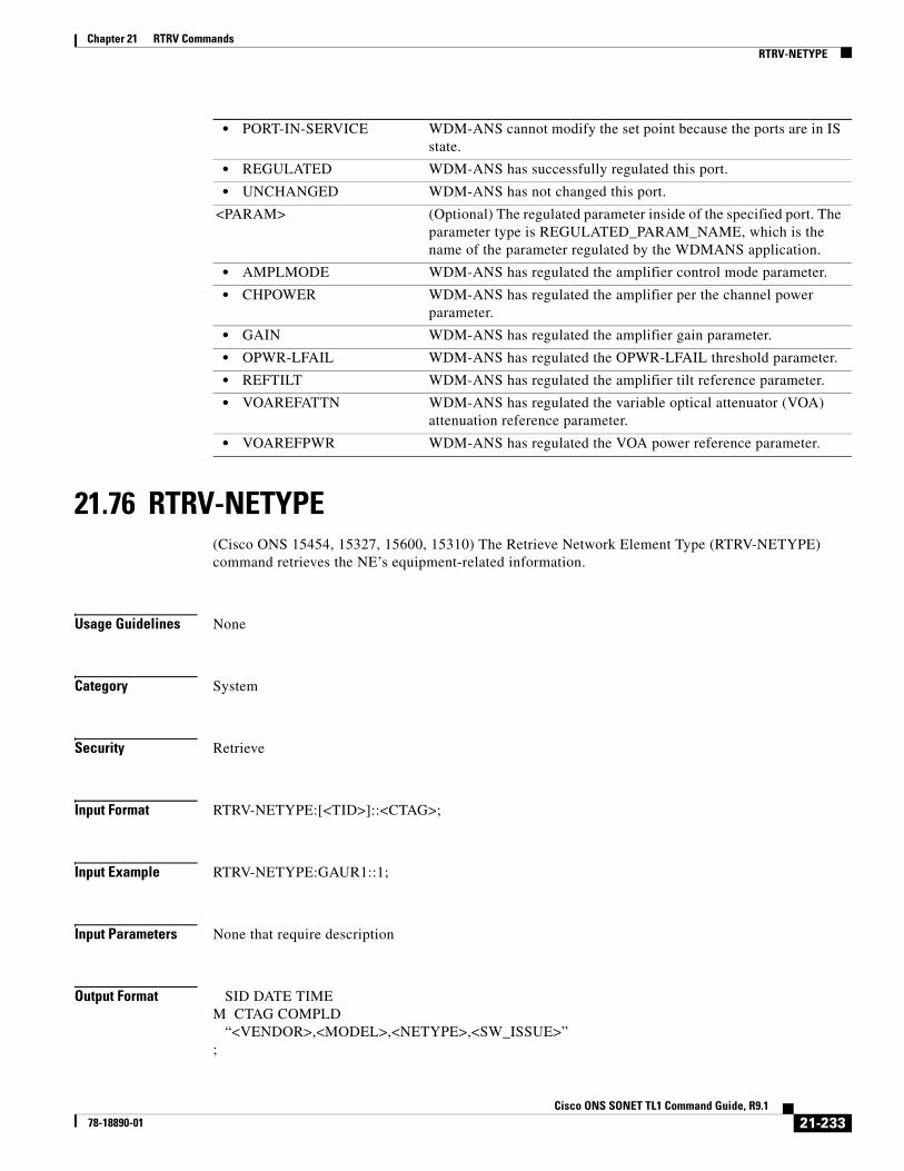
Chapter 21 RTRV CommandsRTRV-NETYPE
21.76 RTRV-NETYPE(Cisco ONS 15454, 15327, 15600, 15310) The Retrieve Network Element Type (RTRV-NETYPE) command retrieves the NE’s equipment-related information.
Usage Guidelines None
Category System
Security Retrieve
Input Format RTRV-NETYPE:[<TID>]::<CTAG>;
Input Example RTRV-NETYPE:GAUR1::1;
Input Parameters None that require description
Output Format SID DATE TIMEM CTAG COMPLD “<VENDOR>,<MODEL>,<NETYPE>,<SW_ISSUE>”;
• PORT-IN-SERVICE WDM-ANS cannot modify the set point because the ports are in IS state.
• REGULATED WDM-ANS has successfully regulated this port.
• UNCHANGED WDM-ANS has not changed this port.
<PARAM> (Optional) The regulated parameter inside of the specified port. The parameter type is REGULATED_PARAM_NAME, which is the name of the parameter regulated by the WDMANS application.
• AMPLMODE WDM-ANS has regulated the amplifier control mode parameter.
• CHPOWER WDM-ANS has regulated the amplifier per the channel power parameter.
• GAIN WDM-ANS has regulated the amplifier gain parameter.
• OPWR-LFAIL WDM-ANS has regulated the OPWR-LFAIL threshold parameter.
• REFTILT WDM-ANS has regulated the amplifier tilt reference parameter.
• VOAREFATTN WDM-ANS has regulated the variable optical attenuator (VOA) attenuation reference parameter.
• VOAREFPWR WDM-ANS has regulated the VOA power reference parameter.
21-233Cisco ONS SONET TL1 Command Guide, R9.1
78-18890-01
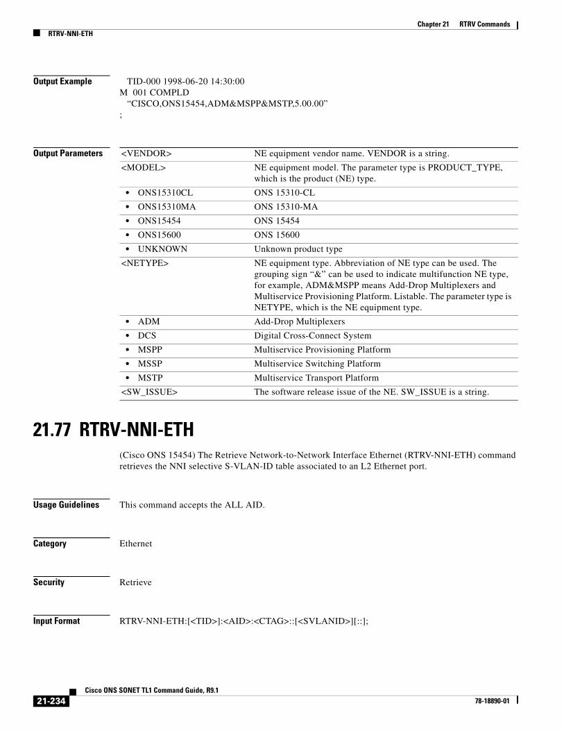
Chapter 21 RTRV CommandsRTRV-NNI-ETH
Output Example TID-000 1998-06-20 14:30:00M 001 COMPLD “CISCO,ONS15454,ADM&MSPP&MSTP,5.00.00”;
Output Parameters
21.77 RTRV-NNI-ETH(Cisco ONS 15454) The Retrieve Network-to-Network Interface Ethernet (RTRV-NNI-ETH) command retrieves the NNI selective S-VLAN-ID table associated to an L2 Ethernet port.
Usage Guidelines This command accepts the ALL AID.
Category Ethernet
Security Retrieve
Input Format RTRV-NNI-ETH:[<TID>]:<AID>:<CTAG>::[<SVLANID>][::];
<VENDOR> NE equipment vendor name. VENDOR is a string.
<MODEL> NE equipment model. The parameter type is PRODUCT_TYPE, which is the product (NE) type.
• ONS15310CL ONS 15310-CL
• ONS15310MA ONS 15310-MA
• ONS15454 ONS 15454
• ONS15600 ONS 15600
• UNKNOWN Unknown product type
<NETYPE> NE equipment type. Abbreviation of NE type can be used. The grouping sign “&” can be used to indicate multifunction NE type, for example, ADM&MSPP means Add-Drop Multiplexers and Multiservice Provisioning Platform. Listable. The parameter type is NETYPE, which is the NE equipment type.
• ADM Add-Drop Multiplexers
• DCS Digital Cross-Connect System
• MSPP Multiservice Provisioning Platform
• MSSP Multiservice Switching Platform
• MSTP Multiservice Transport Platform
<SW_ISSUE> The software release issue of the NE. SW_ISSUE is a string.
21-234Cisco ONS SONET TL1 Command Guide, R9.1
78-18890-01

Chapter 21 RTRV CommandsRTRV-OCM
Input Example RTRV-NNI-ETH:TID:ETH-1-1-1:CTAG::110;
Input Parameters
Output Format SID DATE TIMEM CTAG COMPLD “<AID>:<S_VLAN_ID>[::]”;
Output Example TID-000 1998-06-20 14:30:00M 001 COMPLD “ETH-1-1-1:110::”;
Output Parameters
21.78 RTRV-OCM
Note The RTRV-OCM command does not apply to the Cisco ONS 15600 and Cisco ONS 15310 MA platforms.
(Cisco ONS 15454) The Retrieve Optical Channel Monitoring (RTRV-OCM) command retrieves the optical channel monitoring parameters present at OCH layer in a ROADM node.
Usage Guidelines • Primary=Locked and secondary=AutomaticInService states do not apply to Ethernet mode.
Category DWDM
Security Retrieve
<AID> Ethernet AIDs are used to access L2 Ethernet ports. Access identifier from the “26.15 FACILITY” section on page 35.
<SVLANID> VLAN identifier. A VLAN ID is a number between 1 and 4096. The value 0 is reserved for untagged VLANs. This identifier is used for customer VLAN IDs and service provider VLAN IDs.
21-235Cisco ONS SONET TL1 Command Guide, R9.1
78-18890-01

Chapter 21 RTRV CommandsRTRV-OCH
Input Format RTRV-OCM:[<TID>]:<AID>:<CTAG>;
Input Example RTRV-OCM::OCM-1-16-1-RX-1530.33:12;
Input Parameters
Output Format SID DATE TIMEM CTAG COMPLD
"[<aid>]::[CHPOWER=<CHPOWER>];;
Output Example TID-000 1998-06-20 14:30:00M 001 COMPLD “ TID-000 1998-06-20 14:30:00M 001 COMPLD "OCM-1-16-1-RX-1530.33::CHPOWER=9.0”;
21.79 RTRV-OCH(Cisco ONS 15454) The Retrieve Optical Channel (RTRV-OCH) command retrieves the attributes (service parameters) and state of an OCH facility.
Usage Guidelines Refer to the Cisco ONS SDH and Cisco ONS 15600 SDH TL1 Reference Guide for specific card provisioning rules.
Note Primary=OOS and secondary=AINS states do not apply to Ethernet mode.
Category DWDM
Security Retrieve
<AID> Access identifier from the “26.8 CHANNEL” section on page 19.
Table 21-5 Output Parameter Support
Parameter DescriptionCisco ONS 15454
Cisco ONS 15600
Cisco ONS 15310 MA
<AID> Access identifier from the “26.8 CHANNEL” section on page 19.
Y N/A N/A
<CHPOWER> (Optional) The per channel optical power. Applicable only to amplified OTS ports.
Y N/A N/A
21-236Cisco ONS SONET TL1 Command Guide, R9.1
78-18890-01

Chapter 21 RTRV CommandsRTRV-OCH
Input Format RTRV-OCH:[<TID>]:<AID>:<CTAG>;
Input Example RTRV-OCH:PENNGROVE:CHAN-6-2:236;
Input Parameters
Output Format SID DATE TIMEM CTAG COMPLD “<AID>:,,[<ROLE>],[<STATUS>]:[<OPTICALPORTTYPE>],[<POWER>],[<EXPWLEN>],[<ACTWLEN>],[<ILOSS>],[<VOAMODE>],[<VOAATTN>],[<FCS>],[<VOAPWR>],[<VOAREFATTN>],[<VOAREFPWR>],[<REFOPWR>],[<CALOPWR>],[<CHPOWER>],[<CHPOWERFLG>],[<ADDOPWR>],[<ADDOPWR>],[<PORTNAME>],[<GCC>],[<GCCRATE>],[<DWRAP>],[<FEC>],[<PAYLOADMAP>],[<LBCLCURR>],[<OPTCURR>],[<OPRCURR>],[<OSFBER>],[<OSDBER>],[<SOAK>],[<SOAKLEFT>],[<LOSSB>],[<PEERID>],[<REGENNAME>],[<PORTMODE>],[<ODUTRANSMODE>],[<ERRORDECORRELATOR>]:<PST>,[<SST>]”;
Output Example TID-000 1998-06-20 14:30:00M 001 COMPLD “CHAN-6-1:,,WORK,ACT:OPTYPE=DROP,OPWR=10.0,EXPWLEN=1530.33,NAME="NY PORT",GCC=Y,GCCRATE=192K,DWRAP=Y,FEC=STD,PAYLOADMAP=ASYNCH,OSFBER=1E-4,OSDBER=1E-5,SOAK=52,SOAKLEFT=12-25,LBCL=10.0,OPT=10.0,OPR=10.0,LOSSB=DWDM,ERRORDECORRELATOR=Y:OOS-AU,AINS”;
Output Parameters
<AID> Access identifier from the “26.8 CHANNEL” section on page 19.
<AID> Access identifier from the “26.8 CHANNEL” section on page 19.
<ROLE> (Optional) Identifies an OCH port role. The parameter type is SIDE, which is the role the unit is playing in the protection group.
• PROT The entity is a protection unit in the protection group.
• WORK The entity is a working unit in the protection group.
<STATUS> (Optional) The port status. The parameter type is STATUS, which is the status of the unit in the protection pair.
• ACT The entity is the active unit in the shelf.
• NA Status is unavailable.
• STBY The entity is the standby unit in the shelf.
<OPTICALPORTTYPE> The optical port type. The parameter type is OPTICAL_PORT_TYPE, which qualifies the optical port of a card.
• ADD The signal is added to the port.
• COM Common Port
• DROP The signal is dropped from the port.
• EAD Express/Add/Drop port
21-237Cisco ONS SONET TL1 Command Guide, R9.1
78-18890-01

Chapter 21 RTRV CommandsRTRV-OCH
• IN-COM COM channels (without OSC) that continue the signal from the previous card
• IN-DC Input DCU port
• IN-EXP The express channel that continues the signal from the previous card
• IN-LINE All the channels that continue the signal from the previous card
• IN-OSC OSC channel that continues the signal from the previous card
• OUT-COM COM channels (without OSC) that continue the signal to the next card
• OUT-DC Output DCU port
• OUT-EXP Express channel that continues the signal to the next card
• OUT-LINE All the channels that continue the signal to the next card
<ACTWLEN> (Optional) The manufacturing optical wavelength for this port. Applicable only to the following cards: OSCM, OSC-CSM, OPT-PRE, OPT-BST, 4MD-xx.x, 32MUX, 32DMX, AD-1C-xx.x, AD-2C-xx.x, AD-4C-xx.x, AD-1B-xx.x, and AD-4B-xx.x. The parameter type is OPTICAL_WLEN, which is the optical wavelength.
<EXPWLEN> (Optional) Optical wavelength for this port. Applicable only to the following types of cards: optical service channel cards, optical amplifier cards, dispersion compensation units, multiplexer and demultiplexer cards, and optical add/drop multiplexing (OADM) cards. The parameter type is OPTICAL_WLEN, which is the optical wavelength.
• 1310 Wavelength 1310
• 1470 Wavelength 1470
• 1490 Wavelength 1490
• 1510 Wavelength 1510
• 1528.77 Wavelength 1528.77
• 1529.55 Wavelength 1529.55
• 1529.94 Wavelength 1529.94
• 1530 Wavelength 1530
• 1530.33 Wavelength 1530.33
• 1530.72 Wavelength 1530.72
• 1531.12 Wavelength 1531.12
• 1531.51 Wavelength 1531.51
• 1531.90 Wavelength 1531.90
• 1532.29 Wavelength 1532.29
• 1532.68 Wavelength 1532.68
• 1533.07 Wavelength 1533.07
• 1533.47 Wavelength 1533.47
• 1533.86 Wavelength 1533.86
• 1534.25 Wavelength 1534.25
• 1534.64 Wavelength 1534.64
• 1535.04 Wavelength 1535.04
21-238Cisco ONS SONET TL1 Command Guide, R9.1
78-18890-01

Chapter 21 RTRV CommandsRTRV-OCH
• 1535.43 Wavelength 1535.43
• 1535.82 Wavelength 1535.82
• 1536.22 Wavelength 1536.22
• 1536.61 Wavelength 1536.61
• 1537 Wavelength 1537
• 1537.40 Wavelength 1537.40
• 1537.79 Wavelength 1537.79
• 1538.19 Wavelength 1538.19
• 1538.58 Wavelength 1538.58
• 1538.98 Wavelength 1538.98
• 1539.37 Wavelength 1539.37
• 1539.77 Wavelength 1539.77
• 1540.16 Wavelength 1540.16
• 1540.56 Wavelength 1540.56
• 1540.95 Wavelength 1540.95
• 1541.35 Wavelength 1541.35
• 1541.75 Wavelength 1541.75
• 1542.14 Wavelength 1542.14
• 1542.35 Wavelength 1542.35
• 1542.54 Wavelength 1542.54
• 1542.94 Wavelength 1542.94
• 1543.33 Wavelength 1543.33
• 1543.73 Wavelength 1543.73
• 1544.13 Wavelength 1544.13
• 1544.53 Wavelength 1544.53
• 1544.92 Wavelength 1544.92
• 1545.32 Wavelength 1545.32
• 1545.72 Wavelength 1545.72
• 1546.12 Wavelength 1546.12
• 1546.52 Wavelength 1546.52
• 1546.92 Wavelength 1546.92
• 1547.32 Wavelength 1547.32
• 1547.72 Wavelength 1547.72
• 1548.11 Wavelength 1548.11
• 1548.51 Wavelength 1548.51
• 1548.91 Wavelength 1548.91
• 1549.32 Wavelength 1549.32
• 1549.72 Wavelength 1549.72
• 1550 Wavelength 1500
• 1550.12 Wavelength 1550.12
• 1550.52 Wavelength 1550.52
21-239Cisco ONS SONET TL1 Command Guide, R9.1
78-18890-01

Chapter 21 RTRV CommandsRTRV-OCH
• 1550.92 Wavelength 1550.92
• 1551.32 Wavelength 1551.32
• 1551.72 Wavelength 1551.72
• 1552.12 Wavelength 1552.12
• 1552.52 Wavelength 1552.52
• 1552.93 Wavelength 1552.93
• 1553.33 Wavelength 1553.33
• 1553.73 Wavelength 1553.73
• 1554.13 Wavelength 1554.13
• 1554.13 Wavelength 1554.13
• 1554.94 Wavelength 1554.94
• 1555.34 Wavelength 1555.34
• 1555.75 Wavelength 1555.75
• 1556.15 Wavelength 1556.15
• 1556.55 Wavelength 1556.55
• 1556.96 Wavelength 1556.96
• 1557.36 Wavelength 1557.36
• 1557.77 Wavelength 1557.77
• 1558.17 Wavelength 1558.17
• 1558.58 Wavelength 1558.58
• 1558.98 Wavelength 1558.98
• 1559.39 Wavelength 1559.39
• 1559.79 Wavelength 1559.79
• 1560.20 Wavelength 1560.20
• 1560.61 Wavelength 1560.61
• 1561.01 Wavelength 1561.01
• 1561.42 Wavelength 1561.42
• 1561.83 Wavelength 1561.83
• 1570 Wavelength 1570
• 1570.83 Wavelength 1570.83
• 1571.24 Wavelength 1571.24
• 1571.65 Wavelength 1571.65
• 1572.06 Wavelength 1572.06
• 1572.48 Wavelength 1572.48
• 1572.89 Wavelength 1572.89
• 1573.30 Wavelength 1573.30
• 1573.71 Wavelength 1573.71
• 1574.13 Wavelength 1574.13
• 1574.54 Wavelength 1574.54
• 1574.95 Wavelength 1574.95
• 1575.37 Wavelength 1575.37
21-240Cisco ONS SONET TL1 Command Guide, R9.1
78-18890-01

Chapter 21 RTRV CommandsRTRV-OCH
• 1575.78 Wavelength 1575.78
• 1576.20 Wavelength 1576.20
• 1576.61 Wavelength 1576.61
• 1577.03 Wavelength 1577.03
• 1577.44 Wavelength 1577.44
• 1577.86 Wavelength 1577.86
• 1578.27 Wavelength 1578.27
• 1578.69 Wavelength 1578.69
• 1579.10 Wavelength 1579.10
• 1579.52 Wavelength 1579.52
• 1579.93 Wavelength 1579.93
• 1580.35 Wavelength 1580.35
• 1580.77 Wavelength 1580.77
• 1581.18 Wavelength 1581.18
• 1581.60 Wavelength 1581.60
• 1582.02 Wavelength 1582.02
• 1582.44 Wavelength 1582.44
• 1582.85 Wavelength 1582.85
• 1583.27 Wavelength 1583.27
• 1583.69 Wavelength 1583.69
• 1584.11 Wavelength 1584.11
• 1584.53 Wavelength 1584.53
• 1584.95 Wavelength 1584.95
• 1585.36 Wavelength 1585.36
• 1585.78 Wavelength 1585.78
• 1586.20 Wavelength 1586.20
• 1586.62 Wavelength 1586.62
• 1587.04 Wavelength 1587.04
• 1587.46 Wavelength 1587.46
• 1587.88 Wavelength 1587.88
• 1588.30 Wavelength 1588.30
• 1588.73 Wavelength 1588.73
• 1589.15 Wavelength 1589.15
• 1589.57 Wavelength 1589.57
• 1589.99 Wavelength 1589.99
• 1590 Wavelength 1590
• 1590.41 Wavelength 1590.41
• 1590.83 Wavelength 1590.83
• 1591.26 Wavelength 1591.26
• 1591.68 Wavelength 1591.68
• 1592.10 Wavelength 1592.10
21-241Cisco ONS SONET TL1 Command Guide, R9.1
78-18890-01
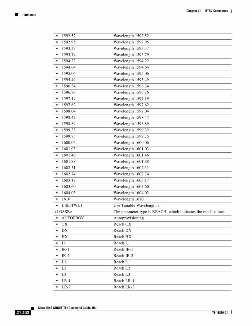
Chapter 21 RTRV CommandsRTRV-OCH
• 1592.52 Wavelength 1592.52
• 1592.95 Wavelength 1592.95
• 1593.37 Wavelength 1593.37
• 1593.79 Wavelength 1593.79
• 1594.22 Wavelength 1594.22
• 1594.64 Wavelength 1594.64
• 1595.06 Wavelength 1595.06
• 1595.49 Wavelength 1595.49
• 1596.34 Wavelength 1596.34
• 1596.76 Wavelength 1596.76
• 1597.19 Wavelength 1597.19
• 1597.62 Wavelength 1597.62
• 1598.04 Wavelength 1598.04
• 1598.47 Wavelength 1598.47
• 1598.89 Wavelength 1598.89
• 1599.32 Wavelength 1599.32
• 1599.75 Wavelength 1599.75
• 1600.06 Wavelength 1600.06
• 1601.03 Wavelength 1601.03
• 1601.46 Wavelength 1601.46
• 1601.88 Wavelength 1601.88
• 1602.31 Wavelength 1602.31
• 1602.74 Wavelength 1602.74
• 1603.17 Wavelength 1603.17
• 1603.60 Wavelength 1603.60
• 1604.03 Wavelength 1604.03
• 1610 Wavelength 1610
• USE-TWL1 Use Tunable Wavelength 1
<LOSSB> The parameter type is REACH, which indicates the reach values.
• AUTOPROV Autoprovisioning
• CX Reach CX
• DX Reach DX
• HX Reach HX
• I1 Reach I1
• IR-1 Reach IR-1
• IR-2 Reach IR-2
• L1 Reach L1
• L2 Reach L2
• L3 Reach L3
• LR-1 Reach LR-1
• LR-2 Reach LR-2
21-242Cisco ONS SONET TL1 Command Guide, R9.1
78-18890-01
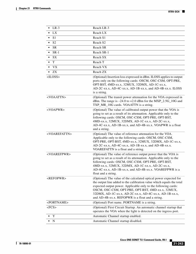
Chapter 21 RTRV CommandsRTRV-OCH
• LR-3 Reach LR-3
• LX Reach LX
• S1 Reach S1
• S2 Reach S2
• SR Reach SR
• SR-1 Reach SR-1
• SX Reach SX
• T Reach T
• VX Reach VX
• ZX Reach ZX
<ILOSS> (Optional) Insertion loss expressed in dBm. ILOSS applies to output ports only on the following cards: OSCM, OSC-CSM, OPT-PRE, OPT-BST, 4MD-xx.x, 32MUX, 32DMX, AD-1C-xx.x, AD-2C-xx.x, AD-4C-xx.x, AD-1B-xx.x, and AD-4B-xx.x. ILOSS is a string.
<VOAATTN> (Optional) The transit power attenuation for the VOA expressed in dBm. The range is –24.0 to +2.0 dBm for the MXP_2.5G_10G and TXP_MR_10G cards. VOAATTN is a string.
<VOAPWR> (Optional) The value of calibrated output power that the VOA is going to set as a result of its attenuation. Applicable only to the following cards: OSCM, OSC-CSM, OPT-PRE, OPT-BST, 4MD-xx.x, 32MUX, 32DMX, AD-1C-xx.x, AD-2C-xx.x, AD-4C-xx.x, AD-1B-xx.x, and AD-4B-xx.x. VOAPWR is a float and a string.
<VOAREFATTN> (Optional) The value of reference attenuation for the VOA. Applicable only to the following cards: OSCM, OSC-CSM, OPT-PRE, OPT-BST, 4MD-xx.x, 32MUX, 32DMX, AD-1C-xx.x, AD-2C-xx.x, AD-4C-xx.x, AD-1B-xx.x, and AD-4B-xx.x. VOAREFATTN is a float and a string.
<VOAREFPWR> (Optional) The value of reference output power that the VOA is going to set as a result of its attenuation. Applicable only to the following cards: OSCM, OSC-CSM, OPT-PRE, OPT-BST, 4MD-xx.x, 32MUX, 32DMX, AD-1C-xx.x, AD-2C-xx.x, AD-4C-xx.x, AD-1B-xx.x, and AD-4B-xx.x. VOAREFPWR is a float and a string.
<REFOPWR> (Optional) The value of the calculated optical power expected for the output line added to the calibration value which equals the total expected output power. Applicable only to the following cards: OSCM, OSC-CSM, OPT-PRE, OPT-BST, 4MD-xx.x, 32MUX, 32DMX, AD-1C-xx.x, AD-2C-xx.x, AD-4C-xx.x, AD-1B-xx.x, and AD-4B-xx.x. REFOPWR is a float and a string.
<PORTNAME> (Optional) Port name. PORTNAME is a string.
<FCS> (Optional) First Circuit Startup. An automatic channel startup that operates the VOA when the light is detected on the ingress port.
• Y Automatic Channel startup enabled.
• N Automatic Channel startup disabled.
21-243Cisco ONS SONET TL1 Command Guide, R9.1
78-18890-01

Chapter 21 RTRV CommandsRTRV-OCH
<CALOPWR> (Optional) The value of the calibrated optical power expected for the line added to the calculated value, which equals the total expected output power. Expressed in dBm. Defaults to 0 dBm. CALOPWR is a float.
<CHPOWERFLG> (Optional) Parameter status flag indicating the state of the channel power.
<ADDOPWR> (Optional) The value of the ADD optical power to an ADD port of the WSS card. The ADDOPWR is a float.
<GCC> Identifies the generic communication channel (GCC) connection of the port.
• Y GCC can be utilized.
• N GCC cannot be utilized.
<GCCRATE> (Optional) The data rate of the GCC traffic. The default is 192 Kbps. For MXP_2.5G_10G and TXP_MR_10G cards, this applies only to the DWDM port. The parameter type is GCCRATE, which is the data rate of the GCC traffic.
• 192K 192 Kbps
• 576K 576 Kbps
<DWRAP> (Optional) The ITU-T G.709 monitoring digital wrapper. It is either on or off. The system default is ON. For MXP_2.5G_10G and TXP_MR_10G cards, this applies only to the DWDM port. The parameter type is ON_OFF (disable or enable an attribute). To enable ITU-T G.709 monitoring, there should be no GCC on the DWDM port and the payload (in which the card is configured) should not be UNFRAMED. To disable ITU-T G.709 monitoring, there should be no GCC on the DWDM port, the FEC should be turned to off, there should be no overhead circuit created on the DWDM port, and none of the client ports on the card should be part of a Y-cable protection group (muxponder only).
• N Disable an attribute.
• Y Enable an attribute.
<PAYLOADMAP> (Optional) The type of payload mapping. It can be enabled only if ITU-T G.709 monitoring is turned ON and FEC is enabled. The parameter type is PAYLOAD_MAPPING, which is the payload mapping mode.
• ASYNCH Asynchronous mapping mode
• ODU ODU multiplex structure mode
• SYNCH Synchronous mapping mode
• NOOPU2FIXEDSTUFF Mapping with no FIXEDSTUFF
<FEC> (Optional) Forward error correction. It can be enabled only if ITU-T G.709 monitoring is turned ON. It is either off or enabled in standard or enhanced mode. The system default is standard FEC enabled. The FEC level PM and thresholds apply if the FEC is turned ON. The parameter type is FEC_MODE, which specifies the type of forward error correction.
• ENH Enhanced FEC is enabled.
• OFF FEC is disabled.
21-244Cisco ONS SONET TL1 Command Guide, R9.1
78-18890-01

Chapter 21 RTRV CommandsRTRV-OCH
• STD Standard FEC is enabled.
<PEERID> Indicates the peer trunk facility of the regeneration group on the OTU2-XP card. Accessed using the CHAN AID.
<REGENNAME> Indicates the name of a regeneration group. Applicable only to DWDM flavored cards, which support regeneration group. Regenname is a string. The default value is "NULL".
<PORTMODE> Describes the termination mode of each interface on the OTU2-XP card.
• DWDM-LINE Line terminating mode.
• DWDM-SECTION Section terminating mode.
• DWDM-TRANS-AIS Transprent mode AIS.
• DWDM-TRANS-SQUELCH Transparent mode squelch.
• 10GLANWAN-SQUELCH 10G LAN to WAN Squelch.
<ODUTRANSMODE> To configure the "ODUk OH" transparency on the OTU2-XP card.
• CISCO-EXT Cisco Extended. When the Cisco Extended configuration is selected, two bytes of the ODU layer is terminated to guarantee the interoperability with the older Transponder/Muxponder cards.
• TRANS-STD Transparent Standard Use. The transponder, behaving as a regenerator, terminates the OUT layer and is transparent to the ODU layer. Also in this case the FEC-MISM (FEC Mismatch) alarm is not generated.
<PST_PSTQ> Primary state of the entity. The parameter type is PST_PSTQ, which is the service state of the entity described by the PST and PSTQ.
• IS_NR In Service and Normal
• OOS-AU Out of Service and Autonomous
• OOS-AUMA Out of Service and Autonomous Management
• OOS-MA Out of Service and Management
<SSTQ> (Optional) Secondary state of the entity. The parameter type is SST, which provides additional information pertaining to PST and PSTQ.
• AINS Automatic In-Service
• DSBLD Disabled
• LPBK Loopback
• MEA Mismatch of Equipment
• MT Maintenance
• OOG Out of Group
• SWDL Software Download
• UAS Unassigned
• UEQ Unequipped
<ERRORDECORRELATOR> Indicates the presence of the MLSE modules on the card. This applies only to TXP_MR_10EX_C, MXP_2.5G_10EX_C, and MXP_MR_10DMEX_C cards
• Y Indicates that the MLSE module is enabled on the card.
• N Indicates that the MLSE module is disabled on the card.
21-245Cisco ONS SONET TL1 Command Guide, R9.1
78-18890-01

Chapter 21 RTRV CommandsRTRV-OCHCC
21.80 RTRV-OCHCC(Cisco ONS 15454) The Retrieve Optical Channel Client Connection (RTRV-OCHCC) command retrieves the OCH client connection provisioning information.
Usage Guidelines None
Category DWDM
Security Retrieve
Input Format RTRV-OCHCC:[<TID>]:<AID>:<CTAG>;
Input Example RTRV-OCHCC:VA454-22:FAC-2-1-1:116;
Input Parameters
Output Format SID DATE TIMEM CTAG COMPLD “<AID>::[PAYLOAD=<PAYLOAD>],[CTKID=<CTKID>]:<PSTPSTQ>”;
Output Example TID-000 1998-06-20 14:30:00M 001 COMPLD “FAC-2-1-1::PAYLOAD=OC192,CTKID=\"OCHCC\":IS-NR”;
Output Parameters
<AID> Access identifier from the “26.15 FACILITY” section on page 35.
<AID> Access identifier from the “26.8 CHANNEL” section on page 19.
<PAYLOAD> Indicates the payload of the connection which is equivalent to the type of the payload configured on the facility port where the connection is originated or terminated. Parameter type is MOD1PAYLOAD.
• 10GFC 10-Gigabit Fibre Channel payload
• 10GFICON 10-Gigabit fiber connectivity payload
• 1GFC 1-Gigabit Fibre Channel payload
• 1GFICON 1-Gigabit fiber connectivity payload
• 1GISC3 1-Gigabit ISC3 compatible
21-246Cisco ONS SONET TL1 Command Guide, R9.1
78-18890-01

Chapter 21 RTRV CommandsRTRV-OCHNC
21.81 RTRV-OCHNC(Cisco ONS 15454) The Retrieve Optical Channel Network Connection (RTRV-OCHNC) command retrieves the OCH wavelength connection provisioning information.
Usage Guidelines None
• 2GFC 2-Gigabit Fibre Channel payload
• 2GFICON 2-Gigabit fiber connectivity payload
• 2GISC3 2-Gigabit ISC3 compatible
• 4GFC 4-Gigabit Fibre Channel payload
• 4GFICON 4-Gigabit fiber connectivity payload
• 5GIB 5Gbps InfiniBand payload
• 8GFC 8-Gigabit Fibre Channel payload
• D1VIDEO D1Video payload
• DV6000 DV6000 payload
• EC1 EC1 payload
• ESCON ESCON payload
• ETRCLO ETRCLO payload
• GIGE 1 G Ethernet payload
• HDTV HDTV payload
• ISC3PEER1G 1 Gbps ISC3 Peer
• ISC3PEER2G 2 Gbps ISC3 Peer
• ISC3PEER2R 1 Gbps or 2 Gbps ISC3 peer used in transparent (2R) mode
• ISCCOMPAT 1 Gbps ISC1, ISC2, and ISC3 compatibility
• OC12 OC12 payload
• OC192 OC192 payload
• OC3 OC3 payload
• OC48 OC48 payload
• OTU3 Optical Transport Unit Level 3
• T3 DS3 payload
<CKTID> Cross-connect ID. The default is Blank or None. String of ASCII characters. Maximum length is 48. If CKTID is empty or null the CKTID field will not be displayed.
<PSTPSTQ> Service state. The parameter is PST_PSTQ, which provides the service state of the entity described by the PST and PSTQ.
• Unlocked-Enabled In service and normal
• Unlocked-Disabled Out of service and autonomous
• Locked-Disabled Out of service, autonomous and management
• Locked-Enabled Out of service and management
21-247Cisco ONS SONET TL1 Command Guide, R9.1
78-18890-01
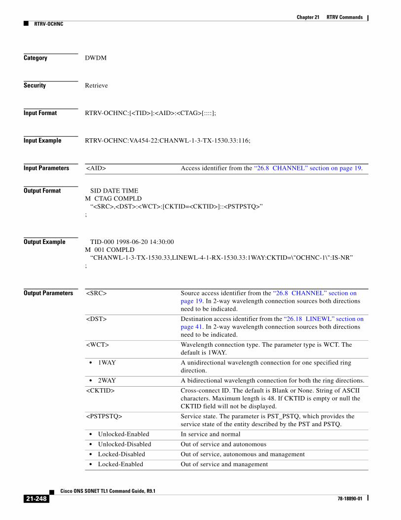
Chapter 21 RTRV CommandsRTRV-OCHNC
Category DWDM
Security Retrieve
Input Format RTRV-OCHNC:[<TID>]:<AID>:<CTAG>[::::];
Input Example RTRV-OCHNC:VA454-22:CHANWL-1-3-TX-1530.33:116;
Input Parameters
Output Format SID DATE TIMEM CTAG COMPLD “<SRC>,<DST>:<WCT>:[CKTID=<CKTID>]::<PSTPSTQ>”;
Output Example TID-000 1998-06-20 14:30:00M 001 COMPLD “CHANWL-1-3-TX-1530.33,LINEWL-4-1-RX-1530.33:1WAY:CKTID=\"OCHNC-1\":IS-NR”;
Output Parameters
<AID> Access identifier from the “26.8 CHANNEL” section on page 19.
<SRC> Source access identifier from the “26.8 CHANNEL” section on page 19. In 2-way wavelength connection sources both directions need to be indicated.
<DST> Destination access identifier from the “26.18 LINEWL” section on page 41. In 2-way wavelength connection sources both directions need to be indicated.
<WCT> Wavelength connection type. The parameter type is WCT. The default is 1WAY.
• 1WAY A unidirectional wavelength connection for one specified ring direction.
• 2WAY A bidirectional wavelength connection for both the ring directions.
<CKTID> Cross-connect ID. The default is Blank or None. String of ASCII characters. Maximum length is 48. If CKTID is empty or null the CKTID field will not be displayed.
<PSTPSTQ> Service state. The parameter is PST_PSTQ, which provides the service state of the entity described by the PST and PSTQ.
• Unlocked-Enabled In service and normal
• Unlocked-Disabled Out of service and autonomous
• Locked-Disabled Out of service, autonomous and management
• Locked-Enabled Out of service and management
21-248Cisco ONS SONET TL1 Command Guide, R9.1
78-18890-01
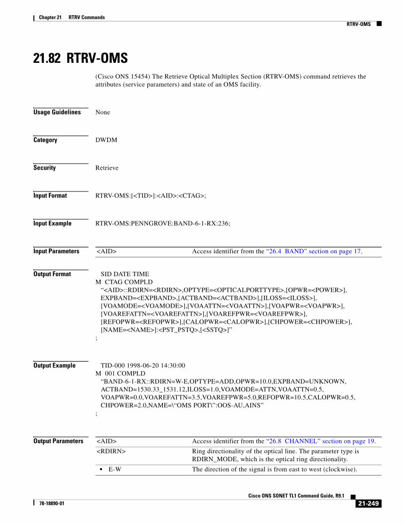
Chapter 21 RTRV CommandsRTRV-OMS
21.82 RTRV-OMS(Cisco ONS 15454) The Retrieve Optical Multiplex Section (RTRV-OMS) command retrieves the attributes (service parameters) and state of an OMS facility.
Usage Guidelines None
Category DWDM
Security Retrieve
Input Format RTRV-OMS:[<TID>]:<AID>:<CTAG>;
Input Example RTRV-OMS:PENNGROVE:BAND-6-1-RX:236;
Input Parameters
Output Format SID DATE TIMEM CTAG COMPLD “<AID>::RDIRN=<RDIRN>,OPTYPE=<OPTICALPORTTYPE>,[OPWR=<POWER>], EXPBAND=<EXPBAND>,[ACTBAND=<ACTBAND>],[ILOSS=<ILOSS>], [VOAMODE=<VOAMODE>],[VOAATTN=<VOAATTN>],[VOAPWR=<VOAPWR>], [VOAREFATTN=<VOAREFATTN>],[VOAREFPWR=<VOAREFPWR>], [REFOPWR=<REFOPWR>],[CALOPWR=<CALOPWR>],[CHPOWER=<CHPOWER>], [NAME=<NAME>]:<PST_PSTQ>,[<SSTQ>]”;
Output Example TID-000 1998-06-20 14:30:00M 001 COMPLD “BAND-6-1-RX::RDIRN=W-E,OPTYPE=ADD,OPWR=10.0,EXPBAND=UNKNOWN, ACTBAND=1530.33_1531.12,ILOSS=1.0,VOAMODE=ATTN,VOAATTN=0.5, VOAPWR=0.0,VOAREFATTN=3.5,VOAREFPWR=5.0,REFOPWR=10.5,CALOPWR=0.5, CHPOWER=2.0,NAME=\“OMS PORT\”:OOS-AU,AINS”;
Output Parameters
<AID> Access identifier from the “26.4 BAND” section on page 17.
<AID> Access identifier from the “26.8 CHANNEL” section on page 19.
<RDIRN> Ring directionality of the optical line. The parameter type is RDIRN_MODE, which is the optical ring directionality.
• E-W The direction of the signal is from east to west (clockwise).
21-249Cisco ONS SONET TL1 Command Guide, R9.1
78-18890-01

Chapter 21 RTRV CommandsRTRV-OMS
• W-E The direction of the signal is from west to east (counterclockwise).
<OPTICALPORTTYPE> The optical port type. The parameter type is OPTICAL_PORT_TYPE, which qualifies the optical port of a card.
• ADD The signal is added to the port.
• COM Common Port
• DROP The signal is dropped from the port.
• EAD Express/Add/Drop port
• IN-COM COM channels (without an OSC) that continue the signal from the previous card.
• IN-DC Input dispersion compensation unit (DCU) port.
• IN-EXP Express channel that continues the signal from the previous card.
• IN-LINE All the channels that continue the signal from the previous card.
• IN-OSC OSC channel that continues the signal from the previous card.
• OUT-COM COM channels (without an OSC) that continue the signal to the next card.
• OUT-DC Output DCU port.
• OUT-EXP Express channel that continues the signal to the next card.
• OUT-LINE All the channels that continue the signal to the next card.
• OUT-OSC OSC channel that continue the signal to the next card.
<POWER> (Optional) The optical power measured at this port. It can be the input or output power according to port type. POWER is a string.
<EXPBAND> The expected value of the band for this port. The parameter type is OPTICAL_BAND (optical band).
• 1530.33 to 1532.68 Band 1
• 1534.25 to 1536.61 Band 2
• 1538.19 to 1540.56 Band 3
• 1542.14 to 1544.53 Band 4
• 1546.12 to 1548.51 Band 5
• 1550.12 to 1552.52 Band 6
• 1554.13 to 1556.55 Band 7
• 1558.17 to 1560.61 Band 8
• USE-DEFAULT This band is not yet configured/retrieved from unit.
<ACTBAND> (Optional) Identifies the manufacturing optical band (group of four contiguous wavelengths) for this port. The parameter type is OPTICAL_BAND (optical band).
• 1530.33 to 1532.68 Band 1
• 1534.25 to 1536.61 Band 2
• 1538.19 to 1540.56 Band 3
• 1542.14 to 1544.53 Band 4
• 1546.12 to 1548.51 Band 5
• 1550.12 to 1552.52 Band 6
• 1554.13 to 1556.55 Band 7
• 1558.17 to 1560.61 Band 8
21-250Cisco ONS SONET TL1 Command Guide, R9.1
78-18890-01

Chapter 21 RTRV CommandsRTRV-OMS
• USE-DEFAULT This band is not yet configured/retrieved from unit.
<ILOSS> (Optional) Insertion loss expressed in dBm. ILOSS applies to output ports only.
<VOAMODE> (Optional) The working control mode of the VOA. The parameter type is VOA_CNTR_MODE, which defines the VOA control mode.
• ATTN VOA has a fixed attenuation.
• POWER VOA controls the attenuation to obtain a fixed output power.
<VOAATTN> (Optional) The value of calibrated attenuation for the VOA. VOAATTN is a float and a string.
<VOAPWR> (Optional) The value of calibrated output power that the VOA is going to set as a result of its attenuation. VOAPWR is a float and a string.
<VOAREFATTN> (Optional) The value of reference attenuation for the VOA. VOAREFATTN is a float and a string.
<VOAREFPWR> (Optional) The value of reference output power that the VOA is going to set as a result of its attenuation. VOAREFPWR is a float and a string.
<REFOPWR> (Optional) The value of the calculated optical power expected for the output line added to the calibration value which equals the total expected output power. REFOPWR is a float and a string.
<CALOPWR> (Optional) The value of the calibrated optical power expected for the output added to the calculated value, which equals the total expected output power. Expressed in dBm. Defaults to 0 dBm. CALOPWR is a float and a string.
<CHPOWER> (Optional) The per-channel optical power. The parameter type is REVERTIVE_TIME.
• 0.5 to 12.0 Revertive time is 0.5 to 12.0 minutes.
<NAME> (Optional) Facility name. NAME is a string.
<PST_PSTQ> Primary state of the entity. The parameter type is PST_PSTQ, which is the service state of the entity described by the primary state (PST) and a primary state qualifier (PSTQ).
• IS_NR In Service and Normal
• OOS-AU Out of Service and Autonomous
• OOS-AUMA Out of Service and Autonomous Management
• OOS-MA Out of Service and Management
<SSTQ> (Optional) Secondary state of the entity. The parameter type is SST, which provides additional information pertaining to PST and PSTQ.
• AINS Automatic In-Service
• DSBLD Disabled
• LPBK Loopback
• MEA Mismatch of Equipment
• MT Maintenance
• OOG Out of Group
• SWDL Software Download
21-251Cisco ONS SONET TL1 Command Guide, R9.1
78-18890-01
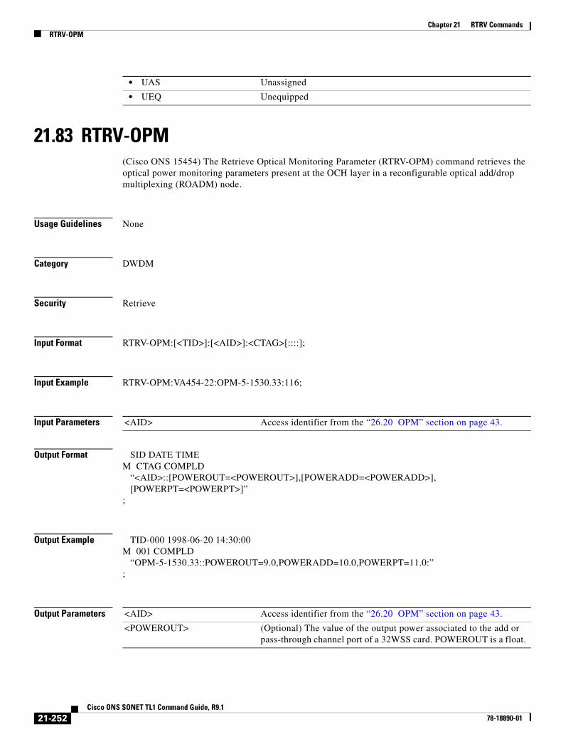
Chapter 21 RTRV CommandsRTRV-OPM
21.83 RTRV-OPM(Cisco ONS 15454) The Retrieve Optical Monitoring Parameter (RTRV-OPM) command retrieves the optical power monitoring parameters present at the OCH layer in a reconfigurable optical add/drop multiplexing (ROADM) node.
Usage Guidelines None
Category DWDM
Security Retrieve
Input Format RTRV-OPM:[<TID>]:[<AID>]:<CTAG>[::::];
Input Example RTRV-OPM:VA454-22:OPM-5-1530.33:116;
Input Parameters
Output Format SID DATE TIMEM CTAG COMPLD “<AID>::[POWEROUT=<POWEROUT>],[POWERADD=<POWERADD>], [POWERPT=<POWERPT>]”;
Output Example TID-000 1998-06-20 14:30:00M 001 COMPLD “OPM-5-1530.33::POWEROUT=9.0,POWERADD=10.0,POWERPT=11.0:”;
Output Parameters
• UAS Unassigned
• UEQ Unequipped
<AID> Access identifier from the “26.20 OPM” section on page 43.
<AID> Access identifier from the “26.20 OPM” section on page 43.
<POWEROUT> (Optional) The value of the output power associated to the add or pass-through channel port of a 32WSS card. POWEROUT is a float.
21-252Cisco ONS SONET TL1 Command Guide, R9.1
78-18890-01
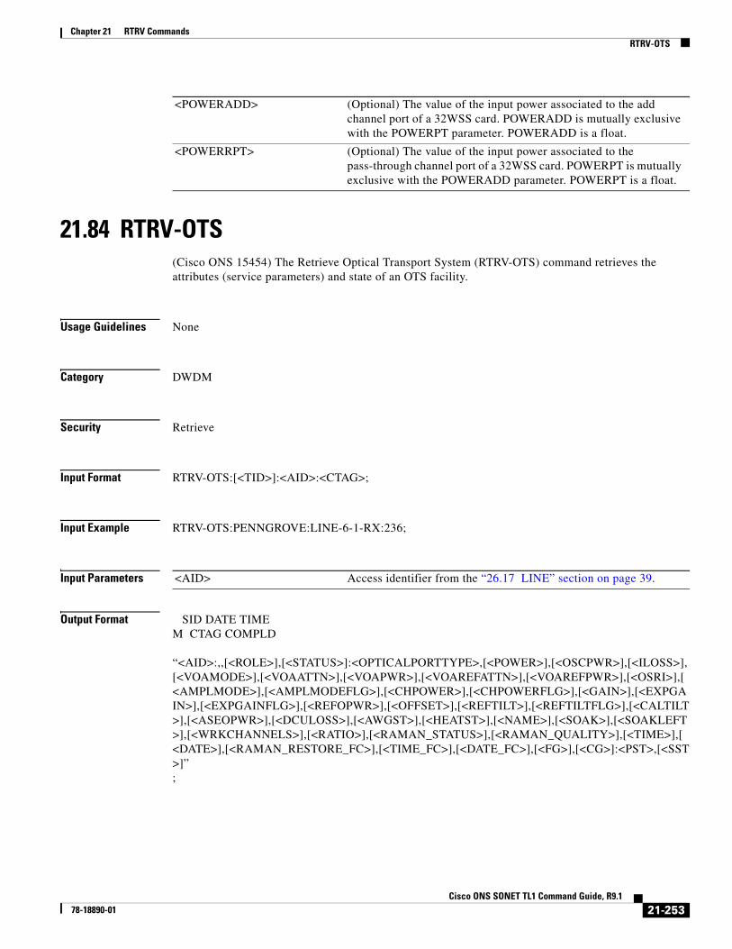
Chapter 21 RTRV CommandsRTRV-OTS
21.84 RTRV-OTS(Cisco ONS 15454) The Retrieve Optical Transport System (RTRV-OTS) command retrieves the attributes (service parameters) and state of an OTS facility.
Usage Guidelines None
Category DWDM
Security Retrieve
Input Format RTRV-OTS:[<TID>]:<AID>:<CTAG>;
Input Example RTRV-OTS:PENNGROVE:LINE-6-1-RX:236;
Input Parameters
Output Format SID DATE TIMEM CTAG COMPLD “<AID>:,,[<ROLE>],[<STATUS>]:<OPTICALPORTTYPE>,[<POWER>],[<OSCPWR>],[<ILOSS>],[<VOAMODE>],[<VOAATTN>],[<VOAPWR>],[<VOAREFATTN>],[<VOAREFPWR>],[<OSRI>],[<AMPLMODE>],[<AMPLMODEFLG>],[<CHPOWER>],[<CHPOWERFLG>],[<GAIN>],[<EXPGAIN>],[<EXPGAINFLG>],[<REFOPWR>],[<OFFSET>],[<REFTILT>],[<REFTILTFLG>],[<CALTILT>],[<ASEOPWR>],[<DCULOSS>],[<AWGST>],[<HEATST>],[<NAME>],[<SOAK>],[<SOAKLEFT>],[<WRKCHANNELS>],[<RATIO>],[<RAMAN_STATUS>],[<RAMAN_QUALITY>],[<TIME>],[<DATE>],[<RAMAN_RESTORE_FC>],[<TIME_FC>],[<DATE_FC>],[<FG>],[<CG>]:<PST>,[<SST>]”;
<POWERADD> (Optional) The value of the input power associated to the add channel port of a 32WSS card. POWERADD is mutually exclusive with the POWERPT parameter. POWERADD is a float.
<POWERRPT> (Optional) The value of the input power associated to the pass-through channel port of a 32WSS card. POWERPT is mutually exclusive with the POWERADD parameter. POWERPT is a float.
<AID> Access identifier from the “26.17 LINE” section on page 39.
21-253Cisco ONS SONET TL1 Command Guide, R9.1
78-18890-01

Chapter 21 RTRV CommandsRTRV-OTS
Output Example TID-000 1998-06-20 14:30:00M 001 COMPLD “LINE-6-1-RX:RDIRN=W-E,OPTYPE=IN,OPWR=10.0,ILOSS=1.0,VOAMODE=ATTN, VOAATTN=0.5,VOAPWR=0.0,VOAREFATTN=3.5,VOAREFPWR=5.0,OSRI=Y, AMPLMODE=GAIN,CHPOWER=-10.0,GAIN=3.0,EXPGAIN=3.0,REFOPWR=10.0, OFFSET=0.0,REFTILT=3.0,CALTILT=0.0,ASEOPWR=5.0,DCULOSS=1.2, AWGST=WARM-UP,HEATST=ON,NAME=\“OTS PORT\”:OOS-AU,AINS”;
Output Parameters <AID> Access identifier from the “26.17 LINE” section on page 39.
<RDIRN> Ring direction of the optical line. The parameter type is RDIRN_MODE, which is the optical ring direction.
• E-W The direction of the signal is from east to west (clockwise).
• W-E The direction of the signal is from west to east (counterclockwise).
<ROLE> The role the unit is playing in the protection group.
• PROT The entity is the protection unit in the protection group.
• WORK The entity is the working unit in the protection group.
<STATUS> The status of the unit in the protection pair.
• ACT The entity is the active unit on the shelf
• STBY The entity is the standby unit on the shelf
<OPTICALPORTTYPE> The optical port type. The parameter type is OPTICAL_PORT_TYPE, which qualifies the optical port of a card.
• ADD The signal is added to the port.
• COM Common port
• DROP The signal is dropped from the port.
• EAD Express/Add/Drop port
• IN-COM COM channels (without OSC) that continue the signal from the previous card
• IN-DC Input DCU port
• IN-EXP The express channel that continues the signal from the previous card
• IN-LINE All the channels that continue the signal from the previous card
• IN-OSC OSC channel that continues the signal from the previous card
• IN-RAMAN Input RAMAN line facility
• OUT-COM COM channels (without OSC) that continue the signal to the next card
• OUT-DC Output DCU port.
• OUT-EXP Express channel that continues the signal to the next card
• OUT-LINE All the channels that continue the signal to the next card
• OUT-OSC OSC channel that continue the signal to the next card
• OUT-RAMAN Output RAMAN line facility
<POWER> (Optional) The optical power measured at this port. It can be the input or output power according to port type. POWER is a float.
21-254Cisco ONS SONET TL1 Command Guide, R9.1
78-18890-01

Chapter 21 RTRV CommandsRTRV-OTS
<OSCPWR> (Optional) The optical power of the OSC channel inside the OTS port.
<ILOSS> (Optional) Insertion loss.
<VOAMODE> (Optional) The working control mode of the VOA. The parameter type is VOA_CNTR_MODE, which defines the VOA control mode.
• ATTN VOA has a fixed attenuation.
• POWER VOA controls the attenuation to obtain a fixed output power.
<VOAATTN> (Optional) The value of calibrated attenuation for the VOA. VOAATTN is a float.
<VOAPWR> (Optional) The value of calibrated output power that the VOA is going to set as a result of its attenuation. VOAPWR is a float.
<VOAREFATTN> (Optional) The value of reference attenuation for the VOA. VOAREFATTN is a float.
<VOAREFPWR> (Optional) The value of reference output power that the VOA is going to set as a result of its attenuation. VOAREFPWR is a float.
<OSRI> (Optional) OSRI enabled or disabled. Present only on a port where the safety is supported. Defaults to off. The parameter type is ON_OFF (disable or enable an attribute).
• N Disable an attribute.
• Y Enable an attribute.
<AMPLMODE> (Optional) The optical amplification control mode. The parameter type is AMPL_MODE, which defines amplifier control mode.
• GAIN The amplifier always maintains a fixed gain.
• POWER The amplifier maintains the output power to a fixed value.
<AMPLMODEFLG> (Optional) Parameter status flag indicating the state of the amplifier control mode.
<CHPOWER> (Optional) The per channel optical power. Applicable only to amplified OTS ports.
<CHPOWERFLG> (Optional) Parameter status flag indicating the state of the channel power.
<GAIN> (Optional) The value of the gain of the amplifier. Defaults to 21 dB for a preamplifier and 20 dB for a booster amplifier.
<EXPGAIN> (Optional) The expected gain value to be reached from an amplifier when the node is in a DWDM access network. EXPGAIN is a float.
<EXPGAINFLG> Parameter status flag indicating the state of the expected gain.
<REFOPWR> (Optional) The value of the calculated optical power expected for the output line added to the calibration value, which equals the total expected output power. REFOPWR is a float.
<OFFSET> (Optional) The value of the calibrated optical power expected for the output line, which is added to the calculated value to have the total expected output power. OFFSET is a float.
<REFTILT> (Optional) The calculated tilt value to be added to the user provided calibration value. REFTILT is a float.
<REFTILTFLG> Parameter status flag indicating the state of the calculated tilt.
<CALTILT> (Optional) The amplifier calibration tilt offset to be added to the calculated reference value. CALTILT is a float.
21-255Cisco ONS SONET TL1 Command Guide, R9.1
78-18890-01

Chapter 21 RTRV CommandsRTRV-OTS
<ASEOPWR> (Optional) The value of the calibrated optical power expected for the output line which is provided by the user, added to the calculated value to have the total expected output power. ASEOPWR is a float.
<DCULOSS> (Optional) The value of insertion loss associated to DCU in between the two stages of a preamplifier unit. DCULOSS is a float.
<AWGST> (Optional) The status assumed by arrayed waveguide grating (AWG). The parameter value is AWG_STATUS, which is the AWG status list.
• ON The AWG is on.
• WARM-UP The AWG is warming up.
<HEATST> (Optional) The status assumed by the heater. The parameter type is HEATER_STATUS, which is the heater status list.
• OFF The heater is off.
• ON The heater is on.
<NAME> (Optional) Port name. NAME is a string.
<SOAK> (Optional) Locked-Automatic In Service to Unlocked transition soak time as measured in 15-minute intervals. SOAK is an integer.
<SOAKLEFT> (Optional) Time remaining for the transition from Locked-AutomaticInService to Unlocked measured in 1 minute intervals. The format is HH-MM where HH ranges from 00 to 48 and MM ranges from 00 to 59. Rules for SOAKLEFT are as follows:
• When the port is in Locked;Locked,Maintenance; or Unlocked state, the parameter is not displayed.
• When the port is in Locked,AutomaticInService state but the countdown has not started due to a fault signal, the value will be SOAKLEFT=NOT-STARTED.
• When the port is in Locked,AutomaticInService state and the countdown has started, the value will be shown in HH-MM format.
<WRKCHANNELS> Number of working OCHNC channels carried by the facility.
<RATIO> Indicates the Raman Pump Power ratio.
<RAMAN_STATUS> Indicates the Raman setup state.
• NOT-TUNED Raman is not tuned. Default values are set.
• TUNING Raman is tuning.
• TUNED Raman is tuned but not verified.
• FORCE-TUNED Raman is tuned with values not measured but calculated.
• ACCEPTED-TUNED Raman setup has been accepted by the user.
• TUNED-VERIFIED Raman is tuned and verified.
<RAMAN_QUALITY> Indicates the Raman quality setup results.
• SETUP-GOOD Setup good
• SETUP-NEED-ACCEPT Setup needs acceptance
• SETUP-UNACCEPT Setup unaccepted
• SETUP-FORCED Setup forced
<TIME> Identifies the time. Time is a string. Default value is - current time.
21-256Cisco ONS SONET TL1 Command Guide, R9.1
78-18890-01

Chapter 21 RTRV CommandsRTRV-OTS
<DATE> Identifies the date. Date is a string. Default value is - current date.
<RAMAN_RESTORE_FC> Restores Raman after fiber cut.
• FAILED Restores Raman after fiber cut fails.
• NOTEXEC Restores Raman after fiber cut is not executed.
• OK Restores Raman after fiber cut is OK.
• PENDING Restores Raman after fiber cut is PENDING.
<CG> TDCU coarse grain value
• 0 TDCU coarse grain value
• 110 TDCU coarse grain value
• -1100 TDCU coarse grain value
• -1210 TDCU coarse grain value
• -1320 TDCU coarse grain value
• -1430 TDCU coarse grain value
• -1540 TDCU coarse grain value
• -1650 TDCU coarse grain value
• -220 TDCU coarse grain value
• -330 TDCU coarse grain value
• -440 TDCU coarse grain value
• -550 TDCU coarse grain value
• -660 TDCU coarse grain value
• -770 TDCU coarse grain value
• -880 TDCU coarse grain value
• -990 TDCU coarse grain value
<FG> TDCU fine grain value
• 0 TDCU fine grain value
• -45 TDCU fine grain value
• -450 TDCU fine grain value
• -495 TDCU fine grain value
• -540 TDCU fine grain value
• -585 TDCU fine grain value
• -630 TDCU fine grain value
• -675 TDCU fine grain value
• -90 TDCU fine grain value
• -135 TDCU fine grain value
• -180 TDCU fine grain value
• -225 TDCU fine grain value
• -270 TDCU fine grain value
• -315 TDCU fine grain value
• -360 TDCU fine grain value
• -405 TDCU fine grain value
<PST> (Optional) Primary state of the entity. The parameter type is PST, which indicates the current overall service condition of an entity.
21-257Cisco ONS SONET TL1 Command Guide, R9.1
78-18890-01

Chapter 21 RTRV CommandsRTRV-OTU2
21.85 RTRV-OTU2
Note The RTRV-OTU2 command does not apply to the Cisco ONS 15310 MA and Cisco ONS 15600 platforms.
(Cisco ONS 15454) The Retrieve Optical Transport Unit Level 2 (RTRV-OTU2) command retrieves the attributes (service parameters) and state of an OTU2 facility.
Usage Guidelines None
Category DWDM
Security Retrieve
Input Format RTRV-OTU2:[<TID>]:<AID>:<CTAG>;
Input Example RTRV-OTU2:PENNGROVE:FAN-6-1-1:236;
Input Parameters
• Unlocked-Enabled In service and normal
• Unlocked-Disabled Out of service and autonomous
• Locked-Disabled Out of service, autonomous and management
• Locked-Enabled Out of service and management
<SST> (Optional) Secondary state of the entity. The parameter type is SST, which provides additional information pertaining to PST and PSTQ.
• AutomaticInService Automatic in service
• Disabled Disabled
• Loopback Loopback
• MismatchofEquipmentAlarm Mismatch of equipment and attributes
• Maintenance Maintenance mode
• OutOfGroup Out of group
• SoftwareDownload Software downloading
• Unassigned Unassigned
• NotInstalled Unequipped
<AID> Access identifier from the “26.17 LINE” section on page 39.
21-258Cisco ONS SONET TL1 Command Guide, R9.1
78-18890-01

Chapter 21 RTRV CommandsRTRV-OTU2
Output Format SID DATE TIMEM CTAG COMPLD“<AID>:,,[<ROLE>],[<STATUS>]:[NAME=<PORTNAME>],GCC=<GCC>],[DWRAP=<DWRAP>],[FEC=<FEC>],[PAYLOADMAP=<PAYLOADMAP>],[OSDBER=<OSDBER>],[PMMODE=<PMMODE>],:<PST_PSTQ>,[<SSTQ>]”;
Output Example TID-000 1998-06-20 14:30:00M 001 COMPLD“CHAN-6-1:,,WORK,ACT:NAME="NY PORT",GCC=Y,DWRAP=Y, FEC=STD,PAYLOADMAP=ASYNCH,OSDBER=1E-5,PMMODE=STD,:OOS-AU,AINS”;
Output Parameters Parameter Description
<AID> Access identifier from the “26.17 LINE” section on page 39.
<ROLE> The role the unit is playing in the protection group.
• PROT The entity is the protection unit in the protection group.
• WORK The entity is the working unit in the protection group.
<STATUS> The status of the unit in the protection pair.
• ACT The entity is the active unit on the shelf.
• STBY The entity is the standby unit on the shelf.
<OSDBER> OTN SDBER. Can only be provisioned on the working port. Defaults to 1E-7.
Parameter type is SD_BER—the threshold for declaring signal degrade on a facility or path.
• 1E-5 SDBER is 1E-5
• 1E-6 SDBER is 1E-6
• 1E-7 SDBER is 1E-7
• 1E-8 SDBER is 1E-8
• 1E-9 SDBER is 1E-9
<GCC> Identifies the generic communication channel (GCC) connection of the port.
• Y GCC can be utilized.
• N GCC cannot be utilized.
<DWRAP> (Optional) The ITU-T G.709 monitoring digital wrapper. It is either on or off. The system default is ON. For MXP_2.5G_10G and TXP_MR_10G cards, this applies only to the DWDM port. The parameter type is ON_OFF (disable or enable an attribute). To enable ITU-T G.709 monitoring, there should be no GCC on the DWDM port and the payload (in which the card is configured) should not be UNFRAMED. To disable ITU-T G.709 monitoring, there should be no GCC on the DWDM port, the FEC should be turned to off, there should be no overhead circuit created on the DWDM port, and none of the client ports on the card should be part of a Y-cable protection group (muxponder only).
• N Disable an attribute.
• Y Enable an attribute.
21-259Cisco ONS SONET TL1 Command Guide, R9.1
78-18890-01

Chapter 21 RTRV CommandsRTRV-OTU2
<FEC> (Optional) Forward error correction. It can be enabled only if ITU-T G.709 monitoring is turned ON. It is either off or enabled in standard or enhanced mode. The system default is standard FEC enabled. The FEC level PM and thresholds apply if the FEC is turned ON. The parameter type is FEC_MODE, which specifies the type of forward error correction.
• ENH Enhanced FEC is enabled.
• OFF FEC is disabled.
• STD Standard FEC is enabled.
<PAYLOADMAP> (Optional) The type of payload mapping. It can be enabled only if ITU-T G.709 monitoring is turned ON and FEC is enabled. The parameter type is PAYLOAD_MAPPING, which is the payload mapping mode.
• ASYNCH Asynchronous mapping mode
• ODU ODU multiplex structure mode
• SYNCH Synchronous mapping mode
• NOOPU2FIXEDSTUFF
Mapping with no FIXEDSTUFF
<FREQ> (Optional) The parameter type is OPTICAL_WLEN, which indicates the optical wavelength.
• 1310 Wavelength 1310
• 1470 Wavelength 1470
• 1490 Wavelength 1490
• 1510 Wavelength 1510
• 1528.77 Wavelength 1528.77
• 1529.55 Wavelength 1529.55
• 1529.94 Wavelength 1529.94
• 1530 Wavelength 1530
• 1530.33 Wavelength 1530.33
• 1530.73 Wavelength 1530.73
• 1531.12 Wavelength 1531.12
• 1531.51 Wavelength 1531.51
• 1531.90 Wavelength 1531.90
• 1532.29 Wavelength 1532.29
• 1532.68 Wavelength 1532.68
• 1533.07 Wavelength 1533.07
• 1533.47 Wavelength 1533.47
• 1533.86 Wavelength 1533.86
• 1534.25 Wavelength 1534.25
• 1534.64 Wavelength 1534.64
• 1535.04 Wavelength 1535.04
• 1535.43 Wavelength 1535.43
• 1535.82 Wavelength 1535.82
• 1536.22 Wavelength 1536.22
• 1536.61 Wavelength 1536.61
21-260Cisco ONS SONET TL1 Command Guide, R9.1
78-18890-01
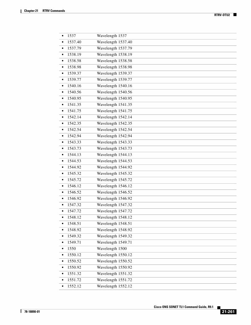
Chapter 21 RTRV CommandsRTRV-OTU2
• 1537 Wavelength 1537
• 1537.40 Wavelength 1537.40
• 1537.79 Wavelength 1537.79
• 1538.19 Wavelength 1538.19
• 1538.58 Wavelength 1538.58
• 1538.98 Wavelength 1538.98
• 1539.37 Wavelength 1539.37
• 1539.77 Wavelength 1539.77
• 1540.16 Wavelength 1540.16
• 1540.56 Wavelength 1540.56
• 1540.95 Wavelength 1540.95
• 1541.35 Wavelength 1541.35
• 1541.75 Wavelength 1541.75
• 1542.14 Wavelength 1542.14
• 1542.35 Wavelength 1542.35
• 1542.54 Wavelength 1542.54
• 1542.94 Wavelength 1542.94
• 1543.33 Wavelength 1543.33
• 1543.73 Wavelength 1543.73
• 1544.13 Wavelength 1544.13
• 1544.53 Wavelength 1544.53
• 1544.92 Wavelength 1544.92
• 1545.32 Wavelength 1545.32
• 1545.72 Wavelength 1545.72
• 1546.12 Wavelength 1546.12
• 1546.52 Wavelength 1546.52
• 1546.92 Wavelength 1546.92
• 1547.32 Wavelength 1547.32
• 1547.72 Wavelength 1547.72
• 1548.12 Wavelength 1548.12
• 1548.51 Wavelength 1548.51
• 1548.92 Wavelength 1548.92
• 1549.32 Wavelength 1549.32
• 1549.71 Wavelength 1549.71
• 1550 Wavelength 1500
• 1550.12 Wavelength 1550.12
• 1550.52 Wavelength 1550.52
• 1550.92 Wavelength 1550.92
• 1551.32 Wavelength 1551.32
• 1551.72 Wavelength 1551.72
• 1552.12 Wavelength 1552.12
21-261Cisco ONS SONET TL1 Command Guide, R9.1
78-18890-01

Chapter 21 RTRV CommandsRTRV-OTU2
• 1552.52 Wavelength 1552.52
• 1552.93 Wavelength 1552.93
• 1553.33 Wavelength 1553.33
• 1553.73 Wavelength 1553.73
• 1554.13 Wavelength 1554.13
• 1554.13 Wavelength 1554.13
• 1554.94 Wavelength 1554.94
• 1555.34 Wavelength 1555.34
• 1555.75 Wavelength 1555.75
• 1556.15 Wavelength 1556.15
• 1556.55 Wavelength 1556.55
• 1556.96 Wavelength 1556.96
• 1557.36 Wavelength 1557.36
• 1557.77 Wavelength 1557.77
• 1558.17 Wavelength 1558.17
• 1558.58 Wavelength 1558.58
• 1558.98 Wavelength 1558.98
• 1559.39 Wavelength 1559.39
• 1559.79 Wavelength 1559.79
• 1560.20 Wavelength 1560.20
• 1560.61 Wavelength 1560.61
• 1561.01 Wavelength 1561.01
• 1561.42 Wavelength 1561.42
• 1561.83 Wavelength 1561.83
• 1570 Wavelength 1570
• 1570.83 Wavelength 1570.83
• 1571.24 Wavelength 1571.24
• 1571.65 Wavelength 1571.65
• 1572.06 Wavelength 1572.06
• 1572.48 Wavelength 1572.48
• 1572.89 Wavelength 1572.89
• 1573.30 Wavelength 1573.30
• 1573.71 Wavelength 1573.71
• 1574.13 Wavelength 1574.13
• 1574.54 Wavelength 1574.54
• 1574.95 Wavelength 1574.95
• 1575.37 Wavelength 1575.37
• 1575.78 Wavelength 1575.78
• 1576.20 Wavelength 1576.20
• 1576.61 Wavelength 1576.61
• 1577.03 Wavelength 1577.03
21-262Cisco ONS SONET TL1 Command Guide, R9.1
78-18890-01

Chapter 21 RTRV CommandsRTRV-OTU2
• 1577.44 Wavelength 1577.44
• 1577.86 Wavelength 1577.86
• 1578.27 Wavelength 1578.27
• 1578.69 Wavelength 1578.69
• 1579.10 Wavelength 1579.10
• 1579.52 Wavelength 1579.52
• 1579.93 Wavelength 1579.93
• 1580.35 Wavelength 1580.35
• 1580.77 Wavelength 1580.77
• 1581.18 Wavelength 1581.18
• 1581.60 Wavelength 1581.60
• 1582.02 Wavelength 1582.02
• 1582.44 Wavelength 1582.44
• 1582.85 Wavelength 1582.85
• 1583.27 Wavelength 1583.27
• 1583.69 Wavelength 1583.69
• 1584.11 Wavelength 1584.11
• 1584.53 Wavelength 1584.53
• 1584.95 Wavelength 1584.95
• 1585.36 Wavelength 1585.36
• 1585.78 Wavelength 1585.78
• 1586.20 Wavelength 1586.20
• 1586.62 Wavelength 1586.62
• 1587.04 Wavelength 1587.04
• 1587.46 Wavelength 1587.46
• 1587.88 Wavelength 1587.88
• 1588.30 Wavelength 1588.30
• 1588.73 Wavelength 1588.73
• 1589.15 Wavelength 1589.15
• 1589.57 Wavelength 1589.57
• 1589.99 Wavelength 1589.99
• 1590 Wavelength 1590
• 1590.41 Wavelength 1590.41
• 1590.83 Wavelength 1590.83
• 1591.26 Wavelength 1591.26
• 1591.68 Wavelength 1591.68
• 1592.10 Wavelength 1592.10
• 1592.52 Wavelength 1592.52
• 1592.95 Wavelength 1592.95
• 1593.37 Wavelength 1593.37
• 1593.79 Wavelength 1593.79
21-263Cisco ONS SONET TL1 Command Guide, R9.1
78-18890-01

Chapter 21 RTRV CommandsRTRV-OTU2
• 1594.22 Wavelength 1594.22
• 1594.64 Wavelength 1594.64
• 1595.06 Wavelength 1595.06
• 1595.49 Wavelength 1595.49
• 1596.34 Wavelength 1596.34
• 1596.76 Wavelength 1596.76
• 1597.19 Wavelength 1597.19
• 1597.62 Wavelength 1597.62
• 1598.04 Wavelength 1598.04
• 1598.47 Wavelength 1598.47
• 1598.89 Wavelength 1598.89
• 1599.32 Wavelength 1599.32
• 1599.75 Wavelength 1599.75
• 1600.06 Wavelength 1600.06
• 1601.03 Wavelength 1601.03
• 1601.46 Wavelength 1601.46
• 1601.88 Wavelength 1601.88
• 1602.31 Wavelength 1602.31
• 1602.74 Wavelength 1602.74
• 1603.17 Wavelength 1603.17
• 1603.60 Wavelength 1603.60
• 1604.03 Wavelength 1604.03
• 1610 Wavelength 1610
• USE-TWL1 Use Tunable Wavelength 1
<LOSSB> (Optional) The parameter type is REACH, which indicates the reach values.
• AUTOPROV Autoprovisioning
• CX Reach CX
• DX Reach DX
• HX Reach HX
• I1 Reach I1
• IR-1 Reach IR-1
• IR-2 Reach IR-2
• L1 Reach L1
• L2 Reach L2
• L3 Reach L3
• LR-1 Reach LR-1
• LR-2 Reach LR-2
• LR-3 Reach LR-3
• LX Reach LX
• S1 Reach S1
• S2 Reach S2
21-264Cisco ONS SONET TL1 Command Guide, R9.1
78-18890-01

Chapter 21 RTRV CommandsRTRV-PATH-OCH
21.86 RTRV-PATH-OCH(ONS 15454) The Retrieve Path Optical Channel (RTRV-PATH-OCH) command retrieves the OCH path inside a node. An OCH path is a list of access identifiers that addresses all the possible facility and internal optical channels that are all associated to the same wavelength.
Usage Guidelines None
• SR Reach SR
• SR-1 Reach SR-1
• SX Reach SX
• T Reach T
• VX Reach VX
• ZX Reach ZX
<PORTNAME> (Optional) Port name. PORTNAME is a string.
<CMDMDE> (Optional) Command mode. Normal (NORM) mode is the default behavior for all commands but you can specify forced (FRCD) mode to force the system to override a state where the command would normally be denied. The FRCD mode of operation is applicable to delete a virtual concatenated (VCAT) member cross-connect in Unlocked-Enabled or Locked-Disabled, AutomaticInService service states.
<PST_PSTQ> Primary state. The parameter type is PST_PSTQ, which is the service state of the entity described by the PST and PSTQ.
• Unlocked-Enabled
In service and normal
• Unlocked-Disabled
Out of service and autonomous
• Locked-Disabled Out of service, autonomous and management
• Locked-Enabled Out of service and management
<SSTQ> (Optional) Secondary state. The parameter type is SST, which provides additional information pertaining to PST and PSTQ.
• AutomaticInService
Automatic in service
• Disabled Disabled
• Loopback Loopback
• MismatchofEquipmentAlarm
Mismatch of equipment and attributes
• Maintenance Maintenance mode
• OutOfGroup Out of group
• SoftwareDownload
Software downloading
• Unassigned Unassigned
• NotInstalled Unequipped
21-265Cisco ONS SONET TL1 Command Guide, R9.1
78-18890-01

Chapter 21 RTRV CommandsRTRV-PATH-OCH
Category DWDM
Security Retrieve
Input Format RTRV-PATH-OCH:[<TID>]:<AID>:<CTAG>[::::];
Input Example RTRV-PATH-OCH:PENNGROVE:CHAN-6-2:236;
Input Parameters
Output Format SID DATE TIMEM CTAG COMPLD "<AID>::[WLEN=<WLEN>],[PATH=<PATH>]:";
Output Example TID-000 1998-06-20 14:30:00M 001 COMPLD "CHAN-6-2::WLEN=1530.33,PATH=LINEWL-1-3-RX-1530.33&LINEWL-1-1-TX-1530.33&LINEWL-3-1-RX-1530.33&CHAN-3-1-TX&CHAN-6-2:";
Output Parameters
<AID> Access identifier from the “26.8 CHANNEL” section on page 19, “26.18 LINEWL” section on page 41, and “26.5 BANDWL” section on page 18.
<AID> Access identifier from the “26.8 CHANNEL” section on page 19, “26.18 LINEWL” section on page 41, and “26.5 BANDWL” section on page 18.
<WLEN> Defines the optical wavelength. The parameter type is OPTICAL_WLEN (optical wavelength).
• 1530.33 Wavelength C Band - 1/40
• 1530.72 Wavelength 1530.72
• 1531.12 Wavelength C Band - 2/40
• 1531.90 Wavelength C Band - 3/40
• 1532.68 Wavelength C Band - 4/40
• 1534.25 Wavelength C Band - 6/40
• 1535.04 Wavelength C Band - 7/40
• 1535.82 Wavelength C Band - 8/40
• 1536.61 Wavelength C Band - 9/40
• 1538.19 Wavelength C Band - 11/40
• 1538.98 Wavelength C Band - 12/40
21-266Cisco ONS SONET TL1 Command Guide, R9.1
78-18890-01

Chapter 21 RTRV CommandsRTRV-PATH-OCH
• 1539.77 Wavelength C Band - 13/40
• 1540.56 Wavelength C Band - 14/40
• 1542.14 Wavelength C Band - 16/40
• 1542.94 Wavelength C Band - 17/40
• 1543.73 Wavelength C Band - 18/40
• 1544.53 Wavelength C Band - 19/40
• 1546.12 Wavelength C Band - 21/40
• 1546.92 Wavelength C Band - 22/40
• 1547.72 Wavelength C Band - 23/40
• 1548.11 Wavelength 1548.11
• 1548.51 Wavelength C Band - 24/40
• 1548.91 Wavelength 1548.91
• 1549.72 Wavelength 1549.72
• 1550.12 Wavelength C Band - 26/40
• 1550.92 Wavelength C Band - 27/40
• 1551.72 Wavelength C Band - 28/40
• 1552.52 Wavelength C Band - 29/40
• 1554.13 Wavelength C Band - 31/40
• 1554.94 Wavelength C Band - 32/40
• 1555.75 Wavelength C Band - 33/40
• 1556.55 Wavelength C Band - 34/40
• 1558.17 Wavelength C Band - 36/40
• 1558.98 Wavelength C Band - 37/40
• 1559.79 Wavelength C Band - 38/40
• 1560.61 Wavelength C Band - 39/40
• 1577.44 L-Band Wavelength 1577.44
• 1577.86 L-Band Wavelength 1577.86
• 1578.27 L-Band Wavelength 1578.27
• 1578.69 L-Band Wavelength 1578.69
• 1579.10 L-Band Wavelength 1579.10
• 1579.52 L-Band Wavelength 1579.52
• 1579.93 L-Band Wavelength 1579.93
• 1580.35 L-Band Wavelength 1580.35
• 1580.77 L-Band Wavelength 1580.77
• 1581.18 L-Band Wavelength 1581.18
• 1581.60 L-Band Wavelength 1581.60
• 1582.02 L-Band Wavelength 1582.02
• 1582.44 L-Band Wavelength 1582.44
• 1582.85 L-Band Wavelength 1582.85
• 1583.27 L-Band Wavelength 1583.27
• 1583.69 L-Band Wavelength 1583.69
21-267Cisco ONS SONET TL1 Command Guide, R9.1
78-18890-01

Chapter 21 RTRV CommandsRTRV-PM-<MOD2>
21.87 RTRV-PM-<MOD2>(Cisco ONS 15454, 15327, 15600, 15310) The Retrieve Performance for 10GFC, 10GIGE, 40GIGE, 1GFC, 1GFICON, 2GFC, 2GFICON, 5GIB, 8GFC, CLNT, D1VIDEO, DS1, DV6000, DVBASI, E1, E3, E4, EC1, ESCON, ETH, ETRCLO, FSTE, G1000, GFPOS, GIGE, HDTV, ISC1, ILK, ISCCOMPAT, ISC3PEER2R, ISC3PEER1G, ISC3PEER2G, OC12, OC192, OC3, OC48, OC768, OCH, OMS, OTS, OTU3, POS, STS1, STS12C, STS18C, STS192C, STS24C, STS36C, STS3C, STS48C, STS96C, STS6C, STS9C, T1, T3, VC12, VC3, VT1, or VT2 (RTRV-PM-<MOD2>) command retrieves the values of PM parameters for a specified card type.
Usage Guidelines • See Table 28-1 on page 1 for supported modifiers by platform.
• MONLEV is in the format of LEV-DIRN.
• The format of MONDAT is MM-DD, where MM (month of the year) ranges from 1 to 12 and DD (day of the month) ranges from 1 to 31.
• 1584.11 L-Band Wavelength 1584.11
• 1584.53 L-Band Wavelength 1584.53
• 1584.95 L-Band Wavelength 1584.95
• 1585.36 L-Band Wavelength 1585.36
• 1585.78 L-Band Wavelength 1585.78
• 1586.20 L-Band Wavelength 1586.20
• 1586.62 L-Band Wavelength 1586.62
• 1587.04 L-Band Wavelength 1587.04
• 1587.46 L-Band Wavelength 1587.46
• 1587.88 L-Band Wavelength 1587.88
• 1588.30 L-Band Wavelength 1588.30
• 1588.73 L-Band Wavelength 1588.73
• 1589.15 L-Band Wavelength 1589.15
• 1589.57 L-Band Wavelength 1589.57
• 1589.99 L-Band Wavelength 1589.99
• 1590.41 L-Band Wavelength 1590.41
• 1590.83 L-Band Wavelength 1590.83
• 1591.26 L-Band Wavelength 1591.26
• 1591.68 L-Band Wavelength 1591.68
• 1592.10 L-Band Wavelength 1592.10
• 1592.52 L-Band Wavelength 1592.52
• 1592.95 L-Band Wavelength 1592.95
• 1593.37 L-Band Wavelength 1593.37
• 1593.79 L-Band Wavelength 1593.79
<PATH> Access identifier from the “26.8 CHANNEL” section on page 19 or the “26.18 LINEWL” section on page 41.
21-268Cisco ONS SONET TL1 Command Guide, R9.1
78-18890-01

Chapter 21 RTRV CommandsRTRV-PM-<MOD2>
• The format for MONTM is HH-MM, where HH (hour of the day) ranges from 0 to 23 and MM (minute of the hour) ranges from 0 to 59.
• If there are no errors to report, the response will be COMPLD (completed).
• If the TMPER is 1-DAY, MONTM is not applicable (null), and is treated as null if MONTM is not null.
• A null value for MONLEV defaults to 1-UP.
• A null value for MONDAT defaults to the current date (MM-DD).
• A null value for MONTM defaults to the current time (HH-MM).
• Unless otherwise stated, DS-1 cards are the only cards that support both the RCV and TRMT directions. All other cards only support the RCV direction.
• After BLSR switching, the working path is switched out, the traffic goes through the protection path, and the IPPM can be retrieved from the protection STS path.
• If there is a STS PCA on the protection path, during the BLSR switching, the PCA path is preemptive; sending this command on the protection path after a BLSR switch, the command returns the PMs from the protection path, not from the PCA path.
• Some MOD2 entities; for example, OCH, CLNT, and Optical (OCn), support negative MONTYPE values. By default, this command defaults to 0–UP (return MONTYPEs where the MONVAL is 0 or higher). To retrieve the negative values, you must issue 0–DN in the MONLEV field. The rules are as follows:
– Client port only–Laser and SONET PMs are applicable and will appear. If the card payload is in SONET mode, then SONET PMs will appear, provided the MONLEV criteria is met.
– Trunk port Laser PMs are always available. Laser PMs are only for near end. If ITU-T G.709 is enabled, then the OTN PMs will appear. If ITU-T G.709 and FEC are enabled, then the FEC PMs will appear. If the card payload is in SONET mode, then SONET PMs will appear. All PM MONVALUEs should pass the MONLEV filter criteria.
• For DWDM cards, the MONLEV filter criteria will not support a floating point. It will be returned and interpreted as an integer.
• If the DS-1 mode of the DS3XM-12 card is FDL, the DS-1 path can retrieve FDL/T.403 FEND PM counts up to 32 15-minute intervals in the RTRV-PM-DS1 command.
• RTRV-PM-<MOD2> can also be used to retrieve the RMON-managed PM data.
Category Performance
Security Retrieve
Input Format RTRV-PM-<MOD2>:[<TID>]:<AID>:<CTAG>::[<MONTYPE>],[<MONLEV>],[<LOCN>],[<DIRECTION>],[<TMPER>],[<DATE>],[<TIME>];
Input Example RTRV-PM-T1:TID:FAC-2-1:123::CVL,10-UP,NEND,RCV,15-MIN,04-11,12-45;
21-269Cisco ONS SONET TL1 Command Guide, R9.1
78-18890-01

Chapter 21 RTRV CommandsRTRV-PM-<MOD2>
Input Parameters <AID> Access identifier from the “26.1 ALL” section on page 1. All of the STS, VT1, Facility, and DS1 AIDs are supported.
<MONTYPE> Monitored type. A null value defaults to all montypes applicable to the modifier. The parameter type is ALL_MONTYPE, which is the monitoring type list.
• AISSP Alarm Indication Signal Seconds—Path
• ALL All possible values
• BBE-PM OTN—Background Block Errors—Path Monitor Point
• BBE-SM OTN—Background Block Errors—Section Monitor Point
• BBER-PM OTN—Background Block Error Ratio—Path Monitor Point expressed as one tenth of a percentage
• BBER-SM OTN—Background Block Error Ratio—Section Monitor Point expressed as one tenth of a percentage
• BIEC FEC—Bit Errors Corrected
• BIT-EC The number of bit errors corrected by the FEC algorithm
• CGV 8B10B—Code Group Violations
• CSSP Controlled Slip Seconds—Path (DSXM-12 FDL/T1.403 PM count)
• CVCPP Coding Violations—CP-Bit Path
• CVL Coding Violations—Line
• CVP Coding Violations—Path
• CVS Coding Violations—Section
• CVV Coding Violations—Section
• DCG 8B10B—Data Code Groups
• ESAP Errored Second Type A-Path (DS3XM-12 DS1 PM count)
• ESBP Errored Second Type B-Path (DS3XM-12 DS1 PM count)
• ESCPP Errored Seconds—CP—Bit Path
• ESL Errored Seconds—Line
• ESNPFE Errored Second—Network Path (DS3XM-12 DS1 PM count)
• ESP Errored Seconds—Path
• ES-PM OTN—Errored Seconds—Path Monitor Point
• ES-SM OTN—Errored Seconds—Section Monitor Point
• ESR Errored Second—Ratio
• ESR-PM Errored Seconds Ratio—Path monitor Point expressed as one tenth of a percentage
• ESR-SM Errored Seconds Ratio—Section monitor Point expressed as one tenth of a percentage
• ESS Errored Seconds—Section
• ESV Errored Seconds—VT Path
• dot3StatsFCSErrors A count of frames received on a particular interface that are an integral number of octets in length but do not pass the FCS check.
• dot3StatsFrameTooLong A count of frames received on a particular interface that exceed the maximum permitted frame size.
21-270Cisco ONS SONET TL1 Command Guide, R9.1
78-18890-01
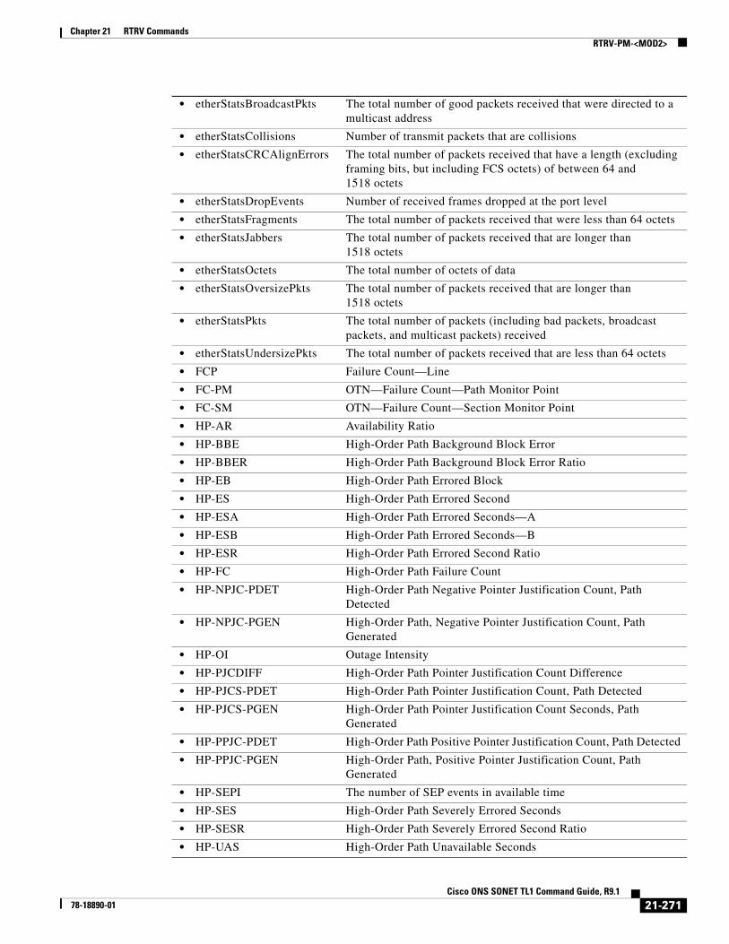
Chapter 21 RTRV CommandsRTRV-PM-<MOD2>
• etherStatsBroadcastPkts The total number of good packets received that were directed to a multicast address
• etherStatsCollisions Number of transmit packets that are collisions
• etherStatsCRCAlignErrors The total number of packets received that have a length (excluding framing bits, but including FCS octets) of between 64 and 1518 octets
• etherStatsDropEvents Number of received frames dropped at the port level
• etherStatsFragments The total number of packets received that were less than 64 octets
• etherStatsJabbers The total number of packets received that are longer than 1518 octets
• etherStatsOctets The total number of octets of data
• etherStatsOversizePkts The total number of packets received that are longer than 1518 octets
• etherStatsPkts The total number of packets (including bad packets, broadcast packets, and multicast packets) received
• etherStatsUndersizePkts The total number of packets received that are less than 64 octets
• FCP Failure Count—Line
• FC-PM OTN—Failure Count—Path Monitor Point
• FC-SM OTN—Failure Count—Section Monitor Point
• HP-AR Availability Ratio
• HP-BBE High-Order Path Background Block Error
• HP-BBER High-Order Path Background Block Error Ratio
• HP-EB High-Order Path Errored Block
• HP-ES High-Order Path Errored Second
• HP-ESA High-Order Path Errored Seconds—A
• HP-ESB High-Order Path Errored Seconds—B
• HP-ESR High-Order Path Errored Second Ratio
• HP-FC High-Order Path Failure Count
• HP-NPJC-PDET High-Order Path Negative Pointer Justification Count, Path Detected
• HP-NPJC-PGEN High-Order Path, Negative Pointer Justification Count, Path Generated
• HP-OI Outage Intensity
• HP-PJCDIFF High-Order Path Pointer Justification Count Difference
• HP-PJCS-PDET High-Order Path Pointer Justification Count, Path Detected
• HP-PJCS-PGEN High-Order Path Pointer Justification Count Seconds, Path Generated
• HP-PPJC-PDET High-Order Path Positive Pointer Justification Count, Path Detected
• HP-PPJC-PGEN High-Order Path, Positive Pointer Justification Count, Path Generated
• HP-SEPI The number of SEP events in available time
• HP-SES High-Order Path Severely Errored Seconds
• HP-SESR High-Order Path Severely Errored Second Ratio
• HP-UAS High-Order Path Unavailable Seconds
21-271Cisco ONS SONET TL1 Command Guide, R9.1
78-18890-01
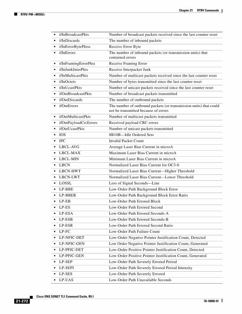
Chapter 21 RTRV CommandsRTRV-PM-<MOD2>
• ifInBroadcastPkts Number of broadcast packets received since the last counter reset
• ifInDiscards The number of inbound packets
• ifInErrorBytePktss Receive Error Byte
• ifInErrors The number of inbound packets (or transmission units) that contained errors
• ifInFramingErrorPkts Receive Framing Error
• ifInJunkInterPkts Receive Interpacket Junk
• ifInMulticastPkts Number of multicast packets received since the last counter reset
• ifInOctets Number of bytes transmitted since the last counter reset
• ifInUcastPkts Number of unicast packets received since the last counter reset
• ifOutBroadcastPkts Number of broadcast packets transmitted
• ifOutDiscards The number of outbound packets
• ifOutErrors The number of outbound packets (or transmission units) that could not be transmitted because of errors
• ifOutMulticastPkts Number of multicast packets transmitted
• ifOutPayloadCrcErrors Received payload CRC errors
• ifOutUcastPkts Number of unicast packets transmitted
• IOS 8B10B—Idle Ordered Sets
• IPC Invalid Packet Count
• LBCL-AVG Average Laser Bias Current in microA
• LBCL-MAX Maximum Laser Bias Current in microA
• LBCL-MIN Minimum Laser Bias Current in microA
• LBCN Normalized Laser Bias Current for OC3-8
• LBCN-HWT Normalized Laser Bias Current—Higher Threshold
• LBCN-LWT Normalized Laser Bias Current—Lower Threshold
• LOSSL Loss of Signal Seconds—Line
• LP-BBE Low-Order Path Background Block Error
• LP-BBER Low-Order Path Background Block Error Ratio
• LP-EB Low-Order Path Errored Block
• LP-ES Low-Order Path Errored Second
• LP-ESA Low-Order Path Errored Seconds-A
• LP-ESB Low-Order Path Errored Seconds-B
• LP-ESR Low-Order Path Errored Second Ratio
• LP-FC Low-Order Path Failure Count
• LP-NPJC-DET Low-Order Negative Pointer Justification Count, Detected
• LP-NPJC-GEN Low Order Negative Pointer Justification Count, Generated
• LP-PPJC-DET Low-Order Positive Pointer Justification Count, Detected
• LP-PPJC-GEN Low-Order Positive Pointer Justification Count, Generated
• LP-SEP Low-Order Path Severely Errored Period
• LP-SEPI Low-Order Path Severely Errored Period Intensity
• LP-SES Low-Order Path Severely Errored
• LP-UAS Low-Order Path Unavailable Seconds
21-272Cisco ONS SONET TL1 Command Guide, R9.1
78-18890-01

Chapter 21 RTRV CommandsRTRV-PM-<MOD2>
• MS-PSC Protection switch count
• MS-PSD Protection switch duration
• NIOS 8B10B—Non Idle Ordered Sets
• NPJC-PDET Negative Pointer Justification Count, Path Detected
• NPJC-PGEN Negative Pointer Justification Count, Path Generated
• OPR-AVG Average Receive Power in one tenth of a microwatt
• OPR-MAX Maximum Receive Power in one tenth of a microwatt
• OPR-MIN Minimum Receive Power in one tenth of a microwatt
• OPRN Normalized Optical Receive Power for OC3-8
• OPRN-MAX Maximum value for OPRN
• OPRN-MIN Minimum value for OPRN
• OPT-AVG Average Transmit Power in one tenth of a microwatt
• OPT-MAX Maximum Transmit Power in one tenth of a microwatt
• OPT-MIN Minimum Transmit Power in one tenth of a microwatt
• OPTN Normalized value for Optical Power Transmitted for the OC3-8 card
• OPTN-MAX Maximum value for OPTN
• OPTN-MIN Minimum value for OPTN
• OPWR-AVG Optical Power—Average Interval Value in one tenth of a dBm
• OPWR-MAX Optical Power—Maximum Interval Value in one tenth of a dBm
• OPWR-MIN Optical Power—Minimum Interval Value in one tenth of a dBm
• PPJC-PDET Positive Pointer Justification Count, Path Detected
• PPJC-PGEN Positive Pointer Justification Count, Path Generated
• PSC Protection Switching Count
• PSC-R Protection Switching Count—Ring
• PSC-S Protection Switching Count—Span
• PSC-W Protection Switching Count—Working
• PSD Protection Switching Duration
• PSD-R Protection Switching Duration—Ring
• PSD-S Protection Switching Duration—Span
• PSD-W Protection Switching Duration—Working
• SASCPP Severely Errored Framing/AIS Second—CP-Bit Path
• SASP Severely Errored Framing/AIS Seconds Path
• SEFS Severely Errored Framing Seconds
• SEFSP Severely Errored Framing Seconds—Path (DS3XM-12 DS1 PM count)
• SESCPP Severely Errored Second—CP-Bit Path
• SESL Severely Errored Second—Line
• SESNPFE Severely Errored Second—Network Path (DS3XM-12 DS1 PM count)
• SESP Severely Errored Second—Path
• SES-PM OTN—Severely Errored Second—Path
21-273Cisco ONS SONET TL1 Command Guide, R9.1
78-18890-01

Chapter 21 RTRV CommandsRTRV-PM-<MOD2>
• SESR-PM OTN—Severely Errored Second Ratio—Path Monitor Point expressed as one tenth of a percentage
• SESR-SM OTN—Severely Errored Second Ratio—Section Monitor Point expressed as one tenth of a percentage
• SESS Severely Errored Second—Section
• SES-SM OTN—Severely Errored Second—Section Monitor Point
• SESV Severely Errored Second—VT Path
• UASCPP Unavailable Second—CP-Bit Path
• UASL Unavailable Second—Line
• UASNPFE Unavailable Second—Network Path (DS3XM-12 DS1 PM count)
• UASP Unavailable Second—Path
• UAS-PM OTN—Unavailable Second—Path Monitor Point
• UAS-SM OTN—Unavailable Second—Section Monitor Point
• UASV Unavailable Second—VT Path
• UNC-WORDS FEC—Uncorrectable Words
• VPC Valid Packet Count
<MONLEV> The discriminating level of the requested monitored parameter in the format of LEVEL-DIRN, where LEVEL is the measured value of the monitored parameter (MONVAL) and DIRN is the type of direction. A null value defaults to 1-UP. MONLEV is a string.
<LOCN> Location associated with a particular command in reference to the entity identified by the AID. A null value defaults to NEND. The parameter type is LOCATION, which is the location where the action is to take place.
• FEND Action occurs on the far end of the facility
• NEND Action occurs on the near end of the facility
<DIRECTION> Type of direction. The parameter type is DIRECTION (transmit and receive directions).
• RCV Receive direction only.
• TRMT Transmit direction only.
<TMPER> Accumulation time period for performance counters. If TMPER is 1-DAY, MONTM is not applicable (null), and is treated as null. A null value defaults to 15-MIN. The parameter type is TMPER, which is the accumulation time period for the performance management center.
• 1-DAY Performance parameter accumulation interval length; every 24-hours. For SONET PM data, only one day of history data is available. For RMON managed PM data, seven days of history data are available.
• 1-HR Performance parameter accumulation interval length; every 1 hour. This is only applicable to RMON managed PM data. There are 24 hours of history data available.
• 1-MIN Performance parameter accumulation interval length; every 1 minute. This is only applicable to RMON managed PM data. There are 60 minutes of history available.
21-274Cisco ONS SONET TL1 Command Guide, R9.1
78-18890-01

Chapter 21 RTRV CommandsRTRV-PM-<MOD2>
Output Format SID DATE TIMEM CTAG COMPLD “<AID>,[<AIDTYPE>]:<MONTYPE>,<MONVAL>,[<VLDTY>],[<LOCN>], [<DIRECTION>],[<TMPER>],[<MONDAT>],[<MONTM>]”;
Output Example TID-000 1998-06-20 14:30:00M 001 COMPLD “FAC-2-1,DS1-14:CVL,21,COMPL,NEND,RCV,15-MIN,04-11,12-45”;
Output Parameters
• 15-MIN Performance parameter accumulation interval length; every 15 minutes. There are 32 15-MIN buckets of history data available for this accumulation interval length.
• RAW-DATA Performance parameter accumulation interval length; starting from the last time the counters were cleared. This is only applicable to RMON managed PMs.
<DATE> The beginning date of the PM or storage register period specified in TMPER. The format of DATE is MM-DD, where MM (month of year) ranges from 1 to 12 and DD (day of month) ranges from 1 to 31. A null value defaults to current date.
<TIME> The beginning time of day of the PM or storage register period specified in TMPER. The format of TIME is HH-MM, where HH (hour of day) ranges from 0 to 23 and MM (minute of hour) ranges from 0 to 59. A null value defaults to current time.
<AID> Access identifier from the “26.1 ALL” section on page 1.
<AIDTYPE> (Optional) Type of facility, link, or other addressable entity targeted by the message. The parameter type is MOD2B, which is the alarm type.
• 1GFC 1-Gigabit Fibre Channel payload
• 1GFICON 1-Gigabit fiber connectivity payload
• 2GFC 2-Gigabit Fibre Channel payload
• 2GFICON 2-Gigabit fiber connectivity payload
• 4GFC 4-Gigabit Fibre Channel payload
• 4GFICON 4-Gigabit fiber connectivity payload
• 40-GIGE 40-Gigabit ethernet
• 5GIB 5Gbps InfiniBand payload
• 8GFC 8-Gigabit Fibre Channel payload
• BITS BITS alarm
• CLNT Client facility for MXP/TXP cards
• COM Common alarm
• DS1 DS1 alarm
• DS3I DS3I alarm
21-275Cisco ONS SONET TL1 Command Guide, R9.1
78-18890-01

Chapter 21 RTRV CommandsRTRV-PM-<MOD2>
• DVBASI Digital Video Broadband Asynchronous Serial Interface (DVBASI) payload
• E100 E100 alarm
• E1000 E1000 alarm
• EC1 EC1 alarm
• ENV ENV alarm
• EQPT EQPT alarm
• FSTE Fast Ethernet Port alarm
• G1000 G1000 alarm
• GIGE Gigabit Ethernet port alarm
• ISC1 InterSystem Channel, a protocol defined by IBM (ISC1) payload
• ISC3PEER1G 1 Gbps ISC3 Peer
• ISC3PEER2G 2 Gbps ISC3 Peer
• ISC3PEER2R 1 Gbps or 2 Gbps ISC3 peer used in transparent (2R) mode
• ISCCOMPAT 1 Gbps ISC1, ISC2, and ISC3 compatibility
• OC3 OC3 alarm
• OC12 OC12 alarm
• OC48 OC48 alarm
• OC192 OC192 alarm
• OC768 OC768 alarm
• OCH Optical channel
• OMS Optical Multiplex Section
• OTS Optical Transport Section
• OTU3 Optical Transport Unit Level 3
• POS POS port alarm
• STS1 STS1 alarm
• STS3C STS3c alarm
• STS6C STS6c alarm
• STS9C STS9c alarm
• STS18C STS18c alarm
• STS12C STS12c alarm
• STS24C STS24c alarm
• STS36C STS36c alarm
• STS48C STS48c alarm
• STS192C STS192c alarm
• SYNCN SYNCN alarm
• T1 T1 alarm
• T3 T3 alarm
• TCC TCC alarm
• VT1 VT1 alarm
• VT2 VT2 alarm
21-276Cisco ONS SONET TL1 Command Guide, R9.1
78-18890-01

Chapter 21 RTRV CommandsRTRV-PM-<MOD2>
<MONTYPE> Monitored type. The parameter type is ALL_MONTYPE, which is the monitoring type list.
• AISSP Alarm Indication Signal Seconds—Path
• ALL All possible values
• BBE-PM OTN—Background Block Errors—Path Monitor Point
• BBE-SM OTN—Background Block Errors—Section Monitor Point
• BBER-PM OTN—Background Block Error Ratio—Path Monitor Point expressed as one tenth of a percentage
• BBER-SM OTN—Background Block Error Ratio—Section Monitor Point expressed as one tenth of a percentage
• BIEC FEC—Bit Errors Corrected
• BIT-EC The number of bit errors corrected by the FEC algorithm
• CGV 8B10B—Code Group Violations
• CSSP Controlled Slip Seconds—Path (DSXM-12 FDL/T1.403 PM count)
• CVCPP Coding Violations—CP-Bit Path
• CVL Coding Violations—Line
• CVP Coding Violations—Path
• CVS Coding Violations—Section
• CVV Coding Violations—Section
• DCG 8B10B—Data Code Groups
• dot3StatsFCSErrors A count of frames received on a particular interface that are an integral number of octets in length but do not pass the FCS check.
• dot3StatsFrameTooLong A count of frames received on a particular interface that exceed the maximum permitted frame size.
• ESAP Errored Second Type A-Path (DS3XM-12 DS1 PM count)
• ESBP Errored Second Type B-Path (DS3XM-12 DS1 PM count)
• ESCPP Errored Seconds—CP—Bit Path
• ESL Errored Seconds—Line
• ESNPFE Errored Second—Network Path (DS3XM-12 DS1 PM count)
• ESP Errored Seconds—Path
• ES-PM OTN—Errored Seconds—Path Monitor Point
• ES-SM OTN—Errored Seconds—Section Monitor Point
• ESR Errored Second—Ratio
• ESR-PM Errored Seconds Ratio—Path monitor Point expressed as one tenth of a percentage
• ESR-SM Errored Seconds Ratio—Section monitor Point expressed as one tenth of a percentage
• ESS Errored Seconds—Section
• ESV Errored Seconds—VT Path
• etherStatsBroadcastPkts The total number of good packets received that were directed to a multicast address
• etherStatsCollisions Number of transmit packets that are collisions
21-277Cisco ONS SONET TL1 Command Guide, R9.1
78-18890-01

Chapter 21 RTRV CommandsRTRV-PM-<MOD2>
• etherStatsCRCAlignErrors The total number of packets received that have a length (excluding framing bits, but including FCS octets) of between 64 and 1518 octets
• etherStatsDropEvents Number of received frames dropped at the port level
• etherStatsFragments The total number of packets received that were less than 64 octets
• etherStatsJabbers The total number of packets received that are longer than 1518 octets
• etherStatsOctets The total number of octets of data
• etherStatsOversizePkts The total number of packets received that are longer than 1518 octets
• etherStatsPkts The total number of packets (including bad packets, broadcast packets, and multicast packets) received
• etherStatsUndersizePkts The total number of packets received that are less than 64 octets
• FCP Failure Count—Line
• FC-PM OTN—Failure Count—Path Monitor Point
• FC-SM OTN—Failure Count—Section Monitor Point
• HP-AR Availability Ratio
• HP-BBE High-Order Path Background Block Error
• HP-BBER High-Order Path Background Block Error Ratio
• HP-EB High-Order Path Errored Block
• HP-ES High-Order Path Errored Second
• HP-ESA High-Order Path Errored Seconds—A
• HP-ESB High-Order Path Errored Seconds—B
• HP-ESR High-Order Path Errored Second Ratio
• HP-FC High-Order Path Failure Count
• HP-NPJC-PDET High-Order Path Negative Pointer Justification Count, Path Detected
• HP-NPJC-PGEN High-Order Path, Negative Pointer Justification Count, Path Generated
• HP-OI Outage Intensity
• HP-PJCDIFF High-Order Path Pointer Justification Count Difference
• HP-PJCS-PDET High-Order Path Pointer Justification Count seconds, Path Detected
• HP-PJCS-PGEN High-Order Path Pointer Justification Count Seconds, Path Generated
• HP-PPJC-PDET High-Order Path Positive Pointer Justification Count, Path Detected
• HP-PPJC-PGEN High-Order Path, Positive Pointer Justification Count, Path Generated
• HP-SEPI The number of SEP events in available time
• HP-SES High-Order Path Severely Errored Seconds
• HP-SESR High-Order Path Severely Errored Second Ratio
• HP-UAS High-Order Path Unavailable Seconds
• ifInBroadcastPkts Number of broadcast packets received since the last counter reset
• ifInDiscards The number of inbound packets
21-278Cisco ONS SONET TL1 Command Guide, R9.1
78-18890-01

Chapter 21 RTRV CommandsRTRV-PM-<MOD2>
• ifInErrorBytePktss Receive Error Byte
• ifInErrors The number of inbound packets (or transmission units) that contained errors
• ifInFramingErrorPkts Receive Framing Error
• ifInJunkInterPkts Receive Interpacket Junk
• ifInMulticastPkts Number of multicast packets received since the last counter reset
• ifInOctets Number of bytes transmitted since the last counter reset
• ifInUcastPkts Number of unicast packets received since the last counter reset
• ifOutBroadcastPkts Number of broadcast packets transmitted
• ifOutDiscards The number of outbound packets
• ifOutErrors The number of outbound packets (or transmission units) that could not be transmitted because of errors
• ifOutMulticastPkts Number of multicast packets transmitted
• ifOutPayloadCrcErrors Received payload CRC errors
• ifOutUcastPkts Number of unicast packets transmitted
• IOS 8B10B—Idle Ordered Sets
• IPC Invalid Packet Count
• LBCL-AVG Average Laser Bias Current in microA
• LBCL-MAX Maximum Laser Bias Current in microA
• LBCL-MIN Minimum Laser Bias Current in microA
• LBCN Normalized Laser Bias Current for OC3-8
• LBCN-HWT Normalized Laser Bias Current—Higher Threshold
• LBCN-LWT Normalized Laser Bias Current—Lower Threshold
• LOSSL Loss of Signal Seconds—Line
• LP-BBE Low-Order Path Background Block Error
• LP-BBER Low-Order Path Background Block Error Ratio
• LP-EB Low-Order Path Errored Block
• LP-ES Low-Order Path Errored Second
• LP-ESA Low-Order Path Errored Seconds-A
• LP-ESB Low-Order Path Errored Seconds-B
• LP-ESR Low-Order Path Errored Second Ratio
• LP-FC Low-Order Path Failure Count
• LP-NPJC-DET Low-Order Negative Pointer Justification Count, Detected
• LP-NPJC-GEN Low Order Negative Pointer Justification Count, Generated
• LP-PPJC-DET Low-Order Positive Pointer Justification Count, Detected
• LP-PPJC-GEN Low-Order positive Pointer Justification Count, Generated
• LP-SEP Low-Order Path Severely Errored Period
• LP-SEPI Low-Order Path Severely Errored Period Intensity
• LP-SES Low-Order Path Severely Errored
• LP-UAS Low-Order Path Unavailable Seconds
• MS-PSC Protection switch count
• MS-PSD Protection switch duration
21-279Cisco ONS SONET TL1 Command Guide, R9.1
78-18890-01

Chapter 21 RTRV CommandsRTRV-PM-<MOD2>
• NIOS 8B10B—Non Idle Ordered Sets
• NPJC-PDET Negative Pointer Justification Count, Path Detected
• NPJC-PGEN Negative Pointer Justification Count, Path Generated
• OPR-AVG Average Receive Power in one tenth of a microwatt
• OPR-MAX Maximum Receive Power in one tenth of a microwatt
• OPR-MIN Minimum Receive Power in one tenth of a microwatt
• OPRN Normalized Optical Receive Power for OC3-8
• OPRN-MAX Maximum value for OPRN
• OPRN-MIN Minimum value for OPRN
• OPT-AVG Average Transmit Power in one tenth of a microwatt
• OPT-MAX Maximum Transmit Power in one tenth of a microwatt
• OPT-MIN Minimum Transmit Power in one tenth of a microwatt
• OPTN Normalized value for Optical Power Transmitted for the OC3-8 card
• OPTN-MAX Maximum value for OPTN
• OPTN-MIN Minimum value for OPTN
• OPWR-AVG Optical Power—Average Interval Value in one tenth of a dBm
• OPWR-MAX Optical Power—Maximum Interval Value in one tenth of a dBm
• OPWR-MIN Optical Power—Minimum Interval Value in one tenth of a dBm
• PPJC-PDET Positive Pointer Justification Count, Path Detected
• PPJC-PGEN Positive Pointer Justification Count, Path Generated
• PSC Protection Switching Count
• PSC-R Protection Switching Count—Ring
• PSC-S Protection Switching Count—Span
• PSC-W Protection Switching Count—Working
• PSD Protection Switching Duration
• PSD-R Protection Switching Duration—Ring
• PSD-S Protection Switching Duration—Span
• PSD-W Protection Switching Duration—Working
• SASCPP Severely Errored Framing/AIS Second—CP-Bit Path
• SASP Severely Errored Framing/AIS Seconds Path
• SEFS Severely Errored Framing Seconds
• SEFSP Severely Errored Framing Seconds—Path (DS3XM-12 DS1 PM count)
• SESCPP Severely Errored Second—CP-Bit Path
• SESL Severely Errored Second—Line
• SESNPFE Severely Errored Second—Network Path (DS3XM-12 DS1 PM count)
• SESP Severely Errored Second—Path
• SES-PM OTN—Severely Errored Second—Path
• SESR-PM OTN—Severely Errored Second Ratio—Path Monitor Point expressed as one tenth of a percentage
21-280Cisco ONS SONET TL1 Command Guide, R9.1
78-18890-01
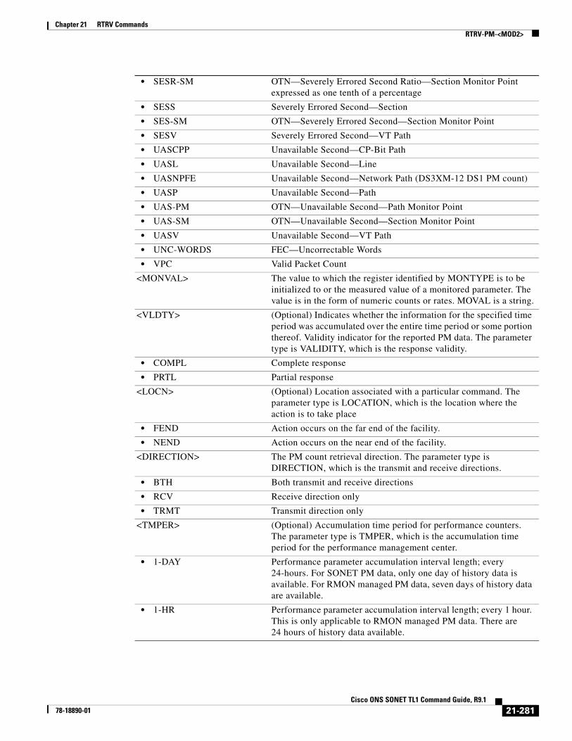
Chapter 21 RTRV CommandsRTRV-PM-<MOD2>
• SESR-SM OTN—Severely Errored Second Ratio—Section Monitor Point expressed as one tenth of a percentage
• SESS Severely Errored Second—Section
• SES-SM OTN—Severely Errored Second—Section Monitor Point
• SESV Severely Errored Second—VT Path
• UASCPP Unavailable Second—CP-Bit Path
• UASL Unavailable Second—Line
• UASNPFE Unavailable Second—Network Path (DS3XM-12 DS1 PM count)
• UASP Unavailable Second—Path
• UAS-PM OTN—Unavailable Second—Path Monitor Point
• UAS-SM OTN—Unavailable Second—Section Monitor Point
• UASV Unavailable Second—VT Path
• UNC-WORDS FEC—Uncorrectable Words
• VPC Valid Packet Count
<MONVAL> The value to which the register identified by MONTYPE is to be initialized to or the measured value of a monitored parameter. The value is in the form of numeric counts or rates. MOVAL is a string.
<VLDTY> (Optional) Indicates whether the information for the specified time period was accumulated over the entire time period or some portion thereof. Validity indicator for the reported PM data. The parameter type is VALIDITY, which is the response validity.
• COMPL Complete response
• PRTL Partial response
<LOCN> (Optional) Location associated with a particular command. The parameter type is LOCATION, which is the location where the action is to take place
• FEND Action occurs on the far end of the facility.
• NEND Action occurs on the near end of the facility.
<DIRECTION> The PM count retrieval direction. The parameter type is DIRECTION, which is the transmit and receive directions.
• BTH Both transmit and receive directions
• RCV Receive direction only
• TRMT Transmit direction only
<TMPER> (Optional) Accumulation time period for performance counters. The parameter type is TMPER, which is the accumulation time period for the performance management center.
• 1-DAY Performance parameter accumulation interval length; every 24-hours. For SONET PM data, only one day of history data is available. For RMON managed PM data, seven days of history data are available.
• 1-HR Performance parameter accumulation interval length; every 1 hour. This is only applicable to RMON managed PM data. There are 24 hours of history data available.
21-281Cisco ONS SONET TL1 Command Guide, R9.1
78-18890-01

Chapter 21 RTRV CommandsRTRV-PM-ALL
21.88 RTRV-PM-ALL(Cisco ONS 15454, 15327, 15600, 15310) The Retrieve Performance Monitoring All (RTRV-PM-ALL) command retrieves the values of all the performance monitoring parameters for the specified AID. When the ALL AID is used, the response will include the PM parameters for all cards and ports in the chassis.
Usage Guidelines • The format of MONLEV is LEV-DIRN.
• The format of MONDAT is MM-DD, where MM (month of the year) ranges from 1 to 12 and DD (day of the month) ranges from 1 to 31.
• The format for MONTM is HH-MM, where HH (hour of the day) ranges from 0 to 23 and MM (minute of the hour) ranges from 0 to 59.
• If the TMPER is 1-DAY, MONTM is not applicable (null), and is treated as null if MONTM is not null.
• A null value for MONLEV defaults to 1-UP.
• A null value for MONDAT defaults to the current date (MM-DD).
• A null value for MONTM defaults to the current time (HH-MM).
• Unless otherwise stated, DS-1 cards are the only cards that support both the RCV and TRMT directions. All other cards only support the RCV direction.
• After BLSR switching, the working path is switched out, the traffic goes through the protection path, and the IPPM can be retrieved from the protection STS path.
• If there is a STS PCA on the protection path, during the BLSR switching, the PCA path is preemptive; sending this command on the protection path after a BLSR switch, the command returns the PMs from the protection path, not from the PCA path.
• 1-MIN Performance parameter accumulation interval length; every 1 minute. This is only applicable to RMON managed PM data. There are 60 minutes of history available.
• 15-MIN Performance parameter accumulation interval length; every 15 minutes. There are 32 15-MIN buckets of history data available for this accumulation interval length.
• RAW-DATA Performance parameter accumulation interval length; starting from the last time the counters were cleared. This is only applicable to RMON managed PMs.
<MONDAT> (Optional) The beginning date of the PM or storage register period specified in TMPER. The format of MONDAT is MM-DD, where MM (month of year) ranges from 1 to 12 and DD (day of month) ranges from 1 to 31. MONDAT is a string.
<MONTM> (Optional) The beginning time of day of the PM or storage register period specified in TMPER. The format of MONTM is HH-MM, where HH (hour of day) ranges from 0 to 23 and MM (minute of hour) ranges from 0 to 59. MONTM is a string.
21-282Cisco ONS SONET TL1 Command Guide, R9.1
78-18890-01

Chapter 21 RTRV CommandsRTRV-PM-ALL
• Some MOD2 entities; for example, OCH, CLNT, and Optical (OCn), support negative MONTYPE values. By default, this command defaults to 0–UP (return MONTYPEs where the MONVAL is 0 or higher). To retrieve the negative values, you must issue 0–DN in the MONLEV field. The rules are as follows:
– Client port only–Laser and SONET PMs are applicable and will appear. If the card payload is in SONET mode, then SONET PMs will appear, provided the MONLEV criteria is met.
– Trunk port Laser PMs are always available. Laser PMs are only for near end. If ITU-T G.709 is enabled, then the OTN PMs will appear. If ITU-T G.709 and FEC are enabled, then the FEC PMs will appear. If the card payload is in SONET mode, then SONET PMs will appear. All PM MONVALUEs should pass the MONLEV filter criteria.
• For DWDM cards, the MONLEV filter criteria will not support a floating point. It will be returned and interpreted as an integer.
• If the DS-1 mode of the DS3XM-12 card is FDL, the DS-1 path can retrieve FDL/T.403 FEND PM counts up to 32 15-minute intervals in the RTRV-PM-DS1 command.
• BTH is not supported for the direction. A null value for direction should take care of TRMT and RCV.
• RTRV-PM-ALL command can also be used to retrieve the RMON managed PM data.
Category Performance
Security Retrieve
Input Format RTRV-PM-ALL:[<TID>]:<AID>:<CTAG>::[<MONTYPE>],[<MONLEV>],[<LOCN>],[<DIRECTION>],[<TMPER>],[<DATE>],[<TIME>];
Input Example RTRV-PM-ALL:TID:FAC-2-1:123::CVL,10-UP,NEND,RCV,15-MIN,04-11,12-45;
Input Parameters <AID> The DS1 AID is used access DS1 frame layer of the DS3XM. Format is DS1-[SLOT]-[DS3PORT]-[DS1PORT].
• 1GFC 1-Gigabit Fibre Channel payload
• 1GFICON 1-Gigabit fiber connectivity payload
• 2GFC 2-Gigabit Fibre Channel payload
• 2GFICON 2-Gigabit fiber connectivity payload
• CLNT Client facility
• DS1 DS1 line of a DS3XM card
• DS3I DS3I line
• DV6000 DV6000
• EC1 EC1 facility
• ESCON ESCON
• ETRCLO ETR_CLO
21-283Cisco ONS SONET TL1 Command Guide, R9.1
78-18890-01

Chapter 21 RTRV CommandsRTRV-PM-ALL
• FSTE FSTE facility
• G1000 G1000 facility
• GFPOS GFP over POS. Virtual ports partitioned using GFP’s multiplexing capability.
• GIGE Gigabit Ethernet
• HDTV HDTV
• ISC3PEER1G 1 Gbps ISC3 Peer
• ISC3PEER2G 2 Gbps ISC3 Peer
• ISC3PEER2R 1 Gbps or 2 Gbps ISC3 peer used in transparent (2R) mode
• ISCCOMPAT 1 Gbps ISC1, ISC2, and ISC3 compatibility
• OC3 OC3 facility
• OC12 OC12 facility
• OC48 OC48 facility
• OC192 OC192 facility
• OCH Optical channel
• OCHCC OCH client connection
• OCHNC OCH network connection
• OCHTERM OCH termination
• OMS Optical Multiplex Section
• OTS Optical Transport Section
• POS POS port
• STS1 STS1 path
• STS3C STS3c path
• STS6C STS6c path
• STS9C STS9c path
• STS18C STS18c path
• STS12C STS12c path
• STS24C STS24c path
• STS36C STS36c path
• STS48C STS48c path
• STS192C STS192c path
• T1 T1/DS1 facility/line
• T3 T3/DS1 facility/line
• VT1 VT1 path
• VT2 VT2 path
<MONTYPE> Monitoring type. A null value defaults to all montypes applicable to the modifier. The parameter type is ALL_MONTYPE, which is the monitoring type list.
• AISSP Alarm Indication Signal Seconds—Path
• ALL All possible values
• BBE-PM OTN—Background Block Errors—Path Monitor Point
• BBE-SM OTN—Background Block Errors—Section Monitor Point
21-284Cisco ONS SONET TL1 Command Guide, R9.1
78-18890-01

Chapter 21 RTRV CommandsRTRV-PM-ALL
• BBER-PM OTN—Background Block Error Ratio—Path Monitor Point expressed as one tenth of a percentage
• BBER-SM OTN—Background Block Error Ratio—Section Monitor Point expressed as one tenth of a percentage
• BIEC FEC—Bit Errors Corrected
• BIT-EC The number of bit errors corrected by the FEC algorithm
• CGV 8B10B—Code Group Violations
• CSSP Controlled Slip Seconds—Path (DSXM-12 FDL/T1.403 PM count)
• CVCPP Coding Violations—CP-Bit Path
• CVL Coding Violations—Line
• CVP Coding Violations—Path
• CVS Coding Violations—Section
• CVV Coding Violations—Section
• DCG 8B10B—Data Code Groups
• ESAP Errored Second Type A-Path (DS3XM-12 DS1 PM count)
• ESBP Errored Second Type B-Path (DS3XM-12 DS1 PM count)
• ESCPP Errored Seconds—CP—Bit Path
• ESL Errored Seconds—Line
• ESNPFE Errored Second—Network Path (DS3XM-12 DS1 PM count)
• ESP Errored Seconds—Path
• ES-PM OTN—Errored Seconds—Path Monitor Point
• ES-SM OTN—Errored Seconds—Section Monitor Point
• ESR Errored Second—Ratio
• ESR-PM Errored Seconds Ratio—Path monitor point expressed as one tenth of a percentage
• ESR-SM Errored Seconds Ratio—Section monitor point expressed as one tenth of a percentage
• ESS Errored Seconds—Section
• ESV Errored Seconds—VT Path
• etherStatsBroadcastPkts The total number of good packets received that were directed to a multicast address
• etherStatsCollisions Number of transmit packets that are collisions
• etherStatsCRCAlignErrors The total number of packets received that have a length (excluding framing bits, but including FCS octets) of between 64 and 1518 octets
• etherStatsDropEvents Number of received frames dropped at the port level
• etherStatsFragments The total number of packets received that were less than 64 octets
• etherStatsJabbers The total number of packets received that are longer than 1518 octets
• etherStatsOctets The total number of octets of data
• etherStatsOversizePkts The total number of packets received that are longer than 1518 octets
• etherStatsPkts The total number of packets (including bad packets, broadcast packets, and multicast packets) received
• etherStatsUndersizePkts The total number of packets received that are less than 64 octets
• FCP Failure Count—Line
21-285Cisco ONS SONET TL1 Command Guide, R9.1
78-18890-01

Chapter 21 RTRV CommandsRTRV-PM-ALL
• FC-PM OTN—Failure Count—Path Monitor Point
• FC-SM OTN—Failure Count—Section Monitor Point
• HP-AR Availability Ratio
• HP-BBE High-Order Path Background Block Error
• HP-BBER High-Order Path Background Block Error Ratio
• HP-EB High-Order Path Errored Block
• HP-ES High-Order Path Errored Second
• HP-ESA High-Order Path Errored Seconds—A
• HP-ESB High-Order Path Errored Seconds—B
• HP-ESR High-Order Path Errored Second Ratio
• HP-FC High-Order Path Failure Count
• HP-NPJC-PDET High-Order Path Negative Pointer Justification Count, Path Detected
• HP-NPJC-PGEN High-Order Path Negative Pointer Justification Count, Path Generated
• HP-OI High-Order Path, Outage Intensity
• HP-PJCDIFF High-Order Path Pointer Justification Count Difference
• HP-PJCS-PDET High-Order Path Pointer Justification Count Seconds, Path Detected
• HP-PJCS-PGEN High-Order Path Pointer Justification Count Seconds, Path Generated
• HP-PPJC-PDET High-Order Path Positive Pointer Justification Count, Path Detected
• HP-PPJC-PGEN High-Order Path, Positive Pointer Justification Count, Path Generated
• HP-SEPI The number of SEP events in available time
• HP-SES High-Order Path Severely Errored Seconds
• HP-SESR High-Order Path Severely Errored Second Ratio
• HP-UAS High-Order Path Unavailable Seconds
• ifInBroadcastPkts Number of broadcast packets received since the last counter reset
• ifInDiscards The number of inbound packets
• ifInErrorBytePktss Receive Error Byte
• ifInErrors The number of inbound packets (or transmission units) that contained errors
• ifInFramingErrorPkts Receive Framing Error
• ifInJunkInterPkts Receive Interpacket Junk
• ifInMulticastPkts Number of multicast packets received since the last counter reset
• ifInOctets Number of bytes transmitted since the last counter reset
• ifInUcastPkts Number of unicast packets received since the last counter reset
• ifOutBroadcastPkts Number of broadcast packets transmitted
• ifOutDiscards The number of outbound packets
• ifOutErrors The number of outbound packets (or transmission units) that could not be transmitted because of errors
• ifOutMulticastPkts Number of multicast packets transmitted
• ifOutPayloadCrcErrors Received payload CRC errors
• ifOutUcastPkts Number of unicast packets transmitted
• IOS 8B10B—Idle Ordered Sets
• IPC Invalid Packet Count
21-286Cisco ONS SONET TL1 Command Guide, R9.1
78-18890-01

Chapter 21 RTRV CommandsRTRV-PM-ALL
• LBCL-AVG Average Laser Bias Current in microA
• LBCL-MAX Maximum Laser Bias Current in microA
• LBCL-MIN Minimum Laser Bias Current in microA
• LBCN Normalized Laser Bias Current for OC3-8
• LBCN-HWT Normalized Laser Bias Current—Higher Threshold
• LBCN-LWT Normalized Laser Bias Current—Lower Threshold
• LOSSL Loss of Signal Seconds—Line
• LP-BBE Low-Order Path Background Block Error
• LP-BBER Low-Order Path Background Block Error Ratio
• LP-EB Low-Order Path Errored Block
• LP-ES Low-Order Path Errored Second
• LP-ESA Low-Order Path Errored Seconds-A
• LP-ESB Low-Order Path Errored Seconds-B
• LP-ESR Low-Order Path Errored Second Ratio
• LP-FC Low-Order Path Failure Count
• LP-NPJC-DET Low-Order Negative Pointer Justification Count, Detected
• LP-NPJC-GEN Low Order Negative Pointer Justification Count, Generated
• LP-PPJC-DET Low-Order Positive Pointer Justification Count, Detected
• LP-PPJC-GEN Low-Order positive Pointer Justification Count, Generated
• LP-SEP Low-Order Path Severely Errored Period
• LP-SEPI Low-Order Path Severely Errored Period Intensity
• LP-SES Low-Order Path Severely Errored
• LP-UAS Low-Order Path Unavailable Seconds
• MS-PSC Protection switch count
• MS-PSD Protection switch duration
• NIOS 8B10B—Non Idle Ordered Sets
• NPJC-PDET Negative Pointer Justification Count, Path Detected
• NPJC-PGEN Negative Pointer Justification Count, Path Generated
• OPR-AVG Average Receive Power in one tenth of a microwatt
• OPR-MAX Maximum Receive Power in one tenth of a microwatt
• OPR-MIN Minimum Receive Power in one tenth of a microwatt
• OPRN Normalized Optical Receive Power for OC3-8
• OPRN-MAX Maximum value for OPRN
• OPRN-MIN Minimum value for OPRN
• OPT-AVG Average Transmit Power in one tenth of a microwatt
• OPT-MAX Maximum Transmit Power in one tenth of a microwatt
• OPT-MIN Minimum Transmit Power in one tenth of a microwatt
• OPTN Normalized value for Optical Power Transmitted for the OC3-8 card
• OPTN-MAX Maximum value for OPTN
• OPTN-MIN Minimum value for OPTN
• OPWR-AVG Optical Power—Average Interval Value in one tenth of a dBm
21-287Cisco ONS SONET TL1 Command Guide, R9.1
78-18890-01
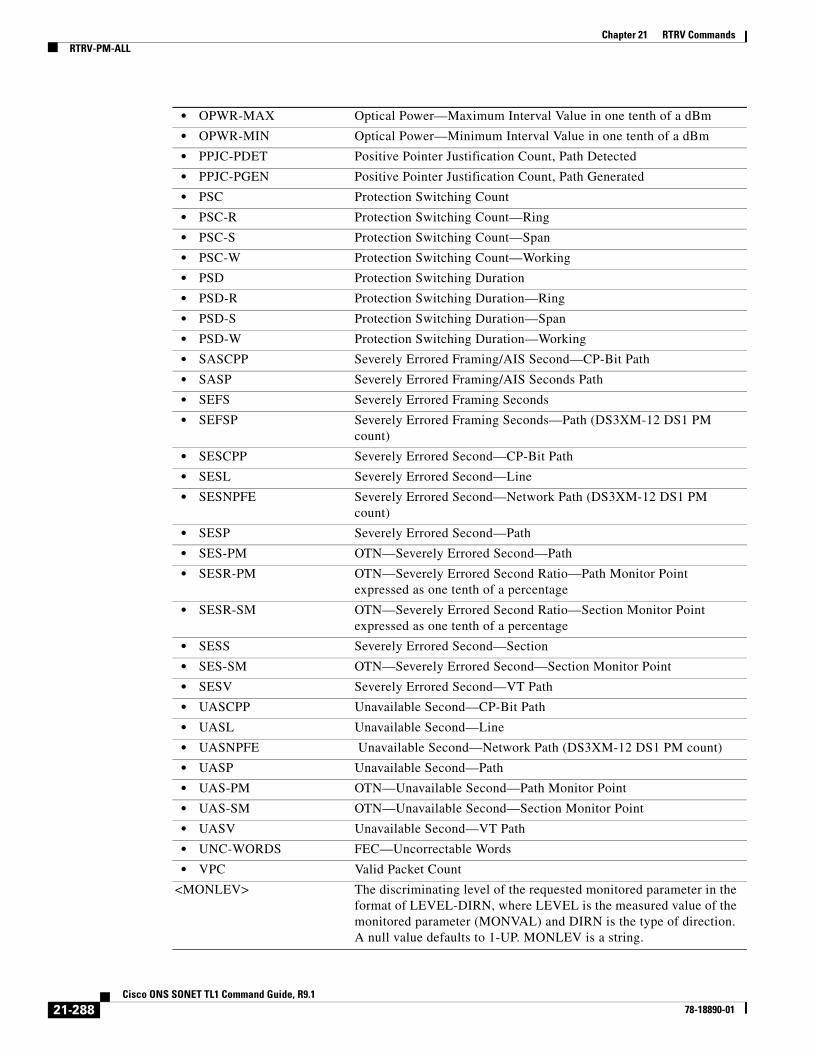
Chapter 21 RTRV CommandsRTRV-PM-ALL
• OPWR-MAX Optical Power—Maximum Interval Value in one tenth of a dBm
• OPWR-MIN Optical Power—Minimum Interval Value in one tenth of a dBm
• PPJC-PDET Positive Pointer Justification Count, Path Detected
• PPJC-PGEN Positive Pointer Justification Count, Path Generated
• PSC Protection Switching Count
• PSC-R Protection Switching Count—Ring
• PSC-S Protection Switching Count—Span
• PSC-W Protection Switching Count—Working
• PSD Protection Switching Duration
• PSD-R Protection Switching Duration—Ring
• PSD-S Protection Switching Duration—Span
• PSD-W Protection Switching Duration—Working
• SASCPP Severely Errored Framing/AIS Second—CP-Bit Path
• SASP Severely Errored Framing/AIS Seconds Path
• SEFS Severely Errored Framing Seconds
• SEFSP Severely Errored Framing Seconds—Path (DS3XM-12 DS1 PM count)
• SESCPP Severely Errored Second—CP-Bit Path
• SESL Severely Errored Second—Line
• SESNPFE Severely Errored Second—Network Path (DS3XM-12 DS1 PM count)
• SESP Severely Errored Second—Path
• SES-PM OTN—Severely Errored Second—Path
• SESR-PM OTN—Severely Errored Second Ratio—Path Monitor Point expressed as one tenth of a percentage
• SESR-SM OTN—Severely Errored Second Ratio—Section Monitor Point expressed as one tenth of a percentage
• SESS Severely Errored Second—Section
• SES-SM OTN—Severely Errored Second—Section Monitor Point
• SESV Severely Errored Second—VT Path
• UASCPP Unavailable Second—CP-Bit Path
• UASL Unavailable Second—Line
• UASNPFE Unavailable Second—Network Path (DS3XM-12 DS1 PM count)
• UASP Unavailable Second—Path
• UAS-PM OTN—Unavailable Second—Path Monitor Point
• UAS-SM OTN—Unavailable Second—Section Monitor Point
• UASV Unavailable Second—VT Path
• UNC-WORDS FEC—Uncorrectable Words
• VPC Valid Packet Count
<MONLEV> The discriminating level of the requested monitored parameter in the format of LEVEL-DIRN, where LEVEL is the measured value of the monitored parameter (MONVAL) and DIRN is the type of direction. A null value defaults to 1-UP. MONLEV is a string.
21-288Cisco ONS SONET TL1 Command Guide, R9.1
78-18890-01
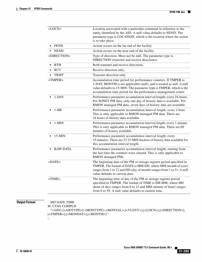
Chapter 21 RTRV CommandsRTRV-PM-ALL
Output Format SID DATE TIMEM CTAG COMPLD “<AID>,[<AIDTYPE>]:<MONTYPE>,<MONVAL>,[<VLDTY>],[<LOCN>],[<DIRECTION>],[<TMPER>],[<MONDAT>],[<MONTM>]”;
<LOCN> Location associated with a particular command in reference to the entity identified by the AID. A null value defaults to NEND. The parameter type is LOCATION, which is the location where the action is to take place.
• FEND Action occurs on the far end of the facility
• NEND Action occurs on the near end of the facility
<DIRECTION> Type of direction. Must not be null. The parameter type is DIRECTION (transmit and receive directions).
• BTH Both transmit and receive directions.
• RCV Receive direction only.
• TRMT Transmit direction only.
<TMPER> Accumulation time period for performance counters. If TMPER is 1-DAY, MONTM is not applicable (null), and is treated as null. A null value defaults to 15-MIN. The parameter type is TMPER, which is the accumulation time period for the performance management center.
• 1-DAY Performance parameter accumulation interval length; every 24-hours. For SONET PM data, only one day of history data is available. For RMON managed PM data, seven days of history data are available.
• 1-HR Performance parameter accumulation interval length; every 1 hour. This is only applicable to RMON managed PM data. There are 24 hours of history data available.
• 1-MIN Performance parameter accumulation interval length; every 1 minute. This is only applicable to RMON managed PM data. There are 60 minutes of history available.
• 15-MIN Performance parameter accumulation interval length; every 15 minutes. There are 32 15-MIN buckets of history data available for this accumulation interval length.
• RAW-DATA Performance parameter accumulation interval length; starting from the last time the counters were cleared. This is only applicable to RMON managed PMs.
<DATE> The beginning date of the PM or storage register period specified in TMPER. The format of DATE is MM-DD, where MM (month of year) ranges from 1 to 12 and DD (day of month) ranges from 1 to 31. A null value defaults to current date.
<TIME> The beginning time of day of the PM or storage register period specified in TMPER. The format of TIME is HH-MM, where HH (hour of day) ranges from 0 to 23 and MM (minute of hour) ranges from 0 to 59. A null value defaults to current time.
21-289Cisco ONS SONET TL1 Command Guide, R9.1
78-18890-01

Chapter 21 RTRV CommandsRTRV-PM-ALL
Output Example TID-000 1998-06-20 14:30:00M 001 COMPLD “FAC-2-1,DS1-14:CVL,21,COMPL,NEND,RCV,15-MIN,04-11,12-45”;
Output Parameters <AID> The DS1 AID is used access DS1 frame layer of the DS3XM. Format is DS1-[SLOT]-[DS3PORT]-[DS1PORT].
<AIDTYPE> (Optional) Type of facility, link, or other addressable entity targeted by the message. The parameter type is MOD2B, which is the alarm type.
• 1GFC 1-Gigabit Fibre Channel payload
• 1GFICON 1-Gigabit fiber connectivity payload
• 2GFC 2-Gigabit Fibre Channel payload
• 2GFICON 2-Gigabit fiber connectivity payload
• 4GFC 4-Gigabit Fibre Channel payload
• 4GFICON 4-Gigabit fiber connectivity payload
• BITS BITS alarm
• CLNT Client facility for MXP/TXP cards
• COM Common alarm
• DS1 DS1 alarm
• DS3I DS3I alarm
• E100 E100 alarm
• E1000 E1000 alarm
• EC1 EC1 alarm
• ENV ENV alarm
• EQPT EQPT alarm
• FSTE Fast Ethernet Port alarm
• G1000 G1000 alarm
• GIGE Gigabit Ethernet port alarm
• ISC3PEER1G 1-Gbps ISC3 Peer
• ISC3PEER2G 2 Gbps ISC3 Peer
• ISC3PEER2R 1 Gbps or 2 Gbps ISC3 peer used in transparent (2R) mode
• ISCCOMPAT 1 Gbps ISC1, ISC2, and ISC3 compatibility
• OC3 OC3 alarm
• OC12 OC12 alarm
• OC48 OC48 alarm
• OC192 OC192 alarm
• OCH Optical channel
• OMS Optical Multiplex Section
• OTS Optical Transport Section
• POS POS port alarm
• STS1 STS1 alarm
21-290Cisco ONS SONET TL1 Command Guide, R9.1
78-18890-01

Chapter 21 RTRV CommandsRTRV-PM-ALL
• STS3C STS3c alarm
• STS6C STS6c alarm
• STS9C STS9c alarm
• STS18C STS18c alarm
• STS12C STS12c alarm
• STS24C STS24c alarm
• STS36C STS36c alarm
• STS48C STS48c alarm
• STS192C STS192c alarm
• SYNCN SYNCN alarm
• T1 T1 alarm
• T3 T3 alarm
• TCC TCC alarm
• VT1 VT1 alarm
• VT2 VT2 alarm
<MONTYPE> Monitored type. The parameter type is ALL_MONTYPE, which is the monitoring type list.
• AISSP Alarm Indication Signal Seconds—Path
• ALL All possible values
• BBE-PM OTN—Background Block Errors—Path Monitor Point
• BBE-SM OTN—Background Block Errors—Section Monitor Point
• BBER-PM OTN—Background Block Error Ratio—Path Monitor Point expressed as one tenth of a percentage
• BBER-SM OTN—Background Block Error Ratio—Section Monitor Point expressed as one tenth of a percentage
• BIEC FEC—Bit Errors Corrected
• BIT-EC The number of bit errors corrected by the FEC algorithm
• CGV 8B10B—Code Group Violations
• CSSP Controlled Slip Seconds—Path (DSXM-12 FDL/T1.403 PM count)
• CVCPP Coding Violations—CP-Bit Path
• CVL Coding Violations—Line
• CVP Coding Violations—Path
• CVS Coding Violations—Section
• CVV Coding Violations—Section
• DCG 8B10B—Data Code Groups
• ESAP Errored Second Type A-Path (DS3XM-12 DS1 PM count)
• ESBP Errored Second Type B-Path (DS3XM-12 DS1 PM count)
• ESCPP Errored Seconds—CP—Bit Path
• ESL Errored Seconds—Line
• ESNPFE Errored Second—Network Path (DS3XM-12 DS1 PM count)
• ESP Errored Seconds—Path
• ES-PM OTN—Errored Seconds—Path Monitor Point
21-291Cisco ONS SONET TL1 Command Guide, R9.1
78-18890-01

Chapter 21 RTRV CommandsRTRV-PM-ALL
• ES-SM OTN—Errored Seconds—Section Monitor Point
• ESR Errored Second—Ratio
• ESR-PM Errored Seconds Ratio—Path monitor Point expressed as one tenth of a percentage
• ESR-SM Errored Seconds Ratio—Section monitor Point expressed as one tenth of a percentage
• ESS Errored Seconds—Section
• ESV Errored Seconds—VT Path
• etherStatsBroadcastPkts The total number of good packets received that were directed to a multicast address
• etherStatsCollisions Number of transmit packets that are collisions
• etherStatsCRCAlignErrors The total number of packets received that have a length (excluding framing bits, but including FCS octets) of between 64 and 1518 octets
• etherStatsDropEvents Number of received frames dropped at the port level
• etherStatsFragments The total number of packets received that were less than 64 octets
• etherStatsJabbers The total number of packets received that are longer than 1518 octets
• etherStatsOctets The total number of octets of data
• etherStatsOversizePkts The total number of packets received that are longer than 1518 octets
• etherStatsPkts The total number of packets (including bad packets, broadcast packets, and multicast packets) received
• etherStatsUndersizePkts The total number of packets received that are less than 64 octets
• FCP Failure Count—Line
• FC-PM OTN—Failure Count—Path Monitor Point
• FC-SM OTN—Failure Count—Section Monitor Point
• HP-AR Availability Ratio
• HP-BBE High-Order Path Background Block Error
• HP-BBER High-Order Path Background Block Error Ratio
• HP-EB High-Order Path Errored Block
• HP-ES High-Order Path Errored Second
• HP-ESA High-Order Path Errored Seconds—A
• HP-ESB High-Order Path Errored Seconds—B
• HP-ESR High-Order Path Errored Second Ratio
• HP-FC High-Order Path Failure Count
• HP-NPJC-PDET High-Order Path Negative Pointer Justification Count, Path Detected
• HP-NPJC-PGEN High Order Path, Negative Pointer Justification Count, Path Generated
• HP-OI Outage Intensity
• HP-PJCDIFF High-Order Path Pointer Justification Count Difference
• HP-PJCS-PDET High-Order Path Pointer Justification Count Seconds, Path Detected
21-292Cisco ONS SONET TL1 Command Guide, R9.1
78-18890-01

Chapter 21 RTRV CommandsRTRV-PM-ALL
• HP-PJCS-PGEN High-Order Path Pointer Justification Count Seconds, Path Generated
• HP-PPJC-PDET High-Order Path Positive Pointer Justification Count, Path Detected
• HP-PPJC-PGEN High-Order Path, Positive Pointer Justification Count, Path Generated
• HP-SEPI The number of SEP events in available time
• HP-SES High-Order Path Severely Errored Seconds
• HP-SESR High-Order Path Severely Errored Second Ratio
• HP-UAS High-Order Path Unavailable Seconds
• ifInBroadcastPkts Number of broadcast packets received since the last counter reset
• ifInDiscards The number of inbound packets
• ifInErrorBytePktss Receive Error Byte
• ifInErrors The number of inbound packets (or transmission units) that contained errors
• ifInFramingErrorPkts Receive Framing Error
• ifInJunkInterPkts Receive Interpacket Junk
• ifInMulticastPkts Number of multicast packets received since the last counter reset
• ifInOctets Number of bytes transmitted since the last counter reset
• ifInUcastPkts Number of unicast packets received since the last counter reset
• ifOutBroadcastPkts Number of broadcast packets transmitted
• ifOutDiscards The number of outbound packets
• ifOutErrors The number of outbound packets (or transmission units) that could not be transmitted because of errors
• ifOutMulticastPkts Number of multicast packets transmitted
• ifOutPayloadCrcErrors Received payload CRC errors
• ifOutUcastPkts Number of unicast packets transmitted
• IOS 8B10B—Idle Ordered Sets
• IPC Invalid Packet Count
• LBCL-AVG Average Laser Bias Current in microA
• LBCL-MAX Maximum Laser Bias Current in microA
• LBCL-MIN Minimum Laser Bias Current in microA
• LBCN Normalized Laser Bias Current for OC3-8
• LBCN-HWT Normalized Laser Bias Current—Higher Threshold
• LBCN-LWT Normalized Laser Bias Current—Lower Threshold
• LOSSL Loss of Signal Seconds—Line
• LP-BBE Low-Order Path Background Block Error
• LP-BBER Low-Order Path Background Block Error Ratio
• LP-EB Low-Order Path Errored Block
• LP-ES Low-Order Path Errored Second
• LP-ESA Low-Order Path Errored Seconds-A
• LP-ESB Low-Order Path Errored Seconds-B
• LP-ESR Low-Order Path Errored Second Ratio
21-293Cisco ONS SONET TL1 Command Guide, R9.1
78-18890-01

Chapter 21 RTRV CommandsRTRV-PM-ALL
• LP-FC Low-Order Path Failure Count
• LP-NPJC-DET Low-Order Negative Pointer Justification Count, Detected
• LP-NPJC-GEN Low Order Negative Pointer Justification Count, Generated
• LP-PPJC-DET Low-Order Positive Pointer Justification Count, Detected
• LP-PPJC-GEN Low-Order positive Pointer Justification Count, Generated
• LP-SEP Low-Order Path Severely Errored Period
• LP-SEPI Low-Order Path Severely Errored Period Intensity
• LP-SES Low-Order Path Severely Errored
• LP-UAS Low-Order Path Unavailable Seconds
• MS-PSC Protection switch count
• MS-PSD Protection switch duration
• NIOS 8B10B—Non Idle Ordered Sets
• NPJC-PDET Negative Pointer Justification Count, Path Detected
• NPJC-PGEN Negative Pointer Justification Count, Path Generated
• OPR-AVG Average Receive Power in one tenth of a microwatt
• OPR-MAX Maximum Receive Power in one tenth of a microwatt
• OPR-MIN Minimum Receive Power in one tenth of a microwatt
• OPRN Normalized Optical Receive Power for OC3-8
• OPRN-MAX Maximum value for OPRN
• OPRN-MIN Minimum value for OPRN
• OPT-AVG Average Transmit Power in one tenth of a microwatt
• OPT-MAX Maximum Transmit Power in one tenth of a microwatt
• OPT-MIN Minimum Transmit Power in one tenth of a microwatt
• OPTN Normalized value for Optical Power Transmitted for the OC3-8 card
• OPTN-MAX Maximum value for OPTN
• OPTN-MIN Minimum value for OPTN
• OPWR-AVG Optical Power—Average Interval Value in one tenth of a dBm
• OPWR-MAX Optical Power—Maximum Interval Value in one tenth of a dBm
• OPWR-MIN Optical Power—Minimum Interval Value in one tenth of a dBm
• PPJC-PDET Positive Pointer Justification Count, Path Detected
• PPJC-PGEN Positive Pointer Justification Count, Path Generated
• PSC Protection Switching Count
• PSC-R Protection Switching Count—Ring
• PSC-S Protection Switching Count—Span
• PSC-W Protection Switching Count—Working
• PSD Protection Switching Duration
• PSD-R Protection Switching Duration—Ring
• PSD-S Protection Switching Duration—Span
• PSD-W Protection Switching Duration—Working
• SASCPP Severely Errored Framing/AIS Second—CP-Bit Path
• SASP Severely Errored Framing/AIS Seconds Path
21-294Cisco ONS SONET TL1 Command Guide, R9.1
78-18890-01

Chapter 21 RTRV CommandsRTRV-PM-ALL
• SEFS Severely Errored Framing Seconds
• SEFSP Severely Errored Framing Seconds—Path (DS3XM-12 DS1 PM count)
• SESCPP Severely Errored Second—CP-Bit Path
• SESL Severely Errored Second—Line
• SESNPFE Severely Errored Second—Network Path (DS3XM-12 DS1 PM count)
• SESP Severely Errored Second—Path
• SES-PM OTN—Severely Errored Second—Path
• SESR-PM OTN—Severely Errored Second Ratio—Path Monitor Point expressed as one tenth of a percentage
• SESR-SM OTN—Severely Errored Second Ratio—Section Monitor Point expressed as one tenth of a percentage
• SESS Severely Errored Second—Section
• SES-SM OTN—Severely Errored Second—Section Monitor Point
• SESV Severely Errored Second—VT Path
• UASCPP Unavailable Second—CP-Bit Path
• UASL Unavailable Second—Line
• UASNPFE Unavailable Second—Network Path (DS3XM-12 DS1 PM count)
• UASP Unavailable Second—Path
• UAS-PM OTN—Unavailable Second—Path Monitor Point
• UAS-SM OTN—Unavailable Second—Section Monitor Point
• UASV Unavailable Second—VT Path
• UNC-WORDS FEC—Uncorrectable Words
• VPC Valid Packet Count
<MONVAL> The value to which the register identified by MONTYPE is to be initialized to or the measured value of a monitored parameter. The value is in the form of numeric counts or rates. MONVAL is a string.
<VLDTY> (Optional) Indicates whether the information for the specified time period was accumulated over the entire time period or some portion thereof. Validity indicator for the reported PM data. The parameter type is VALIDITY, which is the response validity.
• COMPL Complete response
• PRTL Partial response
<LOCN> (Optional) Location associated with a particular command. The parameter type is LOCATION, which is the location where the action is to take place
• FEND Action occurs on the far end of the facility.
• NEND Action occurs on the near end of the facility.
<DIRECTION> The PM count retrieval direction. The parameter type is DIRECTION, which is the transmit and receive directions.
• BTH Both transmit and receive directions
• RCV Receive direction only
• TRMT Transmit direction only
21-295Cisco ONS SONET TL1 Command Guide, R9.1
78-18890-01

Chapter 21 RTRV CommandsRTRV-PMMODE-<STS_PATH>
21.89 RTRV-PMMODE-<STS_PATH>(Cisco ONS 15454, 15327, 15600, 15310) The Retrieve Performance Mode of PM Data Collection for STS1, STS12C, STS18C, STS192C, STS24C, STS36C, STS3C, STS48C, STS96C, STS6C, or STS9C (RTRV-PMMODE-<STS_PATH>) command retrieves the type of PM mode that has been previously set in the NE. This command can be used to identify whether the PM parameters are Section, Line or Path type, and to identify whether or not the PMs are being collected by the NE.
Usage Guidelines • See Table 28-1 on page 1 for supported modifiers by platform.
• The PM mode and state of an entity is set by using the SET-PMMODE command.
• This command returns the categories that are enabled only.
• This near-end monitoring of the intermediate-path performance monitoring (IPPM) only supports OC3, OC12, OC48, OC192, and EC1 on the STS Path.
• The far-end IPPM data collection is supported by MRC-12 and ADM-10G cards only.
• This release of software will support only the Path (P) mode type PM parameters with this command, that is, this command will not be applicable for Line (L) and Section (S) mode types. Note that the PM monitoring for Line (L) and Section (S) are supported by the ONS 15454, and the storing PM data is always performed.
<TMPER> (Optional) Accumulation time period for performance counters. The parameter type is TMPER, which is the accumulation time period for the performance management center.
• 1-DAY Performance parameter accumulation interval length; every 24-hours. For SONET PM data, only one day of history data is available. For RMON managed PM data, seven days of history data are available.
• 1-HR Performance parameter accumulation interval length; every 1 hour. This is only applicable to RMON managed PM data. There are 24 hours of history data available.
• 1-MIN Performance parameter accumulation interval length; every 1 minute. This is only applicable to RMON managed PM data. There are 60 minutes of history available.
• 15-MIN Performance parameter accumulation interval length; every 15 minutes. There are 32 15-MIN buckets of history data available for this accumulation interval length.
• RAW-DATA Performance parameter accumulation interval length; starting from the last time the counters were cleared. This is only applicable to RMON managed PMs.
<MONDAT> (Optional) The beginning date of the PM or storage register period specified in TMPER. The format of MONDAT is MM-DD, where MM (month of year) ranges from 1 to 12 and DD (day of month) ranges from 1 to 31. MONDAT is a string.
<MONTM> (Optional) The beginning time of day of the PM or storage register period specified in TMPER. The format of MONTM is HH-MM, where HH (hour of day) ranges from 0 to 23 and MM (minute of hour) ranges from 0 to 59. MONTM is a string.
21-296Cisco ONS SONET TL1 Command Guide, R9.1
78-18890-01
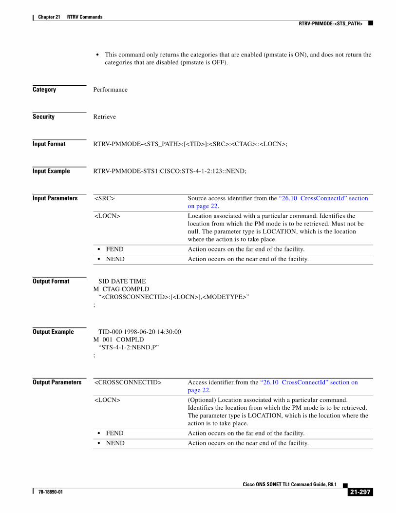
Chapter 21 RTRV CommandsRTRV-PMMODE-<STS_PATH>
• This command only returns the categories that are enabled (pmstate is ON), and does not return the categories that are disabled (pmstate is OFF).
Category Performance
Security Retrieve
Input Format RTRV-PMMODE-<STS_PATH>:[<TID>]:<SRC>:<CTAG>::<LOCN>;
Input Example RTRV-PMMODE-STS1:CISCO:STS-4-1-2:123::NEND;
Input Parameters
Output Format SID DATE TIMEM CTAG COMPLD “<CROSSCONNECTID>:[<LOCN>],<MODETYPE>”;
Output Example TID-000 1998-06-20 14:30:00M 001 COMPLD “STS-4-1-2:NEND,P”;
Output Parameters
<SRC> Source access identifier from the “26.10 CrossConnectId” section on page 22.
<LOCN> Location associated with a particular command. Identifies the location from which the PM mode is to be retrieved. Must not be null. The parameter type is LOCATION, which is the location where the action is to take place.
• FEND Action occurs on the far end of the facility.
• NEND Action occurs on the near end of the facility.
<CROSSCONNECTID> Access identifier from the “26.10 CrossConnectId” section on page 22.
<LOCN> (Optional) Location associated with a particular command. Identifies the location from which the PM mode is to be retrieved. The parameter type is LOCATION, which is the location where the action is to take place.
• FEND Action occurs on the far end of the facility.
• NEND Action occurs on the near end of the facility.
21-297Cisco ONS SONET TL1 Command Guide, R9.1
78-18890-01

Chapter 21 RTRV CommandsRTRV-PMMODE-<VT_PATH>
21.90 RTRV-PMMODE-<VT_PATH>(Cisco ONS 15310-MA) The Retrieve Performance Mode of PM Data Collection for VT1 and VT2 (RTRV-PMMODE-<VT_PATH>) command retrieves the type of PM mode that has been previously set in the NE. This command can be used to identify whether the PM parameters are Section, Line, or Path type, and to identify whether or not the PMs are being collected by the NE.
Usage Guidelines • The PM mode and state of an entity is set by using the SET-PMMODE command.
• This command returns the categories that are enabled (pmstate is ON) only. It does not return the categories that are disabled (pmstate is OFF).
• This release of software will support only the Path (P) mode type PM parameters with this command, that is, this command will not be applicable for Line (L) and Section (S) mode types.
Category Performance
Security Retrieve
Input Format RTRV-PMMODE-<VT_PATH>:[<TID>]:<SRC>:<CTAG>::<LOCN>;
Input Example RTRV-PMMODE-VT1:CISCO:VT-1-1-2-2:1::NEND;
Input Parameters
Output Format SID DATE TIMEM CTAG COMPLD “<CROSSCONNECTID>:<LOCN>,<MODETYPE>”;
<MODETYPE> The type of PM parameters that the entity or the subentity is to store as a result of an attribute change. The parameter type is PM_MODE, which is the type of PM parameters.
• P Transport Path PM parameters.
<SRC> Source access identifier from the “26.10 CrossConnectId” section on page 22.
<LOCN> Location associated with a particular command. Identifies the location from which the PM mode is to be retrieved. Must not be null. The parameter type is LOCATION, which is the location where the action is to take place. Must not be null.
• FEND Action occurs on the far end of the facility.
• NEND Action occurs on the near end of the facility.
21-298Cisco ONS SONET TL1 Command Guide, R9.1
78-18890-01

Chapter 21 RTRV CommandsRTRV-PMSCHED-<MOD2>
Output Example TID-000 1998-06-20 14:30:00M 001 COMPLD “VT1-1-1-2-2:NEND,P”;
Output Parameters
21.91 RTRV-PMSCHED-<MOD2>(Cisco ONS 15454, 15327, 15600, 15310) The Retrieve Performance Monitoring Schedule for 10GFC, 10GIGE, 40GIGE, 1GFC, 1GFICON, 2GFC, 2GFICON, 5GIB, 8GFC, CLNT, D1VIDEO, DS1, DV6000, DVBASI, E1, E3, E4, EC1, ESCON, ETRCLO, ETH, FSTE, G1000, GFPOS, GIGE, HDTV, ISC1, ILK, ISCCOMPAT, ISC3PEER2R, ISC3PEER1G, ISC3PEER2G, OC12, OC192, OC3, OC48, OC768, OCH, OMS, OTS, OTU3, POS, STS1, STS12C, STS18C, STS192C, STS24C, STS36C, STS3C, STS48C, STS96C, STS6C, STS9C, T1, T3, VC12, VC3, VT1, or VT2 (RTRV-PMSCHED-<MOD2>) command retrieves the PM reporting schedule that was set for the NE by the SCHED-PMREPT command.
Usage Guidelines See Table 28-1 on page 1 for supported modifiers by platform.
Category Performance
Security Retrieve
Input Format RTRV-PMSCHED-<MOD2>:[<TID>]:<AID>:<CTAG>;
Input Example RTRV-PMSCHED-OC3:CISCO-NODE:FAC-3-1:123;
<CROSSCONNECTID> Access identifier from the “26.11 CrossConnectId1” section on page 26.
<LOCN> Location associated with a particular command. Identifies the location from which the PM mode is to be retrieved. The parameter type is LOCATION, which is the location where the action is to take place.
• FEND Action occurs on the far end of the facility.
• NEND Action occurs on the near end of the facility.
<MODETYPE> The type of PM parameters that the entity or the subentity is to store as a result of an attribute change. The parameter type is PM_MODE, which is the type of PM parameters.
• P Transport Path PM parameters.
21-299Cisco ONS SONET TL1 Command Guide, R9.1
78-18890-01
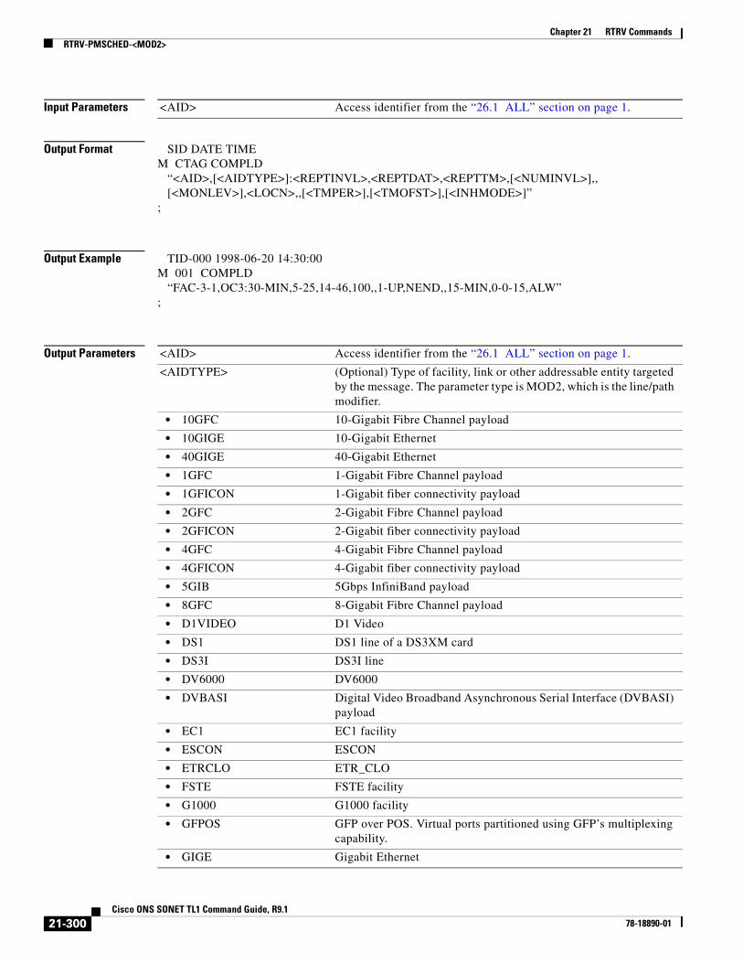
Chapter 21 RTRV CommandsRTRV-PMSCHED-<MOD2>
Input Parameters
Output Format SID DATE TIMEM CTAG COMPLD “<AID>,[<AIDTYPE>]:<REPTINVL>,<REPTDAT>,<REPTTM>,[<NUMINVL>],, [<MONLEV>],<LOCN>,,[<TMPER>],[<TMOFST>],[<INHMODE>]”;
Output Example TID-000 1998-06-20 14:30:00M 001 COMPLD “FAC-3-1,OC3:30-MIN,5-25,14-46,100,,1-UP,NEND,,15-MIN,0-0-15,ALW”;
Output Parameters
<AID> Access identifier from the “26.1 ALL” section on page 1.
<AID> Access identifier from the “26.1 ALL” section on page 1.
<AIDTYPE> (Optional) Type of facility, link or other addressable entity targeted by the message. The parameter type is MOD2, which is the line/path modifier.
• 10GFC 10-Gigabit Fibre Channel payload
• 10GIGE 10-Gigabit Ethernet
• 40GIGE 40-Gigabit Ethernet
• 1GFC 1-Gigabit Fibre Channel payload
• 1GFICON 1-Gigabit fiber connectivity payload
• 2GFC 2-Gigabit Fibre Channel payload
• 2GFICON 2-Gigabit fiber connectivity payload
• 4GFC 4-Gigabit Fibre Channel payload
• 4GFICON 4-Gigabit fiber connectivity payload
• 5GIB 5Gbps InfiniBand payload
• 8GFC 8-Gigabit Fibre Channel payload
• D1VIDEO D1 Video
• DS1 DS1 line of a DS3XM card
• DS3I DS3I line
• DV6000 DV6000
• DVBASI Digital Video Broadband Asynchronous Serial Interface (DVBASI) payload
• EC1 EC1 facility
• ESCON ESCON
• ETRCLO ETR_CLO
• FSTE FSTE facility
• G1000 G1000 facility
• GFPOS GFP over POS. Virtual ports partitioned using GFP’s multiplexing capability.
• GIGE Gigabit Ethernet
21-300Cisco ONS SONET TL1 Command Guide, R9.1
78-18890-01

Chapter 21 RTRV CommandsRTRV-PMSCHED-<MOD2>
• HDTV HDTV
• ISC1 InterSystem Channel, a protocol defined by IBM (ISC1) payload
• ISC3PEER1G 1 Gbps ISC3 Peer
• ISC3PEER2G 2 Gbps ISC3 Peer
• ISC3PEER2R 1 Gbps or 2 Gbps ISC3 peer used in transparent (2R) mode
• ISCCOMPAT 1 Gbps ISC1, ISC2, and ISC3 compatibility
• OC3 OC3 facility
• OC12 OC12 facility
• OC48 OC48 facility
• OC192 OC192 facility
• OC768 OC768 facility
• OCH Optical channel
• OCHCC OCH client connection
• OCHNC OCH network connection
• OCHTERM OCH termination
• OMS Optical Multiplex Section
• OTS Optical Transport Section
• OTU3 Optical Transport Unit Level 3
• POS POS port
• STS1 STS1 path
• STS3C STS3c path
• STS6C STS6c path
• STS9C STS9c path
• STS18C STS18c path
• STS12C STS12c path
• STS24C STS24c path
• STS36C STS36c path
• STS48C STS48c path
• STS192C STS192c path
• T1 T1/DS1 facility/line
• T3 T1/DS1 facility/line
• VT1 VT1 path
• VT2 VT2 path
<REPTINVL> Reporting interval. How often a report is to be generated and sent to the appropriate NE. REPTINVL is a string.
<REPTDAT> Report date. Date for the next report. REPTDAT is a string.
<REPTTM> Report time. The time of day for the next PM report. REPTTM is a string.
Note PM schedule processing is performed every 5 minutes. Therefore, specifying a REPTINVL of 5-MIN or less would be processed at the earliest every 5 minutes.
21-301Cisco ONS SONET TL1 Command Guide, R9.1
78-18890-01

Chapter 21 RTRV CommandsRTRV-PMSCHED-ALL
21.92 RTRV-PMSCHED-ALL(Cisco ONS 15454, 15327, 15600, 15310) The Retrieve Performance Schedule All (RTRV-PMSCHED-ALL) command retrieves all the PM reporting schedules that were set for the NE by the SCHED-PMREPT command.
Usage Guidelines None
<NUMINVL> (Optional) The remaining number of intervals over which the PM will be reported. NUMINVL is an integer.
<LOCN> Location associated with a particular command. Identifies the location from which the PM mode will be retrieved. The parameter type is LOCATION, which is the location where the action is to take place.
• FEND Action occurs on the far end of the facility.
• NEND Action occurs on the near end of the facility.
<TMPER> (Optional) Accumulation time period for performance counters. The parameter type is TMPER, which is the accumulation time period for the performance management center.
• 1-DAY Performance parameter accumulation interval length; every 24 hours. For SONET PM data, only one day of history data is available. For RMON managed PM data, seven days of history data are available.
• 1-HR Performance parameter accumulation interval length; every 1 hour. This is only applicable to RMON managed PM data. There are 24 hours of history data available.
• 1-MIN Performance parameter accumulation interval length; every 1 minute. This is only applicable to RMON managed PM data. There are 60 minutes of history available.
• 15-MIN Performance parameter accumulation interval length; every 15 minutes. There are 32 15-MIN buckets of history data available for this accumulation interval length.
• RAW-DATA Performance parameter accumulation interval length; starting from the last time the counters were cleared. This is only applicable to RMON managed PMs.
<TMOFST> (Optional) Time offset between reporting/diagnostics/exercises; from the end of the last complete accumulation time period to the beginning of the accumulation time period specified by TMPER. TMOFST is a string.
<INHMODE> (Optional) Indicates whether a function is inhibited by an INH command. Indicates whether the reporting of PM data is inhibited (by the INH-PMREPT-ALL command) or is allowed (by the ALW-PMREPT-ALL command). The parameter type is INH_MODE, which indicates whether the function is inhibited.
• ALW Function is allowed.
• INH Function is inhibited.
21-302Cisco ONS SONET TL1 Command Guide, R9.1
78-18890-01

Chapter 21 RTRV CommandsRTRV-PMSCHED-ALL
Category Performance
Security Retrieve
Input Format RTRV-PMSCHED-ALL:[<TID>]::<CTAG>;
Input Example RTRV-PMSCHED-ALL:CISCO-NODE::123;
Input Parameters None that require description
Output Format SID DATE TIMEM CTAG COMPLD “<AID>,[<AIDTYPE>]:<REPTINVL>,<REPTDAT>,<REPTTM>,[<NUMINVL>],, [<MONLEV>],<LOCN>,,[<TMPER>],<TMOFST>,[<INHMODE>]”;
Output Example TID-000 1998-06-20 14:30:00M 001 COMPLD “FAC-3-1,OC3:30-MIN,5-25,14-46,100,,1-UP,NEND,,15-MIN,0-0-15,ALW”;
Output Parameters <AID> Access identifier from the “26.1 ALL” section on page 1.
<AIDTYPE> (Optional) Type of facility, link or other addressable entity targeted by the message. The parameter type is MOD2, which is the line/path modifier.
• 10GFC 10-Gigabit Fibre Channel payload
• 10GIGE 10-Gigabit Ethernet
• 1GFC 1-Gigabit Fibre Channel payload
• 1GFICON 1-Gigabit fiber connectivity payload
• 2GFC 2-Gigabit Fibre Channel payload
• 2GFICON 2-Gigabit fiber connectivity payload
• 4GFC 4-Gigabit Fibre Channel payload
• 4GFICON 4-Gigabit fiber connectivity payload
• 40GIGE 40-Gigabit Ethernet
• 5GIB 5Gbps InfiniBand payload
• 8GFC 8-Gigabit Fibre Channel payload
• D1VIDEO D1 Video
21-303Cisco ONS SONET TL1 Command Guide, R9.1
78-18890-01
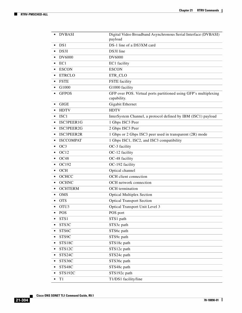
Chapter 21 RTRV CommandsRTRV-PMSCHED-ALL
• DVBASI Digital Video Broadband Asynchronous Serial Interface (DVBASI) payload
• DS1 DS-1 line of a DS3XM card
• DS3I DS3I line
• DV6000 DV6000
• EC1 EC1 facility
• ESCON ESCON
• ETRCLO ETR_CLO
• FSTE FSTE facility
• G1000 G1000 facility
• GFPOS GFP over POS. Virtual ports partitioned using GFP’s multiplexing capability.
• GIGE Gigabit Ethernet
• HDTV HDTV
• ISC1 InterSystem Channel, a protocol defined by IBM (ISC1) payload
• ISC3PEER1G 1 Gbps ISC3 Peer
• ISC3PEER2G 2 Gbps ISC3 Peer
• ISC3PEER2R 1 Gbps or 2 Gbps ISC3 peer used in transparent (2R) mode
• ISCCOMPAT 1 Gbps ISC1, ISC2, and ISC3 compatibility
• OC3 OC-3 facility
• OC12 OC-12 facility
• OC48 OC-48 facility
• OC192 OC-192 facility
• OCH Optical channel
• OCHCC OCH client connection
• OCHNC OCH network connection
• OCHTERM OCH termination
• OMS Optical Multiplex Section
• OTS Optical Transport Section
• OTU3 Optical Transport Unit Level 3
• POS POS port
• STS1 STS1 path
• STS3C STS3c path
• STS6C STS6c path
• STS9C STS9c path
• STS18C STS18c path
• STS12C STS12c path
• STS24C STS24c path
• STS36C STS36c path
• STS48C STS48c path
• STS192C STS192c path
• T1 T1/DS1 facility/line
21-304Cisco ONS SONET TL1 Command Guide, R9.1
78-18890-01

Chapter 21 RTRV CommandsRTRV-PMSCHED-ALL
• T3 T1/DS1 facility/line
• VT1 VT1 path
• VT2 VT2 path
<REPTINVL> Reporting interval. How often a report is to be generated and sent to the appropriate NE. REPTINVL is a string.
<REPTDAT> Report date. Date for the next report. REPTDAT is a string.
<REPTTM> Report time. The time of day for the next PM report. REPTTM is a string.
<NUMINVL> (Optional) The remaining number of intervals over which PM is to be reported. NUMINVL is an integer.
<LOCN> Location associated with a particular command. Identifies the location from which the PM mode is to be retrieved. The parameter type is LOCATION, which is the location where the action is to take place.
• FEND Action occurs on the far end of the facility.
• NEND Action occurs on the near end of the facility.
<TMPER> (Optional) Accumulation time period for performance counters. The parameter type is TMPER, which is the accumulation time period for the performance management center.
• 1-DAY Performance parameter accumulation interval length; every 24 hours. For SONET PM data, only one day of history data is available. For RMON managed PM data, seven days of history data are available.
• 1-HR Performance parameter accumulation interval length; every 1 hour. This is only applicable to RMON managed PM data. There are 24 hours of history data available.
• 1-MIN Performance parameter accumulation interval length; every 1 minute. This is only applicable to RMON managed PM data. There are 60 minutes of history available.
• 15-MIN Performance parameter accumulation interval length; every 15 minutes. There are 32 15-MIN buckets of history data available for this accumulation interval length.
• RAW-DATA Performance parameter accumulation interval length; starting from the last time the counters were cleared. This is only applicable to RMON managed PMs.
<TMOFST> (Optional) Time offset between reporting/diagnostics/exercises; from the end of the last complete accumulation time period to the beginning of the accumulation time period specified by TMPER. TMOFST is a string.
<INHMODE> (Optional) Indicates whether a function is inhibited by an INH command. Indicates whether the reporting of PM data is inhibited (by the INH-PMREPT-ALL command) or is allowed (by the ALW-PMREPT-ALL command). The parameter type is INH_MODE, which indicates whether the function is inhibited.
• ALW Function is allowed.
• INH Function is inhibited.
21-305Cisco ONS SONET TL1 Command Guide, R9.1
78-18890-01

Chapter 21 RTRV CommandsRTRV-POS
21.93 RTRV-POS(Cisco ONS 15310-CL, Cisco ONS 15310-MA, Cisco ONS 15454, and Cisco ONS 15600) The Retrieve Packet Over SONET (RTRV-POS) command retrieves the back-end port information for the Ethernet card when the back-end port is working in POS mode.
Usage Guidelines • This command is supported for the ML-Series cards, but for the ONS 15310-CL ML-100T-8 card, ADMINSTATE, ENCAP, SOAK, and SOAKLEFT information will not appear.
• For the ML-Series card, the EDGE, RPRSPAN, JUMBO, ADMINSTATE, ENCAP, and NAME parameters are valid when the card mode is ML-IEEE-RPR. Other parameters, including PST and SST, are not valid in this mode.
• This command is supported for the ASAP card, but ADMINSTATE information will not appear.
• Because the back-end port is virtual, the Virtual Facility (VFAC) AID should be used when issuing the command.
Category Ports
Security Retrieve
Input Format RTRV-POS:[<TID>]:<AID>:<CTAG>;
Input Example RTRV-POS:TID:VFAC-1-1:CTAG;
Input Parameters
Output Format SID DATE TIMEM CTAG COMPLD “<AID>::[ADMINSTATE=<ADMINSTATE>],[JUMBO=<MTU>],[ENCAP=<ENCAP>], [RPRSPAN=<RPRSPAN>],[EDGE=<EDGE>],[NAME=<NAME>]:”;;
Output Example TID-000 1998-06-20 14:30:00M 001 COMPLD “VFAC-1-1::ADMINSTATE=DOWN,JUMBO=N,ENCAP=RPR-GFP-F,RPRSPAN=EAST, EDGE=Y,NAME=\"RPR\":";
<AID> Access identifier from the “26.15 FACILITY” section on page 35.
21-306Cisco ONS SONET TL1 Command Guide, R9.1
78-18890-01

Chapter 21 RTRV CommandsRTRV-PROTNSW-<MOD2DWDMPAYLOAD>
Output Parameters
21.94 RTRV-PROTNSW-<MOD2DWDMPAYLOAD>(Cisco ONS 15454) The Retrieve Protection Switch for 10GFC, 10GIGE, 40GIGE, 1GFC, 1GFICON, 2GFC, 2GFICON, 8GFC, D1VIDEO, DV6000, DVBASI, ETRCLO, FSTE, GIGE, HDTV, ISC1, ISC3, OTU3, or PASSTHRU (RTRV-PROTNSW-<MOD2DWDMPAYLOAD>) command retrieves the protection switch status of client facilities.
Usage Guidelines None
Category DWDM
Security Retrieve
Input Format RTRV-PROTNSW-<MOD2DWDMPAYLOAD>:[<TID>]:<SRC>:<CTAG>[::::];
Input Example RTRV-PROTNSW-HDTV:CISCO:FAC-1-1-1:100;
Input Parameters
<AID> Access identifier from the “26.15 FACILITY” section on page 35.
<ADMINSTATE> (Optional) Administration type. The parameter type is UP_DOWN (up or down).
• DOWN Down
• UP Up
<ENCAP> Frame encapsulation
• RPR-GFP-F RPR-over-GFP frame mode
<JUMBO> Jumbo frame values
• Y Yes
• N No
<RPRSPAN> RPR span values
• EAST East direction
• WEST West direction
<EDGE> RPR edge values
• Y Yes
• N No
<NAME> Port name, facility name, or VCAT group name
<SRC> Source access identifier from the “26.15 FACILITY” section on page 35.
21-307Cisco ONS SONET TL1 Command Guide, R9.1
78-18890-01

Chapter 21 RTRV CommandsRTRV-PROTNSW-<OCN_TYPE>
Output Format SID DATE TIMEM CTAG COMPLD “<AIDUNIONID>:<SC>,[<SWITCHTYPE>]”;
Output Example TID-000 1998-06-20 14:30:00M 001 COMPLD “FAC-1-1-1:FRCD,MANWKSWBK”;
Output Parameters
21.95 RTRV-PROTNSW-<OCN_TYPE>(Cisco ONS 15454, 15327, 15600, 15310) The Retrieve Protection Switch for OC3, OC12, OC48, OC192, OC768 (RTRV-PROTNSW-<OCN_TYPE>) command retrieves the switching state of a SONET line specified in the AID.
<AIDUNIONID> Access identifier from the “26.15 FACILITY” section on page 35.
<SC> Switch command to be initiated on the paths. The parameter type is SW, which is the type of switch to be initiated.
• APS-CLEAR APS-CLEAR switch state. It is a read-only switch state and is not allowed in the OPR-PROTNSW-xxx commands.
• CLEAR CLEAR switch state. CLEAR switch state is not allowed in the OPR-PROTNSW-xxx commands.
• EXERCISE EXERCISE switch state. EXERCISE switch state is not allowed in the OPR-PROTNSW-xxx commands.
• FRCD Forces a switch unless another FRCD or LOCKOUT is in effect.
• LOCKOUT Locks the facility out of switching. The system cannot switch to this facility to carry service.
• MAN Requests a manual switch of the facility.
<SWITCHTYPE> (Optional) Switch type. The parameter type is SWITCH_TYPE, which is the BLSR switch type. MANWKSWBK, MANWKSWPR, FRCDWKSWBK, FRCDWKSWPR, LOCKOUTOFPR, and LOCKOUTOFWK are retrieve-only values for RTRV-PROTNSW-OCn commands. They are not applicable for the OPR-PROTNSW-OCn commands. RING and SPAN are the only allowed values for BLSR protection.
• FRCDWKSWBK Working unit is forced to switch back to working.
• FRCDWKSWPR Working unit is forced to switch to the protection unit.
• LOCKOUTOFPR Lockout of protection.
• LOCKOUTOFWK Lockout of working.
• MANWKSWBK Manual switch of working unit back to working.
• MANWKSWPR Manual switch of working unit back to the protection unit.
• RING BLSR ring switch type.
• SPAN BLSR span switch type.
21-308Cisco ONS SONET TL1 Command Guide, R9.1
78-18890-01

Chapter 21 RTRV CommandsRTRV-PROTNSW-<OCN_TYPE>
Usage Guidelines See Table 28-1 on page 1 for supported modifiers by platform.
Category Protection
Security Retrieve
Input Format RTRV-PROTNSW-<OCN_TYPE>:[<TID>]:<AID>:<CTAG>[::::];
Input Example RTRV-PROTNSW-OC48:CISCO:FAC-5-1:123;
Input Parameters
Output Format SID DATE TIMEM CTAG COMPLD “<AID>:<SC>,[<SWITCHTYPE>]”;
Output Example TID-000 1998-06-20 14:30:00M 001 COMPLD “FAC-5-1:MAN,MANWKSWBK”;
Output Parameters
<AID> Access identifier from the “26.15 FACILITY” section on page 35.
<AID> Access identifier from the “26.15 FACILITY” section on page 35.
<SC> Switch command to be initiated on the paths. The parameter type is SW, which is the type of switch to be initiated.
• APS-CLEAR APS-CLEAR switch state. It is a read-only switch state and is not allowed in the OPR-PROTNSW-xxx commands.
• CLEAR CLEAR switch state. CLEAR switch state is not allowed in the OPR-PROTNSW-xxx commands.
• EXERCISE EXERCISE switch state. EXERCISE switch state is not allowed in the OPR-PROTNSW-xxx commands.
• FRCD Forces a switch unless another FRCD or LOCKOUT is in effect.
• LOCKOUT Locks the facility out of switching. The system cannot switch to this facility to carry service.
• MAN Requests a manual switch of the facility.
21-309Cisco ONS SONET TL1 Command Guide, R9.1
78-18890-01

Chapter 21 RTRV CommandsRTRV-PROTNSW-<PATH>
21.96 RTRV-PROTNSW-<PATH>(Cisco ONS 15454, 15327, 15600, 15310) The Retrieve Protection Switch for STS1, STS12C, STS18C, STS192C, STS24C, STS36C, STS3C, STS48C, STS96C, STS6C, STS9C, VT1, or VT2 (RTRV-PROTNSW-<PATH>) command retrieves the switching state of a SONET path protection STS path specified in the AID. Because Telcordia GR-1400 does not allow LOCKOUT_OF_WORKING on the path protection WORKING path/AID, the “AID:LOCKOUT,LOCKOUTOFWK” does not appear in this protection switch retrieval result.
Usage Guidelines See Table 28-1 on page 1 for supported modifiers by platform.
Note RTRV-PROTNSW-VT1 accepts STS-1 AID when STS-1 cross connection is made using the DS1 card. This will allow the user to retrieve all the VT1 conditions/alarms that are raised by DS-1 card when STS-1 cross connect is created.
Category Protection
Security Retrieve
Input Format RTRV-PROTNSW-<PATH>:[<TID>]:<SRC>:<CTAG>[::::];
Input Example RTRV-PROTNSW-STS1:CISCO:STS-5-1-1:123;
<SWITCHTYPE> (Optional) Switch type. The parameter type is SWITCH_TYPE, which is the BLSR switch type. MANWKSWBK, MANWKSWPR, FRCDWKSWBK, FRCDWKSWPR, LOCKOUTOFPR, and LOCKOUTOFWK are retrieve-only values for RTRV-PROTNSW-OCn commands. They are not applicable for the OPR-PROTNSW-OCn commands. RING and SPAN are the only allowed values for BLSR protection.
• FRCDWKSWBK Working unit is forced to switch back to working.
• FRCDWKSWPR Working unit is forced to switch to the protection unit.
• LOCKOUTOFPR Lockout of protection.
• LOCKOUTOFWK Lockout of working.
• MANWKSWBK Manual switch of working unit back to working.
• MANWKSWPR Manual switch of working unit back to the protection unit.
• RING BLSR ring switch type.
• SPAN BLSR span switch type.
21-310Cisco ONS SONET TL1 Command Guide, R9.1
78-18890-01
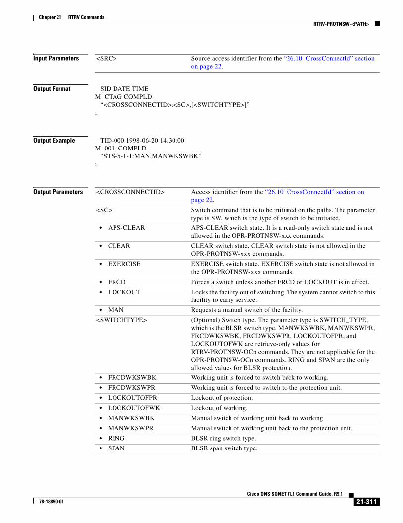
Chapter 21 RTRV CommandsRTRV-PROTNSW-<PATH>
Input Parameters
Output Format SID DATE TIMEM CTAG COMPLD “<CROSSCONNECTID>:<SC>,[<SWITCHTYPE>]”;
Output Example TID-000 1998-06-20 14:30:00M 001 COMPLD “STS-5-1-1:MAN,MANWKSWBK”;
Output Parameters
<SRC> Source access identifier from the “26.10 CrossConnectId” section on page 22.
<CROSSCONNECTID> Access identifier from the “26.10 CrossConnectId” section on page 22.
<SC> Switch command that is to be initiated on the paths. The parameter type is SW, which is the type of switch to be initiated.
• APS-CLEAR APS-CLEAR switch state. It is a read-only switch state and is not allowed in the OPR-PROTNSW-xxx commands.
• CLEAR CLEAR switch state. CLEAR switch state is not allowed in the OPR-PROTNSW-xxx commands.
• EXERCISE EXERCISE switch state. EXERCISE switch state is not allowed in the OPR-PROTNSW-xxx commands.
• FRCD Forces a switch unless another FRCD or LOCKOUT is in effect.
• LOCKOUT Locks the facility out of switching. The system cannot switch to this facility to carry service.
• MAN Requests a manual switch of the facility.
<SWITCHTYPE> (Optional) Switch type. The parameter type is SWITCH_TYPE, which is the BLSR switch type. MANWKSWBK, MANWKSWPR, FRCDWKSWBK, FRCDWKSWPR, LOCKOUTOFPR, and LOCKOUTOFWK are retrieve-only values for RTRV-PROTNSW-OCn commands. They are not applicable for the OPR-PROTNSW-OCn commands. RING and SPAN are the only allowed values for BLSR protection.
• FRCDWKSWBK Working unit is forced to switch back to working.
• FRCDWKSWPR Working unit is forced to switch to the protection unit.
• LOCKOUTOFPR Lockout of protection.
• LOCKOUTOFWK Lockout of working.
• MANWKSWBK Manual switch of working unit back to working.
• MANWKSWPR Manual switch of working unit back to the protection unit.
• RING BLSR ring switch type.
• SPAN BLSR span switch type.
21-311Cisco ONS SONET TL1 Command Guide, R9.1
78-18890-01

Chapter 21 RTRV CommandsRTRV-PROTNSW-OCH
21.97 RTRV-PROTNSW-OCH(Cisco ONS 15454) The Retrieve Protection Switch Optical Channel (RTRV-PROTNSW-OCH) command retrieves the protection switch status of the TXPP_MR_2.5G and MXPP_MR_2.5G card’s splitter protection group (of its working and protected trunk ports).
Usage Guidelines None
Category DWDM
Security Retrieve
Input Format RTRV-PROTNSW-OCH:[<TID>]:<AID>:<CTAG>;
Input Example RTRV-PROTNSW-OCH:VA454-22:CHAN-2-2:100;
Input Parameters
Output Format SID DATE TIMEM CTAG COMPLD “<AID>:<SW>,<SWTYPE>”;
Output Example TID-000 1998-06-20 14:30:00M 001 COMPLD “CHAN-2-2:FRCD,FRCDWKSWBK”;
Output Parameters
<AID> Access identifier from the “26.8 CHANNEL” section on page 19.
<AID> Access identifier from the “26.8 CHANNEL” section on page 19.
<SW> Indicates the switch operation. The parameter type is SW, which is the type of switch to be initiated.
• APS-CLEAR APS-CLEAR switch state. It is a read-only switch state and is not allowed in the OPR-PROTNSW-xxx commands.
• CLEAR CLEAR switch state. CLEAR switch state is not allowed in the OPR-PROTNSW-xxx commands.
• EXERCISE EXERCISE switch state. EXERCISE switch state is not allowed in the OPR-PROTNSW-xxx commands.
• FRCD Forces a switch unless another FRCD or LOCKOUT is in effect.
21-312Cisco ONS SONET TL1 Command Guide, R9.1
78-18890-01

Chapter 21 RTRV CommandsRTRV-PROTNSW-OTS
21.98 RTRV-PROTNSW-OTS(Cisco ONS 15454) The Retrieve Protection Switch OTS (RTRV-PROTNSW-OTS) command retrieves the protection switch status of the PSM splitter protection group (of its working and protected OTS RX ports).
Usage Guidelines None
Category DWDM
Security Retrieve
Input Format RTRV-PROTNSW-OTS:[<TID>]:<AID>:<CTAG>;
Input Example RTRV-PROTNSW-OTS:VA454-22:CHAN-2-2:100;
Input Parameters
• LOCKOUT Locks the facility out of switching. The system cannot switch to this facility to carry service.
• MAN Requests a manual switch of the facility.
<SWITCHTYPE> Indicates the switch type operation. The parameter type is SWITCH_TYPE, which is the BLSR switch type. MANWKSWBK, MANWKSWPR, FRCDWKSWBK, FRCDWKSWPR, LOCKOUTOFPR, and LOCKOUTOFWK are retrieve-only values for RTRV-PROTNSW-OCn commands. They are not applicable for the OPR-PROTNSW-OCn commands. RING and SPAN are the only allowed values for BLSR protection.
• FRCDWKSWBK Working unit is forced to switch back to working.
• FRCDWKSWPR Working unit is forced to switch to the protection unit.
• LOCKOUTOFPR Lockout of protection.
• LOCKOUTOFWK Lockout of working.
• MANWKSWBK Manual switch of working unit back to working.
• MANWKSWPR Manual switch of working unit back to the protection unit.
• RING BLSR ring switch type.
• SPAN BLSR span switch type.
<AID> Access identifier from the “26.8 CHANNEL” section on page 19.
21-313Cisco ONS SONET TL1 Command Guide, R9.1
78-18890-01

Chapter 21 RTRV CommandsRTRV-PROTOCOL
Output Format SID DATE TIMEM CTAG COMPLD “<AID>:<SW>,<SWTYPE>”;
Output Example TID-000 1998-06-20 14:30:00M 001 COMPLD “CHAN-2-2:FRCD,FRCDWKSWBK”;
Output Parameters
21.99 RTRV-PROTOCOL(Cisco ONS 15454, 15327, 15600, 15310) The Retrieve Protocol (RTRV-PROTOCOL) command retrieves the status of a protocol or service supported in the NE. Valid protocols include SHELL, EMS, TL1, and SNMP. If the AID is not specified, the status of all the protocols is retrieved.
<AID> Access identifier from the “26.8 CHANNEL” section on page 19.
<SW> Indicates the switch operation. The parameter type is SW, which is the type of switch to be initiated.
• APS-CLEAR APS-CLEAR switch state. It is a read-only switch state and is not allowed in the OPR-PROTNSW-xxx commands.
• CLEAR CLEAR switch state. CLEAR switch state is not allowed in the OPR-PROTNSW-xxx commands.
• EXERCISE EXERCISE switch state. EXERCISE switch state is not allowed in the OPR-PROTNSW-xxx commands.
• FRCD Forces a switch unless another FRCD or LOCKOUT is in effect.
• LOCKOUT Locks the facility out of switching. The system cannot switch to this facility to carry service.
• MAN Requests a manual switch of the facility.
<SWITCHTYPE> Indicates the switch type operation. The parameter type is SWITCH_TYPE, which is the BLSR switch type. MANWKSWBK, MANWKSWPR, FRCDWKSWBK, FRCDWKSWPR, LOCKOUTOFPR, and LOCKOUTOFWK are retrieve-only values for RTRV-PROTNSW-OCn commands. They are not applicable for the OPR-PROTNSW-OCn commands. RING and SPAN are the only allowed values for BLSR protection.
• FRCDWKSWBK Working unit is forced to switch back to working.
• FRCDWKSWPR Working unit is forced to switch to the protection unit.
• LOCKOUTOFPR Lockout of protection.
• LOCKOUTOFWK Lockout of working.
• MANWKSWBK Manual switch of working unit back to working.
• MANWKSWPR Manual switch of working unit back to the protection unit.
• RING BLSR ring switch type.
• SPAN BLSR span switch type.
21-314Cisco ONS SONET TL1 Command Guide, R9.1
78-18890-01

Chapter 21 RTRV CommandsRTRV-PROTOCOL
Usage Guidelines If the AID is TL1, the status can be retrieved to show if the protocol is in SECURE or UNSECURE mode.
Category Security
Security Retrieve
Input Format RTRV-PROTOCOL:[<TID>]:[<AID>]:<CTAG>;
Input Example RTRV-PROTOCOL::EMS:123;
Input Parameters
Output Format SID DATE TIMEM CTAG COMPLD “<PROTOCOLAID>:<PROTOCOLSTAT>”;
Output Example TID-000 1998-06-20 14:30:00M 001 COMPLD “EMS:UNSECURE”;
Output Parameters
<AID> (Optional) Identifies the protocol or service to which the command pertains. Defaults to ALL. A null value is equivalent to ALL. The parameter type is PROTOCOLAID, which is the AID for the protocol/service.
• EMS CTC/CTM protocol/service
• SHELL Shell/file system access protocol
• SNMP SNMP protocol/service
• TL1 TL1 protocol service
PROTOCOLAID Identifies the protocol or service to which the command pertains. The parameter type is PROTOCOLAID, which is the AID for the protocol/service.
• EMS CTC/CTM protocol/service
• SHELL Shell/file system access protocol
• SNMP SNMP protocol/service
• TL1 TL1 protocol/service
PROTOCOLSTAT Identifies the status of the protocol or service. The parameter type is PROTOCOLSTAT, which is the status of the protocol.
21-315Cisco ONS SONET TL1 Command Guide, R9.1
78-18890-01

Chapter 21 RTRV CommandsRTRV-PTHTRC-<PATH>
21.100 RTRV-PTHTRC-<PATH>(Cisco ONS 15454, 15327, 15600, 15310) The Retrieve Path Trace for STS1, STS12C, STS18C, STS192C, STS24C, STS36C, STS3C, STS48C, STS96C, STS6C, STS9C, VT1, or VT2 (RTRV-PTHTRC-<PATJ>) command retrieves the contents of the SONET path trace message.
Usage Guidelines See Table 28-1 on page 1 for supported modifiers by platform.
The path trace message is a 64-character string with the last two characters reserved for the terminating CR (carriage return) and the LF (line feed). The message can be an incoming path trace message, an expected incoming path trace message, or an outgoing path trace message, which is inserted into the path overhead of the outgoing signal.
The path trace mode has three modes: OFF, MANUAL, and AUTO. The path trace mode defaults to OFF mode. The MANUAL mode performs the comparison of the received string with the user-entered expected string. The AUTO mode performs the comparison of the present received string with an expected string set to a previously received string. If there is a mismatch, the TIM-P alarm is raised. When the path trace mode is in OFF mode, there is no path trace processing, and all the alarm and state conditions are reset.
When the expected string is queried under the OFF path trace mode, the expected string is a copy of the provisioned string or NULL. When an expected string is queried under the MANUAL path trace mode, the expected string is a copy of the user-entered string. When an expected string is queried under the AUTO path trace mode, the expected string is a copy of the acquired received string or NULL if the string has not been acquired.
When the incoming string is queried under the OFF path trace mode, the incoming string is NULL. When an incoming string is queried under the MANUAL or AUTO path trace mode, the incoming string is a copy of the received string or NULL if the string has not been received.
When the transmitted string is queried under the OFF, MANUAL, or AUTO path trace mode, the transmitted string is the provisioned transmit string.
Note • A null value for the MSGTYPE defaults to INCTRC.
• Only the NEND location value is supported. A null value of the location defaults to NEND.
• Sending a FEND of the location with this command will return an “unsupported locn value” error message.
• J1 (EXPTRC/INCTRC) is implemented on the DS1/DS1N, DS3E/DS3NE, DS3XM, EC1, OC3, OC48A, OC192, OC192-XFP, and MRC-12 cards.
• TRC is supported only on DS1(N), DS3(N)E, and DS3XM cards.
• The VCAF AID is only valid on slots holding ML-Series cards.
• DISABLED The protocol cannot be used.
• SECURE The protocol is enabled and communications using the protocol are sure, for example, through SSH. Not applicable for SNMP protocols.
• UNSECURE The protocol is enabled but communication is not secure, for example, through Telnet.
21-316Cisco ONS SONET TL1 Command Guide, R9.1
78-18890-01

Chapter 21 RTRV CommandsRTRV-PTHTRC-<PATH>
• After the BLSR switch, the working path is switched out and the traffic goes through the protection path. The J1 trace message can be retrieved from the protection STS path.
• If there is an STS PCA on the protection path during the BLSR switch, the PCA path is preemptive. If this command is sent on the protection path after a BLSR switch, the command will return the trace message off of the protection path and not from the PCA path.
• The J2 path trace on the VT1.5 is supported on the VT1.5 cross-connection of the DS3XM-12 card in Software R5.0 and later.
• The VT2 modifier is not supported in this release.
• According to Telcordia GR-833, RTRV-PTHTRC-<PATH> can only have a single output row, therefore you cannot specify multiple AIDs using '&' with this command because each AID would require it's own output row. You also cannot use the AIDs that end in ALL because this might also result in multiple output rows.
• On the ONS 15310-MA, J2 path trace is supported on DS1 ports only. J2 path trace is not supported on ONS 15310-MA OCn ports and EC1 ports.
Category Troubleshooting and Test Access
Security Retrieve
Input Format RTRV-PTHTRC-<PATH>:[<TID>]:<SRC>:<CTAG>::[<MSGTYPE>][:<LOCN>];
Input Example RTRV-PTHTRC-STS1:CISCO:STS-2-1-1:123::EXPTRC:NEND;
Input Parameters
Output Format SID DATE TIMEM CTAG COMPLD “<TRACMSG>”;
<SRC> Source access identifier from the “26.10 CrossConnectId” section on page 22.
<MSGTYPE> Type of autonomous message to be retrieved. A null value defaults to INCTRC. The parameter type is MSGTYPE, which is the type of trace message.
• EXPTRC Expected incoming path trace message
• INCTRC Incoming path trace message
• TRC Outgoing path trace message
<LOCN> Location associated with a particular command in reference to the entity identified by the AID. The parameter type is LOCATION, which is the location where the action is to take place.
• FEND Action occurs on the far end of the facility.
• NEND Action occurs on the near end of the facility.
21-317Cisco ONS SONET TL1 Command Guide, R9.1
78-18890-01

Chapter 21 RTRV CommandsRTRV-QNQ-ETH
Output Example TID-000 1998-06-20 14:30:00M 001 COMPLD “TRACMSG”;
Output Parameters
21.101 RTRV-QNQ-ETH(Cisco ONS 15454) The Retrieve QinQ Ethernet (RTRV-QNQ-ETH) command retrieves the IEEE 802.1Q tunneling (QinQ) relationship between the CE-VLAN and the S-VLAN for Gigabit Ethernet uniport provisioning associated to an L2 Ethernet port.
Usage Guidelines None
Category Ethernet
Security Retrieve
Input Format RTRV-QNQ-ETH:[<TID>]:<AID>:<CTAG>::<FIRSTCEVLANID>,<LASTCEVLANID>,<SVLANID>[:];
Input Example RTRV-QNQ-ETH:PETALUMA:ETH-1-1-1:236::110,110,1208;
Input Parameters
<TRACMSG> The path trace message returned to the requester. The message can be up to 64 characters in length with the last two characters reserved for the CR (carriage return) and the LF (line feed). TRACMSG is a string.
<AID> Ethernet AIDs are used to access L2 Ethernet ports. Access identifier from the “26.15 FACILITY” section on page 35.
<FIRSTCEVLANID> VLAN identifier. A VLAN ID is a number between 1 and 4096. The Access identifier from the “26.15 FACILITY” section on page 35. Value 0 is reserved for untagged VLANs. This identifier is used for customer VLAN IDs and service provider VLAN IDs.
21-318Cisco ONS SONET TL1 Command Guide, R9.1
78-18890-01

Chapter 21 RTRV CommandsRTRV-RAMAN
Output Format SID DATE TIMEM CTAG COMPLD “<AID>:<FIRSTCEVLANID>,<LASTCEVLANID>,<SVLANID>:RULE=<RULE>[:]”;
Output Example TID-000 1998-06-20 14:30:00M 001 COMPLD “ETH-1-1-1:110,111,1208:RULE=XLTE:”;
Output Parameters
21.102 RTRV-RAMAN(Cisco ONS 15454)
Retrieve RAMAN retrieves the attributes of a RAMAN measure.
Usage Guidelines None
<LASTCEVLANID> VLAN identifier. A VLAN ID is a number between 1 and 4096. The value 0 is reserved for untagged VLANs. This identifier is used for customer VLAN IDs and service provider VLAN IDs.
<SVLANID> VLAN identifier. A VLAN ID is a number between 1 and 4096. The value 0 is reserved for untagged VLANs. This identifier is used for customer VLAN IDs and service provider VLAN IDs.
<AID> Ethernet AIDs are used to access L2 Ethernet ports. Access identifier from the “26.15 FACILITY” section on page 35.
<FIRSTCEVLANID> VLAN identifier. A VLAN ID is a number between 1 and 4096. The value 0 is reserved for untagged VLANs. This identifier is used for customer VLAN IDs and service provider VLAN IDs.
<LASTCEVLANID> VLAN identifier. A VLAN ID is a number between 1 and 4096. The value 0 is reserved for untagged VLANs. This identifier is used for customer VLAN IDs and service provider VLAN IDs.
<SVLANID> VLAN identifier. A VLAN ID is a number between 1 and 4096. The value 0 is reserved for untagged VLANs. This identifier is used for customer VLAN IDs and service provider VLAN IDs.
<RULE> Used to represent the Rules allowed for VLAN tagging operations. Default is ADD.
• ADD The S-VLAN tag is added to the CE-VLAN tag.
• XLTE The S-VLAN tag substitutes the CE-VLAN tag (single Q).
21-319Cisco ONS SONET TL1 Command Guide, R9.1
78-18890-01

Chapter 21 RTRV CommandsRTRV-RAMAN
Category DWDM
Security Retrieve
Input Format RTRV-RAMAN:[<TID>]:<AID>:<CTAG>;
Input Example RTRV-RAMAN:PENNGROVE:LINE-6-1-TX:236;
Input Parameter
Output Format SID DATE TIMEM CTAG COMPLD “<AID>:<MEAS_INDEX>:<MINRAMANLEV>,<MAXRAMANLEV>,<DATE>,<TIME>”;;
Output Example TID-000 1998-06-20 14:30:00M 001 COMPLD“LINE-6-1-TX:1:MINRAMANLEV=1.0,MAXRAMANLEV=2.0,TIME=00-00-00,DATE=02-02-07;”
;
Output Parameters
<AID> The LINE AID is used to access Optical Transport Section (OTS) layer of Optical Network units.
• LINE[-{1-12}]-{1-5,12-16}-{1-5}-{RX,TX}
The receive/transmit Lines (COM=1, OSC=2, LINE=3, DC=4, RAMAN=5) in a OPT-RAMP-C card.
• LINE[-{1-12}]-{1-5,12-16}-{1-5}-ALL
All the Lines (COM=1,OSC=2,LINE=3, DC=4, RAMAN=5) in a OPT-RAMP-C card.
<AID> The LINE aid is used to access Optical Transport Section (OTS) layer of Optical Network units.
• LINE[-{1-12}]-{1-5,12-16}-{1-5}-{RX,TX}
The receive/transmit Lines (COM=1, OSC=2, LINE=3, DC=4, RAMAN=5) in a OPT-RAMP-C card.
• LINE[-{1-12}]-{1-5,12-16}-{1-5}-ALL
All the Lines (COM=1,OSC=2,LINE=3, DC=4, RAMAN=5) in a OPT-RAMP-C card.
<MEAS_INDEX > Raman measure Index.
<MINRAMANLEV> Power measured with MIN raman power level.
<MAXRAMANLEV > Power measured with MAX raman power level.
<DATE> Identifies the date. Date is a string. Default value is - “current date”.
<TIME> Identifies the time. Time is a string. Default value is - “current time.”
21-320Cisco ONS SONET TL1 Command Guide, R9.1
78-18890-01

Chapter 21 RTRV CommandsRTRV-RMONTH-<MOD2_RMON>
21.103 RTRV-RMONTH-<MOD2_RMON>(Cisco ONS 15454, ONS 15600, ONS 15310-CL, and ONS 15310-MA) The Retrieve Remote Monitoring Threshold for 10GFC, 10GIGE, 40GIGE, 1GFC, 1GFICON, 2GFC, 2GFICON, 4GFC, 4GFICON, 8GFC, FSTE, G1000, ETH, GFPOS, GIGE, ISCCOMPAT, ISC3PEER1G, ISC3PEER2G, OCH, POS (RTRV-RMONTH-<MOD2_RMON>) command retrieves the thresholds defined in the RMON alarm table.
Usage Guidelines See Table 28-1 on page 1 for supported modifiers by platform.
Category Performance
Security Retrieve
Input Format RTRV-RMONTH-<MOD2_RMON>:[<TID>]:<AID>:<CTAG>::[<MONTYPE>],,,,[<INTVL>]:[RISE=<RISE>],[FALL=<FALL>],[SAMPLE=<SAMPLE>],[STARTUP=<STARTUP>][:];
Input Example RTRV-RMONTH-GIGE:CISCO:FAC-2-1:1234::ETHERSTATSOCTETS,,,,100:RISE=1000,FALL=100,SAMPLE=DELTA,STARTUP=RISING;
Input Parameters <AID> Access identifier from the “26.15 FACILITY” section on page 35. AID for the facility that the data statistic is managed by.
<MONTYPE> Monitored type. Type of RMON monitored data statistic. A null value is equivalent to ALL. The parameter type is ALL_MONTYPE, which is the monitoring type list.
• AISSP Alarm Indication Signal Seconds—Path
• ALL All possible values
• BBE-PM OTN—Background Block Errors—Path Monitor Point
• BBE-SM OTN—Background Block Errors—Section Monitor Point
• BBER-PM OTN—Background Block Error Ratio—Path Monitor Point expressed as one tenth of a percentage.
• BBER-SM OTN—Background Block Error Ratio—Section Monitor Point expressed as one tenth of a percentage.
• BIEC FEC—Bit Errors Corrected
• CGV 8B10B—Code Group Violations
• CSSP Controlled Slip Seconds—Path (DSXM-12 FDL/T1.403 PM count)
• CVCPP Coding Violations—CP-Bit Path
• CVL Coding Violations—Line
• CVP Coding Violations—Path
21-321Cisco ONS SONET TL1 Command Guide, R9.1
78-18890-01

Chapter 21 RTRV CommandsRTRV-RMONTH-<MOD2_RMON>
• CVS Coding Violations—Section
• CVV Coding Violations—Section
• DCG 8B10B—Data Code Groups
• ESAP Errored Second Type A-Path (DS3XM-12 DS1 PM count)
• ESBP Errored Second Type B-Path (DS3XM-12 DS1 PM count)
• ESCPP Errored Seconds—CP—Bit Path
• ESL Errored Seconds—Line
• ESNPFE Errored Second—Network Path (DS3XM-12 DS1 PM count)
• ESP Errored Seconds—Path
• ES-PM OTN—Errored Seconds—Path Monitor Point
• ES-SM OTN—Errored Seconds—Section Monitor Point
• ESR Errored Second—Ratio
• ESR-PM Errored Seconds Ratio—Path monitor Point expressed as one tenth of a percentage
• ESR-SM Errored Seconds Ratio—Section monitor Point expressed as one tenth of a percentage
• ESS Errored Seconds—Section
• ESV Errored Seconds—VT Path
• dot3StatsFCSErrors A count of frames received on a particular interface that are an integral number of octets in length but do not pass the FCS check.
• dot3StatsFrameTooLong A count of frames received on a particular interface that exceed the maximum permitted frame size.
• etherStatsBroadcastPkts The total number of good packets received that were directed to a multicast address
• etherStatsCollisions Number of transmit packets that are collisions
• etherStatsCRCAlignErrors The total number of packets received that have a length (excluding framing bits, but including FCS octets) of between 64 and 1518 octets
• etherStatsDropEvents Number of received frames dropped at the port level
• etherStatsFragments The total number of packets received that were less than 64 octets
• etherStatsJabbers The total number of packets received that are longer than 1518 octets
• etherStatsOctets The total number of octets of data
• etherStatsOversizePkts The total number of packets received that are longer than 1518 octets
• etherStatsPkts The total number of packets (including bad packets, broadcast packets, and multicast packets) received
• etherStatsUndersizePkts The total number of packets received that are less than 64 octets
• FCP Failure Count—Line
• FC-PM OTN—Failure Count—Path Monitor Point
• FC-SM OTN—Failure Count—Section Monitor Point
• HP-AR Availability Ratio
• HP-BBE High-Order Path Background Block Error
• HP-BBER High-Order Path Background Block Error Ratio
21-322Cisco ONS SONET TL1 Command Guide, R9.1
78-18890-01

Chapter 21 RTRV CommandsRTRV-RMONTH-<MOD2_RMON>
• HP-EB High-Order Path Errored Block
• HP-ES High-Order Path Errored Second
• HP-ESA High-Order Path Errored Seconds—A
• HP-ESB High-Order Path Errored Seconds—B
• HP-ESR High-Order Path Errored Second Ratio
• HP-FC High-Order Path Failure Count
• HP-NPJC-PDET High-Order Path Negative Pointer Justification Count, Path Detected
• HP-NPJC-PGEN High-Order Path, Negative Pointer Justification Count, Path Generated
• HP-OI Outage Intensity
• HP-PJCDIFF High-Order Path Pointer Justification Count Difference
• HP-PJCS-PDET High-Order Path Pointer Justification Count Seconds, Path Detected
• HP-PJCS-PGEN High-Order Path Pointer Justification Count Seconds, Path Generated
• HP-PPJC-PDET High-Order Path Positive Pointer Justification Count, Path Detected
• HP-PPJC-PGEN High-Order Path, Positive Pointer Justification Count, Path Generated
• HP-SEPI The number of SEP events in available time
• HP-SES High-Order Path Severely Errored Seconds
• HP-SESR High-Order Path Severely Errored Second Ratio
• HP-UAS High-Order Path Unavailable Seconds
• ifInBroadcastPkts Number of broadcast packets received since the last counter reset
• ifInDiscards The number of inbound packets
• ifInErrorBytePktss Receive Error Byte
• ifInErrors The number of inbound packets (or transmission units) that contained errors
• ifInFramingErrorPkts Receive Framing Error
• ifInJunkInterPkts Receive Interpacket Junk
• ifInMulticastPkts Number of multicast packets received since the last counter reset
• ifInOctets Number of bytes transmitted since the last counter reset
• ifInUcastPkts Number of unicast packets received since the last counter reset
• ifOutBroadcastPkts Number of broadcast packets transmitted
• ifOutDiscards The number of outbound packets
• ifOutErrors The number of outbound packets (or transmission units) that could not be transmitted because of errors
• ifOutMulticastPkts Number of multicast packets transmitted
• ifOutPayloadCrcErrors Received payload CRC errors
• ifOutUcastPkts Number of unicast packets transmitted
• IOS 8B10B—Idle Ordered Sets
• IPC Invalid Packet Count
• LBCL-AVG Average Laser Bias Current in microA
21-323Cisco ONS SONET TL1 Command Guide, R9.1
78-18890-01

Chapter 21 RTRV CommandsRTRV-RMONTH-<MOD2_RMON>
• LBCL-MAX Maximum Laser Bias Current in microA
• LBCL-MIN Minimum Laser Bias Current in microA
• LBCN Normalized Laser Bias Current for OC3-8
• LBCN-HWT Normalized Laser Bias Current—Higher Threshold
• LBCN-LWT Normalized Laser Bias Current—Lower Threshold
• LOSSL Loss of Signal Seconds—Line
• LP-BBE Low-Order Path Background Block Error
• LP-BBER Low-Order Path Background Block Error Ratio
• LP-EB Low-Order Path Errored Block
• LP-ES Low-Order Path Errored Second
• LP-ESA Low-Order Path Errored Seconds-A
• LP-ESB Low-Order Path Errored Seconds-B
• LP-ESR Low-Order Path Errored Second Ratio
• LP-FC Low-Order Path Failure Count
• LP-NPJC-DET Low-Order Negative Pointer Justification Count, Detected
• LP-NPJC-GEN Low Order Negative Pointer Justification Count, Generated
• LP-PPJC-DET Low-Order Positive Pointer Justification Count, Detected
• LP-PPJC-GEN Low-Order Positive Pointer Justification Count, Generated
• LP-SEP Low-Order Path Severely Errored Period
• LP-SEPI Low-Order Path Severely Errored Period Intensity
• LP-SES Low-Order Path Severely Errored
• LP-UAS Low-Order Path Unavailable Seconds
• MS-PSC Protection switch count
• MS-PSD Protection switch duration
• NIOS 8B10B—Non Idle Ordered Sets
• NPJC-PDET Negative Pointer Justification Count, Path Detected
• NPJC-PGEN Negative Pointer Justification Count, Path Generated
• OPR-AVG Average Receive Power in one tenth of a microwatt
• OPR-MAX Maximum Receive Power in one tenth of a microwatt
• OPR-MIN Minimum Receive Power in one tenth of a microwatt
• OPRN Normalized Optical Receive Power for OC3-8
• OPRN-MAX Maximum value for OPRN
• OPRN-MIN Minimum value for OPRN
• OPT-AVG Average Transmit Power in one tenth of a microwatt
• OPT-MAX Maximum Transmit Power in one tenth of a microwatt
• OPT-MIN Minimum Transmit Power in one tenth of a microwatt
• OPTN Normalized value for Optical Power Transmitted for the OC3-8 card
• OPTN-MAX Maximum value for OPTN
• OPTN-MIN Minimum value for OPTN
• OPWR-AVG Optical Power—Average Interval Value in one tenth of a dBm
• OPWR-MAX Optical Power—Maximum Interval Value in one tenth of a dBm
21-324Cisco ONS SONET TL1 Command Guide, R9.1
78-18890-01

Chapter 21 RTRV CommandsRTRV-RMONTH-<MOD2_RMON>
• OPWR-MIN Optical Power—Minimum Interval Value in one tenth of a dBm
• PPJC-PDET Positive Pointer Justification Count, Path Detected
• PPJC-PGEN Positive Pointer Justification Count, Path Generated
• PSC Protection Switching Count
• PSC-R Protection Switching Count—Ring
• PSC-S Protection Switching Count—Span
• PSC-W Protection Switching Count—Working
• PSD Protection Switching Duration
• PSD-R Protection Switching Duration—Ring
• PSD-S Protection Switching Duration—Span
• PSD-W Protection Switching Duration—Working
• SASCPP Severely Errored Framing/AIS Second—CP-Bit Path
• SASP Severely Errored Framing/AIS Seconds Path
• SEFS Severely Errored Framing Seconds
• SEFSP Severely Errored Framing Seconds—Path (DS3XM-12 DS1 PM count)
• SESCPP Severely Errored Second—CP-Bit Path
• SESL Severely Errored Second—Line
• SESNPFE Severely Errored Second—Network Path (DS3XM-12 DS1 PM count)
• SESP Severely Errored Second—Path
• SES-PM OTN—Severely Errored Second—Path
• SESR-PM OTN—Severely Errored Second Ratio—Path Monitor Point expressed as one tenth of a percentage
• SESR-SM OTN—Severely Errored Second Ratio—Section Monitor Point expressed as one tenth of a percentage
• SESS Severely Errored Second—Section
• SES-SM OTN—Severely Errored Second—Section Monitor Point
• SESV Severely Errored Second—VT Path
• UASCPP Unavailable Second—CP-Bit Path
• UASL Unavailable Second—Line
• UASNPFE Unavailable Second—Network Path (DS3XM-12 DS1 PM count)
• UASP Unavailable Second—Path
• UAS-PM OTN—Unavailable Second—Path Monitor Point
• UAS-SM OTN—Unavailable Second—Section Monitor Point
• UASV Unavailable Second—VT Path
• UNC-WORDS FEC—Uncorrectable Words
• VPC Valid Packet Count
<INTVL> The interval in seconds during which the data is sampled and compared with the rising and falling threshold. A valid value is any integer larger than or equal to 10 (seconds). A null value is equivalent to ALL.
21-325Cisco ONS SONET TL1 Command Guide, R9.1
78-18890-01

Chapter 21 RTRV CommandsRTRV-RMONTH-<MOD2_RMON>
Output Format SID DATE TIMEM CTAG COMPLD “<AIDUNIONID>,<AIDTYPE>:<MONTYPE>,,,,<INTVL>:INDEX=<INDEX>, RISE=<RISE>,FALL=<FALL>,SAMPLE=<SAMPLE>,STARTUP=<STARTUP>”;
Output Example TID-000 1998-06-20 14:30:00M 001 COMPLD “FAC-2-1,GIGE:ETHERSTATSOCTETS,,,,100:INDEX=2,RISE=1000,FALL=100, SAMPLE=DELTA,STARTUP=RISING”;
Output Parameters
<RISE> The rising threshold for the sampled statistic. A valid value is any integer. A null value is equivalent to ALL
<FALL> The falling threshold. A valid value is any integer smaller than the rising threshold. A null value is equivalent to ALL.
<SAMPLE> The method of calculating the value to be compared to the thresholds. A null value is equivalent to ALL. The parameter type is SAMPLE_TYPE, which describes how the data will be calculated during the sampling period.
• ABSOLUTE Comparing directly
• DELTA Comparing with the current value of the selected variable subtracted by the last sample
<STARTUP> Dictates whether an event will generate if the first valid sample is greater than or equal to the rising threshold, less than or equal to the falling threshold, or both. A null value is equivalent to ALL. The parameter type is STARTUP_TYPE, which indicates whether an event will be generated when the first valid sample is crossing the rising or falling threshold.
• FALLING Generates the event when the sample is smaller than or equal to the falling threshold.
• RISING Generates the event when the sample is greater than or equal to the rising threshold.
• RISING-OR-FALLING Generates the event when the sample is crossing the rising threshold, or the falling threshold.
<AIDUNIONID> Access identifier from the “26.15 FACILITY” section on page 35.
<AIDTYPE> The type of facility, link, or other addressable entity targeted by the message. The parameter type is MOD2_RMON, which is the line modifiers.
• 10GFC 10-Gigabit Fibre Channel payload
• 10GIGE 10-Gigabit Ethernet
• 40GIGE 40-Gigabit Ethernet
• 1GFC 1-Gigabit Fibre Channel payload
• 1GFICON 1-Gigabit fiber connectivity payload
21-326Cisco ONS SONET TL1 Command Guide, R9.1
78-18890-01

Chapter 21 RTRV CommandsRTRV-RMONTH-<MOD2_RMON>
• 2GFC 2-Gigabit Fibre Channel payload
• 2GFICON 2-Gigabit fiber connectivity payload
• 8GFC 8-Gigabit Fibre Channel payload
• FSTE Fast Ethernet (10/100 Megabits per second)
• G1000 Gigabit Ethernet (used for G1000 ports)
• GFPOS Generic framing protocol over SONET
• GIGE Gigabit Ethernet (used for Non-G1000 ports)
• OCH Optical channel
• POS Packet over SONET
<MONTYPE> Monitored type. Type of RMON monitored data statistic. The parameter type is ALL_MONTYPE, which is the monitoring type list.
• AISSP Alarm Indication Signal Seconds—Path
• ALL All possible values
• BBE-PM OTN—Background Block Errors—Path Monitor Point
• BBE-SM OTN—Background Block Errors—Section Monitor Point
• BBER-PM OTN—Background Block Error Ratio—Path Monitor Point expressed as one tenth of a percentage
• BBER-SM OTN—Background Block Error Ratio—Section Monitor Point expressed as one tenth of a percentage
• BIEC FEC—Bit Errors Corrected
• CGV 8B10B—Code Group Violations
• CSSP Controlled Slip Seconds—Path (DSXM-12 FDL/T1.403 PM count)
• CVCPP Coding Violations—CP-Bit Path
• CVL Coding Violations—Line
• CVP Coding Violations—Path
• CVS Coding Violations—Section
• CVV Coding Violations—Section
• DCG 8B10B—Data Code Groups
• ESAP Errored Second Type A-Path (DS3XM-12 DS1 PM count)
• ESBP Errored Second Type B-Path (DS3XM-12 DS1 PM count)
• ESCPP Errored Seconds—CP—Bit Path
• ESL Errored Seconds—Line
• ESNPFE Errored Second—Network Path (DS3XM-12 DS1 PM count)
• ESP Errored Seconds—Path
• ES-PM OTN—Errored Seconds—Path Monitor Point
• ES-SM OTN—Errored Seconds—Section Monitor Point
• ESR Errored Second—Ratio
• ESR-PM Errored Seconds Ratio—Path monitor Point expressed as one tenth of a percentage
• ESR-SM Errored Seconds Ratio—Section monitor Point expressed as one tenth of a percentage
• ESS Errored Seconds—Section
21-327Cisco ONS SONET TL1 Command Guide, R9.1
78-18890-01
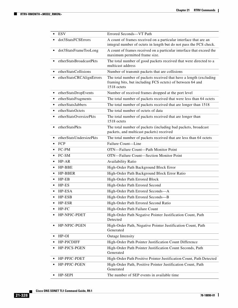
Chapter 21 RTRV CommandsRTRV-RMONTH-<MOD2_RMON>
• ESV Errored Seconds—VT Path
• dot3StatsFCSErrors A count of frames received on a particular interface that are an integral number of octets in length but do not pass the FCS check.
• dot3StatsFrameTooLong A count of frames received on a particular interface that exceed the maximum permitted frame size.
• etherStatsBroadcastPkts The total number of good packets received that were directed to a multicast address
• etherStatsCollisions Number of transmit packets that are collisions
• etherStatsCRCAlignErrors The total number of packets received that have a length (excluding framing bits, but including FCS octets) of between 64 and 1518 octets
• etherStatsDropEvents Number of received frames dropped at the port level
• etherStatsFragments The total number of packets received that were less than 64 octets
• etherStatsJabbers The total number of packets received that are longer than 1518
• etherStatsOctets The total number of octets of data
• etherStatsOversizePkts The total number of packets received that are longer than 1518 octets
• etherStatsPkts The total number of packets (including bad packets, broadcast packets, and multicast packets) received
• etherStatsUndersizePkts The total number of packets received that are less than 64 octets
• FCP Failure Count—Line
• FC-PM OTN—Failure Count—Path Monitor Point
• FC-SM OTN—Failure Count—Section Monitor Point
• HP-AR Availability Ratio
• HP-BBE High-Order Path Background Block Error
• HP-BBER High-Order Path Background Block Error Ratio
• HP-EB High-Order Path Errored Block
• HP-ES High-Order Path Errored Second
• HP-ESA High-Order Path Errored Seconds—A
• HP-ESB High-Order Path Errored Seconds—B
• HP-ESR High-Order Path Errored Second Ratio
• HP-FC High-Order Path Failure Count
• HP-NPJC-PDET High-Order Path Negative Pointer Justification Count, Path Detected
• HP-NPJC-PGEN High-Order Path, Negative Pointer Justification Count, Path Generated
• HP-OI Outage Intensity
• HP-PJCDIFF High-Order Path Pointer Justification Count Difference
• HP-PJCS-PGEN High-Order Path Pointer Justification Count Seconds, Path Generated
• HP-PPJC-PDET High-Order Path Positive Pointer Justification Count, Path Detected
• HP-PPJC-PGEN High-Order Path, Positive Pointer Justification Count, Path Generated
• HP-SEPI The number of SEP events in available time
21-328Cisco ONS SONET TL1 Command Guide, R9.1
78-18890-01

Chapter 21 RTRV CommandsRTRV-RMONTH-<MOD2_RMON>
• HP-SES High-Order Path Severely Errored Seconds
• HP-SESR High-Order Path Severely Errored Second Ratio
• HP-UAS High-Order Path Unavailable Seconds
• ifInBroadcastPkts Number of broadcast packets received since the last counter reset
• ifInDiscards The number of inbound packets
• ifInErrorBytePktss Receive Error Byte
• ifInErrors The number of inbound packets (or transmission units) that contained errors
• ifInFramingErrorPkts Receive Framing Error
• ifInJunkInterPkts Receive Interpacket Junk
• ifInMulticastPkts Number of multicast packets received since the last counter reset
• ifInOctets Number of bytes transmitted since the last counter reset
• ifInUcastPkts Number of unicast packets received since the last counter reset
• ifOutBroadcastPkts Number of broadcast packets transmitted
• ifOutDiscards The number of outbound packets
• ifOutErrors The number of outbound packets (or transmission units) that could not be transmitted because of errors
• ifOutMulticastPkts Number of multicast packets transmitted
• ifOutPayloadCrcErrors Received payload CRC errors
• ifOutUcastPkts Number of unicast packets transmitted
• IOS 8B10B—Idle Ordered Sets
• IPC Invalid Packet Count
• LBCL-AVG Average Laser Bias Current in microA
• LBCL-MAX Maximum Laser Bias Current in microA
• LBCL-MIN Minimum Laser Bias Current in microA
• LBCN Normalized Laser Bias Current for OC3-8
• LBCN-HWT Normalized Laser Bias Current—Higher Threshold
• LBCN-LWT Normalized Laser Bias Current—Lower Threshold
• LOSSL Loss of Signal Seconds—Line
• LP-BBE Low-Order Path Background Block Error
• LP-BBER Low-Order Path Background Block Error Ratio
• LP-EB Low-Order Path Errored Block
• LP-ES Low-Order Path Errored Second
• LP-ESA Low-Order Path Errored Seconds-A
• LP-ESB Low-Order Path Errored Seconds-B
• LP-ESR Low-Order Path Errored Second Ratio
• LP-FC Low-Order Path Failure Count
• LP-NPJC-DET Low-Order Negative Pointer Justification Count, Detected
• LP-NPJC-GEN Low Order Negative Pointer Justification Count, Generated
• LP-PPJC-DET Low-Order Positive Pointer Justification Count, Detected
• LP-PPJC-GEN Low-Order Positive Pointer Justification Count, Generated
• LP-SEP Low-Order Path Severely Errored Period
21-329Cisco ONS SONET TL1 Command Guide, R9.1
78-18890-01

Chapter 21 RTRV CommandsRTRV-RMONTH-<MOD2_RMON>
• LP-SEPI Low-Order Path Severely Errored Period Intensity
• LP-SES Low-Order Path Severely Errored
• LP-UAS Low-Order Path Unavailable Seconds
• MS-PSC Protection switch count
• MS-PSD Protection switch duration
• NIOS 8B10B—Non Idle Ordered Sets
• NPJC-PDET Negative Pointer Justification Count, Path Detected
• NPJC-PGEN Negative Pointer Justification Count, Path Generated
• OPR-AVG Average Receive Power in one tenth of a microwatt
• OPR-MAX Maximum Receive Power in one tenth of a microwatt
• OPR-MIN Minimum Receive Power in one tenth of a microwatt
• OPRN Normalized Optical Receive Power for OC3-8
• OPRN-MAX Maximum value for OPRN
• OPRN-MIN Minimum value for OPRN
• OPT-AVG Average Transmit Power in one tenth of a microwatt
• OPT-MAX Maximum Transmit Power in one tenth of a microwatt
• OPT-MIN Minimum Transmit Power in one tenth of a microwatt
• OPTN Normalized value for Optical Power Transmitted for the OC3-8 card
• OPTN-MAX Maximum value for OPTN
• OPTN-MIN Minimum value for OPTN
• OPWR-AVG Optical Power—Average Interval Value in one tenth of a dBm
• OPWR-MAX Optical Power—Maximum Interval Value in one tenth of a dBm
• OPWR-MIN Optical Power—Minimum Interval Value in one tenth of a dBm
• PPJC-PDET Positive Pointer Justification Count, Path Detected
• PPJC-PGEN Positive Pointer Justification Count, Path Generated
• PSC Protection Switching Count
• PSC-R Protection Switching Count—Ring
• PSC-S Protection Switching Count—Span
• PSC-W Protection Switching Count—Working
• PSD Protection Switching Duration
• PSD-R Protection Switching Duration—Ring
• PSD-S Protection Switching Duration—Span
• PSD-W Protection Switching Duration—Working
• SASCPP Severely Errored Framing/AIS Second—CP-Bit Path
• SASP Severely Errored Framing/AIS Seconds Path
• SEFS Severely Errored Framing Seconds
• SEFSP Severely Errored Framing Seconds—Path (DS3XM-12 DS1 PM count)
• SESCPP Severely Errored Second—CP-Bit Path
• SESL Severely Errored Second—Line
• SESNPFE Severely Errored Second—Network Path (DS3XM-12 DS1 PM count)
21-330Cisco ONS SONET TL1 Command Guide, R9.1
78-18890-01

Chapter 21 RTRV CommandsRTRV-RMONTH-<MOD2_RMON>
• SESP Severely Errored Second—Path
• SES-PM OTN—Severely Errored Second—Path
• SESR-PM OTN—Severely Errored Second Ratio—Path Monitor Point expressed as one tenth of a percentage
• SESR-SM OTN—Severely Errored Second Ratio—Section Monitor Point expressed as one tenth of a percentage
• SESS Severely Errored Second—Section
• SES-SM OTN—Severely Errored Second—Section Monitor Point
• SESV Severely Errored Second—VT Path
• UASCPP Unavailable Second—CP-Bit Path
• UASL Unavailable Second—Line
• UASNPFE Unavailable Second—Network Path (DS3XM-12 DS1 PM count)
• UASP Unavailable Second—Path
• UAS-PM OTN—Unavailable Second—Path Monitor Point
• UAS-SM OTN—Unavailable Second—Section Monitor Point
• UASV Unavailable Second—VT Path
• UNC-WORDS FEC—Uncorrectable Words
• VPC Valid Packet Count
<INTVL> The interval in seconds over which the data is sampled and compared with the rising and falling threshold. A valid value is any integer larger than or equal to 10 (seconds).
<INDEX> The index for the threshold created by the system in the RMON threshold table. INDEX is an integer.
<RISE> The rising threshold for the sampled statistic. A valid value is any integer.
<FALL> The falling threshold. A valid value is any integer smaller than the rising threshold. AID is an integer
<SAMPLE> The method of calculating the value to be compared to the thresholds. The parameter type is SAMPLE_TYPE, which describes how the data will be calculated during the sampling period
• ABSOLUTE Comparing directly
• DELTA Comparing with the current value of the selected variable subtracted from the last sample
<STARTUP> Dictates whether an event will generate if the first valid sample is greater than or equal to the rising threshold, less than or equal to the falling threshold, or both. The parameter type is STARTUP_TYPE, which indicates whether an event will be generated when the first valid sample is crossing the rising or falling threshold.
• FALLING Generates the event when the sample is smaller than or equal to the falling threshold.
• RISING Generates the event when the sample is greater than or equal to the rising threshold.
• RISING-OR-FALLING Generates the event when the sample is crossing the rising threshold or the falling threshold.
21-331Cisco ONS SONET TL1 Command Guide, R9.1
78-18890-01

Chapter 21 RTRV CommandsRTRV-ROLL-<MOD_PATH>
21.104 RTRV-ROLL-<MOD_PATH>(Cisco ONS 15454, 15327, 15600, 15310) The Retrieve Roll for STS1, STS12C, STS18C, STS192C, STS24C, STS36C, STS3C, STS48C, STS96C, STS6C, STS9C, VC11, VC12, VC3, VT1, or VT2 (RTRV-ROLL-<MOD_PATH>) command retrieves roll data parameters.
Usage Guidelines See Table 28-1 on page 1 for supported modifiers by platform.
Category Bridge and Roll
Security Retrieve
Input Format RTRV-ROLL-<MOD_PATH>:[<TID>]:<SRC>:<CTAG>;
Input Example RTRV-ROLL-STS1:CISCO:STS-1-1-1:6;
Input Parameters
Output Format SID DATE TIMEM CTAG COMPLD “<FROM>,<TO>:RFROM=<RFROM>,RTO=<RTO>,[RMODE=<RMODE>], VLDSIG=<VLDSIG>”;
Output Example TID-000 1998-06-20 14:30:00M 001 COMPLD “STS-1-1-1,STS-2-1-1:RFROM=STS-2-1-1,RTO=STS-3-1-1,RMODE=AUTO,VLDSIG=N”;
Output Parameters
<SRC> Source access identifier from the “26.11 CrossConnectId1” section on page 26 (except VCM and FACILITY). Roll path (STS or VT).
<FROM> One of the termination points (legs) of the existing cross-connection. AID from the “26.11 CrossConnectId1” section on page 26 (except VCM and FACILITY).
<TO> One of the termination points (legs) of the existing cross-connection. AID from the “26.11 CrossConnectId1” section on page 26 (except VCM and FACILITY).
<RFROM> The termination point of the existing cross-connect that is to be rolled. AID from the “26.11 CrossConnectId1” section on page 26 (except VCM and FACILITY).
21-332Cisco ONS SONET TL1 Command Guide, R9.1
78-18890-01

Chapter 21 RTRV CommandsRTRV-ROUTE
21.105 RTRV-ROUTE(Cisco ONS 15454, 15327, 15600, 15310) The Retrieve Route (RTRV-ROUTE) command retrieves static routes.
Usage Guidelines • There is no DNS service available on the node. Only numeric IP addresses will be accepted.
• The optional parameters DESTIP, IPMASK, NXTHOP, and COST are used to filter the retrieved static routes. In the absence of any optional parameter, all the static routes on the node will be retrieved.
Category System
Security Retrieve
Input Format RTRV-ROUTE:[<TID>]::<CTAG>::[<DESTIP>],[<IPMASK>],[<NXTHOP>],[<COST>];
Input Example RTRV-ROUTE:CISCO::123::10.64.72.57,255.255.255.0,10.64.10.1,200;
Input Parameters
<RTO> The termination point that will become a leg of the new cross-connection. AID from the “26.11 CrossConnectId1” section on page 26 (except VCM and FACILITY).
<RMODE> (Optional) The rolling mode of operation. The parameter type is RMODE, which specifies the roll mode.
• AUTO Automatic. When a valid signal is available, the roll under AUTO mode will automatically delete the previous end-point.
• MAN Manual. Enter the corresponding delete roll/bulkroll command to delete the previous end-point.
<VLDSIG> Shows whether or not the roll has received a valid signal. VLDSIG is Y if the signal is valid and N if it is not. The parameter type is ON_OFF (disable or enable an attribute).
• N Disable an attribute.
• Y Enable an attribute.
<DESTIP> Destination tip. DESTIP is a string. A null value is equivalent to ALL.
<IPMASK> IP mask. IPMASK is a string. A null value is equivalent to ALL.
<NXTHOP> Next hop. NXTHOP is a string. A null value is equivalent to ALL.
<COST> Unsigned integer. Valid range is from 1 to 32,797. A null value is equivalent to ALL.
21-333Cisco ONS SONET TL1 Command Guide, R9.1
78-18890-01

Chapter 21 RTRV CommandsRTRV-ROUTE-GRE
Output Format SID DATE TIMEM CTAG COMPLD “,:<DESTIP>,<IPMASK>,<NXTHOP>,<COST>”;
Output Example TID-000 1998-06-20 14:30:00M 001 COMPLD “,:\“10.64.72.57\”,\“255.255.255.0\”,\“10.64.10.1\”,200”;
Output Parameters
21.106 RTRV-ROUTE-GRE(Cisco ONS 15454, 15327, 15600, 15310) The Retrieve Route Generic Routing Encapsulation (RTRV-ROUTE-GRE) command displays the existing GRE tunnels.
Usage Guidelines None
Category System
Security Retrieve
Input Format RTRV-ROUTE-GRE:[<TID>]::<CTAG>[::::];
Input Example RTRV-ROUTE-GRE:CISCO::123;
Input Parameters None that require description
Output Format SID DATE TIMEM CTAG COMPLD “,:IPADDR=<IPADDR>,IPMASK=<IPMASK>,NSAP=<NSAP>,COST=<COST>”;
<DESTIP> Destination tip. DESTIP is a string.
<IPMASK> IP mask. IPMASK is a string.
<NXTHOP> Next hop. NXTHOP is a string.
<COST> Cost. COST is a string.
21-334Cisco ONS SONET TL1 Command Guide, R9.1
78-18890-01

Chapter 21 RTRV CommandsRTRV-SHELFSTAT
Output Example TID-000 1998-06-20 14:30:00M 001 COMPLD “,:IPADDR=10.64.72.57,IPMASK=255.255.255.0, NSAP=39840F80FFFFFF0000DDDDAA000010CFB4910200,COST=110”;
Output Parameters
21.107 RTRV-SHELFSTAT(Cisco ONS 15310-CL, Cisco ONS 15310-MA, Cisco ONS 15454, and Cisco ONS 15600) The RTRV-SHELFSTAT command retrieves and reports the temperature and voltage of the shelf.
Note The input voltage is displayed only when the customer access panel (CAP2) card is installed in the ONS 15600 chassis.
Usage Guidelines None
Category Equipment
Security Retrieve
Input Format RTRV-SHELFSTAT:[<TID>]:<AID>:<CTAG>;
Input Example RTRV-SHELFSTAT:CISCO454::1;
Output Format SID DATE TIMEM CTAG COMPLD"AID:AIDTYPE,TEMPERATURE= <TEMPERATURE>,VOLTAGEA= <VOLTAGEA>,VOLTAGEB= <VOLTAGEB>[,VOLTAGEC= <VOLTAGEC>,VOLTAGED= <VOLTAGED>]";
<IPADDR> IP address of the tunnel endpoint. IPADDR is a string.
<IPMASK> Subnet mask for the tunnel endpoint. IPMASK is a string.
<NSAP> NSAP address for the tunnel endpoint. NSAP is a string.
<COST> Routing cost associated with the tunnel. COST is an integer.
21-335Cisco ONS SONET TL1 Command Guide, R9.1
78-18890-01
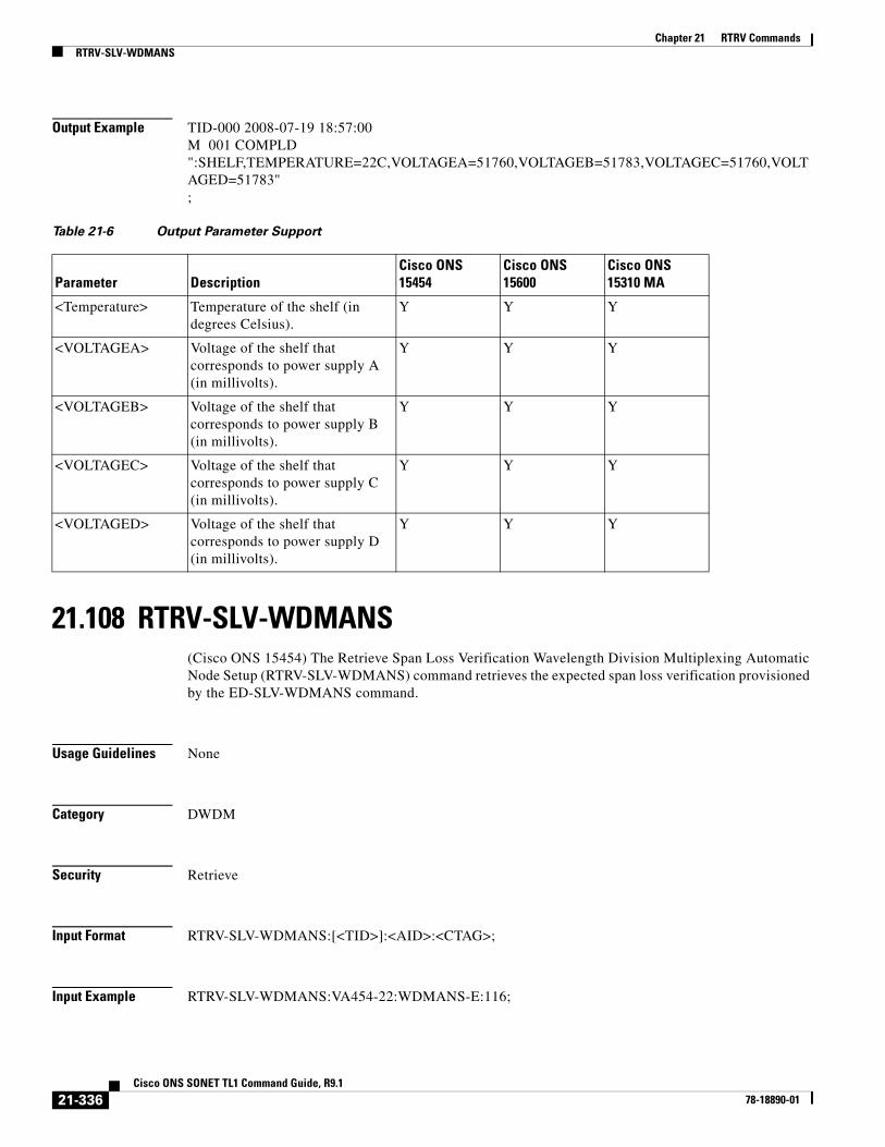
Chapter 21 RTRV CommandsRTRV-SLV-WDMANS
Output Example TID-000 2008-07-19 18:57:00M 001 COMPLD":SHELF,TEMPERATURE=22C,VOLTAGEA=51760,VOLTAGEB=51783,VOLTAGEC=51760,VOLTAGED=51783";
21.108 RTRV-SLV-WDMANS(Cisco ONS 15454) The Retrieve Span Loss Verification Wavelength Division Multiplexing Automatic Node Setup (RTRV-SLV-WDMANS) command retrieves the expected span loss verification provisioned by the ED-SLV-WDMANS command.
Usage Guidelines None
Category DWDM
Security Retrieve
Input Format RTRV-SLV-WDMANS:[<TID>]:<AID>:<CTAG>;
Input Example RTRV-SLV-WDMANS:VA454-22:WDMANS-E:116;
Table 21-6 Output Parameter Support
Parameter DescriptionCisco ONS 15454
Cisco ONS 15600
Cisco ONS 15310 MA
<Temperature> Temperature of the shelf (in degrees Celsius).
Y Y Y
<VOLTAGEA> Voltage of the shelf that corresponds to power supply A (in millivolts).
Y Y Y
<VOLTAGEB> Voltage of the shelf that corresponds to power supply B (in millivolts).
Y Y Y
<VOLTAGEC> Voltage of the shelf that corresponds to power supply C (in millivolts).
Y Y Y
<VOLTAGED> Voltage of the shelf that corresponds to power supply D (in millivolts).
Y Y Y
21-336Cisco ONS SONET TL1 Command Guide, R9.1
78-18890-01

Chapter 21 RTRV CommandsRTRV-STS
Input Parameters
Output Format SID DATE TIMEM CTAG COMPLD “<AID>::[HIGHSLVEXP=<HIGHSLVEXP>],[LOWSLVEXP=<LOWSLVEXP>], [SLVACT=<SLVACT>],[RESOLUTION=<RESOLUTION>]”;
Output Example TID-000 1998-06-20 14:30:00M 001 COMPLD “WDMANS-E::HIGHSLVEXP=10.0,LOWSLVEXP=5.0,SLVACT=10.0,RESOLUTION=1.0:”;
Output Parameters
21.109 RTRV-STS(Cisco ONS 15454, 15327, 15600, 15310) The Retrieve Synchronous Transport Signal (RTRV-STS) command retrieves the attributes associated with an STS path based on the granularity level of NE/SLOT-specific STSs.
Usage Guidelines • Supported AIDs are ALL, SLOT-N (N=1,2,...,ALL), STS-<SLOT>[-<PORT>]-<STS NUMBER>.
• The SFBER, SDBER, RVRTV, RVTM, SWPDIP, HOLDOFFTIMER, and UPSRPTHSTATE parameters only apply to path protection.
• The path trace message is a 64-character string including the terminating CR (carriage return) and LF (line feed) that is transported in the J1 byte of the SONET STS Path overhead.
• The EXPTRC indicates that the contents of the expected incoming path trace are provisioned by the user in the ED-STS_PATH command. The TRC indicates the contents of the outgoing path trace message. The INCTRC indicates the contents of the incoming path trace message.
• The path trace mode has three modes: OFF, MANUAL, and AUTO. The mode defaults to OFF. The MANUAL mode compares the received string with the user entered expected string. The AUTO mode compares the present received string with an expected string set to a previously received string. If there is a mismatch, the TIM-P alarm is raised. When the path trace mode is in OFF mode, there is no path trace processing, and all the alarm and state conditions are reset.
<AID> Access identifier from the “26.32 WDMANS” section on page 53.
<AID> Access identifier from the “26.32 WDMANS” section on page 53.
<HIGHSLVEXP> (Optional) The high range value of the expected span loss verification. HIGHSLVEXP is a float.
<LOWSLVEXP> (Optional) The low range value of the expected span loss verification. LOWSLVEXP is a float.
<SLVACT> (Optional) The value of the calculated span loss verification. SLVACT is a float.
<RESOLUTION> (Optional) The value of the resolution applied to the calculated span loss verification. RESOLUTION is a float.
21-337Cisco ONS SONET TL1 Command Guide, R9.1
78-18890-01
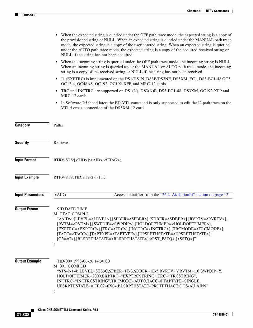
Chapter 21 RTRV CommandsRTRV-STS
• When the expected string is queried under the OFF path trace mode, the expected string is a copy of the provisioned string or NULL. When an expected string is queried under the MANUAL path trace mode, the expected string is a copy of the user entered string. When an expected string is queried under the AUTO path trace mode, the expected string is a copy of the acquired received string or NULL if the string has not been acquired.
• When the incoming string is queried under the OFF path trace mode, the incoming string is NULL. When an incoming string is queried under the MANUAL or AUTO path trace mode, the incoming string is a copy of the received string or NULL if the string has not been received.
• J1 (EXPTRC) is implemented on the DS1/DS1N, DS3E/DS3NE, DS3XM, EC1, DS3-EC1-48 OC3, OC12-4, OC48AS, OC192, OC192-XFP, and MRC-12 cards.
• TRC and INCTRC are supported on DS1(N), DS3(N)E, DS3-EC1-48, DS3XM, OC192-XFP and MRC-12 cards.
• In Software R5.0 and later, the ED-VT1 command is only supported to edit the J2 path trace on the VT1.5 cross-connection of the DS3XM-12 card.
Category Paths
Security Retrieve
Input Format RTRV-STS:[<TID>]:<AID>:<CTAG>;
Input Example RTRV-STS:TID:STS-2-1-1:1;
Input Parameters
Output Format SID DATE TIMEM CTAG COMPLD “<AID>::[LEVEL=<LEVEL>],[SFBER=<SFBER>],[SDBER=<SDBER>],[RVRTV=<RVRTV>], [RVTM=<RVTM>],[SWPDIP=<SWPDIP>],[HOLDOFFTIMER=<HOLDOFFTIMER>], [EXPTRC=<EXPTRC>],[TRC=<TRC>],[INCTRC=<INCTRC>],[TRCMODE=<TRCMODE>], [TACC=<TACC>],[TAPTYPE=<TAPTYPE>],[UPSRPTHSTATE=<UPSRPTHSTATE>], [C2=<C>],[BLSRPTHSTATE=<BLSRPTHSTATE>]:<PST_PSTQ>,[<SSTQ>]”;
Output Example TID-000 1998-06-20 14:30:00M 001 COMPLD “STS-2-1-4::LEVEL=STS3C,SFBER=1E-3,SDBER=1E-5,RVRTV=Y,RVTM=1.0,SWPDIP=Y, HOLDOFFTIMER=2000,EXPTRC=“EXPTRCSTRING”,TRC=“TRCSTRING”, INCTRC=“INCTRCSTRING”,TRCMODE=AUTO,TACC=8,TAPTYPE=SINGLE, UPSRPTHSTATE=ACT,C2=0X04,BLSRPTHSTATE=PROTPTHACT:OOS-AU,AINS”;
<AID> Access identifier from the “26.2 AidUnionId” section on page 12.
21-338Cisco ONS SONET TL1 Command Guide, R9.1
78-18890-01

Chapter 21 RTRV CommandsRTRV-STS
Output Parameters <AID> Access identifier from the “26.2 AidUnionId” section on page 12.
<LEVEL> (Optional) The rate of the cross-connect. Applicable only to STS paths in SONET. The parameter type is STS_PATH, which is the modifier for some STS commands.
• STS1 Synchronous Transport Signal level 1 (51 Mbps)
• STS12C Synchronous Transport Signal level 12 Concatenated (622 Mbps)
• STS18C Synchronous Transport Signal level 18 Concatenated (933 Mbps)
• STS192C Synchronous Transport Signal level 192 (9952 Mbps)
• STS24C Synchronous Transport Signal level 24 Concatenated (1240 Mbps)
• STS36C Synchronous Transport Signal level 36 Concatenated (1866 Mbps)
• STS3C Synchronous Transport Signal level 3 Concatenated (155 Mbps)
• STS48C Synchronous Transport Signal level 48 Concatenated (2488 Mbps)
• STS6C Synchronous Transport Signal level 3 Concatenated (310 Mbps)
• STS9C Synchronous Transport Signal level 9 Concatenated (465 Mbps)
<SFBER> (Optional) An STS path SFBER that applies only to path protection and only to STS-level paths in SONET. Defaults to 1E-4. The parameter type is SF_BER, which is the threshold for declaring signal failure on a facility or path.
• 1E-3 SFBER is 1E-3.
• 1E-4 SFBER is 1E-4.
• 1E-5 SFBER is 1E-5.
<SDBER> (Optional) An STS path SDBER that applies only to path protection and only to STS-level paths in SONET. Defaults to 1E-6. The parameter type is SD_BER, which is the threshold for declaring signal degrade on a facility or path.
• 1E-5 SDBER is 1E-5.
• 1E-6 SDBER is 1E-6.
• 1E-7 SDBER is 1E-7.
• 1E-8 SDBER is 1E-8.
• 1E-9 SDBER is 1E-9.
<RVRTV> (Optional) Revertive mode. The value Y indicates that protection switching system reverts service to the original line after restoration. The value N indicates that protection switching system does not revert service to the original line after restoration. RVRTV is applicable only for 1+1 protection switching. Null defaults to N. Only applies to path protection. The parameter type is ON_OFF (disable or enable an attribute).
• N Does not revert service to original line after restoration.
• Y Reverts service to original line after restoration.
<RVTM> Revertive time. RVTM is not allowed to be set while RVRTV is N. Only applies to path protection. The parameter type is REVERTIVE_TIME.
• 0.5 to 12.0 Revertive time is 0.5 to 12.0 minutes.
21-339Cisco ONS SONET TL1 Command Guide, R9.1
78-18890-01

Chapter 21 RTRV CommandsRTRV-STS
<SWPDIP> (Optional) Switch on PDI-P. Applicable only to STS-level paths in SONET (STSn). The parameter type is ON_OFF (disable or enable an attribute).
• N Disable an attribute.
• Y Enable an attribute.
<HOLDOFFTIMER> (Optional) Hold off timer. HOLDOFFTIMER is an integer.
<EXPTRC> (Optional) Expected path trace content. A 64-character ASCII string including the terminating CR (carriage return) and LF (line feed). Indicates the expected path trace message (J1) contents. Applicable only to STS-Level Paths in SONET. Defaults to null when path protection path is created.
<TRC> (Optional) The path trace message to be transmitted. The trace byte (J1) continuously transmits a 64-byte, fixed length ASCII string, one byte at a time. A null value defaults to the NE transmitting 62 null characters (hex 00) and CR and LF. A null value defaults to the NE transmitting null characters (Hex 00). Applicable to STS-level paths in SONET (STSn). TRC is a string.
<INCTRC> (Optional) Identifies the incoming path trace message contents. Can be any combination of 64-characters. Applicable only to STS-level paths in SONET. Defaults to null when a path protection path is created. INCTRC is a string.
<TRCMODE> (Optional) Path trace mode. Applicable only to STS-level Paths in SONET (STSn). Defaults to the OFF mode. The parameter type is TRCMODE (trace mode).
• AUTO Use the previously received path trace string as the expected string. Not applicable to MXP/TXP cards.
• AUTO-NO-AIS Use the previously received path trace string as the expected string and do not turn on AIS and RDI if TIM-P is detected.
• MAN Use the provisioned expected string as the expected string.
• MAN-NO-AIS Use the provisioned expected string as the expected string and do not turn on AIS and RDI if TIM-P is detected.
• OFF Turn off path trace capability. Nothing will be reported.
<TACC> (Optional) Indicates whether the digroup being provisioned is to be used as a test access digroup. Default is N. TACC is an integer.
<TAPTYPE> (Optional) TAP type. The parameter type is TAPTYPE, which is the test access point type.
• DUAL Dual FAD
• SINGLE Single FAD
<UPSRPTHSTATE> (Optional) Indicates whether a given AID is the working or standby path of a path protection cross-connect. The parameter type is STATUS, which is the status of the unit in the protection pair.
• ACT The entity is the active unit in the shelf.
• NA Status is unavailable.
• STBY The entity is the standby unit in the shelf.
<C> (Optional) The C2 byte hex code. Applicable only to STS-level paths in SONET (STSn). The parameter type is C2_BYTE, which is the C2 byte hex code.
21-340Cisco ONS SONET TL1 Command Guide, R9.1
78-18890-01
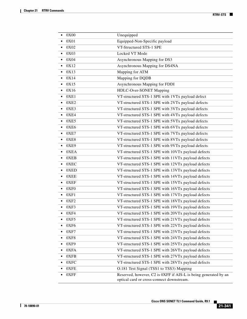
Chapter 21 RTRV CommandsRTRV-STS
• 0X00 Unequipped
• 0X01 Equipped-Non-Specific payload
• 0X02 VT-Structured STS-1 SPE
• 0X03 Locked VT Mode
• 0X04 Asynchronous Mapping for DS3
• 0X12 Asynchronous Mapping for DS4NA
• 0X13 Mapping for ATM
• 0X14 Mapping for DQDB
• 0X15 Asynchronous Mapping for FDDI
• 0X16 HDLC-Over-SONET Mapping
• 0XE1 VT-structured STS-1 SPE with 1VTx payload defect
• 0XE2 VT-structured STS-1 SPE with 2VTx payload defects
• 0XE3 VT-structured STS-1 SPE with 3VTx payload defects
• 0XE4 VT-structured STS-1 SPE with 4VTx payload defects
• 0XE5 VT-structured STS-1 SPE with 5VTx payload defects
• 0XE6 VT-structured STS-1 SPE with 6VTx payload defects
• 0XE7 VT-structured STS-1 SPE with 7VTx payload defects
• 0XE8 VT-structured STS-1 SPE with 8VTx payload defects
• 0XE9 VT-structured STS-1 SPE with 9VTx payload defects
• 0XEA VT-structured STS-1 SPE with 10VTx payload defects
• 0XEB VT-structured STS-1 SPE with 11VTx payload defects
• 0XEC VT-structured STS-1 SPE with 12VTx payload defects
• 0XED VT-structured STS-1 SPE with 13VTx payload defects
• 0XEE VT-structured STS-1 SPE with 14VTx payload defects
• 0XEF VT-structured STS-1 SPE with 15VTx payload defects
• 0XF0 VT-structured STS-1 SPE with 16VTx payload defects
• 0XF1 VT-structured STS-1 SPE with 17VTx payload defects
• 0XF2 VT-structured STS-1 SPE with 18VTx payload defects
• 0XF3 VT-structured STS-1 SPE with 19VTx payload defects
• 0XF4 VT-structured STS-1 SPE with 20VTx payload defects
• 0XF5 VT-structured STS-1 SPE with 21VTx payload defects
• 0XF6 VT-structured STS-1 SPE with 22VTx payload defects
• 0XF7 VT-structured STS-1 SPE with 23VTx payload defects
• 0XF8 VT-structured STS-1 SPE with 24VTx payload defects
• 0XF9 VT-structured STS-1 SPE with 25VTx payload defects
• 0XFA VT-structured STS-1 SPE with 26VTx payload defects
• 0XFB VT-structured STS-1 SPE with 27VTx payload defects
• 0XFC VT-structured STS-1 SPE with 28VTx payload defects
• 0XFE O.181 Test Signal (TSS1 to TSS3) Mapping
• 0XFF Reserved, however, C2 is 0XFF if AIS-L is being generated by an optical card or cross-connect downstream.
21-341Cisco ONS SONET TL1 Command Guide, R9.1
78-18890-01

Chapter 21 RTRV CommandsRTRV-SYNCN
21.110 RTRV-SYNCN(Cisco ONS 15454, 15327, 15600, 15310) The Retrieve Synchronization command retrieves the synchronization reference list used to determine the sources for the NE's reference clock and the BITS output clock. For each clock, up to three synchronization sources can be specified (for example, PRIMARY, SECOND, THIRD).
Usage Guidelines • To retrieve/set the timing mode, SSM message Set or Quality of RES information, use the RTRV-NE-SYNCN and ED-NE-SYNCN commands.
• The output example shown here is under line timing mode.
<BLSRPTHSTATE> (Optional) The BLSR path state only if the port is on the BLSR. Applicable only to STS-level paths in SONET (STSn). The parameter type is BLSR_PTH_STATE, which is the BLSR path state only if the port is on the BLSR.
• PCAPTHACT Indicates the BLSR is not switched and its PCA path is in the active state.
• PCAPTHSTB Indicates the BLSR is switched and its PCA path is in the standby state.
• PROTPTHACT Indicates the BLSR is switched and its protection path is in the active state.
• WKGPTHACT Indicates the BLSR is not switched and its working path is in the active state.
• WKGPTHSTB Indicates the BLSR is switched and its working path is in the standby state.
<PST_PSTQ> Administrative state in the PST_PSTQ format. The parameter type is PST_PSTQ, which is the service state of the entity described by the SST and PSTQ.
• IS-NR In Service and Normal
• OOS-AU Out of Service and Autonomous
• OOS-AUMA Out of Service and Autonomous Management
• OOS-MA Out of Service and Management
<SSTQ> (Optional) Secondary state of the entity. The parameter type is SST, which provides additional information pertaining to PST and PSTQ.
• AINS Automatic In-Service
• DSBLD Disabled
• LPBK Loopback
• MEA Mismatch of Equipment
• MT Maintenance
• OOG Out of Group
• SWDL Software Download
• UAS Unassigned
• UEQ Unequipped
21-342Cisco ONS SONET TL1 Command Guide, R9.1
78-18890-01

Chapter 21 RTRV CommandsRTRV-SYNCN
Category Synchronization
Security Retrieve
Input Format RTRV-SYNCN:[<TID>]:<AID>:<CTAG>[::::];
Input Example RTRV-SYNCN:BOYES:SYNC-NE:234;
Input Parameters
Output Format SID DATE TIMEM CTAG COMPLD “<AID>:<REF>,<REFVAL>,[<QREF>],[<STATUS>],[<PROTECTSTATUS>]”;
Output Example TID-000 1998-06-20 14:30:00M 001 COMPLD “SYNC-NE:PRI,FAC-1-2,WORK,ACT,PRS”;
Output Parameters
<AID> Access identifier from the “26.28 SYNC_REF” section on page 51.
<AID> Access identifier from the “26.28 SYNC_REF” section on page 51.
<REF> Rank of synchronization reference. Access identifier from the “26.29 SYNCSW” section on page 51.
<REFVAL> Value of a synchronization reference. “26.27 SYN_SRC” section on page 50.
<QREF> (Optional) Indicates whether the working or protect card (in a protection group) provides timing. This parameter has no significance if the reference source is BITS or INTERNAL and is left blank. The parameter type is SYNC_CLOCK_REF_QUALITY_LEVEL, which is the clock source quality level for SONET.
• DUS Do Not Use For Synchronization
• PRS Primary Reference Source, Stratum 1 Traceable
• RES Reserved For Network Synchronization Use
• SMC SONET Minimum Clock Traceable
• SSM-FAILED Incoming timing signal cannot be used for synchronization as it has an alarm like LOS, LOF, AIS-L.
• ST2 Stratum 2 Traceable
• ST3 Stratum 3 Traceable
• ST3E Stratum 3E Traceable
21-343Cisco ONS SONET TL1 Command Guide, R9.1
78-18890-01

Chapter 21 RTRV CommandsRTRV-T1
21.111 RTRV-T1(Cisco ONS 15310-CL, Cisco ONS 15310-MA, and Cisco ONS 15454) The Retrieve T1 Facility (RTRV-T1) command retrieves the DS-1 facilities configuration.
Usage Guidelines • The parameters SYNCMAP, ADMSSM, VTMAP, INHFELPBK, AND PROVIDESYNC are only displayed on the DS1/E1-56 card (ONS 15454).
• The parameters BERTMODE, BERTPATTERN, BERTERRCOUNT, BERTERRRATE, and BERTSYNCSTATUS apply only to DS1/E1-56 and DS3XM-12 cards.
• BERT is implemented on a single port.
• For ONS 15310-CL, SENDDUS and RETIME parameters are optional and defaults to N. SENDDUS and RETIME are not supported on the ONS 15454.
Category Ports
Security Retrieve
Input Format RTRV-T1:[<TID>]:<AID>:<CTAG>[::::];
Input Example RTRV-T1:TID:FAC-2-1:1223;
Input Parameters
• ST4 Stratum 4 Traceable
• STU Synchronized, Traceability Unknown
• TNC Transit Node Clock (2nd Generation Only)
<STATUS> (Optional) Status. The parameter type is STATUS, which is the status of the unit in the protection pair.
• ACT The entity is the active unit in the shelf.
• NA Status is unavailable.
• STBY The entity is the standby unit in the shelf.
<PROTECTSTATUS> (Optional) Applicable to 1+1. Designates the role of the entity in the protection group. Either it is the working or the protect entity. Not applicable to the ONS 15600 platform. The parameter type is SIDE, which is the role the unit is playing in the protection group.
• PROT The entity is a protection unit in the protection group.
• WORK The entity is a working unit in the protection group.
<AID> Access identifier from the “26.15 FACILITY” section on page 35.
21-344Cisco ONS SONET TL1 Command Guide, R9.1
78-18890-01

Chapter 21 RTRV CommandsRTRV-T1
Output Format SID DATE TIMEM CTAG COMPLD“<AID>::[LINECDE=<LINECDE>],[FMT=<FMT>],[LBO=<LBO>],[TACC=<TAP>],[TAPTYPE=<TAPTYPE>],[SOAK=<SOAK>],[SOAKLEFT=<SOAKLEFT>],[SFBER=<SFBER>],[SDBER=<SDBER>],[NAME=<NAME>],[SYNCMSG=<SYNCMSG>],[SENDDUS=<SENDDUS>],[RETIME=<RETIME>],[AISONLPBK=<AISONLPBK>],[AISVONAIS=<AISVONAIS>],[AISONLOF=<AISONLOF>],[MODE=<MODE>],[SYNCMAP=<SYNCMAP>],[ADMSSM=<ADMSSM>],[PROVIDESYNC=<PROVIDESYNC>],[VTMAP=<VTMAP>],[INHFELPBK=<INHFELPBK>],[BERTMODE=<BERTMODE>],[BERTPATTERN=<BERTPATTERN>],[BERTERRCOUNT=<BERTERRCOUNT>],[BERTERRRATE=<BERTERRRATE>],[BERTSYNCSTATUS=<BERTSYNCSTATUS>]:<PST>,[<SST>]”;
Output Example TID-000 1998-06-20 14:30:00M 001 COMPLD"FAC-2-1::LINECDE=AMI,FMT=ESF,LBO=0-131,TACC=8,TAPTYPE=DUAL,SOAK=52,SOAKLEFT=12-25,SFBER=1E-4,SDBER=1E-7,NAME=\"T1 PORT",SYNCMSG=Y,SENDDUS=Y,RETIME=Y,AISONLPBK=ALL,AISVONAIS=Y,AISONLOF=Y,MODE=FDL,SYNCMAP=ASYNC,ADMSSM=STU,PROVIDESYNC=N,VTMAP=GR253,INHFELPBK=N,BERTMODE=NONE,BERTPATTERN=NONE,BERTERRCOUNT=,BERTERRRATE=NONE,BERTSYNCSTATUS=N:OOS-AU,AINS";
Output Parameters <AID> Access identifier from the “26.15 FACILITY” section on page 35.
<LINECDE> (Optional) Line code. The parameter type is LINE_CODE.
• AMI Line code value is AMI.
• B8ZS Line code value is B8ZS.
<FMT> (Optional) Digital signal frame format. The parameter type is FRAME_FORMAT, which is the frame format for a T1 port.
• D4 (Default) Frame format is D4.
• ESF Frame format is ESF.
• UNFRAMED Frame format is unframed.
<LBO> (Optional) Line buildout settings. LBP is an integer. The parameter type is LINE_BUILDOUT.
• 0–131 Line buildout range is 0–131
• 132–262 Line buildout range is 132–262
• 263–393 Line buildout range is 263–393
• 394–524 Line buildout range is 394–524
• 525–655 Line buildout range is 525–655
<TAP> (Optional) Defines the STS as a test access port with a selected unique TAP number. The TAP number is within a range of 0, 1 to 999. When TACC is 0 (zero), the TAP is deleted. Default is N.
<TAPTYPE> (Optional) TAP type. The parameter type is TAPTYPE, which is the test access point type.
• DUAL Dual FAD
21-345Cisco ONS SONET TL1 Command Guide, R9.1
78-18890-01
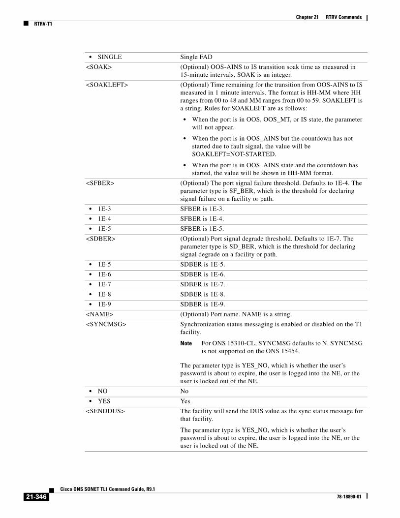
Chapter 21 RTRV CommandsRTRV-T1
• SINGLE Single FAD
<SOAK> (Optional) OOS-AINS to IS transition soak time as measured in 15-minute intervals. SOAK is an integer.
<SOAKLEFT> (Optional) Time remaining for the transition from OOS-AINS to IS measured in 1 minute intervals. The format is HH-MM where HH ranges from 00 to 48 and MM ranges from 00 to 59. SOAKLEFT is a string. Rules for SOAKLEFT are as follows:
• When the port is in OOS, OOS_MT, or IS state, the parameter will not appear.
• When the port is in OOS_AINS but the countdown has not started due to fault signal, the value will be SOAKLEFT=NOT-STARTED.
• When the port is in OOS_AINS state and the countdown has started, the value will be shown in HH-MM format.
<SFBER> (Optional) The port signal failure threshold. Defaults to 1E-4. The parameter type is SF_BER, which is the threshold for declaring signal failure on a facility or path.
• 1E-3 SFBER is 1E-3.
• 1E-4 SFBER is 1E-4.
• 1E-5 SFBER is 1E-5.
<SDBER> (Optional) Port signal degrade threshold. Defaults to 1E-7. The parameter type is SD_BER, which is the threshold for declaring signal degrade on a facility or path.
• 1E-5 SDBER is 1E-5.
• 1E-6 SDBER is 1E-6.
• 1E-7 SDBER is 1E-7.
• 1E-8 SDBER is 1E-8.
• 1E-9 SDBER is 1E-9.
<NAME> (Optional) Port name. NAME is a string.
<SYNCMSG> Synchronization status messaging is enabled or disabled on the T1 facility.
Note For ONS 15310-CL, SYNCMSG defaults to N. SYNCMSG is not supported on the ONS 15454.
The parameter type is YES_NO, which is whether the user’s password is about to expire, the user is logged into the NE, or the user is locked out of the NE.
• NO No
• YES Yes
<SENDDUS> The facility will send the DUS value as the sync status message for that facility.
The parameter type is YES_NO, which is whether the user’s password is about to expire, the user is logged into the NE, or the user is locked out of the NE.
21-346Cisco ONS SONET TL1 Command Guide, R9.1
78-18890-01
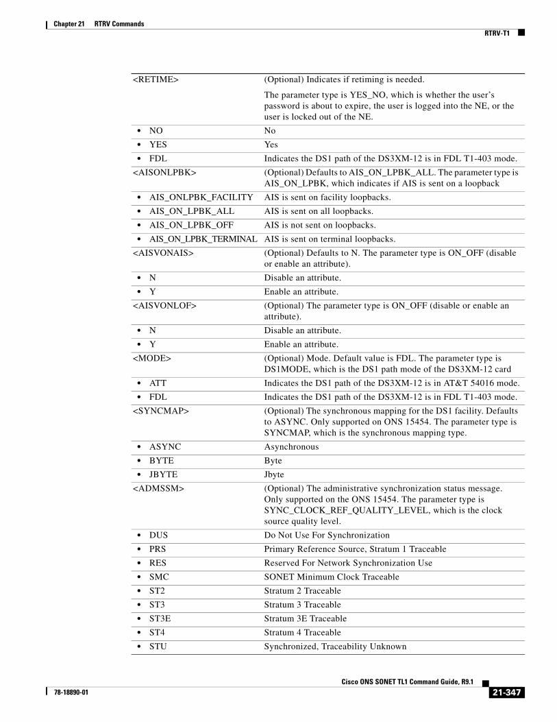
Chapter 21 RTRV CommandsRTRV-T1
<RETIME> (Optional) Indicates if retiming is needed.
The parameter type is YES_NO, which is whether the user’s password is about to expire, the user is logged into the NE, or the user is locked out of the NE.
• NO No
• YES Yes
• FDL Indicates the DS1 path of the DS3XM-12 is in FDL T1-403 mode.
<AISONLPBK> (Optional) Defaults to AIS_ON_LPBK_ALL. The parameter type is AIS_ON_LPBK, which indicates if AIS is sent on a loopback
• AIS_ONLPBK_FACILITY AIS is sent on facility loopbacks.
• AIS_ON_LPBK_ALL AIS is sent on all loopbacks.
• AIS_ON_LPBK_OFF AIS is not sent on loopbacks.
• AIS_ON_LPBK_TERMINAL AIS is sent on terminal loopbacks.
<AISVONAIS> (Optional) Defaults to N. The parameter type is ON_OFF (disable or enable an attribute).
• N Disable an attribute.
• Y Enable an attribute.
<AISVONLOF> (Optional) The parameter type is ON_OFF (disable or enable an attribute).
• N Disable an attribute.
• Y Enable an attribute.
<MODE> (Optional) Mode. Default value is FDL. The parameter type is DS1MODE, which is the DS1 path mode of the DS3XM-12 card
• ATT Indicates the DS1 path of the DS3XM-12 is in AT&T 54016 mode.
• FDL Indicates the DS1 path of the DS3XM-12 is in FDL T1-403 mode.
<SYNCMAP> (Optional) The synchronous mapping for the DS1 facility. Defaults to ASYNC. Only supported on ONS 15454. The parameter type is SYNCMAP, which is the synchronous mapping type.
• ASYNC Asynchronous
• BYTE Byte
• JBYTE Jbyte
<ADMSSM> (Optional) The administrative synchronization status message. Only supported on the ONS 15454. The parameter type is SYNC_CLOCK_REF_QUALITY_LEVEL, which is the clock source quality level.
• DUS Do Not Use For Synchronization
• PRS Primary Reference Source, Stratum 1 Traceable
• RES Reserved For Network Synchronization Use
• SMC SONET Minimum Clock Traceable
• ST2 Stratum 2 Traceable
• ST3 Stratum 3 Traceable
• ST3E Stratum 3E Traceable
• ST4 Stratum 4 Traceable
• STU Synchronized, Traceability Unknown
21-347Cisco ONS SONET TL1 Command Guide, R9.1
78-18890-01

Chapter 21 RTRV CommandsRTRV-T1
• TNC Transit Node Clock (2nd Generation Only)
<PROVIDESYNC> (Optional) Indicates whether the facility provides synchronization. Only supported on ONS 15454. The parameter type is ON_OFF (disable or enable an attribute).
• N Disable an attribute.
• Y Enable an attribute.
<VTMAP> (Optional) The port to VT mapping type for that particular STS. Only supported on ONS 15454. Defaults to GR253. The parameter type is VTMAP, which is the VT mapping.
• GR253 Mapping based on Telcordia GR-253.
• INDUSTRY Mapping based on industry standard.
<INHFELPBK> (Optional) Indicates whether far end loopbacks are inhibited on the facility. Only supported on ONS 15454. The parameter type is ON_OFF (disable or enable an attribute).
• N Disable an attribute.
• Y Enable an attribute.
<BERTMODE> Specifies the mode [Test Pattern Generator (TPG) or Test Pattern Monitor (TPM)] of the port for BERT.
• NONE BERT mode not enabled.
• TPGM-L Test pattern generator and monitor on line side.
• TPGM-B Test pattern generator and monitor on backplane.
• TPG-L Test pattern generator on line side.
• TPM-L Test pattern monitor on line side.
• TPG-B Test pattern generator on backplane.
• TPM-B Test pattern monitor on backplane.
<BERTPATTERN> Specifies the error pattern to be injected for BERT.
• NONE BERT pattern not enabled.
• PRBS15 PRBS15 test pattern.
• PRBS20 PRBS20 test pattern.
• PRBS23 PRBS23 test pattern.
• QRSS QRSS test pattern.
• ALT-ONE-ALT-ZERO Alternate one and zero pattern.
<BERTERRCOUNT> Integer value. Value –1 indicates that BERT is disabled/not supported.
<BERTERRRATE> Specifies the BERT error rate received.
• NONE No bit errors.
• SINGLE Single bit error.
• 1E-3 Bit errors in 1E-3 rate.
• 1E-4 Bit errors in 1E-4 rate.
• 1E-5 Bit errors in 1E-5 rate.
• 1E-6 Bit errors in 1E-6 rate.
<BERTSYNCSTATUS> Synchronization status of BERT values. The parameter type is Y_N, which specifies if synchronization status is up or down.
21-348Cisco ONS SONET TL1 Command Guide, R9.1
78-18890-01
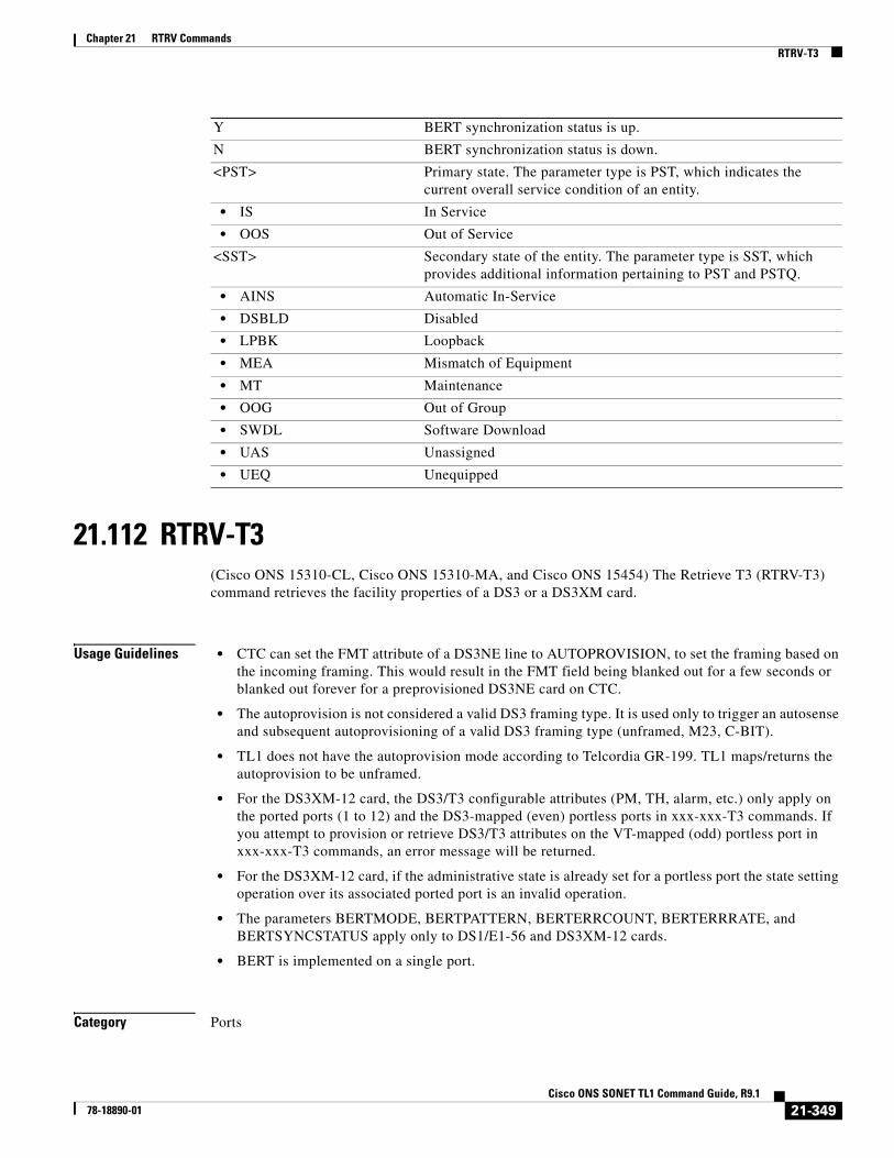
Chapter 21 RTRV CommandsRTRV-T3
21.112 RTRV-T3(Cisco ONS 15310-CL, Cisco ONS 15310-MA, and Cisco ONS 15454) The Retrieve T3 (RTRV-T3) command retrieves the facility properties of a DS3 or a DS3XM card.
Usage Guidelines • CTC can set the FMT attribute of a DS3NE line to AUTOPROVISION, to set the framing based on the incoming framing. This would result in the FMT field being blanked out for a few seconds or blanked out forever for a preprovisioned DS3NE card on CTC.
• The autoprovision is not considered a valid DS3 framing type. It is used only to trigger an autosense and subsequent autoprovisioning of a valid DS3 framing type (unframed, M23, C-BIT).
• TL1 does not have the autoprovision mode according to Telcordia GR-199. TL1 maps/returns the autoprovision to be unframed.
• For the DS3XM-12 card, the DS3/T3 configurable attributes (PM, TH, alarm, etc.) only apply on the ported ports (1 to 12) and the DS3-mapped (even) portless ports in xxx-xxx-T3 commands. If you attempt to provision or retrieve DS3/T3 attributes on the VT-mapped (odd) portless port in xxx-xxx-T3 commands, an error message will be returned.
• For the DS3XM-12 card, if the administrative state is already set for a portless port the state setting operation over its associated ported port is an invalid operation.
• The parameters BERTMODE, BERTPATTERN, BERTERRCOUNT, BERTERRRATE, and BERTSYNCSTATUS apply only to DS1/E1-56 and DS3XM-12 cards.
• BERT is implemented on a single port.
Category Ports
Y BERT synchronization status is up.
N BERT synchronization status is down.
<PST> Primary state. The parameter type is PST, which indicates the current overall service condition of an entity.
• IS In Service
• OOS Out of Service
<SST> Secondary state of the entity. The parameter type is SST, which provides additional information pertaining to PST and PSTQ.
• AINS Automatic In-Service
• DSBLD Disabled
• LPBK Loopback
• MEA Mismatch of Equipment
• MT Maintenance
• OOG Out of Group
• SWDL Software Download
• UAS Unassigned
• UEQ Unequipped
21-349Cisco ONS SONET TL1 Command Guide, R9.1
78-18890-01

Chapter 21 RTRV CommandsRTRV-T3
Security Retrieve
Input Format RTRV-T3:[<TID>]:<AID>:<CTAG>[::::];
Input Example RTRV-T3:CERENT:FAC-1-2:123;
Input Parameters
Output Format SID DATE TIMEM CTAG COMPLD“<AID>::[FMT=<FMT>],[LINECDE=<LINECDE>],[LBO=<LBO>],[INHFELPBK=<INHFELPBK>],[TACC=<TAP>],[TAPTYPE=<TAPTYPE>],[SOAK=<SOAK>],[SOAKLEFT=<SOAKLEFT>],[SFBER=<SFBER>],[SDBER=<SDBER>],[NAME=<NAME>],[AISONLPBK=<AISONLPBK>][BERTMODE=<BERTMODE>],[BERTPATTERN=<BERTPATTERN>],[BERTERRCOUNT=<BERTERRCOUNT>],[BERTERRRATE=<BERTERRRATE>],[BERTSYNCSTATUS=<BERTSYNCSTATUS>]:<PST>,[<SST>]”;
Output Example TID-000 1998-06-20 14:30:00M 001 COMPLD"FAC-1-2::FMT=C-BIT,LINECDE=B3ZS,LBO=0-225,INHFELPBK=N,TACC=8,TAPTYPE=SINGLE,SOAK=52,SOAKLEFT=12-25,SFBER=1E-4,SDBER=1E-7,NAME=\"T3 PORT\",AISONLPBK=ALL, BERTMODE=NONE,BERTPATTERN=NONE,BERTERRCOUNT=0,BERTERRRATE=NONE,BERTSYNCSTATUS=N:OOS-AU,AINS";
Output Parameters
<AID> Access identifier from the “26.15 FACILITY” section on page 35.
<AID> Access identifier from the “26.15 FACILITY” section on page 35.
<FMT> (Optional) Digital signal format. The parameter type is DS_LINE_TYPE, which is the DS123 line type.
• C-BIT C-BIT line type applies to the DS3XM and DS3E cards.
• M13 M13 line type applies to the DS3XM and DS3E cards.
• UNFRAMED Line type is unframed. The old DS3 (L3M) and DS3CR cards can only run in unframed mode.
<LINECDE> (Optional) Line code. The parameter type is DS_LINE_CODE, which is the DS123 line code.
• B3ZS Binary three-zero substitution.
<LBO> (Optional) Line buildout settings. LBO is an integer. The parameter type is E_LBO, which is the electrical signal line buildout.
• 0–225 Electrical signal line buildout range is 0–225.
• 226–450 Electrical signal line buildout range is 226–450.
21-350Cisco ONS SONET TL1 Command Guide, R9.1
78-18890-01
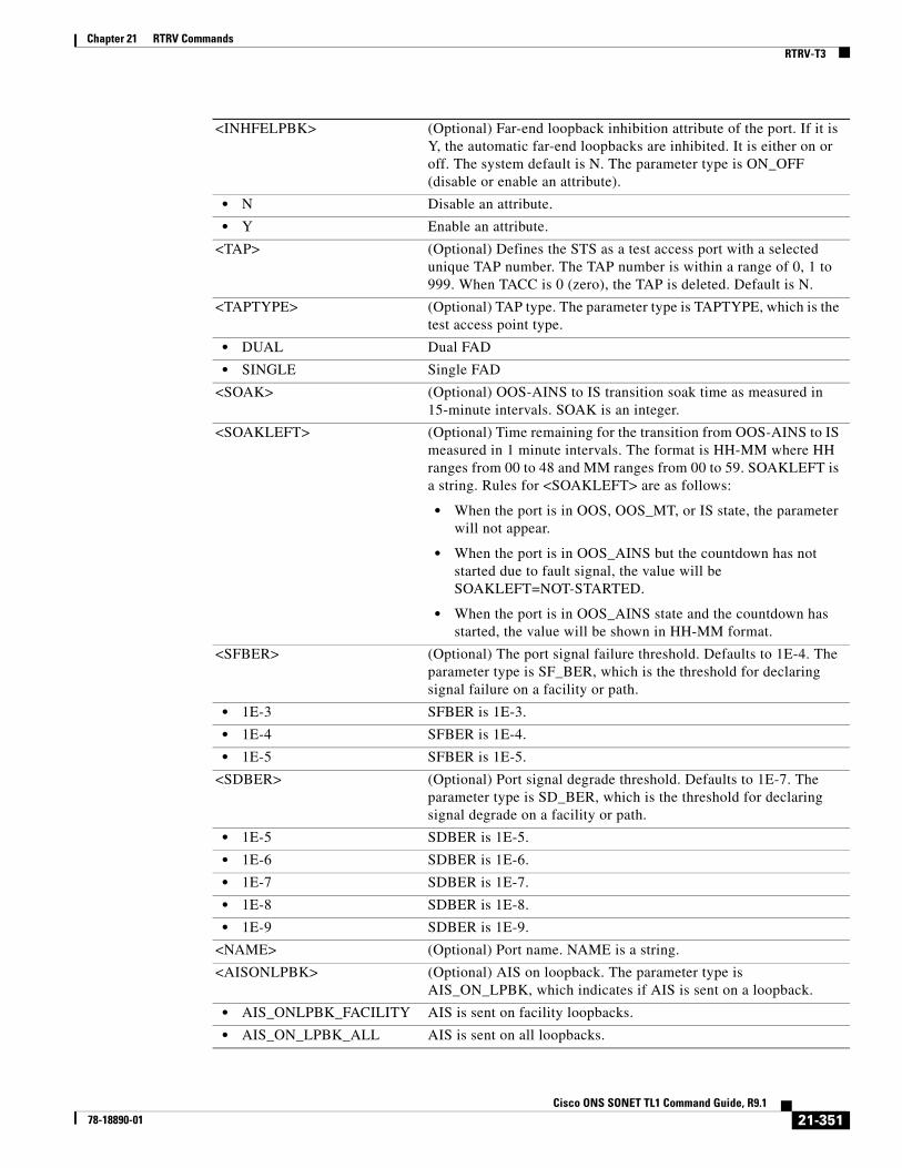
Chapter 21 RTRV CommandsRTRV-T3
<INHFELPBK> (Optional) Far-end loopback inhibition attribute of the port. If it is Y, the automatic far-end loopbacks are inhibited. It is either on or off. The system default is N. The parameter type is ON_OFF (disable or enable an attribute).
• N Disable an attribute.
• Y Enable an attribute.
<TAP> (Optional) Defines the STS as a test access port with a selected unique TAP number. The TAP number is within a range of 0, 1 to 999. When TACC is 0 (zero), the TAP is deleted. Default is N.
<TAPTYPE> (Optional) TAP type. The parameter type is TAPTYPE, which is the test access point type.
• DUAL Dual FAD
• SINGLE Single FAD
<SOAK> (Optional) OOS-AINS to IS transition soak time as measured in 15-minute intervals. SOAK is an integer.
<SOAKLEFT> (Optional) Time remaining for the transition from OOS-AINS to IS measured in 1 minute intervals. The format is HH-MM where HH ranges from 00 to 48 and MM ranges from 00 to 59. SOAKLEFT is a string. Rules for <SOAKLEFT> are as follows:
• When the port is in OOS, OOS_MT, or IS state, the parameter will not appear.
• When the port is in OOS_AINS but the countdown has not started due to fault signal, the value will be SOAKLEFT=NOT-STARTED.
• When the port is in OOS_AINS state and the countdown has started, the value will be shown in HH-MM format.
<SFBER> (Optional) The port signal failure threshold. Defaults to 1E-4. The parameter type is SF_BER, which is the threshold for declaring signal failure on a facility or path.
• 1E-3 SFBER is 1E-3.
• 1E-4 SFBER is 1E-4.
• 1E-5 SFBER is 1E-5.
<SDBER> (Optional) Port signal degrade threshold. Defaults to 1E-7. The parameter type is SD_BER, which is the threshold for declaring signal degrade on a facility or path.
• 1E-5 SDBER is 1E-5.
• 1E-6 SDBER is 1E-6.
• 1E-7 SDBER is 1E-7.
• 1E-8 SDBER is 1E-8.
• 1E-9 SDBER is 1E-9.
<NAME> (Optional) Port name. NAME is a string.
<AISONLPBK> (Optional) AIS on loopback. The parameter type is AIS_ON_LPBK, which indicates if AIS is sent on a loopback.
• AIS_ONLPBK_FACILITY AIS is sent on facility loopbacks.
• AIS_ON_LPBK_ALL AIS is sent on all loopbacks.
21-351Cisco ONS SONET TL1 Command Guide, R9.1
78-18890-01

Chapter 21 RTRV CommandsRTRV-T3
• AIS_ON_LPBK_OFF AIS is not sent on loopbacks.
• AIS_ON_LPBK_TERMINAL AIS is sent on terminal loopbacks.
<BERTMODE> Specifies the mode [Test Pattern Generator (TPG) and Test Pattern Monitor (TPM)] of the port for BERT.
• NONE BERT mode not enabled.
• TPGM-L Test pattern generator and monitor on line-side.
• TPGM-B Test pattern generator and monitor on backplane.
• TPG-L Test pattern generator on line-side.
• TPM-L Test pattern monitor on line-side.
• TPG-B Test pattern generator on backplane.
• TPM-B Test pattern monitor on backplane.
<BERTPATTERN> Specifies the error pattern to be injected for BERT.
• NONE BERT pattern not enabled.
• PRBS15 PRBS15 test pattern.
• PRBS20 PRBS20 test pattern.
• PRBS23 PRBS23 test pattern.
• QRSS QRSS test pattern.
• ALT-ONE-ALT-ZERO Alternate one and zero pattern.
<BERTERRCOUNT> Integer value. Value –1 indicates that BERT is disabled/not supported.
<BERTERRRATE> Specifies the BERT error rate received.
• NONE No bit errors.
• SINGLE Single bit error.
• 1E-3 Bit errors in 1E-3 rate.
• 1E-4 Bit errors in 1E-4 rate.
• 1E-5 Bit errors in 1E-5 rate.
• 1E-6 Bit errors in 1E-6 rate.
<BERTSYNCSTATUS> Synchronization status of BERT values. The parameter type is Y_N, which specifies if synchronization status is up or down.
Y BERT synchronization status is up.
N BERT synchronization status is down.
<PST> Primary state. The parameter type is PST, which indicates the current overall service condition of an entity.
• IS In Service
• OOS Out of Service
<SST> Secondary state of the entity. The parameter type is SST, which provides additional information pertaining to PST and PSTQ.
• AINS Automatic In-Service
• DSBLD Disabled
• LPBK Loopback
• MEA Mismatch of Equipment
• MT Maintenance
21-352Cisco ONS SONET TL1 Command Guide, R9.1
78-18890-01

Chapter 21 RTRV CommandsRTRV-TACC
21.113 RTRV-TACC(Cisco ONS 15310-CL, Cisco ONS 15310-MA, Cisco ONS 15454, and Cisco ONS 15600) The Retrieve Test Access (RTRV-TACC) command retrieves details associated with a TAP. The TAP is identified by the TAP number. The ALL input TAP value means that the command will return all the configured TACCs in the NE.
Note The RTRV-TACC command displays the working path AID irrespective of whether TACC is connected to the working or protect path of the path protected circuit.
Usage Guidelines None
Category Troubleshooting and Test Access
Security Retrieve
Input Format RTRV-TACC:[<TID>]:<TAP>:<CTAG>;
Input Example RTRV-TACC:CISCO:241:CTAG;
Input Parameters
Output Format SID DATE TIMEM CTAG COMPLD “<TAP>:<TACC_AIDA>,<TACC_AIDB>,[<MD>],[<CROSSCONNECTID1>], <AIDUNIONID>,<PATHWIDTH>”;
• OOG Out of Group
• SWDL Software Download
• UAS Unassigned
• UEQ Unequipped
<TAP> The assigned number for AID being used as a test access point. TAP must be an integer within a range of 1 to 999. The ALL TAP value returns all the configured TACCs in this NE. TAP is a string.
21-353Cisco ONS SONET TL1 Command Guide, R9.1
78-18890-01

Chapter 21 RTRV CommandsRTRV-TACC
Output Example TID-000 1998-06-20 14:30:00M 001 COMPLD “241:STS-2-1-1,STS-2-1-2,MONE,STS-12-1-1,STS-13-1-1,STS1”;
Output Parameters <TAP> The assigned number for the AID being used as a test access point. TAP is an integer.
<TACC_AIDA> Access identifier from the “26.10 CrossConnectId” section on page 22. The A path of the test access point. The first STS/VT path of the TAP.
<TACC_AIDB> Access identifier from the “26.10 CrossConnectId” section on page 22. The B path of the test access point. The second STS/VT path of the TAP. For single FAD TAP this path will be empty.
<MD> (Optional) Test access mode. It identifies the mode of access between the TAP and the circuit connected to the TAP. The parameter type is TACC_MODE, which is the test access mode.
• LOOPE Indicates to split both the A and B paths. Connect the line incoming from E direction to the line outgoing in the E direction, and connect this looped configuration to the FAD. The line outgoing in the F direction will have a QRS connected, and the line incoming from the F direction shall be terminated by the nominal characteristic impedance of the line. Intrusive test access mode.
• LOOPF Indicates to split both the A and B paths. Connect the line incoming from F direction to the line outgoing in the F direction, and connect this looped configuration to the FAD. The line outgoing in the E direction shall have a QRS connected, and the line incoming from the E direction shall be terminated by the nominal characteristic impedance of the line. Intrusive test access mode.
• MONE Indicates that a monitor connection is to be provided from the FAD to the A transmission path of the accessed circuit.
• MONEF Indicates that a monitor connection is to be provided from the FAD1 to a DFAD, or from the odd pair of a FAP to the A transmission path and from FAD2 of the same DFAD, or from the even pair of a FAP to the B transmission path of the accessed circuit.
• MONF Indicates that a monitor connection is to be provided from the FAD to the B transmission path of the accessed circuit.
• SPLTA Indicates that a connection is to be provided from both the E and F sides of the A transmission path of the circuit under test to the FAD and split the A transmission path. Intrusive test access mode.
• SPLTB Indicates that a connection is to be provided from both the E and F sides of the B transmission path of the circuit under test to the FAD and split the B transmission path. Intrusive test access mode.
• SPLTE Indicates to split both the A and B paths and connect the E side of the accessed circuit to the FAD. The line outgoing in the F direction shall have a QRS connected, and the line incoming from the F direction shall have a QRS connected, and the line incoming from the E direction shall be terminated by the nominal characteristic impedance of the line. Intrusive test access mode.
21-354Cisco ONS SONET TL1 Command Guide, R9.1
78-18890-01
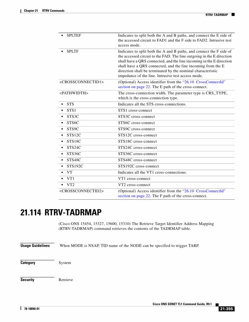
Chapter 21 RTRV CommandsRTRV-TADRMAP
21.114 RTRV-TADRMAP(Cisco ONS 15454, 15327, 15600, 15310) The Retrieve Target Identifier Address Mapping (RTRV-TADRMAP) command retrieves the contents of the TADRMAP table.
Usage Guidelines When MODE is NSAP, TID name of the NODE can be specified to trigger TARP.
Category System
Security Retrieve
• SPLTEF Indicates to split both the A and B paths, and connect the E side of the accessed circuit to FAD1 and the F side to FAD2. Intrusive test access mode.
• SPLTF Indicates to split both the A and B paths, and connect the F side of the accessed circuit to the FAD. The line outgoing in the E direction shall have a QRS connected, and the line incoming in the E direction shall have a QRS connected, and the line incoming from the E direction shall be terminated by the nominal characteristic impedance of the line. Intrusive test access mode.
<CROSSCONNECTID1> (Optional) Access identifier from the “26.10 CrossConnectId” section on page 22. The E path of the cross-connect.
<PATHWIDTH> The cross-connection width. The parameter type is CRS_TYPE, which is the cross-connection type.
• STS Indicates all the STS cross-connections.
• STS1 STS1 cross-connect
• STS3C STS3C cross-connect
• STS6C STS6C cross-connect
• STS9C STS9C cross-connect
• STS12C STS12C cross-connect
• STS18C STS18C cross-connect
• STS24C STS24C cross-connect
• STS36C STS36C cross-connect
• STS48C STS48C cross-connect
• STS192C STS192C cross-connect
• VT Indicates all the VT1 cross-connections.
• VT1 VT1 cross-connect
• VT2 VT2 cross-connect
<CROSSCONNECTID2> (Optional) Access identifier from the “26.10 CrossConnectId” section on page 22. The F path of the cross-connect.
21-355Cisco ONS SONET TL1 Command Guide, R9.1
78-18890-01
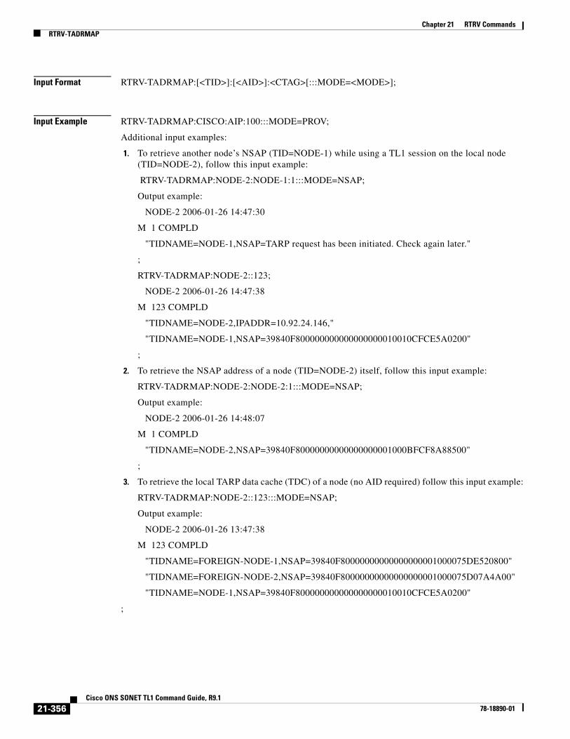
Chapter 21 RTRV CommandsRTRV-TADRMAP
Input Format RTRV-TADRMAP:[<TID>]:[<AID>]:<CTAG>[:::MODE=<MODE>];
Input Example RTRV-TADRMAP:CISCO:AIP:100:::MODE=PROV;
Additional input examples:
1. To retrieve another node’s NSAP (TID=NODE-1) while using a TL1 session on the local node (TID=NODE-2), follow this input example:
RTRV-TADRMAP:NODE-2:NODE-1:1:::MODE=NSAP;
Output example:
NODE-2 2006-01-26 14:47:30
M 1 COMPLD
"TIDNAME=NODE-1,NSAP=TARP request has been initiated. Check again later."
;
RTRV-TADRMAP:NODE-2::123;
NODE-2 2006-01-26 14:47:38
M 123 COMPLD
"TIDNAME=NODE-2,IPADDR=10.92.24.146,"
"TIDNAME=NODE-1,NSAP=39840F800000000000000000010010CFCE5A0200"
;
2. To retrieve the NSAP address of a node (TID=NODE-2) itself, follow this input example:
RTRV-TADRMAP:NODE-2:NODE-2:1:::MODE=NSAP;
Output example:
NODE-2 2006-01-26 14:48:07
M 1 COMPLD
"TIDNAME=NODE-2,NSAP=39840F80000000000000000001000BFCF8A88500"
;
3. To retrieve the local TARP data cache (TDC) of a node (no AID required) follow this input example:
RTRV-TADRMAP:NODE-2::123:::MODE=NSAP;
Output example:
NODE-2 2006-01-26 13:47:38
M 123 COMPLD
"TIDNAME=FOREIGN-NODE-1,NSAP=39840F80000000000000000001000075DE520800"
"TIDNAME=FOREIGN-NODE-2,NSAP=39840F80000000000000000001000075D07A4A00"
"TIDNAME=NODE-1,NSAP=39840F800000000000000000010010CFCE5A0200"
;
21-356Cisco ONS SONET TL1 Command Guide, R9.1
78-18890-01

Chapter 21 RTRV CommandsRTRV-TH-<MOD2>
Input Parameters
Output Format SID DATE TIMEM CTAG COMPLD “[TID=<TID>],[IP ADDRESS =<IPADDRESS>],[NSAP=<NSAP>]”;
Output Example TID-000 1998-06-20 14:30:00M 001 COMPLD “TID=RANGERS1,IP ADDRESS = 64.101.245.5, NSAP=39840FFFFFFFOOOODDDDAA01D00F0400000700”;
Output Parameters
21.115 RTRV-TH-<MOD2>(Cisco ONS 15454, 15327, 15600, 15310) The Retrieve Threshold for 10GFC, 10GIGE, 40GIGE, 1GFC, 1GFICON, 2GFC, 2GFICON, 5GIB, 8GFC, CLNT, D1VIDEO, DS1, DV6000, DVBASI, E1, E3, E4, EC1, ESCON, ETRCLO, ETH, FSTE, G1000, GFPOS, GIGE, HDTV, ISC1, ILK, ISCCOMPAT, ISC3PEER2R, ISC3PEER1G, ISC3PEER2G, OC12, OC192, OC3, OC48, OC768, OCH, OMS, OTS, OTU3, POS, STS1, STS12C, STS18C, STS192C, STS24C, STS36C, STS3C, STS48C, STS96C, STS6C, STS9C, T1, T3, VT1, or VT2 (RTRV-TH-<MOD2>) command retrieves the threshold level of one or more monitored parameters.
Usage Guidelines See Table 28-1 on page 1 for supported modifiers by platform.
Note • After the BLSR switch, the working path is switched out, the traffic goes through the protection path, and the threshold can be retrieved from the protection path.
• If there is an STS PCA on the protection path during BLSR switching, the PCA path is preemptive; sending this command on the protection path after the BLSR switch, the command returns the PMs off the protection path, not from the PCA path.
<AID> AID is a target identifier from the “26.1 ALL” section on page 1. AID is a string. If AID is not null, MODE must be NSAP.
<MODE> Must not be null. The parameter type is MODE, which determines the category of addresses to return.
• ALL Discovered and provisioned addresses
• DISC Discovered addresses
• IP IP addresses
• NSAP NSAP addresses
• PROV Provisioned
<TID> (Optional) Target identifier. TID is a string.
<IPADDRESS> (Optional) IP address. IPADDRESS is a string.
<NSAP> (Optional) NSAP address. NSAP is a string.
21-357Cisco ONS SONET TL1 Command Guide, R9.1
78-18890-01

Chapter 21 RTRV CommandsRTRV-TH-<MOD2>
• The message is issued to retrieve the thresholds for PM and alarm thresholds. If it is used to retrieve the alarm thresholds, the time-period is not applicable.
• The presentation rules are as follows:
– Client port only–Laser, Alarm and SONET Thresholds are applicable and will appear. Laser and alarm thresholds are only for near end. If the card payload is in SONET mode, then SONET thresholds will appear. The Receiver Temperature Montypes (RXT) are only applicable to the Trunk Port. The Transceiver Voltage Montypes (XCVR) are not applicable, though it might be displayed or handled.
– Laser and Alarm thresholds are always available. Laser and alarm thresholds are only for near end. If ITU-T G.709 is enabled, then the OTN thresholds will appear. If ITU-T G.709 is enabled and FEC is enabled, then the FEC thresholds will appear. If the card payload is in SONET mode, then SONET thresholds will appear. The Transceiver Voltage Montypes (XCVR) are not applicable, though it is displayed or handled.
• Refer to the Cisco ONS SDH and Cisco ONS 15600 SDH TL1 Reference Guide for specific card provisioning rules.
Category Performance
Security Retrieve
Input Format RTRV-TH-<MOD2>:[<TID>]:<AID>:<CTAG>::[<MONTYPE>],[<LOCN>],[<TMPER>][::];
Input Example RTRV-TH-T3:CISCO:FAC-1-3:1234::CVL,NEND,15-MIN;
Input Parameters <AID> Access identifier from the “26.1 ALL” section on page 1.
<MONTYPE> Monitored type.
Note MONTYPE defaults to CVL for OCN/EC1/DSN, to ESP for STSp, to UASV for VT1, and to AISSP for the DS1 layer of the DS3XM card.
A null value is equivalent to ALL. The parameter type is ALL_MONTYPE, which is the monitoring type list.
• AISSP Alarm Indication Signal Seconds—Path
• ALL All possible values
• BBE-PM OTN—Background Block Errors—Path Monitor Point
• BBE-SM OTN—Background Block Errors—Section Monitor Point
• BBER-PM OTN—Background Block Error Ratio—Path Monitor Point expressed as one tenth of a percentage.
• BBER-SM OTN—Background Block Error Ratio—Section Monitor Point expressed as one tenth of a percentage.
21-358Cisco ONS SONET TL1 Command Guide, R9.1
78-18890-01
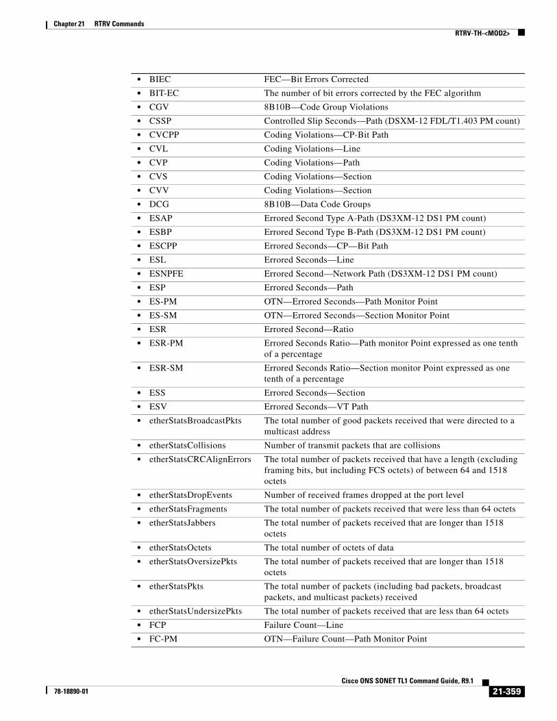
Chapter 21 RTRV CommandsRTRV-TH-<MOD2>
• BIEC FEC—Bit Errors Corrected
• BIT-EC The number of bit errors corrected by the FEC algorithm
• CGV 8B10B—Code Group Violations
• CSSP Controlled Slip Seconds—Path (DSXM-12 FDL/T1.403 PM count)
• CVCPP Coding Violations—CP-Bit Path
• CVL Coding Violations—Line
• CVP Coding Violations—Path
• CVS Coding Violations—Section
• CVV Coding Violations—Section
• DCG 8B10B—Data Code Groups
• ESAP Errored Second Type A-Path (DS3XM-12 DS1 PM count)
• ESBP Errored Second Type B-Path (DS3XM-12 DS1 PM count)
• ESCPP Errored Seconds—CP—Bit Path
• ESL Errored Seconds—Line
• ESNPFE Errored Second—Network Path (DS3XM-12 DS1 PM count)
• ESP Errored Seconds—Path
• ES-PM OTN—Errored Seconds—Path Monitor Point
• ES-SM OTN—Errored Seconds—Section Monitor Point
• ESR Errored Second—Ratio
• ESR-PM Errored Seconds Ratio—Path monitor Point expressed as one tenth of a percentage
• ESR-SM Errored Seconds Ratio—Section monitor Point expressed as one tenth of a percentage
• ESS Errored Seconds—Section
• ESV Errored Seconds—VT Path
• etherStatsBroadcastPkts The total number of good packets received that were directed to a multicast address
• etherStatsCollisions Number of transmit packets that are collisions
• etherStatsCRCAlignErrors The total number of packets received that have a length (excluding framing bits, but including FCS octets) of between 64 and 1518 octets
• etherStatsDropEvents Number of received frames dropped at the port level
• etherStatsFragments The total number of packets received that were less than 64 octets
• etherStatsJabbers The total number of packets received that are longer than 1518 octets
• etherStatsOctets The total number of octets of data
• etherStatsOversizePkts The total number of packets received that are longer than 1518 octets
• etherStatsPkts The total number of packets (including bad packets, broadcast packets, and multicast packets) received
• etherStatsUndersizePkts The total number of packets received that are less than 64 octets
• FCP Failure Count—Line
• FC-PM OTN—Failure Count—Path Monitor Point
21-359Cisco ONS SONET TL1 Command Guide, R9.1
78-18890-01

Chapter 21 RTRV CommandsRTRV-TH-<MOD2>
• FC-SM OTN—Failure Count—Section Monitor Point
• HP-AR Availability Ratio
• HP-BBE High-Order Path Background Block Error
• HP-BBER High-Order Path Background Block Error Ratio
• HP-EB High-Order Path Errored Block
• HP-ES High-Order Path Errored Second
• HP-ESA High-Order Path Errored Seconds—A
• HP-ESB High-Order Path Errored Seconds—B
• HP-ESR High-Order Path Errored Second Ratio
• HP-FC High-Order Path Failure Count
• HP-NPJC-PDET High Order Path Negative Pointer Justification Count
• HP-NPJC-PGEN High Order Path, Negative Pointer Justification Count
• HP-OI Outage Intensity
• HP-PJCDIFF High Order Path Pointer Justification Count Difference
• HP-PJCS-PDET High Order Path Pointer Justification Count
• HP-PJCS-PGEN High Order Path Pointer Justification Count Seconds
• HP-PPJC-PDET High Order Path Positive Pointer Justification Count
• HP-PPJC-PGEN High Order Path, Positive Pointer Justification Count
• HP-SEPI The number of SEP events in available time
• HP-SES High-Order Path Severely Errored Seconds
• HP-SESR High-Order Path Severely Errored Second Ratio
• HP-UAS High-Order Path Unavailable Seconds
• ifInBroadcastPkts Number of broadcast packets received since the last counter reset
• ifInDiscards The number of inbound packets
• ifInErrorBytePktss Receive Error Byte
• ifInErrors The number of inbound packets (or transmission units) that contained errors
• ifInFramingErrorPkts Receive Framing Error
• ifInJunkInterPkts Receive Interpacket Junk
• ifInMulticastPkts Number of multicast packets received since the last counter reset
• ifInOctets Number of bytes transmitted since the last counter reset
• ifInUcastPkts Number of unicast packets received since the last counter reset
• ifOutBroadcastPkts Number of broadcast packets transmitted
• ifOutDiscards The number of outbound packets
• ifOutErrors The number of outbound packets (or transmission units) that could not be transmitted because of errors
• ifOutMulticastPkts Number of multicast packets transmitted
• ifOutPayloadCrcErrors Received payload CRC errors
• ifOutUcastPkts Number of unicast packets transmitted
• IOS 8B10B- Idle Ordered Sets
• IPC Invalid Packet Count
• LBCL-AVG Average Laser Bias Current in microA
21-360Cisco ONS SONET TL1 Command Guide, R9.1
78-18890-01

Chapter 21 RTRV CommandsRTRV-TH-<MOD2>
• LBCL-MAX Maximum Laser Bias Current in microA
• LBCL-MIN Minimum Laser Bias Current in microA
• LBCN Normalized Laser Bias Current for OC3-8
• LBCN-HWT Normalized Laser Bias Current—Higher Threshold
• LBCN-LWT Normalized Laser Bias Current—Lower Threshold
• LOSSL Loss of Signal Seconds—Line
• LP-BBE Low-Order Path Background Block Error
• LP-BBER Low-Order Path Background Block Error Ratio
• LP-EB Low-Order Path Errored Block
• LP-ES Low-Order Path Errored Second
• LP-ESA Low-Order Path Errored Seconds-A
• LP-ESB Low-Order Path Errored Seconds-B
• LP-ESR Low-Order Path Errored Second Ratio
• LP-FC Low-Order Path Failure Count
• LP-NPJC-DET Low-Order Negative Pointer Justification Count, Detected
• LP-NPJC-GEN Low Order Negative Pointer Justification Count, Generated
• LP-PPJC-DET Low-Order Positive Pointer Justification Count, Detected
• LP-PPJC-GEN Low-Order positive Pointer Justification Count, Generated
• LP-SEP Low-Order Path Severely Errored Period
• LP-SEPI Low-Order Path Severely Errored Period Intensity
• LP-SES Low-Order Path Severely Errored
• LP-UAS Low-Order Path Unavailable Seconds
• MS-PSC Protection switch count
• MS-PSD Protection switch duration
• NIOS 8B10B—Non Idle Ordered Sets
• NPJC-PDET Negative Pointer Justification Count, Path Detected
• NPJC-PGEN Negative Pointer Justification Count, Path Generated
• OPR-AVG Average Receive Power in one tenth of a microwatt
• OPR-MAX Maximum Receive Power in one tenth of a microwatt
• OPR-MIN Minimum Receive Power in one tenth of a microwatt
• OPRN Normalized Optical Receive Power for OC3-8
• OPRN-MAX Maximum value for OPRN
• OPRN-MIN Minimum value for OPRN
• OPT-AVG Average Transmit Power in one tenth of a microwatt
• OPT-MAX Maximum Transmit Power in one tenth of a microwatt
• OPT-MIN Minimum Transmit Power in one tenth of a microwatt
• OPTN Normalized value for Optical Power Transmitted for the OC3-8 card
• OPTN-MAX Maximum value for OPTN
• OPTN-MIN Minimum value for OPTN
• OPWR-AVG Optical Power—Average Interval Value in one tenth of a dBm
• OPWR-MAX Optical Power—Maximum Interval Value in one tenth of a dBm
21-361Cisco ONS SONET TL1 Command Guide, R9.1
78-18890-01

Chapter 21 RTRV CommandsRTRV-TH-<MOD2>
• OPWR-MIN Optical Power—Minimum Interval Value in one tenth of a dBm
• PPJC-PDET Positive Pointer Justification Count, Path Detected
• PPJC-PGEN Positive Pointer Justification Count, Path Generated
• PSC Protection Switching Count
• PSC-R Protection Switching Count—Ring
• PSC-S Protection Switching Count—Span
• PSC-W Protection Switching Count—Working
• PSD Protection Switching Duration
• PSD-R Protection Switching Duration—Ring
• PSD-S Protection Switching Duration—Span
• PSD-W Protection Switching Duration—Working
• SASCPP Severely Errored Framing/AIS Second—CP-Bit Path
• SASP Severely Errored Framing/AIS Seconds Path
• SEFS Severely Errored Framing Seconds
• SEFSP Severely Errored Framing Seconds—Path (DS3XM-12 DS1 PM count)
• SESCPP Severely Errored Second—CP-Bit Path
• SESL Severely Errored Second—Line
• SESNPFE Severely Errored Second—Network Path (DS3XM-12 DS1 PM count)
• SESP Severely Errored Second—Path
• SES-PM OTN—Severely Errored Second—Path
• SESR-PM OTN—Severely Errored Second Ratio—Path Monitor Point expressed as one tenth of a percentage
• SESR-SM OTN—Severely Errored Second Ratio—Section Monitor Point expressed as one tenth of a percentage
• SESS Severely Errored Second—Section
• SES-SM OTN—Severely Errored Second—Section Monitor Point
• SESV Severely Errored Second—VT Path
• UASCPP Unavailable Second—CP-Bit Path
• UASL Unavailable Second—Line
• UASNPFE Unavailable Second—Network Path (DS3XM-12 DS1 PM count)
• UASP Unavailable Second—Path
• UAS-PM OTN—Unavailable Second—Path Monitor Point
• UAS-SM OTN—Unavailable Second—Section Monitor Point
• UASV Unavailable Second—VT Path
• UNC-WORDS FEC—Uncorrectable Words
• VPC Valid Packet Count
21-362Cisco ONS SONET TL1 Command Guide, R9.1
78-18890-01

Chapter 21 RTRV CommandsRTRV-TH-<MOD2>
Output Format SID DATE TIMEM CTAG COMPLD “<AID>,[<AIDTYPE>]:<MONTYPE>,[<LOCN>],,<THLEV>,[<TMPER>]”;
Output Example TID-000 1998-06-20 14:30:00M 001 COMPLD “FAC-1-3,DS3:CVL,NEND,,1,15-MIN”;
Output Parameters
<LOCN> Location associated with a particular command in reference to the entity identified by the AID. LOCN defaults to NEND (near end). A null value is equivalent to ALL. The parameter type is LOCATION, which is the location where the action is to take place.
• FEND Action occurs on the far end of the facility.
• NEND Action occurs on the near end of the facility.
<TMPER> Accumulation time period for performance counters. Defaults to 15-MIN. Must not be null. The parameter type is TMPER, which is the accumulation time period for the performance management center
• 1-DAY Performance parameter accumulation interval length; every 24-hours. For SONET PM data only one day of history data is available. For RMON managed PM data seven days of history data are available.
• 1-HR Performance parameter accumulation interval length; every 1 hour. This is only applicable to RMON managed PM data. There are 24 hours of history data available.
• 1-MIN Performance parameter accumulation interval length; every 1 minute. This is only applicable to RMON managed PM data. There are 60 minutes of history available.
• 15-MIN Performance parameter accumulation interval length; every 15 minutes. There are 32 15-MIN buckets of history data available for this accumulation interval length.
• RAW-DATA Performance parameter accumulation interval length; starting from the last time the counters were cleared. This is only applicable to RMON managed PMs.
<AID> Access identifier from the “26.1 ALL” section on page 1.
<AIDTYPE> (Optional) Type of facility, link, or other addressable entity targeted by the message. The parameter type is MOD2B, which is the alarm type.
• 1GFC 1-Gigabit Fibre Channel payload
• 1GFICON 1-Gigabit fiber connectivity payload
• 2GFC 2-Gigabit Fibre Channel payload
• 2GFICON 2-Gigabit fiber connectivity payload
21-363Cisco ONS SONET TL1 Command Guide, R9.1
78-18890-01
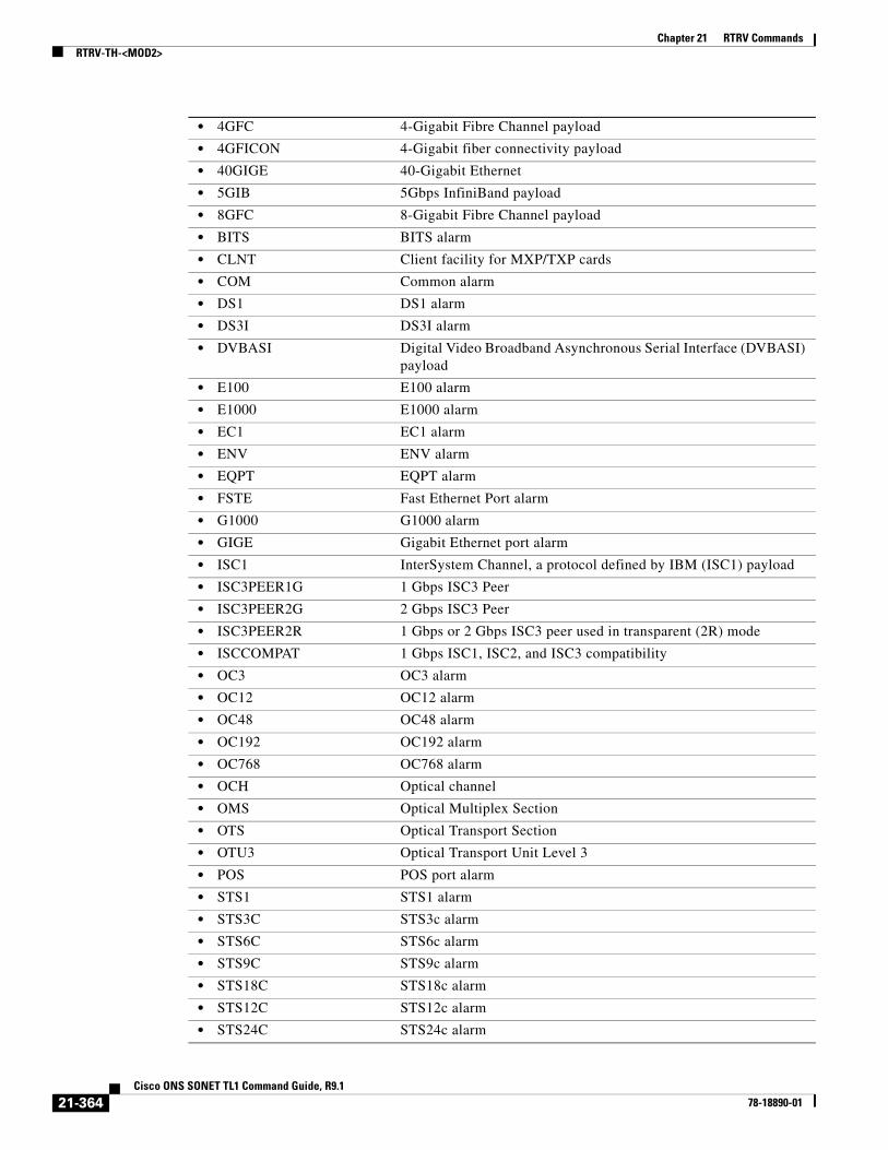
Chapter 21 RTRV CommandsRTRV-TH-<MOD2>
• 4GFC 4-Gigabit Fibre Channel payload
• 4GFICON 4-Gigabit fiber connectivity payload
• 40GIGE 40-Gigabit Ethernet
• 5GIB 5Gbps InfiniBand payload
• 8GFC 8-Gigabit Fibre Channel payload
• BITS BITS alarm
• CLNT Client facility for MXP/TXP cards
• COM Common alarm
• DS1 DS1 alarm
• DS3I DS3I alarm
• DVBASI Digital Video Broadband Asynchronous Serial Interface (DVBASI) payload
• E100 E100 alarm
• E1000 E1000 alarm
• EC1 EC1 alarm
• ENV ENV alarm
• EQPT EQPT alarm
• FSTE Fast Ethernet Port alarm
• G1000 G1000 alarm
• GIGE Gigabit Ethernet port alarm
• ISC1 InterSystem Channel, a protocol defined by IBM (ISC1) payload
• ISC3PEER1G 1 Gbps ISC3 Peer
• ISC3PEER2G 2 Gbps ISC3 Peer
• ISC3PEER2R 1 Gbps or 2 Gbps ISC3 peer used in transparent (2R) mode
• ISCCOMPAT 1 Gbps ISC1, ISC2, and ISC3 compatibility
• OC3 OC3 alarm
• OC12 OC12 alarm
• OC48 OC48 alarm
• OC192 OC192 alarm
• OC768 OC768 alarm
• OCH Optical channel
• OMS Optical Multiplex Section
• OTS Optical Transport Section
• OTU3 Optical Transport Unit Level 3
• POS POS port alarm
• STS1 STS1 alarm
• STS3C STS3c alarm
• STS6C STS6c alarm
• STS9C STS9c alarm
• STS18C STS18c alarm
• STS12C STS12c alarm
• STS24C STS24c alarm
21-364Cisco ONS SONET TL1 Command Guide, R9.1
78-18890-01

Chapter 21 RTRV CommandsRTRV-TH-<MOD2>
• STS36C STS36c alarm
• STS48C STS48c alarm
• STS192C STS192c alarm
• SYNCN SYNCN alarm
• T1 T1 alarm
• T3 T3 alarm
• TCC TCC alarm
• VT1 VT1 alarm
• VT2 VT2 alarm
<MONTYPE> Monitored type. The parameter type is ALL_MONTYPE, which is the monitoring type list.
• AISSP Alarm Indication Signal Seconds—Path
• ALL All possible values
• BBE-PM OTN—Background Block Errors—Path Monitor Point
• BBE-SM OTN—Background Block Errors—Section Monitor Point
• BBER-PM OTN—Background Block Error Ratio—Path Monitor Point expressed as one tenth of a percentage.
• BBER-SM OTN—Background Block Error Ratio—Section Monitor Point expressed as one tenth of a percentage.
• BIEC FEC—Bit Errors Corrected
• BIT-EC The number of bit errors corrected by the FEC algorithm
• CGV 8B10B—Code Group Violations
• CSSP Controlled Slip Seconds—Path (DSXM-12 FDL/T1.403 PM count)
• CVCPP Coding Violations—CP-Bit Path
• CVL Coding Violations—Line
• CVP Coding Violations—Path
• CVS Coding Violations—Section
• CVV Coding Violations—Section
• DCG 8B10B—Data Code Groups
• ESAP Errored Second Type A-Path (DS3XM-12 DS1 PM count)
• ESBP Errored Second Type B-Path (DS3XM-12 DS1 PM count)
• ESCPP Errored Seconds—CP—Bit Path
• ESL Errored Seconds—Line
• ESNPFE Errored Second—Network Path (DS3XM-12 DS1 PM count)
• ESP Errored Seconds—Path
• ES-PM OTN—Errored Seconds—Path Monitor Point
• ES-SM OTN—Errored Seconds—Section Monitor Point
• ESR Errored Second—Ratio
• ESR-PM Errored Seconds Ratio—Path monitor Point expressed as one tenth of a percentage
• ESR-SM Errored Seconds Ratio—Section monitor Point expressed as one tenth of a percentage
21-365Cisco ONS SONET TL1 Command Guide, R9.1
78-18890-01

Chapter 21 RTRV CommandsRTRV-TH-<MOD2>
• ESS Errored Seconds—Section
• ESV Errored Seconds—VT Path
• etherStatsBroadcastPkts The total number of good packets received that were directed to a multicast address
• etherStatsCollisions Number of transmit packets that are collisions
• etherStatsCRCAlignErrors The total number of packets received that have a length (excluding framing bits, but including FCS octets) of between 64 and 1518 octets
• etherStatsDropEvents Number of received frames dropped at the port level
• etherStatsFragments The total number of packets received that were less than 64 octets
• etherStatsJabbers The total number of packets received that are longer than 1518 octets
• etherStatsOctets The total number of octets of data
• etherStatsOversizePkts The total number of packets received that are longer than 1518 octets
• etherStatsPkts The total number of packets (including bad packets, broadcast packets, and multicast packets) received
• etherStatsUndersizePkts The total number of packets received that are less than 64 octets
• FCP Failure Count—Line
• FC-PM OTN—Failure Count—Path Monitor Point
• FC-SM OTN—Failure Count—Section Monitor Point
• HP-AR Availability Ratio
• HP-BBE High-Order Path Background Block Error
• HP-BBER High-Order Path Background Block Error Ratio
• HP-EB High-Order Path Errored Block
• HP-ES High-Order Path Errored Second
• HP-ESA High-Order Path Errored Seconds—A
• HP-ESB High-Order Path Errored Seconds—B
• HP-ESR High-Order Path Errored Second Ratio
• HP-FC High-Order Path Failure Count
• HP-NPJC-PDET High-Order Path Negative Pointer Justification Count
• HP-NPJC-PGEN High-Order Path Negative Pointer Justification Count
• HP-OI Outage Intensity
• HP-PJCDIFF High-Order Path Pointer Justification Count Difference
• HP-PJCS-PDET High-Order Path Pointer Justification Count Seconds, Path Detected
• HP-PJCS-PGEN High-Order Path Pointer Justification Count Seconds, Path Generated
• HP-PPJC-PDET High-Order Path Positive Pointer Justification Count, Path Detected
• HP-PPJC-PGEN High-Order Path, Positive Pointer Justification Count, Path Generated
• HP-SEPI The number of SEP events in available time
• HP-SES High-Order Path Severely Errored Seconds
21-366Cisco ONS SONET TL1 Command Guide, R9.1
78-18890-01

Chapter 21 RTRV CommandsRTRV-TH-<MOD2>
• HP-SESR High-Order Path Severely Errored Second Ratio
• HP-UAS High-Order Path Unavailable Seconds
• ifInBroadcastPkts Number of broadcast packets received since the last counter reset
• ifInDiscards The number of inbound packets
• ifInErrorBytePktss Receive Error Byte
• ifInErrors The number of inbound packets (or transmission units) that contained errors
• ifInFramingErrorPkts Receive Framing Error
• ifInJunkInterPkts Receive Interpacket Junk
• ifInMulticastPkts Number of multicast packets received since the last counter reset
• ifInOctets Number of bytes transmitted since the last counter reset
• ifInUcastPkts Number of unicast packets received since the last counter reset
• ifOutBroadcastPkts Number of broadcast packets transmitted
• ifOutDiscards The number of outbound packets
• ifOutErrors The number of outbound packets (or transmission units) that could not be transmitted because of errors
• ifOutMulticastPkts Number of multicast packets transmitted
• ifOutPayloadCrcErrors Received payload CRC errors
• ifOutUcastPkts Number of unicast packets transmitted
• IOS 8B10B- Idle Ordered Sets
• IPC Invalid Packet Count
• LBCL-AVG Average Laser Bias Current in microA
• LBCL-MAX Maximum Laser Bias Current in microA
• LBCL-MIN Minimum Laser Bias Current in microA
• LBCN Normalized Laser Bias Current for OC3-8
• LBCN-HWT Normalized Laser Bias Current—Higher Threshold
• LBCN-LWT Normalized Laser Bias Current—Lower Threshold
• LOSSL Loss of Signal Seconds—Line
• LP-BBE Low-Order Path Background Block Error
• LP-BBER Low-Order Path Background Block Error Ratio
• LP-EB Low-Order Path Errored Block
• LP-ES Low-Order Path Errored Second
• LP-ESA Low-Order Path Errored Seconds-A
• LP-ESB Low-Order Path Errored Seconds-B
• LP-ESR Low-Order Path Errored Second Ratio
• LP-FC Low-Order Path Failure Count
• LP-NPJC-DET Low-Order Negative Pointer Justification Count, Detected
• LP-NPJC-GEN Low Order Negative Pointer Justification Count, Generated
• LP-PPJC-DET Low-Order Positive Pointer Justification Count, Detected
• LP-PPJC-GEN Low-Order positive Pointer Justification Count, Generated
• LP-SEP Low-Order Path Severely Errored Period
• LP-SEPI Low-Order Path Severely Errored Period Intensity
21-367Cisco ONS SONET TL1 Command Guide, R9.1
78-18890-01

Chapter 21 RTRV CommandsRTRV-TH-<MOD2>
• LP-SES Low-Order Path Severely Errored
• LP-UAS Low-Order Path Unavailable Seconds
• MS-PSC Protection switch count
• MS-PSD Protection switch duration
• NIOS 8B10B—Non Idle Ordered Sets
• NPJC-PDET Negative Pointer Justification Count, Path Detected
• NPJC-PGEN Negative Pointer Justification Count, Path Generated
• OPR-AVG Average Receive Power in one tenth of a microwatt
• OPR-MAX Maximum Receive Power in one tenth of a microwatt
• OPR-MIN Minimum Receive Power in one tenth of a microwatt
• OPRN Normalized Optical Receive Power for OC3-8
• OPRN-MAX Maximum value for OPRN
• OPRN-MIN Minimum value for OPRN
• OPT-AVG Average Transmit Power in one tenth of a microwatt
• OPT-MAX Maximum Transmit Power in one tenth of a microwatt
• OPT-MIN Minimum Transmit Power in one tenth of a microwatt
• OPTN Normalized value for Optical Power Transmitted for the OC3-8 card
• OPTN-MAX Maximum value for OPTN
• OPTN-MIN Minimum value for OPTN
• OPWR-AVG Optical Power—Average Interval Value in one tenth of a dBm
• OPWR-MAX Optical Power—Maximum Interval Value in one tenth of a dBm
• OPWR-MIN Optical Power—Minimum Interval Value in one tenth of a dBm
• PPJC-PDET Positive Pointer Justification Count, Path Detected
• PPJC-PGEN Positive Pointer Justification Count, Path Generated
• PSC Protection Switching Count
• PSC-R Protection Switching Count—Ring
• PSC-S Protection Switching Count—Span
• PSC-W Protection Switching Count—Working
• PSD Protection Switching Duration
• PSD-R Protection Switching Duration—Ring
• PSD-S Protection Switching Duration—Span
• PSD-W Protection Switching Duration—Working
• SASCPP Severely Errored Framing/AIS Second—CP-Bit Path
• SASP Severely Errored Framing/AIS Seconds Path
• SEFS Severely Errored Framing Seconds
• SEFSP Severely Errored Framing Seconds—Path (DS3XM-12 DS1 PM count)
• SESCPP Severely Errored Second—CP-Bit Path
• SESL Severely Errored Second—Line
• SESNPFE Severely Errored Second—Network Path (DS3XM-12 DS1 PM count)
• SESP Severely Errored Second—Path
21-368Cisco ONS SONET TL1 Command Guide, R9.1
78-18890-01
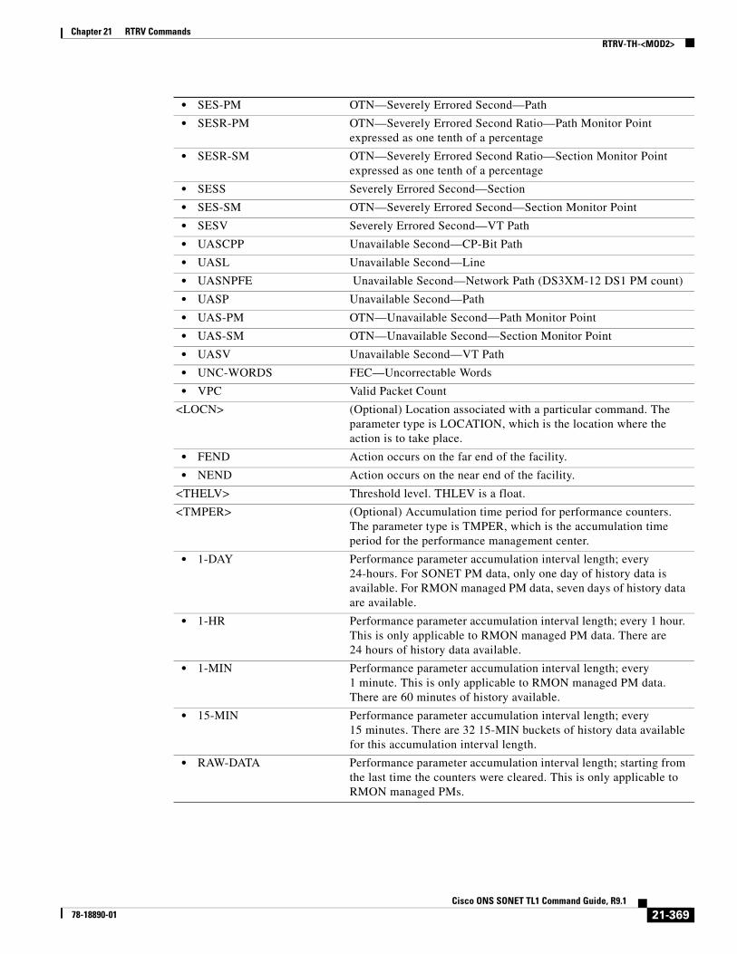
Chapter 21 RTRV CommandsRTRV-TH-<MOD2>
• SES-PM OTN—Severely Errored Second—Path
• SESR-PM OTN—Severely Errored Second Ratio—Path Monitor Point expressed as one tenth of a percentage
• SESR-SM OTN—Severely Errored Second Ratio—Section Monitor Point expressed as one tenth of a percentage
• SESS Severely Errored Second—Section
• SES-SM OTN—Severely Errored Second—Section Monitor Point
• SESV Severely Errored Second—VT Path
• UASCPP Unavailable Second—CP-Bit Path
• UASL Unavailable Second—Line
• UASNPFE Unavailable Second—Network Path (DS3XM-12 DS1 PM count)
• UASP Unavailable Second—Path
• UAS-PM OTN—Unavailable Second—Path Monitor Point
• UAS-SM OTN—Unavailable Second—Section Monitor Point
• UASV Unavailable Second—VT Path
• UNC-WORDS FEC—Uncorrectable Words
• VPC Valid Packet Count
<LOCN> (Optional) Location associated with a particular command. The parameter type is LOCATION, which is the location where the action is to take place.
• FEND Action occurs on the far end of the facility.
• NEND Action occurs on the near end of the facility.
<THELV> Threshold level. THLEV is a float.
<TMPER> (Optional) Accumulation time period for performance counters. The parameter type is TMPER, which is the accumulation time period for the performance management center.
• 1-DAY Performance parameter accumulation interval length; every 24-hours. For SONET PM data, only one day of history data is available. For RMON managed PM data, seven days of history data are available.
• 1-HR Performance parameter accumulation interval length; every 1 hour. This is only applicable to RMON managed PM data. There are 24 hours of history data available.
• 1-MIN Performance parameter accumulation interval length; every 1 minute. This is only applicable to RMON managed PM data. There are 60 minutes of history available.
• 15-MIN Performance parameter accumulation interval length; every 15 minutes. There are 32 15-MIN buckets of history data available for this accumulation interval length.
• RAW-DATA Performance parameter accumulation interval length; starting from the last time the counters were cleared. This is only applicable to RMON managed PMs.
21-369Cisco ONS SONET TL1 Command Guide, R9.1
78-18890-01

Chapter 21 RTRV CommandsRTRV-TH-ALL
21.116 RTRV-TH-ALL(Cisco ONS 15454, 15327, 15600, 15310) The Retrieve Threshold All (RTRV-TH-ALL) command retrieves the threshold level of all monitored parameters on the NE.
Usage Guidelines • After a BLSR switch, the working path is switched out, the traffic goes through the protection path, and the threshold can be retrieved from the protection STS path.
• If there is an STS PCA on the protection path during BLSR switching, the PCA path is preemptive; sending this command on the protection path after a BLSR switch, the command returns the PMs from the protection path, not from the PCA path.
• Multiple RTRV completion codes will appear after the execution of this command according to Telcordia GR-1831-CORE for bulk retrievals. The final completion code after the multiple RTRV codes is COMPLD.
• Some monitored types are not available for some cards or cross-connect types. In that case, a 0 value will appear for the monitored type. This will happen only when a user requests the thresholds of a specific monitored parameter on the NE, and the monitored type does not apply to that card or cross-connect type. When the user does not filter by monitored type, the applicable thresholds will be retrieved.
• If the user requests the thresholds of a particular monitored type and if the monitored type is not applicable to some of the entities, DENY will not be returned.
• Refer to the Cisco ONS SDH and Cisco ONS 15600 SDH TL1 Reference Guide for specific card provisioning rules.
Category Performance
Security Retrieve
Input Format RTRV-TH-ALL:[<TID>]::<CTAG>::[<MONTYPE>],[<LOCATION>],[<TMPER>][::];
Input Example RTRV-TH-ALL:CHARGERS6::123::CVL,NEND,15-MIN;
Input Parameters <MONTYPE> Monitored type. A null value defaults to ALL. The parameter type is ALL_MONTYPE, which is the monitoring type list.
• AISSP Alarm Indication Signal Seconds—Path
• ALL All possible values
• BBE-PM OTN—Background Block Errors—Path Monitor Point
• BBE-SM OTN—Background Block Errors—Section Monitor Point
• BBER-PM OTN—Background Block Error Ratio—Path Monitor Point expressed as one tenth of a percentage
21-370Cisco ONS SONET TL1 Command Guide, R9.1
78-18890-01

Chapter 21 RTRV CommandsRTRV-TH-ALL
• BBER-SM OTN—Background Block Error Ratio—Section Monitor Point expressed as one tenth of a percentage
• BIEC FEC—Bit Errors Corrected
• BIT-EC The number of bit errors corrected by the FEC algorithm
• CGV 8B10B—Code Group Violations
• CSSP Controlled Slip Seconds—Path (DSXM-12 FDL/T1.403 PM count)
• CVCPP Coding Violations—CP-Bit Path
• CVL Coding Violations—Line
• CVP Coding Violations—Path
• CVS Coding Violations—Section
• CVV Coding Violations—Section
• DCG 8B10B—Data Code Groups
• ESAP Errored Second Type A-Path (DS3XM-12 DS1 PM count)
• ESBP Errored Second Type B-Path (DS3XM-12 DS1 PM count)
• ESCPP Errored Seconds—CP—Bit Path
• ESL Errored Seconds—Line
• ESNPFE Errored Second—Network Path (DS3XM-12 DS1 PM count)
• ESP Errored Seconds—Path
• ES-PM OTN—Errored Seconds—Path Monitor Point
• ES-SM OTN—Errored Seconds—Section Monitor Point
• ESR Errored Second—Ratio
• ESR-PM Errored Seconds Ratio—Path monitor Point expressed as one tenth of a percentage
• ESR-SM Errored Seconds Ratio—Section monitor Point expressed as one tenth of a percentage
• ESS Errored Seconds—Section
• ESV Errored Seconds—VT Path
• etherStatsBroadcastPkts The total number of good packets received that were directed to a multicast address
• etherStatsCollisions Number of transmit packets that are collisions
• etherStatsCRCAlignErrors The total number of packets received that have a length (excluding framing bits, but including FCS octets) of between 64 and 1518 octets
• etherStatsDropEvents Number of received frames dropped at the port level
• etherStatsFragments The total number of packets received that were less than 64 octets
• etherStatsJabbers The total number of packets received that are longer than 1518 octets
• etherStatsOctets The total number of octets of data
• etherStatsOversizePkts The total number of packets received that are longer than 1518 octets
• etherStatsPkts The total number of packets (including bad packets, broadcast packets, and multicast packets) received
• etherStatsUndersizePkts The total number of packets received that are less than 64 octets
• FCP Failure Count—Line
• FC-PM OTN—Failure Count—Path Monitor Point
• FC-SM OTN—Failure Count—Section Monitor Point
21-371Cisco ONS SONET TL1 Command Guide, R9.1
78-18890-01
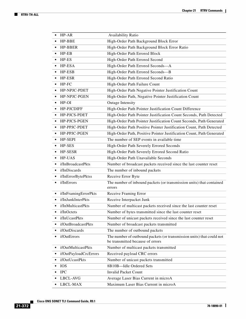
Chapter 21 RTRV CommandsRTRV-TH-ALL
• HP-AR Availability Ratio
• HP-BBE High-Order Path Background Block Error
• HP-BBER High-Order Path Background Block Error Ratio
• HP-EB High-Order Path Errored Block
• HP-ES High-Order Path Errored Second
• HP-ESA High-Order Path Errored Seconds—A
• HP-ESB High-Order Path Errored Seconds—B
• HP-ESR High-Order Path Errored Second Ratio
• HP-FC High-Order Path Failure Count
• HP-NPJC-PDET High-Order Path Negative Pointer Justification Count
• HP-NPJC-PGEN High-Order Path, Negative Pointer Justification Count
• HP-OI Outage Intensity
• HP-PJCDIFF High-Order Path Pointer Justification Count Difference
• HP-PJCS-PDET High-Order Path Pointer Justification Count Seconds, Path Detected
• HP-PJCS-PGEN High-Order Path Pointer Justification Count Seconds, Path Generated
• HP-PPJC-PDET High-Order Path Positive Pointer Justification Count, Path Detected
• HP-PPJC-PGEN High-Order Path, Positive Pointer Justification Count, Path Generated
• HP-SEPI The number of SEP events in available time
• HP-SES High-Order Path Severely Errored Seconds
• HP-SESR High-Order Path Severely Errored Second Ratio
• HP-UAS High-Order Path Unavailable Seconds
• ifInBroadcastPkts Number of broadcast packets received since the last counter reset
• ifInDiscards The number of inbound packets
• ifInErrorBytePktss Receive Error Byte
• ifInErrors The number of inbound packets (or transmission units) that contained errors
• ifInFramingErrorPkts Receive Framing Error
• ifInJunkInterPkts Receive Interpacket Junk
• ifInMulticastPkts Number of multicast packets received since the last counter reset
• ifInOctets Number of bytes transmitted since the last counter reset
• ifInUcastPkts Number of unicast packets received since the last counter reset
• ifOutBroadcastPkts Number of broadcast packets transmitted
• ifOutDiscards The number of outbound packets
• ifOutErrors The number of outbound packets (or transmission units) that could not be transmitted because of errors
• ifOutMulticastPkts Number of multicast packets transmitted
• ifOutPayloadCrcErrors Received payload CRC errors
• ifOutUcastPkts Number of unicast packets transmitted
• IOS 8B10B—Idle Ordered Sets
• IPC Invalid Packet Count
• LBCL-AVG Average Laser Bias Current in microA
• LBCL-MAX Maximum Laser Bias Current in microA
21-372Cisco ONS SONET TL1 Command Guide, R9.1
78-18890-01

Chapter 21 RTRV CommandsRTRV-TH-ALL
• LBCL-MIN Minimum Laser Bias Current in microA
• LBCN Normalized Laser Bias Current for OC3-8
• LBCN-HWT Normalized Laser Bias Current—Higher Threshold
• LBCN-LWT Normalized Laser Bias Current—Lower Threshold
• LOSSL Loss of Signal Seconds—Line
• LP-BBE Low-Order Path Background Block Error
• LP-BBER Low-Order Path Background Block Error Ratio
• LP-EB Low-Order Path Errored Block
• LP-ES Low-Order Path Errored Second
• LP-ESA Low-Order Path Errored Seconds-A
• LP-ESB Low-Order Path Errored Seconds-B
• LP-ESR Low-Order Path Errored Second Ratio
• LP-FC Low-Order Path Failure Count
• LP-NPJC-DET Low-Order Negative Pointer Justification Count, Detected
• LP-NPJC-GEN Low Order Negative Pointer Justification Count, Generated
• LP-PPJC-DET Low-Order Positive Pointer Justification Count, Detected
• LP-PPJC-GEN Low-Order positive Pointer Justification Count, Generated
• LP-SEP Low-Order Path Severely Errored Period
• LP-SEPI Low-Order Path Severely Errored Period Intensity
• LP-SES Low-Order Path Severely Errored
• LP-UAS Low-Order Path Unavailable Seconds
• MS-PSC Protection switch count
• MS-PSD Protection switch duration
• NIOS 8B10B—Non Idle Ordered Sets
• NPJC-PDET Negative Pointer Justification Count, Path Detected
• NPJC-PGEN Negative Pointer Justification Count, Path Generated
• OPR-AVG Average Receive Power in one tenth of a microwatt
• OPR-MAX Maximum Receive Power in one tenth of a microwatt
• OPR-MIN Minimum Receive Power in one tenth of a microwatt
• OPRN Normalized Optical Receive Power for OC3-8
• OPRN-MAX Maximum value for OPRN
• OPRN-MIN Minimum value for OPRN
• OPT-AVG Average Transmit Power in one tenth of a microwatt
• OPT-MAX Maximum Transmit Power in one tenth of a microwatt
• OPT-MIN Minimum Transmit Power in one tenth of a microwatt
• OPTN Normalized value for Optical Power Transmitted for the OC3-8 card
• OPTN-MAX Maximum value for OPTN
• OPTN-MIN Minimum value for OPTN
• OPWR-AVG Optical Power—Average Interval Value in one tenth of a dBm
• OPWR-MAX Optical Power—Maximum Interval Value in one tenth of a dBm
• OPWR-MIN Optical Power—Minimum Interval Value in one tenth of a dBm
21-373Cisco ONS SONET TL1 Command Guide, R9.1
78-18890-01

Chapter 21 RTRV CommandsRTRV-TH-ALL
• PPJC-PDET Positive Pointer Justification Count, Path Detected
• PPJC-PGEN Positive Pointer Justification Count, Path Generated
• PSC Protection Switching Count
• PSC-R Protection Switching Count—Ring
• PSC-S Protection Switching Count—Span
• PSC-W Protection Switching Count—Working
• PSD Protection Switching Duration
• PSD-R Protection Switching Duration—Ring
• PSD-S Protection Switching Duration—Span
• PSD-W Protection Switching Duration—Working
• SASCPP Severely Errored Framing/AIS Second—CP-Bit Path
• SASP Severely Errored Framing/AIS Seconds Path
• SEFS Severely Errored Framing Seconds
• SEFSP Severely Errored Framing Seconds—Path (DS3XM-12 DS1 PM count)
• SESCPP Severely Errored Second—CP-Bit Path
• SESL Severely Errored Second—Line
• SESNPFE Severely Errored Second—Network Path (DS3XM-12 DS1 PM count)
• SESP Severely Errored Second—Path
• SES-PM OTN—Severely Errored Second—Path
• SESR-PM OTN—Severely Errored Second Ratio—Path Monitor Point expressed as one tenth of a percentage
• SESR-SM OTN—Severely Errored Second Ratio—Section Monitor Point expressed as one tenth of a percentage
• SESS Severely Errored Second—Section
• SES-SM OTN—Severely Errored Second—Section Monitor Point
• SESV Severely Errored Second—VT Path
• UASCPP Unavailable Second—CP-Bit Path
• UASL Unavailable Second—Line
• UASNPFE Unavailable Second—Network Path (DS3XM-12 DS1 PM count)
• UASP Unavailable Second—Path
• UAS-PM OTN—Unavailable Second—Path Monitor Point
• UAS-SM OTN—Unavailable Second—Section Monitor Point
• UASV Unavailable Second—VT Path
• UNC-WORDS FEC—Uncorrectable Words
• VPC Valid Packet Count
<LOCATION> The location. A null value defaults to NEND. The parameter type is LOCATION, which is the location where the action is to take place.
• FEND Action occurs on the far end of the facility.
• NEND Action occurs on the near end of the facility.
21-374Cisco ONS SONET TL1 Command Guide, R9.1
78-18890-01

Chapter 21 RTRV CommandsRTRV-TH-ALL
Output Format SID DATE TIMEM CTAG COMPLD “<AID>,<AIDTYPE>:<MONTYPE>,<LOCATION>,,<THLEV>,<TMPER>”;
Output Example TID-000 1998-06-20 14:30:00M 001 COMPLD “FAC-1-1,DS3:CVL,NEND,,1,15-MIN”;
Output Parameters
<TMPER> The accumulation time period for performance counters. A null value defaults to 15-MIN. The parameter type is TMPER, which is the accumulation time period for the performance management counter.
• 1-DAY Performance parameter accumulation interval length is every 24 hours.
• 1-HR Performance parameter accumulation interval length is every 1 hour.
• 1-MIN Performance parameter accumulation interval length is every 1 minute.
• 15-MIN Performance parameter accumulation interval length is every 15 minutes.
• RAW-DATA Performance parameter accumulation interval length starts from the last time the counters were cleared. This is only applicable to RMON-managed PMs.
<AID> Access identifier from the “26.2 AidUnionId” section on page 12.
<AIDTYPE> Specifies the type of facility, link, or other addressable entity targeted by the message. The parameter type is MOD2B, which is the alarm type for certain generic TL1 commands.
• 1GFC 1-Gigabit Fibre Channel payload
• 1GFICON 1-Gigabit fiber connectivity payload
• 2GFC 2-Gigabit Fibre Channel payload
• 2GFICON 2-Gigabit fiber connectivity payload
• 4GFC 4-Gigabit Fibre Channel payload
• 4GFICON 4-Gigabit fiber connectivity payload
• 40GIGE 40-Gigabit Ethernet
• 5GIB 5Gbps InfiniBand payload
• 8GFC 8-Gigabit Fibre Channel payload
• BITS BITS alarm
• CLNT Client facility for MXP/TXP cards
• COM Common alarm
• DS1 DS1 alarm
• DS3I DS3I alarm
21-375Cisco ONS SONET TL1 Command Guide, R9.1
78-18890-01

Chapter 21 RTRV CommandsRTRV-TH-ALL
• DVBASI Digital Video Broadband Asynchronous Serial Interface (DVBASI) payload
• E100 E100 alarm
• E1000 E1000 alarm
• EC1 EC1 alarm
• ENV ENV alarm
• EQPT EQPT alarm
• FC Fibre Channel alarm
• FSTE FSTE alarm
• G1000 G1000 alarm
• GIGE GIGE alarm
• ISC1 InterSystem Channel, a protocol defined by IBM (ISC1) payload
• ISC3PEER1G 1 Gbps ISC3 Peer
• ISC3PEER2G 2 Gbps ISC3 Peer
• ISC3PEER2R 1 Gbps or 2 Gbps ISC3 peer used in transparent (2R) mode
• ISCCOMPAT 1 Gbps ISC1, ISC2, and ISC3 compatibility
• OC3 OC3 alarm
• OC12 OC12 alarm
• OC48 OC48 alarm
• OC192 OC192 alarm
• OC768 OC768 alarm
• OCH Optical channel
• OMS Optical Multiplex Section
• OTS Optical Transport Section
• OTU3 Optical Transport Unit Level 3
• POS POS alarm
• STS1 STS1 alarm
• STS3C STS3c alarm
• STS6C STS6c alarm
• STS9C STS9c alarm
• STS12C STS12c alarm
• STS18C STS18c alarm
• STS24C STS24c alarm
• STS48C STS48c alarm
• STS192C STS192c alarm
• SYNCN SYNCN alarm
• T1 T1 alarm
• T3 T3 alarm
• TCC TCC alarm
• VT1 VT1 alarm
• VT2 VT2 alarm
21-376Cisco ONS SONET TL1 Command Guide, R9.1
78-18890-01

Chapter 21 RTRV CommandsRTRV-TH-ALL
<MONTYPE> Monitored type. A null value defaults to ALL. The parameter type is ALL_MONTYPE, which is the monitoring type list.
• AISSP Alarm Indication Signal Seconds—Path
• ALL All possible values
• BBE-PM OTN—Background Block Errors—Path Monitor Point
• BBE-SM OTN—Background Block Errors—Section Monitor Point
• BBER-PM OTN—Background Block Error Ratio—Path Monitor Point expressed as one tenth of a percentage
• BBER-SM OTN—Background Block Error Ratio—Section Monitor Point expressed as one tenth of a percentage
• BIEC FEC—Bit Errors Corrected
• BIT-EC The number of bit errors corrected by the FEC algorithm
• CGV 8B10B—Code Group Violations
• CSSP Controlled Slip Seconds—Path (DSXM-12 FDL/T1.403 PM count)
• CVCPP Coding Violations—CP-Bit Path
• CVL Coding Violations—Line
• CVP Coding Violations—Path
• CVS Coding Violations—Section
• CVV Coding Violations—Section
• DCG 8B10B—Data Code Groups
• ESAP Errored Second Type A-Path (DS3XM-12 DS1 PM count)
• ESBP Errored Second Type B-Path (DS3XM-12 DS1 PM count)
• ESCPP Errored Seconds—CP—Bit Path
• ESL Errored Seconds—Line
• ESNPFE Errored Second—Network Path (DS3XM-12 DS1 PM count)
• ESP Errored Seconds—Path
• ES-PM OTN—Errored Seconds—Path Monitor Point
• ES-SM OTN—Errored Seconds—Section Monitor Point
• ESR Errored Second—Ratio
• ESR-PM Errored Seconds Ratio—Path monitor Point expressed as one tenth of a percentage
• ESR-SM Errored Seconds Ratio—Section monitor Point expressed as one tenth of a percentage
• ESS Errored Seconds—Section
• ESV Errored Seconds—VT Path
• etherStatsBroadcastPkts The total number of good packets received that were directed to a multicast address
• etherStatsCollisions Number of transmit packets that are collisions
• etherStatsCRCAlignErrors The total number of packets received that have a length (excluding framing bits, but including FCS octets) of between 64 and 1518 octets
• etherStatsDropEvents Number of received frames dropped at the port level
• etherStatsFragments The total number of packets received that were less than 64 octets
21-377Cisco ONS SONET TL1 Command Guide, R9.1
78-18890-01

Chapter 21 RTRV CommandsRTRV-TH-ALL
• etherStatsJabbers The total number of packets received that are longer than 1518 octets
• etherStatsOctets The total number of octets of data
• etherStatsOversizePkts The total number of packets received that are longer than 1518 octets
• etherStatsPkts The total number of packets (including bad packets, broadcast packets, and multicast packets) received
• etherStatsUndersizePkts The total number of packets received that are less than 64 octets
• FCP Failure Count—Line
• FC-PM OTN—Failure Count—Path Monitor Point
• FC-SM OTN—Failure Count—Section Monitor Point
• HP-AR Availability Ratio
• HP-BBE High-Order Path Background Block Error
• HP-BBER High-Order Path Background Block Error Ratio
• HP-EB High-Order Path Errored Block
• HP-ES High-Order Path Errored Second
• HP-ESA High-Order Path Errored Seconds—A
• HP-ESB High-Order Path Errored Seconds—B
• HP-ESR High-Order Path Errored Second Ratio
• HP-FC High-Order Path Failure Count
• HP-NPJC-PDET High-Order Path Negative Pointer Justification Count, Path Detected
• HP-NPJC-PGEN High-Order Path Negative Pointer Justification Count, Path Generated
• HP-OI Outage Intensity
• HP-PJCDIFF High-Order Path Pointer Justification Count Difference
• HP-PJCS-PDET High-Order Path Pointer Justification Count Seconds, Path Detected
• HP-PJCS-PGEN High-Order Path Pointer Justification Count Seconds, Path Generated
• HP-PPJC-PDET High-Order Path Positive Pointer Justification Count, Path Detected
• HP-PPJC-PGEN High-Order Path Positive Pointer Justification Count, Path Generated
• HP-SEPI The number of SEP events in available time
• HP-SES High-Order Path Severely Errored Seconds
• HP-SESR High-Order Path Severely Errored Second Ratio
• HP-UAS High-Order Path Unavailable Seconds
• ifInBroadcastPkts Number of broadcast packets received since the last counter reset
• ifInDiscards The number of inbound packets
• ifInErrorBytePktss Receive Error Byte
• ifInErrors The number of inbound packets (or transmission units) that contained errors
• ifInFramingErrorPkts Receive Framing Error
21-378Cisco ONS SONET TL1 Command Guide, R9.1
78-18890-01

Chapter 21 RTRV CommandsRTRV-TH-ALL
• ifInJunkInterPkts Receive Interpacket Junk
• ifInMulticastPkts Number of multicast packets received since the last counter reset
• ifInOctets Number of bytes transmitted since the last counter reset
• ifInUcastPkts Number of unicast packets received since the last counter reset
• ifOutBroadcastPkts Number of broadcast packets transmitted
• ifOutDiscards The number of outbound packets
• ifOutErrors The number of outbound packets (or transmission units) that could not be transmitted because of errors
• ifOutMulticastPkts Number of multicast packets transmitted
• ifOutPayloadCrcErrors Received payload CRC errors
• ifOutUcastPkts Number of unicast packets transmitted
• IOS 8B10B—Idle Ordered Sets
• IPC Invalid Packet Count
• LBCL-AVG Average Laser Bias Current in microA
• LBCL-MAX Maximum Laser Bias Current in microA
• LBCL-MIN Minimum Laser Bias Current in microA
• LBCN Normalized Laser Bias Current for OC3-8
• LBCN-HWT Normalized Laser Bias Current—Higher Threshold
• LBCN-LWT Normalized Laser Bias Current—Lower Threshold
• LOSSL Loss of Signal Seconds—Line
• LP-BBE Low-Order Path Background Block Error
• LP-BBER Low-Order Path Background Block Error Ratio
• LP-EB Low-Order Path Errored Block
• LP-ES Low-Order Path Errored Second
• LP-ESA Low-Order Path Errored Seconds-A
• LP-ESB Low-Order Path Errored Seconds-B
• LP-ESR Low-Order Path Errored Second Ratio
• LP-FC Low-Order Path Failure Count
• LP-NPJC-DET Low-Order Negative Pointer Justification Count, Detected
• LP-NPJC-GEN Low Order Negative Pointer Justification Count, Generated
• LP-PPJC-DET Low-Order Positive Pointer Justification Count, Detected
• LP-PPJC-GEN Low-Order Positive Pointer Justification Count, Generated
• LP-SEP Low-Order Path Severely Errored Period
• LP-SEPI Low-Order Path Severely Errored Period Intensity
• LP-SES Low-Order Path Severely Errored
• LP-UAS Low-Order Path Unavailable Seconds
• MS-PSC Protection switch count
• MS-PSD Protection switch duration
• NIOS 8B10B—Non Idle Ordered Sets
• NPJC-PDET Negative Pointer Justification Count, Path Detected
• NPJC-PGEN Negative Pointer Justification Count, Path Generated
• OPR-AVG Average Receive Power in one tenth of a microwatt
21-379Cisco ONS SONET TL1 Command Guide, R9.1
78-18890-01

Chapter 21 RTRV CommandsRTRV-TH-ALL
• OPR-MAX Maximum Receive Power in one tenth of a microwatt
• OPR-MIN Minimum Receive Power in one tenth of a microwatt
• OPRN Normalized Optical Receive Power for OC3-8
• OPRN-MAX Maximum value for OPRN
• OPRN-MIN Minimum value for OPRN
• OPT-AVG Average Transmit Power in one tenth of a microwatt
• OPT-MAX Maximum Transmit Power in one tenth of a microwatt
• OPT-MIN Minimum Transmit Power in one tenth of a microwatt
• OPTN Normalized value for Optical Power Transmitted for the OC3-8 card
• OPTN-MAX Maximum value for OPTN
• OPTN-MIN Minimum value for OPTN
• OPWR-AVG Optical Power—Average Interval Value in one tenth of a dBm
• OPWR-MAX Optical Power—Maximum Interval Value in one tenth of a dBm
• OPWR-MIN Optical Power—Minimum Interval Value in one tenth of a dBm
• PPJC-PDET Positive Pointer Justification Count, Path Detected
• PPJC-PGEN Positive Pointer Justification Count, Path Generated
• PSC Protection Switching Count
• PSC-R Protection Switching Count—Ring
• PSC-S Protection Switching Count—Span
• PSC-W Protection Switching Count—Working
• PSD Protection Switching Duration
• PSD-R Protection Switching Duration—Ring
• PSD-S Protection Switching Duration—Span
• PSD-W Protection Switching Duration—Working
• SASCPP Severely Errored Framing/AIS Second—CP-Bit Path
• SASP Severely Errored Framing/AIS Seconds Path
• SEFS Severely Errored Framing Seconds
• SEFSP Severely Errored Framing Seconds—Path (DS3XM-12 DS1 PM count)
• SESCPP Severely Errored Second—CP-Bit Path
• SESL Severely Errored Second—Line
• SESNPFE Severely Errored Second—Network Path (DS3XM-12 DS1 PM count)
• SESP Severely Errored Second—Path
• SES-PM OTN—Severely Errored Second—Path
• SESR-PM OTN—Severely Errored Second Ratio—Path Monitor Point expressed as one tenth of a percentage
• SESR-SM OTN—Severely Errored Second Ratio—Section Monitor Point expressed as one tenth of a percentage
• SESS Severely Errored Second—Section
• SES-SM OTN—Severely Errored Second—Section Monitor Point
• SESV Severely Errored Second—VT Path
21-380Cisco ONS SONET TL1 Command Guide, R9.1
78-18890-01

Chapter 21 RTRV CommandsRTRV-TOD
21.117 RTRV-TOD(Cisco ONS 15454, 15327, 15600, 15310) The Retrieve Time of Day (RTRV-TOD) command retrieves the system date and time at the instant when the command was executed. The time returned is in Coordinated Universal Time (UTC).
Usage Guidelines None
Category System
Security Retrieve
• UASCPP Unavailable Second—CP-Bit Path
• UASL Unavailable Second—Line
• UASNPFE Unavailable Second—Network Path (DS3XM-12 DS1 PM count)
• UASP Unavailable Second—Path
• UAS-PM OTN—Unavailable Second—Path Monitor Point
• UAS-SM OTN—Unavailable Second—Section Monitor Point
• UASV Unavailable Second—VT Path
• UNC-WORDS FEC—Uncorrectable Words
• VPC Valid Packet Count
<LOCATION> The location. A null value defaults to NEND. The parameter type is LOCATION, which is the location where the action is to take place.
• FEND Action occurs on the far end of the facility.
• NEND Action occurs on the near end of the facility.
<THLEV> Threshold level. Indicates the threshold value. THLEV is a float.
<TMPER> The accumulation time period for performance counters. A null value defaults to 15-MIN. The parameter type is TMPER, which is the accumulation time period for the performance management counter.
• 1-DAY Performance parameter accumulation interval length is every 24 hours.
• 1-HR Performance parameter accumulation interval length is every 1 hour.
• 1-MIN Performance parameter accumulation interval length is every 1 minute.
• 15-MIN Performance parameter accumulation interval length is every 15 minutes.
• RAW-DATA Performance parameter accumulation interval length starts from the last time the counters were cleared. This is only applicable to RMON-managed PMs.
21-381Cisco ONS SONET TL1 Command Guide, R9.1
78-18890-01

Chapter 21 RTRV CommandsRTRV-TOD
Input Format RTRV-TOD:[<TID>]::<CTAG>;
Input Example RTRV-TOD:CAZADERO::230;
Input Parameters None that require description
Output Format SID DATE TIMEM CTAG COMPLD “<YEAR>,<MONTH>,<DAY>,<HOUR>,<MINUTE>,<SECOND>,<DIFFERENCE>:<TMTYPE>”;
Output Example TID-000 1998-06-20 14:30:00M 001 COMPLD “2002,05,08,17,01,33,840:LINT”;
Output Parameters <YEAR> The current calendar year. YEAR is a string.
<MONTH> The month of the year. Ranges from 01 to 12. MONTH is a string.
<DAY> The day of the month. Ranges from 01 to 31. DAY is a string.
<HOUR> The hour of the day. Ranges from 00 to 23. HOUR is a string.
<MINUTE> The minute of the hour. Ranges from 00 to 59. MINUTE is a string.
<SECOND> The second of the minute. Ranges from 00 to 59. SECOND is a string.
<DIFFERENCE> The number of minutes off UTC. The parameter type is DIFFERENCE, which is the number of minutes off UTC.
• -120 2 hours before UTC
• -180 3 hours before UTC
• -210 3.5 hours before UTC
• -240 4 hours before UTC
• -300 5 hours before UTC
• -360 6 hours before UTC
• -420 7 hours before UTC
• -480 8 hours before UTC
• -540 9 hours before UTC
• -60 1 hour before UTC
• -600 10 hours before UTC
• -660 11 hours before UTC
• 0 UTC
• 120 2 hours after UTC
21-382Cisco ONS SONET TL1 Command Guide, R9.1
78-18890-01
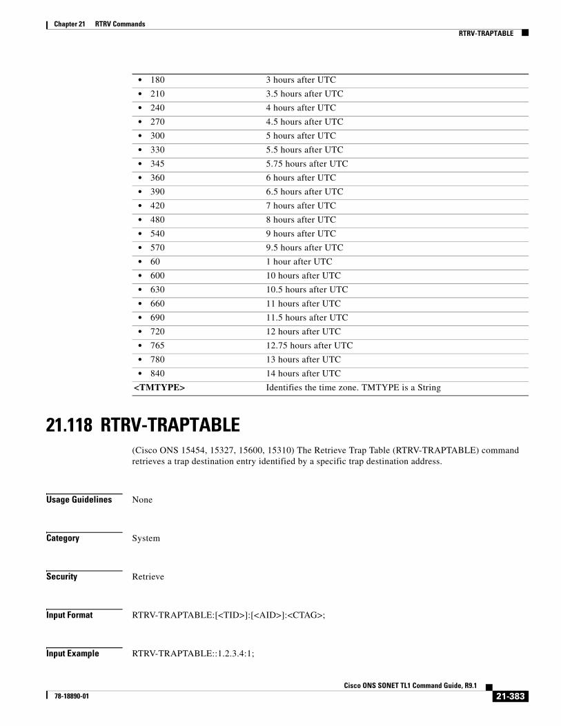
Chapter 21 RTRV CommandsRTRV-TRAPTABLE
21.118 RTRV-TRAPTABLE(Cisco ONS 15454, 15327, 15600, 15310) The Retrieve Trap Table (RTRV-TRAPTABLE) command retrieves a trap destination entry identified by a specific trap destination address.
Usage Guidelines None
Category System
Security Retrieve
Input Format RTRV-TRAPTABLE:[<TID>]:[<AID>]:<CTAG>;
Input Example RTRV-TRAPTABLE::1.2.3.4:1;
• 180 3 hours after UTC
• 210 3.5 hours after UTC
• 240 4 hours after UTC
• 270 4.5 hours after UTC
• 300 5 hours after UTC
• 330 5.5 hours after UTC
• 345 5.75 hours after UTC
• 360 6 hours after UTC
• 390 6.5 hours after UTC
• 420 7 hours after UTC
• 480 8 hours after UTC
• 540 9 hours after UTC
• 570 9.5 hours after UTC
• 60 1 hour after UTC
• 600 10 hours after UTC
• 630 10.5 hours after UTC
• 660 11 hours after UTC
• 690 11.5 hours after UTC
• 720 12 hours after UTC
• 765 12.75 hours after UTC
• 780 13 hours after UTC
• 840 14 hours after UTC
<TMTYPE> Identifies the time zone. TMTYPE is a String
21-383Cisco ONS SONET TL1 Command Guide, R9.1
78-18890-01

Chapter 21 RTRV CommandsRTRV-TRC-<OCN_BLSR>
Input Parameters
Output Format SID DATE TIMEM CTAG COMPLD “<DEST>,<TRAPPORT>,<COMMUNITY>,<SNMPVERSION>”;
Output Example TID-000 1998-06-20 14:30:00M 001 COMPLD “1.2.3.4,162,\“PRIVATE\”,SNMPV1”;
Output Parameters
21.119 RTRV-TRC-<OCN_BLSR>(Cisco ONS 15454 and ONS 15600) The Retrieve Trace Client for OC12, OC192, OC48, or OC768 (RTRV-TRC-<OCN_BLSR>) command retrieves the valid J1 expected trace string, retrieved trace string, trace mode, C2 byte, and STS bandwidth of the OC-N port only if the port has a BLSR.
Usage Guidelines • See Table 28-1 on page 1 for supported modifiers by platform.
• This command only applies to OC48AS and OC192 cards.
• Sending this command over unsupported BLSR path trace cards, or unequipped cards will result in a J1 Trace Not Supported On This Card (IIAC) error.
Category BLSR
Security Retrieve
<AID> Access identifier from the “26.16 IPADDR” section on page 39. IP address identifying the trap destination. Only a numeric IP address is allowed. A null value is equivalent to ALL.
<DEST> Access identifier from the “26.16 IPADDR” section on page 39.
<TRAPPORT> UDP port number associated with the trap destination. Defaults to 162. Integer
<COMMUNITY> Community name associated to the trap destination. Maximum of 32 characters. COMMUNITY is a string.
<SNMPVERSION> SNMP version number. Defaults to SNMPv1. The parameter type is SNMP_VERSION, which is the SNMP version.
• SNMPV1 SNMP version 1 (default)
• SNMPV2 SNMP version 2
21-384Cisco ONS SONET TL1 Command Guide, R9.1
78-18890-01

Chapter 21 RTRV CommandsRTRV-TRC-<OCN_BLSR>
Input Format RTRV-TRC-<OCN_BLSR>:[<TID>]:<AID>:<CTAG>[::::];
Input Example RTRV-TRC-OC48:CISCO:FAC-6-1:238;
Input Parameters
Output Format SID DATE TIMEM CTAG COMPLD “<AID>::[LEVEL=<LEVEL>],[EXPTRC=<EXPTRC>],[INCTRC=<INCTRC>], [TRCMODE=<TRCMODE>],[C2=<C2>]”;
Output Example TID-000 1998-06-20 14:30:00M 001 COMPLD “STS-6-1-25::LEVEL=STS1,EXPTRC=“EXPTRCSTRING”,INCTRC=“INCTRCSTRING”, TRCMODE=AUTO,C2=0X04”;
Output Parameters
<AID> Access identifier from the “26.15 FACILITY” section on page 35.
<AID> Access identifier from the “26.25 STS” section on page 45.
<LEVEL> (Optional) The rate of the cross-connect. The parameter type is STS_PATH, which is the modifier for some STS commands.
• STS1 Synchronous Transport Signal level 1 (51 Mbps)
• STS12C Synchronous Transport Signal level 12 Concatenated (622 Mbps)
• STS18C Synchronous Transport Signal level 18 Concatenated (933 Mbps)
• STS192C Synchronous Transport Signal level 192 (9952 Mbps)
• STS24C Synchronous Transport Signal level 24 Concatenated (1240 Mbps)
• STS36C Synchronous Transport Signal level 36 Concatenated (1866 Mbps)
• STS3C Synchronous Transport Signal level 3 Concatenated (155 Mbps)
• STS48C Synchronous Transport Signal level 48 Concatenated (2488 Mbps)
• STS6C Synchronous Transport Signal level 3 Concatenated (310 Mbps)
• STS9C Synchronous Transport Signal level 9 Concatenated (465 Mbps)
<EXPTRC> (Optional) Expected path trace content. Indicates the expected path trace message (J1) contents. EXPTRC is any 64-character ASCII string, including the terminating CR (carriage return) and LF (line feed). EXPTRC is a string.
<INCTRC> (Optional) The incoming path trace message contents. INCTRC is any combination of 64 characters including CR and LF. INCTRC is a string.
<TRCMODE> (Optional) Trace mode. The parameter type is TRCMODE (trace mode).
21-385Cisco ONS SONET TL1 Command Guide, R9.1
78-18890-01

Chapter 21 RTRV CommandsRTRV-TRC-<OCN_BLSR>
• AUTO Use the previously received path trace string as the expected string. Not applicable to MXP/TXP cards.
• AUTO-NO-AIS Use the previously received path trace string as the expected string and do not turn on AIS and RDI if TIM-P is detected.
• MAN Use the provisioned expected string as the expected string
• MAN-NO-AIS Use the provisioned expected string as the expected string and do not turn on AIS and RDI if TIM-P is detected.
• OFF Turn off path trace capability. Nothing will be reported
<C2> (Optional) The C2 byte hex code. Applicable only to STS-level paths in SONET (STSn). The parameter type is C2_BYTE, which is the C2 byte hex code.
• 0X00 Unequipped
• 0X01 Equipped-Non Specific payload
• 0X02 VT-Structured STS-1 SPE
• 0X03 Locked VT Mode
• 0X04 Asynchronous Mapping for DS3
• 0X12 Asynchronous Mapping for DS4NA
• 0X13 Mapping for ATM
• 0X14 Mapping for DQDB
• 0X15 Asynchronous Mapping for FDDI
• 0X16 HDLC-Over-SONET Mapping
• 0XE1 VT-structured STS-1 SPE with 1VTx payload defect
• 0XE2 VT-structured STS-1 SPE with 2VTx payload defects
• 0XE3 VT-structured STS-1 SPE with 3VTx payload defects
• 0XE4 VT-structured STS-1 SPE with 4VTx payload defects
• 0XE5 VT-structured STS-1 SPE with 5VTx payload defects
• 0XE6 VT-structured STS-1 SPE with 6VTx payload defects
• 0XE7 VT-structured STS-1 SPE with 7VTx payload defects
• 0XE8 VT-structured STS-1 SPE with 8VTx payload defects
• 0XE9 VT-structured STS-1 SPE with 9VTx payload defects
• 0XEA VT-structured STS-1 SPE with 10VTx payload defects
• 0XEB VT-structured STS-1 SPE with 11VTx payload defects
• 0XEC VT-structured STS-1 SPE with 12VTx payload defects
• 0XED VT-structured STS-1 SPE with 13VTx payload defects
• 0XEE VT-structured STS-1 SPE with 14VTx payload defects
• 0XEF VT-structured STS-1 SPE with 15VTx payload defects
• 0XF0 VT-structured STS-1 SPE with 16VTx payload defects
• 0XF1 VT-structured STS-1 SPE with 17VTx payload defects
• 0XF2 VT-structured STS-1 SPE with 18VTx payload defects
• 0XF3 VT-structured STS-1 SPE with 19VTx payload defects
• 0XF4 VT-structured STS-1 SPE with 20VTx payload defects
• 0XF5 VT-structured STS-1 SPE with 21VTx payload defects
21-386Cisco ONS SONET TL1 Command Guide, R9.1
78-18890-01

Chapter 21 RTRV CommandsRTRV-TRC-OCH
21.120 RTRV-TRC-OCH(Cisco ONS 15454) The Retrieve Trace Optical Channel (RTRV-TRC-OCH) command retrieves the sent trace string, expected trace string, received trace string, trace mode, and the trace level for the SONET J0 Section, the TTI PATH and SECTION monitoring levels of the DWDM facility.
Usage Guidelines The following rules apply:
• Client port–only the J0 Section trace applies.
• The J0 Section trace applies only if the card termination mode is not transparent and the payload is SONET.
• On the DWDM port, the J0 Section trace, the TTI Path, Section trace monitoring point traces are allowed.
• The J0 Section trace is allowed only if the payload for the card is set to SONET.
• The J0 Section trace is allowed only if the card termination mode is not transparent.
• The TTI Path, Section trace is allowed only if the ITU-T G.709 (DWRAP) is enabled.
Depending on the settings, the following filtering applies:
• If no TRCLEVEL is provided, all TRCLEVELs are reported as applicable.
• If TRCLEVEL is provided and no MSGTYPE is provided, all applicable MSGTYPEs for the given level are displayed.
• If no MSGTYPE is provided, all MSGTYPEs are reported as applicable.
• If a MSGTYPE is provided with out a TRCLEVEL, then the given MSGTYPE for all TRCLEVELs are displayed.
Category DWDM
Security Retrieve
• 0XF6 VT-structured STS-1 SPE with 22VTx payload defects
• 0XF7 VT-structured STS-1 SPE with 23VTx payload defects
• 0XF8 VT-structured STS-1 SPE with 24VTx payload defects
• 0XF9 VT-structured STS-1 SPE with 25VTx payload defects
• 0XFA VT-structured STS-1 SPE with 26VTx payload defects
• 0XFB VT-structured STS-1 SPE with 27VTx payload defects
• 0XFC VT-structured STS-1 SPE with 28VTx payload defects
• 0XFE O.181 Test Signal (TSS1 to TSS3) Mapping
• 0XFF Reserved, however, C2 is 0XFF if AIS-L is being generated by an optical card or cross-connect downstream.
21-387Cisco ONS SONET TL1 Command Guide, R9.1
78-18890-01

Chapter 21 RTRV CommandsRTRV-TRC-OCH
Input Format RTRV-TRC-OCH:[<TID>]:<SRC>:<CTAG>::[<MSGTYPE>],[<TRCLEVEL>][::];
Input Example RTRV-TRC-OCH:CISCO:CHAN-2-2:100::EXPTRC,TTI-PM;
Input Parameters
Output Format SID DATE TIMEM CTAG COMPLD “<CHANNEL>,<MOD>::[TRCLEVEL=<TRCLEVEL>],[EXPTRC=<EXPTRC>], [TRC=<TRC>],[INCTRC=<INCTRC>],[TRCMODE=<TRCMODE>], [TRCFORMAT=<TRCFORMAT>]”;
Output Example TID-000 1998-06-20 14:30:00M 001 COMPLD “CHAN-2-2,OCH::TRCLEVEL=TTI-PM,EXPTRC=\“AAA\”,TRC=\“AAA\”, INCTRC=\“AAA\”,TRCMODE=MAN,TRCFORMAT=64-BYTE”;
Output Parameters
<SRC> Access identifier from the “26.8 CHANNEL” section on page 19.
<MSGTYPE> Type of autonomous message to be retrieved. A null value is equivalent to ALL. The parameter type is MSGTYPE, which is the type of trace message.
• EXPTRC Expected incoming path trace message
• INCTRC Incoming path trace message
• TRC Outgoing path trace message
<TRCLEVEL> The trace level to be managed. A null value is equivalent to ALL. The parameter type is TRCLEVEL, which is the trace mode options.
• J0 Identifies the SONET J0 Section trace level
• TTI-PM Identifies the TTI Path monitoring point
• TTI-SM Identifies the TTI Section monitoring point
<CHANNEL> Access identifier from the “26.8 CHANNEL” section on page 19.
<MOD> Indicates an OCH AID type. The parameter type is MOD2, which is the line/path modifier.
• 10GFC 10-Gigabit Fibre Channel payload
• 10GFICON 10-Gigabit fiber connectivity payload
• 1GFC 1-Gigabit Fibre Channel payload
• 1GFICON 1-Gigabit fiber connectivity payload
• 1GISC3 1-Gigabit ISC3 compatible
• 2GFC 2-Gigabit Fibre Channel payload
• 2GFICON 2-Gigabit fiber connectivity payload
• 2GISC3 2-Gigabit ISC3 compatible
21-388Cisco ONS SONET TL1 Command Guide, R9.1
78-18890-01

Chapter 21 RTRV CommandsRTRV-TRC-OCH
• 4GFC 4-Gigabit Fibre Channel payload
• 4GFICON 4-Gigabit fiber connectivity payload
• 5GIB 5Gbps InfiniBand payload
• 8GFC 8-Gigabit Fibre Channel payload
• 40GIGE 40-Gigabit Ethernet
• D1VIDEO D1 video
• DS1 DS1 line of a DS3XM card
• DS3I DS3I line
• DV6000 DV6000
• EC1 EC1 facility
• ESCON ESCON
• ETRCLO ETRCLO
• FSTE FSTE facility
• G1000 G1000 facility
• GFPOS GFP over POS. Virtual ports partitioned using GFP’s multiplexing capability.
• GIGE Gigabit Ethernet
• HDTV HDTV
• ISC3PEER1G 1 Gbps ISC3 Peer
• ISC3PEER2G 2 Gbps ISC3 Peer
• ISC3PEER2R 1 Gbps or 2 Gbps ISC3 peer used in transparent (2R) mode
• ISCCOMPAT 1 Gbps ISC1, ISC2, and ISC3 compatibility
• OC3 OC-3 facility
• OC12 OC-12 facility
• OC48 OC-48 facility
• OC192 OC-192 facility
• OC768 OC-768 facility
• OCH Optical Channel
• OCHCC OCH client connection
• OCHNC OCH network connection
• OCHTERM OCH termination
• OMS Optical Multiplex Section
• OTS Optical Transport Section
• OTU3 Optical Transport Unit Level 3
• POS POS port
• STS1 STS1 path
• STS3C STS3c path
• STS6C STS6c path
• STS9C STS9c path
• STS18C STS18c path
• STS12C STS12c path
• STS24C STS24c path
21-389Cisco ONS SONET TL1 Command Guide, R9.1
78-18890-01
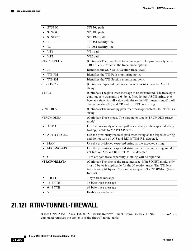
Chapter 21 RTRV CommandsRTRV-TUNNEL-FIREWALL
21.121 RTRV-TUNNEL-FIREWALL(Cisco ONS 15454, 15327, 15600, 15310) The Retrieve Tunnel Firewall (RTRV-TUNNEL-FIREWALL) command retrieves the contents of the firewall tunnel table.
• STS36C STS36c path
• STS48C STS48c path
• STS192C STS192c path
• T1 T1/DS1 facility/line
• T3 T1/DS1 facility/line
• VT1 VT1 path
• VT2 VT2 path
<TRCLEVEL> (Optional) The trace level to be managed. The parameter type is TRCLEVEL, which is the trace mode options.
• J0 Identifies the SONET J0 Section trace level.
• TTI-PM Identifies the TTI Path monitoring point.
• TTI-SM Identifies the TTI Section monitoring point.
<EXPTRC> (Optional) Expected path trace content. A 64 character ASCII string.
<TRC> (Optional) The path trace message to be transmitted. The trace byte continuously transmits a 64 byte, fixed length ASCII string, one byte at a time. A null value defaults to the NE transmitting 62 null characters (hex 00) and CR and LF. TRC is a string.
<INCTRC> (Optional) The incoming path trace message contents. INCTRC is a string.
<TRCMODE> (Optional) Trace mode. The parameter type is TRCMODE (trace mode).
• AUTO Use the previously received path trace string as the expected string. Not applicable to MXP/TXP cards.
• AUTO-NO-AIS Use the previously received path trace string as the expected string and do not turn on AIS and RDI if TIM-P is detected.
• MAN Use the provisioned expected string as the expected string.
• MAN-NO-AIS Use the provisioned expected string as the expected string and do not turn on AIS and RDI if TIM-P is detected.
• OFF Turn off path trace capability. Nothing will be reported.
<TRCFORMAT> (Optional) The size of the trace message. If in SONET mode, only 1 or 16 bytes is applicable for the J0 section trace. The TTI level trace is only 64 bytes. The parameter type is TRCFORMAT (trace format).
• 1-BYTE 1 byte trace message
• 16-BYTE 16 byte trace message
• 64-BYTE 64 byte trace message
• Y Enable an attribute.
21-390Cisco ONS SONET TL1 Command Guide, R9.1
78-18890-01

Chapter 21 RTRV CommandsRTRV-TUNNEL-PROXY
Usage Guidelines None
Category System
Security Retrieve
Input Format RTRV-TUNNEL-FIREWALL:[<TID>]::<CTAG>;
Input Example RTRV-TUNNEL-FIREWALL:TID::CTAG;
Input Parameters None that require description
Output Format SID DATE TIMEM CTAG COMPLD “[SRC ADDR=<SRCADDR>],[SRC MASK=<SRCMASK>],[DEST ADDR=<DESTADDR>], [DEST MASK=<DESTMASK>]”;
Output Example TID-000 1998-06-20 14:30:00M 001 COMPLD “SRC ADDR=64.101.150.10,SRC MASK=255.255.255.0,DEST ADDR=64.101.144.7, DEST MASK=255.255.255.0”;
Output Parameters
21.122 RTRV-TUNNEL-PROXY(Cisco ONS 15454, 15327, 15600, 15310) The Retrieve Tunnel Proxy command retrieves the contents of the proxy tunnel table.
Usage Guidelines None
<SRCADDR> (Optional) Source IP address. SRCADDR is a string.
<SRCMASK> (Optional) Source mask. SRCMASK is a string.
<DESTADDR> (Optional) Destination IP address. DESTADDR is a string.
<DESTMASK> (Optional) Destination mask. DESTMASK is a string.
21-391Cisco ONS SONET TL1 Command Guide, R9.1
78-18890-01

Chapter 21 RTRV CommandsRTRV-USER-SECU
Category System
Security Retrieve
Input Format RTRV-TUNNEL-PROXY:[<TID>]::<CTAG>;
Input Example RTRV-TUNNEL-PROXY:TID::CTAG;
Input Parameters None that require descriptions
Output Format SID DATE TIMEM CTAG COMPLD “[SRC ADDR=<SRCADDR>],[SRC MASK=<SRCMASK>],[DEST ADDR=<DESTADDR>], [DEST MASK=<DESTMASK>]”;
Output Example TID-000 1998-06-20 14:30:00M 001 COMPLD “SRC ADDR=64.101.150.10,SRC MASK=255.255.255.0,DEST ADDR=64.101.144.7, DEST MASK=255.255.255.0”;
Output Parameters
21.123 RTRV-USER-SECU(Cisco ONS 15454, 15327, 15600, 15310) The Retrieve User Security (RTRV-USER-SECU) command retrieves the security information of a specified user or list of users. The keyword ALL can be used to obtain a list of all users. For security reasons the password cannot be retrieved.
Usage Guidelines A Superuser can retrieve any user’s security information. A user with MAINT, PROV, or RTRV privileges can only retrieve their own information.
<SRCADDR> (Optional) Source IP address. SRCADDR is a string.
<SRCMASK> (Optional) Source mask. SRCMASK is a string.
<DESTADDR> (Optional) Destination IP address. DESTADDR is a string.
<DESTMASK> (Optional) Destination mask. DESTMASK is a string.
21-392Cisco ONS SONET TL1 Command Guide, R9.1
78-18890-01

Chapter 21 RTRV CommandsRTRV-USER-SECU
Note When using the keyword ALL, all users created for the system are displayed. This includes users created outside of the TL1 environment (for example, user IDs and passwords greater than 10 characters in length). Although displayed by the RTRV-USER-SECU command, these users will not be able to log into the TL1 environment.
Category Security
Security Retrieve
Note Maintenance, Provisioning and Retrieve users can retrieve their own information only.
Input Format RTRV-USER-SECU:[<TID>]:<UID>:<CTAG>;
Input Example RTRV-USER-SECU::CISCO15:1;
Input Parameters
Output Format SID DATE TIMEM CTAG COMPLD “<UID>:,<PRIVILEGE>:LOGGEDIN=<LOGGEDIN>,[NUMSESSIONS=<NUMSESS>,] [LOCKEDOUT=<LOCKEDOUT>,][DISABLED=<DISABLED>]”;
Output Example TID-000 1998-06-20 14:30:00M 001 COMPLD “CISCO15:,SUPER:LOGGEDIN=YES,NUMSESSIONS=1,LOCKEDOUT=NO,DISABLED=NO”;
Output Parameters
<UID> User identifier. The user ID or the keyword ALL. A non-Superuser can only specify his own user ID. Must not be null. UID is a string.
<UID> User identifier. The user ID that was retrieved. UID is a string.
<PRIVILEGE> The privilege level of the user. The parameter type is PRIVILEGE, which is the security level.
• MAINT Maintenance security level. 60 minutes of idle time.
• PROV Provision security level. 30 minutes of idle time.
• RTRV Retrieve security level. Unlimited idle time.
• SUPER Superuser security level. 15 minutes of idle time.
21-393Cisco ONS SONET TL1 Command Guide, R9.1
78-18890-01

Chapter 21 RTRV CommandsRTRV-VCG
21.124 RTRV-VCG(Cisco ONS 15310-CL, Cisco ONS 15310-MA, and Cisco ONS 15454) The Retrieve Virtual Concatenation Group (RTRV-VCG) command retrieves all the attributes provisioned for a VCG.
Usage Guidelines None
Category VCAT
Security Retrieve
Input Format RTRV-VCG:[<TID>]:<SRC>:<CTAG>[::::];
Input Example RTRV-VCG:NODE1:FAC-1-1:1234;
Input Parameters
<LOGGEDIN> Indicates whether the user is logged in to the NE. The parameter type is YES_NO, which indicates whether the user’s password is about to expire, the user is logged into the NE, or the user is locked out of the NE.
• NO No
• YES Yes
<NUMSESS> (Optional) The number of times the user is logged into the NE. NUMSESS is an integer.
<LOCKEDOUT> (Optional) Indicates whether the user is locked out of the NE. The parameter type is YES_NO, which indicates whether the user’s password is about to expire, the user is logged into the NE, or the user is locked out of the NE.
• NO No
• YES Yes
<DISABLED> (Optional) Indicates if the user is disabled. The parameter type is YES_NO, which indicates whether the user’s password is about to expire, the user is logged into the NE, or the user is locked out of the NE.
• NO No
• YES Yes
<SRC> Source access identifier from the “26.15 FACILITY” section on page 35. ML1000-2 and ML100T-12 cards use the VFAC AID. The FC_MR-4 card uses the FAC AID.
21-394Cisco ONS SONET TL1 Command Guide, R9.1
78-18890-01

Chapter 21 RTRV CommandsRTRV-VCG
Output Format SID DATE TIMEM CTAG COMPLD “<SRC>::TYPE=<TYPE>,TXCOUNT=<TXCOUNT>,CCT=<CCT>,[LCAS=<LCAS>], [BUFFERS=<BUFFERS>],[NAME=<NAME>]:<PST>”;
Output Example TID-000 1998-06-20 14:30:00M 001 COMPLD “FAC-1-1::TYPE=STS3C,TXCOUNT=8,CCT=2WAY,LCAS=LCAS,BUFFERS=DEFAULT, NAME=“VCG2”:IS”;
Output Parameters <SRC> Source access identifier from the “26.15 FACILITY” section on page 35. ML1000-2 and ML100T-12 cards use the VFAC AID. The FC_MR-4 card uses the FAC AID.
<TYPE> The type of the entity being provisioned. Null indicates not applicable. TYPE can be a CLEI code or another value. The type of member cross-connect. ML1000-2 and ML100T-12 cards support STS1, STS3c, and STS12c. The FC_MR-4 card supports STS3c only. The parameter type is MOD_PATH, which is the STS/VT path modifier.
• STS1 STS1 path
• STS12C STS12c path
• STS18C STS18c path
• STS192 STS192c path
• STS24C STS24c path
• STS36C STS36c path
• STS3C STS3c path
• STS48C STS48c path
• STS6C STS6c path
• STS9C STS9c path
• VT1 VT1 path
• VT2 VT2 path
<TXCOUNT> Number of VCG members in the transmit (Tx) direction. For ML1000-2 and ML100T-12 cards, the only valid value is 2. For the FC_MR-4 card, the only valid value is 8. TXCOUNT is an integer.
<CCT> Type of connection; one-way or two-way. Cross-connect type for the VCG member cross-connects. The parameter type is CCT, which is the type of cross-connect to be created.
• 1WAY A unidirectional connection from a source tributary to a destination tributary
• 1WAYDC Path Protection multicast drop with one-way continue
• 1WAYEN Path Protection multicast end node with one-way continue
21-395Cisco ONS SONET TL1 Command Guide, R9.1
78-18890-01

Chapter 21 RTRV CommandsRTRV-VLAN
21.125 RTRV-VLAN(Cisco ONS 15454) The Retrieve Virtual LAN (RTRV-VLAN) command retrieves a virtual LAN entry from the VLAN database. The VLAN database is a collection of VLANs used in an NE.
Usage Guidelines • If the AID is invalid, an IIAC (Invalid AID) error message is returned.
Category Ethernet
• 1WAYMON A bidirectional connection between the two tributaries
Note 1WAYMON is not supported with TL1. However, it is still supported from CTC. Using CTC, you can create 1WAYMON cross-connects that can be retrieved by TL1.
• 1WAYPCA A unidirectional connection from a source tributary to a destination tributary on the protection path/fiber
• 2WAY A bidirectional connection between the two tributaries
• 2WAYDC A bidirectional drop and continue connection applicable only to path protection traditional and integrated dual-ring interconnects
• 2WAYPCA A bidirectional connection between the two tributaries on the extra protection path/fiber
• DIAG Diagnostics cross-connect. Supports BERT (BLSR PCA diagnostics cross-connect).
<LCAS> (Optional) Link capacity adjustment scheme. The parameter type is LCAS, which is the link capacity adjustment scheme mode for the VCG created.
• LCAS LCAS is enabled.
• NONE No LCAS.
• SW-LCAS Supports the temporary removal of a VCG member during the member failure. Only supported by the ML1000-2 and ML100T-12 cards.
<BUFFERS> (Optional) Buffer type. The default value is DEFAULT. The FC_MR-4 card supports DEFAULT and EXPANDED buffers. Other data cards support DEFAULT buffers only. The parameter type is BUFFER_TYPE, which is the buffer type (used in VCAT).
• DEFAULT Default buffer value
• EXPANDED Expanded buffer value
<NAME> (Optional) Name of the VCAT group. NAME is a string.
<PST> (Optional) Primary state. The parameter type is PST, which indicates the current overall service condition of an entity.
• IS In Service
• OOS Out of Service
21-396Cisco ONS SONET TL1 Command Guide, R9.1
78-18890-01

Chapter 21 RTRV CommandsRTRV-VLAN-ETH
Security Retrieve
Input Format RTRV-VLAN:[<TID>]:<AID>:<CTAG>[::::];
Input Example RTRV-VLAN:ROCKS:VLAN-4096:1;
Input Parameters
Output Format SID DATE TIMEM CTAG COMPLD “<AID>::[NAME=<NAME>],[PROTN=<PROTN>]:”;
Output Example TID-000 1998-06-20 14:30:00M 001 COMPLD “VLAN-4096::NAME="MYVLAN",PROTN=Y:”;
Output Parameters
21.126 RTRV-VLAN-ETH(Cisco ONS 15454)
The VLAN attributes on a L2 ethernet port command retrieves the VLAN Profile associated to the couple L2 Ethernet pot - VLAN.
It retrieves also the Alarm status of a VLAN associated to a L2 ethernet port and the Multicast Mac address list.
Usage Guidelines This command accept the ALL AID.
<AID> The AID is used to access the VLAN.
• VLAN-{0-4096} The AID for a single VLAN. The value 0 is reserved for untagged VLANs.
<AID> Aid is used to access the VLAN.
• VLAN-{0-4096} The AID for a single VLAN. The value 0 is reserved for untagged VLANs.
<NAME> Indicates the VLAN name.
<PROTN> Indicates the VLAN protection (enabled or disabled).
• Y VLAN protection is enabled.
• N (Default) VLAN protection is disabled.
21-397Cisco ONS SONET TL1 Command Guide, R9.1
78-18890-01

Chapter 21 RTRV CommandsRTRV-VLAN-ETH
Category ETHERNET
Security Retrieve
Input Format RTRV-VLAN-ETH:[<TID>]:<aid>:<CTAG>::[<s_vlan_id>][::];
Input Example RTRV-VLAN-ETH:TID:ETH-1-1-1:CTAG::110;
Input Parameters
Output Format SID DATE TIMEM CTAG COMPLD"<aid>:<s_vlan_id>:[ALM=<alm_vlan>],[ALMDAT=<almdat>],[ALMTM=<almtm>],[BWP=<bwp>],[IGMPIP=<igmpip>][:]"; ;
Output Example TID-000 1998-06-20 14:30:00
M 001 COMPLD
"ETH-1-1-1:110:ALM=VLAN-AIS,ALMDAT=08-07,ALMTM=16-38-57,BWP=23:"; ;
Output Parameters
<AID> Ethernet aids are used to access L2 Ethernet ports.
• ALL The ALL aid is applicable for RTRV-only commands, basically the RTRV-rr type of commands. For e.g. RTRV-ETH with ALL aid returns all ETH ports on the node.
• ETH[-{1-30}]-{1-5,12-16}-{1-22}-1
Facility aid for GE-XP card in the format of:ETH-[shelf]-[slot]-[ppm]-[port]
• ETH[-{1-30}]-{1-6,12-17}-{1-4}-1
Facility aid for 10GE-XP card in the format of:ETH-[shelf]-[slot]-[ppm]-[port]
<SVLANID> This is the VLAN identifier. A VLAN ID is a number in the range 1..4096. The value of 0 is reserved to UNTAGged VLAN.This identifier is used for both CE (Customer) VLAN ID and S (Service Provider) VLAN ID.Default value is -
<AID> Ethernet aids are used to access L2 Ethernet ports.
ALL The ALL aid is applicable for RTRV-only commands, basically the RTRV-rr type of commands. For e.g. RTRV-ETH with ALL aid returns all ETH ports on the node.
• ETH[-{1-30}]-{1-5,12-16}-{1-22}-1
Facility aid for GE-XP card in the format of:ETH-[shelf]-[slot]-[ppm]-[port]
• ETH[-{1-30}]-{1-6,12-17}-{1-4}-1
Facility aid for 10GE-XP card in the format of:ETH-[shelf]-[slot]-[ppm]-[port]
21-398Cisco ONS SONET TL1 Command Guide, R9.1
78-18890-01

Chapter 21 RTRV CommandsRTRV-VT
21.127 RTRV-VT(Cisco ONS 15454) The Retrieve Virtual Tributary (RTRV-VT) command retrieves the attributes associated with a VT path based on the granularity level of NE- or slot-specific VTs.
Usage Guidelines • Supported AIDs are ALL, SLOT-N (N=1,2,...ALL), VT-<SLOT>[-<PORT>]-<STS NUMBER>-<VT GROUP>-<VT NUMBER>.
• The RVRTV, RVTM, HOLDOFFTIMER, and UPSRPTHSTATE parameters only apply to UPSR.
Category Paths
Security Retrieve
Input Format RTRV-VT:[<TID>]:<AID>:<CTAG>;
Input Example RTRV-VT:TID:VT1-1-1-1-1:1;
Input Parameters
Output Format SID DATE TIMEM CTAG COMPLD “<AID>::[LEVEL=<LEVEL>],[RVRTV=<RVRTV>],[RVTM=<RVTM>],
<SVLANID> This is the VLAN identifier. A VLAN ID is a number in the range 1..4096. The value of 0 is reserved to UNTAGged VLAN.This identifier is used for both CE (Customer) VLAN ID and S (Service Provider) VLAN ID.Default value is -
<ALM> This is used to represent the Vlan Alarm status
• VLAN-AIS Alarm condition indicating Vlan is lost
<ALMDAT> identifies the date. date is a String. Default value is - "current date"
<ALMTM> identifies the time. time is a String. Default value is - current time
<BWP> This is the BWP identifier. A BWP ID is a number in the range 0..10000. The value of 0 is reserved for the default profile that can't be edited nor delete. - Default value is 0
<IGMPIP> IGMP IP address. Is the Multicast IP address indicating the IGMP group activated on a L2 Ethernet port to provide multicast stream through a specific S-Vlan. Default value is -
<AID> Access identifier from the “26.2 AidUnionId” section on page 12.
21-399Cisco ONS SONET TL1 Command Guide, R9.1
78-18890-01

Chapter 21 RTRV CommandsRTRV-VT
[HOLDOFFTIMER=<HOLDOFFTIMER>],[TACC=<TACC>],[TAPTYPE=<TAPTYPE>], [UPSRPTHSTATE=<UPSRPTHSTATE>]:[<PST>],[<SST>]”;
Output Example TID-000 1998-06-20 14:30:00M 001 COMPLD “VT1-1-1-1-1-1::LEVEL=VT1,RVRTV=Y,RVTM=1.0,HOLDOFFTIMER=2000,TACC=8, TAPTYPE=SINGLE,UPSRPTHSTATE=ACT:OOS,AINS”;
Output Parameters <AID> Access identifier from the “26.2 AidUnionId” section on page 12.
<LEVEL> (Optional) The rate of the cross-connect. Indicates the rate of the cross-connected channel. Applicable only to VT1 path in SONET. The parameter type is VT_PATH, which is the modifier for some VT commands.
• VT1 Virtual Tributary 1
• VT2 Virtual Tributary 2
<RVRTV> (Optional) Revertive mode. The value Y indicates that protection switching system reverts service to the original line after restoration. The value N indicates that protection switching system does not revert service to the original line after restoration. RVRTV is applicable only for 1+1 protection switching. Null defaults to N. The parameter type is ON_OFF (disable or enable an attribute).
• N Does not revert service to original line after restoration.
• Y Reverts service to original line after restoration.
<RVTM> (Optional) Revertive time. Only applies to path protection. Defaults to empty because RVRTV is N when a path protection path is created. The parameter type is REVERTIVE_TIME.
• 0.5 to 12.0 Revertive time is 0.5 to 12.0 minutes.
<HOLDOFFTIMER> (Optional) Hold off timer. HOLDOFFTIMER is an integer.
<TACC> (Optional) Test access. Indicates whether the digroup being provisioned is to be used as a test access digroup. Defaults to N.
<TAPTYPE> (Optional) TAP type. The parameter type is TAPTYPE, which is the test access point type.
• DUAL Dual FAD
• SINGLE Single FAD
<UPSRPTHSTATE> (Optional) Indicates whether a given AID is the working or standby path of a path protection cross-connect. The parameter type is STATUS, which is the status of the unit in the protection pair.
• ACT The entity is the active unit in the shelf.
• NA Status is unavailable.
• STBY The entity is the standby unit in the shelf.
<PST> Primary state. The parameter type is PST, which indicates the current overall service condition of an entity.
• IS In Service
21-400Cisco ONS SONET TL1 Command Guide, R9.1
78-18890-01

Chapter 21 RTRV CommandsRTRV-WDMANS
21.128 RTRV-WDMANS(Cisco ONS 15454) The Retrieve Wavelength Division Multiplexing Automatic Node Setup (RTRV-WDMANS) command edits the Automatic Optical Node Setup (AONS) application attributes.
Usage Guidelines None
Category DWDM
Security Maintenance
Input Format RTRV-WDMANS:[<TID>]:<AID>:<CTAG>:[<WLEN>]:;
Input Example RTRV-WDMANS::LINE-1-13-2-TX:77::1530.33;
Input Parameters
• OOS Out of Service
<SST> Secondary state. The parameter type is SST, which provides additional information pertaining to PST and PSTQ.
• AINS Automatic In-Service
• DSBLD Disabled
• LPBK Loopback
• MEA Mismatch of Equipment
• MT Maintenance
• OOG Out of Group
• SWDL Software Download
• UAS Unassigned
• UEQ Unequipped
<AID> The AID is used to access the WDM node or a single port of the DWDM node.
• WDMNODE Indicates the WDM node of an MSTP and accesses the NTWTYPE and DITHER WDMANS node parameters.
• LINE The optical transport section port.
• BAND The optical multiplex section port.
• CHAN The optical channel port.
21-401Cisco ONS SONET TL1 Command Guide, R9.1
78-18890-01
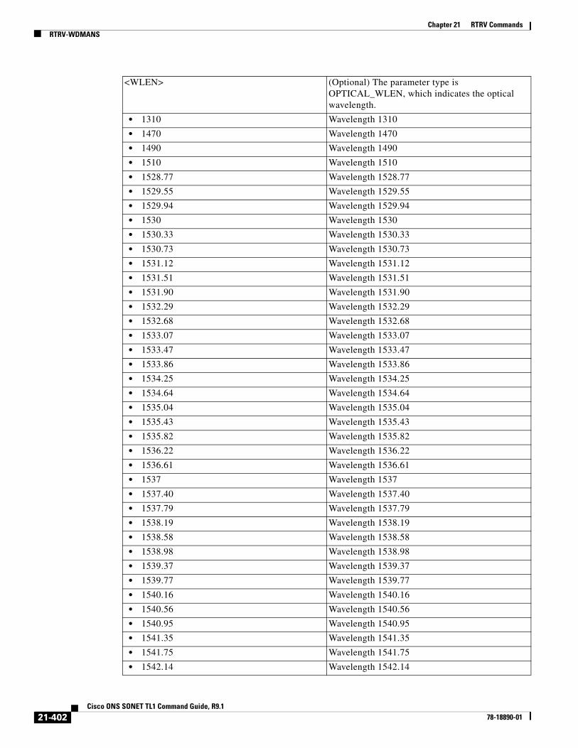
Chapter 21 RTRV CommandsRTRV-WDMANS
<WLEN> (Optional) The parameter type is OPTICAL_WLEN, which indicates the optical wavelength.
• 1310 Wavelength 1310
• 1470 Wavelength 1470
• 1490 Wavelength 1490
• 1510 Wavelength 1510
• 1528.77 Wavelength 1528.77
• 1529.55 Wavelength 1529.55
• 1529.94 Wavelength 1529.94
• 1530 Wavelength 1530
• 1530.33 Wavelength 1530.33
• 1530.73 Wavelength 1530.73
• 1531.12 Wavelength 1531.12
• 1531.51 Wavelength 1531.51
• 1531.90 Wavelength 1531.90
• 1532.29 Wavelength 1532.29
• 1532.68 Wavelength 1532.68
• 1533.07 Wavelength 1533.07
• 1533.47 Wavelength 1533.47
• 1533.86 Wavelength 1533.86
• 1534.25 Wavelength 1534.25
• 1534.64 Wavelength 1534.64
• 1535.04 Wavelength 1535.04
• 1535.43 Wavelength 1535.43
• 1535.82 Wavelength 1535.82
• 1536.22 Wavelength 1536.22
• 1536.61 Wavelength 1536.61
• 1537 Wavelength 1537
• 1537.40 Wavelength 1537.40
• 1537.79 Wavelength 1537.79
• 1538.19 Wavelength 1538.19
• 1538.58 Wavelength 1538.58
• 1538.98 Wavelength 1538.98
• 1539.37 Wavelength 1539.37
• 1539.77 Wavelength 1539.77
• 1540.16 Wavelength 1540.16
• 1540.56 Wavelength 1540.56
• 1540.95 Wavelength 1540.95
• 1541.35 Wavelength 1541.35
• 1541.75 Wavelength 1541.75
• 1542.14 Wavelength 1542.14
21-402Cisco ONS SONET TL1 Command Guide, R9.1
78-18890-01

Chapter 21 RTRV CommandsRTRV-WDMANS
• 1542.35 Wavelength 1542.35
• 1542.54 Wavelength 1542.54
• 1542.94 Wavelength 1542.94
• 1543.33 Wavelength 1543.33
• 1543.73 Wavelength 1543.73
• 1544.13 Wavelength 1544.13
• 1544.53 Wavelength 1544.53
• 1544.92 Wavelength 1544.92
• 1545.32 Wavelength 1545.32
• 1545.72 Wavelength 1545.72
• 1546.12 Wavelength 1546.12
• 1546.52 Wavelength 1546.52
• 1546.92 Wavelength 1546.92
• 1547.32 Wavelength 1547.32
• 1547.72 Wavelength 1547.72
• 1548.12 Wavelength 1548.12
• 1548.51 Wavelength 1548.51
• 1548.92 Wavelength 1548.92
• 1549.32 Wavelength 1549.32
• 1549.71 Wavelength 1549.71
• 1550 Wavelength 1500
• 1550.12 Wavelength 1550.12
• 1550.52 Wavelength 1550.52
• 1550.92 Wavelength 1550.92
• 1551.32 Wavelength 1551.32
• 1551.72 Wavelength 1551.72
• 1552.12 Wavelength 1552.12
• 1552.52 Wavelength 1552.52
• 1552.93 Wavelength 1552.93
• 1553.33 Wavelength 1553.33
• 1553.73 Wavelength 1553.73
• 1554.13 Wavelength 1554.13
• 1554.13 Wavelength 1554.13
• 1554.94 Wavelength 1554.94
• 1555.34 Wavelength 1555.34
• 1555.75 Wavelength 1555.75
• 1556.15 Wavelength 1556.15
• 1556.55 Wavelength 1556.55
• 1556.96 Wavelength 1556.96
• 1557.36 Wavelength 1557.36
• 1557.77 Wavelength 1557.77
21-403Cisco ONS SONET TL1 Command Guide, R9.1
78-18890-01

Chapter 21 RTRV CommandsRTRV-WDMANS
• 1558.17 Wavelength 1558.17
• 1558.58 Wavelength 1558.58
• 1558.98 Wavelength 1558.98
• 1559.39 Wavelength 1559.39
• 1559.79 Wavelength 1559.79
• 1560.20 Wavelength 1560.20
• 1560.61 Wavelength 1560.61
• 1561.01 Wavelength 1561.01
• 1561.42 Wavelength 1561.42
• 1561.83 Wavelength 1561.83
• 1570 Wavelength 1570
• 1570.83 Wavelength 1570.83
• 1571.24 Wavelength 1571.24
• 1571.65 Wavelength 1571.65
• 1572.06 Wavelength 1572.06
• 1572.48 Wavelength 1572.48
• 1572.89 Wavelength 1572.89
• 1573.30 Wavelength 1573.30
• 1573.71 Wavelength 1573.71
• 1574.13 Wavelength 1574.13
• 1574.54 Wavelength 1574.54
• 1574.95 Wavelength 1574.95
• 1575.37 Wavelength 1575.37
• 1575.78 Wavelength 1575.78
• 1576.20 Wavelength 1576.20
• 1576.61 Wavelength 1576.61
• 1577.03 Wavelength 1577.03
• 1577.44 Wavelength 1577.44
• 1577.86 Wavelength 1577.86
• 1578.27 Wavelength 1578.27
• 1578.69 Wavelength 1578.69
• 1579.10 Wavelength 1579.10
• 1579.52 Wavelength 1579.52
• 1579.93 Wavelength 1579.93
• 1580.35 Wavelength 1580.35
• 1580.77 Wavelength 1580.77
• 1581.18 Wavelength 1581.18
• 1581.60 Wavelength 1581.60
• 1582.02 Wavelength 1582.02
• 1582.44 Wavelength 1582.44
• 1582.85 Wavelength 1582.85
21-404Cisco ONS SONET TL1 Command Guide, R9.1
78-18890-01

Chapter 21 RTRV CommandsRTRV-WDMANS
• 1583.27 Wavelength 1583.27
• 1583.69 Wavelength 1583.69
• 1584.11 Wavelength 1584.11
• 1584.53 Wavelength 1584.53
• 1584.95 Wavelength 1584.95
• 1585.36 Wavelength 1585.36
• 1585.78 Wavelength 1585.78
• 1586.20 Wavelength 1586.20
• 1586.62 Wavelength 1586.62
• 1587.04 Wavelength 1587.04
• 1587.46 Wavelength 1587.46
• 1587.88 Wavelength 1587.88
• 1588.30 Wavelength 1588.30
• 1588.73 Wavelength 1588.73
• 1589.15 Wavelength 1589.15
• 1589.57 Wavelength 1589.57
• 1589.99 Wavelength 1589.99
• 1590 Wavelength 1590
• 1590.41 Wavelength 1590.41
• 1590.83 Wavelength 1590.83
• 1591.26 Wavelength 1591.26
• 1591.68 Wavelength 1591.68
• 1592.10 Wavelength 1592.10
• 1592.52 Wavelength 1592.52
• 1592.95 Wavelength 1592.95
• 1593.37 Wavelength 1593.37
• 1593.79 Wavelength 1593.79
• 1594.22 Wavelength 1594.22
• 1594.64 Wavelength 1594.64
• 1595.06 Wavelength 1595.06
• 1595.49 Wavelength 1595.49
• 1596.34 Wavelength 1596.34
• 1596.76 Wavelength 1596.76
• 1597.19 Wavelength 1597.19
• 1597.62 Wavelength 1597.62
• 1598.04 Wavelength 1598.04
• 1598.47 Wavelength 1598.47
• 1598.89 Wavelength 1598.89
• 1599.32 Wavelength 1599.32
• 1599.75 Wavelength 1599.75
• 1600.06 Wavelength 1600.06
21-405Cisco ONS SONET TL1 Command Guide, R9.1
78-18890-01
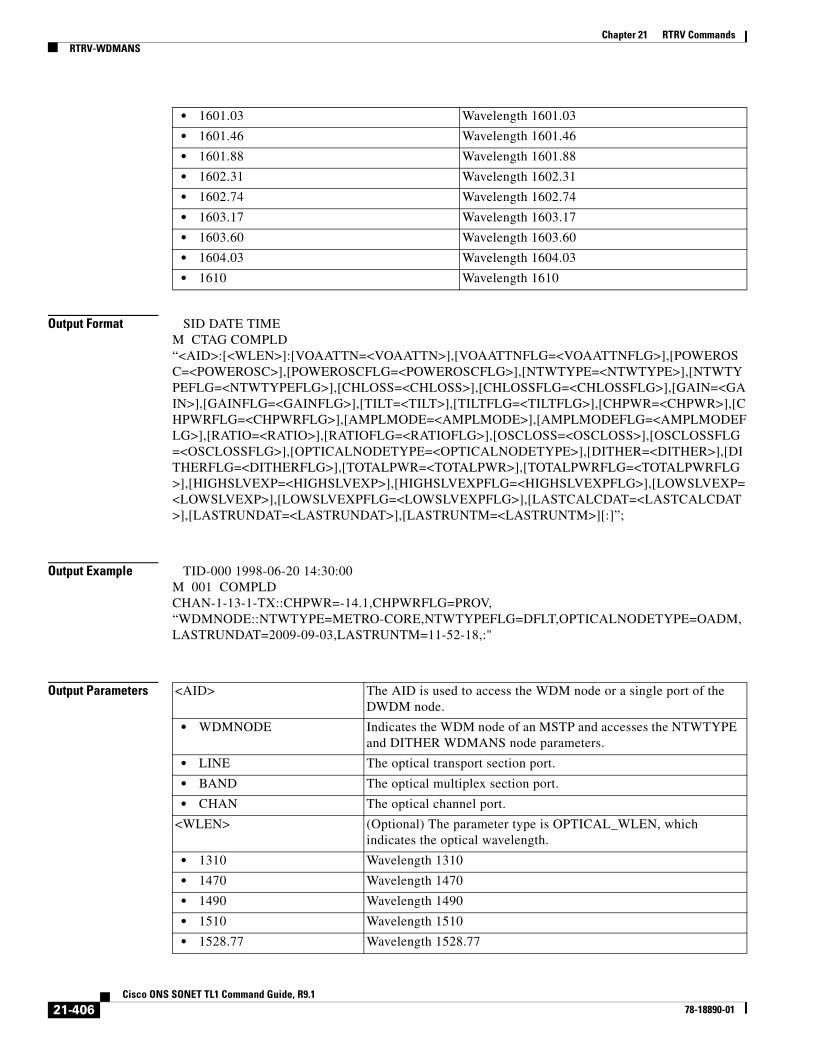
Chapter 21 RTRV CommandsRTRV-WDMANS
Output Format SID DATE TIMEM CTAG COMPLD“<AID>:[<WLEN>]:[VOAATTN=<VOAATTN>],[VOAATTNFLG=<VOAATTNFLG>],[POWEROSC=<POWEROSC>],[POWEROSCFLG=<POWEROSCFLG>],[NTWTYPE=<NTWTYPE>],[NTWTYPEFLG=<NTWTYPEFLG>],[CHLOSS=<CHLOSS>],[CHLOSSFLG=<CHLOSSFLG>],[GAIN=<GAIN>],[GAINFLG=<GAINFLG>],[TILT=<TILT>],[TILTFLG=<TILTFLG>],[CHPWR=<CHPWR>],[CHPWRFLG=<CHPWRFLG>],[AMPLMODE=<AMPLMODE>],[AMPLMODEFLG=<AMPLMODEFLG>],[RATIO=<RATIO>],[RATIOFLG=<RATIOFLG>],[OSCLOSS=<OSCLOSS>],[OSCLOSSFLG=<OSCLOSSFLG>],[OPTICALNODETYPE=<OPTICALNODETYPE>],[DITHER=<DITHER>],[DITHERFLG=<DITHERFLG>],[TOTALPWR=<TOTALPWR>],[TOTALPWRFLG=<TOTALPWRFLG>],[HIGHSLVEXP=<HIGHSLVEXP>],[HIGHSLVEXPFLG=<HIGHSLVEXPFLG>],[LOWSLVEXP=<LOWSLVEXP>],[LOWSLVEXPFLG=<LOWSLVEXPFLG>],[LASTCALCDAT=<LASTCALCDAT>],[LASTRUNDAT=<LASTRUNDAT>],[LASTRUNTM=<LASTRUNTM>][:]”;
Output Example TID-000 1998-06-20 14:30:00M 001 COMPLDCHAN-1-13-1-TX::CHPWR=-14.1,CHPWRFLG=PROV,“WDMNODE::NTWTYPE=METRO-CORE,NTWTYPEFLG=DFLT,OPTICALNODETYPE=OADM,LASTRUNDAT=2009-09-03,LASTRUNTM=11-52-18,:"
Output Parameters
• 1601.03 Wavelength 1601.03
• 1601.46 Wavelength 1601.46
• 1601.88 Wavelength 1601.88
• 1602.31 Wavelength 1602.31
• 1602.74 Wavelength 1602.74
• 1603.17 Wavelength 1603.17
• 1603.60 Wavelength 1603.60
• 1604.03 Wavelength 1604.03
• 1610 Wavelength 1610
<AID> The AID is used to access the WDM node or a single port of the DWDM node.
• WDMNODE Indicates the WDM node of an MSTP and accesses the NTWTYPE and DITHER WDMANS node parameters.
• LINE The optical transport section port.
• BAND The optical multiplex section port.
• CHAN The optical channel port.
<WLEN> (Optional) The parameter type is OPTICAL_WLEN, which indicates the optical wavelength.
• 1310 Wavelength 1310
• 1470 Wavelength 1470
• 1490 Wavelength 1490
• 1510 Wavelength 1510
• 1528.77 Wavelength 1528.77
21-406Cisco ONS SONET TL1 Command Guide, R9.1
78-18890-01

Chapter 21 RTRV CommandsRTRV-WDMANS
• 1529.55 Wavelength 1529.55
• 1529.94 Wavelength 1529.94
• 1530 Wavelength 1530
• 1530.33 Wavelength 1530.33
• 1530.73 Wavelength 1530.73
• 1531.12 Wavelength 1531.12
• 1531.51 Wavelength 1531.51
• 1531.90 Wavelength 1531.90
• 1532.29 Wavelength 1532.29
• 1532.68 Wavelength 1532.68
• 1533.07 Wavelength 1533.07
• 1533.47 Wavelength 1533.47
• 1533.86 Wavelength 1533.86
• 1534.25 Wavelength 1534.25
• 1534.64 Wavelength 1534.64
• 1535.04 Wavelength 1535.04
• 1535.43 Wavelength 1535.43
• 1535.82 Wavelength 1535.82
• 1536.22 Wavelength 1536.22
• 1536.61 Wavelength 1536.61
• 1537 Wavelength 1537
• 1537.40 Wavelength 1537.40
• 1537.79 Wavelength 1537.79
• 1538.19 Wavelength 1538.19
• 1538.58 Wavelength 1538.58
• 1538.98 Wavelength 1538.98
• 1539.37 Wavelength 1539.37
• 1539.77 Wavelength 1539.77
• 1540.16 Wavelength 1540.16
• 1540.56 Wavelength 1540.56
• 1540.95 Wavelength 1540.95
• 1541.35 Wavelength 1541.35
• 1541.75 Wavelength 1541.75
• 1542.14 Wavelength 1542.14
• 1542.35 Wavelength 1542.35
• 1542.54 Wavelength 1542.54
• 1542.94 Wavelength 1542.94
• 1543.33 Wavelength 1543.33
• 1543.73 Wavelength 1543.73
• 1544.13 Wavelength 1544.13
• 1544.53 Wavelength 1544.53
21-407Cisco ONS SONET TL1 Command Guide, R9.1
78-18890-01

Chapter 21 RTRV CommandsRTRV-WDMANS
• 1544.92 Wavelength 1544.92
• 1545.32 Wavelength 1545.32
• 1545.72 Wavelength 1545.72
• 1546.12 Wavelength 1546.12
• 1546.52 Wavelength 1546.52
• 1546.92 Wavelength 1546.92
• 1547.32 Wavelength 1547.32
• 1547.72 Wavelength 1547.72
• 1548.12 Wavelength 1548.12
• 1548.51 Wavelength 1548.51
• 1548.92 Wavelength 1548.92
• 1549.32 Wavelength 1549.32
• 1549.71 Wavelength 1549.71
• 1550 Wavelength 1500
• 1550.12 Wavelength 1550.12
• 1550.52 Wavelength 1550.52
• 1550.92 Wavelength 1550.92
• 1551.32 Wavelength 1551.32
• 1551.72 Wavelength 1551.72
• 1552.12 Wavelength 1552.12
• 1552.52 Wavelength 1552.52
• 1552.93 Wavelength 1552.93
• 1553.33 Wavelength 1553.33
• 1553.73 Wavelength 1553.73
• 1554.13 Wavelength 1554.13
• 1554.13 Wavelength 1554.13
• 1554.94 Wavelength 1554.94
• 1555.34 Wavelength 1555.34
• 1555.75 Wavelength 1555.75
• 1556.15 Wavelength 1556.15
• 1556.55 Wavelength 1556.55
• 1556.96 Wavelength 1556.96
• 1557.36 Wavelength 1557.36
• 1557.77 Wavelength 1557.77
• 1558.17 Wavelength 1558.17
• 1558.58 Wavelength 1558.58
• 1558.98 Wavelength 1558.98
• 1559.39 Wavelength 1559.39
• 1559.79 Wavelength 1559.79
• 1560.20 Wavelength 1560.20
• 1560.61 Wavelength 1560.61
21-408Cisco ONS SONET TL1 Command Guide, R9.1
78-18890-01
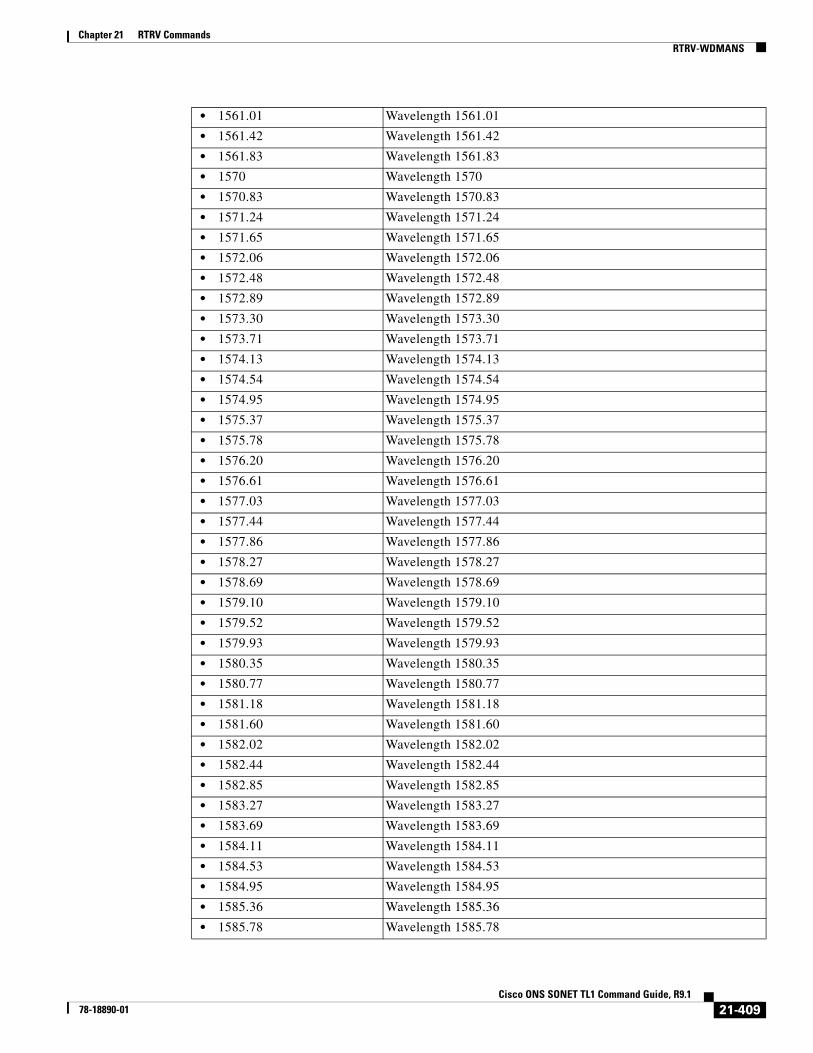
Chapter 21 RTRV CommandsRTRV-WDMANS
• 1561.01 Wavelength 1561.01
• 1561.42 Wavelength 1561.42
• 1561.83 Wavelength 1561.83
• 1570 Wavelength 1570
• 1570.83 Wavelength 1570.83
• 1571.24 Wavelength 1571.24
• 1571.65 Wavelength 1571.65
• 1572.06 Wavelength 1572.06
• 1572.48 Wavelength 1572.48
• 1572.89 Wavelength 1572.89
• 1573.30 Wavelength 1573.30
• 1573.71 Wavelength 1573.71
• 1574.13 Wavelength 1574.13
• 1574.54 Wavelength 1574.54
• 1574.95 Wavelength 1574.95
• 1575.37 Wavelength 1575.37
• 1575.78 Wavelength 1575.78
• 1576.20 Wavelength 1576.20
• 1576.61 Wavelength 1576.61
• 1577.03 Wavelength 1577.03
• 1577.44 Wavelength 1577.44
• 1577.86 Wavelength 1577.86
• 1578.27 Wavelength 1578.27
• 1578.69 Wavelength 1578.69
• 1579.10 Wavelength 1579.10
• 1579.52 Wavelength 1579.52
• 1579.93 Wavelength 1579.93
• 1580.35 Wavelength 1580.35
• 1580.77 Wavelength 1580.77
• 1581.18 Wavelength 1581.18
• 1581.60 Wavelength 1581.60
• 1582.02 Wavelength 1582.02
• 1582.44 Wavelength 1582.44
• 1582.85 Wavelength 1582.85
• 1583.27 Wavelength 1583.27
• 1583.69 Wavelength 1583.69
• 1584.11 Wavelength 1584.11
• 1584.53 Wavelength 1584.53
• 1584.95 Wavelength 1584.95
• 1585.36 Wavelength 1585.36
• 1585.78 Wavelength 1585.78
21-409Cisco ONS SONET TL1 Command Guide, R9.1
78-18890-01

Chapter 21 RTRV CommandsRTRV-WDMANS
• 1586.20 Wavelength 1586.20
• 1586.62 Wavelength 1586.62
• 1587.04 Wavelength 1587.04
• 1587.46 Wavelength 1587.46
• 1587.88 Wavelength 1587.88
• 1588.30 Wavelength 1588.30
• 1588.73 Wavelength 1588.73
• 1589.15 Wavelength 1589.15
• 1589.57 Wavelength 1589.57
• 1589.99 Wavelength 1589.99
• 1590 Wavelength 1590
• 1590.41 Wavelength 1590.41
• 1590.83 Wavelength 1590.83
• 1591.26 Wavelength 1591.26
• 1591.68 Wavelength 1591.68
• 1592.10 Wavelength 1592.10
• 1592.52 Wavelength 1592.52
• 1592.95 Wavelength 1592.95
• 1593.37 Wavelength 1593.37
• 1593.79 Wavelength 1593.79
• 1594.22 Wavelength 1594.22
• 1594.64 Wavelength 1594.64
• 1595.06 Wavelength 1595.06
• 1595.49 Wavelength 1595.49
• 1596.34 Wavelength 1596.34
• 1596.76 Wavelength 1596.76
• 1597.19 Wavelength 1597.19
• 1597.62 Wavelength 1597.62
• 1598.04 Wavelength 1598.04
• 1598.47 Wavelength 1598.47
• 1598.89 Wavelength 1598.89
• 1599.32 Wavelength 1599.32
• 1599.75 Wavelength 1599.75
• 1600.06 Wavelength 1600.06
• 1601.03 Wavelength 1601.03
• 1601.46 Wavelength 1601.46
• 1601.88 Wavelength 1601.88
• 1602.31 Wavelength 1602.31
• 1602.74 Wavelength 1602.74
• 1603.17 Wavelength 1603.17
• 1603.60 Wavelength 1603.60
21-410Cisco ONS SONET TL1 Command Guide, R9.1
78-18890-01

Chapter 21 RTRV CommandsRTRV-WDMANS
• 1604.03 Wavelength 1604.03
• 1610 Wavelength 1610
<VOAATTN> The value of calibrated attenuation for the VOA expressed in dBm. The range is 0.0 to +30.0. VOAATTN is a float.
<VOAATTNFLG> Status flag indicating the state of the WDMANS parameter.
<POWEROSC> WDM-ANS OSC power parameter.
<POWEROSCFLG> Status flag indicating the state of the WDMANS parameter.
<NTWTYPE> WDM-ANS network type parameter.
<NTWTYPEFLG> Status flag indicating the state of the WDMANS parameter.
<CHLOSS> WDM-ANS channel loss parameter.
<CHLOSSFLG> Status flag indicating the state of the WDMANS parameter.
<GAIN> WDM-ANS amplifier gain parameter.
<GAINFLG> Status flag indicating the state of the WDMANS parameter.
<TILT> WDM-ANS amplifier tilt parameter.
<TILTFLG> Status flag indicating the state of the WDMANS parameter.
<CHPWR> WDM-ANS channel power parameter.
<CHPWRFLG> Status flag indicating the state of the WDMANS parameter.
<AMPLMODE WDM-ANS amplifier mode parameter.
<AMPLMODEFLG> Status flag indicating the state of the WDMANS parameter.
<RATIO> WDM-ANS Raman amplifier pump ratio parameter.
<RATIOFLG> .Status flag indicating the state of the WDMANS parameter.
<OSCLOSS> WDM-ANS OSC channel loss parameter.
<OSCLOSSFLG> Status flag indicating the state of the WDMANS parameter.
<OPTICALNODETYPE> (Optional) The optical configuration type for the NE. The parameter type is OPTICAL_NODE_TYPE, which is the optical configuration types for NEs.
<DITHER> WDM-ANS WXC dithering parameter.
<DITHERFLG> Status flag indicating the state of the WDMANS parameter.
<TOTALPWR> WDM-ANS Raman amplifier total power in mW.
<TOTALPWRFLG> Status flag indicating the state of the WDMANS parameter.
<HIGHSLVEXP> Span loss verification—high value.
<HIGHSLVEXPFLG> Status flag indicating the state of the WDMANS parameter.
<LOWSLVEXP> Span loss verification—low value.
<LOWSLVEXPFLG> Status flag indicating the state of the WDMANS parameter.
<LASTRUNDAT> (Optional) The last date when the WDMANS application calculated the parameters. The format is MM-DD, where MM (month of year) ranges from 1 to 12 and DD (day of month) ranges from 1 to 31.
<LASTRUNTM> (Optional) The last time when the WDMANS application calculated the parameters. The format is HH-MM, where HH (hour of day) ranges from 1 to 23 and MM (minute of hour) ranges from 0 to 59.
21-411Cisco ONS SONET TL1 Command Guide, R9.1
78-18890-01

Chapter 21 RTRV CommandsRTRV-WDMSIDE
21.129 RTRV-WDMSIDE(Cisco ONS 15454) The Retrieve Wavelength Division Multiplexing Side (RTRV-WDMSIDE) command retrieves the WDM side and defines its attributes.
Usage Guidelines None
Category DWDM
Security Maintenance
Input Format RTRV-WDMSIDE:[<TID>]:<AID>:<CTAG>[::::];
Input Example RTRV-WDMSIDE:PENNGROVE:WDMSIDE-A:114;
Input Parameters
Output Format SID DATE TIMEM CTAG COMPLD “<AID>::LINEIN=<LINEIN>,LINEOUT=<LINEOUT>,[OCS=<OSC>][:]”;
Output Example TID-000 1998-06-20 14:30:00M 001 COMPLD “WDMSIDE-A::LINEIN=LINE-1-3-RX,LINEOUT=LINE-1-3-TX,OSC=FAC-8-1”;
<LASTCALCDAT> (Optional) The last date when the WDMANS application was run automatically or by user request. The format is MM-DD, where MM (month of year) ranges from 1 to 12 and DD (day of month) ranges from 1 to 31.
<LASTCALSTM> (Optional) The last time when the WDMANS application was run automatically or by user request. The format is HH-MM, where HH (hour of day) ranges from 1 to 23 and MM (minute of hour) ranges from 0 to 59.
<AID> The AID is used to access the WDM side of an DWDM node. This is applicable to WDMANS and APC applications of the NE.
• WDMSIDE-{A,B,C,D,E,F,G,H} DWDM side identifier.
21-412Cisco ONS SONET TL1 Command Guide, R9.1
78-18890-01

Chapter 21 RTRV CommandsRTRV-WLEN
Output Parameters
21.130 RTRV-WLEN(Cisco ONS 15454) The Retrieve Wavelength (RTRV-WLEN) command retrieves the wavelength provisioning information.
Usage Guidelines None
Category DWDM
Security Retrieve
Input Format RTRV-WLEN:[<TID>]:<AID>:<CTAG>;
Input Example RTRV-WLEN:PENNGROVE:WLEN-A-ADD-1530.33:114;
<AID> The AID is used to access the WDM side of an DWDM node. This is applicable to WDMANS and APC applications of the NE.
• WDMSIDE-{A,B,C,D,E,F,G,H} DWDM side identifier.
<LINEIN> (Optional) Used to access the OTS layer of optical network units.
• ALL Indicates all the OTSs of the NE. The ALL AID is applicable only for retrieve commands.
• LINE[-{1-8}]-{1-6,12-17}-{1-3}-ALL
All the lines (COM=1, OSC=2, LINE=3) in OPT-BST, OPT-BST-E, OPT-BST-L, OPT-AMP-17-C, and OPT-AMP-23-C cards where the format is LINE-[SHELF]-[SLOT]-[PORT]-ALL.
• LINE[-{1-8}]-{1-6,12-17}-{1-3}-{RX,TX}
The receive/transmit lines (COM=1, OSC=2, LINE=3) in OPT-BST, OPT-BST-E, OPT-BST-L, OPT-AMP-17-C, and OPT-AMP-23-C cards where the format is LINE-[SHELF]-[SLOT]-[PORT]-[DIRN].
<LINEOUT> (Optional) Used to access the OTS layer of optical network units.
• ALL Indicates all the OTSs of the NE. The ALL AID is applicable for retrieve-only commands.
• LINE[-{1-8}]-{1-6,12-17}-{1-3}-ALL
All the lines (COM=1, OSC=2, LINE=3) in OPT-BST, OPT-BST-E, OPT-BST-L, OPT-AMP-17-C, and OPT-AMP-23-C cards where the format is LINE-[SHELF]-[SLOT]-[PORT]-ALL.
• LINE[-{1-8}]-{1-6,12-17}-{1-3}-{RX,TX}
The receive/transmit lines (COM=1, OSC=2, LINE=3) in OPT-BST, OPT-BST-E, OPT-BST-L, OPT-AMP-17-C, and OPT-AMP-23-C cards where the format is LINE-[SHELF]-[SLOT]-[PORT]-[DIRN].
<OSC> Facility AID from the “26.15 FACILITY” section on page 35.
21-413Cisco ONS SONET TL1 Command Guide, R9.1
78-18890-01
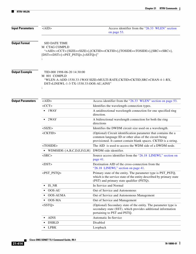
Chapter 21 RTRV CommandsRTRV-WLEN
Input Parameters
Output Format SID DATE TIMEM CTAG COMPLD “<AID>:<CCT>:[SIZE=<SIZE>],[CKTID=<CKTID>],[TOSIDE=<TOSIDE>],[SRC=<SRC>],[DST=<DST>]:<PST_PSTQ>,[<SSTQ>]”;
Output Example TID-000 1998-06-20 14:30:00M 001 COMPLD “WLEN-A-ADD-1530.33:1WAY:SIZE=MULTI-RATE,CKTID=CKTID,SRC=CHAN-4-1-RX, DST=LINEWL-1-3-TX-1530.33:OOS-AU,AINS”;
Output Parameters
<AID> Access identifier from the “26.33 WLEN” section on page 53.
<AID> Access identifier from the “26.33 WLEN” section on page 53.
<CCT> Identifies the wavelength connection types.
• 1WAY A unidirectional wavelength connection for one specified ring direction.
• 2WAY A bidirectional wavelength connection for both the ring directions
<SIZE> Identifies the DWDM circuit size used on a wavelength.
<CKTID> (Optional) Circuit identification parameter that contains the a common language ID or other alias of the circuit being provisioned. It cannot contain blank spaces. CKTID is a string.
<TOSIDE> The AID is used to access the WDM side of a DWDM node.
• WDMSIDE-{A,B,C,D,E,F,G,H} DWDM side identifier.
<SRC> Source access identifier from the “26.18 LINEWL” section on page 41.
<DST> Destination AID of the cross-connection from the “26.18 LINEWL” section on page 41.
<PST_PSTQ> Primary state of the entity. The parameter type is PST_PSTQ, which is the service state of the entity described by primary state (PST) and primary state qualifier (PSTQ).
• IS_NR In Service and Normal
• OOS-AU Out of Service and Autonomous
• OOS-AUMA Out of Service and Autonomous Management
• OOS-MA Out of Service and Management
<SSTQ> (Optional) Secondary state of the entity. The parameter type is secondary state (SST), which provides additional information pertaining to PST and PSTQ.
• AINS Automatic In-Service
• DSBLD Disabled
• LPBK Loopback
21-414Cisco ONS SONET TL1 Command Guide, R9.1
78-18890-01

Chapter 21 RTRV CommandsRTRV-WLEN
• MEA Mismatch of Equipment
• MT Maintenance
• OOG Out of Group
• SWDL Software Download
• UAS Unassigned
• UEQ Unequipped
21-415Cisco ONS SONET TL1 Command Guide, R9.1
78-18890-01

Chapter 21 RTRV CommandsRTRV-WLEN
21-416Cisco ONS SONET TL1 Command Guide, R9.1
78-18890-01