rubber buffers
DESCRIPTION
fdfsdfsdfTRANSCRIPT

Novibra® - product description
Universal mounting for industrial, marine and other mobile installations, i.e.generating sets, combustion engines, compressors and pumps.
As RA, but specifically recommended for installations where a high degree of iso-lation is required.
Effective damping on small 1, 2 and 3 cylinder engines or other installations with excessive movements.
An extremely soft mounting providing a high degree of isolation and shock protection on fans, electric motors, computers etc.
Suitable for the isolation of low speed machines - light fans,instruments and gauging equipment.
Designed to permit high compression under vertical load but in the same timestable in the horizontal direction. Suitable for off road installations for instanceto engine installations and cabin suspension
Vibration isolation on engines, operator cabins and other ancillary, mainly for mobile applications.
ContentsNovibra® – Provides a healthier environmentNovibra® – A safe choiceNovibra® – vibration technology• Vibration causes structure borne noise• Novibra reduce the total cost• The properties of rubber makes it particulary suitable as a spring mount• Rubber as an engineering material• The most important properties for rubber• Spring coefficients• Stresses• Stiffness of a rubber spring• Calculation of antivibration mounting• Some vibration definitions• Calculation of deflections• Calculation of isolation degree• Shock isolation• Unit conversion• General set up• Assistance when choosing antivibration mounting
RA
RAEM
RAB
M
BA
HK/MK
EH
4

Suitable for the suspension of cabins on industrial and agricultural vehicles, liketractors, combine-harvestor, street sweepers, fork-lift trucks, etc.
Dual stiffness mounting for crushers, mills, grinders and similar large, heavyequipment.
A heavy duty mounting for large machines, such as refiners, defibrators, industrial fans, mixers, roll-mills and all types of inertia blocks.Also for supporting floating floors and control rooms.
For vibration-isolation of limited requirements on e.g. printing machines, pillar drills, transformers, lathes.
General workshop mounting with height adjustment, also suitable for punches,presses, etc.
As TF for installation of presses, punches, weaving machines, printing machinesand other heavy high-speed machines.
A simple mounting for office apparatus, sewing machines, electric motors, etc.
For the protection of instruments and apparatus on walls and ceilings.Particularly suitable for installation on board ships.
A shock absorbing mounting for the isolation of shocks on mobile installationse.g. off-road and rail vehicles, cranes and overhead cranes.
For solving bearing problems in vibrating and oscillating constructions.
A supplementary range of cylindrical mountings.
Height adjuster for precise coupling alignment of engine installations and boatbuilding tolerances (for use with RA, RAEM, RAB and M).
UH
SAW
GK
Novibra plate
TF/TFE
U
SE
VT/TK
ANB
VP
Bobbins
HA
Novibra® – Questionnaire
5

Novibra type RA
16
APPLICATION
For the effective isolation of vibration and noise ondifferent machines with rotating movements, like:
• compressors • pumps• combustion engines • industrial and • generators marine gen-sets• converters • fans
Also suitable for use with presses, punches and otherworkshop machines.
FEATURES
RA uses the rubber profile in shear and compression, obtai-ning good vertical flexibility with the advantage of horizon-tal stability. For normal speeds of approx. 1500 rpm, theRA type provides a degree of isolation of 75-85%. For evenbetter isolation, the alternative RAEM or M can be chosen.
Its unique construction and the latest production met-hods make Novibra type RA a high performance moun-ting having a number of advantages:
• Rubber features are utilised effectively combining compression and shear.
• Tight tolerances on dynamic stiffness rate for accurate vibration calculations.
• Wide load rating options, 40-2100 kg.• Corrosion protected to cope with arduous environments
on land or marine applications (Fe/Zn 8C as per ISO 2081).
• Stronger base metal withstands high shock loads without deformation.
• Fitted as standard with a shock-proof device with resili-ent stop, making RA ideal for use on mobile or marineapplications. The RA-mounts can manage occasionalshock loads up to 5 g refered to the weight in hardness B.The mount can withstand shock loads up to 2 g without plastic deformation.
• Clear and durable product marking so that mountingscan be identified even after several years in operation.
• Domed shape cover to protect against oil contamination.
Art.No. Art.No.Hardness A Hardness B Dimensions in mm Weight M-Max(kg)
Type (40° IRH) (60° IRH) D A H K d G (kg) A (40° IRH) B (60° IRH)RA 100/M10 1861700 1861710 79 110 30 130 9 M10 0.330 105 240RA 100/M12 2256120 2256130 79 110 30 130 9 M12 0.330 105 240RA 200/M10 1861740 1861750 94 124 35 150 10 M10 0.470 180 280RA 200/M12 2255720 1860350 94 124 35 150 10 M12 0.470 180 280RA 350/M12 2256370 2256380 101 140–148 38 175 14 M12 0.737 250 450RA 350/M16 1861760 1861770 101 140–148 38 175 14 M16 0.737 250 450RA 500 1861800 1861810 123 158 42 192 14 M16 1.020 450 700RA 800 1861820 1861830 144 182 48 216 14 M16 1.589 750 1300RA 1200 2255360 2255370 161 140 58 170 14 M20 2.188 900 1600RA 1800 2255380 2255390 181 160 66.5 190 14 M20 2.325 1300 2100
RA 100, RA 200, RA 500, RA 800
RA 350
RA 1200, RA 1800

Novibra type RA
17
10
To select correct mounting, following data are needed:1) Load per mounting (kg)2) Interfering frequency (Hz) (Hz = rpm / 60 )Select correct load line in diagram 1 and correct interference line in diagram 3.The load line intersects with required type of mounting.Connect this intersection point verticallydown to the interference line in diagram 3.Here, on the sloping curve, the isolation degree is indicated.For static deflection, see diagram 2.
L
I
1
3
2
21 3 4 5 6 7 8 10
98/3495/26
90/20
85/1680/14
70/10
50/6
0
789
15
20
30
40
50
6070
8090
100
Diagram 3
Interfering frequency (Hz) Natural frequency (Hz) Static deflection (mm)
Degree of isolation (%)/Reduction (dB)
7 8 9 10 12 14 16 18 20
2 500
2 000
1 500
1 000900800700600
500
400
300
200
150
10090807060
50
40
30
Diagram 1
RA 1800 B
RA 1800 A
RA 200 B RA 100 B
RA 800 A
RA 500 A
RA 350 ARA 200 A
RA 100 A
RA 1200 A
RA 1200 BRA 800 B
RA 500 B
RA 350 B
Diagram 2
RA 18
00 B
RA 12
00 B
RA 50
0 B
RA 35
0 B
RA 12
00 A
RA 80
0 A
RA 10
0 B
RA 20
0 A
RA 10
0 A
RA 35
0 A
RA 20
0 B
RA 50
0 A
RA 80
0 B
RA 18
00 A
11 13
10
25
Resonance
Avoid this region
Note: The natural frequencies, degrees of isolation and dB-reductions are based on the measured dynamic characteristics of the mountings.
Load per mounting (kg)

Novibra type RAEM
18
APPLICATION
For the effective isolation of vibration and noise ondifferent machines with rotating movements, like:
• compressors • large milling• AC units machinery• industrial fans • industrial and• generators marine gen sets• combustion engines • refiners• emergency power sets • defibrators
FEATURES
RAEM is a universal mounting for applications demandingmaximum isolation. It is a further development of RA,
where EM stands for ”extra soft”. Suitable for both lightand heavy machines.For normal speeds of approx. 1500 rpm the RAEM typeprovides a degree of isolation of 85-95%, and gives a goodisolation even with low frequency machines.
Its unique construction and the latest production met-hods make Novibra type RAEM a high performancemounting having a number of advantages:
• Rubber features are utilised effectively combining compression and shear.
• Tight tolerances on dynamic stiffness rate for accurate vibration calculations.
• Wide load rating options, 10-3400 kg.• Corrosion protected to cope with arduous environments
on land or marine applications (Fe/Zn 8C as per ISO 2081).
• Stronger base metal withstands high shock loads without deformation.
• Fitted as standard with a shock-proof device with resili-ent stop, making RAEM ideal for use on mobile ormarine applications. The RAEM-mounts can manageoccasional shock loads up to 5 g refered to the weight inhardness B.The mount can withstand shock loads up to 2 g without plastic deformation.
• Clear and durable product marking so that mountingscan be identified even after several years in operation.
• Domed shape cover to protect against oil contamination.
Art.No. Art.No.Hardness AHardness B Dimensions in mm Weight M-Max(kg)
Type (40° IRH) (60° IRH) D A H K d G (kg) A (40° IRH) B (60° IRH)RAEM 40 1861860 1861870 64 88 35.5 110 9 M10 0.255 30 60RAEM 60 2256760 2256770 63 100 35.5 120 11 M12 0.295 60 120RAEM 125 M10 1861720 1861730 84 110 35.5 135 11 M10 0.372 80 180RAEM 125 M12 2256140 2256150 84 110 35.5 135 11 M12 0.372 80 180RAEM 350 M12 2256440 2256450 110 140–148 42 175 14 M12 0.800 200 400RAEM 350 M16 1861780 1861790 110 140–148 42 175 14 M16 0.800 200 400RAEM 800 1861840 1861850 155 182 54 216 14 M16 1.784 450 800RAEM 1500 2255400 2255410 182 146 85 180 14 M20 3.000 900 1700RAEM 2500 2255420 2255430 224 180 105.5 220 17.5 M24 4.620 1700 3400RAEM 1500 Duplex(*) 101105 248 146 115 180 14.5 M20 900
RAEM 60 RAEM 1500, RAEM 2500
RAEM 350RAEM 40, RAEM 125, RAEM 800
(*) No stop device

Novibra type RAEM
19
54 6 7 8 9 10 12 14 16 18 20
3 500
1 500
1 000800
600500400
300250200
150
100
Diagram 1
21 3 4 5 208 10 1576
98/3495/26
90/20
85/1680/1470/1050/6
0
4
5
678
10
15
20
30
40
5060708090
100
Diagram 3
Interfering frequency (Hz) Natural frequency (Hz) Static deflection (mm)
Degree of isolation (%)/Reduction (dB)
RAEM
250
0 B
RAEM
150
0 A
RAEM
150
0 B
RAEM
250
0 A
3 0002 500
2 000
80
605040
30
2025
15
10
Diagram 2
RAEM 40 A
RAEM 125 ARAEM 60 A
RAEM 40 B
RAEM 350 A
RAEM 800 A
RAEM 1500 ARAEM 800 BRAEM 350 B
RAEM 2500 BRAEM 1500 B
RAEM 2500 B
RAEM 125 B
RAEM 60 B
RAEM
800
BRA
EM 8
00 A
RAEM
350
B
RAEM
125
BRA
EM 4
0 ARA
EM 6
0 A
RAEM
40
B
Avoid this region
Resonance
RAEM 350 A
RAEM
60
B
To select correct mounting, following data are needed:1) Load per mounting (kg)2) Interfering frequency (Hz) (Hz = rpm / 60 )Select correct load line in diagram 1 and correct interference line in diagram 3.The load line intersects with required type of mounting.Connect this intersection point verticallydown to the interference line in diagram 3.Here, on the sloping curve, the isolation degree is indicated.For static deflection, see diagram 2.
L
I
1
3
2
70
700
3 30
3
9
25
RAEM 1500 Duplex A
RAEM
125
A
RAEM
150
0 Dup
lex
A
Note: The natural frequencies, degrees of isolation and dB-reductions are based on the measured dynamic characteristics of the mountings.
Load per mounting (kg)
20
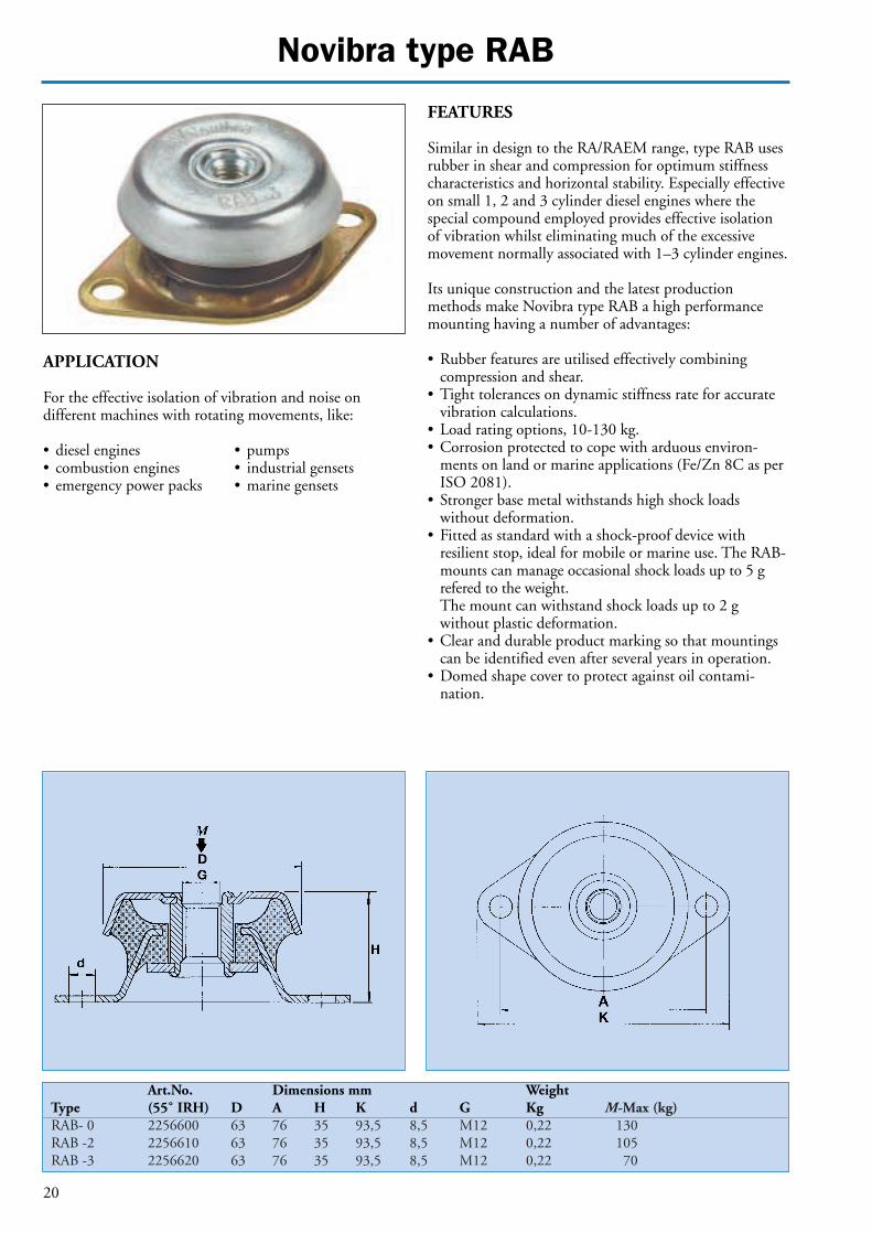
Novibra type RAB
APPLICATION
For the effective isolation of vibration and noise ondifferent machines with rotating movements, like:
• diesel engines • pumps• combustion engines • industrial gensets• emergency power packs • marine gensets
FEATURES
Similar in design to the RA/RAEM range, type RAB usesrubber in shear and compression for optimum stiffnesscharacteristics and horizontal stability. Especially effectiveon small 1, 2 and 3 cylinder diesel engines where the special compound employed provides effective isolationof vibration whilst eliminating much of the excessivemovement normally associated with 1–3 cylinder engines.
Its unique construction and the latest production methods make Novibra type RAB a high performancemounting having a number of advantages:
• Rubber features are utilised effectively combining compression and shear.
• Tight tolerances on dynamic stiffness rate for accuratevibration calculations.
• Load rating options, 10-130 kg.• Corrosion protected to cope with arduous environ-
ments on land or marine applications (Fe/Zn 8C as perISO 2081).
• Stronger base metal withstands high shock loads without deformation.
• Fitted as standard with a shock-proof device with resilient stop, ideal for mobile or marine use. The RAB-mounts can manage occasional shock loads up to 5 grefered to the weight.The mount can withstand shock loads up to 2 g without plastic deformation.
• Clear and durable product marking so that mountingscan be identified even after several years in operation.
• Domed shape cover to protect against oil contami-nation.
Art.No. Dimensions mm WeightType (55˚ IRH) D A H K d G Kg M-Max (kg)RAB- 0 2256600 63 76 35 93,5 8,5 M12 0,22 130RAB -2 2256610 63 76 35 93,5 8,5 M12 0,22 105RAB -3 2256620 63 76 35 93,5 8,5 M12 0,22 70
Novibra type RAB
21
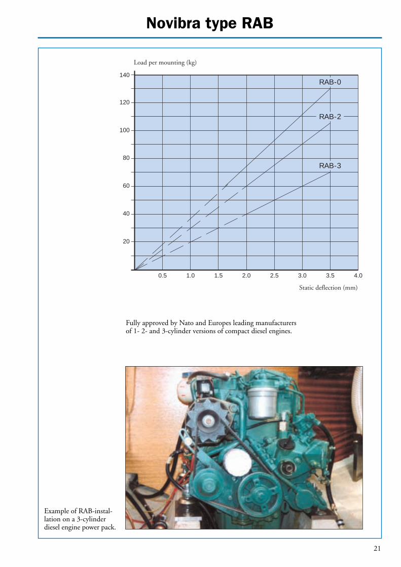
140
120
100
80
60
40
0.5 1.0 1.5 2.0 2.5 3.0 3.5 4.0
20
Static deflection (mm)
RAB-3
RAB-2
RAB-0
Load per mounting (kg)
Fully approved by Nato and Europes leading manufacturersof 1- 2- and 3-cylinder versions of compact diesel engines.
Example of RAB-instal-lation on a 3-cylinderdiesel engine power pack.

Novibra type M
22
APPLICATION
Type M is ideal for applications involving isolation of lowfrequency vibrations in all planes. Also suitable for shockattenuation due to the designed ability to give largedeflections whilst providing passive vibration on electro-nic instruments, measuring equipment, test cells.
Specific fields of application are:
• compressors • electric motors• refrigerators • weighing scales• AC-units • test cell equipment• ventilators • noise control units• fans • pumps• powder handling machinery • food processing• vibratory screens equipment• packaging applications
FEATURES
Novibra type M is specifically designed to give high resili-ence at low loads. Although the mount design allows highdeflection, they are compact in weight and easy to install.
Its unique construction and the latest production met-hods make Novibra type M a high performance antivibra-tion mounting having a number of advantages:
• Tight tolerances on dynamic stiffness rate for accuratevibration calculations.
• Wide load rating options, 3,5–2500 kg.• Corrosion protected to cope with arduous environ-
ments on land or marine applications (Fe/Zn 8C3 asper ISO 2081).
• Clear and durable product marking so that mountingscan be identified even after several years in operation.
When using M mount together with the height adjusterHA it is necessary to use a washer. The diameter of thewasher must be 20% larger than the diameter of theupper plate (D).
Art.No. Art.No.Hardness A Hardness B Dimensions in mm Weight M-Max(kg)
Type (40° IRH) (60° IRH) D E A K H h d G Kg A (40° IRH) B (60° IRH)M 7 2255110 2255120 18 43 50 64 20 7 7 M 6 0,02 3,5 9M 25 1861220 1861230 33 56 66 85 25 11 8 M 8 0,07 20 50M 50 1861240 1861250 45 76 92 114 35 14 10 M 10 0,16 40 80M 100 1861620 1861610 53 96 110 136 40 15 11,5 M 10 0,26 70 150M 200 1861660 1861670 58 101 124 151 45 13 11,5 M 10 0,42 130 220M 400 1861680 1861690 78 120 150 63 18 14,5 M 12 1,06 280 500M 600 1533710 1533720 100 160 200 85 25 14,5 M 16 2,35 380 750M 1500 1533730 1533740 186 250 310 160 43 18 M 24 9,43 1400 2500
M 7, M 25, M 50,M 100, M 200
M 400, M 600, M 1500

Novibra type M
23
Diagram 1 Diagram 225003000
2000
1500
1000
800700600500
400
300
200
150
100
80706050
40
30
20
15
102 3 4 5 6 7 8 9 10 12 14 16 18 20 2 3 4 5 6 7 8 9101214161820 30 40 50
Diagram 32
10
3
45678
15
20
30
4050607080
100
50/670/1080/1485/1690/20
0
95/26
Load per mounting (kg)M25 – M1500
10
8765
4
3
2
1,5
1
9
98/34
Interfering frequency (Hz) Natural frequency (Hz) Static deflection (mm)
Degree of isolation (%) / Reduction (dB)
M25A
M7A
M25B
M7B
M100BM
200A
M100A
M200B
M600B
M400BM
600AM400A
M1500B
M1500A
M15
00B
M60
0B
M15
00A
M40
0B
M20
0B
M10
0BM
200A
M50
BM
7B
M7A
M25
B
M50
A
M25
A
M50A
To select correct mounting, following data are needed:1) Load per mounting (kg)2) Interfering frequency (Hz) (Hz = rpm / 60 )Select correct load line in diagram 1 and correct interference line in diagram 3.The load line intersects with required type of mounting.Connect this intersection point vertically down to the interference line in diagram 3.Here, on the sloping curve, the isolation degree is indicated.For static deflection, see diagram 2.
L
I
1
3
2
M50B
Avoid this region
Resonance
M7 A, M7 B 1 2 2,5 3 4 525
M10
0A
M40
0AM
600A
25
Note: The natural frequencies, degrees of isolation and dB-reductions are based on the measured dynamic characteristics of the mountings.
Load per mounting (kg)M7A, M7B

Novibra type BA
24
APPLICATION
Novibra type BA is equally suitable for isolating vibra-tions from low speed machines and equipment whilst alsoprotecting sensitive and lightweight units from externalshocks and vibrations.
Type BA is very easy to install and ideal for applicationslike:
• light fans and compressors• portable gensets and pumps• computers and electronic units• transit cases• measuring and test instruments• gauging equipment
FEATURES
Novibra type BA utilises bonded rubber in shear to per-mit relatively high deflections to occur, thus providingexcellent isolation of low frequencies. (Type BA 20/2 is ahalfsection suitable for very light loads).
On revolving equipment applications the soft axis shouldbe at right angles to the shaft, whilst in mobile applica-tions the stiff axis should be aligned in the direction oftravel.For transit case applications the mountings need to bearranged so that the horizontal stiffness is the same in alldirections.
Art.No. Art.No.Hardness A Hardness B Dimensions in mm Weight M-Max(kg)
Type (40° IRH) (60° IRH) B L H A d t (kg) A (40° IRH) B (60° IRH)BA 20/2 67868 67876 20 90 58 62 8 4 0.09 12 27BA 20 2255230 2255240 20 90 50 10 4 0.16 20 35BA 50 2255250 2255260 50 90 50 12 4 0.42 60 110BA 100 2255270 2255280 100 90 50 15 4 0.83 130 250
BA 20–BA 100BA 20/2
Rubber inshear (soft)
Rubber incompression
Rubber inshear (soft)

25
Novibra type BA
Diagram 3
Resonance
Avoid this region
76 8 9 10 12 14 16 18 20
300
250
150
100
9080706050
40
30
20
15
1098765
4
321 3 4 5 6 7 8 9 10
98/34
95/26
90/2085/1680/1470/10
50/6
0
6789
10
20
30
40
50
60708090
100
Interfering frequency (Hz) Natural frequency (Hz) Static deflection (mm)
Degree of isolation (%)/Reduction (dB)
To select correct mounting, following data are needed:1) Load per mounting (kg)2) Interfering frequency (Hz) (Hz = rpm / 60 )Select correct load line in diagram 1 and correct interference line in diagram 3.The load line intersects with required type of mounting.Connect this intersection point verticallydown to the interference line in diagram 3.Here, on the sloping curve, the isolation degree is indicated.For static deflection, see diagram 2.
L
I
1
3
2
Diagram 1 Diagram 2
5
5
BA 100 B
BA 10
0 B
BA 50 B
BA 100 A
BA 50 A
BA 20 BBA 20/2 BBA 20 A
BA 20/2 ABA
100
ABA
50 B
BA 50
A
BA 20
BBA
20/2
BBA
20 A
BA20/
2 A
Note: The natural frequencies, degrees of isolation and dB-reductions are based on the measured dynamic characteristics of the mountings.
Load per mounting (kg)

26
Novibra type HK/MK
FEATURES
Novibra Antivibration mounting type HK/MK is desig-ned to permit high compression under vertical load but isat the same time stable in the horizontal direction.The conical shape makes the rubber work in both shearand compression stresses in a favourable way.
APPLICATION
Novibra type HK/MK has a special resilient nature andimpact resistance which make it suitable for isolatingcombustion engines in mobile applications as in ships,heavy construction vehicles and tractors. HK is also suita-ble for isolation of cabs on the same type of machines.
The MK is supplied with shock absorbing washers, whilstwashers for the HK 150 and HK 600 should be orderedseparately.
Type Art.No. OD (mm) ID (mm) Thickness (mm)Washer upper HK 150 2230390 75 16H11 4Washer lower HK 150 2230400 55 16H11 5Washer upper HK 600 2230560 55 20H11 5Washer lower HK 600 2230570 110 20H11 5
Dimensions in mm Weight M-MaxType Art.No. A K F H h D d d1 t (kg) (kg)
MK 80 A 2256030 80 107 70 51 16.5 62 12 11 2.5 0.37 100MK 80 B 2256040 80 107 70 51 16.5 62 12 11 2.5 0.37 175MK 80 C 2256050 80 107 70 51 16.5 62 12 11 2.5 0.37 285
Dimensions in mm Weight M-Max Type Art.No. A1 B1 A2 B2 K F D d R t H h (kg) (kg)
HK 150 A 2256920 65 80 69.4 82.7 92 107 74 16H11 5.5 4 64 19 0.65 225HK 150 B 2256930 65 80 69.4 82.7 92 107 74 16H11 5.5 4 64 19 0.65 545HK 600 A 2256940 92 112 98 98 121 140 103 20H11 5.5 4 85 20 1.0 940HK 600 B 2256950 92 112 98 98 121 140 103 20H11 5.5 4 85 20 1.0 1700
HK MK
M

27
Novibra type HK/MK
Diagram 1
76 8 9 10 11 12 13 14 15 20
1 000
600
500
400
300
250
200180160
1 5 10
98/3495/26
90/20
85/1680/1470/10
50/6
6
10
15
20
30
40
50
25
100
Diagram 3
Interfering frequency (Hz) Natural frequency (Hz) Static deflection (mm)
Degree of isolation (%)/Reduction (dB)
2 000
140120
100
40
Diagram 2
To select correct mounting, following data are needed:1) Load per mounting (kg)2) Interfering frequency (Hz) (Hz = rpm / 60 )Select correct load line in diagram 1 and correct interference line in diagram 3.The load line intersects with required type of mounting.Connect this intersection point verticallydown to the interference line in diagram 3.Here, on the sloping curve, the isolation degree is indicated.For static deflection, see diagram 2.
L
I
1
3
20
Avoid this region
Resonance
HK 600 B
HK 600 A
HK 150 B
MK 80 BHK 150 A
MK 80 A
HK
600
B
HK
600
A
HK
150
BM
K 80
BHK
150
AM
K 80
A
MK 80 C
Note: The natural frequencies, degrees of isolation and dB-reductions are based on the measured dynamic characteristics of the mountings.
Load per mounting (kg)

28
Novibra type EH
APPLICATION
Type EH mountings are designed to achieve effectivevibration isolation on engines, operator cabins and otherancillary units.
Typical applications can be found in the following areas:
• Off-road equipment • Construction equipment• Military vehicles • Agricultural vehicles• Transport machinery • Industrial mobile machinery
Max tightening torque • EH 4850: 40 Nm• EH 6463: 80 Nm• EH 9075: 200 Nm
FEATURES
Type EH is designed mainly for mobile applicationswhere high dynamic and shock forces are encountered.
Dynamic vertical movements in both the directions arerestricted and excellent stability is provided horizontally.
Racking and twisting stress of brackets are accommo-dated while at the same time obtaining vibration isolationand shock absorption.
The function of EH includes features as:
• Dynamic efficiency in all directions• Attenuation of structural borne noise• Accommodation of misalignment and distortion• Simple design – easy to install• Fail-safe installation• Wide load range, 80 to 450 kg
Dimensions in mmType C E REH 4850 31.0 15.0 1.5EH 6463 39.0 22.0 2.3EH 9075 56.5 28.0 3.0
Machine inoperation
Machine inoperation
Exemple of installation
Art.No. Art.No. Dimensions in mm Max load (kg)Type Hardness A Hardness B d D D1 H H1 H2 H3 H4 A B
EH 4850 1860570 1860560 13.0 50 32 50 20 10 20 20 60 120EH 6463 1860550 1860540 17.0 64 40 62 23 14 25 23 100 190EH 9075 1860530 1860520 23.0 89 58 73 25 19 29 25 260 420
Table of measures for installation
Exemple of installation

29
Novibra type EH
1110 12 13 14 15 16 17 18 19 20 21 22 23 24 25
500450400
350
300
250
200180160
140
120
1009080
70
0.80.5 1 31.5 2 2.5
95/26
90/2085/1680/14
70/10
50/6
0
15
20
10
25
30
40
50
60
70
8090
100
EH 9
075
B
EH 6
463
B &
EH 9
075
A
60
50
40
30
20
EH 6
463
A
EH 4
850
A
Avoid this region
Resonance
EH 4
850
B
EH 9075 B
EH 6463 B
EH 4850 BEH 6463 A
EH 4850 A
EH 9075 A
To select correct mounting, following data are needed:1) Load per mounting (kg)2) Interfering frequency (Hz) (Hz = rpm / 60 )Select correct load line in diagram 1 and correct interference line in diagram 3.The load line intersects with required type of mounting.Connect this intersection point verticallydown to the interference line in diagram 3.Here, on the sloping curve, the isolation degree is indicated.For static deflection, see diagram 2.
L
I
1
3
2
Diagram 1 Diagram 2
Diagram 3
Interfering frequency (Hz)
Degree of isolation (%)/Reduction (dB)
Static deflection (mm)Natural frequency (Hz)
Note: The natural frequencies, degrees of isolation and dB-reductions are based on the measured dynamic characteristics of the mountings.
Load per mounting (kg)
30
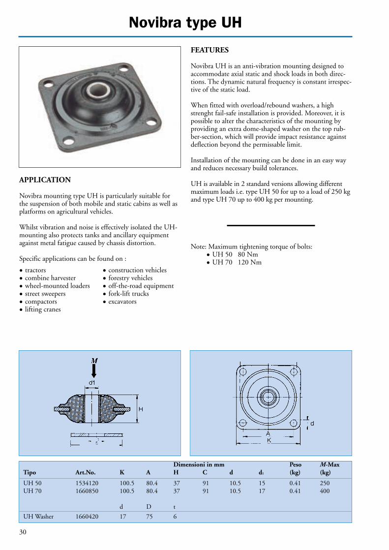
Novibra type UH
Dimensioni in mm Peso M-MaxTipo Art.No. K A H C d d1 (kg) (kg)
UH 50 1534120 100.5 80.4 37 91 10.5 15 0.41 250UH 70 1660850 100.5 80.4 37 91 10.5 17 0.41 400
d D t
UH Washer 1660420 17 75 6
APPLICATION
Novibra mounting type UH is particularly suitable forthe suspension of both mobile and static cabins as well asplatforms on agricultural vehicles.
Whilst vibration and noise is effectively isolated the UH-mounting also protects tanks and ancillary equipmentagainst metal fatigue caused by chassis distortion.
Specific applications can be found on :
• tractors • construction vehicles • combine harvester • forestry vehicles• wheel-mounted loaders • off-the-road equipment • street sweepers • fork-lift trucks• compactors • excavators• lifting cranes
FEATURES
Novibra UH is an anti-vibration mounting designed toaccommodate axial static and shock loads in both direc-tions. The dynamic natural frequency is constant irrespec-tive of the static load.
When fitted with overload/rebound washers, a highstrenght fail-safe installation is provided. Moreover, it ispossible to alter the characteristics of the mounting byproviding an extra dome-shaped washer on the top rub-ber-section, which will provide impact resistance againstdeflection beyond the permissable limit.
Installation of the mounting can be done in an easy wayand reduces necessary build tolerances.
UH is available in 2 standard versions allowing differentmaximum loads i.e. type UH 50 for up to a load of 250 kgand type UH 70 up to 400 kg per mounting.
Note: Maximum tightening torque of bolts:• UH 50 80 Nm • UH 70 120 Nm

31
Novibra type UH
Diagram 1
UH 70
UH 50
To select correct mounting, following data are needed:1) Load per mounting (kg)2) Interfering frequency (Hz) (Hz = rpm / 60 )Select correct load line in diagram 1 and correct interference line in diagram 3.The load line intersects with required type of mounting.Connect this intersection point verticallydown to the interference line in diagram 3.Here, on the sloping curve, the isolation degree is indicated.For static deflection, see diagram 2.
Resonance
Avoid this region
98/34
95/26
90/20
85/1680/14
70/10
50/6
0
Interfering frequency (Hz)
Degree of isolation (%)/Reduction (dB)
7
10
20
30
40
50
60
708090
100
1 2 3 4 5 6 7 8 10 12Static deflection (mm)Natural frequency (Hz)
4000
30002500
2000
1500
1000900800700600
500
400
300
200
150
1009080706050
7 8 9 10 11 12 13 14 15 16 17
Diagram 2
Diagram 3
UH 70
UH 50
L
I
Note: The natural frequencies, degrees of isolation and dB-reductions are based on the measured dynamic characteristics of the mountings.
Load per mounting (kg)

32
Novibra type SAW
Art.No. Art.No.Hardness A Hardness B Dimensions in mm Weight M-Max(kg)
Type (40° IRH) (60° IRH) A K H d t (kg) A (40° IRH) B (60° IRH)SAW 125 2255130 2255140 118 148 52 13.5 5 2.6 2250 4500SAW 150 2255150 2255160 136 166 63 13.5 6 4.1 3750 7500SAW 200 814467 814475 184 220 82 17 8 9.2 6000 12000SAW 300 814483 814491 270 310 120 22 10 27.0 15000 30000
APPLICATION
Novibra elements type SAW are heavy duty mountingsfor high vertical static and shock loads in compression,whilst at the same time providing high isolation values inthe horizontal shear direction.
Typical fields of application are:
• crushers • vibratory rollers• edge runners • screens• mills • other very heavy • grinders machines and • hoppers and feeders equipment
FEATURES
Novibra type SAW mountings consists of a cylindricalshaped rubber section with integrally bonded interleafmetal plates which is bonded to two square heavy dutyouter metal fixing plates. It has been designed for largecompressive thrust forces with minimum deformation,whilst providing low shear stiffness rates.The combination of a stable low installation height, highcompressive strength and low shear stiffness makesNovibra type SAW a versatile high performance antivibra-tion mounting. Installation is easy due to only 4 clearanceholes in each fixing plate.
By connecting 2 SAW-elements in series i.e. one on top ofanother, an increased isolation efficiency is achieved inboth shear and compression planes to isolate very low fre-quencies. Where large deflections are required in the verti-cal plane Novibra type SAW mountings can be mountedat a calculated angle configuration to provide the opti-mum spring rate between shear and compression stiffness.
Shear loads only. See separate dia-gram for shearload.

33
Novibra type SAW
To select correct mounting, following data are needed:1) Load per mounting (kg)2) Interfering frequency (Hz) (Hz = rpm / 60 )Select correct load line in diagram 1 and correct interference line in diagram 3.The load line intersects with required type of mounting (both vertical and lateralvibration plane).Connect this intersection point verticallydown to the interference line in diagram 3.Here, on the sloping curve, the isolation degree is indicated.For static deflection, see diagram 2.
L
I
1
3
2
Diagram 3
Resonance
Avoid this region
98/3495/26
90/2085/1680/1470/1050/60
Interfering frequency (Hz)
Degree of isolation (%)/Reduction (dB)
1
2
3
456
8
10
15
20
30405060
80100
1 2 3 4 5 6 7 8 9 10Static deflection (mm)
Diagram 2
SAW
300
B
SAW
125
B
SAW
200
A
SAW
150
A
SAW
125
A
SAW
200
B
SAW
150
B
SAW
300
A
Natural frequency (Hz)
35000
30000
20000
15000
100009000800070006000
5000
4000
3000
2000
1500
1000900800
0.7 0.8 0.9 1 1.5 2 3 4 5 6 7 8 9 10 12 14 16 18 20
SAW 300 B
SAW 200 B
SAW 300 A
SAW 150 B
SAW 125 B
SAW 150 A
SAW 200 A
SAW 125 A
SAW 300 B
SAW 200 B
SAW 300 A
SAW 150 B
SAW 125 B
SAW 200 A
SAW 150 A
SAW 125 A
Diagram 1
Note: The natural frequencies, degrees of isolation and dB-reductions are based on the measured dynamic characteristics of the mountings.
Load per mounting (kg)
Horizontal vibrationVertical load
Vertical vibrationVertical load

34
Novibra type SAW = Shear loads
To select correct mounting, following data are needed:1) Load per mounting (kg)2) Interfering frequency (Hz) (Hz = rpm / 60 )Select correct load line in diagram 1 and correct interference line in diagram 3.The load line intersects with required type of mounting (both vertical and lateralvibration plane).Connect this intersection point verticallydown to the interference line in diagram 3.Here, on the sloping curve, the isolation degree is indicated.For static deflection, see diagram 2.
L
I
1
3
2
Diagram 3
Resonance
Avoid this region
98/34
95/26
90/2085/1680/1470/1050/60
Interfering frequency (Hz)
Degree of isolation (%)/Reduction (dB)
1
2
3
456
8
10
20
30
405060
80100
1 2 3 4 5 678 10 15 20 30 40 50Static deflection (mm)
Diagram 2
SA
W 3
00 B
SA
W 1
25 B
SA
W 2
00 A
SA
W 1
50 A
SA
W 1
25 A
SA
W 2
00 B
SA
W 1
50 B
SA
W 3
00 A
Natural frequency (Hz)
4000
30002500
2000
1500
1000900800700600
500
400
300
200
150
1009080706050
2 2.5 3 3.5 4 5 6 7 8 9 10
SAW 300 B
Diagram 1
SAW 200 BSAW 150 BSAW 125 B
SAW 300 A
SAW 200 A
SAW 150 ASAW 125 A
Note: The natural frequencies, degrees of isolation and dB-reductions are based on the measured dynamic characteristics of the mountings.
Load per mounting (kg)
This page refers to shear load characteristics only!
F max (kg) Hardness A Hardness B
SAW 125 240 570SAW 150 330 850SAW 200 600 1200SAW 300 1575 3150
F
F
F
F

35
Novibra type GK
Dimensions in mmType Art.No. L B H Weight (kg) M-Max(kg)
GK 0 A 1534080 195 175 150 5.2 1800GK 0 B 1861630 195 175 150 5.7 3800GK 1 A 67959 400 175 150 10.7 4000GK 1 B 67967 400 175 150 11.8 8000
APPLICATION
Novibra mounting type GK is specifically meant for isolation of heavy machinery with low interfering frequencies. It is widely used under concrete foundationssupporting heavy machinery.
The long narrow section makes type GK also suitable forcomposite installations on common structural framework.
Typical fields of application are:
• rolling mills • paper mills• mixers • converters• gear wheels • sound encloseres• industrial fans • floating structures
FEATURES
Type GK is a heavy duty mounting with excellent flexiblecharacteristics in both vertical and lateral planes.Deflection up to 30 mm can be obtained which makesNovibra type GK suitable for installations with low disturbing frequencies.
Installation is simple with no need for traditional meansof attachment to machinery or support structure.
SHEAR LOADStatic spring rate

36
Novibra type GK
M M
To select correct mounting, following data are needed:1) Load per mounting (kg)2) Interfering frequency (Hz) (Hz = rpm / 60 )Select correct load line in diagram 1 and correct interference line in diagram 3.The load line intersects with required type of mounting.Connect this intersection point verticallydown to the interference line in diagram 3.Here, on the sloping curve, the isolation degree is indicated.For static deflection, see diagram 2.
L
I
1
3
2
Diagram 1 Diagram 2
Diagram 3
GK 1 B
GK 1 B
GK 0 B
GK 0 B G
K 1 A
GK 1 A
GK 0 A
GK 0 A
100009000
8000
7000
6000
5000
4000
3000
2500
2000
1500
1250
1000900
800
700
600
500
98/34
95/26
90/2085/1680/1470/1050/60
Interfering frequency (Hz)
Degree of isolation (%)/Reduction (dB)
1
2
3
45678
10
15
20
304050607080
100
5 6 7 8 9 10 12 14 16 18 20 25 30 40Static deflection (mm)Natural frequency (Hz)
1 2 3 4 5 6 7 8 9 10
GK
1 B
GK
1 A
GK
0 B
GK
0 A
Resonance
Avoid this region
Note: The natural frequencies, degrees of isolation and dB-reductions are based on the measured dynamic characteristics of the mountings.
Load per mounting (kg)
Horizontal vibrationVertical load
Vertical vibrationVertical load
37
Novibra Anti-vibration Plate
Dimensions in mm Weight M-max loadType Art.No. LxB H (kg) kg/cm2
Single plate 70136 500x600 4.5 1.210 5Double plate 70151 500x600 8 1.815 5
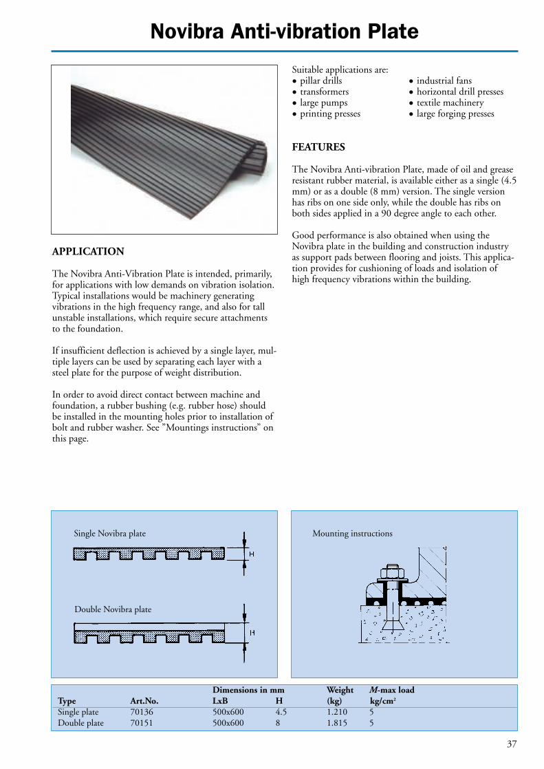
APPLICATION
The Novibra Anti-Vibration Plate is intended, primarily,for applications with low demands on vibration isolation.Typical installations would be machinery generatingvibrations in the high frequency range, and also for tallunstable installations, which require secure attachmentsto the foundation.
If insufficient deflection is achieved by a single layer, mul-tiple layers can be used by separating each layer with asteel plate for the purpose of weight distribution.
In order to avoid direct contact between machine andfoundation, a rubber bushing (e.g. rubber hose) shouldbe installed in the mounting holes prior to installation ofbolt and rubber washer. See ”Mountings instructions” onthis page.
Suitable applications are:• pillar drills • industrial fans• transformers • horizontal drill presses• large pumps • textile machinery • printing presses • large forging presses
FEATURES
The Novibra Anti-vibration Plate, made of oil and greaseresistant rubber material, is available either as a single (4.5mm) or as a double (8 mm) version. The single versionhas ribs on one side only, while the double has ribs onboth sides applied in a 90 degree angle to each other.
Good performance is also obtained when using theNovibra plate in the building and construction industryas support pads between flooring and joists. This applica-tion provides for cushioning of loads and isolation ofhigh frequency vibrations within the building.
Single Novibra plate Mounting instructions
Double Novibra plate

38
Novibra Anti-vibration Plate
5 0.5
4 0.4
3 0.3
2 0.2
1 0.1
0 00 0.5 1.0 1.5 2.0 2.5 mm
Static deflection
1-layer 2-layer 3-layerkp/cm2 MPa
Single Novibra plate
5 0.5
4 0.4
3 0.3
2 0.2
1 0.1
0 00 1.0 2.0 3.0 4.0 5.0 mm
Static deflection
1-layer 2-layer 3-layerkp/cm2 MPa
Double Novibra plate
Load

39
Novibra type TF
Dimensions in mm Overall Thread Weight Max loadType Art.No. D H min H max bolt length G (kg) (kg)TF 250 1860740 69 23 1) 100 M 12 0.355 250TF 600 1860780 81 25 1) 100 M 12 0.486 600TF 1200 1860790 108 29 1) 100 M 16 0.990 1200TF 3000 1860800 151 35 1) 120 M 20 2.223 3000TF 4000 1860810 170 39 1) 120 M 20 2.925 4000TF 6000 1860820 205 44 1) 150 M 24 4.813 6000
APPLICATION
Novibra type TF with level adjuster is a modern machinemounting suitable for a wide range of free standing work-shop machines, like:• lathes• milling machines• grinding machines• multiple operation machinery• presses• plate shears• nibbling machines• punches and cutters• carpentry machines • plastic moulding machinery
FEATURES
The TF mounting can be installed in a matter of minutesby following the instructions provided. There is no needto fix the machines to the floor since the rubber sole ofthe mounting keeps the machine in place. Whenevernecessary, a machine can easily be re-positioned. The levelcan be adjusted with load applied.
The rubber element of the TF mounting is oil and che-mical resistant whilst all metal parts are zincplated andchromated for protection against corrosion.
Models TF 250, TF 600 and TF 1200, also available inS/S (ISO 2604/11, BS 3605:1)
1) Levelling of the bolt up to its total lenght.

40
Novibra type TF
Mounting TFE is a simpler version of type TF withoutlevel adjuster. It is used for machines which do not requi-re height adjustment or where such function is alreadyprovided, e.g. by an adjusting screw in the machine.
Both models also available in S/S (ISO 2604/11,BS 3605:1 )
Type of machine General work- Presses and punchesshop machines Number of strokes per minute
Type of mounting Max load (kg) 1– 125 126– 175 176– 225226– 275
TF 250 250 25– 125 20– 100 15– 85 10– 60TF 600 251– 600 126– 300 101– 240 86– 200 61– 150TF 1200 601– 1200 301– 600 241– 480 201– 400 151– 300TF 3000 1201– 3000 601– 2400 481– 1600 401– 1000 301– 750TF 4000 3001– 4000 2401– 3200 1601– 2100 1001– 1300 751– 1000
Loading range per mounting (kg)
Mounting instructions
Novibra type TFE
Dimensions in mm Weight Max loadType Art.No. D H (kg) (kg)TFE 601 1861050 80 25 0.375 800TFE 1201 1861060 109 29 0.925 1600

41
Novibra type U
Art.No. Art.No.Hardness A Hardness B Dimensions in mm Weight M-Max(kg)
Type (40° IRH) (60° IRH) B L H h G (kg) A (40° IRH) B (60° IRH)U 100 67363 67371 50 100 42 12 M12 0.650 200 400U 130 67421 67439 70 130 54 12 M12 1.318 400 800
APPLICATION
Type U provides for a stable machine installation and istherefore particulary suitable for the vibration isolation ofheavier machinery with relatively high interfering frequ-encies.
Typical applications can be found on :
• presses • church bells• punches • transformers• weaving machines • printing machinery• carpentry machines • other heavy high speed
machines
FEATURES
Novibra type U is a robust element consisting of 2 solidU-shaped steel parts securely bonded with rubber. Toachieve higher resilience two holes in the rubber havebeen provided under the innershanks. The upper steelplate is to be mounted under the machine foot or base-plate by means of a bolt whereas the bottom plate shouldbe secured to the floor by e.g. an expansion bolt. For certain applications a dowel pin may be adequate.
U 100 Load per mounting (kg)
U 130Load per mounting (kg)
500
400
300
200
100
01.0 2.0 3.0 4.0 5.0 mm
Hardness BMax 400 kg
Hardness AMax 200 kg
1000
800
600
400
200
01.0 2.0 3.0 4.0 5.0 mm
Hardness BMax 800 kg
Hardness AMax 400 kg

Novibra type SE
42
Art.No. Dimensions in mm Weight M-Max (kg)Hardness R
Type (50° IRH) D D1 d H t (kg) R (50° IRH)
SE 75 1661010 55 18 8 15 3 0.069 150SE 250 1861110 75 25 10 17 4 0.172 400SE 750 1861120 115 40 14 24 4 0.456 1100
APPLICATION
Novibra type SE is most suitable for the isolation of highfrequency disturbances and also provides reduction ofstructure borne noise.
Specific applications are:• office equipment• textile machinery• domestic appliances• electric motors• weighing equipment
FEATURES
The SE-mounting consists of an annular rubber section,securely bonded to a single steel support plate. A clearan-ce hole is provided which can either be left plain or tap-ped to suit the application.
Since the rubber component is in direct contact with thesurface, friction is sufficient to prevent the equipmentfrom ”travelling”.
1000
800
600
400
200
1 2 3 4 5 Static deflection (mm)
Load per mounting (Kg)
SE 750
SE 250
SE 75

45
Novibra shockbuffer type ANB
Dimensions in mm Weight F-MaxType Art.No. K A D d H t (kg) (N)ANB 50 2255290 70 50 50 7 43 3 0.2 8000ANB 75 2255300 100 75 75 9 63 3 0.5 20000ANB 100 2255310 130 100 100 11 84 4 1.2 41000ANB 200 68569 185 150 150 13.5 126 6 3.9 90000ANB 200 68577 240 200 200 13.5 168 8 9.1 180000
APPLICATIONSThe Novibra shockbuffer type ANB is used to effectivelydamp movements of machines or machine componentswhich need to be slowed down or stopped.
Typical field applications would be:• wagons • cabinets• traverse cranes • forestry vehicles• lifting cranes • off-road material • working beams handling equipment• falling goods
Through the excellent resilience of the rubber a highdegree of energy absorption can be achieved. The rubberis stiffer for rapid dynamic processes than for slow staticapplications. With the same deformation this means thatmore energy is absorbed in fast processes than in slowones. Diagram 1 shows the impact of the energy factor.
FEATURES
Novibra buffer type ANB consists of a cylindrical rubberbody bonded to a square baseplate of steel. Each corner ofthe baseplate has a fixing hole.Special high-hysteresis rubber compound is used to ensu-re as much energy absorption as possible so that the volu-me of the rubber is used at an optimum efficiency.It permits that for new machine developments simplerdesigns and lighter calculated forces can be consideredwhich means lower costs.
Fig 1. Traverse crane with shock buffer ANB.
Fig 2. Traverse crane with 2 ANB buffers connected in series.

Novibra shockbuffer type ANB
46
For calculation purposes the following equations canbe used:
E = m·v2 (1)2
E = F · s (2)F = m · a (3)s = a·t2 (4)
2v = a · t (5)v = 2 · a · s (6)v = 2 · g · h (7) applicable in free fall
Equation (4)- (7) at start velocity = 0
E = energy in Nmm = mass in kgv = velocity in m/sF = force in Ns = distance in ma = acceleration in m/s2
t = time in sg = acceleration due to gravity 9.81 m/s2
h = height in md = spring travel in m
Force Force Force
Energy Energy Energy
Diagram 1 Diagram 2 Diagram 3

Novibra shockbuffer type ANB
47
CALCULATION EXAMPLES
The figures in parenthesis refer to the equations.
EXAMPLE 1: FREE FALL CALCULATION1850 kg weight is to be dropped 1.83 metres onto 4 ANBbuffers. What size ANB should be used? What force will betransmitted to the floor?
Energy E = F · S (2) = 1.83 · 1850 · 9.81 = 33212 NM
Velocity at impact (shock velocity) V =2 · g · h (7)= 2 · 9.81 · 1.83 = 6 m/s.
REFER TO ENERGY FACTOR GRAPHIf 50% deformation is allowed, the energy factor at 6 m/sis 0.4.Then dynamic energy 33212 Nm corresponds to 33212 ·0.4 = 13285 Nm static energy and for 4 buffers the staticenergy per buffer is 3320 Nm.
REFER TO FORCE-ENERGY DIAGRAMSelect ANB 200 which can each absorb up to 4300 Nmat 80 mm compression (which is 50% of static height) orwill compress 76 mm at 3320 Nm.
Force at impact surface = force at 76 mm deflection / 0.4 = 150 / 0.4 =375 kN per buffer= 1500 kN for 4 buffers
Hence if 1850 kg is dropped 1.83 metres onto 4 x ANB 200buffers they will each compress 76 mm and the total force onthe floor will be 1500 kN.
EXAMPLE 2A: CRANE BUFFER CALCULATIONA crane weighs 2000 kg and travels at 1.6 m/s. What size ANBbuffers should be used to stop it and what will the final force be?
The dynamic or kinetic energy E =1 = m · v2 = 2000 · 1.62
= 2560 Nm (1)2 2
REFER TO ENERGY FACTOR GRAPHAssuming a 50% deformation, the energy factor = 0.75 at1.6 m/s.Hence the equivalent static energy is 2560 · 0.75 = 1920 Nm.Then for 2 buffers the static energy is 960 Nm per buffer.
REFER TO FORCE-ENERGY DIAGRAMANB 150 buffers can be chosen with a deflection at 960Nm of 49 mm, which is only 41% of a free height of 120mm, whereas 50% had been assumed. With the energyfactor reduced to 0.72 (for 41% deflection at 1.6 m/s) thestatic energy is:
2560/2 x 0.72 = 922 Nm
REFER TO FORCE-ENERGY DIAGRAM FOR ANB 150At 922 Nm static energy, the deflection is 48.5 mm (closeto 49 mm).Then the static force at 48.5 mm deflection is about 51 kN.Therefore the dynamic load (Force at impact) = 51 / 0.72 = 71 kN.
Hence 2 x ANB 150 buffers will deflect 48.5 mm and transmit aforce of 71 kN or 7240 kg each, i.e. the structure must withstand14.6 tons.
EXAMPLE 2B: CRANE BUFFER CALCULATIONHow can the dynamic force calculated in example 2a bereduced, and by how much?
The force will be reduced and the deflection will be incre-ased if ANB 150 buffers are connected in series (i.e. 4buffers instead of 2) as illustrated by fig. 2.Then, assuming 30% deformation the energy factor at1.6 m/s = 0.68.Hence the equivalent static energy is 2560 · 0.68 = 1740 Nmand for 4 buffers the static energy is 435 Nm per buffer.
The force-Energy diagram shows that at 435 Nm, bufferANB 150 deforms 35 mm. This corresponds to 29.2% ofa free height of 120 mm which is close to assumed value30%.
Then the static force at 35 mm deformation is 26 kN andthe dynamic load at impact will be:
26 / 0.68 = 38 kN
Hence 4 x ANB 150 buffers connected 2 + 2 will give a totaldeflection of 70 mm with a final force per double arrangement of38 kN or 3870 kg, i.e. the structure must withstand 7.7 tons.
10
8
6
4
2
00 0.2 0.4 0.6 0.8 1.0
Energy factor
Shock velocity m/s
Diagram 4
50 % deformation of rubber
30 %
15 %

Novibra sleeves type VP
48
Designation Dimensions in mm Torque Bending Axial Radial Aprox.load load weight
Type d D L l Max Max Spring Max Max Spring Max Spring Max Spring (kg)Mv b const. Mb a const. Fa const. Fr const.Nm/ degr. Nm/degr. Nm degr. Nm/degr. N N/mm N N/mm degr.
VP 10/2525 10 25 25 20 5.0 15 0.3 6.0 8 0.7 750 170 2300 2000 0.035VP 10/2540 10 25 40 35 6.0 15 0.4 38.0 8 4.8 1500 380 3800 2350 0.057VP 15/3530 15 35 30 25 9.0 15 0.6 12.0 8 1.5 1500 220 3500 3000 0.076VP 15/3550 15 35 50 45 15.0 15 1.0 120.0 8 15.0 2500 520 6000 6500 0.120VP 20/4540 20 45 40 35 24.0 15 1.6 45.0 8 5.6 2600 330 6800 4000 0.160VP 20/4575 20 45 75 70 48.0 15 3.2 365.0 8 46.0 5500 820 13500 8000 0.315VP 25/5045 25 50 45 40 46.0 14 3.3 96.0 8 12.0 3800 450 9000 4500 0.211VP 25/5085 25 50 85 80 69.0 14 4.9 730.0 8 92.0 7500 960 18000 10500 0.416VP 30/6055 30 60 55 45 78.0 14 5.6 135.0 8 17.0 5100 530 12000 5000 0.335VP 30/60100 30 60 100 90 135.0 14 9.7 1200.0 8 150.0 10500 1150 25000 20000 0.630VP 35/6560 35 65 60 50 93.0 12 7.7 180.0 6 23.0 6600 720 16000 8500 0.434VP 35/65110 35 65 110 100 200.0 11 17.0 1560.0 6 260.0 13000 1550 31500 29400 0.810VP 40/7065 40 70 65 55 138.0 12 11.5 290.0 7 41.0 8300 870 20500 17000 0.555VP 40/70120 40 70 120 110 240.0 11 22.0 2520.0 6 420.0 18000 1750 40000 37750 1.090VP 45/7570 45 75 70 60 240.0 12 20.0 320.0 7 45.0 10000 1100 24000 20000 0.673VP 45/75130 45 75 130 120 340.0 10 34.0 5040.0 6 840.0 20000 2150 40000 42350 1.280VP 50/8075 50 80 75 65 275.0 11 25.0 700.0 7 100.0 12000 1350 28500 30000 0.767VP 50/80140 50 80 140 130 450.0 10 45.0 5160.0 6 860.0 23500 2650 49000 43700 1.484
APPLICATION
Novibra type VP sleeves are used to solve bearing problems in vibrating and oscillating constructions.
Suitable applications are linkage systems in:
• Cars• Railway carriages• Tractors• Trucks• Agricultural machinery• Bulldozers• Vibratory screens
FEATURES
Novibra type VP consists of two concentric sleeves withrubber securely bonded between them. Designed to takeup torsional movements and axial and radial loads. Therubber is prestressed to give maximum dynamic strengthand durability.
The bonded rubber takes up the full movement. Lubrica-tion or other bearing maintenance is not required. Thesleeves also have excellent sound and vibration isolationcapacity, which makes structures fitted with Novibra typeVP sleeves both silent and vibrationfree.
Tolerances
d 10-25±0,130-50±0,2
D +0,25+0,05 with chamfer at one end
l ±0,5L ±0,25

Novibra Bobbins
49
APPLICATIONS AND FEATURES
A supplementary range of cylindrical mountings for a wide range of applications. Theycan be loaded either in compression or shear taking into consideration individualdemands for actual applications.
Made of natural rubber in hardness A (40-45 ° IRH) or hardness B (55-60 ° IRH).
Compression load Shear load
Type A Type B Type C
Type D Type KD Type E

Novibra Bobbins
50
Hardness BType D/H GxL Art.No. Compression load Shear load
Hardn. B kcomp Fmax kshear Fmax(N/mm) (N) (N/mm) (N)
A 10/10 M 4x10 1255720 53 77 10 31A 15/15 M 4x13 1255740 73 170 13 69A 20/15 M 6x15 1255770 145 327 25 123A 20/20 M 6x15 1255300 96 303 18 123A 20/25 M 6x15 1255780 72 292 14 123A 25/10 M 6x18 1255790 574 755 64 192A 25/15 M 6x18 1255800 247 556 38 192A 25/20 M 6x18 1255810 157 495 27 192A 25/25 M 6x18 1255310 116 471 21 192A 25/30 M 6x18 1255820 93 458 17 192A 30/15 M 8x20 1255830 453 930 61 277A 30/20 M 8x20 1255320 261 771 42 277A 30/30 M 8x20 1255840 143 680 26 277A 40/30 M 8x23 1255330 271 1288 47 493A 40/40 M 8x23 1255850 184 1202 34 493A 50/25 M 10x28 1255860 652 2442 93 770A 50/30 M 10x25 1255870 472 2193 75 770A 50/40 M 10x25 1255340 306 1970 54 770A 50/45 M 10x25 1255880 261 1915 47 770A 50/50 M 10x25 1255350 228 1877 42 770A 75/40 M 12x37 1255360 827 5181 124 1732A 75/50 M 12x37 1255900 579 4670 97 1732A 100/55 M 16x41 1255910 994 8908 155 3079
Hardness BType D/H GxL (S) Art.No. Compression load Shear load
Hardn. B kcomp Fmax kshear Fmax(N/mm) (N) (N/mm) (N)
B 20/15 M 6x15 (6) 1255960 159 298 25 123B 20/20 M 6x15 (6) 1255970 105 275 18 123B 25/25 M 6x18 (6) 1256010 127 428 21 192B 30/20 M 8x20 (8) 1256040 285 701 42 277B 30/30 M 8x20 (8) 1256060 156 618 26 277B 50/30 M10x28 (10) 1256090 515 1994 75 770B 50/40 M10x28 (10) 1256100 334 1791 54 770B 50/50 M10x25 (10) 1256120 248 1706 42 770B 75/55 M12x37 (12) 1256160 550 4111 87 1732B 100/40 M16x41 (16) 1256170 1914 9992 221 3079
S = internal thread lenght
Cylindrical mountings type B
Cylindrical mountings type A

Novibra Bobbins
51
Hardness A Hardness BType D/H GxS Art.No. Art.No. Compression Shear Compression Shear
Hardn. A Hardn. B load load load loadkcomp Fmax kshear Fmax kcomp Fmax kshear Fmax(N/mm) (N) (N/mm) (N) (N/mm) (N) (N/mm) (N)
C 10/10 M 4x4 1256200 63 61 10 31C 15/15 M 4x4 1256210 86 134 13 69C 20/20 M 6x6 66514 66522 53 112 8 57 114 238 18 123C 20/25 M 6x6 1256220 85 230 14 123C 20/30 M 6x6 66530 66548 31 104 5 57 69 226 11 123C 25/20 M 6x6 1256230 186 390 27 192C 30/28 M 8x8 66449 66456 87 256 13 127 186 544 28 277C 30/30 M 8x8 1255410 169 536 26 277C 30/36 M 8x8 66498 66506 62 241 10 127 134 521 21 277C 40/30 M 8x8 1255420 320 1015 47 493C 40/40 M 8x8 1256260 217 947 34 493C 50/36 M10x10 66589 66597 203 774 28 353 420 1603 61 770C 50/40 M10x10 1256280 361 1552 54 770C 50/42 M10x10 66639 66647 160 726 23 353 338 1533 51 770C 50x48 M10x10 66688 66696 133 697 20 353 283 1490 44 770C 75/36 M12x12 66738 66746 608 2247 65 795 1180 4363 141 1732C 75/42 M12x12 66787 66795 450 1987 54 795 900 3975 118 1732C 75/48 M12x12 66837 66845 356 1828 46 795 728 3738 101 1732C 75/55 M12x12 1255430 596 3562 87 1732C 100/42 M16x16 66886 66894 848 4750 96 1414 1884 8321 209 3079C 100/48 M16x16 66936 66944 652 3750 83 1414 1474 7573 180 3079C 100/54 M 16/16 66985 66993 500 3250 72 1414 1210 7083 158 3079C 140/42 M20x20 67124 67132 2070 12000 192 2771 5139 22201 419 6034C 140/48 M20x20 67173 67181 1724 10000 165 2771 3799 19146 359 6034C 140/60 M20x20 67223 67231 1070 7500 128 2771 2439 15804 279 6034
Compression loadType D/H GxL Art.No. Art.No. Hardness A Hardness B
Hardness A Hardness B Fmax Fmax(N) (N)
D 30/17 M 8x20 1533350 600D 30/25 M 8x25 1534880 450D 30/30 M 8x25 1257030 425D 50/20 M 10x28 1534460 1900D 50/30 M 10x28 1534390 1600D 50/42 M 10x15 1534220 1400KD25/12 M 6x16 1534150 300KD25/17 M 6x18 1533450 250KD50/18 M 10x28 1256940 1400
GxSE 30/17 M 8x8 1256930 1661280 225 550E 50/36 M 10x10 1659990 550E 50/45 M 10x10 1659870 1100
S = internal thread lenght
Cylindrical mountings type D/KD/E
Cylindrical mountings type C
S = internal thread lenght

Novibra type HA
52
Dimensions in mm Thread 1 2 3 4Type Art.no. A B C T D E Nut Low Serrated Plain For mounting
nut lock washer washer sizes
HA 12/12 2230630 65 20 8 8 M12 M12x1.25 M12x1.25 M12x1.25 12.5x20.5 13x24x2 RAB-RA 100 M12-RA 200
M12-RA 350 M12-RAEM 60
RA 125 EM M12-RAEM
350 M12
HA 12/16 2230640 65 23 10 10 M12 M16x1.5 M16x1.5 M16x1.5 16.5x26 15x26x2 RAB-RA 100 M12-RA 200
M12-RA 350 M12-RAEM 60
RA 125 EM M12-RA
350 EM M12
HA 16/16 2230650 65 24 10 11 M16 M16x1.5 M16x1.5 M16x1.5 16.5x26 17x30x3 RA 350 M16-RA 500-RA
800-RAEM 350 M16-RAEM
800
HA 16/20 2230660 80 26 12 13 M16 M20x2 M20x2 M20x2 21x33 20x36x3 RA 350 M16-RA 500-RA
800-RAEM 350 M16-RAEM
800
APPLICATION
Novibra type HA is available in 4 versions to suit thesmall and medium range of Novibra AV-mountings, aslisted on table below. It also allows Novibra mountings tobe retrofitted to existing installations where original spa-res are unobtainable.
Notes :• For optimum solutions where close coupling tolerances
are required, leave the mountings to settle for 24 hours before final alignment of the engine installation.
• For securing the bolt into the mounting, it is recommended to apply Loctite.
• For the dimensions HA 16/16 and 16/20 it is necessaryto use a larger washer than nr 4 in the sketsch, approx 30% of the diameter of the upper part of the cover.
• For mobile applications it is recomended to use a washer (see part 4 in table below) that has the same size as the diameter of the upper part of the cover for the corresponding RA, RAB and RAEM mount.
• The heightadjuster HA can be used together with Novibra type M-mount. See description of M-mount.
FEATURES
Novibra type HA is a height adjuster made in corrosionprotected steel. The steel is zink plated and chromatedaccording to DIN 50691/ISO 2081.
The height adjuster is supplied complete with washer andnut for the fastening to the mounting and two nuts and alock washer for the engine foot fastening.
The HA height adjustment facilities precise couplingalignment for engine installations and boat building tolerances.
1
3
1
2
4
EC
C
A
T
B
D

Novibra
Customer Date
Contactperson
Phone Fax
• Type of equipment
• Model and manufacturer
• Environment for the application
❏ Industrial ❏ Residential ❏ Marine❍ Stationary (e.g. hospital, hotel, ❍ Commercial vessel❍ Mobile office) sea going: Yes ❏ No ❏
❍ Pleasure craft❍ High speed craft
For propulsion engines, see next page
• Total supported weight:
• Number of mounting points:
• Position centre of gravity ❏ Centred❏ Offset, please present outline drawing
• Disturbing frequency range (e.g. rpm, Hz, strokes/min):
• Is a combustion engine installed in the machinery? Yes ❏ No ❏If yes, number of cylinders: ❏ Four-stroke ❏ Two-stroke
• Position of mountings: ❏ under the frame ❏ under the engine
Additional comments:
TECHNICAL DATA FOR THE APPLICATION
Novibra recommendation:
Mounting type :
Number of mountings :
Degree of isolation : %
Please copy and fax questionnaire to nearest Novibra office.
Date: Sign:
Novibra Questionnaire
53

Novibra Questionnaire
Novibra recommendation:
Mounting type :
Number of mountings :
Degree of isolation : %
Date: Sign:
Customer Date
Contact
Phone Fax
1. Engine model & manufacturer………………………………………………………2. Transmission model & manufacturer ………………………………………………3. Engine weight (wet, including accessories) ………………………………………… Me= kg4. Transmission weight (wet) ………………………………………………………… Mt= kg5. Engine C. G. height above/below CCL. …………………………………………… He= mm6. Transmission C. G. height above/below CCL ……………………………………… Ht= mm7. Front mounting position above/below CCL.………………………………………… Hf= mm8. Rear mounting position above/below CCL. ………………………………………… Hr= mm9. Engine C. G. position behind front mounting.……………………………………… Pe= mm
10. Rear mounting position behind front mounting …………………………………… Pr= mm11. Transmission C. G. position behind front mounting………………………………… Pt= mm12. Rear mounting spread ……………………………………………………………… Sr= mm13. Front mounting spread .…………………………………………………………… Sf= mm14. Engine speed -idle ……………………………………………… ni= rpm
-operating ……………………………………………… no= rpm15. Number of cylinders and arrangement (1-6. 90°V-8, etc) …………………………16. Two or four stroke……………………………………………………………………17. Tail mounting position above/below CCL (if applicable)……………… …………… Hs= mm18. Tail support position behind front mounting (if applicable)………………………… Ps= mm19. Tail mounting spread (if applicable) ……………………………………………… Ss= mm20. Moments of inertia of total system or for all components (engine, transmission, etc) lxx= kgm2
(If these are not available, a drawing of the enginetransmission lyv= kgm2
system is required) lzz= kgm2
21. Output torque (including highest gear reduction)…………………………………… To= Nm
Is there a thrust bearing? Yes ❏ No ❏ Model & manufacturer of elastic coupling:
If no, what is the propeller thrust..............................N Dynamic stiffness of the coupling:
axial ........................N/mm radial................N/mm
Data required for engine analysis
Front Back
54