ru…ck40/cp40 ultrasonic sensors -...
TRANSCRIPT

Your Global Automation Partner
Operating Instructions
RU…CK40 | RU…CP40Ultrasonic Sensors

2 Hans Turck GmbH & Co. KG | T +49 208 4952-0 | F +49 208 4952-264 | [email protected] | www.turck.com
Contents

3 2017/08
1 About These Instructions 5
1.1 Target Groups 51.2 Explanation of Symbols 51.3 Other Documents 51.4 Feedback About These Instructions 5
2 Notes on the Product 6
2.1 Product Identification 62.2 Scope of Delivery 62.3 Legal Requirements 62.4 Manufacturer and Service 7
3 For Your Safety 7
3.1 Intended Use 73.2 Obvious Misuse 73.3 General Safety Instructions 7
4 Product Description 8
4.1 Device Overview 84.1.1 Indication Elements 84.2 Properties and Features 84.3 Operating Principle 94.4 Functions and Operating Modes 94.4.1 Setting Options 104.4.2 Diffuse Mode Sensor 104.4.3 Retro-reflective Mode 124.5 Technical Accessories 13
5 Mounting 14
5.1 RU200-CK40 – Changing the Active Face 145.2 RU200-CP40 – Changing the Active Face 15
6 Connection 16
6.1 Wiring Diagrams – RU200-CK40… 166.2 Wiring Diagrams – RU200-CP40… 17
7 Commissioning 18
8 Operation 18
8.1 Operation as a Diffuse Mode Sensor – LEDs 198.2 Operation as a Retro-reflective Sensor – LEDs 19
9 Setting 20
9.1 RU200-CK40 – Setting via Teach Adapter 239.2 RU200-CK40 – Setting by Manual Bridging (Shorting) 259.3 RU200-CK40 and RU200-CP40 – Setting via Pushbuttons 27
Contents

4 Hans Turck GmbH & Co. KG | T +49 208 4952-0 | F +49 208 4952-264 | [email protected] | www.turck.com
10 Troubleshooting 28
11 Maintenance 29
12 Repair 29
12.1 Returning Devices 29
13 Disposal 29
14 Technical Data 30
5 2017/08
1 About these InstructionsThese instructions describe the setup, the functions and use of the product and help you to operate the product for its intended use. Read these instructions carefully before using the product. This will prevent the risk of personal injury and damage to property or equipment. Keep these instructions safe during the service life of the product. If the product is passed on, pass on these instructions as well.
1.1 Target Groups
These instructions are written for suitably qualified and trained personnel and must be read by anyone entrusted with the mounting, commissioning, operation, maintenance, disassembly or disposal of the device.
1.2 Explanation of Symbols
The following symbols are used in these instructions:
DANGERDANGER indicates an immediate hazardous situation that, if not avoided, will result in death or serious injury.
WARNINGWARNING indicates a possible hazardous situation with the risk of death or serious injury if it is not prevented.
NOTICENOTICE indicates a situation that may cause possible damage to property if it is not prevented.
NOTENOTE indicates tips, recommendations and important information. The notes contain information, particular operating steps that facilitate work and possibly help to avoid additional work resulting from incorrect procedures.
➤ MANDATORY ACTIONThis symbol denotes actions that the user must carry out.
➥ RESULT OF ACTIONThis symbol denotes the relevant results of actions and procedures.
1.3 Other Documents
Besides this document the following material can be found on the Internet at www.turck.com: ■ Data sheet ■ Quick start guide
1.4 Feedback about these Instructions
We make every effort to ensure that these instructions are as informative and as clear as pos-sible. If you have any suggestions for improving the design or if some information is missing in the document, please send your suggestions to the [email protected].

6 Hans Turck GmbH & Co. KG | T +49 208 4952-0 | F +49 208 4952-264 | [email protected] | www.turck.com
Notes on the Product
2 Notes on the Product2.1 Product Identification
2.2 Scope of Delivery
The following are supplied: ■ Ultrasonic sensor ■ Quick start guide
2.3 Legal Requirements
The device is subject to the following EU directive: ■ 2014/30/EU (electromagnetic compatibility) ■ 2011/65/EU (RoHS II)
RU 200 – CK40 – LIU2 P 8 X2 T – H1 1 5 1
RU 200 Series –
Range… [cm]
Functional principleRU ultrasonic sensor
CK40 Design –
HousingCK… rectangular, plastic, flange
connector, dimensions in mmCP… rectangular, plastic terminal
chamber, dimensions in mm
LIU2 P 8 X2 T Electrical version –
T with teach button
blank without teach button
IndicationX2 number of
LEDs
Voltage range8 15…30
VDC
Output modeN NPN
outputP PNP
output
Output function2 number out-
puts, if > 1LIU analog output
and voltage
H1 1 5 1 Electrical Connection: Connector
Assignment1 standard assignment
… contacts5 … contacts
Connector type1 straight
Connector designH1 flange connector
M12 × 1

7 2017/08
2.4 Manufacturer and Service
Turck supports you in your projects – from the initial analysis right through to the commission-ing of your application. The Turck product database offers you several software tools for pro-gramming, configuring or commissioning, as well as data sheets and CAD files in many export formats. You can access the Product Database directly via the following address: www.turck.de/productsFor further inquiries in Germany contact the Sales and Service Team on:Sales: +49 208 4952-380Technical: +49 208 4952-390
For overseas inquiries contact your national Turck representative.
Hans Turck GmbH & Co. KGWitzlebenstraße 745472 Mülheim an der RuhrGermany
3 For Your SafetyThe product is designed according to state of the art technology. Residual hazards, however, still exist. Observe the following safety instructions and warnings in order to prevent danger to persons and property. Turck accepts no liability for damage caused by failure to observe these safety instructions.
3.1 Intended Use
These devices are designed solely for use in industrial areas.The ultrasonic sensors of the High End series are intended for the non-contact detection of solid or liquid objects as well as the distance to objects.The devices must only be used as described in these instructions. Any other use is not in accor-dance with the intended use; Turck accepts no liability for any resulting damage.
3.2 Obvious Misuse
■ The devices are not safety components and must not be used for the protection of persons and property.
3.3 General Safety Instructions
■ The device must only be fitted, installed, operated, parameterized and maintained by trained and qualified personnel.
■ The devices only meet the EMC requirements for industrial areas and are not suitable for use in residential areas.
■ Only use the device in compliance with the applicable national and international regulations, standards and laws.
■ Not all objects are detected equally well by the sensor. The detection of the object must be checked by the user prior to regular operation.
■ Strong air movements can disturb the correct function of the sensor and corrupt the mea-sured values. Avoid air currents between the sensor and the object to be detected.
8 Hans Turck GmbH & Co. KG | T +49 208 4952-0 | F +49 208 4952-264 | [email protected] | www.turck.com
Product Description
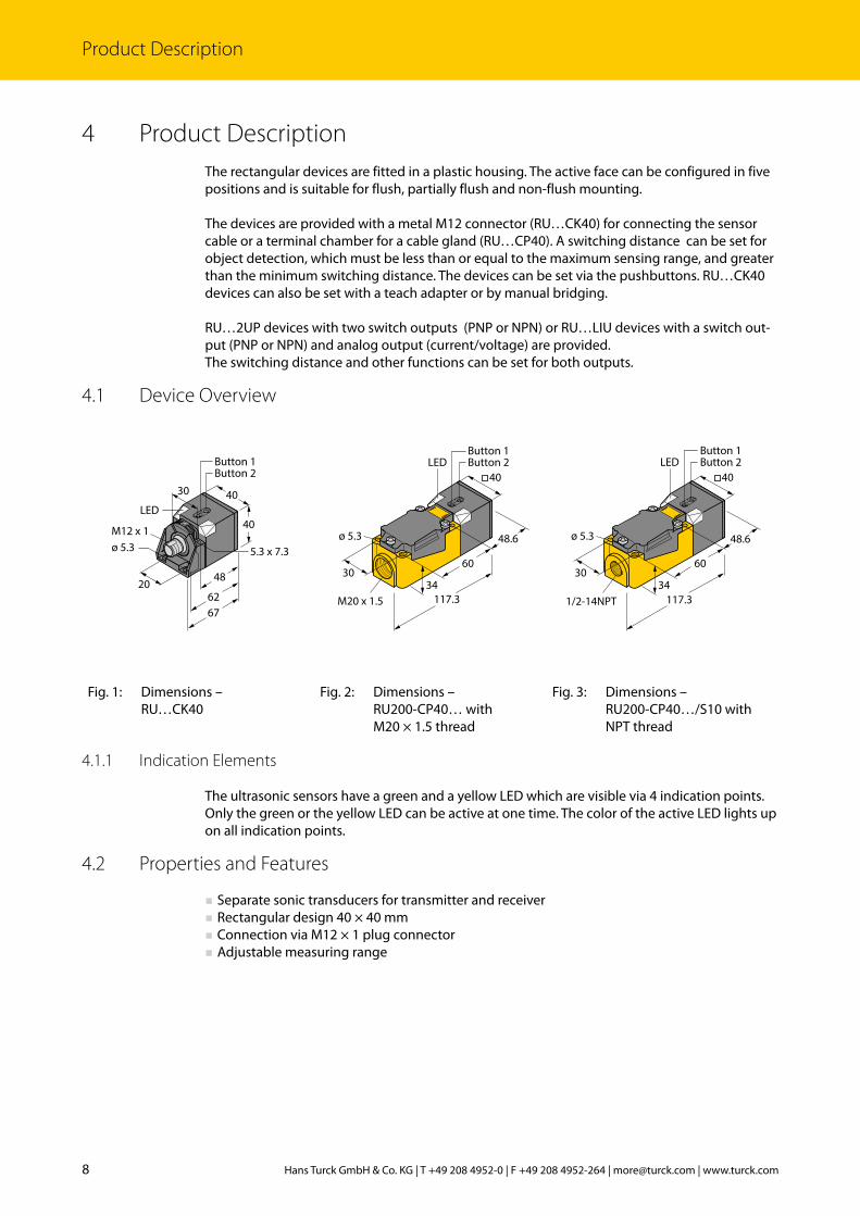
4 Product DescriptionThe rectangular devices are fitted in a plastic housing. The active face can be configured in five positions and is suitable for flush, partially flush and non-flush mounting.
The devices are provided with a metal M12 connector (RU…CK40) for connecting the sensor cable or a terminal chamber for a cable gland (RU…CP40). A switching distance can be set for object detection, which must be less than or equal to the maximum sensing range, and greater than the minimum switching distance. The devices can be set via the pushbuttons. RU…CK40 devices can also be set with a teach adapter or by manual bridging.
RU…2UP devices with two switch outputs (PNP or NPN) or RU…LIU devices with a switch out-put (PNP or NPN) and analog output (current/voltage) are provided.The switching distance and other functions can be set for both outputs.
4.1 Device Overview
40
40
30
M12 x 1
20
ø 5.3 5.3 x 7.3
6267
LED
48
Button 1Button 2
48.6
30
ø 5.3
60
117.334
40LED
Button 1Button 2
M20 x 1.5
48.6
1/2-14NPT
30
ø 5.3
60
117.334
40
Button 1Button 2LED
Fig. 1: Dimensions – RU…CK40
Fig. 2: Dimensions – RU200-CP40… with M20 × 1.5 thread
Fig. 3: Dimensions – RU200-CP40…/S10 with NPT thread
4.1.1 Indication Elements
The ultrasonic sensors have a green and a yellow LED which are visible via 4 indication points. Only the green or the yellow LED can be active at one time. The color of the active LED lights up on all indication points.
4.2 Properties and Features
■ Separate sonic transducers for transmitter and receiver ■ Rectangular design 40 × 40 mm ■ Connection via M12 × 1 plug connector ■ Adjustable measuring range
9 2017/08
4.3 Operating Principle
Ultrasonic sensors are designed for the non-contact and wear-free detection of a variety of targets by means of sound waves. It does not matter here whether the target is transparent or non-transparent, metallic or non-metallic, solid, liquid or in powder form. Environmental condi-tions such as spray, dust or rain also hardly affect the functioning of the sensors.
Ultrasonic sensors emit one or several ultrasonic pulses that are propagated in the air at the speed of sound. A part of the ultrasonic wave is reflected back to the sensor by the object. The sensor measures the total time of flight from the sensor to the object and back to the sensor. The distance to the object is then calculated with the following formula:
D = c × t / 2
D = Distance from the sensor to the object c = Speed of sound in air t = Time of flight for the ultrasonic pulse
To improve accuracy, the ultrasonic sensor forms the mean value from the measurement of several sound pulses before outputting a new value. The ultrasound velocity depends on the composition and the temperature of the gas in which the sound is propagated. In most ultra-sound applications, the composition of the gas is stable whereas the temperature may often fluctuate. The speed of sound in air varies with the temperature according to the following approxima-tion formula:
Cm/s = 20 × √273 + TC
Cm/s = Speed of sound in meters per second TC = Temperature in °C
Fluctuations in air temperature therefore affect the speed of sound, which in turn has an effect on the total time for the echo measured by the sensor. An increase in air temperature shifts both measuring range limits closer to the sensor. Conversely, both measuring range limits are shifted further away from the sensor by a drop in air temperature.This shift is approximately 3.5 % of the limit distance with a temperature change of 20 °C.Good ultrasonic reflectors are metals, glass, stone, wood with smooth and hard surfaces, as well as liquids that are aligned appropriately to the sensor. Cloth, sand or grains absorb some of the sonic energy. Foams and skins are particularly poor reflectors.
4.4 Functions and Operating Modes
The ultrasonic sensors are provided with two switching outputs that can be set independently of each other. Two switching outputs (RU200-…-2U…) or one switching output and a freely configurable output (current, voltage or switching output) (RU200-…-LIU…) are available, depending on the device variant. On devices with a freely configurable output, output 1 can be used as a switching output, and output 2 can either be used as a switching output, current output (4…20 mA/0…20 mA) or voltage output (0…10 V/0…5 V/1…6 V ).The start and end point of the measuring range can be set for the outputs. The measuring range must be within the detection range. The sensors can be run in normal operation as a diffuse mode or retro-reflective sensor. The user can set an individual switch point as well as a window or hysteresis function.
10 Hans Turck GmbH & Co. KG | T +49 208 4952-0 | F +49 208 4952-264 | [email protected] | www.turck.com
Product Description
4.4.1 Setting Options
The devices feature the following setting options:
RU…-CK40… RU…-CP40…
– Setting by manual bridging (shorting) – Setting with connected teach adapter (accessories to be ordered separately) – Setting via the pushbuttons
– Setting via the pushbuttons
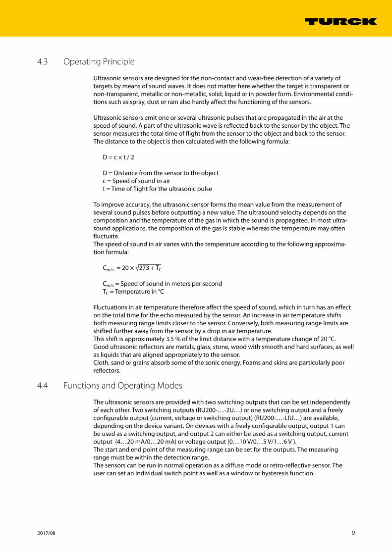
4.4.2 Diffuse Mode Sensor
When used as a diffuse mode sensor The switch window is used for window or hysteresis functions.
Diffuse Mode Sensor with NC Function
When used a diffuse mode sensor with an NC function, one switch point is taught for a switch output. The output behaves as follows:
0
1
SP1
detection rangeblindzone
Fig. 4: Diffuse mode sensor with NC function – Behavior of the switching output
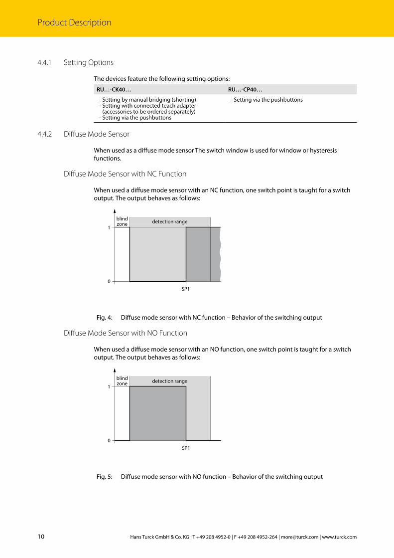
Diffuse Mode Sensor with NO Function
When used a diffuse mode sensor with an NO function, one switch point is taught for a switch output. The output behaves as follows:
0
1
SP1
detection rangeblindzone
Fig. 5: Diffuse mode sensor with NO function – Behavior of the switching output

11 2017/08
Window Function
The start and end point of the switch window range can be set for the outputs. The switch win-dow must be within the sensing range.
0
1
SP1 SP2 max
detection rangeblindzone
out
Fig. 6: Window function – Behavior of the switching output
Hysteresis Function
When using the hysteresis function, a switching window is taught that is defined by two switch points. The switching outputs have the following behavior as outputs: If an object is moved away from the sensor, the switching output is switched on for as long as the object is located between the beginning of the sensing range and the 2nd switch point. If the object passes the 2nd switch point, the switching output is switched off. If an object is moved towards the sensor, the switching output is switched off for as long as the object is located between the beginning of the sensing range and the 1st switch point. If the object passes the 1st switch point, the switching output is switched on.
0
1
switch-on switch-off
detection rangeblindzone
out out
Fig. 7: Hysteresis function – Behavior of switching output
12 Hans Turck GmbH & Co. KG | T +49 208 4952-0 | F +49 208 4952-264 | [email protected] | www.turck.com
Product Description
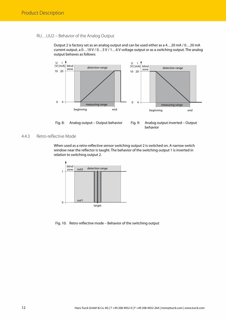
RU…LIU2 – Behavior of the Analog Output
Output 2 is factory set as an analog output and can be used either as a 4…20 mA / 0…20 mA current output, a 0…10 V / 0…5 V / 1…6 V voltage output or as a switching output. The analog output behaves as follows:
U[V]
10
0 4
I[mA]
20
beginning
detection range
measuring range
end
blindzone
U[V]
10
0 4
I[mA]
20
beginning end
detection range
measuring range
blindzone
Fig. 8: Analog output – Output behavior Fig. 9: Analog output inverted – Output behavior
4.4.3 Retro-reflective Mode
When used as a retro-reflective sensor switching output 2 is switched on. A narrow switch window near the reflector is taught. The behavior of the switching output 1 is inverted in relation to switching output 2.
0
1
target
out2
out1
detection rangeblindzone
Fig. 10: Retro-reflective mode – Behavior of the switching output
13 2017/08
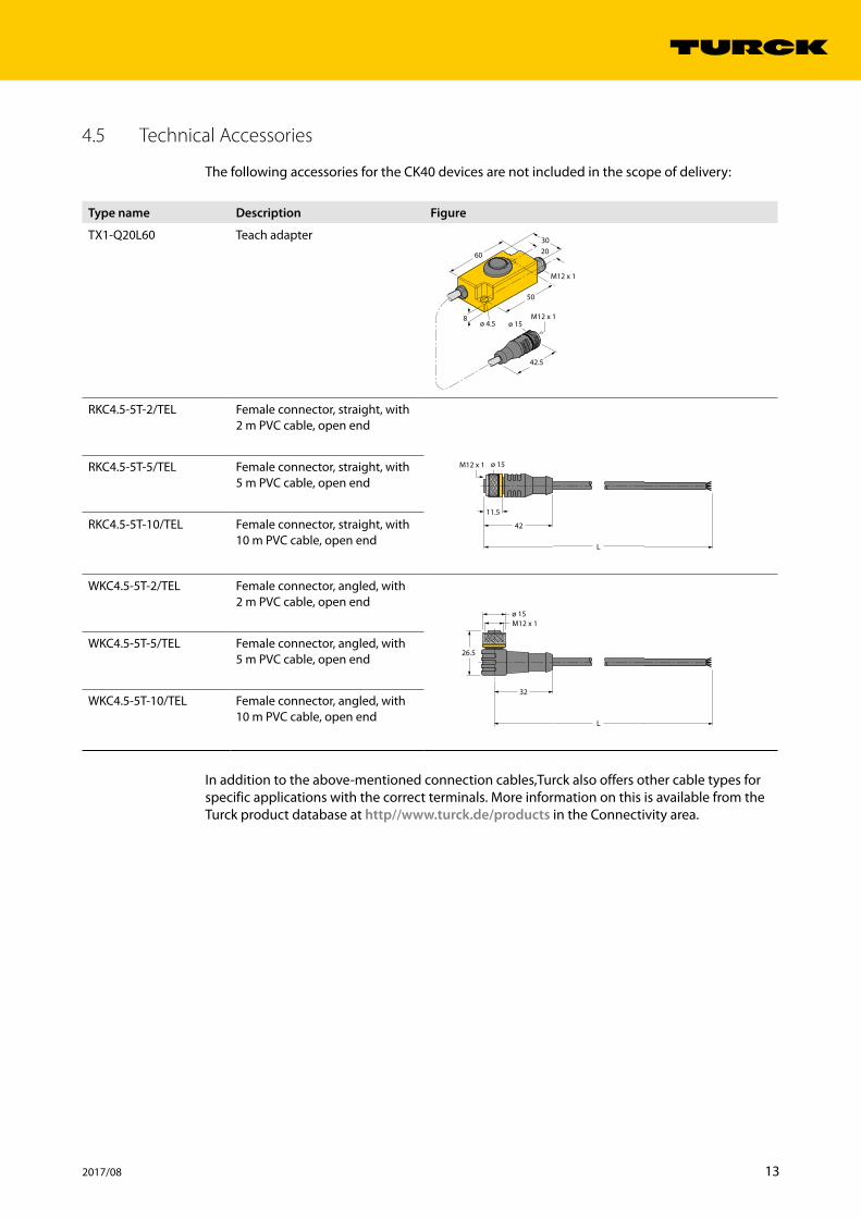
4.5 Technical Accessories
The following accessories for the CK40 devices are not included in the scope of delivery:
Type name Description Figure
TX1-Q20L60 Teach adapter60
30
50
20
M12 x 1
M12 x 1
42.5
ø 15ø 4.58
RKC4.5-5T-2/TEL Female connector, straight, with 2 m PVC cable, open end
42
11.5
ø 15M12 x 1
L
RKC4.5-5T-5/TEL Female connector, straight, with 5 m PVC cable, open end
RKC4.5-5T-10/TEL Female connector, straight, with 10 m PVC cable, open end
WKC4.5-5T-2/TEL Female connector, angled, with 2 m PVC cable, open end
26.5
M12 x 1ø 15
32
L
WKC4.5-5T-5/TEL Female connector, angled, with 5 m PVC cable, open end
WKC4.5-5T-10/TEL Female connector, angled, with 10 m PVC cable, open end
In addition to the above-mentioned connection cables,Turck also offers other cable types for specific applications with the correct terminals. More information on this is available from the Turck product database at http//www.turck.de/products in the Connectivity area.
14 Hans Turck GmbH & Co. KG | T +49 208 4952-0 | F +49 208 4952-264 | [email protected] | www.turck.com
Mounting
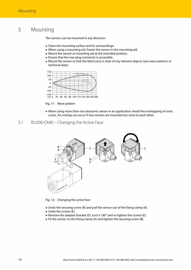
5 MountingThe sensors can be mounted in any direction.
➤ Clean the mounting surface and its surroundings.➤ When using a mounting aid: Fasten the sensor in the mounting aid.➤ Mount the sensor or mounting aid at the intended position.➤ Ensure that the rear plug connector is accessible.➤ Mount the sensor so that the blind zone is clear of any relevant objects (see wave patterns or technical data).
Fig. 11: Wave pattern
➤ When using more than one ultrasonic sensor in an application: Avoid the overlapping of sonic cones. An overlap can occur if two sensors are mounted too close to each other.
5.1 RU200-CK40 – Changing the Active Face
Fig. 12: Changing the active face
➤ Undo the securing screw (B) and pull the sensor out of the fixing clamp (A).➤ Undo the screws (E).➤ Remove the adapter bracket (D), turn it 180° and re-tighten the screws (E).➤ Fit the sensor on the fixing clamp (A) and tighten the securing screw (B).
0
-150-100
-50
50100150
0 20 40 60 80 100 110 120 140 160 200cm
100x100 mm
ø 27 mm
C C
EN 60 947-5-2
315°
AB
DE
15 2017/08
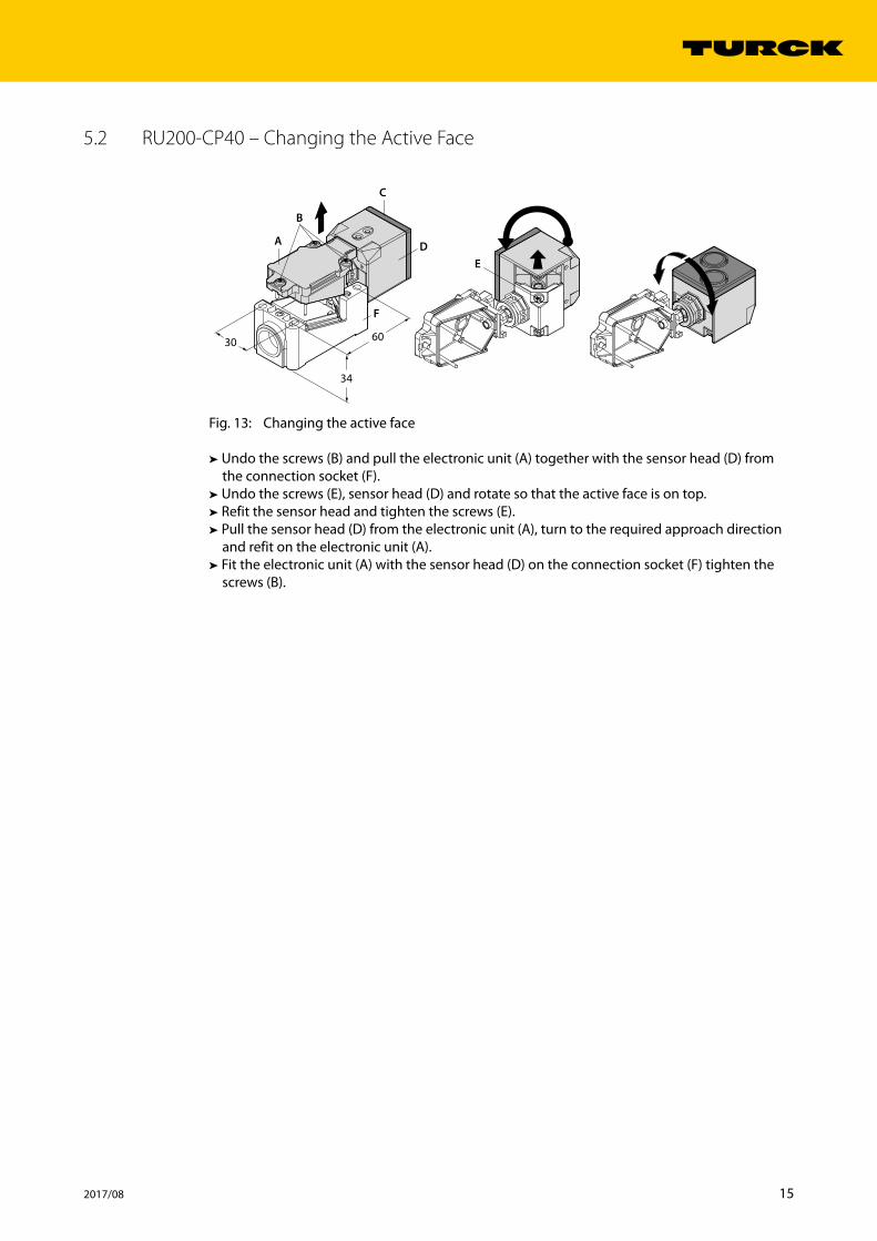
5.2 RU200-CP40 – Changing the Active Face
Fig. 13: Changing the active face
➤ Undo the screws (B) and pull the electronic unit (A) together with the sensor head (D) from the connection socket (F).
➤ Undo the screws (E), sensor head (D) and rotate so that the active face is on top.➤ Refit the sensor head and tighten the screws (E).➤ Pull the sensor head (D) from the electronic unit (A), turn to the required approach direction and refit on the electronic unit (A).
➤ Fit the electronic unit (A) with the sensor head (D) on the connection socket (F) tighten the screws (B).
B
C
D
F
E
A
60
34
30

16 Hans Turck GmbH & Co. KG | T +49 208 4952-0 | F +49 208 4952-264 | [email protected] | www.turck.com
Connection
6 Connection➤ Connect the female connector of the connection cable to the male connector of the sensor.➤ Connect the open end of the connection cable to the power supply and/or processing units.
6.1 Wiring Diagrams – RU200-CK40…Pin Pin assignment Wiring diagram
Pin 1 +24 VDC
4 BK
1 BN3 BU
2 WH
5 GY
(BU)(BN)
(WH)(BK)
+
–31
245 (GY) teach-in
Pin 2 (Out 2) PNP, NO
Pin 3 GND
Pin 4 (Out 1) PNP, NO
Pin 5 teach-in
Fig. 14: RU…-CK40-2UP8… (2 switching outputs, PNP)
Pin Pin assignment Wiring diagram
Pin 1 +24 VDC
4 BK
1 BN3 BU
2 WH
5 GY
(BU)(BN)
(WH)(BK)
+
–31
245 (GY) teach-in
Pin 2 (Out 2) NPN, NO
Pin 3 GND
Pin 4 (Out 1) NPN, NO
Pin 5 teach-in
Fig. 15: RU…-CK40-2UN8… (2 switching outputs, NPN)
Pin Pin assignment Wiring diagram
Pin 1 +24 VDC
4 BK
1 BN3 BU
2 WH
5 GY
(WH)(BN)
(BU)(BK)
+
–21
345 (GY) teach-in
analogIPin 2 (Out 2) analog
Pin 3 GND
Pin 4 (Out 1) PNP, NO
Pin 5 teach-in
Fig. 16: RU…-CK40-LIU2P8… (1 analog output, 1 switching output PNP)
Pin Pin assignment Wiring diagram
Pin 1 +24 VDC
4 BK
1 BN3 BU
2 WH
5 GY
(WH)(BN)
(BU)(BK)
+
–21
345 (GY) teach-in
analogIPin 2 (Out 2) analog
Pin 3 GND
Pin 4 (Out 1) NPN, NO
Pin 5 teach-in
Fig. 17: RU…-CK40-LIU2N8… (1 analog output, 1 switching output NPN)
17 2017/08
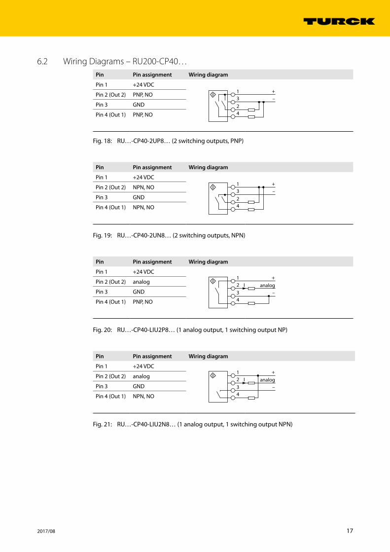
6.2 Wiring Diagrams – RU200-CP40…Pin Pin assignment Wiring diagram
Pin 1 +24 VDC
31
24
+–
Pin 2 (Out 2) PNP, NO
Pin 3 GND
Pin 4 (Out 1) PNP, NO
Fig. 18: RU…-CP40-2UP8… (2 switching outputs, PNP)
Pin Pin assignment Wiring diagram
Pin 1 +24 VDC
31
24
+–
Pin 2 (Out 2) NPN, NO
Pin 3 GND
Pin 4 (Out 1) NPN, NO
Fig. 19: RU…-CP40-2UN8… (2 switching outputs, NPN)
Pin Pin assignment Wiring diagram
Pin 1 +24 VDC+
–21
34
analogIPin 2 (Out 2) analog
Pin 3 GND
Pin 4 (Out 1) PNP, NO
Fig. 20: RU…-CP40-LIU2P8… (1 analog output, 1 switching output NP)
Pin Pin assignment Wiring diagram
Pin 1 +24 VDC+
–21
34
analogIPin 2 (Out 2) analog
Pin 3 GND
Pin 4 (Out 1) NPN, NO
Fig. 21: RU…-CP40-LIU2N8… (1 analog output, 1 switching output NPN)
18 Hans Turck GmbH & Co. KG | T +49 208 4952-0 | F +49 208 4952-264 | [email protected] | www.turck.com
Commissioning
7 CommissioningThe device is operational automatically once the cables are connected and the power supply is switched on.
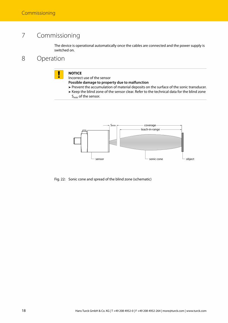
8 Operation
NOTICEIncorrect use of the sensorPossible damage to property due to malfunction
➤ Prevent the accumulation of material deposits on the surface of the sonic transducer.➤ Keep the blind zone of the sensor clear. Refer to the technical data for the blind zone Smin of the sensor.
Fig. 22: Sonic cone and spread of the blind zone (schematic)
Smin coverageteach-in-range
objectsonic conesensor
19 2017/08
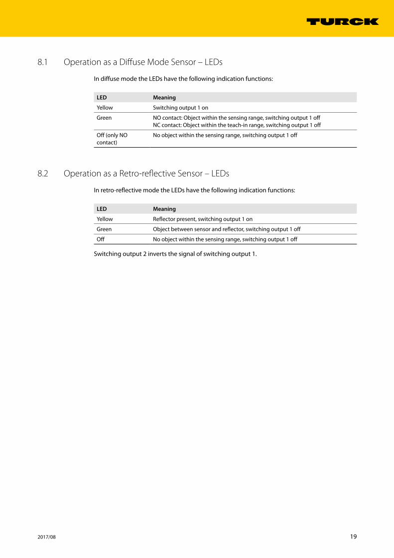
8.1 Operation as a Diffuse Mode Sensor – LEDs
In diffuse mode the LEDs have the following indication functions:
LED Meaning
Yellow Switching output 1 on
Green NO contact: Object within the sensing range, switching output 1 offNC contact: Object within the teach-in range, switching output 1 off
Off (only NO contact)
No object within the sensing range, switching output 1 off
8.2 Operation as a Retro-reflective Sensor – LEDs
In retro-reflective mode the LEDs have the following indication functions:
LED Meaning
Yellow Reflector present, switching output 1 on
Green Object between sensor and reflector, switching output 1 off
Off No object within the sensing range, switching output 1 off
Switching output 2 inverts the signal of switching output 1.

20 Hans Turck GmbH & Co. KG | T +49 208 4952-0 | F +49 208 4952-264 | [email protected] | www.turck.com
Setting
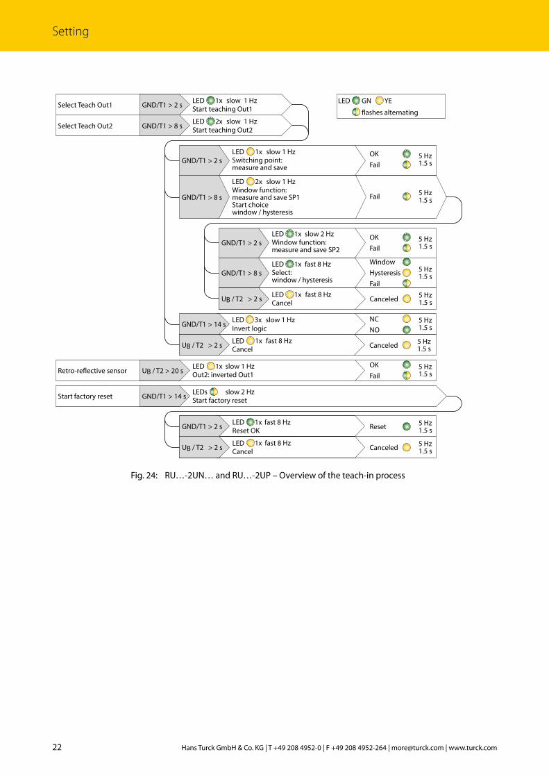
9 SettingThe ultrasonic sensor has 2 outputs with individually adjustable limits. Output 2 is factory set as an analog output on the RU…LIU devices and can be used either as a current output, a voltage output or as a switching output. The RU…2UP… devices have two switching outputs. The user can set an individual switch point as well as a double switch point for the switching outputs. The double switch point is used for window or hysteresis functions. The output behavior of the switching outputs is shown in Fig. 4 to Fig. 10. The sensor switches automatically to normal operation after the teach operation is successfully completed.
The devices can be taught with a teach adapter, via pushbuttons on the device or by manual bridging:
RU…CK40 Teach to GND Teach to UB
Teach adapter Press the pushbutton to GND Press the pushbutton to UB
Manual bridging (shorting) Bridge Pin 3 (BU) with Pin 5 (GY) Bridge Pin1 (BN) with Pin 5 (GY)
Pushbutton on the device Press pushbutton 1 Press pushbutton 2
RU…CP40 Teach to GND Teach to UB
Pushbutton on the device Press pushbutton 1 Press pushbutton 2
The TX1-Q20L60 teach adapter is not included in the scope of delivery. To use the teach adapter connect it between the sensor and the connection cable.
Abort teach operation: teach to UB for at least 2 s.
21 2017/08
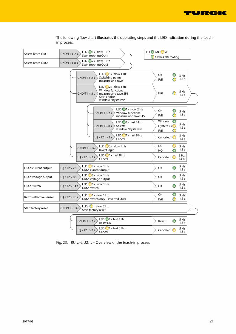
The following flow chart illustrates the operating steps and the LED indication during the teach-in process.
Fig. 23: RU…-LIU2… – Overview of the teach-in process
GND/T1 > 8 s
GND/T1 > 2 s
UB / T2 > 14 s
UB / T2 > 8 s
UB / T2 > 2 s
LED
LED
LEDGND/T1 > 14 s
UB / T2 > 20 s
UB / T2 > 2 s
GND/T1 > 2 s
GND/T1 > 14 s
LED
LED
GND/T1 > 8 s
GND/T1 > 2 s
GND/T1 > 8 s
GND/T1 > 2 s
LED
LED
LED
LED
LED
LED
LEDs
LED
LED
UB / T2 > 2 s LED
UB / T2 > 2 s LED
GN YELED1x
2x
1x
1x
1x
1x
3x
1x
1x
1x
1x
1x
2x
3x
2x slow 1 Hz
slow 1 Hz
fast 8 Hz
slow 1 Hz
slow 1 Hz
slow 2 Hz
slow 1 Hz
slow 1 Hz
slow 1 Hz
slow 1 Hz
slow 1 Hz
fast 8 Hz
fast 8 Hz
flashes alternating
Select:window / hysteresis
Window function:measure and save SP2
FailHysteresisWindow
Canceled
Reset
OKOut2: switch
Out2: voltage output
Out2: current output
Start factory reset
Select Teach Out2
Select Teach Out1
Out2: switch
OKOut2: voltage output
OKOut2: current output
FailOK
fast 8 Hz
fast 8 Hz
slow 2 Hz
Fail
NONC
Fail5 Hz1.5 s
5 Hz1.5 s
5 Hz1.5 s
5 Hz1.5 s
5 Hz1.5 s
5 Hz1.5 s
5 Hz1.5 s
5 Hz1.5 s
5 Hz1.5 s
5 Hz1.5 s
5 Hz1.5 s
OK
Invert logic
Retro-reflective sensorFailOK
Out2: switch only – inverted Out1
Cancel
Canceled 5 Hz1.5 sCancel
Canceled 5 Hz1.5 sCancel
Reset OK
Start factory reset
Window function:measure and save SP1Start choicewindow / hysteresis
Switching point:measure and save
Start teaching Out2
Start teaching Out1
22 Hans Turck GmbH & Co. KG | T +49 208 4952-0 | F +49 208 4952-264 | [email protected] | www.turck.com
Setting
Fig. 24: RU…-2UN… and RU…-2UP – Overview of the teach-in process
GND/T1 > 8 s
GND/T1 > 2 s
LED
LED
LEDGND/T1 > 14 s
UB / T2 > 20 s
UB / T2 > 2 s
GND/T1 > 2 s
GND/T1 > 14 s
LED
LED
GND/T1 > 8 s
GND/T1 > 2 s
GND/T1 > 8 s
GND/T1 > 2 s
LED
LED
LED
LED
LED
LEDs
UB / T2 > 2 s LED
UB / T2 > 2 s LED
GN YELED1x
2x
1x
1x
1x
1x
3x
1x
1x
1x
1x
2x slow 1 Hz
slow 1 Hz
fast 8 Hz
slow 1 Hz
slow 1 Hz
slow 2 Hz
slow 1 Hz
slow 1 Hz
fast 8 Hz
fast 8 Hz
flashes alternating
Select:window / hysteresis
Window function:measure and save SP2
FailHysteresisWindow
Canceled
Reset
Start factory reset
Select Teach Out2
Select Teach Out1
FailOK
fast 8 Hz
fast 8 Hz
slow 2 Hz
Fail
NONC
Fail5 Hz1.5 s
5 Hz1.5 s
5 Hz1.5 s
5 Hz1.5 s
5 Hz1.5 s
5 Hz1.5 s
5 Hz1.5 s
5 Hz1.5 s
OK
Invert logic
Retro-reflective sensorFailOK
Out2: inverted Out1
Cancel
Canceled 5 Hz1.5 sCancel
Canceled 5 Hz1.5 sCancel
Reset OK
Start factory reset
Window function:measure and save SP1Start choicewindow / hysteresis
Switching point:measure and save
Start teaching Out2
Start teaching Out1

23 2017/08
9.1 RU200-CK40 – Setting via Teach Adapter
Selecting the Output
➤ Select switching output 1: Press and hold down the pushbutton on the adapter to GND for 2…7 s.
➤ Select output 2: Press and hold down the pushbutton on the adapter to GND for 8…13 s.
Setting the Switch Point
➤ Connect the TX1-Q20L60 teach adapter between the sensor and the connection cable.➤ Select the switching output.➤ Position the object for the switch point.➤ Save the switch point: Press and hold down the pushbutton on the adapter to GND for 2…7 s.➥ The individual switch point has been taught successfully if the green LED flashes for 1.5 s at a frequency of 5 Hz.
Window Function – Setting the Switching Range
➤ Connect the TX1-Q20L60 teach adapter between the sensor and the connection cable.➤ Position the object for switch point 1.➤ Select the switching output.➤ Save switch point 1: Press and hold down the pushbutton on the adapter to GND for 8…13 s.➤ Position the object for switch point 2.➤ Save switch point 2: Press and hold down the pushbutton on the adapter to GND for 2…7 s.➥ The switch points have been successfully taught if the green LED flashes for 1.5 s at a frequen-cy of 5 Hz.
Window Function – Switching between Hysteresis and Window
➤ Connect the TX1-Q20L60 teach adapter between the sensor and the connection cable.➤ Position the object at any point in the sensing range.➤ Press and hold down the pushbutton on the adapter to GND for 8…13 s.➤ Press and hold down the pushbutton on the adapter to GND for 8…13 s.➥ The individual switch point has been taught successfully if the green LED flashes for 1.5 s at a frequency of 5 Hz.
➥ The hysteresis function has been taught successfully if the yellow LED flashes for 1.5 s at a frequency of 5 Hz.
Inverting the Output Function (NO/NC)
➤ Connect the TX1-Q20L60 teach adapter between the sensor and the connection cable.➤ Select the switching output.➤ Press and hold down the pushbutton on the adapter to GND for 14…19 s.➥ The output function has been successfully inverted as an NO contact if the green LED flashes for 1.5 s at a frequency of 5 Hz.
➥ The output function has been successfully inverted as an NC contact if the yellow LED flashes for 1.5 s at a frequency of 5 Hz.
Setting Operation as a Retro-reflective Sensor
➤ Connect the TX1-Q20L60 teach adapter between the sensor and the connection cable.➤ Position the reflector in the sensing range.➤ Press and hold down the pushbutton on the adapter to UB for at least 21…s.➥ The sensor is set successfully as a retro-reflective sensor if the green LED flashes for 1.5 s at a frequency of 5 Hz.
24 Hans Turck GmbH & Co. KG | T +49 208 4952-0 | F +49 208 4952-264 | [email protected] | www.turck.com
Setting
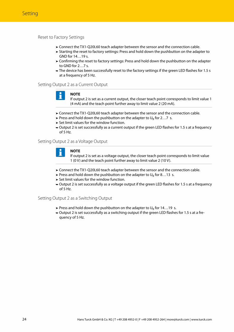
Reset to Factory Settings
➤ Connect the TX1-Q20L60 teach adapter between the sensor and the connection cable.➤ Starting the reset to factory settings: Press and hold down the pushbutton on the adapter to GND for 14…19 s.
➤ Confirming the reset to factory settings: Press and hold down the pushbutton on the adapter to GND for 2…7 s.
➥ The device has been successfully reset to the factory settings if the green LED flashes for 1.5 s at a frequency of 5 Hz.
Setting Output 2 as a Current Output
NOTEIf output 2 is set as a current output, the closer teach point corresponds to limit value 1 (4 mA) and the teach point further away to limit value 2 (20 mA).
➤ Connect the TX1-Q20L60 teach adapter between the sensor and the connection cable.➤ Press and hold down the pushbutton on the adapter to UB for 2…7 s.➤ Set limit values for the window function. ➥ Output 2 is set successfully as a current output if the green LED flashes for 1.5 s at a frequency of 5 Hz.
Setting Output 2 as a Voltage Output
NOTEIf output 2 is set as a voltage output, the closer teach point corresponds to limit value 1 (0 V) and the teach point further away to limit value 2 (10 V).
➤ Connect the TX1-Q20L60 teach adapter between the sensor and the connection cable. ➤ Press and hold down the pushbutton on the adapter to UB for 8…13 s.➤ Set limit values for the window function. ➥ Output 2 is set successfully as a voltage output if the green LED flashes for 1.5 s at a frequency of 5 Hz.
Setting Output 2 as a Switching Output
➤ Press and hold down the pushbutton on the adapter to UB for 14…19 s.➥ Output 2 is set successfully as a switching output if the green LED flashes for 1.5 s at a fre-quency of 5 Hz.
25 2017/08
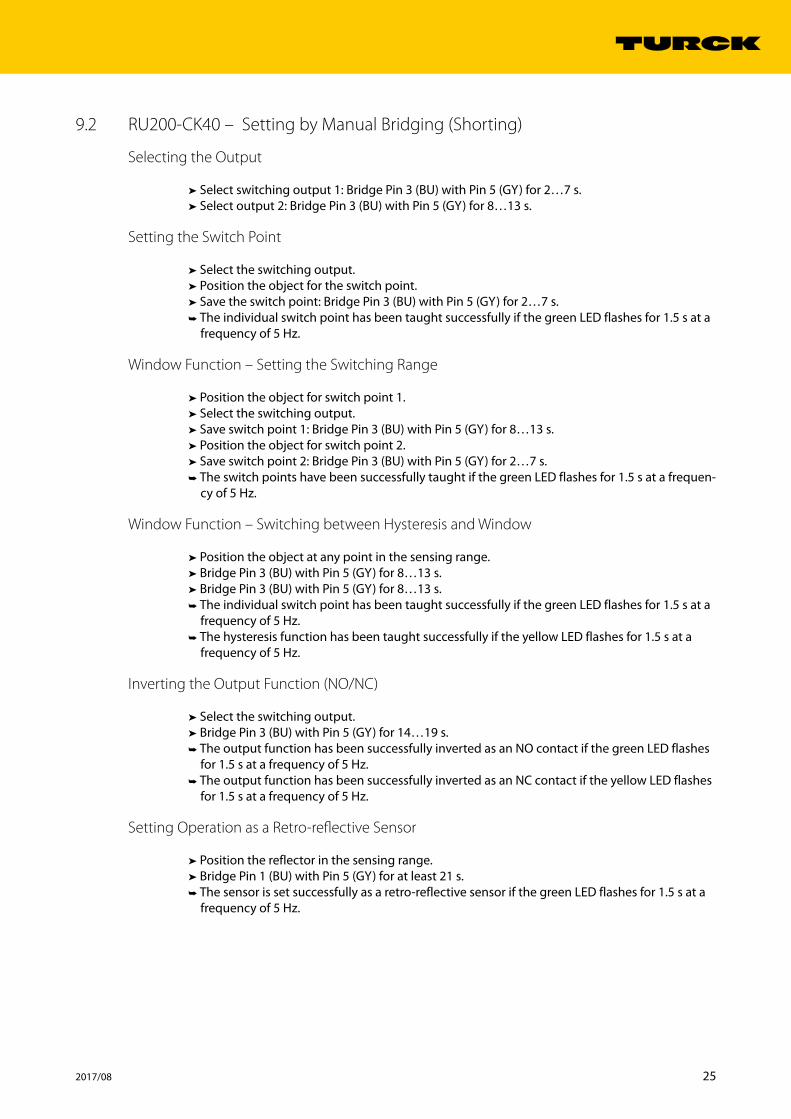
9.2 RU200-CK40 – Setting by Manual Bridging (Shorting)
Selecting the Output
➤ Select switching output 1: Bridge Pin 3 (BU) with Pin 5 (GY) for 2…7 s.➤ Select output 2: Bridge Pin 3 (BU) with Pin 5 (GY) for 8…13 s.
Setting the Switch Point
➤ Select the switching output.➤ Position the object for the switch point.➤ Save the switch point: Bridge Pin 3 (BU) with Pin 5 (GY) for 2…7 s.➥ The individual switch point has been taught successfully if the green LED flashes for 1.5 s at a frequency of 5 Hz.
Window Function – Setting the Switching Range
➤ Position the object for switch point 1.➤ Select the switching output.➤ Save switch point 1: Bridge Pin 3 (BU) with Pin 5 (GY) for 8…13 s.➤ Position the object for switch point 2.➤ Save switch point 2: Bridge Pin 3 (BU) with Pin 5 (GY) for 2…7 s.➥ The switch points have been successfully taught if the green LED flashes for 1.5 s at a frequen-cy of 5 Hz.
Window Function – Switching between Hysteresis and Window
➤ Position the object at any point in the sensing range.➤ Bridge Pin 3 (BU) with Pin 5 (GY) for 8…13 s.➤ Bridge Pin 3 (BU) with Pin 5 (GY) for 8…13 s.➥ The individual switch point has been taught successfully if the green LED flashes for 1.5 s at a frequency of 5 Hz.
➥ The hysteresis function has been taught successfully if the yellow LED flashes for 1.5 s at a frequency of 5 Hz.
Inverting the Output Function (NO/NC)
➤ Select the switching output.➤ Bridge Pin 3 (BU) with Pin 5 (GY) for 14…19 s.➥ The output function has been successfully inverted as an NO contact if the green LED flashes for 1.5 s at a frequency of 5 Hz.
➥ The output function has been successfully inverted as an NC contact if the yellow LED flashes for 1.5 s at a frequency of 5 Hz.
Setting Operation as a Retro-reflective Sensor
➤ Position the reflector in the sensing range.➤ Bridge Pin 1 (BU) with Pin 5 (GY) for at least 21 s.➥ The sensor is set successfully as a retro-reflective sensor if the green LED flashes for 1.5 s at a frequency of 5 Hz.
26 Hans Turck GmbH & Co. KG | T +49 208 4952-0 | F +49 208 4952-264 | [email protected] | www.turck.com
Setting
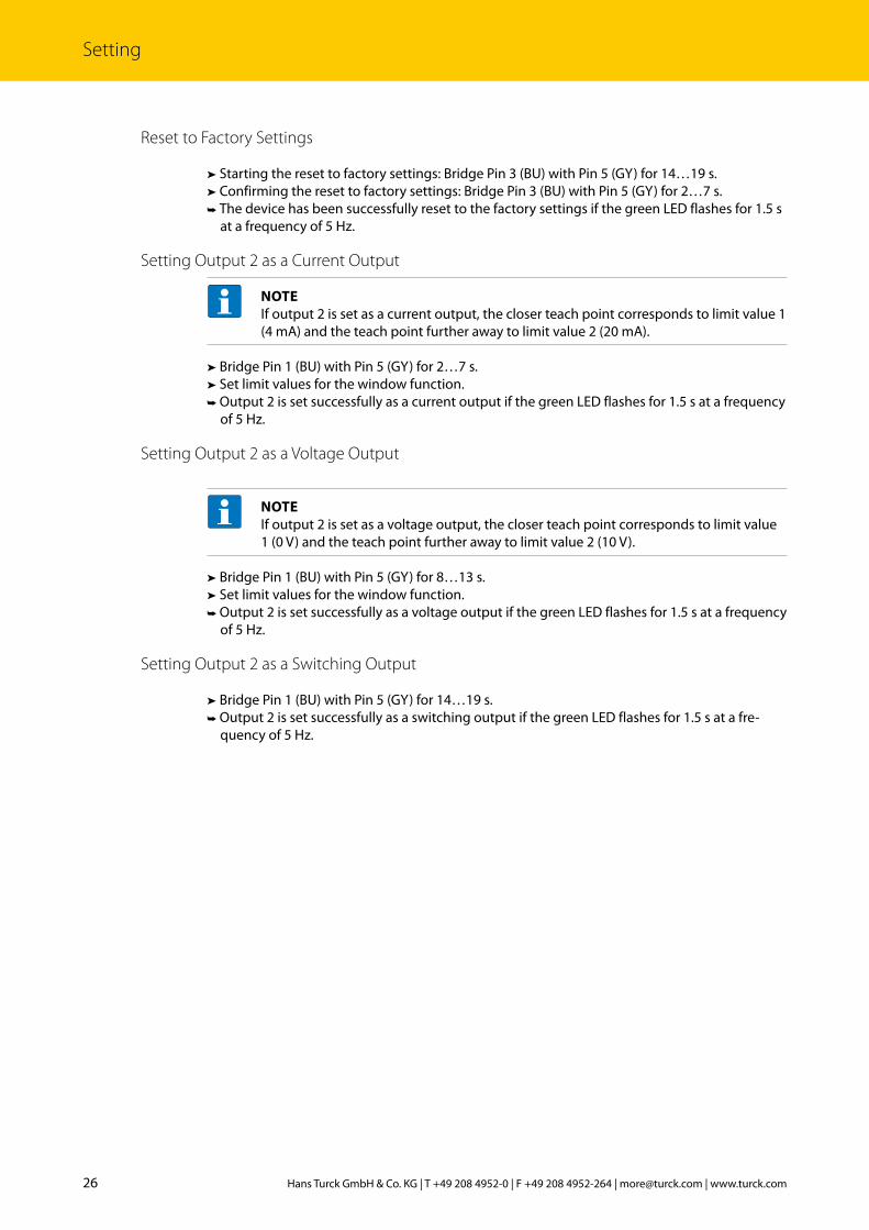
Reset to Factory Settings
➤ Starting the reset to factory settings: Bridge Pin 3 (BU) with Pin 5 (GY) for 14…19 s.➤ Confirming the reset to factory settings: Bridge Pin 3 (BU) with Pin 5 (GY) for 2…7 s.➥ The device has been successfully reset to the factory settings if the green LED flashes for 1.5 s at a frequency of 5 Hz.
Setting Output 2 as a Current Output
NOTEIf output 2 is set as a current output, the closer teach point corresponds to limit value 1 (4 mA) and the teach point further away to limit value 2 (20 mA).
➤ Bridge Pin 1 (BU) with Pin 5 (GY) for 2…7 s.➤ Set limit values for the window function. ➥ Output 2 is set successfully as a current output if the green LED flashes for 1.5 s at a frequency of 5 Hz.
Setting Output 2 as a Voltage Output
NOTEIf output 2 is set as a voltage output, the closer teach point corresponds to limit value 1 (0 V) and the teach point further away to limit value 2 (10 V).
➤ Bridge Pin 1 (BU) with Pin 5 (GY) for 8…13 s.➤ Set limit values for the window function. ➥ Output 2 is set successfully as a voltage output if the green LED flashes for 1.5 s at a frequency of 5 Hz.
Setting Output 2 as a Switching Output
➤ Bridge Pin 1 (BU) with Pin 5 (GY) for 14…19 s.➥ Output 2 is set successfully as a switching output if the green LED flashes for 1.5 s at a fre-quency of 5 Hz.

27 2017/08
9.3 RU200-CK40 and RU200-CP40 – Setting via Pushbuttons
NOTEThe devices with a teach button are ready for teaching up to 300 s after the power sup-ply is switched on. The teach button is then automatically locked. A new teach opera-tion is only possible after the power supply has been reset.
Selecting the Output
➤ Select switching output 1: Press and hold down pushbutton 1 for 2…7 s.➤ Select output 2: Press and hold down pushbutton 1 for 8…13 s.
Setting the Switch Point
➤ Select the switching output.➤ Position the object for the switch point.➤ Save the switch point: Press and hold down pushbutton 1 for 2…7 s.➥ The individual switch point has been taught successfully if the green LED flashes for 1.5 s at a frequency of 5 Hz.
Window Function – Setting the Switching Range
➤ Position the object for switch point 1.➤ Select the switching output. ➤ Save switch point 1: Press and hold down pushbutton 1 for 8…13 s.➤ Position the object for switch point 2.➤ Save switch point 2: Press and hold down pushbutton 1 for 2…7 s.➥ The switch points have been successfully taught if the green LED flashes for 1.5 s at a frequen-cy of 5 Hz.
Window Function – Switching between Hysteresis and Window
➤ Position the object at any point in the sensing range.➤ Press and hold down pushbutton 1 for 8…13 s.➤ Press and hold down pushbutton 1 once more for 8…13s.➥ The individual switch point has been taught successfully if the green LED flashes for 1.5 s at a frequency of 5 Hz.
➥ The hysteresis function has been taught successfully if the yellow LED flashes for 1.5 s at a frequency of 5 Hz.
Inverting the Output Function (NO/NC)
➤ Select the switching output. ➤ Press and hold down pushbutton 1 for 14…19 s.➥ The output function has been successfully inverted as an NO contact if the green LED flashes for 1.5 s at a frequency of 5 Hz.
➥ The output function has been successfully inverted as an NC contact if the yellow LED flashes for 1.5 s at a frequency of 5 Hz.
Setting Operation as a Retro-reflective Sensor
➤ Position the reflector in the sensing range.➤ Press and hold down pushbutton 2 for at least 21…s.➥ The sensor is set successfully as a retro-reflective sensor if the green LED flashes for 1.5 s at a frequency of 5 Hz.
28 Hans Turck GmbH & Co. KG | T +49 208 4952-0 | F +49 208 4952-264 | [email protected] | www.turck.com
Troubleshooting
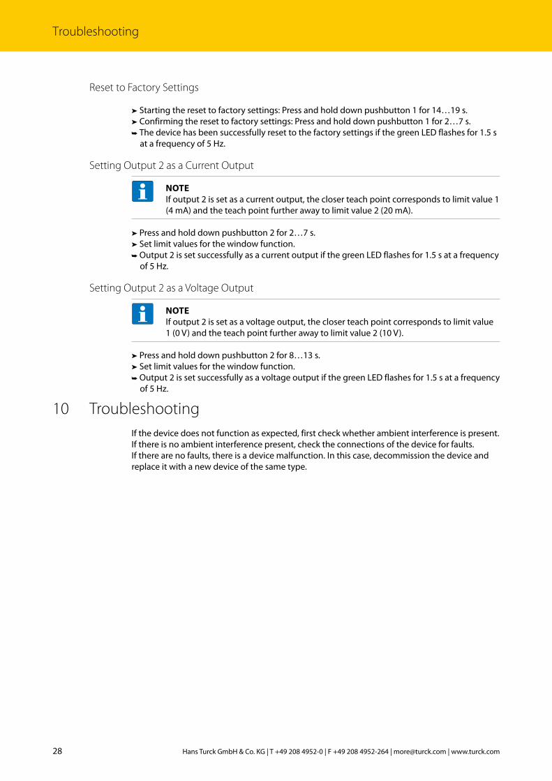
Reset to Factory Settings
➤ Starting the reset to factory settings: Press and hold down pushbutton 1 for 14…19 s.➤ Confirming the reset to factory settings: Press and hold down pushbutton 1 for 2…7 s.➥ The device has been successfully reset to the factory settings if the green LED flashes for 1.5 s at a frequency of 5 Hz.
Setting Output 2 as a Current Output
NOTEIf output 2 is set as a current output, the closer teach point corresponds to limit value 1 (4 mA) and the teach point further away to limit value 2 (20 mA).
➤ Press and hold down pushbutton 2 for 2…7 s.➤ Set limit values for the window function. ➥ Output 2 is set successfully as a current output if the green LED flashes for 1.5 s at a frequency of 5 Hz.
Setting Output 2 as a Voltage Output
NOTEIf output 2 is set as a voltage output, the closer teach point corresponds to limit value 1 (0 V) and the teach point further away to limit value 2 (10 V).
➤ Press and hold down pushbutton 2 for 8…13 s.➤ Set limit values for the window function. ➥ Output 2 is set successfully as a voltage output if the green LED flashes for 1.5 s at a frequency of 5 Hz.
10 TroubleshootingIf the device does not function as expected, first check whether ambient interference is present. If there is no ambient interference present, check the connections of the device for faults.If there are no faults, there is a device malfunction. In this case, decommission the device and replace it with a new device of the same type.
29 2017/08
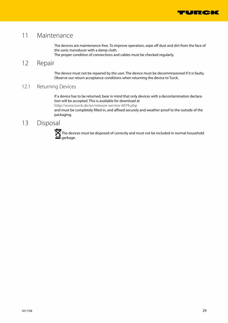
11 MaintenanceThe devices are maintenance-free. To improve operation, wipe off dust and dirt from the face of the sonic transducer with a damp cloth.The proper condition of connections and cables must be checked regularly.
12 RepairThe device must not be repaired by the user. The device must be decommissioned if it is faulty. Observe our return acceptance conditions when returning the device to Turck.
12.1 Returning Devices
If a device has to be returned, bear in mind that only devices with a decontamination declara-tion will be accepted. This is available for download at http://www.turck.de/en/retoure-service-6079.phpand must be completely filled in, and affixed securely and weather-proof to the outside of the packaging.
13 DisposalThe devices must be disposed of correctly and must not be included in normal household garbage.
30 Hans Turck GmbH & Co. KG | T +49 208 4952-0 | F +49 208 4952-264 | [email protected] | www.turck.com
Technical Data
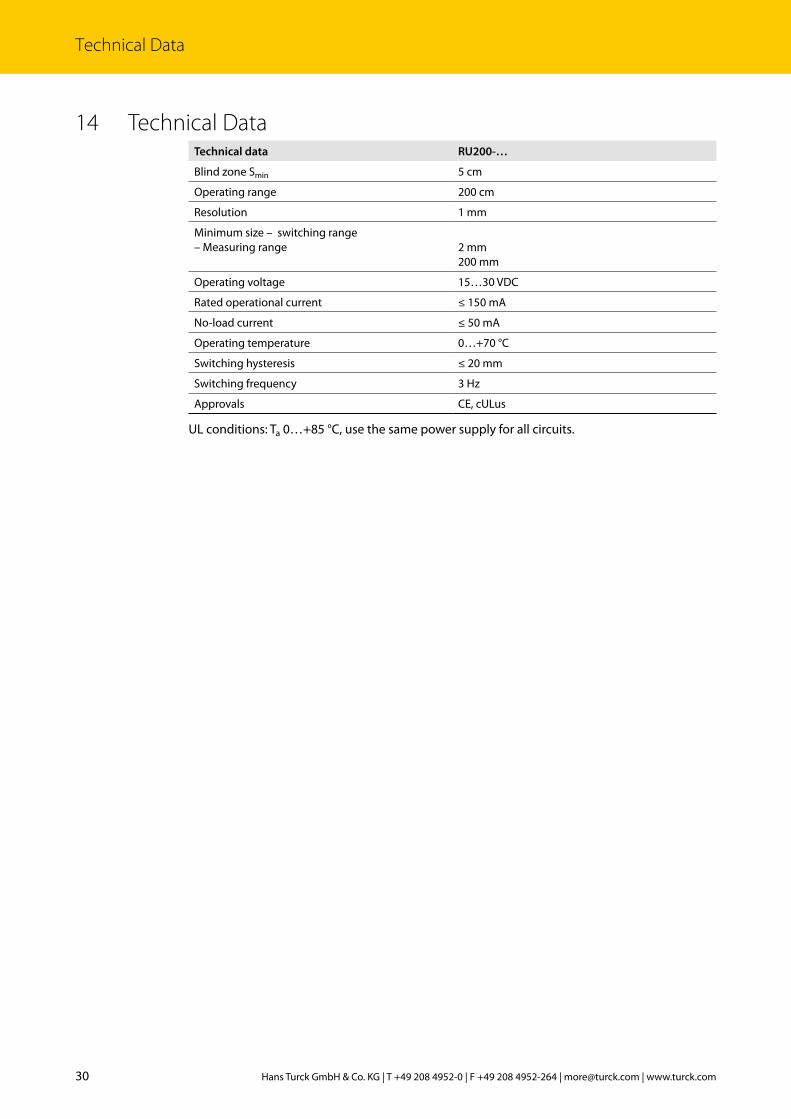
14 Technical DataTechnical data RU200-…
Blind zone Smin 5 cm
Operating range 200 cm
Resolution 1 mm
Minimum size – switching range– Measuring range
2 mm 200 mm
Operating voltage 15…30 VDC
Rated operational current ≤ 150 mA
No-load current ≤ 50 mA
Operating temperature 0…+70 °C
Switching hysteresis ≤ 20 mm
Switching frequency 3 Hz
Approvals CE, cULus
UL conditions: Ta 0…+85 °C, use the same power supply for all circuits.

31 2017/08

100001118 | 2017/08
*100001118*
28 subsidiaries and over 60 representations worldwide!
www.turck.com