rulebook on the tecnical and exploatation conditions for the
TRANSCRIPT
AGENCY FOR ELECTRONIC COMMUNICATIONS AND POSTAL SERVICES
RULEBOOK on the tecnical and exploatation conditions for the frequency modulated
emissions of the broadcasting stations
Podgorica, April 2010

2
Further to Article 8, paragraph 1, item 7 and 19, Article 62, paragraph 2, Article 76, paragraph 1, item 2 and
3 and Article 134, paragraph 1, item 2 of the Law on Electronic Communications ("Official Gazette of
Montenegro", No 50/08 and 70/09), the Council of the Agency for Electronic Communications and Postal
Services, at its session of 08. 04. 2010 enacts the
RULEBOOK on the tecnical and exploatation conditions for the frequency modulated emissions of
the broadcasting stations
I General provisions
(Scope) Article 1
This rulebook stipulates technical characteristics of the sound broadcasting radio stations transmitting
frequency modulated signal within VHF band 87.5 – 108 MHz, as well as normatives for operation,
transmittion and efficient use of radio-frequency spectrum.
(Testing and marking of equipment) Article 2
Radio stations from Aricle 1 shall be used if meet conformity conditions set by this rulebook.
Provisions of this rulebook stipulate conditions obligatory for manufacturers, person or entities responsible
for placing the equipment on the market.
For all radio stations from Article 1 of this rulebook, conformity tests shall be carried out and equipment
marked with initials "CE" in accordance with Directive 1999/5/EC of the European Parliament and of the
Council of 9 March 1999 on radio equipment and telecommunications terminal equipment and the mutual
recognition of their conformity.
(Normative References) Article 3
Sound broadcasting radio stations transmitting frequency modulated signals shall be compliant with the following
standards, recommendations and other international normative references:
- ITU-R Recommendation BS.450-3 - "Transmission standards for FM sound broadcasting at VHF"
- ITU-R Recommendation BS.468-4 - "Measurement of audio-frequency noise voltage level in sound
broadcasting"
- ETSI ETS 300 384 - "Radio broadcasting systems; Very high frequency (VHF), frequency modulated,
sound broadcasting transmitters"
- ETSI EN 302 018-2 - "Electromagnetic Compatibility and Radio Spectrum Matters (ERM);
Transmitting Equipment for the Frequency Modulated (FM) Sound Broadcasting Service; Part 2:
Harmonized EN Under Article 3.2 of the R&TTE Directive".
Methods of measurement stipulating from this rulebook shall be in accordance with normatives given by the
following standards, unless otherwise stated:
- EN 60244-1:2000 - Methods of measurement for radio transmitters - Part 1: General characteristics for
broadcast transmitters
3
- IEC 60244-2 Ed.1.0 b:1969; IEC 60244-2A Ed.1.0 b:1969; IEC 60244-2B Ed.1.0 b:1969; IEC 60244-2A
Amd.1 Ed.1.0 b:1973; IEC 60244-2 Amd.1 Ed.1.0 b:1974; - Methods of measurement for radio
transmitters. Part 2: Bandwidth, out-of-band power and power of non-essential oscillations
- EN 60244-13:1993 - Methods of measurement for radio transmitters - Part 13: Performance
characteristics for FM sound broadcasting.
The transmitter may incorporate stereo coder. Radio Data System shall be incorporated within transmitter, but
conformity test performed separately, in accordance with standard:
- IEC 62106 Ed. 2.0 EN 2009 - "Specification of the Radio Data System (RDS) for VHF/FM sound
broadcasting in the frequency range from 87,5 MHz to 108,0 MHz".
(Definitions and abbreviation) Article 4
For the purposes of this rulebook the following definitions apply:
1. Very High Frequency (VHF) Frequency Modulation (FM) sound broadcasting transmitter: Radio
station broadcasting sound signal, operating in the frequency band 87,5 MHz to 108 MHz, in accordance
with ITU regional agreement Geneva 84 (Frequency Assignment Plan for FM Sound Broadcasting
Stations in Region 1 and Part of Region 3 in the Band 87,5-108 MHz) as well as technical and operating
conditions and normative acts stipulating by this rulebook and Frequency Assignment Plan for FM
Sound Broadcasting Stations in Montenegro.
2. Out-of-band emissions: Emission on a frequency or frequencies immediately outside the necessary
bandwidth which results from the modulation process, but excluding spurious emissions.
3. Spurious emissions: Emission on a frequency or frequencies which are outside the necessary bandwidth
and the level of which may be reduced without affecting the corresponding transmission of information.
Spurious emissions include harmonic emissions, parasitic emissions, intermodulation products and
frequency conversion products but exclude out of band emissions.
4. Unwanted emissions: Consist of spurious emissions and out of band emissions.
5. Necessary bandwidth: Bandwith of emission necessary for signal transmittion with required rate and
quality, under specified conditions.
6. Shielding radiation: Radiation not caused by antenna.
7. Standing wave ratio (voltage standing wave ratio, mismatch ratio): Is determined by equation:
r
r
U
UVSWR
−
+
==
1
1
min
max , where r
absolute value of reflection coefficient.
8. Reflected wave attenuation: Reflected wave attenuation is determined by equation: -20logr
.
9. Signal L: Signal L corresponds to the information in the left channel.
10. Signal R: Signal R corresponds to the information in the right channel.
11. Sum signal M: M=(L+R)/2; this information is also the signal for the monophonic receiver.
12. Difference signal S: S=(L-R)/2; this information allows the stereo-receiver to regain signals L and R in
conjunction with the M signal.
13. Multiplex (MPX) signal: This signal contains all information, including the pilot tone and any
supplementary signal which is used to frequency modulate the VHF FM transmitter.
14. Stereo subcarrier (38 kHz): The subcarrier (38 kHz) converts the S signal to the carrier-frequency
position (23 kHz - 53 kHz).
15. Pilot tone (19 kHz): The pilot tone (19 kHz) is used to regain the stereo subcarrier in the stereo-receiver.
16. Radio Data System (RDS): RDS is a signal containing information on programmes and broadcasting
network. This signal is carried by a subcarrier at 57 kHz, amplitude modulated by the encoded data with
suppressed carrier in a frequency band of ± 2,4 kHz.
17. Supplementary signal: This signal can operate in the range between 53 kHz and 76 kHz.
18. AF: audio frequency or LF: low frequency.
4
19. RF: radio frequency or HF: high frequency.
20. Input level 0 dBu (0,775 V): Corresponds to level 0 dBm (1 mV) / 600 Ω. 21. dBc: signal level in relation to level of unmodulated carrier.
22. Psophometric filter: Device that can be used for measurement of signal/noise ratio, taking into account
subjective assessment of receiving signal quality.
23. Pre-emphasis: system process designed to increase, within a frequency band, the magnitude of higher)
with respect to lower frequencies in order to improve the overall signal-to-noise ratio The pre-emphasis
characteristic of the sound signal is identical to the admittance-frequency curve of a parallel resistance-
capacitance circuit having a time constant of 50 µs.
24. De-emphasis: on the receiving side, process inverse to pre-emphasis.
II Transmission standards for FM sound broadcasting at VHF
Article 5 1. Monophonic transmissions Radio-frequency (RF) signal The RF signal consists of a carrier frequency-modulated by the sound signal to be transmitted, after pre-
emphasis, with a maximum frequency deviation equal to ± 75 kHz.
Pre-emphasis of the sound signal The pre-emphasis characteristic of the sound signal is identical to the admittance-frequency curve of a
parallel resistance-capacitance circuit having a time constant of 50 µs.
2 . Stereophonic transmissions Frequency-modulated stereophonic broadcasting transmissions within the band 87,5-108 MHz use pilot tone
system.
RF signal The RF signal consists of a carrier frequency-modulated by a baseband signal, known in this case as the
"stereophonic multiplex signal", with a maximum frequency deviation equal to ± 75 kHz.
Stereophonic multiplex signal – MPX is the sum of:
a. the pre-emphasized signal, M;
b. the sidebands of the suppressed sub-carrier amplitude modulated by the pre-emphasized signal, S;
c. pilot signal, with a frequency of 19 kHz exactly one-half the sub-carrier frequency.
The amplitudes of the various components of the MPX signal The amplitudes of the various components of the stereophonic multiplex signals referred to the maximum
amplitude of that signal (which corresponds to the maximum frequency deviation) are:
a. signal M : maximum value 90% (A and B being equal and in phase);
b. signal S : maximum value of the sum of the amplitudes of the two sidebands: 90% (which corresponds
to A and B being equal and of opposite phase);
c. pilot signal: 8 to 10%;
d. sub-carrier at 38 kHz suppressed: maximum residual amplitude 1%.
Relative phase The relative phase of the pilot signal and the sub-carrier is such that, when the transmitter is modulated by a
multiplex signal for which L is positive and R = -L, this signal crosses the time axis with a positive slope each

5
time the pilot signal has an instantaneous value of zero. The phase tolerance of the pilot signal should not
exceed ± 3° from the above state.
Value of the multiplex signal Positive value of the multiplex signal corresponds to a positive frequency deviation of the main carrier.
3. Baseband signal in the case of a supplementary signal transmission If, in addition to the monophonic or stereophonic programme, a supplementary monophonic programme
and/or supplementary information signals are transmitted and the maximum frequency deviation is ± 75
kHz, the following additional conditions must be met:
a. The insertion of the supplementary programme or signals in the baseband signal must permit
compatibility with existing receivers, i.e. these additional signals must not affect the reception
quality of the main monophonic or stereophonic programmes.
b. The baseband signal consists of the monophonic signal or stereophonic multiplex signal described
above and having an amplitude of not less than 90% of that of the maximum permitted baseband
signal value, and of the supplementary signals having a maximum amplitude of 10% of that value.
c. For a supplementary monophonic programme, the sub-carrier and its frequency deviation must be
such that the corresponding instantaneous frequency of the signal remains between 53 and 76 kHz.
d. For supplementary information signals, the frequency of any additional sub-carrier must be between
15 and 23 kHz or between 53 and 76 kHz.
e. Under no circumstances may the maximum deviation of the main carrier by the total base signal
exceed ± 75 kHz.
f. If any of information signals is data signal, then it must be transmitted by RDS (Radio Data System).
III Technical requirements for FM sound broadcasting transmitters at VHF
Član 6 1. General UKT/FM transmitter shall incorporate AF monophonic transmission port or MPX stereophonic transmission
port and RDS.
In addition, if the transmitter incorporates RDS or any other form of supplementary signal(s)then the
transmission shall be in accordance with ITU-R Recommendation BS.450-3 - "Transmission standards for FM
sound broadcasting at VHF"(Article 3, paragraph 1, item 1).
2. Characteristics of RF interface ports All RF output ports designated to interface with other equipment shall operate into a nominal impedance
of 50 W.
3. Transmitter input configuration If the transmitter does not incorporate a stereo encoder and is intended for stereo operation then a test
encoder to the specification given in this rulebook shall be used.
It is recommended that the AF input impedance shall be ≥2 kΩ balanced in the whole AF range (40 Hz to 15
kHz).
Full output level as defined in item 3 of Article 7 should be achievable with input signal between 0 dBm and
+12 dBm where L = R (in phase) at a frequency of 400 Hz.

6
Input sensitivity shall be adjustable by means of a single or two separate controls and or a balance control
which permits adjustments of the output level with input signal attenuation in the range of 1 dB. Both input
AF channels shall be provided with a pre-emphasis network, with a time constant of (50 ± 5) microseconds.
At a modulated signal frequency of 400 Hz and input signal level of 6 dBu, frequency deviation shall be 40
kHz (±3%).
If the transmitter is designed only for monophonic transmissions, out-of-band emissions shall be tested in
accordance with subclause 16. b of this article.
4. Input voltage Nominal input voltage: 1,55 V.
Input to rated input voltage shall be within:
a. ± 6 dB – for transmitters with rated power not greater than 1 kW;
b. ± 10 dB - for transmitters with rated power greater than 1 kW.
5. Rated output transmitter power Rated output carrier power shall be 0,1 kW; 0,25 kW; 0,3 kW; 0,5 kW; 1 kW; 3 kW or 10 kW, exclusively 0,015
kW; 0,05 kW, 5 kW and 20 kW.
6. Transmitter output characteristics
The carrier output power shall be within ± 1,0 dB of the rated output power under normal operating
conditions.
The carrier output power under extreme conditions, shall be within +2,0 dB and -3,0 dB of the rated output
power.
The transmitter shall be capable of delivering its rated RF output power into an antenna with an input return
loss of 16 dB at all phase angles.
The transmitter shall be capable of operating without damage into loads including open and short circuits,
and may shut down or operate at reduced RF output power level to meet this requirement.
7. Voltage standing wave ratio (VSWR) of output load The transmitter shall operate in normal condition in case of output load less than 1.3.
Maximum VSWR for operation without load or protection device shall be 1.5.
Protection device shall be active after third switching on and before final switching off.
8. Frequency range The transmitter shall operate within the range 87,5 MHz to 108 MHz. The preferred operating frequencies
shall be multiples of 100 kHz.
9. Stability of the carrier frequency Short term stability of the carrier frequency, for the period of 1 h, shall be declared by the manufacturer.
Long term stability of the carrier frequency, shall be better than ± 500 Hz within a six month period.
10. Frequency error The carrier frequency shall be maintained within ± 2 kHz of its nominal value.
7
11. Frequency adjustment The carrier frequency shall be adjustable to an accuracy of ± 50 Hz.
12. Unwanted frequency shift This subclause applies to transmitters incorporating frequency control loops.
To prevent unwanted frequency shift, the transmitter shall incorporate the means by which the RF output is
automatically muted if the carrier frequency generation circuits develop a fault which would result in a loss
of frequency control.
In the case of a carrier frequency change, the RF output shall be muted during the tuning process.
The muting suppression shall be at least 50 dB, or the output power shall be reduced to ≤ 1mW, whichever
value results in the lowest emission.
13. Frequency deviation The maximum peak frequency-deviation of the installed transmitter system, including limiting equipment
which may be external to the transmitter shall not exceed ± 75 kHz under normal operating conditions.
14. Overdeviation This subclause verifies that any non linearities in the transmitter do not cause excessive out-of-band
emissions when the transmitter is subjected to abnormal AF input levels. Under these conditions it is
possible that the RF spectrum will be unacceptably polluted, even though the deviation may not exceed ± 75
kHz.
For the purose of finding non linearities when the transmitter is subjected to abnormal AF input levels, the
measuring procedures to be performed are given in Annex I of this bookrule.
15. Deviation sensitivity stability - DSS The deviation sensitivity (MHz/volt) of the transmitter shall remain within ± 3% of the manufacturer's
declared value over the range of normal operating conditions.
However for frequency-agile transmitters intended for operation under remote or automatic frequency
control, and operating on any frequency within the range 87,5 MHz to 108 MHz, the deviation sensitivity
(MHz/volt) of the transmitter shall remain within ± 5% of the manufacturer's declared value over the range
of normal operating conditions.
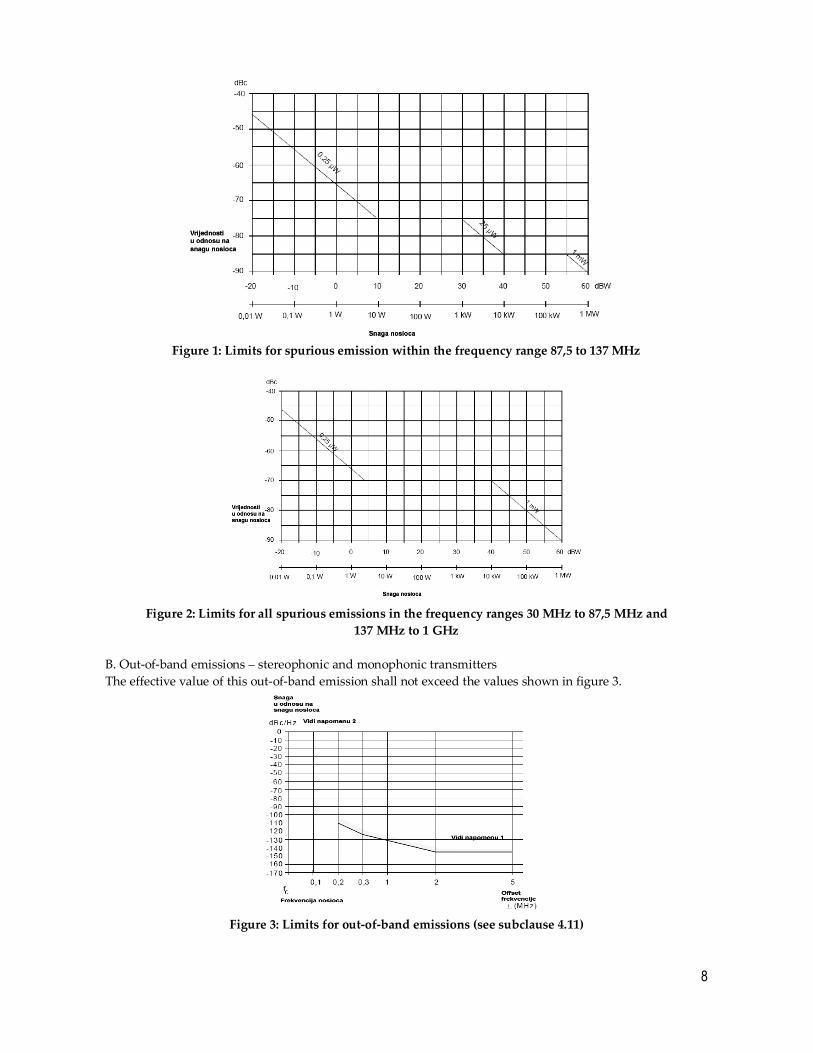
16. Spurious emissions
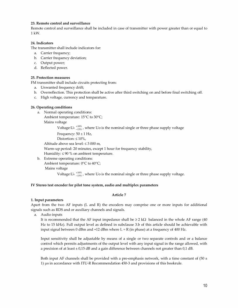
A. Spurious emissions shall not exceed:
a) the limits set out in figure 1 in the frequency range 87,5 MHz to 137 MHz;
b) the limits set out in figure 2 at any other frequency in the range 30 MHz to 1 GHz.
8
Figure 1: Limits for spurious emission within the frequency range 87,5 to 137 MHz
Figure 2: Limits for all spurious emissions in the frequency ranges 30 MHz to 87,5 MHz and
137 MHz to 1 GHz
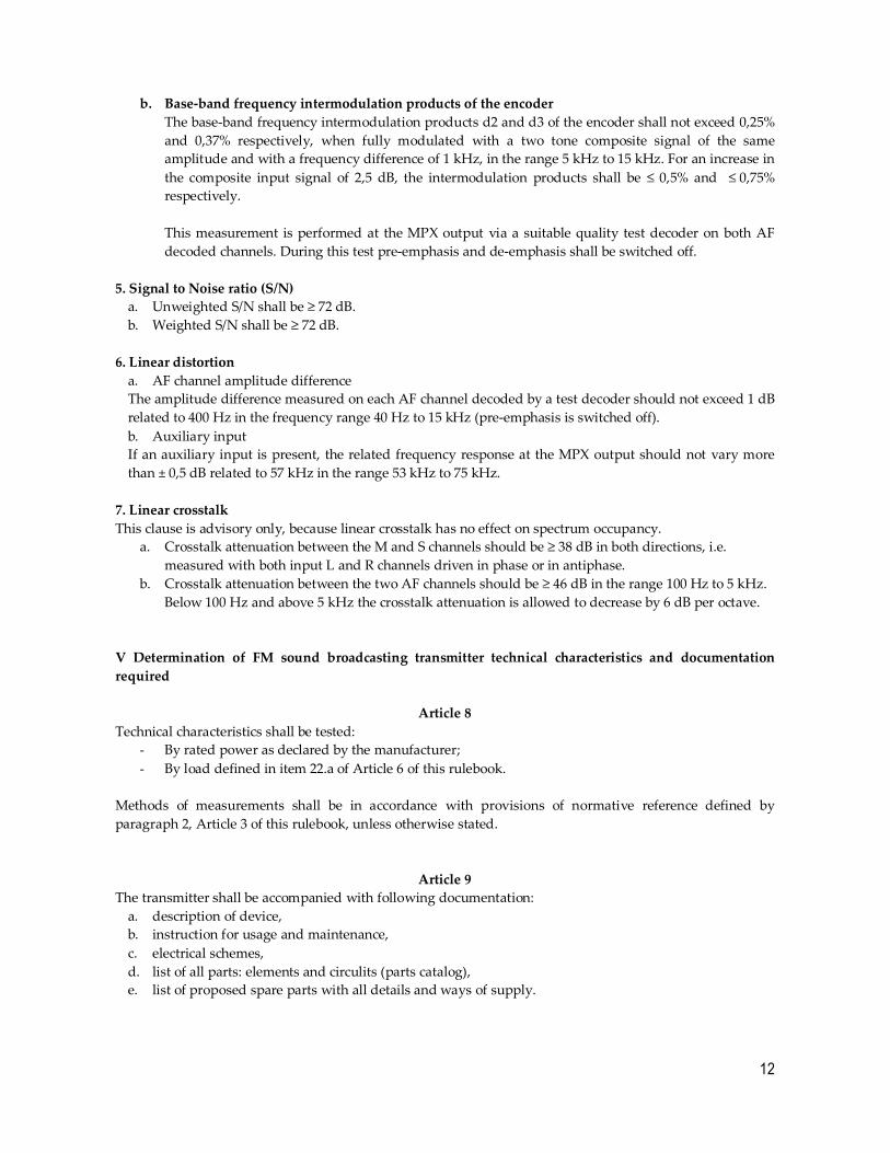
B. Out-of-band emissions – stereophonic and monophonic transmitters
The effective value of this out-of-band emission shall not exceed the values shown in figure 3.
Figure 3: Limits for out-of-band emissions (see subclause 4.11)

9
NOTE 1: The far-out of band emissions are influenced by transmitter output filter/combiner networks.
Measurements should be made with these in place, where necessary.
NOTE 2: The measurement bandwidth is 1 kHz; this curve is obtained by subtracting 30 dB from the
measured values.
17. Parasitic oscillation
Under determined operating conditions parasitic oscillation shall not occur.
18. Amplitude Modulation (AM)
a. Synchronous AM (AM due to FM) The permitted level of AM due to FM shall not exceed 2% for a peak deviation of ± 40 kHz at a modulation
frequency of 500 Hz.
b. Hum and noise (residual AM) The permitted level of residual AM in the absence of modulation shall not exceed 1% when measured in a
bandwidth of 20 Hz to 20 kHz (unweighted).
19. Test load characteristics For measurements detailed in table 1, the transmitter shall be required to operate into:
a. a precision load with a return loss of ≥ 26 dB in frequency range 87,5 MHz to 108 MHz and ≥ 16 dB
at all other frequencies up to 1 000 MHz;
b. a narrow band load with band pass characteristics as follows:
- return loss ≥ 26 dB over the range fc ± 100 kHz;
- return loss ≤ 0,5 dB outside the range fc ± 1 MHz;
where fc = transmitter carrier frequency;
c. a load with return loss of (16 ± 1) dB over the range fc ± 500 kHz for all phase angles.
Measurement Spurious emissions Out of band emissions
load a. test test
load b. test no test
load c. test test
Table 1: Test applicability table
20. Shielding radiation When transmitter is loaded by non-radiated test load, effective radiated power of shielding shall not be
greater than:
a. limiting power of spare components;
b. 1W on frequency of basic component in case of carrier power less than 10 kW and
c. 10W on frequency of basic component in case of carrier power greater than or equal to 10 kW.
21. Signal to Noise ratio Signal to noise ratio measured on 500 Hz, deviation of ± 40 kHz, with or without psophometric filter shall be
greater than 66 dB.
22. Measuring spots For the purpose of examination of signal path from modulator, pre-amplifier, actuating device nad output
device, transmitter shall incorporate measuring spots to be easilly accessed during operation periods.
On measuring spot loaded with 50 Ω resistance, output voltage shall be in range from 0.5 to 1 Veff. For
unloaded spot this voltage shall be less than double.
10
23. Remote control and surveillance Remote control and surveillance shall be included in case of transmitter with power greater than or equal to
1 kW.
24. Indicators The transmitter shall include indicators for:
a. Carrier frequency;
b. Carrier frequency deviation;
c. Output power;
d. Reflected power.
25. Protection measures FM transmitter shall include circuits protecting from:
a. Unwanted frequency drift;
b. Overreflection. This protection shall be active after third switching on and before final switching off.
c. High voltage, currency and temparature.
26. Operating conditions a. Normal operating conditions:
Ambient temperature: 15°C to 30°C;
Mains voltage
Voltage:U0 10%
15%
+
−, where Uo is the nominal single or three phase supply voltage
Frequency: 50 ± 1 Hz,
Distortion: ≤ 10%,
Altitude above sea level: ≤ 3 000 m,
Warm-up period: 20 minutes, except 1 hour for frequency stability,
Humidity: ≤ 90 % on ambient temperature.
b. Extreme operating conditions:
Ambient temperature: 0°C to 40°C;
Mains voltage
Voltage:U0 10%
15%
+
−, where Uo is the nominal single or three phase supply voltage.
IV Stereo test encoder for pilot tone system, audio and multiplex parameters
Article 7 1. Input parameters Apart from the two AF inputs (L and R) the encoders may comprise one or more inputs for additional
signals such as RDS and or auxiliary channels and signals.
a. Audio inputs
It is recommended that the AF input impedance shall be ≥ 2 kΩ balanced in the whole AF range (40
Hz to 15 kHz). Full output level as defined in subclause 3.b of this article should be achievable with
input signal between 0 dBm and +12 dBm where L = R (in phase) at a frequency of 400 Hz.
Input sensitivity shall be adjustable by means of a single or two separate controls and or a balance
control which permits adjustments of the output level with any input signal in the range allowed, with
a precision of at least ± 0,15 dB and a gain difference between channels not greater than 0,1 dB.
Both input AF channels shall be provided with a pre-emphasis network, with a time constant of (50 ±
1) µs in accordance with ITU-R Recommendation 450-3 and provisions of this bookrule.

11
Both AF channels shall be equipped with a 15 kHz low-pass filter. The attenuation of these filters shall
be at least 40 dB at 19 kHz, referred to 15 kHz. The stop-band attenuation above 19 kHz shall be ≥ 30
dB.
b. Auxiliary inputs
If an auxiliary input is provided its impedance should be ≥ 2 kΩ unbalanced in the range 53 kHz to 75
kHz.
If one or more auxiliary inputs are present, their input to output gain shall be adjustable (15% of full
output voltage is usually enough) to produce the required output in the required frequency band.
2. Pilot signal The pilot tone shall be 19 kHz ± 2 Hz.
If a pilot tone output is provided, the peak to peak output voltage shall be (1 ± 0,2) Volt into a load of ≥ 1 kW.
If an external pilot synchronising input facility is provided the peak to peak synchronising signal shall be in
the range 0,8 V to 1,2 V into a load of ≥ 1 kW.
3. Output MPX coded signal output shall not contain any DC offset.
The output level of the MPX coded signal for full deviation of a transmitter (i.e. ± 75 kHz) shall be adjustable
in the range required. The stereo encoder shall be capable of delivering its full performance as defined in this
bookrule, into the following loads:
- ≥ 300 W parallel with max capacitance of 5 000 pF;
- 75 W resistive load.
The pilot tone level shall be adjustable within the range from 8% to 10% of the output level.
At the reference output level for full modulation with L = R or L = -R, the sub-carrier level and the level of
all spurious frequencies higher than 53 kHz shall be in accordance with table 2.
Frequency Level
38 kHz (stereo sub-carrier)
53 - 55 kHz
55 - 59 kHz
59 - 200 kHz
200 kHz - 1 MHz
≤ - 42 dBr
≤ - 45 dBr
≤ - 57 dBr
≤ - 65 dBr
≤ - 70 dBr
Table 1 – Output levels of the stereo sub-carrier and spurious frequencies
The requirements in table 2 shall be met for any combination of audio inputs in the range 40 Hz to 15 kHz,
which produce 0 dBr MPX output level.
Usually the worst condition is approached with L = -R at maximum allowable level: in this case an applied
signal with a frequency fsi will produce two spectral lines at 38 kHz ± fsi whose reference level is -7 dBr
whilst the pilot tone at 19 kHz is -21 dBr.
4. Non linear distortion a. Harmonic distortion of the encoder
The harmonic distortion of the encoder shall be ≤ 0,5% for full deviation when modulated with an
AF input signal in the range 40 Hz to 15 kHz.
For an increase of the input signal of 2,5 dB the harmonic distortion shall be ≤ 1%.
12
b. Base-band frequency intermodulation products of the encoder The base-band frequency intermodulation products d2 and d3 of the encoder shall not exceed 0,25%
and 0,37% respectively, when fully modulated with a two tone composite signal of the same
amplitude and with a frequency difference of 1 kHz, in the range 5 kHz to 15 kHz. For an increase in
the composite input signal of 2,5 dB, the intermodulation products shall be ≤ 0,5% and ≤ 0,75%
respectively.
This measurement is performed at the MPX output via a suitable quality test decoder on both AF
decoded channels. During this test pre-emphasis and de-emphasis shall be switched off.
5. Signal to Noise ratio (S/N) a. Unweighted S/N shall be ≥ 72 dB.
b. Weighted S/N shall be ≥ 72 dB.
6. Linear distortion a. AF channel amplitude difference
The amplitude difference measured on each AF channel decoded by a test decoder should not exceed 1 dB
related to 400 Hz in the frequency range 40 Hz to 15 kHz (pre-emphasis is switched off).
b. Auxiliary input
If an auxiliary input is present, the related frequency response at the MPX output should not vary more
than ± 0,5 dB related to 57 kHz in the range 53 kHz to 75 kHz.
7. Linear crosstalk This clause is advisory only, because linear crosstalk has no effect on spectrum occupancy.
a. Crosstalk attenuation between the M and S channels should be ≥ 38 dB in both directions, i.e.
measured with both input L and R channels driven in phase or in antiphase.
b. Crosstalk attenuation between the two AF channels should be ≥ 46 dB in the range 100 Hz to 5 kHz.
Below 100 Hz and above 5 kHz the crosstalk attenuation is allowed to decrease by 6 dB per octave.
V Determination of FM sound broadcasting transmitter technical characteristics and documentation required
Article 8 Technical characteristics shall be tested:
- By rated power as declared by the manufacturer;
- By load defined in item 22.a of Article 6 of this rulebook.
Methods of measurements shall be in accordance with provisions of normative reference defined by
paragraph 2, Article 3 of this rulebook, unless otherwise stated.
Article 9 The transmitter shall be accompanied with following documentation:
a. description of device,
b. instruction for usage and maintenance,
c. electrical schemes,
d. list of all parts: elements and circulits (parts catalog),
e. list of proposed spare parts with all details and ways of supply.

13
VI Transitional and final provisions
Article 10
If radio stations from Article 1 are not in conformity with provisions stipulated from this rulebook, its
technical characteristics shall be adjusted in accordance with provisions of Law on Electronic
Communications.
Article 11
The day this rulebook enters into force, the Rulebook on the tecnical and exploatation conditions for the
frequency modulated emissions of the broadcasting stations ("Official Gazette RCG" No. 40/05, 42/06, 01/07,
16/07 and 45/07), shall cease to be valid.
Article 12 This rulebook shall enter into force within 8 days as of the day of publishing in the "Offical Gazette of
Montenegro".
Agency for Electronic Communications
and Postal Services
PRESIDENT OF THE COUNCIL
Dr Šaleta Đurović
14
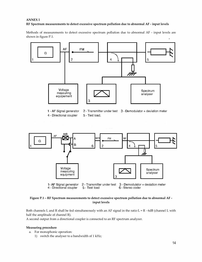
ANNEX I RF Spectrum measurements to detect excessive spectrum pollution due to abnormal AF - input levels Methods of measurements to detect excessive spectrum pollution due to abnormal AF - input levels are
shown in figure P.1.
Figure P.1 – RF Spectrum measurements to detect excessive spectrum pollution due to abnormal AF - input levels
Both channels L and R shall be fed simultaneously with an AF signal in the ratio L = R - 6dB (channel L with
half the amplitude of channel R).
A second output from a directional coupler is connected to an RF spectrum analyzer.
Measuring procedure
a. For monophonic operation:
1) switch the analyser to a bandwidth of 1 kHz;
15
2) adjust the spectrum analyser with the unmodulated FM carrier at the input to 0 dB;
3) modulate the transmitter with an AF signal;
4) adjust the output of the AF generator at 1 kHz to a level which corresponds to a frequency
deviation of ± 32 kHz i.e. 7,4 dB below maximum deviation;
5) increase the output level of the AF generator by 12 dB, resulting in a frequency deviation of
approximately ± 128 kHz for transmitters without a limiter;
6) tune the analyser to frequencies in the range fc ± Δf where 100 kHz ≤ Δf ≤ 500 kHz.
b. For stereophonic operation:
- adjust the output of the AF generator at 1 kHz to a level corresponding to a frequency deviation of
± 40 kHz including the pilot tone;
- for the remaining procedure, see the method used for monophonic operation.
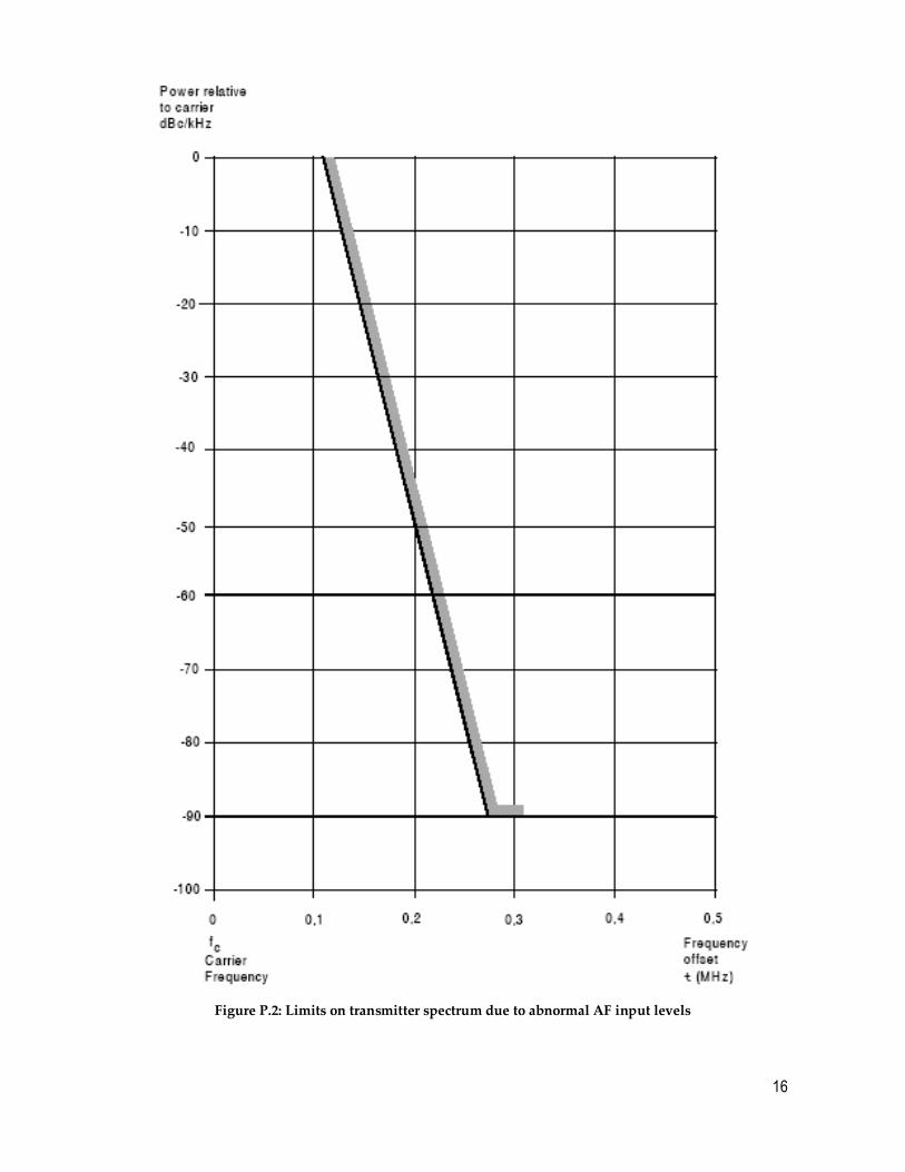
Presentation of the results The results shall be presented in the form of a graph in which relative levels in decibels are given as a
function of the frequency displacement from the carrier (Δf).
Limits on transmitter spectrum due to abnormal AF input levels are shown in figure P.2.
16
Figure P.2: Limits on transmitter spectrum due to abnormal AF input levels