rules and regulations for the construction and classification of spm systems - june · pdf...
TRANSCRIPT

INDIAN REGISTER OF SHIPPING
RULES AND REGULATIONS FOR THE CONSTRUCTION AND CLASSIFICATION OF SINGLE POINT MOORING SYSTEMS
June 2014
Publications of Indian Register of Shipping
1. Register Book – Available on CD updated quarterly 2. Rule Books
2.1 Rules and Regulations for the Construction and Classification of Steel Ships, July 2013 comprising of following six parts, which are further divided in chapters
Part 1 : Regulations Part 2 : Inspection and Testing of Materials Part 3 : General Hull Requirements Part 4 : Main and Auxiliary Machinery Part 5 : Special Ship Types (This part is published in two Volumes I & II) Part 6 : Fire Safety Requirements
Rules Change Notice No.1 – January, 2014 (Consolidated Rules January, 2014 available on IRS Website)
2.2 Rules and Regulations for the Construction and Classification of Inland Waterways Ships, January 1997, comprising of following five* parts which are further divided in chapters.
Part 1 : Regulations
Part 2 : Inspection and Testing of Materials (* This part is same as the Part 2 in 2.1 above)
Part 3 : General Hull Requirements Part 4 : Main and Auxiliary Machinery Part 5 : Special Ship Types (To be published)
2.3 Rules and Regulations for the Construction and Classification of Mobile Offshore Drilling Units, January 2013 (This supersedes, March 2006 edition).
2.4 Rules and Regulations for the Construction and Classification of High Speed Crafts and Light Crafts, July 2011. (Also available on CD)
Rules Change Notice No.1 – January, 2014 (Consolidated Rules January, 2014 available on IRS Website)
2.5 Rules and Regulations for the Construction and Classification of Naval Ships, January 2010, comprising of following six parts, which are further divided in chapters. (Only available on CD) Part 1 : General Regulations Part 2 : Manufacture, Testing and Certification of Materials Part 3 : General Hull Requirements Part 4 : General Requirements for Main and Auxiliary Machinery Part 5 : General Requirements for Electrical Installations and
Control Engineering Part 6 : Special Class Notations
2.6 Rules and Regulations for the Construction and Classification of Indian Coast
Guard Ships, July 2008, comprising of following six parts, which are further divided in chapters. (Only available on CD) Part 1 : General Regulations Part 2 : Manufacture, Testing and Certification of Materials Part 3 : General Hull Requirements Part 4 : General Requirements for Main and Auxiliary Machinery Part 5 : General Requirements for Electrical Installations and
Control Engineering Part 6 : Special Class Notations
2.7 Rules and Regulations for the Construction and Classification of SPM
Systems, June 2014. (Available on IRS Website) 3. Classification Notes
− Marine Gears - Calculation of load capacity of involute parallel axis spur and helical gears, January 1997.
− Cable trays/protective casing made of plastics materials, July 2003. − Type approval of mechanical joints used in piping, January 2014. − Type approval, installation and testing of water level detectors on bulk carriers and
single hold cargo ships other than bulk carriers, January 2013. − Guidelines for non-destructive examination of steel castings for marine application,
January 2005. − Guidelines for non-destructive examination of hull and machinery steel forgings,
January 2005. − Guidelines for approval / acceptance of alternative means of access to spaces in oil
tankers, bulk carriers, ore carriers and combination carriers, August 2006. − Approval scheme for the manufacturing process of normal and higher strength hull
structural steels, January, 2009. − Calculation of crankshafts for internal combustion engines, January, 2012. − Type testing procedure for crankcase explosion relief valves, February, 2008. − Type testing procedure for crankcase oil mist detection and alarm equipment,
February, 2008. − Type approval of electrical equipment used in control, protection, safety and internal
communication in marine environment, February, 2008. − Application of IRS Rules to Indian River Sea Vessels, August, 2013.
4. Type Approval Certification Schemes
− Type Approval Certification Scheme for Machinery Manufactured by Mass Production System, April 2000.
− Certification Scheme for Type Approval of Products, December 2012 5. Other Information - available on Request
− List of Type Approved Products − List of Approved Works − List of Approved Service Suppliers.
Indian Register of Shipping
Rules and Regulations for the Construction and Classification of SPM Systems
Contents
Chapter 1 General Chapter 2 Periodical Surveys Chapter 3 Materials and Welding Chapter 4 Design Loads Chapter 5 General Arrangement and Stability Chapter 6 Structures Chapter 7 Survey and Testing during Construction Chapter 8 Anchoring and Mooring Chapter 9 Systems and Equipment Chapter 10 Hazardous Areas Chapter 11 Safety Equipment

Rules and Regulations for the Construction and Classification of SPM Systems - 2014 Page 1 of 5
___________________________________________________________________________________
Indian Register of Shipping
Contents
Chapter 1 : General
Section 1 : General Information 1.1 Indian Register of Shipping 1.2 Survey reports 1.3 Fees 1.4 Register of Single Point Moorings 1.5 Liability 1.6 Access of Surveyor to SPM, shipyards or works 1.7 Compliance with statutory requirements Section 2 : Definitions Section 3 : Classification Regulations 3.1 General 3.2 Application of Rules 3.3 Scope of classification 3.4 Interpretations of the Rules 3.5 Character of classification 3.6 Class notations 3.7 Materials, components, equipment and machinery 3.8 Request for surveys 3.9 Repairs 3.10 Alterations
3.11 Date of build 3.12 Appeal from Surveyors' recommendations 3.13 Certificates 3.14 Suspension, withdrawal and deletion of class 3.15 Reclassification of Single Point Moorings Section 4 : Classification of Single Point Moorings Built under the Survey of Indian Register of Shipping 4.1 Classification of new constructions 4.2 Scope 4.3 Plans and design data 4.4 Operations & Maintenance Manual and information booklet 4.5 Records Section 5 Classification of Single Point Moorings not built under the Survey of Indian Register of Shipping 5.1 General procedure for classification of Single Point Moorings not built under survey of IRS 5.2 Plans and data to be furnished as required in 5.1.1
Page 2 of 5 Contents
___________________________________________________________________________________
Indian Register of Shipping
Chapter 2 : Periodical Surveys
Section 1 : General Requirements 1.1 General 1.2 Lay-up and Reactivation surveys 1.3 Surveys for damage 1.4 Alterations 1.5 Unscheduled surveys 1.6 Provision for hull surveys Section 2 : Annual Surveys 2.1 General
2.2 Survey requirements Section 3 : Docking Surveys or equivalent 3.1 General 3.2 Underwater-inspection in lieu of dry-docking survey Section 4 : Special Surveys 4.1 General 4.2 Special continuous surveys 4.3 Special Surveys
Chapter 3
Materials and Welding
Section 1 : Materials 1.1 Manufacture, Survey and Certification 1.2 Material Selection Section 2 : Corrosion Protection 2.1 Corrosion protection of structure
2.2 Corrosion protection of systems and equipment Section 3 : Welding 3.1 General 3.2 Welding and welded connections
Chapter 4
Design Loads
Section 1 : General 1.1 Application Section 2 : Gravity Loads, Pressure Heads & Functional Loads
Section 3 : Environmental Loads 3.1 General 3.2 Wind loads 3.3 Wave and current loads

Rules and Regulations for the Construction and Classification of SPM Systems - 2014 Page 3 of 5
___________________________________________________________________________________
Indian Register of Shipping
Chapter 5
General Arrangement and Stability
Section 1 : General Arrangement 1.1 General 1.2 Rotating Part 1.3 Protection 1.4 Access
Section 2 : Intact Stability Section 3 : Damaged Stability
Chapter 6
Structures
Section 1 : General Section 2 : Structural Design Principles 2.1 General Section 3 : Structural Strength 3.1 General 3.2 Structural Analysis 3.3 Buoy structure
3.4 Allowable stresses 3.5 Buckling of plates and stiffeners Section 4 : Scantlings of Local structural members 4.1 Plating 4.2 Stiffeners and beams 4.3 Girders
Chapter 7
Survey and Testing during Construction
Section 1 : General 1.1 General Section 2 : Testing of Tanks and Tight boundaries 2.1 General
2.2 Test Procedures Section 3 : Mooring System Section 4 : Cargo transfer, Control and Safety Systems
Page 4 of 5 Contents
___________________________________________________________________________________
Indian Register of Shipping
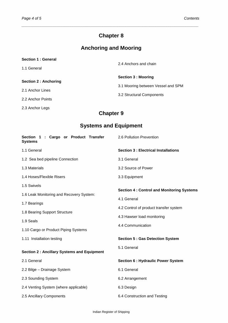
Chapter 8
Anchoring and Mooring Section 1 : General 1.1 General Section 2 : Anchoring 2.1 Anchor Lines 2.2 Anchor Points 2.3 Anchor Legs
2.4 Anchors and chain Section 3 : Mooring 3.1 Mooring between Vessel and SPM 3.2 Structural Components
Chapter 9
Systems and Equipment Section 1 : Cargo or Product Transfer Systems 1.1 General 1.2 Sea bed pipeline Connection 1.3 Materials 1.4 Hoses/Flexible Risers 1.5 Swivels 1.6 Leak Monitoring and Recovery System: 1.7 Bearings 1.8 Bearing Support Structure 1.9 Seals 1.10 Cargo or Product Piping Systems 1.11 Installation testing Section 2 : Ancillary Systems and Equipment 2.1 General 2.2 Bilge – Drainage System 2.3 Sounding System 2.4 Venting System (where applicable) 2.5 Ancillary Components
2.6 Pollution Prevention Section 3 : Electrical Installations 3.1 General 3.2 Source of Power 3.3 Equipment Section 4 : Control and Monitoring Systems 4.1 General 4.2 Control of product transfer system 4.3 Hawser load monitoring 4.4 Communication Section 5 : Gas Detection System 5.1 General Section 6 : Hydraulic Power System 6.1 General 6.2 Arrangement 6.3 Design 6.4 Construction and Testing
Rules and Regulations for the Construction and Classification of SPM Systems - 2014 Page 5 of 5
___________________________________________________________________________________
Indian Register of Shipping
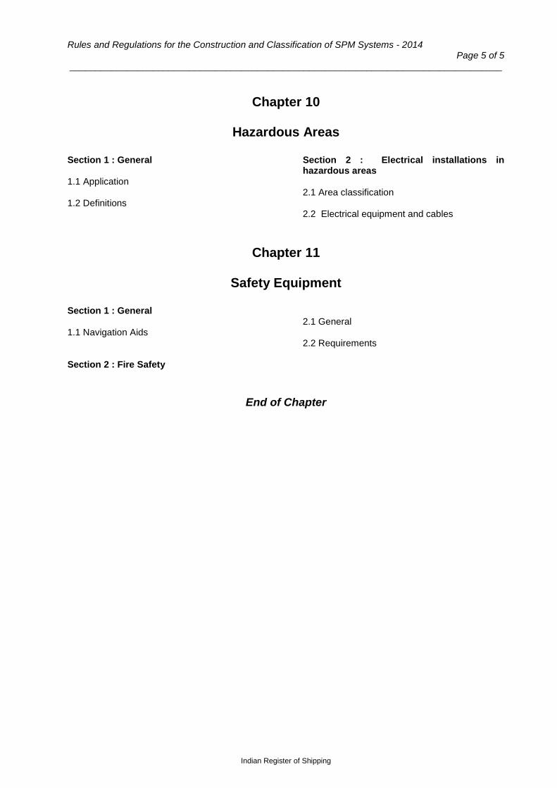
Chapter 10
Hazardous Areas
Section 1 : General 1.1 Application 1.2 Definitions
Section 2 : Electrical installations in hazardous areas 2.1 Area classification 2.2 Electrical equipment and cables
Chapter 11
Safety Equipment
Section 1 : General 1.1 Navigation Aids Section 2 : Fire Safety
2.1 General 2.2 Requirements
End of Chapter
Rules and Regulations for the Construction and Classification of SPM Systems - 2014 Page 1 of 9
_________________________________________________________________________________
Indian Register of Shipping
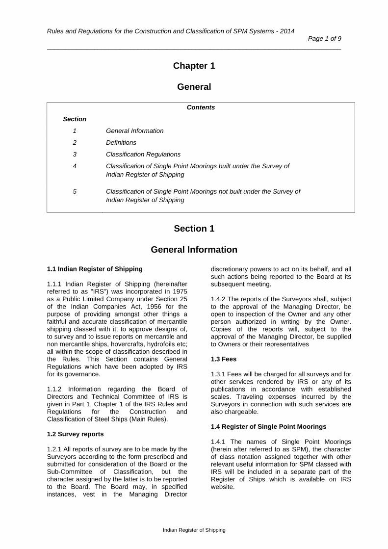
Chapter 1
General
Contents
Section
1 General Information
2 Definitions
3 Classification Regulations
4 Classification of Single Point Moorings built under the Survey of Indian Register of Shipping
5 Classification of Single Point Moorings not built under the Survey of Indian Register of Shipping
Section 1
General Information
1.1 Indian Register of Shipping 1.1.1 Indian Register of Shipping (hereinafter referred to as "IRS") was incorporated in 1975 as a Public Limited Company under Section 25 of the Indian Companies Act, 1956 for the purpose of providing amongst other things a faithful and accurate classification of mercantile shipping classed with it, to approve designs of, to survey and to issue reports on mercantile and non mercantile ships, hovercrafts, hydrofoils etc; all within the scope of classification described in the Rules. This Section contains General Regulations which have been adopted by IRS for its governance. 1.1.2 Information regarding the Board of Directors and Technical Committee of IRS is given in Part 1, Chapter 1 of the IRS Rules and Regulations for the Construction and Classification of Steel Ships (Main Rules). 1.2 Survey reports 1.2.1 All reports of survey are to be made by the Surveyors according to the form prescribed and submitted for consideration of the Board or the Sub-Committee of Classification, but the character assigned by the latter is to be reported to the Board. The Board may, in specified instances, vest in the Managing Director
discretionary powers to act on its behalf, and all such actions being reported to the Board at its subsequent meeting. 1.4.2 The reports of the Surveyors shall, subject to the approval of the Managing Director, be open to inspection of the Owner and any other person authorized in writing by the Owner. Copies of the reports will, subject to the approval of the Managing Director, be supplied to Owners or their representatives 1.3 Fees 1.3.1 Fees will be charged for all surveys and for other services rendered by IRS or any of its publications in accordance with established scales. Traveling expenses incurred by the Surveyors in connection with such services are also chargeable. 1.4 Register of Single Point Moorings 1.4.1 The names of Single Point Moorings (herein after referred to as SPM), the character of class notation assigned together with other relevant useful information for SPM classed with IRS will be included in a separate part of the Register of Ships which is available on IRS website.

Chapter 1 General
Page 2 of 9
Indian Register of Shipping
1.5 Liability 1.5.1 Whilst Indian Register of Shipping (hereinafter referred to as IRS) and its Board/Committees use their best endeavours to ensure that the functions of IRS are properly carried out, in providing services, information or advice, neither IRS nor any of its servants or agents warrants the accuracy of any information or advice supplied. Except as set out herein, neither IRS nor any of its servants or agents (on behalf of each of whom IRS has agreed this clause) shall be liable for any loss damage or expense whatever sustained by any person due to any act or omission or error of whatsoever nature and howsoever caused of IRS, its servants or agents or due to any inaccuracy of whatsoever nature and howsoever caused in any information or advice given in any way whatsoever by or on behalf of IRS, even if held to amount to a breach of warranty. Nevertheless, if any person uses services of IRS, or relies on any information or advice given by or on behalf of IRS and suffers loss damage or expenses thereby which is proved to have been due to any negligent act omission or error of IRS its servants or agents or any negligent inaccuracy in information or advice given by or on behalf of IRS then IRS will pay compensation
to such person for his proved loss up to but not exceeding the amount of the fee charged by IRS for that particular service, information or advice. 1.5.2 Any notice of claim for loss, damage or expense as referred to in 1.6.1 shall be made in writing to IRS Head Office within six months of the date when the service, information or advice was first provided, failing which all the rights to any such claim shall be forfeited and IRS shall be relieved and discharged from all liabilities. 1.6 Access of Surveyor to SPM, shipyards or works 1.6.1 The Surveyors are to be given free access to SPM classed with IRS as well as to shipyards/fabrication facility, works, etc. so as to perform their duties, and are to receive adequate assistance for this purpose. 1.7 Compliance with statutory requirements 1.7.1 Consideration should be given to any relevant requirements of the National Authority of the country in which the SPM is to be registered.
Section 2
Definitions
The definitions given below, in alphabetical order, shall apply for the purpose of these Rules.
1) Anchor Leg means the mooring element connecting the single point mooring structure to the seabed at the anchor point, and is essential for station keeping of the system.
2) Buoyancy Element means a buoyancy member provided to support the weight of mooring equipment or risers, and designed to resist differential pressure from submergence and internal pressure.
3) Cargo means same as Product as
defined in para 10.
4) Hawser is the mooring line between SPM structure and moored vessel.
5) Hose is a conduit designed to convey
fluids between supply and delivery points with significant relative movement
and able to tolerate large deflections. Typically, a hose is comprised of a string or series of short hose segments joined together at flanged ends.
6) Floating Hose is a hose or hose string
located between the SPM structure and the moored vessel for the purpose of conveying fluid. When not connected to a moored vessel it remains connected to the SPM structure and floats on the sea water surface.
7) Underbuoy Hose is a hose or hose
string located between the SPM structure and the pipe line end manifold (PLEM) for the purpose of conveying fluids.
8) Main Bearing is the bearing which
supports the load from the mooring and hawser and provides a mechanism for the moored vessel to rotate or weathervane about the mooring structure.

Rules and Regulations for the Construction and Classification of SPM Systems - 2014 Page 3 of 9
_________________________________________________________________________________
Indian Register of Shipping
9) PLEM (Pipeline end manifold) is an
installation on the sea bed which connects the sub-sea pipelines to the riser/ underbuoy hose. Subsea valves form part of the PLEM, which are usually controlled hydraulically with the help of umbilical.
10) Product is defined as any fluid transferred between the moored vessel and the pipeline end manifold (PLEM) such as crude oil, petroleum product, petroleum gas, slurry, and bunkers.
11) Product Swivel is a mechanism which
provides for passage of cargo or product while allowing the main structure to weathervane freely with respect to the fixed or anchored structure.
12) Flexible Riser is a conduit designed to
convey fluids between supply and delivery points with or without significant relative movement and able to tolerate large deflections. A flexible riser is usually comprised of one continuous length, used for relatively greater water
depths and constructed to be used totally submerged.
13) Single Point Mooring (SPM) is a
system which permits a vessel to weathervane while the vessel is moored to a fixed or floating structure anchored to the seabed by a rigid or an articulated structural system or by catenary spread mooring. Catenary Anchor Leg Mooring (CALM) is an example of a floating SPM which uses catenary spread mooring.
14) Swing Circle is the area swept by the
moored vessel as it revolves about the mooring point.
15) Turret mooring is a type of single point
mooring where the slewing function which allows weathervaning, forms an integral part of the unit. The buoy body with deckhouse rotates around a central turret moored to the seabed.
16) Wheel and Rail Buoy is a type of SPM
buoy with a rotating bogey platform on wheels running on rails, allowing the tanker to weather wave around the buoy.
Section 3
Classification Regulations 3.1 General 3.1.1 When a SPM is assigned a specific Character of Class by Indian Register of Shipping, it implies that IRS is satisfied that the said SPM meets, for this particular class, with these Rules and Regulations or requirements equivalent thereto. The SPM will continue to be classed with IRS so long as it is found, upon examination at the prescribed annual and periodical surveys, to be maintained in a fit and efficient condition and in accordance with the Periodical Survey requirements of these Rules. 3.1.2 The classification of a Single Point Mooring with IRS does not exempt the owners from compliance with any additional and/or more stringent requirements issued by the Administration and/or local port authority. 3.2 Application of Rules 3.2.1 These rules apply to unmanned floating Single Point Mooring systems of the Catenary Anchored Leg Mooring (CALM) type as defined
in Sec 2 and are generally intended for temporary mooring of vessels. Classification is valid only for operation in the specified area which will be mentioned in the certificate. 3.2.2 The rules are applicable to those features of the system that are permanent in nature and can be verified by plan review, calculation, physical survey and other appropriate means. Any statement in the rules regarding other features is to be considered as guidance to designer, builder or owner. 3.2.4 These rules apply to conventional SPM designs which provide temporary offshore mooring to a variety of vessels by means of a hawser from the buoy. Fluid transfer between the vessel and a sea floor pipeline is performed by an underbuoy hose or riser, and a hose between the buoy and the vessel. 3.2.3 Unless directed otherwise by IRS, no new Regulations or amendments to the Rules relating to the character of classification or class

Chapter 1 General
Page 4 of 9
Indian Register of Shipping
notation is to be applied to the existing Single Point Moorings. 3.2.4 Unless directed otherwise by IRS, no new Rules and Regulations or amendments to the existing Rules & Regulations become applicable within 6 months after the date of issue nor after the approval of main structural plans. Where it is proposed to use existing previously approved plans for a new contract, written application is to be made to IRS. 3.3 Scope of classification 3.3.1 Classification covers the following aspects, equipment, components and systems of the SPM:
a) Structure of buoy, materials and welding
b) stability and watertight integrity c) main bearing, rotating arm or turret d) Anchoring and mooring systems e) Auxiliary machinery, piping and
electrical installations f) Fluid transfer systems and equipment
including swivel, underbuoy and floating hoses
g) Instrumentation and control systems, telemetry
h) Fire safety i) Pipeline end manifold (PLEM), (also see
3.6.4). 3.4 Interpretations of the Rules 3.4.1 The correct interpretation of the requirements contained in the Rules and other Regulations is the sole responsibility and at the sole discretion of IRS. 3.5 Character of classification 3.5.1 The following Characters and symbols are assigned by IRS to indicate classification of Steel Single Point Moorings. 3.5.2 Character SU assigned to an SPM to indicates that, the SPM and related components and systems meets the Rule requirements for assignment of this Character of Class. 3.5.3 The distinguishing mark inserted before Characters of Class or Class Notation(s) is assigned to new SPM constructed under special survey of IRS in compliance with the Rules to the satisfaction of IRS. 3.6 Class notations 3.6.1 When requested by an Owner and agreed to by IRS or when considered necessary by IRS,
class notation(s) as detailed below will be appended to the character of classification. 3.6.2 Notation ‘Single Point Mooring’ will be assigned to SPM systems complying with the requirements of these rules. Type Notation ‘CALM’ will be assigned to SPMs of the catenary anchored leg mooring type for which these rules apply 3.6.3 Operating area Notation: An appropriate notation will be appended to the class notation to specify the operating area of the SPM. 3.6.4 When requested by owner and agreed upon by IRS, the pipeline end manifold within the SPM system may be excluded from the scope of classification. The process used for controlling the flow of the fluid between subsea pipeline and moored vessel is to be fully described in the documentation submitted to IRS when requesting the exemption. A suitable change in classification notation will be made to represent the exemption. It will be the owner’s responsibility to verify that this exclusion is acceptable to the governmental authority having jurisdiction over the SPM. 3.7 Materials, components, equipment and machinery 3.7.1 The materials used in the construction of SPM, or in the repair of SPM already classed, are to be of good quality and free from defects and are to be tested in accordance with the relevant Rules. The steel is to be manufactured by an approved process at works recognized by IRS. Alternatively, tests to the satisfaction of IRS will be required to demonstrate the suitability of the steel. Consideration may be given by IRS to accept the works approved by IACS member societies with whom IRS currently has co-operation agreements for this purpose. 3.7.2 Certification of materials, components, equipment and machinery is carried out on the basis of the following, considering IRS and /or IMO requirements, as applicable:
a) Type approval carried out by IRS b) Unit certification by IRS
Mutual recognition of certificates, if type approved by an IACS member society or European Union recognized organization based on commonly agreed design requirements between IRS and the recognized organization.
Rules and Regulations for the Construction and Classification of SPM Systems - 2014 Page 5 of 9
_________________________________________________________________________________
Indian Register of Shipping
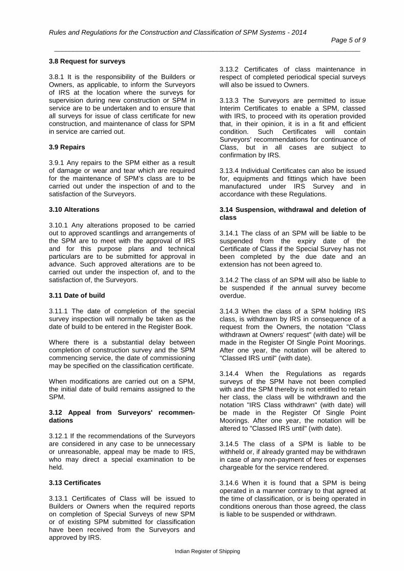
3.8 Request for surveys 3.8.1 It is the responsibility of the Builders or Owners, as applicable, to inform the Surveyors of IRS at the location where the surveys for supervision during new construction or SPM in service are to be undertaken and to ensure that all surveys for issue of class certificate for new construction, and maintenance of class for SPM in service are carried out. 3.9 Repairs 3.9.1 Any repairs to the SPM either as a result of damage or wear and tear which are required for the maintenance of SPM’s class are to be carried out under the inspection of and to the satisfaction of the Surveyors. 3.10 Alterations 3.10.1 Any alterations proposed to be carried out to approved scantlings and arrangements of the SPM are to meet with the approval of IRS and for this purpose plans and technical particulars are to be submitted for approval in advance. Such approved alterations are to be carried out under the inspection of, and to the satisfaction of, the Surveyors. 3.11 Date of build 3.11.1 The date of completion of the special survey inspection will normally be taken as the date of build to be entered in the Register Book. Where there is a substantial delay between completion of construction survey and the SPM commencing service, the date of commissioning may be specified on the classification certificate. When modifications are carried out on a SPM, the initial date of build remains assigned to the SPM. 3.12 Appeal from Surveyors' recommen-dations 3.12.1 If the recommendations of the Surveyors are considered in any case to be unnecessary or unreasonable, appeal may be made to IRS, who may direct a special examination to be held. 3.13 Certificates 3.13.1 Certificates of Class will be issued to Builders or Owners when the required reports on completion of Special Surveys of new SPM or of existing SPM submitted for classification have been received from the Surveyors and approved by IRS.
3.13.2 Certificates of class maintenance in respect of completed periodical special surveys will also be issued to Owners. 3.13.3 The Surveyors are permitted to issue Interim Certificates to enable a SPM, classed with IRS, to proceed with its operation provided that, in their opinion, it is in a fit and efficient condition. Such Certificates will contain Surveyors' recommendations for continuance of Class, but in all cases are subject to confirmation by IRS. 3.13.4 Individual Certificates can also be issued for, equipments and fittings which have been manufactured under IRS Survey and in accordance with these Regulations. 3.14 Suspension, withdrawal and deletion of class 3.14.1 The class of an SPM will be liable to be suspended from the expiry date of the Certificate of Class if the Special Survey has not been completed by the due date and an extension has not been agreed to. 3.14.2 The class of an SPM will also be liable to be suspended if the annual survey become overdue. 3.14.3 When the class of a SPM holding IRS class, is withdrawn by IRS in consequence of a request from the Owners, the notation "Class withdrawn at Owners' request" (with date) will be made in the Register Of Single Point Moorings. After one year, the notation will be altered to "Classed IRS until" (with date). 3.14.4 When the Regulations as regards surveys of the SPM have not been complied with and the SPM thereby is not entitled to retain her class, the class will be withdrawn and the notation "IRS Class withdrawn" (with date) will be made in the Register Of Single Point Moorings. After one year, the notation will be altered to "Classed IRS until" (with date). 3.14.5 The class of a SPM is liable to be withheld or, if already granted may be withdrawn in case of any non-payment of fees or expenses chargeable for the service rendered. 3.14.6 When it is found that a SPM is being operated in a manner contrary to that agreed at the time of classification, or is being operated in conditions onerous than those agreed, the class is liable to be suspended or withdrawn.

Chapter 1 General
Page 6 of 9
Indian Register of Shipping
3.14.7 The class of a SPM which has maintained class would be deleted on receipt of information that it has been scrapped or ceases to exist, and an appropriate entry would be made in the Register of Single Point Moorings. 3.14.8 In cases where the class has been suspended by IRS and it becomes apparent that the owners are not interested in maintaining IRS class, the notation will be amended to withdrawn status. 3.15 Reclassification of Single Point Moorings 3.15.1 When Owners request for reclassification of a SPM for which the class previously
assigned has been withdrawn, IRS will require a Special Survey for Reclassification to be held by the IRS Surveyors. The extent of the survey will depend upon the age of the SPM and the circumstances of each case. 3.15.2 If the SPM is found or placed in good and efficient condition in accordance with the requirements of the Rules and Regulations at the Special Survey for Reclassification, IRS may decide to reinstate her original class or assign such other class as considered appropriate. 3.15.3 The date of reclassification will appear in the Register of Single Point Moorings.
Section 4
Classification of Single Point Moorings Built under the Survey of
Indian Register of Shipping 4.1 Classification of new constructions 4.1.1 The request for classification of new constructions is to be submitted to IRS by the shipyard or shipowner in the form provided by IRS. The request is to include complete details regarding class notation and statutory certificates required, where applicable. 4.1.2 Where orders for major machinery and equipment are placed on manufacturer or suppliers, IRS will have to be informed. Responsibility for compliance with IRS Rules and Regulations shall be with the manufacturers/suppliers. 4.1.3 Plans and particulars as specified in the Rules will have to be submitted to IRS in triplicate sufficiently in advance of commencement of construction. One copy with stamp of approval will be returned. Any deviation from approved drawings will require to be approved by IRS prior to execution of work. IRS reserves the right to request for additional plans, information or particulars to be submitted. Approval of plans and calculations by IRS does not relieve the Builders of their responsibility for the design, construction and installation of the various parts, nor does it absolve the Builders from their duty of carrying out any alterations or additions to the various parts on board deemed necessary by IRS during construction or installation on board or trials.
4.1.4 IRS will assess the production facilities and procedures of the shipyard and other manufacturers as to whether they meet the requirements of the construction Rules. 4.1.5 During construction of a SPM, IRS will ensure by surveys that parts of SPM requiring approval have been constructed in compliance with approved drawings, all required tests and trials are performed satisfactorily, workmanship is in compliance with current engineering practices and welded parts are produced by qualified welders. 4.1.6 The SPM will be subjected to operational trials in the presence of IRS Surveyor. 4.1.7 On completion of the construction and trials of the SPM, copies of as fitted plans showing the SPM as built, essential certificates and records, operating manual etc. are to be submitted by the Builder generally prior to issuance of the Interim Certificate of Class. 4.2 Scope 4.2.1 The items listed in 3.3.1 above, where applicable, are covered by these requirements and are subject to approval by IRS : 4.3 Plans and design data 4.3.1 Plans showing the scantlings, arrangements and details of the main parts of the structure of each unit are to be submitted for approval before construction. These plans are to

Rules and Regulations for the Construction and Classification of SPM Systems - 2014 Page 7 of 9
_________________________________________________________________________________
Indian Register of Shipping
indicate types and grades of materials, joint details and welding, or other methods of connection. The following plans are to be included, as applicable:
- General arrangement
- An arrangement plan of watertight compartments including the location, type and disposition of watertight and weathertight closures
- Structural arrangement showing shell
plating, framing, bulkheads, flats, main and bracing members, joint details, as applicable
- Details of watertight doors and hatches
- Fendering and access ladders
- Welding details and procedures
- Coatings and corrosion control
arrangements
- Type, location and amount of permanent ballast, if any
- Bilge, sounding and venting
arrangements
- Hazardous areas
- Electrical system one line diagrams
- Location of fire safety equipment
- Mooring arrangement
- Mooring components including anchor legs, associated hardware, hawser(s), and hawser load-deflection characteristics
- Foundations for mooring components,
equipment, etc. with attachments to hull structure
- Anchoring system indicating the size of
anchor, holding capacity of piles, pile sizes, structures and capacity and attachment of mooring lines to the pile.
- Pipe Line End Manifold (PLEM) as
applicable
- SPM main bearing
- Cargo or product swivel including swivel driving mechanism, swivel bearings, and electrical swivel details
- Product or cargo system piping
schematic drawing with bill of materials
- Design data of equipment, piping and related components including minimum and maximum design pressure and temperature
- Ancillary piping systems schematic
drawings with bills of material
- Floating and underbuoy hoses/flexible risers and attachments
- Telemetry/Control system
- Navigation aids
- Methods and locations for non-
destructive testing (NDT)
- Plans for conducting underwater inspections in lieu of drydocking
- Test and inspection plan for all major
load carrying or pressure retaining components including cargo or product swivel, electrical swivel, bearings.
- Test Procedures
4.3.2 Site Chart and Site condition report 4.3.2.1 A site chart of the mooring area is to be submitted for information which shows the following: - Depth soundings in the swing circle, maneuvering area and approach channels - potential navigation hazards and existing and planned navigation aids, - location and water depth of the mooring base or pipe line end manifold (PLEM), and each anchor point, - The route of the submarine pipeline and of all other pipelines and cables. 4.3.2.2 The following environmental data are to be submitted for information: - Environmental conditions of wind, waves, current, tide, visibility, temperature and ice - bottom soil conditions

Chapter 1 General
Page 8 of 9
Indian Register of Shipping
4.3.4 Design loads from model tests 4.3.4.1 Model tests may be used to determine the design loads or to verify the calculated design loads. In such cases, description of model test facilities and procedures, analysis and a summary of the results are to be submitted. It is recommended that IRS is consulted regarding model testing.. 4.3.5 Design Calculations 4.3.5.1 The following design calculations/ analysis report are to be submitted, as applicable: a) Structural design in accordance with Ch 6. b) Stability calculations in accordance with Ch 5. c) Mooring and anchoring including fatigue life of anchor chain in accordance with Ch 8. d) Piping in accordance with Ch 9. e) Calculations for all pressure retaining and load bearing components in accordance with Ch 9. f) Swivel static and dynamic analysis in accordance with Ch 9. g) Single pressure calculations of product transfer system in accordance with Ch.9. h) Dynamic analysis of underbuoy hoses/flexible risers in accordance with Ch.9. i) Interference analysis of underbuoy hoses, umbilical of anchor lines in accordance with Ch.9. j) Fatigue life assessment of underbuoy hoses / flexible risers in accordance with Ch.9. 4.4 Operations & Maintenance Manual and information booklet 4.4.1 An operations & maintenance manual and information booklet is to be submitted for the SPM. 4.4.2 The manual is to include the following information. a) Site chart as described in 4.3.2 b) The particulars of the maximum size moored vessel considered in the design of SPM , including displacement, length, draft and distance from bow to manifold..
c) Environmental design criteria with various sizes of vessels, including the operating wind, wave, current and tides. d) Design cargo transfer criteria, including type of cargo and design maximum working pressure, temperature, flow rate, and minimum valve closing times including the vessel's manifold valves. e) Plans showing the general arrangement of the single point mooring components and details of those components required to be handled during operation or inspected during maintenance, including details of access to these components. f) Description of navigation aids and safety features. g) Recommended procedure for the mooring and disconnecting a vessel at the SPM h) Recommended procedure for connecting and disconnecting floating hose to a tanker's manifold. i) Recommended maintenance schedule and procedures for the SPM facilities, including a check list of items recommended for periodic inspection. Where applicable, procedures for adjusting anchor leg tension, removal and reinstallation of hoses, inspection of flexible risers, adjustment of buoyancy tanks, and replacement of seals in the cargo swivel are to be included. j) Recommended cargo system pressure testing. 4.4.3 The Operations & Maintenance Manual and information booklet is to be submitted for review by IRS to verify consistency with the design information and limitations considered in the SPM's classification. Any additional information required by coastal or flag Administrations are to be included in the operations and maintenance manual. 4.4.4 The water depth for operation is to take into account the following factors:
a) Vessel's dimensions and other relevant characteristics.
b) Wave height, wave period, and compass direction with respect to the vessel.
c) The prevailing wind and astronomical tides.
d) The expected vessel's heaving, rolling and pitching and adequate vessel under keel clearance.

Rules and Regulations for the Construction and Classification of SPM Systems - 2014 Page 9 of 9
_________________________________________________________________________________
Indian Register of Shipping
4.5 Records 4.5.1 The following information or records are to be maintained : .1 survey record in accordance with Ch.2; .2 inspection and maintenance records
.3 light weight data alterations log .4 testing records and equipment changes for anchors and related equipment as per Ch 8; .5 maintenance, inspection and testing records relating to fire-fighting equipment as per Ch 11.
Section 5
Classification of Single Point Moorings not built under the Survey of
Indian Register of Shipping 5.1 General procedure for classification of Single Point Moorings not built under survey of IRS 5.1.1 Plans of SPM in duplicate are to be submitted for approval. It is preferable to have the plans approved before the classification survey is commenced. 5.1.2 Full special classification surveys would require to be carried out by IRS Surveyors in order to satisfy themselves regarding the workmanship and to verify the approved scantlings and arrangements. The scope of these surveys may, however, be modified in the case of SPMs built under the Special Survey and holding valid certificates of class of established classification societies, if prior to commencement of survey by IRS, documentary evidence of all classification surveys held by the other society subsequent to last special survey carried out by them could be produced. In such cases, a special survey notation will not be assigned in conjunction with the classification survey. The next special survey therefore would become due five years from the special survey held by the other society and not five years from classification with IRS.
In cases of transfer of class from another society to single class of IRS, the interim certificate of class or any other documents enabling the Single Point Mooring to operate can be issued only after all overdue surveys and recommendations or conditions of class issued by the previous society are satisfactorily completed. 5.1.3 For SPM not built under survey of IRS but subsequently taken in class with the above procedure, the mark signifying the survey during construction will be omitted. 5.1.4 Once a SPM has been taken into IRS class, periodical surveys are subsequently to be held as per these rules. 5.2 Plans and data to be furnished as required in 5.1.1 5.2.1 Plans of hull and equipment showing the main scantlings and arrangements of the actual SPM and any proposed alterations are to be submitted for approval. These are to normally comprise of the plans listed in 4.3:
End Of Chapter

Rules and Regulations for the Construction and Classification of SPM Systems - 2014 Page 1 of 6
___________________________________________________________________________________
Indian Register of Shipping
Chapter 2
Periodical Surveys
Contents
Section
1 General Requirements
2 Annual Surveys
3 Docking Surveys
4 Special Surveys
Section 1
General Requirements 1.1 General 1.1.1 All SPMs are to be subjected to periodical surveys for the purpose of maintenance of class. Survey notations and Survey intervals are given in Table 1.1.1. 1.1.2 Definitions: a) Ballast Tank is a tank which is used
primarily for salt water ballast. b) Suspect Areas are locations considered by
the Surveyor to be prone to rapid wastage. c) Critical areas are locations which have been
identified from calculations to require monitoring or from the service history of the subject unit or sister units (if available) to be sensitive to cracking, buckling or corrosion which would impair the structural integrity of the unit.
d) Anniversary date means the day and month of each year corresponding to the expiry date of the classification certificate
1.2 Lay-up and Reactivation surveys 1.2.1 When a SPM is laid up and IRS is so informed, the periodical surveys required by 1.1.1, except annual surveys, may be postponed at the discretion of IRS depending upon the vessel’s lay-up location and the maintenance and preservative measures taken during the lay-up. 1.2.2 In the case of SPM which have been out of service for an extended period of six (6) months or more, the requirements for reactivation surveys will be specially considered in each case with due regard given to the status of surveys at the time of the commencement of the lay-up period, the length of the period, and conditions under which the unit had been maintained during that period.

Chapter 2 Periodical Surveys
Page 2 of 6
Indian Register of Shipping
Table 1.1.1 : Periodical survey intervals
(Any specific requirements of the flag administration or local authority are also to be complied with)
Survey Main class survey notation Survey interval in years
Special Survey SS 5
Continuous Survey CS 5
Annual Survey AS 11
Docking Survey or equivalent DS 52 Notes: 1. Survey may be carried out within 3 months on either side of the due date. 2. Proposals for alternative means for providing underwater inspections equivalent to drydocking
survey would be considered by IRS as detailed in Section 3. The number of underwater inspections equivalent to dry docking that may be accepted would depend on the design life, corrosion margins and coating life of the SPM.
1.3 Surveys for damage 1.3.1 It is the responsibility of the owner/ operator of the SPM to report to IRS without delay any damage, defect or breakdown, which could invalidate the conditions for which a classification has been assigned so that it may be examined at the earliest opportunity by IRS Surveyor(s). All repairs found necessary by the Surveyor are to be carried out to his satisfaction. 1.4 Alterations 1.4.1 No alterations which may affect classifi-cation are to be made to the hull or machinery of a classed unit unless plans of proposed alterations are submitted and approved by IRS before the work of alterations is commenced. Such work is to be carried out in accordance with approved plans and tested on completion as required by the Rules and to the satisfaction of the Surveyor(s). 1.5 Unscheduled surveys 1.5.1 In the event that IRS has reason to believe that its Rules and Regulations are not being complied with, IRS reserves the right to perform unscheduled surveys of the hull or machinery.
1.6 Provision for hull surveys 1.6.1 The Surveyors are to be provided with necessary facilities for a safe execution of survey. 1.6.2 Tanks and spaces are to be safe for access, i.e. gas freed, ventilated, etc. Tanks and spaces are to be reasonably clean and free from water, scale, dirt, oil residues, etc. to reveal significant corrosion, deformation, fractures, damages and other structural deterioration. 1.6.3 Adequate illumination is to be provided to reveal significant corrosion, deformation, fractures, damages or other structural deterioration. 1.6.4 Means are to be provided to enable the Surveyor to examine the structure in a safe and practical way. 1.6.5 Thickness measurement is normally to be carried out by means of ultrasonic test equipment. The accuracy of the equipment is to be proven to the Surveyor as required. 1.6.6 One or more of the following fracture detection procedures may be required if deemed necessary by the Surveyor: - radiographic equipment - ultrasonic equipment - magnetic particle equipment - dye penetrant.

Rules and Regulations for the Construction and Classification of SPM Systems - 2014 Page 3 of 6
___________________________________________________________________________________
Indian Register of Shipping
Section 2
Annual Surveys
2.1 General 2.1.1 Annual Class Surveys are to be held within three months either way of each annual anniversary date of the crediting of the previous Special Survey of Hull, or of the original construction date. 2.2 Survey requirements 2.2.1 At each Annual Survey, the SPM is to be generally examined so far as can be seen to ensure its satisfactory condition. The examination is to include a review of the maintenance records of the SPM. 2.2.3 The following items are to be examined to confirm their satisfactory condition:: 2.2.3.1 Watertight and weathertight integrity a) Hatchways, manholes, and scuttles. b) Coamings including deck connection, stiffeners, and brackets. c) Hatches fitted with mechanically operated steel covers including cover plating, stiffener, cross joints, gaskets, cleats and dogs. Exposed steel hatch covers are to be examined to confirm structural integrity and capability of maintaining weathertightness. Where significant wastage of hatch covers is noted, thickness gaugings are to be carried out and renewals made as necessary. Proper operation and functioning of hatch covers and securing arrangements is to be confirmed. d) Ventilators, air pipes together with flame screens, scuppers and discharges serving spaces in the SPM buoy. e) Watertight bulkheads, bulkhead penetrations, and the operation of any doors in the same.
2.2.3.2 Structure, equipment and systems: a) Verification that no alterations have been made to the SPM which affect the classification b) Structural areas of the SPM hull or buoy particularly susceptible to corrosion, including spaces used for salt water ballast, as accessible. Thickness gauging may be required. c) Protection of personnel: guard rails, lifelines, and access ladder ways. d) Verification of loading guidance and stability data as applicable. e) Anchoring and mooring equipment including verification of mooring chain tensions. f) Movement of the rotating part of the SPM on wheels, turntable or turret, as applicable. g) Confirmation that electrical equipment in hazardous locations has been properly maintained. h) Product lines, swivels and seals. i) Confirmation that there are no potential sources of ignition in or near the cargo area and that access ladders are in good condition. j) Cargo equipment and piping apparatus including supports, gland seals, remote control and shut-down devices. k) Bilge pumping system. l) Ventilation system including ducting, dampers and screens. m) Verification that cargo discharge pressure gauges and level indicator systems are operational. n) Lights, navigational aids, etc., if applicable. o) Verification of maintenance records of the SPM

Chapter 2 Periodical Surveys
Page 4 of 6
Indian Register of Shipping
Section 3
Docking Surveys or equivalent
3.1 General 3.1.1 An examination of the underwater parts of each SPM and associated mooring system components is to be made at intervals not exceeding five years. This is to be carried out in conjunction with Special Surveys. 3.1.2 The external surfaces of the SPM buoy are to be examined. Prior to examination, all mooring and anchoring attachments are to be cleaned including all openings to the sea, if any. Anchor legs including connecting hardware are to be examined over the full length from the
lowest exposed point at the seabed to the connection point at the SPM buoy. 3.2 Underwater-inspection in lieu of dry-docking survey 3.2.1 An Underwater inspection may be credited as equivalent to a Drydocking Survey. The procedures for underwater inspection are to be agreed prior to carrying out the survey. Divers carrying out the underwater inspections are to be suitably qualified for this purpose.
Section 4
Special Surveys
4.1 General 4.1.1 For SPM, the first Special Survey becomes due five years after the date of build. Subsequent Special Surveys become due five years after the crediting date of the previous Special Survey. However, an extension of class of 3 months maximum beyond the 5th year can be granted in exceptional circumstances. In this case the next period of class will start from the expiry date of the Special Survey before the extension was granted. Special survey requirements for units of unusual design, in lay-up or in unusual circumstances will be determined on an individual basis. 4.1.2 For surveys completed within 3 months before the expiry date of the Special Survey, the next period of class will start from the expiry date of the Special Survey. For surveys completed more than 3 months before the expiry date of the Special Survey, the period of class will start from the survey completion date. 4.1.3 The Special Survey may be commenced at the 4th Annual Survey and be progressed with a view to completion by the 5th anniversary date. When the special survey is commenced prior to the fourth annual survey, the entire survey is to be completed within 15 months if such work is to be credited to the special survey and in this case the next period of class will start from the survey completion date.
4.1.5 The special survey is to ensure that the hull, structure, equipment and machinery are in satisfactory condition and that the unit is fit for its intended purpose for the new period of class of 5 years to be assigned subject to proper maintenance and operation and surveys carried out at the due dates. 4.2 Special continuous surveys 4.2.1 At the request of the Owner, a system of Continuous Survey may be accepted whereby the Special Survey requirements are carried out in regular rotation in accordance with the Rules to complete all the requirements of the particular Special Survey within a five year period. The extent of survey each year should cover approximately 20 percent of the total number of survey items. For SPMs over 10 years of age, any sea water ballast tanks are to be examined twice during the five year class period. Any defects that may affect classification found during the survey, are to be reported upon and dealt with to the satisfaction of the Surveyor. Thickness gauging of the hull for special survey are to be taken after the fourth annual survey for completion of survey cycle.
Rules and Regulations for the Construction and Classification of SPM Systems - 2014 Page 5 of 6
___________________________________________________________________________________
Indian Register of Shipping
4.3 Special Surveys 4.3.1 Special Survey of SPM Hull is to include compliance with the foregoing Annual Survey and Drydocking Survey (or equivalent) requirements. In addition, the following requirements as listed below are to be carried out as applicable, the parts examined, placed in satisfactory condition, and reported upon. 4.3.1.1 Structure a) The SPM buoy including , tanks, watertight bulkheads and decks, cofferdams, void spaces,, chain lockers, machinery spaces, internal spaces of turret or turn table, as applicable, and all other spaces are to be examined externally and internally for damage, fractures, or excessive wastage. Thickness gauging of plating and framing may be required where wastage is evident or suspected. Suspect areas may be required to be non-destructive tested or thickness gauged. Testing of tanks and other normally closed compartments filled with foam or corrosion inhibitors, and tanks used only for lube oil, light fuel oil, diesel oil, or other noncorrosive products may be waived provided that upon a general examination, the Surveyor considers their condition to be satisfactory. External thickness gauging may be required to confirm corrosion control. b) Foundations and supporting headers, brackets and stiffeners from cargo transfer related apparatus, where attached to hull or deck structure are to be examined. c) Survey of parts of the SPM which are underwater and inaccessible to the Surveyor may be accepted on the basis of an examination by a qualified diver carried out in the presence of the Surveyor. Survey by Remotely Operated Vehicle (ROV), in lieu of a diver, will be specially considered. The underwater examination is to be carried out in accordance with an approved procedure using two (2) way audio visual communications. d) At each Special Survey, thickness gauging is to be carried out where wastage is evident or suspect. At Special Survey No. 2 and subsequent Special Surveys, representative gauging will be required. Special attention should be paid to splash zones on the hull, related structure, in ballast tanks, and free-flooded spaces. e) Where inspection of underwater joints is required, sufficient cleaning is to be carried out, and water clarity is to be adequate to permit
meaningful examination as required. Every effort should be made to avoid cleaning damage to special coatings. f) All openings to the sea, together with the cocks and valves connected therewith are to be examined internally and externally while the SPM buoy is in drydock, or at the time of underwater examination in lieu of drydocking, and the fastenings to the shell plating are to be renewed when considered necessary by the Surveyor. g) In the case of turret or turn table type of SPM, the main bearing (including sealing and greasing systems) is to be externally inspected, . In case of doubt during survey, repairs or dismantling of the main bearing may be requested and/or rotation tests with torque measurements. 4.3.1.2 Mooring Hardware 4.3.1.2.1 The complete mooring system including anchors, chains, chain stoppers, mooring line connectors, securing devices and pilings as applicable are to be examined. Arrangements are to be made for examination of all underwater areas. Areas not accessible by divers may be examined by ROV. All chain and accessories are to be checked for damage or wastage. Particular attention should be given to mooring components or complete leg assemblies for further examination. 4.2.1.2.2 Removal of one section of the mooring system for examination out of the water will be required at Special Survey No. 4 (20 years of service), 4.2.1.2.3 Mooring system components (flexible or rigid) for mooring of the attached vessel are to be examined throughout provided this equipment is associated with the classed SPM. NDT of high stressed joints in rigid mooring connection may be required at the Surveyors discretion. Flexible hawsers are to be examined for wear and filament breakage, Items found worn may require replacement. 4.3.1.3 Cargo Hoses or Flexible Risers 4.3.1.3.1 Cargo hoses forming part of the SPM classification are to be removed, disassembled, pressure tested to rated working pressure and examined at each Special Survey. This requirement applies to all hoses that have been in service for five (5) years. In the event cargo hoses have been renewed or replaced with new hoses within the five (5) year period, the above requirements may be modified. Vacuum testing of cargo hoses is required in association with
Chapter 2 Periodical Surveys
Page 6 of 6
Indian Register of Shipping
Special Survey or after five (5) years of service as indicated above. 4.3.1.3.2 An approved inspection manual for risers included as part of the SPM classification is to be available on board . The manual is to include procedures for the following:
i. Underwater examination of the flexible risers including arch support buoyancy tanks.
ii. Examination of high stress areas such as areas in way of the end flanges, in way of the arch support clamps and the bottom of all looped areas.
iii. Examination of wear and tear on spreader bars, if fitted, which separate one riser string from another.
iv. Hydrostatic testing of flexible risers to be carried out to working pressure with special attention paid to upper end terminations.
4.3.1.4 Safety Equipment 4.3.1.4.1 Safety equipment associated with the classification of the SPM is to be examined and tested as required by the attending Surveyor.. 4.3.1.5 Swivel and Cargo Transfer Equipment 4.3.1.5.1 Swivel assemblies; foundations, seals and associated piping assemblies are to be examined externally. Pressure retaining sections which convey corrosive or erosive materials are to be opened and examined internally. Thickness gauging may be required to be taken on cargo transfer pipe lines and associated exposed equipment Upon completion of the
examination, the swivel assembly is to be hydrostatically tested to design pressure and the sealing capability of the swivel is to be verified through one complete revolution. 4.3.1.6 Electrical Installations Satisfactory operation of equipment is to be verified and circuits are to be inspected for possible development of physical changes or deterioration. The insulation resistance of the circuits is to be measured between conductors and between conductors and ground. These values are to be compared with those previously measured. Any large and abrupt decrease in insulation resistance is to be further investigated and either restored to normal or reviewed as indicated by the conditions found. These measurements are not to be attempted until the unit is in a gas-free or inerted condition. 4.3.1.7 Control, monitoring and communication systems Satisfactory operation of control and/or monitoring systems related to cargo transfer, hawser load and hydraulic power is to be verified. Communication system between the buoy and an external control station is also to be checked for satisfactory operation. 4.3.1.8 Hazardous areas A general examination of the electrical equipment and cables in dangerous zones, such as areas adjacent to the swivel, is to be carried out to rule out any defective explosion proof equipment, improperly installed wiring, non-approved equipment and dead ended wiring.
End Of Chapter

Rules and Regulations for the Construction and Classification of SPM Systems - 2014 Page 1 of 3
___________________________________________________________________________________
Indian Register of Shipping
Chapter 3
Materials and Welding
Contents
Section
1 Materials
2 Corrosion Protection
3 Welding
Section 1
Materials
1.1 Manufacture, Survey and Certification 1.1.1 Materials used for the construction or repair of the SPM which are classed or intended to be classed with IRS, are to be manufactured, tested and inspected in accordance with the requirements of Part 2 of the Rules and Regulations for the Construction and Classification of Steel Ships. 1.1.2 Materials complying with recognized national and international standards with specifications equivalent to above may also be accepted. 1.1.3 Consideration is to be given to the minimization of hazardous substances used in the construction of the SPM and is to facilitate recycling and removal of hazardous materials. 1.1.4 Materials containing asbestos are not permitted. 1.2 Material Selection 1.2.1 General 1.2.1.1 Materials are to be used based on type and level of stresses, temperatures, corrosive and erosive conditions and failure probabilities during installation, operation and maintenance. 1.2.1.2 Materials are to have adequate strength and ductility for the intended purpose and corrosion resistance. Appropriate corrosion protection may be applied where materials are not corrosion resistant. 1.2.1.3 Where materials are to be welded, good weldability properties are to be ensured.
1.2.1.4 The materials used are to be non combustible in general. Other type of materials where used, are to be specially approved by IRS. 1.2.1.5 Materials suitable for sour service are to be of appropriate standards such as ANSI/NACE MR0175 or ISO 15156. 1.2.2 Structure 1.2.2.1 The materials for construction of the buoy are to be generally in accordance with the requirements of Part 3 of Rules and Regulations for the Construction and Classification of Steel Ships depending on air temperature in area of operation, thickness of material and location on the structure. 1.2.2.2 Ordinary strength steel may be accepted in general. . Critical load carrying components in the mooring load path, such as hawsers connection, padeyes, etc are to be considered as primary application structure. 1.2.3 Mooring System 1.2.3.1 Materials used in construction of anchor, anchor legs, associated hardware, etc, are to comply with IRS requirements. Where material requirements are not covered by IRS Rules, recognized industry standards may be applied. The following industry standards and rules may be applied for mooring system components:
− Buoyancy Tanks : ASME Boiler and Pressure Vessel Code

Chapter 3 Materials and Welding
Page 2 of 3
Indian Register of Shipping
− Wire ropes and Chains: Part 2, Ch 10, Sec 4 and Sec 5 of Rules and Regulations for the Construction and Classification of Steel Ships.
- Anchor piles : API RP2A
“Recommended practice for planning, designing and constructing fixed offshore platforms.
1.2.4 Cargo and Product Transfer System 1.2.4.1 The mechanical properties and chemical composition of materials used in the construction of cargo or product transfer systems are to comply with recognized standards as approved for the design, taking into account the operating temperature. . Materials need not be tested in the presence of the Surveyor. In general they may be accepted on the basis of a review of manufacturer’s certificates by the Surveyor. 1.2.4.2 The chemical composition, heat treatment and hardness of the materials used in cargo or product transfer systems that will be exposed to hydrogen sulfide are to be suitable to resist sulfide stress cracking. The materials are to comply with recognized standards such as NACE MR 01 75 or ISO 15156. Material selection is to consider the possibility of chloride stress cracking if chlorides are present in the cargo or product fluid.
1.2.5 Bearing 1.2.5..1 Materials used in the construction of bearing retainers are to comply with recognized standards and appropriate material specifications as may be approved in connection with a particular design. Materials need not be tested in the presence of surveyor. In general they may be accepted on the basis of a review of manufacturer’s certificates by the surveyor. 1.2.6 Bolts and Nuts 1.2.6.1 Bolts and nuts considered as essential for structural and operational safety are to conform to recognized standards (for e.g. ISO 898). 1.2.6.2 For general service, the specified tensile properties are not to exceed ISO 898 property Class 10.9 when the installation is in atmospheric environment. For equipment submerged in seawater, the tensile properties are not to exceed property class 8.8 or equivalent. 1.2.7 Rails and wheels 1.2.7.1 Materials and section of rails used in the case of wheel and rail type buoy are to be of recognized national / international standards (e.g. IS3443, DIN583). 1.2.7.2 Wheels may be manufactured from cast, forged or rolled steel according to recognized national / international standards (e.g. IS3177, ISO 16881-1).
Section 2
Corrosion Protection
2.1 Corrosion protection of structure 2.1.1 Requirements to coatings for corrosion control (including those for any impressed current anode shields) shall be defined during design (e.g. by reference to a standard or in a project specification), including as a minimum:
• coating materials (generic type) • surface preparation (surface roughness
and cleanliness) • thickness of individual layers • Inspection and testing.
2.1.2 Coating systems are to be generally in accordance with the requirements specified in Part 3, Ch 2 Sec 3 of Rules and Regulations for
the Construction and Classification of Steel Ships, as applicable. 2.1.3 Steel surfaces are to be protected by a coating system proven for marine atmospheres by practical experience or relevant testing. 2.1.4 Corrosion monitoring is to be done where considered necessary. 2.2 Corrosion protection of systems and equipment 2.2.1 Equipment and piping are to be corrosion resistant or protected against corrosion where considered necessary for safety or operational reasons.
Rules and Regulations for the Construction and Classification of SPM Systems - 2014 Page 3 of 3
___________________________________________________________________________________
Indian Register of Shipping
2.2.2 Dissimilar metallic materials in contact are to be avoided or adequately protected against galvanic corrosion. 2.2.3 External steel surfaces exposed to the marine atmosphere are to be protected by coating. Steel structures of the buoy and components submerged in sea water are to be protected by cathodic protection or a combination of cathodic protection and coating. Sacrificial anodes are to be attached to the structure in such a way that they remain secure during service. Attachment may be made by welding of steel core, by bolting to supports
which are welded to the structure or by other approved means of mechanical clamping. 2.2.4 Internal corrosion control is to be used if the cargo contains water or has a relative humidity of more than 50% and if the partial pressure of corrosive gases is above the following limits:
• O2 : 100 Pa • H2S : 10 kPa • CO2 : 20 kPa
2.2.5 Increased corrosivity due to combination of gases are to be considered.
Section 3
Welding
3.1 General 3.1.1 Scope 3.1.1.1 Welding in steel hull construction of all SPM installations is to comply with the requirements of this section. Welding of any other specific construction material will be specially considered. 3.1.2 Documentation 3.1.2.1 Connection details of the welded structural members, including type and size of the welds are to be clearly indicated on the plans submitted for approval. An explanation of all symbols or abbreviations used in detailing the weld connections should be included in the plans.
3.1.2.2 Details of proposed welding procedure are to be submitted indicating preheating temperature and any post-welding treatment, if employed. Extent to which automatic welding, including deep penetration welding, is employed should also be indicated. 3.1.2.3 The actual sizes of fillet welds are to be indicated on detail drawings or on a separate welding schedule and submitted for approval in each individual case. 3.2 Welding and welded connections 3.2.1 In general, welding and welded connections are to comply with the requirements of Part 3, Chapter 17 of the IRS Rules and Regulations for Construction and Classification of Steel ships, as appropriate to the structural members being considered.
End Of Chapter

Rules and Regulations for the Construction and Classification of SPM Systems - 2014 Page 1 of 3
___________________________________________________________________________________
Indian Register of Shipping
Chapter 4
Design Loads
Contents Section
1 General 2 Gravity Loads, Pressure heads & Functional Loads 3 Environmental Loads
Section 1
General 1.1 Application 1.1.1 The requirements in this chapter defines the loads to be considered in the overall strength analysis of the unit and the design pressure heads to be used in the Rules for local scantlings. (See Ch6 Sec 4.)
1.1.2 An SPM unit is to be evaluated for buoyancy, gravity and functional loadings together with relevant environmental loadings. Due account is to be taken of the effects of wind, waves, currents, motions (inertia), moorings, marine growth, sea temperatures etc.
Section 2
Gravity Loads, Pressure Heads & Functional Loads
2.1 All gravity loads due to weight of the structure and equipments which are permanently attached to the structure are to be considered, Hydrostatic pressure acting on the structure due to immersion of the buoy is to be taken into account. 2.2 The design pressure heads to be considered for local strength are specified in Chapter 6.
2.3 The mooring system is to be designed for the design environmental condition for the location specified in Sec 3.
2.4 Loads acting on the buoy at the attachments of the hawser and the anchor legs are to be evaluated corresponding to the design operating condition with the largest vessel being moored to the SPM. If a smaller vessel may impose a higher load on the buoy in the design operating condition, such a load is to be taken into account.

Chapter 4 Design Loads
Page 2 of 3
Indian Register of Shipping
Section 3
Environmental Loads
3.1 General 3.1.1 The following conditions are to be
considered for estimation of environmental loads for the design of the SPM :
a) Design Operating Condition
The operating environmental condition for the SPM is the maximum sea state in which a vessel is permitted to remain moored to the SPM without exceeding the allowable loads and stresses specified in Chapter 6 of these Rules. The wind, waves, and the associated currents are to be based on site specific data.
b) Design survival Condition :
The Design survival Condition for the SPM is the environmental condition with maximum wind, waves, and associated currents based on a probability of occurrence of once in a 100-year period. In this condition, it may be considered that no vessel is moored to the SPM unless specifically designed for this situation. The wind, waves, and the associated currents are to be established for the specific site.
3.2 Wind loads 3.2.1 Account is to be taken of the wind forces acting on the SPM and the moored vessel in all operating conditions. The wind force on the moored vessel may be estimated using the method given in Oil Companies International Marine Forum (OCIMF) publication “Prediction of Wind and Current Loads on VLCCs”. 3.2.2 The wind force on the SPM is not to be taken less than:
F = Kw A V2 Cs [N] Where, F = net force acting on any member or part of the unit, Including the effect of any suction on back surfaces Kw = 0.613 A = projected area of all exposed surfaces in upright or heeled position, in [m2] V = one-minute averaged wind velocity, in [m/s], not to be taken less than the reference value of the wind velocity at a height of 10 [m] above sea level.
Cs = shape coefficient as given in Table 3.2.
Table 3.2 : Values of shape coefficient Cs
Shape Cs Spherical
Cylindrical
Large flat surface (hull,
deckhouse, smooth under deck areas)
Truss Structure(each
frame)
Small parts
Isolated structural shapes ( cranes, booms, etc.)
Clustered deckhouses or
similar structures
0.40
0.50
1.00
1.25
1.40
1.50
1.10
NOTE Shapes or combinations of shapes which do not readily fall into the specified categories will be subject to special consideration.
3.3 Wave and current loads 3.3.1 Design wave criteria specified by the Owner/ designer may be described either by means of design wave energy spectra or deterministic design waves having appropriate shape, size and period. The following is to be taken into account:
a) The maximum design wave heights specified for each operating condition is to be used to determine the maximum loads on the structure.
b) Wave lengths are to be selected as the most critical ones for the response of the structure .
c) An estimate is to be made of the
probable wave encounters that the unit is likely to experience during its service life in order to assess fatigue effects on its structural elements.

Rules and Regulations for the Construction and Classification of SPM Systems - 2014 Page 3 of 3
___________________________________________________________________________________
Indian Register of Shipping
3.3.2 The wave loads on the SPM and the moored vessel are to be determined by appropriate methods. Strip theory, Diffraction theory and Morison’s equation may be used depending on various factors such as the vessel characteristics, relative size of buoy with respect to the wave and extent of modification of the flow field by the body. 3.3.3 The wave induced motion responses of the vessel including drift forces are to be considered for the design of the SPM system.
3.3.4 The forces on structural elements with dimensions less than 0.2 of the wave length subject to drag/inertia loading due to wave and the force due to current can be calculated from the Morison’s equation:
𝐹 = 0.5 𝐶𝐷𝜌𝐴𝑢|𝑢| + 𝐶𝑀𝜌𝑉 𝑎 where F = force per unit length of member CD = drag coefficient ρ = density of water A = projected area of member per unit length
u = component of the water particle velocity at the axis of the member and normal to it (calculated as if the member were not there) IuI = modulus of u CM = inertia coefficient V = volume of water per unit length 𝑎 = component of the water particle acceleration at the axis of the member and normal to it (calculated as if the member were not there). “a” may be taken as 0 in the case of currents.
3.3.5 Values of 𝑢 and 𝑎 for use in Morison's equation are to be determined using wave theories appropriate to the wave heights, wave periods and water depths being considered. Drag and inertia coefficients vary considerably with section shape, Reynold's number, Keulegan-Carpenter number and surface roughness. They are to be based on reliable data obtained from literature, model or full scale tests. For circular cylindrical members at Reynold's numbers greater than 1 x 10⁶, CD and CM may be taken at 0.62 and 1.8 respectively provided that marine fouling is prevented or periodically removed.
End of Chapter
Rules and Regulations for the Construction and Classification of SPM Systems - 2014 Page 1 of 2
___________________________________________________________________________________
Indian Register of Shipping
Chapter 5
General Arrangement and Stability
Contents
Section
1 General Arrangement 2 Intact Stability
3 Damaged Stability
Section 1
General Arrangement
1.1 General 1.1.1 A name or an identification number is to be assigned to each SPM according to the requirements of the National Authority, which is to be permanently marked on the structure and will be entered in the IRS Register of Ships. 1.1.2 Draft marks are to be applied visibly on the outside of the hull indicating maximum permissible draft. They are to be permanently marked in at least two places on the outside of the hull. 1.2 Rotating Part 1.2.1 The centre of gravity of rotating part is to be on the vertical axis of the SPM buoy. The rotating part is to be equipped with sealed ballast boxes of sufficient capacity and located such as to allow the adjustment of centre of gravity of the rotating part. 1.2.2 A Locking device is to be provided for locking the rotating part in any selected position during installation, maintenance or repair operation. 1.3 Protection 1.3.1 The hull below waterline is to be protected against tanker impact by suitable skirt which may be fitted around the buoy. Fenders are to be provided above to protect against impact by service boats. 1.3.2 A protective cage is to be fitted around the hawser line connecting plate on the mooring
arm. Cage dimension and height are to be such that the connecting plate or any other adjacent part will not come in contact with the frame at any time when the tanker is moored. 1.3.3 The tubular frame protective cage is to cover the deck or at least the rotating part so that the hawser line is not caught in projecting parts of the SPM, such as valves and piping, winches and handling gear or navigational aids. 1.4 Access 1.4.1 The boat landing area is to be located as far as practicable at the opposite side of the floating hose piping connection to the hull. 1.4.2 Walkways, ladders and handrails are to be fitted to all raised areas of the SPM buoy requiring access for maintenance and operating personnel. 1.4.3 Means are to be provided to facilitate inspection and efficient maintenance of the structure and associated equipment. 1.4.4 Each watertight compartment is to be accessible by watertight manhole. The minimum clear opening is not to be less than 600 X 800 [mm], unless otherwise authorized by the IRS. 1.4.5 The SPM is to be equipped with installations to help a diver for connection and disconnection of floating hose lines and for maintenance operation.

Chapter 5 General Arrangement and Stability
Page 2 of 2
Indian Register of Shipping
Section 2
Intact Stability 2.1 The intact stability of the buoy is to be examined under the following conditions: a) In still water, without mooring lines, hawser line and under-buoy pipes. b) In still water, with mooring lines but without hawser line and under-buoy pipes. c) Under tow, if necessary. d) During installation. e) In operating conditions with all mooring lines and subjected to the hawser line and the under-buoy pipe loads. 2.2 The intact stability criteria to be taken into account are as follows: — The metacentric height is to be positive. — The area under the righting moment curve to the second intercept, or downflooding angle, whichever is less, is not to be less than 1.4 times the area under the heeling moment. The heeling moments caused by the environmental and operational loads in the conditions mentioned in 2.1 above are to be considered.
— The waterline at any equilibrium condition is to be below the first down flooding point. —The compartments are to be arranged so that the hull or buoy will not capsize or sink due to the pull of the anchor legs under pretension and of the under buoy hoses/flexible risers under the design storm condition. —The stability is to be calculated in a disconnected mode corresponding to environmental conditions with return a period of 100 years. —It is to be verified that loss of single anchor line provides sufficient stability —The righting moment curve is to be positive over the entire range of angles from upright to the second intercept.
Section 3
Damaged Stability
3.1 The buoy is to have enough reserve buoyancy to stay afloat in a condition with one compartment (adjacent to the sea) damaged. 3.2 The waterline is to be below the first down flooding point in a damage equilibrium condition with one compartment damaged under the design operating condition. 3.3 Provisions are to be made to avoid progressive flooding after flooding of at least
one compartment. The buoy is to remain afloat without causing damage to the fluid and utility systems. Evacuation of personnel is to be possible in this condition. 3.4 For the damage cases a transverse penetration of 1.5[m], normal to the shell is to be considered. 3.6 All damaged stability calculations and booklets have to be specially approved by IRS.
End of Chapter
Rules and Regulations for the Construction and Classification of SPM Systems - 2014 Page 1 of 5
Indian Register of Shipping
Chapter 6
Structures
Contents Section
1 General
2 Structural Design Principles
3 Structural Strength
4 Scantlings of Local Structural Members
Section 1
General
1.1 This Chapter specifies the requirements for structural design of floating SPM structures.
Section 2
Structural Design Principles
2.1 General 2.1.1 The structure is to be designed to withstand the static and dynamic loads imposed on the unit in survival and operating conditions. All relevant loads as defined in Chapter 4 are to be considered. 2.1.2 Local forces from mooring lines and risers are to be included in the analyses for operating conditions. 2.1.3 All bearings, guide rollers, etc., forming part of a turntable or other swivel arrangement associated with risers, moorings or pipeline systems on the buoy are to comply with the requirements given in Ch 9. 2.1.4 Permissible stresses due to the overall and local effects are to be in accordance with Sec 3. The minimum local scantlings of the unit are to comply with Sec 4. 2.1.5 In general, internal spaces within the structure are to be designed for the pressure heads defined in Ch 4.
2.1.6 The structural design and the general hull strength is to comply with the requirements of Sec 3 & 4 taking into account the equipment weights and forces imposed on the structure. 2.1.7 The supporting structure below swivels and other equipment is to be designed for all operating conditions and environmental loads. 2.1.8 The following loading conditions as defined in Chapter 4 are to be considered:
a) Design operating condition b) Design survival condition.
2.1.9 Corrosion additions for any sea water ballast tanks are to be in accordance with Part 3, Chapter 3, Table 2.1.1 of the Rules and Regulations for the Construction and Classification of Steel Ships. 2.1.10 Mooring chain entry compartment boundaries are to be of increased thickness to account for wear and corrosion.
Chapter 6 Structures
Page 2 of 5
_________________________________________________________________________________
Section 3
Structural Strength 3.1 General
3.1.1 This section defines the overall strength requirement of the structure and the permissible stresses in all operating conditions. 3.1.2 The local strength of the structure is to comply with Sec 4. 3.2 Structural Analysis
3.2.1 A structural analysis of the buoy structure is to be carried out using appropriate methods, in accordance with the requirements of Sec 2 & Chapter 4 to determine the resultant stresses for each member, under the each loading conditions. 3.2.2 Consideration is to be given to the need of analysis for each loading condition, including the following:
(1) Transmission of the operating hawser load from the hawser attachment point(s) to the anchor leg attachment point(s) or to the foundation, (2) Application of the maximum anchor load to the anchor leg attachment point including application of appropriate wave and hydrostatic loads, in the case of a floating structure,
3.2.3 The allowable stress levels relevant to the combined load cases defined in 3.2.2 are to be in accordance with 3.3. 3.3 Buoy structure
3.3.1 The scantlings are to be determined on the basis of criteria which combine, in a rational manner, the individual stress components acting on the various structural elements of the structure. The stresses are to be determined using net scantlings (excluding corrosion allowance).
3.3.2 The critical buckling stress of structural elements is to be considered in relation to the compound stresses. 3.3.3 Provisions Against Local Buckling – When computing bending stresses, the effective flange areas are to be determined in accordance with Part 3, Chapter 3, Sec 4 of the IRS “Rules & Regulations for the Construction & Classification of Steel Ships”. 3.3.4 Consideration Of Eccentric Axial Loading - In the consideration of bending stresses, elastic deflections are to be taken into account when determining the effects of eccentricity of axial loading and the resulting bending moments superimposed on the bending moments computed for other types of loadings 3.3.5 The possibility of buckling of structural elements is to be specially considered in accordance with 3.5 and 4.3. 3.3.6 When computing shear stresses in structural members, only the effective shear area of the web is to be considered. The total depth of the girder may be considered as the web depth. 3.3.7 Special consideration is to be given to structural continuity and connections of critical components of the structure 3.3.8 Critical joints, depending upon transmission of tensile stresses through the thickness of the plating of one of the members (which may result in lamellar tearing), are to be avoided wherever possible. Where unavoidable, plate material with suitable through thickness properties will be required. 3.3.9 Welding and structural details are to be in accordance with Chapter 3. 3.3.10 The effect of notches, stress raisers and local stress concentrations is to be taken into account in the design of load-carrying elements.
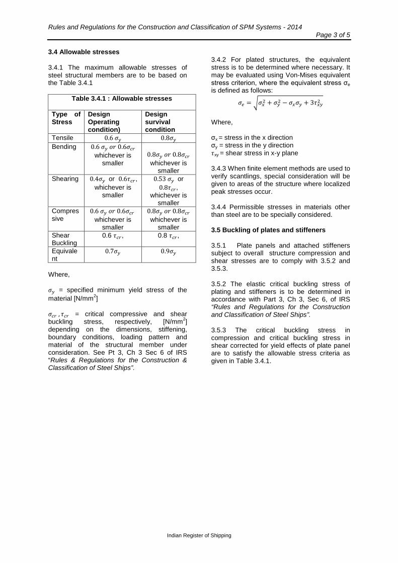
Rules and Regulations for the Construction and Classification of SPM Systems - 2014 Page 3 of 5
Indian Register of Shipping
3.4 Allowable stresses
3.4.1 The maximum allowable stresses of steel structural members are to be based on the Table 3.4.1
Table 3.4.1 : Allowable stresses
Type of Stress
Design Operating condition)
Design survival condition
Tensile 0.6 𝜎𝑦 0.8𝜎𝑦 Bending 0.6 𝜎𝑦 𝑜𝑟 0.6𝜎𝑐𝑟
whichever is smaller
0.8𝜎𝑦 𝑜𝑟 0.8𝜎𝑐𝑟
whichever is smaller
Shearing 0.4𝜎𝑦 or 0.6𝜏𝑐𝑟, whichever is
smaller
0.53 𝜎𝑦 or 0.8𝜏𝑐𝑟,
whichever is smaller
Compressive
0.6 𝜎𝑦 𝑜𝑟 0.6𝜎𝑐𝑟 whichever is
smaller
0.8𝜎𝑦 𝑜𝑟 0.8𝜎𝑐𝑟 whichever is
smaller Shear Buckling
0.6 𝜏𝑐𝑟, 0.8 𝜏𝑐𝑟,
Equivalent
0.7𝜎𝑦 0.9𝜎𝑦
Where, 𝜎𝑦 = specified minimum yield stress of the material [N/mm2] 𝜎𝑐𝑟 , 𝜏𝑐𝑟 = critical compressive and shear buckling stress, respectively, [N/mm2] depending on the dimensions, stiffening, boundary conditions, loading pattern and material of the structural member under consideration. See Pt 3, Ch 3 Sec 6 of IRS “Rules & Regulations for the Construction & Classification of Steel Ships”.
3.4.2 For plated structures, the equivalent stress is to be determined where necessary. It may be evaluated using Von-Mises equivalent stress criterion, where the equivalent stress σe is defined as follows:
𝜎𝑒 = �𝜎𝑥2 + 𝜎𝑦2 − 𝜎𝑥𝜎𝑦 + 3𝜏𝑥𝑦2
Where, σx = stress in the x direction σy = stress in the y direction 𝜏xy = shear stress in x-y plane 3.4.3 When finite element methods are used to verify scantlings, special consideration will be given to areas of the structure where localized peak stresses occur. 3.4.4 Permissible stresses in materials other than steel are to be specially considered. 3.5 Buckling of plates and stiffeners 3.5.1 Plate panels and attached stiffeners subject to overall structure compression and shear stresses are to comply with 3.5.2 and 3.5.3. 3.5.2 The elastic critical buckling stress of plating and stiffeners is to be determined in accordance with Part 3, Ch 3, Sec 6, of IRS “Rules and Regulations for the Construction and Classification of Steel Ships”. 3.5.3 The critical buckling stress in compression and critical buckling stress in shear corrected for yield effects of plate panel are to satisfy the allowable stress criteria as given in Table 3.4.1.
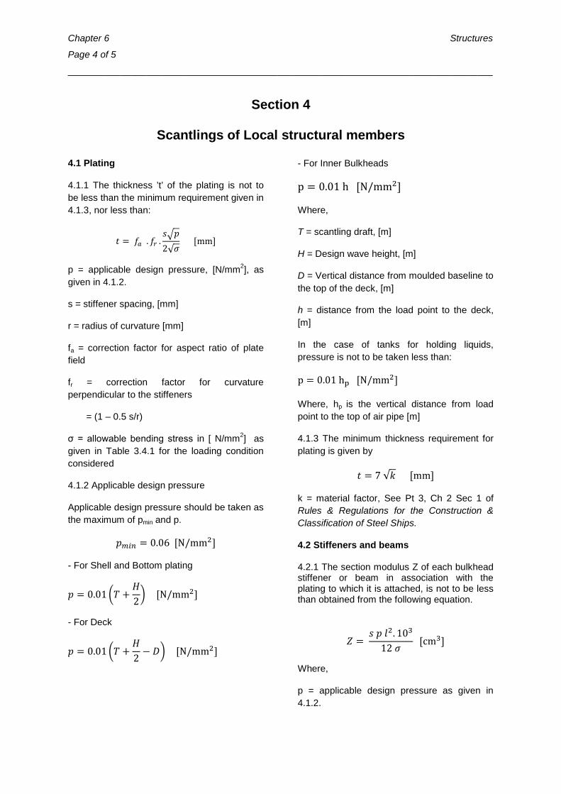
Chapter 6 Structures
Page 4 of 5
_________________________________________________________________________________
Section 4
Scantlings of Local structural members
4.1 Plating
4.1.1 The thickness ’t’ of the plating is not to be less than the minimum requirement given in 4.1.3, nor less than:
𝑡 = 𝑓𝑎 . 𝑓𝑟 .𝑠�𝑝2√𝜎
[mm]
p = applicable design pressure, [N/mm2], as given in 4.1.2.
s = stiffener spacing, [mm]
r = radius of curvature [mm]
fa = correction factor for aspect ratio of plate field
fr = correction factor for curvature perpendicular to the stiffeners
= (1 – 0.5 s/r)
σ = allowable bending stress in [ N/mm2] as given in Table 3.4.1 for the loading condition considered
4.1.2 Applicable design pressure
Applicable design pressure should be taken as the maximum of pmin and p.
𝑝𝑚𝑖𝑛 = 0.06 [N/mm2]
- For Shell and Bottom plating
𝑝 = 0.01 �𝑇 +𝐻2� [N/mm2]
- For Deck
𝑝 = 0.01 �𝑇 +𝐻2− 𝐷� [N/mm2]
- For Inner Bulkheads
p = 0.01 h [N/mm2]
Where,
T = scantling draft, [m]
H = Design wave height, [m]
D = Vertical distance from moulded baseline to the top of the deck, [m]
h = distance from the load point to the deck, [m]
In the case of tanks for holding liquids, pressure is not to be taken less than:
p = 0.01 hp [N/mm2]
Where, hp is the vertical distance from load point to the top of air pipe [m]
4.1.3 The minimum thickness requirement for plating is given by
𝑡 = 7 √𝑘 [mm]
k = material factor, See Pt 3, Ch 2 Sec 1 of Rules & Regulations for the Construction & Classification of Steel Ships.
4.2 Stiffeners and beams
4.2.1 The section modulus Z of each bulkhead stiffener or beam in association with the plating to which it is attached, is not to be less than obtained from the following equation.
𝑍 = 𝑠 𝑝 𝑙2. 103
12 𝜎 [cm3]
Where,
p = applicable design pressure as given in 4.1.2.
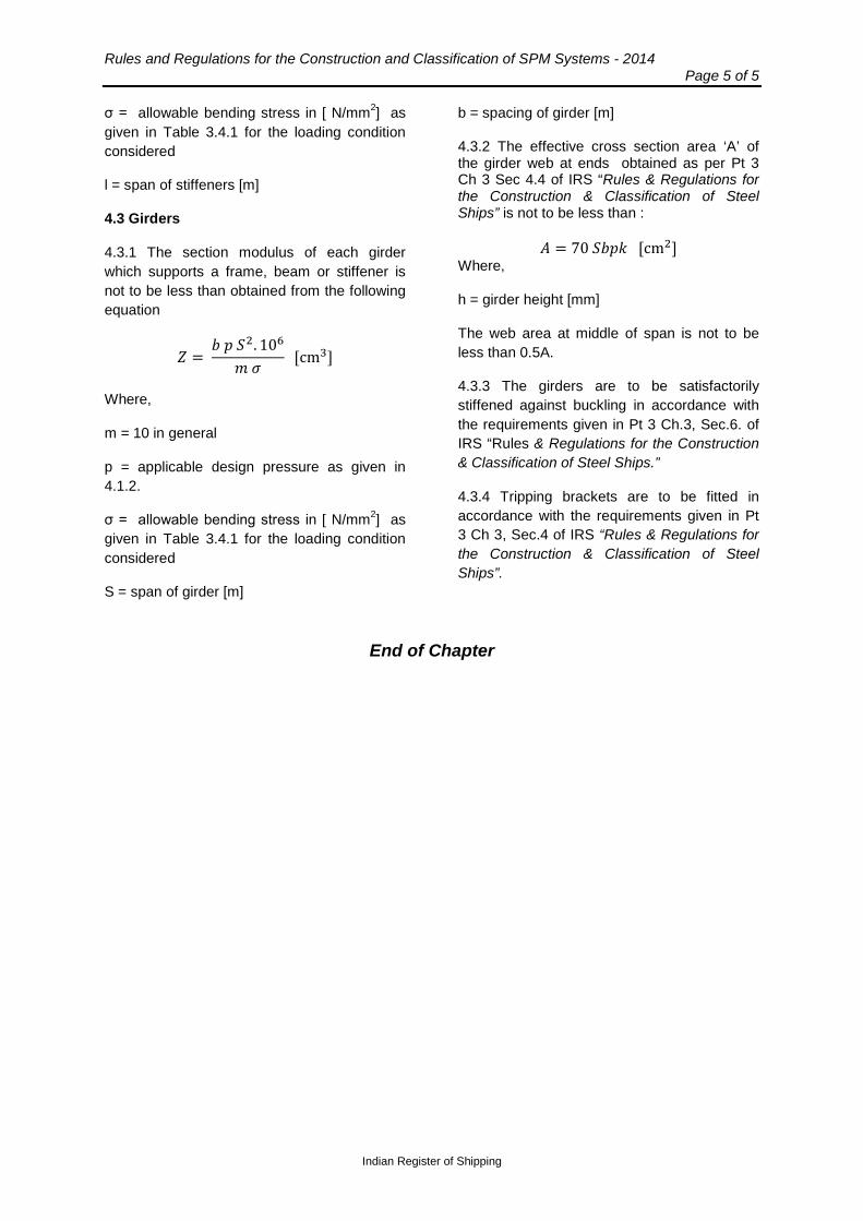
Rules and Regulations for the Construction and Classification of SPM Systems - 2014 Page 5 of 5
Indian Register of Shipping
σ = allowable bending stress in [ N/mm2] as given in Table 3.4.1 for the loading condition considered
l = span of stiffeners [m]
4.3 Girders
4.3.1 The section modulus of each girder which supports a frame, beam or stiffener is not to be less than obtained from the following equation
𝑍 = 𝑏 𝑝 𝑆2. 106
𝑚 𝜎 [cm3]
Where,
m = 10 in general
p = applicable design pressure as given in 4.1.2.
σ = allowable bending stress in [ N/mm2] as given in Table 3.4.1 for the loading condition considered
S = span of girder [m]
b = spacing of girder [m]
4.3.2 The effective cross section area ‘A’ of the girder web at ends obtained as per Pt 3 Ch 3 Sec 4.4 of IRS “Rules & Regulations for the Construction & Classification of Steel Ships” is not to be less than :
𝐴 = 70 𝑆𝑏𝑝𝑘 [cm2] Where,
h = girder height [mm]
The web area at middle of span is not to be less than 0.5A.
4.3.3 The girders are to be satisfactorily stiffened against buckling in accordance with the requirements given in Pt 3 Ch.3, Sec.6. of IRS “Rules & Regulations for the Construction & Classification of Steel Ships.”
4.3.4 Tripping brackets are to be fitted in accordance with the requirements given in Pt 3 Ch 3, Sec.4 of IRS “Rules & Regulations for the Construction & Classification of Steel Ships”.
End of Chapter
Rules and Regulations for the Construction and Classification of SPM Systems - 2014 Page 1 of 3
_________________________________________________________________________________
Indian Register of Shipping
Chapter 7
Survey and Testing during Construction
Contents
Section
1 General
2 Testing of tanks and tight boundaries
3 Mooring System
4 Cargo transfer, Control and Safety Systems
Section 1
General
1.1 General 1.1.1 The requirements for survey and testing during construction of various components of the SPM unit are as indicated in 1.1.2 to 1.1.4. 1.1.2 The following items are to be surveyed during construction and testing: a) Buoy Structure, b) Buoyancy Elements c) PLEM Structure d) Piles/ anchors e) Cargo/ product swivel f) Hydraulic swivel g) SPM Main Bearing h) Flexible risers, Underbuoy hoses i) Floating hoses j) Leak reservoir
The survey will include verification of materials for traceability and acceptability, review of welding procedures and welder qualifications, examination of fit-up, alignment, NDT and satisfactory testing.
1.1.3 The following items may be accepted based on witness of satisfactory testing by the surveyor:
a) Mooring chain/ ropes and mooring components
b) Load pins c) Winches d) Leak-recovery system
1.1.4 The following items may be accepted based on supplier’s documentation to the effect that they are designed, manufactured and tested as per applicable standards.
a) Expansion joints in piping b) Valves, fittings and flanges c) Mooring hawser, chafing chain d) Electrical controls e) Navigation aids f) Hydraulic power units g) Umbilical h) Pig launcher.
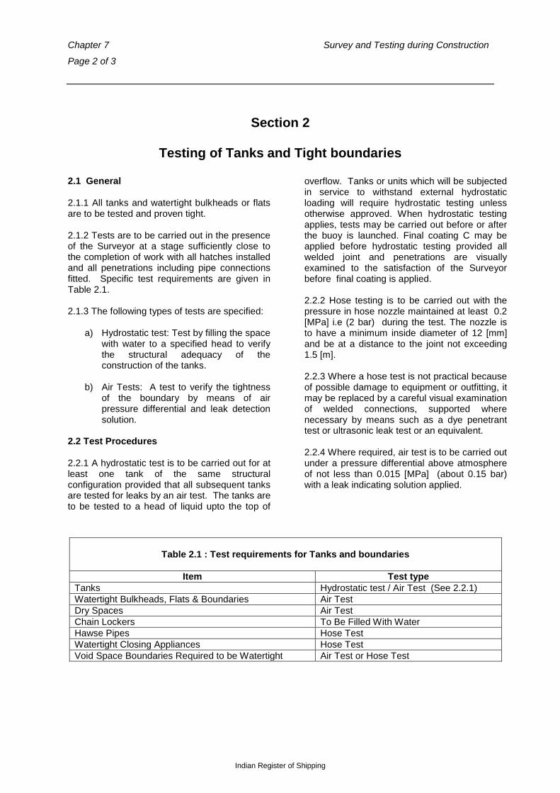
Chapter 7 Survey and Testing during Construction
Page 2 of 3
Indian Register of Shipping
Section 2
Testing of Tanks and Tight boundaries 2.1 General 2.1.1 All tanks and watertight bulkheads or flats are to be tested and proven tight. 2.1.2 Tests are to be carried out in the presence of the Surveyor at a stage sufficiently close to the completion of work with all hatches installed and all penetrations including pipe connections fitted. Specific test requirements are given in Table 2.1. 2.1.3 The following types of tests are specified:
a) Hydrostatic test: Test by filling the space with water to a specified head to verify the structural adequacy of the construction of the tanks.
b) Air Tests: A test to verify the tightness of the boundary by means of air pressure differential and leak detection solution.
2.2 Test Procedures 2.2.1 A hydrostatic test is to be carried out for at least one tank of the same structural configuration provided that all subsequent tanks are tested for leaks by an air test. The tanks are to be tested to a head of liquid upto the top of
overflow. Tanks or units which will be subjected in service to withstand external hydrostatic loading will require hydrostatic testing unless otherwise approved. When hydrostatic testing applies, tests may be carried out before or after the buoy is launched. Final coating C may be applied before hydrostatic testing provided all welded joint and penetrations are visually examined to the satisfaction of the Surveyor before final coating is applied. 2.2.2 Hose testing is to be carried out with the pressure in hose nozzle maintained at least 0.2 [MPa] i.e (2 bar) during the test. The nozzle is to have a minimum inside diameter of 12 [mm] and be at a distance to the joint not exceeding 1.5 [m]. 2.2.3 Where a hose test is not practical because of possible damage to equipment or outfitting, it may be replaced by a careful visual examination of welded connections, supported where necessary by means such as a dye penetrant test or ultrasonic leak test or an equivalent. 2.2.4 Where required, air test is to be carried out under a pressure differential above atmosphere of not less than 0.015 [MPa] (about 0.15 bar) with a leak indicating solution applied.
Table 2.1 : Test requirements for Tanks and boundaries
Item Test type Tanks Hydrostatic test / Air Test (See 2.2.1) Watertight Bulkheads, Flats & Boundaries Air Test Dry Spaces Air Test Chain Lockers To Be Filled With Water Hawse Pipes Hose Test Watertight Closing Appliances Hose Test Void Space Boundaries Required to be Watertight Air Test or Hose Test
Rules and Regulations for the Construction and Classification of SPM Systems - 2014 Page 3 of 3
_________________________________________________________________________________
Indian Register of Shipping
Section 3
Mooring System
3.1 Anchor legs and their attachments to the buoy are to be examined. Proper fitting of components, connectors and securing devices is to be verified. 3.2 The components of the anchor Legs (f mooring chains, connecting shackles, connecting links, and other fittings) are to be in accordance with Part 2, Ch 10, Sec 5 of the Rules and Regulations for the Construction and Classification of Steel Ships s and tested in the presence of the attending Surveyor. Each mooring leg is to be pull tested upon installation in accordance with an approved procedure in
the presence of a Surveyor in accordance with Ch 8, Sec 2. 3.3 Mooring hawsers are to be examined for proper fitting and securing of all components.. 3.4 Piles or gravity boxes where used in the anchoring system are to be subject to NDT. 3.5 Surveys regarding the manufacturing and testing of anchors are to be in accordance with Pt 2, Ch 10, Sec 1 of Rules and Regulations for the Construction and Classification of Steel Ships.
Section 4
Cargo transfer, Control and Safety Systems 4.1 The requirements for testing of cargo transfer system and control and safety systems are to be in accordance with Chapter 9.
End Of Chapter

Rules and Regulations for the Construction and Classification of SPM Systems - 2014 Page 1 of 3
____________________________________________________________________________________
Indian Register of Shipping
Chapter 8
Anchoring and Mooring
Contents
Section
1 General
2 Anchoring
3 Mooring
Section 1
General
1.1 General
1.1.1 Sufficient redundancy is to be provided in the mooring system of the SPM so as to prevent failure of the underbuoy hose or riser when one anchor line is not effective. This is to be verified
for the operating and survival conditions specified in Chapter 4. Alternatively, means may be provided for the isolation of the SPM from the undersea pipeline.
Section 2
Anchoring
2.1 Anchor Lines
2.1.1 Anchor lines are to have adequate clearance from subsea equipment such as templates, flow lines, etc. 2.1.2 The design of the mooring system is to take account of the offset limits required by the riser system, and the avoidance of contact between risers and anchor lines. 2.1.3 In general, the break strength of the anchor line is not to be greater than the load bearing capacity of the connecting structure
2.1.4 The fatigue life of the main components of mooring system is to be verified. Calculations are to be submitted. Fatigue life calculations for anchor lines may be carried out in accordance with API 2SK: “Recommended Practice for Design and Analysis of Station keeping Systems for Floating Structures”. 2.1.5 In areas where fast weardown of chain due to continuous sand abrasion is possible, special measures are to be taken which may include frequent periodic inspection and renewal or increase in chain size.

Chapter 8 Anchoring and Mooring
Page 2 of 3
2.2 Anchor Points
2.2.1 Where drag anchors are used for mooring, their holding capacity is to be evaluated based on the anchor type and the seabed soil conditions. The load on each anchor line is to be evaluated for the design operating and survival conditions. 2.2.2 The design factor of safety with respect to the holding capacity of the anchor is not to be less than 2.00 for the operating condition with the vessel moored to the SPM, and not less than 1.50 for the design storm condition (without the vessel). 2.2.3 Where anchor piles are used, pile foundations may be designed based on relevant requirements in standard API RP 2A “Recommended Practice for planning, designing and constructing fixed offshore platforms”. A pile driving record or pile grouting record is to be submitted for each pile. 2.2.4 Any gravity boxes used in the anchor legs are to be evaluated for resistance against sliding, uplifting, and overturning. The forces due to environment, gravity and mooring and scour effects are to be considered. 2.2.5 On deployment of the mooring system with drag anchors, each mooring line is to be pull tested to 80% of the maximum design load and is to be held at that load for 30 minutes in presence of the Surveyor. The soil penetration
depth of the anchors are to be verified to conform to the design requirements. 2.3 Anchor Legs
2.3.1 The components of each anchor leg are to be designed with the following safety factors of against breaking. Design Survival Condition without vessel All Lines Intact 2.50 Design Operating Condition with vessel All Lines Intact 3.00 The factor of safety in the design operating condition may be reduced to that in the design survival condition provided a mooring analysis of the system with any one line broken shows that a factor of safety of 2.00 is available with respect to the minimum breaking strength of anchor Ieg component(s). In this case the factor of safety for holding power of individual anchors with one line broken is not to be less than 1.6. (See 2.2.2). 2.4 Anchors and chain
2.4.1 Anchors and chains are to satisfy the requirements of Part 2, Ch 10 sections 1 and 5 respectively of IRS “Rules and Regulations for the construction and classification of Steel Ships”.
Rules and Regulations for the Construction and Classification of SPM Systems - 2014 Page 3 of 3
____________________________________________________________________________________
Indian Register of Shipping
Section 3
Mooring
3.1 Mooring between Vessel and SPM
3.1.1 The factor of safety of a hawser against its breaking strength is not to be less than 1.67 in the case of single fairlead and 2.50 for two fairleads. (see Part 5 Ch 28 of IRS Rules and Regulations for the construction and classification of steel ships for details of arrangement on the connected vessel) The breaking strength of the hawser to be used is to be the lower value of the hawser in wet or dry condition.
3.1.2 Hawser and chafe chain are to be manufactured in compliance with the OCIMF Guidelines for Purchasing and Testing of SPM hawsers". 3.2 Structural Components
3.2.1 The structural components of the mooring system (chain stoppers, fairleads, shackles, etc.) are to be designed to withstand 1.25 times the minimum breaking load of the mooring line without yield.
End of Chapter

Rules and Regulations for the Construction and Classification of SPM Systems - 2014 Page 1 of 9
_________________________________________________________________________________
Indian Register of Shipping
Chapter 9
Systems and Equipment
Contents
Section
1 Cargo or Product Transfer Systems
2 Ancillary Systems and Equipment
3 Control and Monitoring Systems
4 Gas Detection Systems
Section 1
Cargo or Product Transfer Systems
1.1 General 1.1.1 The requirements in this section apply to the cargo or product transfer system which includes all system components from the seafloor pipe line connection to the first flange on the loading tanker or other type of unit. Pipe Line End Manifolds (PLEMs) are also to comply with the provisions of this section. 1.2 Sea bed pipeline Connection 1.2.1 The PLEM or connection between the undersea pipeline and the underbuoy hoses/flexible risers is to be anchored to the sea bottom to resist forces due to waves, current, and forces imposed by the SPM and the undersea pipeline. 1.2.2 Loads on the PLEM and the buoy from the underbuoy hoses/ flexible riser are to be calculated from an appropriate analysis. The structural design calculations of the PLEM and its foundation are to be submitted for approval. 1.2.3 A means of closure is to be provided to permit isolation of the SPM from the undersea pipeline. 1.3 Materials 1.3.1 Requirements for materials in Ch 3 section 1 are to be complied with for cargo or product transfer systems.
1.4 Hoses/Flexible Risers 1.4.1 Underbuoy Hoses/Flexible Risers 1.4.1.1 The effect of currents and waves and resulting displacements of the underbuoy pipes are to be evaluated. Dynamic analyses shall be performed (fully or partially coupled) with sensitivity to water depth, product densities and combinations of environmental conditions (directions). The extreme tension, shear force, curvature along the hose strings is to be assessed in operating and survival conditions, with tanker connected and not connected. 1.4.1.2 The load cases selected for analysis are to be corresponding to the most unfavorable combinations of vessel offsets and current / wave loadings. 1.4.1.3 An analysis of interference is to be performed in order to verify that all the underbuoy pipes, umbilical and anchor lines remain at an acceptable distance from each other (and from the buoy) to prevent any interference during operation. 1.4.1.4 The fatigue life of the underbuoy pipes is to be assessed. 1.4.1.5 Each underbuoy pipe and associated components is to be designed, fabricated, tested and installed in accordance with the requirements of a recognized standard acceptable to IRS, such as the following:

Chapter 9 Systems and Equipment
Page 2 of 9
For flexible underbuoy pipe systems:
• API RP 17B "Recommended Practice for Flexible Pipe".
• API Spec 17J “Specification for Unbonded Flexible Pipe”
• API Spec 17K “Specification for bonded Flexible Pipe”
For rigid under buoy pipe system::
• API RP 2RD • API RP 1111
1.4.1.6 The procedures for installation, removal (if applicable), and maintenance are to be submitted for review. 1.4.2 Floating Hoses 1.4.2.1 The dimensions and the type of reinforcement for floating hoses are to be determined from strength analysis of the hose system taking into account design pressure differential, product flow, weight of hose with contents, buoyancy forces, wave forces, accelerations and relative motions. 1.4.2.2 Lifting arrangements are to be provided at the end of the floating hose. 1.4.2.3 Special hose is to be provided at the vessel end to accommodate the bending of the hose over the vessel rail (Tanker Rail Hose). 1.4.2.4 The vessel end of the hose is to be provided with a blind flange to avoid contamination of the sea water. 1.4.2.5 Consideration is to be given to providing swivels, specially reinforced hose, or both, at the connection of the floating hose with components of the SPM system. 1.4.2.6 A weak link is to be provided for the floating hose. Consideration is to be given to providing a breakaway coupling with shut off valves in each floating hose string to provide surge and axial overload protection to the hose string, and to minimize pollution in the event of an excessive pressure surge or tanker breakout. 1.4.2.7 The hose is to be properly arranged with respect to support and configuration during loading as well as when the terminal is unoccupied in order to restrict the curvature and to reduce change of curvature and
thereby fatigue effects. The loading hose is to be properly protected against fouling and mechanical damage. 1.4.2.8 In general, all hoses are to comply with the OCIMF "Guide to Manufacturing and Purchasing Hoses for Offshore Moorings" and is to be manufactured under IRS Survey. Other standards may be specially considered. Prototype hose approval is required. 1.4.3 System Design Pressure 1.4.3.1 The design pressure of the cargo transfer system is to be taken as the larger of: a) The shut-off head at the vessel's manifold at zero flow, plus the gravity head of the contents to the part of the SPM pipe or hose in question. b) The head calculated due to surge pressure, resulting from design valve closing times. 1.4.4 Testing 1.4.4.1 Each length of hose is to be subjected to hydrostatic and vacuum tests in accordance with requirements of 1.11.6 and 1.11.8 respectively of the OCIMF “Guide to Manufacturing and Purchasing Hoses for Offshore Moorings". 1.4.4.2 These tests are to be witnessed by a Surveyor. In all cases where the design pressure of the system exceeds 15.5 bar, (0.155 [MPa]) the hydrostatic test is to be carried out at not less than the design pressure. 1.5 Swivels 1.5.1 Design 1.5.1.1 Piping swivels are to be of material which is compatible with the transported products. Where multiple product swivels are used, material used for each product path is to be compatible to the specific product being transported through it. 1.5.1.2 Details of the swivel connecting stationary SPM piping with rotating piping are to be submitted for approval. Such details are to include fixed and rotating parts details, plate thicknesses, nozzle locations and arrangement, seal and bearing design, and welding.
Rules and Regulations for the Construction and Classification of SPM Systems - 2014 Page 3 of 9
_________________________________________________________________________________
Indian Register of Shipping
1.5.1.3 The swivel design is to consider the most adverse combination of applicable loads. At least the following loads are to be considered:
1. Starting torque required for each swivel at maximum design pressure 2. Weight of swivel and its structural components 3. Dynamic loads due to vessel motion 4. Piping loads 5. Mooring forces
6. Pressure loads 7. Thermal loads
1.5.1.4 Piping loads on the swivel are to be minimized by means of suitable expansion joints or other means. 1.5.1.5 Pressure retaining components of the swivel are to be designed in accordance with a recognized standard such as the ASME Boiler and Pressure Vessel Code. 1.5.1.6 Structural components of the swivel and driving mechanism are to comply with Ch 6 of these Rules or a recognized standard. 1.5.2 Testing 1.5.2.1 Testing is to be conducted in accordance with an approved test procedure in the presence of a Surveyor. 1.5.2.2 The procedure is to address acceptable leakage criteria. The following tests are to be carried out:
1. Hydrostatic pressure test according to the applied design code for the swivel or to 1.5 times the design pressure fort two (2) hours. 2. Hydrostatic pressure test to design pressure through two (2) complete revolutions in each direction at a rate of approximately ten (10) minutes per revolution. 3. Hydrostatic pressure test to design pressure through four (4) complete revolutions. The first revolution is to be clockwise, and the final
counterclockwise. Each rotation is to be in stages of 30 degrees at a rate of approximately 30 seconds per 30 degrees with a 30 second pause between each 30 degree rotation. For each 30 degree rotation, the starting torque and the running torque are to be recorded. Where product assembly swivel rotates in unison with mooring swivel, this test is to be conducted on the combined system.
1.5.3 Corrosion Protection 1.5.3.1 The swivels are to be coated on the outside with a suitable corrosion resistant coating. 1.5.3.2 This coating will not be required for parts made of corrosion resistant material. 1.5.3.3 The possibility of corrosion due to the presence of CO2, O2 or H2S in the cargo or product is to be considered in the swivel design. Also refer to Ch3, Sec 2 for corrosion protection. 1.5.4 Electrical swivels 1.5.4.1 Electrical swivels, where provided, are to be suitable for the hazardous area in which they are located. 1.5.4.2 Electrical swivels are to be subjected to dielectric and insulation resistance tests. A continuity test is to be performed with the swivel in rotation. 1.6 Leak Monitoring and Recovery System: 1.6.1 All piping for leak recovery systems is to be of steel construction or equivalent and designed in accordance with ASME B31.3 or other recognized standard. 1.7 Bearings 1.7.1 General 1.7.1.1 Rolling element, pad and journal bearings used in swivel units are to be designed for the static and dynamic loadings which are expected in service. Bearing pressure and fatigue life calculations are to be submitted. 1.7.1.2 The design of bearings, joints, etc., is to be in accordance with an acceptable design
Chapter 9 Systems and Equipment
Page 4 of 9
method or an internationally recognized Code or Standard. 1.7.1.3 Where necessary, suitable lubricating arrangements are to be fitted to all adjacent bearing surfaces to maintain an adequate and continuous supply of lubricant to the surfaces during all unattended periods. 1.7.1.4 Bearing surfaces are to be adequately protected from deterioration caused by the ingress of seawater and other contaminants by a system of seals or other suitable alternative methods. 1.7.2 Main Bearing 1.7.2.1 In the case of SPM main bearings of the ball and roller type the following aspects are to be considered:
a) Plastic deformation of rolling elements and raceways.
b) Fatigue of critical sections of outer and inner rings.
c) Load capacity (yield) of the whole bearing based on the capacities of the bolts and ring cross sections having regard to the rigidity of the supporting structures.
1.7.2.2 Turret roller bearings may be monitored in service by condition monitoring the bearing lubrication fluid. 1.7.3 Mooring Bearings 1.7.3.1 Bearings which carry the operating hawser load, rotating structure load and mooring load are to be designed with a safety factor of not less than 2 without yielding of the bearing surfaces. 1.7.3.2 Bearing mounting bolts are to be designed in accordance with recognized standards. For high tension bolts stress corrosion cracking is to be considered. 1.8 Bearing Support Structure 1.8.1 Bearing support structures are to be assessed for fatigue damage due to cyclic loading. 1.8.2 Permissible stress levels in supporting structure are to be in accordance with those specified in Ch 6, 3.4. 1.8.3 An acceptable method for the determination of flanged bolt loads is to be
used from suitable internationally recognized Codes or Standards. 1.8.4 For joints subject to fatigue loading, the bolts are to be of ISO 898/1 Material Grade 8.8, 10.9 or 12.9, or equivalent. They are to be pre-tensioned by a controlled means to 70 to 90 per cent of their yield stress. For bolt sizes greater than M30, pre-tensioning must be carried out, in a rational order, by a hydraulic tensioning device. 1.8.8 The torque on all bolting on bearing housing, support structures and attachments is to be regularly inspected and checked. 1.9 Seals 1.9.1 Leakage of lubrication fluid and subsequent ingress of sea-water is to be prevented by installing a suitable system of seals. 1.9.2 Seals are to be made of suitable material for the intended service. In the case of swivel seals, compatibility of the seal material with the product is to be ensured. 1.9.3 The seal seats and travelling surfaces should be corrosion-resistant and of sufficient hardness to prevent excessive abrasion and wear. 1.10 Cargo or Product Piping Systems 1.10.1 Piping 1.10.1.1 All piping for the cargo or product transfer system mounted on the SPM buoy is to be of steel with welded or flanged connections. 1.10.1.2 Piping is to be securely mounted on the SPM and anchored to resist the forces resulting from internal pressure and flow in the system and loads induced by the hose/flexible riser system connected to it. 1.10.1.3 Provision is to be made for expansion. 1.10.1.4 Piping is to be shop tested after fabrication to a minimum pressure of 1.5 times the design pressure in the presence of a Surveyor. 1.10.1.5 Cargo or product piping installed on SPMs is to comply with ASME B31.3 and other applicable recognized standard. Piping

Rules and Regulations for the Construction and Classification of SPM Systems - 2014 Page 5 of 9
_________________________________________________________________________________
Indian Register of Shipping
of less than ANSI schedule 40 thickness is not to be used. 1.10.2 Valves and fittings 1.10.2.1 A shut-off valve is to be provided on the SPM for each cargo transfer line. 1.10.2.2 Valves are to be of steel construction and capable of manual operation. 1.10.2.3 Valves and fittings are to be constructed and tested in accordance with recognized standards. Non-standard valves and fittings will be specially considered by IRS. 1.10.3 Expansion Joints 1.10.3.1 Expansion joints are to have a maximum allowable working pressure of no greater than one third of the hydrostatic bursting pressure of the joint. Results of burst test of the joint are to be submitted. 1.10.3.2 Details of materials and construction of the expansion joints are to be submitted for approval. 1.10.4 PLEM piping 1.10.4.1 The requirements of 1.10.1 and 1.10.2 are also applicable to the piping,
valves, flanges and fittings forming the Pipe Line End Manifold (PLEM). 1.10.4.2 Alternatively, the PLEM may also be constructed and tested in accordance with ASME B31.4 Pipeline Transportation Systems for Liquid Hydrocarbons and Other Liquids. 1.10.5 Corrosion Protection 1.10.5.1 The cargo or product piping, valves and fittings are to be coated on the outside with a suitable corrosion resistant coating. 1.10.5.2 This coating will not be required for parts made of corrosion resistant material. 1.10.5.3 The possibility of corrosion due to the presence of CO2, O2, or H2S in the cargo or product is to be considered in the piping design. Also refer to Ch3, Sec 3 for corrosion protection. 1.11 Installation testing 1.11.1 The entire cargo transfer system including hoses/flexible risers, swivels, and valves is to be hydrostatically tested after installation to the design pressure.
Section 2
Ancillary Systems and Equipment
2.1 General 2.1.1 This section gives specific requirements for ancillary systems provided on a single point mooring. Applicable requirements of Chapter 12 of IRS Rules for Mobile Offshore Drilling Units are to be complied with unless otherwise specified in this section. 2.2 Bilge – Drainage System 2.2.1 SPM buoys are to be provided with a means for pumping from and draining all tanks and void compartments. 2.2.2 Pumping by means of a portable hand operated pump would be acceptable in lieu of a fixed bilge system.
2.2.3 Scuppers or other arrangements are to provided on the SPM buoy to permit the drainage of water likely to accumulate on the buoy deck. 2.3 Sounding System 2.3.1 All tanks and other compartments are to be provided with sounding system. A manual means of sounding is acceptable. 2.4 Venting System (where applicable) 2.4.1 All tanks that are filled or emptied through fixed pumping arrangements or which are used as reception tanks for pressure relief valves are to be fitted with vent pipes. All voids through which pressure piping passes are also to be fitted with vent pipes.

Chapter 9 Systems and Equipment
Page 6 of 9
2.4.2 The structural arrangement of tanks or voids requiring a vent is to be such as to permit the free passage of air and gases from all parts of the spaces to the vent pipes. 2.4.3 Each tank or void requiring a vent is to be fitted with at least one vent pipe, which is located at the highest part of the tank. 2.4.4 Vent pipes are to be arranged to provide adequate self-drainage under normal conditions. 2.4.5 Vent outlets on the open deck are to terminate by way of return bends. Satisfactory means, permanently attached, are to be provided for closing the vent pipes. 2.4.6 The internal diameter of each vent pipe is not to be less than 50 mm unless specially approved otherwise. 2.4.7 Where tanks are to be filled by pump pressure, the aggregate area of the vents on the tank is to be at least 125% of the effective area of the filling line. Notwithstanding the above, the pump capacity and pressure head are to be considered in the sizing of the vents.
2.4.4 Vent pipes are to terminate in the weather and their height is to be at least 760 mm above the deck. Lower heights may be accepted where it is essential for the working of the SPM. In such cases, efficient permanently attached automatic closing appliances are generally required. 2.5 Ancillary Components 2.5.1 Ancillary mechanical components such as hoists, winches, quick connect and disconnect devices, are to be designed in accordance with applicable industry standards, codes and published recommended practices. 2.6 Pollution Prevention 2.6.1 Sumps are to be provided at potential spillage points and drainage systems are to have adequate capacity and be designed for ease of cleaning 2.6.2 In open areas, arrangement are to be such that oil spillage will be contained, and suitable drainage and recovery provisions are made that comply with the requirements of State authority.
Section 3
Electrical Installations
3.1 General 3.1.1 This section gives specific requirements for electrical installations on Single Point Mooring. Applicable requirements of Ch 13 of IRS Rules for Mobile Offshore Drilling Units are to be complied with unless otherwise specified in this section. Alternatively, compliance with recognized standards instead of the above rules will be specially considered. 3.1.2 Requirements for electrical installations in hazardous areas are given in Ch 10, Sec 3. 3.2 Source of Power 3.2.1 Main source of electrical power 3.2.1.1 SPM is to be provided with a main source of electrical power of sufficient capacity to satisfy all the operating services.
3.2.1.2 Where renewable sources of energy are used, stationary batteries are to be provided to guarantee the distribution of the electrical power during the time without sun or wind. The battery system is to be subjected to approval by IRS. 3.2.2 Emergency source of electrical power 3.2.2.1 A self contained emergency source of electrical power is to be provided. 3.2.2.2 The emergency source of power is to be provided for following services:
• Navigation aids • Control systems
3.2.2.3 The emergency source of power is to be capable to guarantee the supply with minimum of 96 hours of navigation aids (signal lights and fog horn).
Rules and Regulations for the Construction and Classification of SPM Systems - 2014 Page 7 of 9
_________________________________________________________________________________
Indian Register of Shipping
3.3 Equipment 3.3.1 Photo-voltaic System 3.3.1.1 Solar panels are to be designed and manufactured according to IEC 61215.
3.3.1.2 Solar panels are to be designed to be highly resistant to salty water and hail impact. They are to be provided with bird spikes 3.3.1.3 The system is to be sized in a way that it guarantees the power for normal operating conditions and ensures, with certainty the supply of the loads even in periods of “no sun”.
Section 4
Control and Monitoring Systems 4.1 General 4.1.1 Control and monitoring systems are to be based on the fail safe principle. 4.1.2 Choice of data transmission medium (electric or fibre optic cable, radio) for remote monitoring is to be made according to the environmental conditions. 4.1.3 Safety functions are not to be impaired in case of failure of the data transmission link between the offloading buoy and the main control station. 4.1.4 Failure of data transmission is to generate an alarm at the main control station. 4.2 Control of product transfer system 4.2.1 The loading system is to be provided with product transfer monitoring display either at a local of central control station. 4.2.2 The control system is to be designed such that pumps cannot be operated until specific valves are opened and the connection to the loading ship has been successfully completed. The pumps are to stop immediately upon commencement of an emergency disconnection procedure. 4.2.3 Pressure sensors are to be located at suitable positions to secure loading pump shut down if the line pressure exceeds the maximum allowable pressure by a preset amount or drops below a preset minimum value.
4.2.4 Interlocks are to be provided to ensure that:
• Main control valves cannot be opened unless the coupling is connected to the mating flange.
• Outboard and in board valves
adjacent to the coupling are closed before the coupling can be released.
4.2.5 Accumulators are to be provided for hydraulic operated valves. The accumulators are to be of sufficient capacity to close valves and release the coupling. 4.3 Hawser load monitoring 4.3.1 SPM installations are to be provided with an approved means of monitoring the load occurring in the mooring hawser connecting the SPM to the ship. This equipment is to be designed so that automatic warning is given to the ship in the event that tension in the mooring hawser exceeds designed limits. Warning is to be both visual and audible alarm. 4.3.2 The load level designated to initiate automatic warning is to be below the maximum allowable hawser load level by sufficient margin to allow such steps to be taken as may be necessary, to prevent excessive loads, or to prepare for ship disconnection from the SPM. 4.3.3 The load level designated to initiate the automatic warning should be set giving due consideration to the safe working load of chain stoppers fitted to the attending vessel.
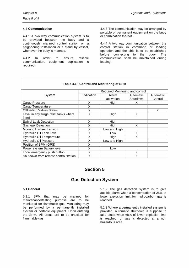
Chapter 9 Systems and Equipment
Page 8 of 9
4.4 Communication 4.4.1 A two way communication system is to be provided between the buoy and a continuously manned control station on a neighboring installation or a stand by vessel, whenever the buoy is manned. 4.4.2 In order to ensure reliable communication, equipment duplication is required.
4.4.3 The communication may be arranged by portable or permanent equipment on the buoy or combination thereof. 4.4.4 A two way communication between the control station in command of loading operation and the ship is to be established before connecting to the buoy. The communication shall be maintained during loading.
Table 4.1 : Control and Monitoring of SPM
System Required Monitoring and control
Indication Alarm activation
Automatic Shutdown
Automatic Control
Cargo Pressure X High X Cargo Temperature X Offloading Valves Status X X Level in any surge relief tanks where fitted
X High X
Swivel Leak Detection X High Gas leak Detection X High X Mooring Hawser Tension X Low and High Hydraulic Oil Tank Level X Low X Hydraulic Oil Temperature X High X Hydraulic Oil Pressure X Low and High Position of SPM (GPS) X Power system Battery level X Low Local emergency push button X X Shutdown from remote control station X X
Section 5
Gas Detection System
5.1 General 5.1.1 SPM that may be manned for maintenance/testing purpose are to be monitored for flammable gas. Monitoring may be performed by a permanently installed system or portable equipment. Upon entering the SPM. All areas are to be checked for flammable gas.
5.1.2 The gas detection system is to give audible alarm when a concentration of 25% of lower explosion limit for hydrocarbon gas is reached. 5.1.3 Where a permanently installed system is provided, automatic shutdown is suppose to take place when 60% of lower explosion limit is reached, or gas is detected at a non hazardous area.
Rules and Regulations for the Construction and Classification of SPM Systems - 2014 Page 9 of 9
_________________________________________________________________________________
Indian Register of Shipping
Section 6
Hydraulic Power System 6.1 General 6.1.1 Oil used for hydraulic power installations is not to have a flash point lower than 150°C and be suitable for operating temperature range. 6.1.2 Relaxations to these requirements may be granted to hydraulic power installations of a design pressure lower than 25 [bar]. 6.2 Arrangement 6.2.1 The hydraulic power units are to be so arranged as to prevent hydraulic oil from coming into contact with sources of ignition. 6.2.2 Shields or similar devices are to be provided around the hydraulic power units in order to avoid an accidental oil spray or mist on heated surfaces which may ignite oil. 6.2.3 Tanks intended to contain oil for hydraulic power installations are to be fitted with air pipes leading to a safe space above the open deck. Open ends of these air pipes are to be fitted with a removable wire gauze diaphragm made of material not sensitive to corrosion. 6.3 Design 6.3.1 Where the installation is intended for essential services, pumps, filters and reduction units are to be duplicated. The capacities of the pumps and of their connection to the piping system are to be such that all the essential services operated by the hydraulic power installation can be maintained simultaneously with one of the pumps out of service. Piping and accessories are to be so arranged that it is possible to carry out maintenance and repairs of any one pump or filter or reduction unit, while the other remains in operation. In case the power unit is used for remote control of valves, any failure of the power unit is not to cause an undesired change of the valves position.
6.3.2 Safety relief valves of sufficient capacity are to be provided at the pressure side of the installation. Provisions are to be taken to avoid any accidental or unexpected disturbance of the overpressure protecting devices. Except when specially accepted, the safety relief valves are to be sealed after setting. 6.3.3 A device is to be fitted which efficiently filters the hydraulic oil in the circuit. 6.3.4 At any point of the circuit, the temperature of the hydraulic fluid is to be kept within limits appropriate to its nature and in any case, below the value specified in 6.1.3. Where necessary, appropriate cooling devices are to be provided. 6.3.5 Monitoring of the installation is to be in accordance with Sec 4, Table 4.1. IRS may require type testing of the installation including simulation of any abnormal functioning condition. 6.3.6 The hydraulic power units are to be capable of being stopped in case of emergency from a safe position away from the space where they are located. 6.4 Construction and Testing 6.4.1 Test procedure of hydraulic power installation is to be reviewed by IRS 6.4.2 Pipes are to be seamless steel pipes or, if specially approved by IRS, welded steel pipes. 6.4.3 The flanged connections of oil pipes are to be close fitting type or equivalent type with protection against projection. The number of mechanical connections is to be kept to a minimum. 6.4.4 The flexible pipes are to be type approved by IRS. 6.4.5 At the completion of the installation, working tests are to be carried out in the presence of the Surveyor. The test programme is to be acceptable to IRS.
End of Chapter
Rules and Regulations for the Construction and Classification of SPM Systems - 2014 Page 1 of 2
___________________________________________________________________________________
Indian Register of Shipping
Chapter 10
Hazardous Areas
Contents
Section
1 Definitions
2 Electrical installations in hazardous areas
Section 1
General 1.1 Application 1.1.1 The provisions of this chapter are intended to avoid ignition of potential flammable gas or vapour releases that may occur on the buoy during normal operation. 1.1.2 All SPM are subjected to hazardous area classification assessment. 1.2 Definitions 1.2.1 Hazardous Areas: Hazardous areas are all those areas where a flammable atmosphere may be expected to exist continuously or intermittently. Hazardous areas are subdivided into Zones 0, 1 and 2 defined as follows: 1.2.2 Zone 0 : is an area in which flammable gases or vapours of such concentrations which
are liable to get ignited are continuously present or present for long periods.. 1.2.3 Zone 1 : is an area in which flammable gases or vapours of such concentrations which are liable to get ignited are likely to occur in normal operating conditions. 1.2.4 Zone 2 : is an area in which flammable gases or vapours of such concentrations which are liable to get ignited are not likely to occur, and if it does occur, it will only exist for a short time. 1.2.5 Enclosed Space: An enclosed space is considered to be a space bounded by decks and bulkheads which may or may not have doors, windows, or other similar openings.

Chapter 10 Hazardous Areas
Page 2 of 2
Section 2
Electrical installations in hazardous areas 2.1 Area classification 2.1.1 The area within 3 meters of a cargo or product swivel is considered a Zone 2 area when in a non-enclosed area 2.1.2 When a cargo or product swivel is installed within an enclosed space, the space is considered a Zone 1 area. 2.1.3 The inside of tanks, swivels or pipes containing hydrocarbons are considered Zone 0 areas. 2.1.4 Further to the above, the following Standards may be referred for guidance for classification of hazardous areas:
a) IEC 60079-10 “Electrical apparatus for explosive gas atmospheres Part 10 “Classification of hazardous areas”.
b) API RP 505 “ Recommended Practice for Classification of Locations for Electrical Installations at Petroleum Facilities classified as Class I, Zone 0, Zone 1 and Zone 2.”.
2.2 Electrical equipment and cables 2.2.1 Types of electrical equipment and cables in hazardous areas are to comply with the applicable requirements specified in Chapter 13, section 2 of IRS Rules and Regulations for Construction and Classification of Mobile Offshore Drilling Units (MODU Rules).
End of Chapter

Rules and Regulations for the Construction and Classification of SPM Systems - 2014 Page 1 of 1
___________________________________________________________________________________
Indian Register of Shipping
Chapter 11
Safety Equipment
Contents
Section
1 General
2 Fire Safety
Section 1
General
1.1 Navigation Aids 1.1.1 Lights 1.1.1.1 Obstruction Lights are to be provided as prescribed by the Statutory Authority. If the SPM is located outside the territorial waters of any National Authority or if no lights are prescribed by the authority, the following is recommended to be provided as a minimum: One 360 degree white light visible for five (5) miles under an atmospheric transmissivity of 0.85, flashing six (6) times per minute, and arranged for operation at least from sunset to
sunrise. It is recommended that the floating hoses be marked with winker lights. 1.1.2 Other equipment 1.1.2.1 Other navigational equipment are to be provided as may be prescribed by the Statutory Authority. The following items are recommended: a) Fog Signal b) Radar reflector.
Section 2
Fire Safety
2.1 General 2.1.1 Attention is to be given to any statutory requirements of national/Local Authority. 2.1.2 The arrangement of fire extinguishing is to be adequate for the SPM during its intended operation. 2.1.3 All fire extinguishing appliances are to be kept in good condition and are to available for immediate use.
2.2 Requirements 2.2.1 SPMs are to be equipped with portable fire extinguishers of appropriate type. At least one portable extinguisher suitable for fires of class B and C is to be provided. Each powder or carbon dioxide extinguisher is to have a capacity of at least 5 [Kg] and foam extinguisher is to have a capacity of 9 [litres].
End of Chapter