rules for classification and construction ii materials and...
TRANSCRIPT

Rules for Classification and Construction II Materials and Welding
1 Metallic Materials
1 Principles and Test Procedures
Edition 2009

The following Rules come into force on April 1st, 2009
Alterations to the preceding Edition are marked by beams at the text margin.
Germanischer Lloyd Aktiengesellschaft
Head Office Vorsetzen 35, 20459 Hamburg, Germany
Phone: +49 40 36149-0 Fax: +49 40 36149-200
www.gl-group.com
"General Terms and Conditions" of the respective latest edition will be applicable (see Rules for Classification and Construction, I - Ship Technology, Part 0 - Classification and Surveys).
Reproduction by printing or photostatic means is only permissible with the consent of Germanischer Lloyd Aktiengesellschaft.
Published by: Germanischer Lloyd Aktiengesellschaft, Hamburg Printed by: Gebrüder Braasch GmbH, Hamburg

Table of Contents
Section 1 Principles Covering the Manufacture and Testing of Materials
A. Scope .......................................................................................................................................... 1- 1 B. Other Relevant Specifications and Documents .......................................................................... 1- 1 C. Requirements Applied to Manufacturing Works ........................................................................ 1- 1 D. General Requirements Relating to the Manufacture and Properties of Materials ....................... 1- 2 E. General Test Conditions ............................................................................................................. 1- 3 F. Identification and Marking of Products ...................................................................................... 1- 4 G. Test Documents .......................................................................................................................... 1- 4 H. Certificates ................................................................................................................................. 1- 5
Section 2 Mechanical and Technological Tests
A. Scope .......................................................................................................................................... 2- 1 B. Testing Machines and Personnel ................................................................................................ 2- 1 C. Sampling and Specimen Preparation .......................................................................................... 2- 1 D. Tensile Tests .............................................................................................................................. 2- 2 E. Notched Bar Impact Tests .......................................................................................................... 2- 5 F. Technological Tests on Pipes ..................................................................................................... 2- 7 G. Instructions for the Bend Test, Hardness Test and Drop Weight Test ....................................... 2- 9 H. Retests ........................................................................................................................................ 2- 10
Section 3 Non-Destructive Testings
A. General Items ............................................................................................................................. 3- 1 B. Standards and Regulations ......................................................................................................... 3- 1 C. Requirements Applicable to the Inspection Body ...................................................................... 3- 1 D. Inspection Personnel, Supervisors .............................................................................................. 3- 1 E. Test Methods, Equipment and Test Media ................................................................................. 3- 1 F. Preparation and Performance of Tests ........................................................................................ 3- 2 G. Certification of Test Results ....................................................................................................... 3- 2 H. Visual Testing (VT) ................................................................................................................... 3- 2 I. Magnetic Particle Testing (MT) ................................................................................................. 3- 3 J. Penetrant Testing ........................................................................................................................ 3- 4 K. Ultrasonic Testing (UT) ............................................................................................................. 3- 5 L. Radiographic Testing ................................................................................................................. 3- 7
II - Part 1 GL 2009
Table of Contents Chapter 1Page 3

Section 1
Principles Covering the Manufacture and Testing of Materials
A. Scope
1. The Rules for Materials apply to materials and products which are intended for the construction, repair and equipping of ships, offshore installations and other structures which are classified by Ger-manischer Lloyd (GL) or whose classification has been applied for.
2. The scope of these Rules includes all those materials and products whose use is referred to in the Rules for Construction. GL reserve the right to extend the scope of these Rules to materials and products not specifically mentioned in the Rules for Construction.
3. Where there are special grounds for so doing, GL reserve the right to impose more comprehensive requirements with respect to the manufacture, proper-ties and testing of materials and products, where these appear necessary in the light of more recent research or operational experience, and GL likewise reserve the right to sanction departures from the Rules, where these are technically justified.
4. This Section contains principles governing metallic materials and the forms in which these are produced, e.g. plate, strip, sections, rod, pipes, for-gings and castings, as well as propellers and anchoring and mooring components, which are to be applied in the course of manufacture and testing. These general principles are to be implemented in conjunction with the specific rules prescribed in the following Sections in reference to the particular products.
B. Other Relevant Specifications and Docu-ments
1. The properties of products not covered by requirements specified in these Rules are subject to the standards applicable to the product in question or, where appropriate, to the material specifications or conditions of supply which have to be complied with by the manufacturer of the material.
2. Materials or products to national or interna-tional standards or to special material specifications may be permitted by GL, if their properties are recog-nized by it as equivalent to those of the products specified in these Rules for Materials, or where GL has given special approval for their use. In these cir-cumstances, the relevant standards or specifications are considered to be an integral part of these Rules.
3. Subject to the conditions mentioned in 2., GL may sanction the supply of products conforming ex-clusively to the relevant standard or material specifica-tions.
4. Should differences exist between these Rules and the relevant standards or specifications with re-gard to their requirements, the tests shall take account of the more stringent requirements.
C. Requirements Applied to Manufacturing Works
1. The materials and products covered by these Rules may only be manufactured in works approved by GL for this purpose. To be approved, works shall satisfy at least the following conditions, proof of which shall be furnished to GL during a factory in-spection and by submission of relevant documents prior to the commencement of manufacture:
1.1 They shall be equipped with plant enabling the materials to be expertly manufactured and worked in accordance with modern technical practice.
1.2 They shall have the necessary testing equip-ment and the skilled staff required for its operation in order to perform expertly the tests specified in these Rules for Materials and in the relevant documents. Where, in exceptional cases, individual tests have to be carried out by outside bodies, such tasks shall be entrusted by the manufacturer only to those firms or institutes which also meet the aforementioned condi-tions and have been approved by GL.
1.3 The works shall, by their own quality control arrangements, ensure that the products are expertly manufactured and processed and that they meet the specified requirements. Testing carried out by GL shall not exonerate the manufacturer from this liabil-ity. Where internal quality control departments are established for the performance of these functions, this shall be independent of the management of the pro-duction and processing departments.
1.4 As part of their own internal quality control system, works shall keep a constant record of the manufacture and testing of materials and products.
1.5 Where called for in D., works shall demon-strate the properties of their products by preliminary testing of the procedure an/or the product suitability.
II - Part 1 GL 2009
Section 1 Principles Covering the Manufacture and Testing of Materials Chapter 1Page 1–1
C
2. Manufacturers shall apply in writing to GL for approval. Applications are required to contain the following information:
– Materials and products for which approval is sought, including the method of manufacture, guide values for the chemical composition, con-dition in which the materials and products are to be supplied, properties and dimensions.
– A list of the manufacturing plant and testing equipment used together with descriptions of the quality control system and details of the persons responsible for quality control. Where tests are performed by outside bodies, the addresses of these and their testing facilities are also to be stated. Such testing bodies are subject to GL ap-proval. This condition is deemed satisfied if the testing body is accredited by an authorized insti-tution.
3. If the assessment by GL yields that the re-quirements of 1. and 2. are met, the manufacturer will be approved by GL. The approval normally remains valid for 3 years. The manufacturer receives a certifi-cate of approval and will be included in the list of approved material manufacturers, which also contains the scope of approval and the area of validity. The validity may thereafter be extended for a further 3 years where it is demonstrated by repeat testing that the conditions under which the first approval was issued continue to be fulfilled.
4. During the validity period the following cases may give rise to a new decision regarding mainte-nance of the approval:
– damages during operation due to the quality of the product
– discrepancies of the product established between manufacture and assembly
– ascertained deficiencies in the quality system of the manufacturer
– changes regarding approval matters carried out by the manufacturer, which have not been agreed with GL
– indications for major discrepancies during test-ing of the products
D. General Requirements Relating to the Manufacture and Properties of Materials
1. Manufacture
1.1 All materials shall be manufactured by suffi-ciently well proven techniques, which ensure that the required properties are achieved. Where new proc-esses are to be employed, preliminary proof of their suitability is to be submitted to GL. According to the
decision of GL, this shall take the form of special procedure tests and/or the presentation of works documentation of tests performed or of expert assess-ments by independent testing bodies.
1.2 In the case of steel, the well proven tech-niques referred to in 1.1 include basic oxygen or elec-tric furnace steel-making and continuous, ingot and mould casting.
2. Chemical composition and required prop-erties
Materials and products shall satisfy the requirements relating to chemical composition and properties speci-fied in these Rules for Materials or, where applicable, in the relevant documents. As a rule, the chemical composition is that of the melt.
3. Condition of supply and heat treatment
3.1 Products are to be supplied in the prescribed heat-treated condition. Where the final heat treatment is to be performed by the steel user, the condition in which the material is supplied shall be clearly stated in the relevant certificates.
3.2 All heat treatments are to be carried out in suitable furnaces, which shall be efficiently main-tained. The furnaces shall be provided with devices for controlling and indicating the temperature; these de-vices are to be checked at regular intervals.
3.3 If it is intended to apply other treatments in place of the prescribed heat treatments such as nor-malising or quenching and tempering, the manufac-turer shall first prove to GL that, when these other processes are used, the mechanical properties of the products meet the requirements.
4. Freedom from defects
4.1 All materials and products shall be free from defects which have more than an insignificant adverse effect on their use or appropriate further working.
Insignificant surface defects may be removed me-chanically provided that the dimensional tolerances permitted for these products are not exceeded.
4.2 Defects in the material may be repaired by welding only where this is permitted by the specifica-tions relating to the product in question, the Surveyor has given his consent and the welding technique has been approved by GL.
5. Weldability
Materials intended for the manufacture of welded structures shall be weldable by standard workshop techniques. Where welding is possible only in special conditions, these shall be determined in agreement with GL and shall be validated by a procedure test.
Chapter 1 Page 1–2
Section 1 Principles Covering the Manufacture and Testing of Materials II - Part 1GL 2009
D

6. Approval of materials and products
6.1 The manufacturer shall first prove that the properties of the materials and products made by him fulfil the stipulated requirements. As a rule, this calls for a test of suitability performed on selected products, the scope of which shall be decided by GL in each case. With the consent of GL, account may be taken for this purpose of the reports of other independent testing bodies.
6.2 In the case of standardized materials men-tioned in these Rules which correspond to EN or DIN standards, to the iron and steel specifications of the VDEh (Association of German Metallurgists) or to national or international standards of equivalent stand-ing, a test of product suitability may, with the consent of GL, be dispensed with. Materials for the loading and processing equipment of gas tankers, with the exception of austenitic steels, are excluded from this Rule.
E. General Test Conditions
1. Acceptance tests shall normally be performed in the manufacturing works in the presence of the Surveyor. For this purpose, the manufacturer shall give the Surveyor access to the manufacturing and testing departments concerned and shall make avail-able to him all the records relating to quality control, in so far as this is necessary for the proper discharge of his duties. The Surveyor is also entitled to witness the manufacturing process, although this shall not interfere with the manufacturing flow.
2. For the testing of mechanical and technolo-gical properties, use shall be made of the general methods and test specimens mentioned in Section 2. Test requirements and results shall be stated in SI units. Tests not referred to in Section 2 are to be carried out in accordance with national or international standards, unless otherwise agreed.
3. Where non-destructive tests are specified for the various product types, these shall be performed by the manufacturer and the results together with details of the test method are to be evaluated according to recognized criteria of acceptability and documented in a certificate. The Surveyor is entitled to be present at the tests. Where tests are to be performed by GL, special agreements shall be reached concerning these.
3.1 For acceptance tests according to the GL Rules only materials and products included in the scope of approval shall be submitted.
4. The chemical composition of materials shall normally be demonstrated by the manufacturer by melt analyses, and these shall cover all those elements for which limited values are prescribed in these Rules for Materials or in the other relevant documents, or
which are added in order to guarantee the required mechanical properties. The certificate of the manufac-turer is generally recognized as proof of the chemical composition. Where doubts exist as to the composi-tion, GL may also require the performance of product analyses. Possible deviations between the melt and product analyses shall conform to the relevant stan-dards or specifications.
5. All products are to be checked by the manu-facturer for compliance with the specified dimensions. They shall also be inspected by him for possible de-fects and shall, when this is called for, be presented to the Surveyor.
For this purpose, the products shall normally be in the prescribed "as delivered" or heat-treated condition and shall have a clean surface, prepared for testing, which is free from coatings or other protective media which impair the detection of defects.
Unless otherwise specified in the following Sections or specially agreed, the Surveyor shall perform a ran-dom test of the dimensions and surface finish as he sees fit.
Products which do not meet the requirements shall be set aside by the manufacturer beforehand.
6. Where in exceptional cases testing cannot be carried out in accordance with the methods stated in these Rules for technical reasons, other equivalent test methods or techniques may, with the consent of GL, be applied.
7. Where products are manufactured in large runs by series-manufacturing techniques and/or using continuous processes with constant, monitored condi-tions, GL may entrust the manufacturer with the per-formance of some or all of the tests. This is inter alia subject to the condition that the manufacturer has established and maintains a quality assurance system, e.g. in accordance with ISO 9001, and furnishes proof thereof by a certificate bearing the certifier's mark of accreditation. Furthermore it is amongst others to be demonstrated that the requirements for the product have already been satisfied for several years. Approval of testing on the manufacturer's responsibility is to be applied for in writing to GL Head Office and can only be granted after close examination.
8. If there is reasonable doubt as to the quality of a product, the Surveyor may require additional tests to be performed.
9. GL gives no guarantee that products which have been subjected to testing to the prescribed extent, either individually or grouped together in test batches, fulfil in all respects the requirements contained in these Rules for Materials or in other relevant docu-ments.
Products which prove defective in the course of sub-sequent application or processing may be rejected despite satisfactory previous testing.
II - Part 1 GL 2009
Section 1 Principles Covering the Manufacture and Testing of Materials Chapter 1Page 1–3
E
F. Identification and Marking of Products
1. Retraceability
The manufacturer shall introduce a system which enables the product to be identified after every stage of the manufacturing process and be traced back to the heat. This system shall be demonstrated to the Sur-veyor if he so requests.
2. Marking
2.1 Prior to acceptance testing, products shall be provided by the manufacturer at least at one position with the necessary marking as described in the follow-ing Sections. The marking shall agree with the details given in the works certificates or delivery documents.
2.2 The marking shall normally be impressed with a punch, unless such marking is precluded by materials with a sensitive surface or which are too thin. In such cases marking may be done with low-stress stamps, paint, rubber stamps, adhesive stickers or electroengraving.
2.3 All marks shall be so applied that their legi-bility cannot be impaired by the transportation or storage of the products. Where the further processing of the products entails the removal of existing marks, the manufacturer concerned shall apply these to a different spot and shall arrange for the transfer of the GL stamp, unless another solution is adopted.
2.4 As a general rule, every product shall be marked. In the case of small parts of the same type and size which are securely packed in crates, drums or similar containers, and also in the case of steel rods and sections weighing up to 25 kg/m and packed to-gether in bundles, marking of the uppermost unit is sufficient or by a securely fastened, strong tag.
2.5 Wherever possible, marks should be enclosed by a painted surface. In the case of forgings and cast-ings, the area to be marked should be bright machined.
3. Use of the GL stamps
3.1 Specimens and the product from which specimens have been taken are to be marked with the "specimen stamp", unless otherwise agreed in accor-dance with 4.:
–
3.2 Products for which individual tests of some kind, e.g. tests of mechanical properties and surface finish, in-ternal pressure test and non-destructive testing, are spe-cified are to be marked with the "anchor stamp", provided that all requirements of the GL Rules have been satisfied:
–
As an exception, shipbuilding steels of grades E and F which are subject to individual testing as well as the non-alloy pipes R 360, R 410 and R 490 may also be stamped in accordance with 3.3.
3.3 Plates, sections and rods of steel which are grouped into test batches for testing, are to be marked with the "batch stamp", provided that all the require-ments have been satisfied:
–
This stamp may be applied by approved materials manufacturers and suppliers themselves.
In exceptional cases, e.g. series-produced steel cast-ings, the letters "GL" may be either cast or stamped in after agreement with GL.
3.4 Products which have to be tested in accor-dance with other specifications or supply conditions, i.e. which shall not be used within the scope of Classi-fication, are to be marked, irrespective of the extent of the tests prescribed, with the "broad anchor stamp" in the presence of the Surveyor, provided that, when tested, the products have met the requirements stipu-lated in the specifications or supply conditions:
–
3.5 Should it be shown during subsequent tests or during further processing of the tested products that these have defects or in some way no longer meet the requirements, the GL stamping shall be cancelled in a suitable manner.
4. Stamping of specimens by the works
Manufacturers of materials who have an independent quality control department in accordance with C.1.3 may, with the consent of the GL inspection office, allow members of this department to apply the speci-men stamp. The Surveyor shall be notified of the names of the persons authorized for stamping and of the marks identifying their personal stamps.
In case of automated production facilities for speci-men selection the stamping may be dispensed with, provided the responsible Inspection Office verified the continuous retraceability of specimen marking.
G. Test Documents
For testing purposes, the manufacturer shall submit to the Surveyor documents referring to the materials or products to be tested. These documents shall contain at least the following information:
– name of purchaser together with order number
– newbuilding and project number respectively, where known
– item numbers and quantities
– dimension and indication of product
– material grade, type and specification
– application and drawing number, where necessary
– weight of products
Chapter 1 Page 1–4
Section 1 Principles Covering the Manufacture and Testing of Materials II - Part 1GL 2009
G
H. Certificates
The type of required certificate is specified in the Rules.
1. Certificates of the manufacturer
Where, in accordance with the Rules or special agree-ments, the task of material testing is left to the manu-facturer, the latter shall issue a relevant certificate. In case testing yields that the prescribed requirements are met, the result will be certified by the manufacturer.
1.1 Test report of the manufacturer (C-type Certificate)
Where, in accordance with the Rules or special agreements, a certificate of the manufacturer, inde-pendent of the material/product at hand, is required, the manufacturer shall issue a relevant test report (e.g. 2.2 according to EN 10204). The manufacturer shall be approved for the material/product.
Besides the information listed in G., the test report shall also specify the following:
– manufacturing process
– condition of supply
– details of heat treatment, where necessary
– marking
– results of non-specific material testing of current production
1.2 Manufacturer’s inspection certificate (B-type Certificate)
Where, in accordance with the Rules or special arrange-ments, a certificate of the manufacturer for the material at hand and product respectively is required, the manu-facturer shall issue a relevant inspection certificate (e.g. 3.1 according to EN 10204). Also in such cases the ma-nufacturer shall be approved for the material/product. Besides the information listed in G., the inspection certificate shall also specify the following:
– manufacturing process
– heat number and chemical composition
– condition of supply
– details of heat treatment, where necessary
– test pressures, where necessary
– results of special tests to be undertaken, where necessary
– results of mechanical tests of the delivery at hand
2. GL Certificates
Where, in accordance with the Rules or special ar-rangements, material testing under survey of GL is required, a relevant GL Certificate will be issued. In case testing yields that the prescribed requirements are met, the result will be certified by the Surveyor.
2.1 Material certificate according to GL Rules (A-type Certificate)
Materials and products intended for use within the scope of Classification have to be delivered with a material certificate according to GL Rules, see A.2.
To obtain this material certificate the GL Rules rele-vant for the material/product shall be satisfied. The manufacturer shall be approved by GL for the mate-rial/product. The GL Rules shall be named as test procedure. Normally, stamps are the "anchor stamp" as well as the "batch stamp" .
Besides the information listed in G., the certificate shall also specify the following:
– manufacturing process
– heat number and chemical composition
– condition of supply
– details of heat treatment, where necessary
– test pressures, where necessary
– results of special tests to be undertaken, where necessary
– results of mechanical tests of the delivery at hand
2.2 Material certificate according to other rules
For materials and products which are not to be tested according to GL Rules but to other rules a material certificate may be issued. In this case GL will carry out an acceptance test on behalf of the orderer as neu-tral third party.
The rules which are to be met for the acceptance test have to be named in the material certificate, whereat here the GL Rules shall not be named. If the test re-quirements are fulfilled a material certificate with the "broad anchor stamp" will be issued.
Materials and products with this certificate shall not be used within the scope of Classification.
3. Alternative verification (A-type Certifi-cate)
By agreement, the results may also be attested using the following alternatives:
3.1 Confirmation of the test results on a com-monly issued certificate of manufacturer and GL (e.g. inspection certificate 3.2 according to EN 10204).
3.2 In the case of products produced in large quantities and subjected to testing by heat or batch, by confirmation of the Surveyor who appends his stamp and signature to the manufacturer's certificate in token that the tests carried out on the consignment in accor-dance with the Rules have satisfied the requirements. In addition, the manufacturer shall add by printing in the certificate an appropriate remark and shall also con
II - Part 1 GL 2009
Section 1 Principles Covering the Manufacture and Testing of Materials Chapter 1Page 1–5
H

firm that the products listed in the documents have been manufactured in accordance with GL Rules.
4. Issuing of test certificates by a material user or a merchant
If a product is supplied by a material user or a mer-chant, he shall put the manufacturer's certificates 1 at the disposal of the purchaser without amendment.
–––––––––––––– 1 See standard EN 10204
These manufacturer's certificates shall be accompa-nied by a suitable means of identifying the product, so as to ensure that product and certificates can be clearly matched up.
If the material user or the merchant has modified the condition or dimensions of the product in any way, these particular new properties shall be confirmed in an additional certificate.
The same applies to special requirements in the order which are not shown in the manufacturer's certificates.
Chapter 1 Page 1–6
Section 1 Principles Covering the Manufacture and Testing of Materials II - Part 1GL 2009
H

Section 2
Mechanical and Technological Tests
A. Scope
1. This Section contains general Rules for the mechanical and technological test methods for metal-lic materials and for the necessary test specimen shapes which are to be used for materials testing.
2. It is a fundamental requirement that all tests shall be performed in accordance with established national and/or international standards and in confor-mity with these Rules.
3. Departures from the prescribed test specimen shapes or from the conditions governing sampling and specimen preparation are permitted only in excep-tional, technically justified cases where this enables the materials to be subjected to equivalent tests and where GL has given its consent to the change.
B. Testing Machines and Personnel
1. All tests shall be performed by trained per-sonnel using calibrated testing machines. The testing machines shall be maintained by the owners in a good working condition and shall be calibrated at regular intervals by a testing authority acknowledged by GL. The calibration records shall be kept available for inspection in the test laboratory.
2. Tensile testing machines are subject to the calibration periods and permitted indication errors shown in Table 2.1. Tensile testing machines shall be calibrated in accordance with ISO 7500-1 or another commonly accepted standard.
Table 2.1 Indication errors and calibration periods for tensile testing machines
Type of tensile testing
machines
Test class (ISO
7500-1)
Permitted indication
error, max.
Calibration period
Multi-purpose testing 1 1 % 1 year
Testing ma-chines for equipment
components
3 3 % 2 years
3. For pendulum impact testing machines, the total friction with the full swing of the pendulum may not exceed 0,5 % of the available energy. On request, compliance with this value shall be demonstrated to the Surveyor before the machine is used. Pendulum impact testing machines shall be recalibrated at yearly intervals. The calibration of pendulum impact testing machines shall be performed in accordance with ISO 148-2 or another commonly accepted standard.
4. Hardness testing equipment shall be cali-brated at yearly intervals. It is to be verified that the acceptable tolerances for the equipment parameters and the indicating accuracy are complied with in ac-cordance with the appropriate standards.
5. Compliance with the above requirements may also be evidenced by the testing laboratory's certificate of accreditation, provided that the accreditation was granted by an accredited institution and the test meth-ods in question are stated in the certificate of accredi-tation.
C. Sampling and Specimen Preparation
1. Definitions
1.1 Sample
"Sample" is the term applied to the product, e.g. the plate or pipe, which is selected from the unit test quan-tity for the purpose of taking specimens.
1.2 Unit test quantity/test batch
"Unit test quantity" or "test batch" is the term describ-ing that portion of a consignment to which the result of the test refers.
The term may be applied, for example, to a specific number of products of the same shape and dimensions originating from one melt, or to a length of rolled material (plate or strip) or to a single product (a large forging or casting).
1.3 Test section
The term "test section" describes a section of material (e.g. a strip of plate) which is taken from the sample and which serves for the preparation of one or more test specimens.
II - Part 1 GL 2009
Section 2 Mechanical and Technological Tests Chapter 1Page 2–1
C

1.4 Test specimen
"Test specimen" is the term applied to a piece taken from the test section which, in the machined or un-machined condition, has prescribed dimensions and is subjected to the test in question.
2. Marking of test sections and test specimens
2.1 Test sections and test specimens shall be representative of the sample; see 3.1.
2.2 Test sections and test specimens shall be so marked that, after their removal and preparation, it is still clear from which sample they were taken and how they were positioned and orientated in the sample. Where, during the preparation of test sections and test specimens, it is impossible to avoid erasing the origi-nal markings, these shall be previously reapplied in another position.
2.3 As a general rule, test sections and test speci-mens shall be marked by the Surveyor with the test stamp before they are removed from the sample unless some other arrangement has been made with the manu-facturing works in accordance with Section 1, F.4.
3. Removal and dimensions of test sections
3.1 Test sections are to be removed from the sam-ple at specified positions. They shall be large enough to provide material for the test specimens prescribed for the performance of the tests together with the addi-tional test specimens required for possible retests.
3.2 In general, test sections may be removed from the sample only after completion of all the me-chanical and/or heat treatments to be applied to the product prior to delivery. In this context, heat treat-ments which cause no changes in the mechanical properties may be disregarded.
3.3 If, in exceptional cases, the test section cannot remain attached to the sample until the end of the manu-facturing process, e.g. where products are machined to their final dimensions before annealing, then the test section shall undergo the same mechanical and/or heat treatments which are applied to the sample itself. Fur-thermore, the consent of the Surveyor shall be obtained in cases of premature removal of the test sections.
4. Removal and dimensions of test specimens
The longitudinal axes of test specimens are to be ori-entated in relation to the main direction of deforma-tion in the manner prescribed in the following sec-tions. Notwithstanding this, the manufacturer may, in order to save test material and after agreement with the Surveyor, take transverse instead of longitudinal test specimens, provided that corresponding require-ments are specified for transverse test specimens or the requirements applicable to longitudinal specimens can be satisfied by this means.
The tolerances applicable to the specimen shall be in accordance with ISO 6892-98 or another standard accepted by GL.
5. Preparation of test specimens
5.1 All test specimens shall be machined to the prescribed dimensions. Exceptions to this requirement are those test sections, e.g. those of small-diameter pipes and rods, which may be subjected to tensile testing in their entirety.
5.2 When removing test sections or test speci-mens, deformations and heating up of the material are to be avoided as far as possible. Where test sections or test specimens are removed by thermal cutting or shearing from the sample, a sufficient allowance shall be provided to be removed by machining.
5.3 Machining defects, e.g. notches, grooves and burrs, which occur during the preparation of test specimens and which may affect the test results are to be removed, and the execution of this operation shall respect the dimensional and geometrical tolerances applicable to the specimen shape concerned.
5.4 Where test sections have to be straightened before test specimens are taken, e.g. in the case of transverse specimens from pipes, the straightening operation shall normally be performed in the cold state and shall not significantly affect the mechanical prop-erties of the material. If this is not possible, the test specimens shall be taken in such a way that straighten-ing is unnecessary. Tensile specimens taken from the pipe wall in the longitudinal direction may not be pressed flat between the gauge marks.
D. Tensile Tests
1. Specimen shapes
The following notation is used to specify the dimen-sions of test specimens.
1.1 Notation
A = elongation determined in tensile test for gauge length Lo for short proportional test specimens [%]
Ar = elongation required due to conversion for other gauge lengths [%]
do = diameter of round specimen [mm]
a = thickness of flat specimen [mm]
b = width of flat specimen [mm]
Lo = initial gauge length [mm]
Lc = test length [mm]
Chapter 1 Page 2–2
Section 2 Mechanical and Technological Tests II - Part 1GL 2009
D

So = initial cross-section within test length [mm2]
Su = smallest specimen cross section after fracture [mm2]
r = shoulder radius at end of specimen [mm] D = outside diameter of pipe [mm] t = thickness of product [mm]
1.2 Dimensional tolerances
The dimensional tolerances shall be those specified in the relevant standards, e.g. EN 10002, Part 1 or ISO 6892.
1.3 Dimensions
1.3.1 Use should preferably be made of short pro-portional test specimens with an initial gauge length of
o oL 5,65 S=
or Lo = 5 do, respectively, as the requirements relating to elongation specified in the following sections refer to this gauge length.
The test length Lo shall be preferably larger than 20 mm.
The gauge length Lo may be rounded to the nearest 5 mm provided that the difference between this gauge length and Lo is less than 10 % of Lo.
1.3.2 For forgings and castings, with the exception of grey cast iron, cylindrical specimens conforming to EN 10002, Part 1 or as shown in Figure 2.1 are to be used.
Specimen shape A should be preferred. If this is not possible, the alternative dimensions should be deter-mined as specified for shape B with the specimen diameter do selected being between 10 and 20 mm.
�������� ���������������� � ���� � ����
��������� �������������������������� ��������
�� ����� ���
� ���� ����
����� ������
� ����������� ������������
�� ������� ������������������������ ������������������������������������������������������������� !��"�#�����$��� �������������%������"��!����$��� �����������&%'
���
�
Fig. 2.1 Round tensile specimens
1.3.3 For hot-rolled rods and products of similar shape, the specimen shapes prescribed in 1.3.2 are to be used.
In the case of bars with a smaller section, suitable lengths may also be tested in their entirety, i.e. without machining the cross-section.
1.3.4 For plates, strips and sections, flat tensile specimens conforming to EN 10002, Part 1 or as shown in Figure 2.2 are to be used by preference. In these cases the rolled surface of the metal shall be preserved. Where, in testing heavy plate thicknesses, the tensile loading capacity of the machine is insufficient, the thickness of the specimens may be reduced by machin-ing one side to not less than ½ of the product thickness.
�������� ��������� ���� � ���
�������� ������������ ����������������� ��������
� � �
( #���� ��#����
� �!)����*� #�����
����#���*� ##����
� #���� #����
��
(
�
Fig. 2.2 Flat tensile specimens
Otherwise round tensile specimens conforming to Fig. 2.1 are to be used, for which the following is to be observed:
In the case of products with a thickness of > 40 mm, round tensile specimens as prescribed in 1.3.2 may also be used. The specimens shall then be taken from the sample in such a way that their axis is located at 1/4 of the product thickness measured from one face or as close as possible to this position.
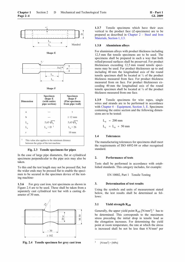
1.3.5 In the case of pipes, the tensile test may be performed on a sufficiently long section of the entire pipe. To enable the specimen to be secured in the test machine, mandrels have to be inserted into the pipe ends, cf. Figure 2.3, specimen shape E, or the pipe ends have to be pressed flat. Where the pipe diameter pre-cludes testing a length of the entire pipe, tensile speci-mens of shape F are to be taken from the pipe wall.
Where the wall thickness of the pipe is sufficient, cylindrical specimens as prescribed in 1.3.2 may also be used. The specimens shall then be taken from the sample in such a way that their axis is located at the mid-point of the wall thickness.
II - Part 1 GL 2009
Section 2 Mechanical and Technological Tests Chapter 1Page 2–3
D
�������� ��������� ���� � ����
�������� ���� ������ ������������������������ !�����������
� ��� �
( ��� ���#���
� �!)����*� �!)����*� ����+��
� ����#(
� ��� �����
��� ,����-��������������������������������������� �(������������������������������� ����'
� ����
� ����
.������
+
�
�
�
� (
�
Fig. 2.3 Tensile specimens for pipes
In the case of large pipe diameters, flat or cylindrical specimens perpendicular to the pipe axis may also be taken.
To this end the test length may not be pressed flat, but the wider ends may be pressed flat to enable the speci-men to be secured in the specimen device of the test-ing machine-
1.3.6 For grey cast iron, test specimens as shown in Figure 2.4 are to be used. These shall be taken from a separately cast cylindrical test bar with a casting di-ameter of 30 mm.
.�/�
#��0
1�/�
����#
#�
Fig. 2.4 Tensile specimen for grey cast iron
1.3.7 Tensile specimens which have their axes vertical to the product face (Z-specimens) are to be prepared as described in Chapter 2 – Steel and Iron Materials, Section 1, I.3.
1.3.8 Aluminium alloys
For aluminium alloys with product thickness including 12,5 mm flat tensile specimens are to be used. The specimens shall be prepared in such a way that both rolled/pressed surfaces shall be preserved. For product thicknesses exceeding 12,5 mm round tensile speci-mens may be used. For product thicknesses up to and including 40 mm the longitudinal axis of the round tensile specimen shall be located at ½ of the product thickness measured from face. For product thickness measured from on face. For product thicknesses ex-ceeding 40 mm the longitudinal axis of the round tensile specimen shall be located at ¼ of the product thickness measured from one face.
1.3.9 Tensile specimens for wire ropes, single wires and strands are to be performed in accordance with Chapter 4 – Equipment, Section 3, E. Specimens containing the entire section and the following dimen-sions are to be tested:
o
c o
L 200 mm
L L 50 mm
=
= +
1.4 Tolerances
The manufacturing tolerances for specimens shall meet the requirements of ISO 6892-84 or other recognised standard.
2. Performance of tests
Tests shall be performed in accordance with estab-lished standards. This category includes, for example:
EN 10002, Part 1 Tensile Testing
3. Determination of test results
Using the symbols and units of measurement stated below, the test results shall be determined as fol-lows:
3.1 Yield strength ReH
Generally, the upper yield point ReH [N/mm2] 1 has to be determined. This corresponds to the maximum stress preceding the initial drop in tensile load as the elongation increases. For determining the yield point at room temperature, the rate at which the stress is increased shall be not be less than 6 N/mm2 per
–––––––––––––– 1 [N/mm2] = [MPa]
Chapter 1 Page 2–4
Section 2 Mechanical and Technological Tests II - Part 1GL 2009
D

second and may not exceed 30 N/mm2 per second for steel. For non-ferrous metals the rate at which the stress is increased shall not be less than 2 N/mm2 per second and may not exceed 10N/mm2 per second. The test result shall be stated accurate to 1 N/mm2.
3.2 Proof stress Rp
In the case of materials without a marked yield point, the proof stress Rp [N/mm2] shall be determined. Gen-erally, the 0,2 % proof stress Rp 0,2 shall be specified. For austenitic steels as well as austenitc-ferritic (= duplex) steels, the 1 % proof stress Rp 1,0 may be stated instead of, or in addition to, Rp 0,2. The rate of loading and the indication of the results shall be as stated in 3.1.
3.3 Tensile strength Rm
In determining the tensile strength Rm [N/mm2], the rate of elongation, once the yield point or proof stress has been passed, shall not with ductile materials ex-ceed a maximum of 40 % per min.. With brittle mate-rials, e.g. grey cast iron, the rate of stress increase may not exceed 2,5 N/mm2 per second. The test result shall be stated accurate to 1 N/mm2.
3.4 Elongation A
It not otherwise stated, this relates to short propor-tional test specimens with Lo = 5,65 oS and then is named as A [%]. For test specimens whose gauge length bears a different relationship to the cross-section of the test specimen, the required elongation Ar shall comply either with the minimum values specified for the products in question (e.g. for a gauge length Lo = 200 mm), or with the minimum value calculated by applying the following formula:
2 5
or
o
SA 2 A
L
⎛ ⎞⎜ ⎟= ⋅ ⋅⎜ ⎟⎝ ⎠
This conversion formula may only be used for ferritic steels with a strength of ≤ 700 N/mm2 which have not been cold formed, cf. also ISO 2566.
The value for the elongation is valid if the distance of the fracture from the gauge marks is at least 1,25 times the diameter for round tensile specimens or at least the sum of the width and the thickness in the case of flat tensile specimens.
The result of the test shall be stated to an accuracy of 0,5 %. If the elongation is not determined using short proportional test specimens, then the gauge length [mm] shall be stated in the test certificate, e. g. A200 mm = elongation for initial gauge length Lo = 200 mm.
3.5 Reduction in area Z
The reduction in area at fracture Z [%] shall be deter-mined only where this is called for in the following sections of the Rules for Materials.
[ ]o u
o
S SZ 100 %
S⎛ ⎞−
= ⋅⎜ ⎟⎝ ⎠
The test result shall be stated to an accuracy of 1 %.
E. Notched Bar Impact Tests
1. General
1.1 As specified for the product in question, notched bar impact tests are to be performed either on Charpy V-notch specimens to ISO 148 (EN 10045 Part 1), or on Charpy U-notch specimens to ISO 83 (EN 10045 Part 1), see Figures 2.5 and 2.6.
1.2 Unless otherwise agreed, for products with a thickness of < 10 mm smaller dimension specimens with a specimen width of 7,5 or 5 mm are to be tested. In the case of products with thicknesses of < 6 mm, the notched bar impact test is generally not required.
The longitudinal axis of the notch shall be made per-pendicular to the surface of the product.
2. Dimensions of test specimens
Test specimens shall be machined to the dimensions shown in Figure 2.5 or 2.6 and those stated in Table 2.2.
The data given in Table 2.2 should be regarded as being the permitted tolerances for the specimen di-mensions.
�� �
�� �� ������
����
Fig. 2.5 Charpy V-notch specimen
��
#��
��
�
Fig. 2.6 Charpy U-notch specimen
II - Part 1 GL 2009
Section 2 Mechanical and Technological Tests Chapter 1Page 2–5
E

Table 2.2 Permitted tolerances of specimen dimensions
V-notch specimen U-notch specimen Dimensions
Normal size Tolerance Normal size Tolerance
Length of specimen Thickness of specimen
55 mm 10 mm
± 0,60 mm ± 0,06 mm
55 mm 10 mm
± 0,60 mm ± 0,11 mm
Width of specimen: – Normal specimen – Sub-size specimen – Sub-size specimen
10 mm 7,5 mm 5 mm
± 0,11 mm ± 0,11 mm ± 0,06 mm
10 mm –– ––
± 0,11 mm –– ––
Notch angle 45° ± 2° –– ––
Thickness at base of notch 8 mm ± 0,06 mm 5 mm ± 0,09 mm
Notch radius 0,25 mm ± 0,025 mm 1 mm ± 0,07 mm
Distance of notch centre from ends of specimen 1 27,5 mm ± 0,42 mm 27,5 mm ± 0,42 mm
Angle between plane of symmetry of notch and longitudinal axis
90° ± 2° 90° ± 2°
Angle between adjacent longitudinal faces 90° ± 2° 90° ± 2°
1 For pendulum impact testing machines which have automatic specimen positioning, a tolerance of ± 0,165 is recommended rather than ± 0,42.
3. Test machine
Wherever possible, use shall be made of a pendu-lum impact testing machine with an impact energy of 450 J or 300 J (in any case not less than 150 J) and an impact velocity of 5 to 5,5 m/s. The test ar-rangement is shown in Figure 2.7, with the character-istic quantities of the test machine being given in Table 2.3.
��
��
/�2
#���#!����
Fig. 2.7 Notched bar impact test
Table 2.3 Characteristic quantities of test machine
Dimension Requirement
Clear spacing between supports ( )0,2040 mm+
Radius of curvature of supports ( )0,501 mm+
Undercut of supports 11 1° ± °
Angle of peen wedge 30 1° ± °
Radius of curvature of peen cutter ( )0,5
02 mm+
Maximum thickness of pendulum face 18 mm
Striking velocity of pendulum 5 to 5,5 m/s 1
Angle between supports and bearing 90° ± 0,1°
1 For pendulum impact test machines built before 1983 a value of 4,5 to 7 m/s may be agreed.
Chapter 1 Page 2–6
Section 2 Mechanical and Technological Tests II - Part 1GL 2009
E

4. Performance of test
4.1 Impact tests using U-notch specimens should generally be performed at room temperature (23 ± 5) °C. Impact tests on V-notch specimens shall be performed at room temperature or at a lower test temperature, accord-ing to specification. With test temperatures below room temperature, the temperatures of the specimens are to be carefully checked. At the moment of fracture they may not vary from the prescribed test temperature by more than ± 2 °C. If the specimens are cooled by placing them in a bath, they shall remain there for at least ten minutes.
4.2 A test is regarded as being performed under normal conditions when the working capacity of the pendulum impact test machine is (300 ± 10) J and when a standard specimen is used. The following abbreviations are assigned to the notch impact energy value which is established under these conditions:
– KV for a V-notch specimen
– KU for a U-notch specimen
5. Determination of test results
5.1 Using the symbols shown below, the energy absorbed by the impact shall be normally stated in joules (J), accurately rounded to 1 J.
Where the test is conducted other than at room tem-perature, this shall also be stated.
5.2 If required, the crystalline proportion of the fracture surface and/or the lateral expansion at the point of fracture shall also be determined.
The crystalline proportion of the fracture surface shall then be estimated and expressed as a percentage of the total area of the fracture. The lateral expansion shall be measured to an accuracy of 0,01 mm on the side oppo-site the notch (cf. also DIN 50115 and ASTM A 370).
F. Technological Tests on Pipes
1. Pipe flattening test
1.1 To perform this test, a section of pipe equal in length to 1,5 times the pipe diameter, but not less than 10 mm and not more than 100 mm, is flattened between two plates to the prescribed distance H, see Chapter 2 – Steel and Iron Materials, Section 2, A.8.5 or until fracture occurs, see Figure 2.8. In the case of welded pipes, the specimen shall be placed in the press in such a manner that the seam is set at 90° to the direction of the pressure, unless agreed otherwise.
1.2 After the test, the specimens shall be thor-oughly examined for defects with normal visual acu-ity. The test shall be satisfactory if the specimen, hav-ing been flattened to the prescribed distance, is free from cracks and did not fracture.
(
��(3#
4
+�
Fig. 2.8 Pipe flattening test
The dimensions of the pipe section, the distance H between the flattening plates as well as the position of the welding joint are to be stated.
Examples of applicable standards:
EN 10233 Pipe Flattening Test or ISO 8492
2. Ring expanding test
2.1 To perform this test, sections of pipe measur-ing 10 to 16 mm in length L are expanded to the pre-scribed diameter C or until fracture occurs using a drift with a taper of about 1:5. Where necessary, more than one test shall be performed with drifts of increasing dia-meter. The superimposition of several specimens of the same size and steel grade is permitted, see Figure 2.9.
+��5
+����
*�� �����
6
7 +���
�
+
+��5���+���7
"��8�
Fig. 2.9 Ring expanding test
The intrusion rate of the mandrel may not exceed 30 mm/s.
C = Diameter after the the prescribed expansion
II - Part 1 GL 2009
Section 2 Mechanical and Technological Tests Chapter 1Page 2–7
F
The dimensions of the pipe sections, the outer diame-ter C of the expanded part of the pipe section or the relative expansion [%], as well as the ratio of the taper (if not 1:5) are to be stated.
Examples of standards to be applied:
EN 10236 Ring Expanding Test on Pipes or ISO 8495
2.2 After the test, the specimens shall be thor-oughly examined for defects with normal visual acu-ity, and the ductility of the pipes shall be assessed by reference to the expansion achieved and, where appli-cable, to the appearance of the fracture surface.
The test shall be satisfactory if the specimen reveals no unacceptable defects such as scabs, laps, cracks, grooves or laminations and if the prescribed expansion has been reached.
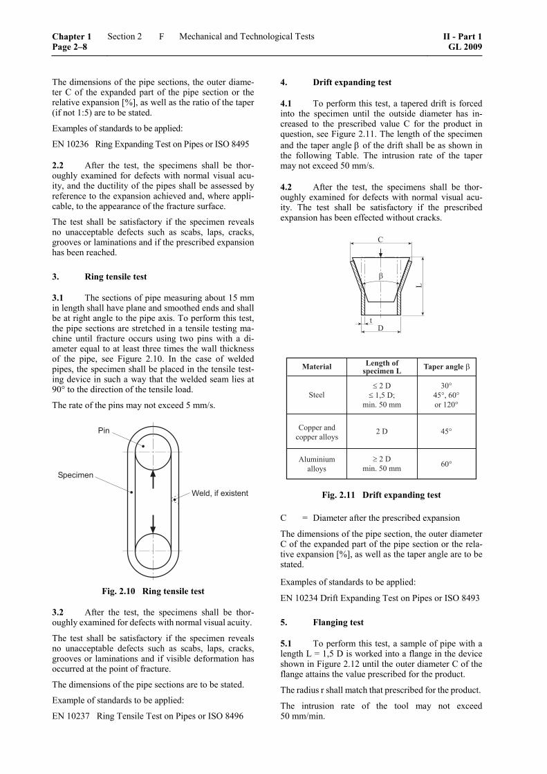
3. Ring tensile test
3.1 The sections of pipe measuring about 15 mm in length shall have plane and smoothed ends and shall be at right angle to the pipe axis. To perform this test, the pipe sections are stretched in a tensile testing ma-chine until fracture occurs using two pins with a di-ameter equal to at least three times the wall thickness of the pipe, see Figure 2.10. In the case of welded pipes, the specimen shall be placed in the tensile test-ing device in such a way that the welded seam lies at 90° to the direction of the tensile load.
The rate of the pins may not exceed 5 mm/s.
��
��������
����������������
Fig. 2.10 Ring tensile test
3.2 After the test, the specimens shall be thor-oughly examined for defects with normal visual acuity.
The test shall be satisfactory if the specimen reveals no unacceptable defects such as scabs, laps, cracks, grooves or laminations and if visible deformation has occurred at the point of fracture.
The dimensions of the pipe sections are to be stated.
Example of standards to be applied:
EN 10237 Ring Tensile Test on Pipes or ISO 8496
4. Drift expanding test
4.1 To perform this test, a tapered drift is forced into the specimen until the outside diameter has in-creased to the prescribed value C for the product in question, see Figure 2.11. The length of the specimen and the taper angle β of the drift shall be as shown in the following Table. The intrusion rate of the taper may not exceed 50 mm/s.
4.2 After the test, the specimens shall be thor-oughly examined for defects with normal visual acu-ity. The test shall be satisfactory if the prescribed expansion has been effected without cracks.
"������� #��$� �!��������# %������$���
*����
6��������� ����������9�
��#�+���!��+:���'������
/�2��2!�)�2����#�2
#�+ ��2
�������������9�
��#�+���'������ )�2
6
+�
�
Fig. 2.11 Drift expanding test
C = Diameter after the prescribed expansion
The dimensions of the pipe section, the outer diameter C of the expanded part of the pipe section or the rela-tive expansion [%], as well as the taper angle are to be stated.
Examples of standards to be applied:
EN 10234 Drift Expanding Test on Pipes or ISO 8493
5. Flanging test
5.1 To perform this test, a sample of pipe with a length L = 1,5 D is worked into a flange in the device shown in Figure 2.12 until the outer diameter C of the flange attains the value prescribed for the product.
The radius r shall match that prescribed for the product.
The intrusion rate of the tool may not exceed 50 mm/min.
Chapter 1 Page 2–8
Section 2 Mechanical and Technological Tests II - Part 1GL 2009
F

;����������
<�2
+�
=�������
+�#���+�#�
6
�
Fig. 2.12 Flanging test
5.2 The test shall be satisfactory if the flange has no apparent cracks. Minor defects on the edges can be disregarded.
The dimensions of the pipe section, the outer diameter C of the expanded part of the pipe section or the rela-tive expansion [%], as well as the edge radius of the forming tool r are to be stated.
Examples of standards to be applied:
EN 10235 Flanging Test on Pipes or ISO 8494
G. Instructions for the Bend Test, Hardness Test and Drop Weight Test
1. Technological bend test
1.1 For this test, specimens with thickness a and width b are to be prepared, the edges of which may be rounded on the tension side to a radius of 1 – 2 mm. For plates and sections the specimen thickness a is equal to the product thickness t. For product thick-
nesses t exceeding 25 mm the thickness may be re-duced by machining the compression side of the bend specimen to not less than 25 mm.
For product widths smaller than or equal to 30 mm the specimen width b shall be equal to the product width. For product widths exceeding 30 mm the specimen width b = 30 – 50 mm.
For forgings, castings and semi-finished products the specimen thickness shall be a = 20 mm and the speci-men width b = 25 mm.
1.2 For butt-welded joints the bend specimens at right angle to the weld joint shall have the following dimensions for verification of the final pass and the root pass:
– a = t
– b = 30 – 50 mm
For side bend specimens the following dimensions do apply:
– a = 10 mm
– b = t
For t ≥ 40 mm the side bend specimen may be split, with the width of each part being at least 20 mm.
For bend specimens with longitudinal direction to the joint the dimensions shall be in accordance with gen-erally accepted standards.
�� +���/�� ��
�+3#
&��������������
��������������
�
(
Fig. 2.13 Technological bend test
II - Part 1 GL 2009
Section 2 Mechanical and Technological Tests Chapter 1Page 2–9
G

1.3 To perform this test, the test specimen is bent in a continuous operation as shown in Figure 2.13 and using a mandrel of specified radius D/2 until the pre-scribed bending angle α is reached or the initial in-cipient fracture occurs. For normal strength steels D/2 = 2 ⋅ a, for higher strength steels D/2 = 3 ⋅ a. The test shall be satisfactory if the prescribed bending angle is achieved without incipient fracture. If, when the specimen is unclamped, it springs back, the bend-ing operation need not be repeated.
Example of standard to be applied:
ISO 7438 Metallic materials - Bend Test
2. Hardness tests
2.1 The tests are to be performed, according to specification, to determine the Brinell, Vickers or Rockwell hardness using standardized methods, see for example:
ISO 6506 Brinell Hardness Test
ISO 6507 Vickers Hardness Test
ISO 6508 Rockwell Hardness Test
2.2 Hardness tests shall not be considered a substi-tute for the tensile test. Brinell hardness tests may, how-ever, be permitted for the purpose of comparing me-chanical properties provided that, of several products of the same shape, grade of material and heat treatment, at least one has been subjected to the tensile test.
3. Pellini drop weight test
3.1 This test shall be performed in accordance with Stahl-Eisen-Prüfblatt 1325 (Iron and Steel Test Specification 1325), EN 10274, or ASTM-E208 on steels with product thicknesses of ≥ 16 mm. The specimen shape will be chosen which most closely matches the product thickness accordingly to Table 2.4.
Table 2.4 Specimen dimensions for drop weight test
Specimen shape Dimensions [mm]
P1 P2 P3
360 × 90 × 25 130 × 50 × 19 130 × 50 × 16
The correct specimen thickness shall be achieved by machining one side.
The long sides of the test specimens shall be made with a saw cut or, in the case of specimens obtained by thermal cutting, shall be machined with a machin-ing allowance of at least 25 mm.
3.2 At least 2 test specimens shall be prepared from the sample. The position of the longitudinal axis
of the specimens in relation to the main direction of deformation of the product is optional, but shall be the same for the set of specimens. Where the testing is performed by heats, specimens shall be taken from the thickest product.
3.3 Specimens shall be tested at the specified test temperature. The test shall be considered satisfactory if neither of the two specimens is fractured or if incipient cracks starting from the weld bead terminate in the parent metal and do not extend to one or both edges.
Where one or both specimens fail to satisfy the afore-mentioned conditions, a retest may be carried out in accordance with H.4.
3.4 Where drop weight tests are to be performed on products other than those specified in 3.1 or as part of approval tests, the scope of the test shall be spe-cially agreed with GL.
H. Retests
1. General
1.1 If the test sections or specimens specified for a test are not properly taken and prepared, the test results obtained with them shall be invalid. The tests shall then be repeated on properly prepared test specimens.
1.2 If, in a properly performed test, the require-ments are not met, then, before the corresponding unit test quantities are rejected, retests may be carried out subject to the conditions stated below. Retests are not allowed if it is suspected that the wrong material is concerned.
1.3 If the unsatisfactory result of a test is due to obvious defects in the execution of the test or to a nar-rowly defined fault in the test specimen, the result shall be disregarded and the test in question shall be repeated on a test specimen of the same type which shall be taken from the same test section. This also applies to tensile specimens which, when tested, fracture outside the valid measuring length as defined in D.3.4.
1.4 If the unsatisfactory result of a test is attribut-able to improper heat treatment of the products, they may be resubjected to heat treatment. Subsequently the entire test shall be repeated, and the original test result shall be disregarded.
1.5 The manufacturer may also follow the proce-dure described in 1.4 in the case of those products which, according to the specifications, may be sup-plied without heat treatment but which have failed to meet the requirements in this condition.
1.6 If, under test, a large proportion of the prod-ucts fails because of constantly recurring manufactur-ing defects, the entire delivery may be rejected.
Chapter 1 Page 2–10
Section 2 Mechanical and Technological Tests II - Part 1GL 2009
H
2. Unsatisfactory tensile test specimens (ex-cluding pipes)
2.1 Individual tests
For each unsatisfactory tensile specimen, two substi-tute specimens shall be tested, which shall be taken from the same test section as the original specimen, or from the same sample. In every case, both specimens shall satisfy the requirements.
2.2 Testing by heats or batches
The manufacturer shall have the option of separating the sample which has yielded unsatisfactory results or of continuing to treat it as part of the unit test quantity.
If the sample in question is separated, then, for each unsatisfactory tensile specimen, two substitute speci-mens shall be tested which shall be taken from differ-ent samples of the unit test quantity.
If the sample in question continues to be treated as part of the unit test quantity, one of the retests shall be performed on this sample and the other on a different sample.
Both retests shall satisfy the requirements.
3. Unsatisfactory impact test specimens (ex-cluding pipes)
3.1 Individual tests
If the average value of 3 impact test specimens fails to satisfy the requirements or if a single value is less than 70 % of the stipulated average value, 3 substitute specimens shall be taken from the same test section and tested. The average value of the 6 individual tests shall then meet the requirements. However, of the 6 individual values only 2 may be below the required average value, of which only one individual value may be less than 70 % of the prescribed average value, failing which the sample in question shall be rejected.
3.2 Testing by heats or batches
If the average value of 3 impact test specimens fails to satisfy the requirements or if a single value is less than 70 % of the stipulated average value, then the procedure described in 3.1 shall be applied initially.
If the retest also produces an unsatisfactory result, the sample tested shall be rejected and two further sam-ples, of the same or the next smaller thickness, from the same unit test quantity shall be tested.
If, again, one of the samples fails to satisfy the re-quirements, then the entire unit test quantity shall be
rejected. With the consent of the Surveyor, the re-maining sample quantities in the unit test quantity may, however, be subjected to testing piece by piece.
4. Unsatisfactory drop weight test specimens
4.1 Individual tests
If one or both of the two test specimens fail(s), two similar substitute specimens may be taken from the same sample and tested. Both substitute specimens shall satisfy the requirements. If they fail to do so, the relevant sample shall be rejected.
4.2 Testing by heats
If one or both of the two test specimens to be taken from the thickest sample of the heat fail(s), then, from the same sample and from a different sample of the same thickness - or, if not available, from the next smaller thickness - two specimens of the same type each shall be taken and tested. All four specimens shall satisfy the requirements. If they fail to do so, then the relevant heat shall be rejected.
With the consent of the Surveyor, the remaining sam-ple quantities in the rejected heat may, however, be subjected to individual testing.
5. Unsatisfactory results in the testing of pipes
5.1 Testing by batches
If, when subjected to the tensile test, the ring test or the notched bar impact test, pipes fail to satisfy the requirements, the test which has produced the unsatis-factory results shall be repeated on the same end of the pipe selected for the test. If the new test fails to satisfy the requirements, the pipe in question shall be dis-carded. In its place two further pipes shall be taken from the batch concerned and shall be subjected to the full range of tests. If, during testing, one of the re-quirements is not met, then the entire batch shall be deemed unacceptable.
However, with the consent of the Surveyor, the char-acteristic which failed to meet the requirements may be checked on each individual pipe.
6. Retesting specified in standards
Where a national or international standard specifies a wider scope for the performance of repeat tests; this shall take precedence over the retests described in 5.1.
II - Part 1 GL 2009
Section 2 Mechanical and Technological Tests Chapter 1Page 2–11
H


Section 3
Non-Destructive Testings
A. General Items
1. This Section contains general Rules applica-ble to the performance of non-destructive tests at semi-finished products and components intended for the installation in ships classed with GL.
2. Type and scope of the non-destructive testings prescribed for the individual products are stated in the appropriate sections.
B. Standards and Regulations
1. The standards and regulations indicated in the specific sections are integral part of these Rules and have to be observed when performing the non-destructive testing.
2. Testings according to other comparable stan-dards or regulations require prior consent of GL. For this they shall be submitted to GL for assessment and approval before starting the testing.
3. The manufacturer or purchaser shall state all details of the testing in a testing instruction or specifi-cation and deliver it to the GL-Surveyor before start-ing the testing.
C. Requirements Applicable to the Inspection Body
1. For performing non-destructive testings the manufacturer shall set up a qualified inspection body which is independent of the manufacturing depart-ments and part of a manufacturing site certified ac-cording to ISO 9001, or which is accredited according to ISO/IEC 17025.
2. The inspection body shall have available the necessary regulations, testing specifications, testing equipment, accessories and, if required, comparators for the surface finish of castings.
3. If the manufacturer has no inspection body available, he shall demonstrate which external inspec-tion body will perform the testings on his behalf if necessary.
This external inspection body shall be accredited ac-cording to ISO/IEC 17025 or shall be part of a manu-facturing site certified according to ISO 9001.
D. Inspection Personnel, Supervisors
1. Inspection personnel
1.1 The inspection personnel charged with the non-destructive testing shall be familiar with the test method concerned and shall be qualified and certified to EN 473.
1.2 For the evaluation of results of non-destructive tests only such inspection personnel shall be charged that holds level-2 certificates for the test method concerned which were issued:
– by an independent certification authority accord-ing to EN 473 or ISO 9712
– by the employer of the inspection personnel according to ASNT "Recommended Practice No. SNT-TC-1A"
2. Inspection supervisors
For scheduling and monitoring the testings and for evaluating the results an inspection supervisor quali-fied at least according to 1.2 shall be available.
The inspection supervisor shall hold as far as possible a level-3 certificate for the test method concerned according to the Rules indicated in 1.2.
E. Test Methods, Equipment and Test Media
1. Test methods
For detecting surface and/or volumetric discontinuities in the components indicated in A.1. the test methods from Table 3.1 or combinations of them shall be em-ployed in dependence of the material, the geometry of the component, the expected service condition and the possible flaw position.
II - Part 1 GL 2009
Section 3 Non-Destructive Testings Chapter 1Page 3–1
E
Table 3.1 Test methods
Testing of Method Short name 1
Visual testing VT
Magnetic particle testing MT
Eddy current testing ET external
condition
Penetrant testing PT
Ultrasonic testing UT
Radiographic testing RT internal condition
Leakage testing LT 1 Definition according to DIN EN 473.
2. Equipment and test media
2.1 The equipment and test media used shall conform to the state of art and the relevant standards and shall be in perfect, serviceable condition.
The Surveyor shall be presented by request proof of internal and/or external monitoring of the equipment and the test media.
2.2 If testing facilities, equipment and inspection personnel of external inspection bodies are engaged the workshop in question has to ensure that the condi-tions according to C. and D. are fulfilled.
F. Preparation and Performance of Tests
1. Preparation of tests
The surfaces that will be tested shall be free of rem-nants of the moulding material, scale, grease, dirt, protective coatings and other contaminations which may affect the indication sensitivity of the specific test methods.
2. Performance of tests
2.1 As a rule the prescribed tests shall be per-formed by the inspection personnel of the inspection body of the manufacturer or of the external body charged with the inspection.
The specific components that will be tested shall be subjected to the Surveyor in final machined condition for the visual testing.
2.2 In case ultrasonic (UT) and or surface crack detecting (MT, PT) shall be performed by the GL Surveyor a special agreement is required.
2.3 The Surveyor shall be informed by the manu-facturer of the works performing the further process-ing about the planned non-destructive testings in time. He will attend the testings in his discretion.
G. Certification of Test Results
1. Inspection reports shall be prepared on all performed tests, and these shall be submitted to the Surveyor together with the further documentation (e. g. NDT plans, film position plans, radiographs).
The inspection reports shall contain all the necessary details according to I. to L. relating to the particular test method used, the position at which the test was performed and the results obtained.
2. The inspection department shall attest the test results by means of inspection certificate according to EN 10204-3.1.
H. Visual Testing (VT)
1. The surfaces of the components that shall be subjected to testing shall be at least in the condition specified in F.1. or in the final machined condition.
2. Of the components that shall be tested the entire surfaces shall be visually tested. In doing so internal surfaces such as e.g. bore holes shall be in-cluded in the tests.
3. For performing visual testing optical magni-fying devices, endoscopes or surface comparators shall be employed if necessary.
Specifications concerning testing criteria are contained in the appropriate specific sections of Chapter 2 to 5.
4. The manufacturer or the company performing further processing shall arrange that testing can be performed with adequate illumination.
The viewing conditions shall be in accordance with the requirements of ISO 3059 or EN 13018.
Light and surface reflections shall be avoided by ap-propriate means.
Chapter 1 Page 3–2
Section 3 Non-Destructive Testings II - Part 1GL 2009
H
I. Magnetic Particle Testing (MT)
1. Magnetization equipment and method
1.1 The surfaces of the components that shall be subjected to testing shall be at least in the condition specified in F.1. or in the final machined condition.
1.2 The stationary or portable equipment for magnetic particle testing shall be in accordance with the state of art for testing and with the standards ISO 9934-1, ISO 9934-2 and ISO 9934-3 or with other standards which are equivalent to these standards.
1.3 The choice of the method of magnetization and of the current for magnetization depends on the geometry of the component and on the type of surface defect to be detected (cracks, inclusions that are lying open towards the surface or inclusions close towards the surface).
1.4 If possible, magnetization shall be effected by passing a current through the workpiece and/or by yoke magnetization using alternating or direct current.
1.5 Where a current is passed through the work-piece, alternating, direct, impulse or surge current may be used. A combination of the aforementioned methods for the detection of variously orientated defects is allowed.
2. Test media
2.1 Suspensions consisting of a carrier liquid (test oils or water with inhibitors) and dispersed mag-netic particles (black or fluorescent) shall be used as test media.
Only such test media shall be used that conform to the requirements of ISO 9934-2.
2.2 Before magnetic particle testing is com-menced the inspector shall verify the test media by means of suitable reference blocks according to ISO 9934-2 and shall prove this to the Surveyor by request.
Note
– Reference blocks 1 and 2 according to ISO 9934-2
– JIS-test block according to JIS Z 2343
3. Performance of magnetic particle testing
3.1 Manual testing
In order to reveal variously orientated defects the magnetization shall be effected in a crosswise manner in two different directions. The angle of the both di-rections for magnetization should be in the range from 60° to 90°. The magnetizing field strength (effective tangential field strength) should be at least 2 kA/m but should not exceed 6 kA/m.
3.2 Mechanized testing
When mechanized testing is performed the conditions stated in 3.1 shall be provided by an adequate choice or combination of magnetization currents and meth-ods.
3.3 When burn marks on final machined surfaces have to be avoided then for the magnetization by means of prods with alternating current only fusible supply electrodes made of tin-aluminium alloys shall be employed.
3.4 Testing of machinery components in the final machined condition shall preferably be performed by stationary appliances. The appliances for magnetizing employed for this shall fulfil the requirements of ISO 9934-3 or another equivalent standard. On demand of the Surveyor the parameters of magnetization stated in 3.1 shall be proved by the manufacturer by means of measurement of the effective tangential field strength or by means of "Berthold" test blocks.
4. Applying of test media, magnetization
The suspension containing the magnetic particles shall be applied on the surface to be tested by spraying or wetting. When doing so the magnetization shall last at least that long as the surface to be tested is sprayed with the magnetic particle suspension; subsequently magnetization shall be performed (at least 5 seconds) until no movement of the magnetic particle suspension can be detected. Testing when remanence is present (residual magnetism in the component) is not allowed.
5. Illumination of testing surfaces
In order to obtain an adequate contrast of test surface and indication the following requirements according to ISO 3059 for the light intensity and the UV inten-sity shall be fulfilled and shall be proved on the test surface with adequate and verified measuring devices, e.g. luxmeter or UV intensity meter.
The UV intensity on the test surface shall be not less than 10 W/m2, the maximum ambient light intensity shall be 20 Lux.
6. Certification of testing results
The manufacturer or the inspection body charged by him shall issue a certificate concerning the performed magnetic particle test containing at least the following information:
– name and address of the inspection body (for external inspection bodies)
– details concerning the accreditation or the ap-proval of the inspection body
– testing specification to be applied and/or testing instructions
II - Part 1 GL 2009
Section 3 Non-Destructive Testings Chapter 1Page 3–3
I
– details of the component such as:
– order no.
– material designation
– heat no.
– specimen no.
– machining condition
– surface condition
– testing scope, inspection zones, severity levels
– type of magnetization, e.g. according to ISO 9934-3
– test equipment, test media, test blocks
– proof of the magnetization by means of meas-urement of the effective tangential field strength
– declaration of the inspection zones and accep-tance criteria
– time of testing
– evaluation of test results
– place and date of testing
– name of the inspector, the inspection supervisor and their qualifications
The aforementioned details may also be certified by means of works instructions of the manufacturer.
They above and the test certificate shall be submitted to the Surveyor together for assessment and acknowl-edgement.
Specifications for the aforementioned acceptance and assessment criteria are contained in the appropriate specific sections of Chapter 2 to 5.
J. Penetrant Testing
1. Testing is to be performed with a testing agent system consisting of penetrant remover, pene-trant and developer in accordance with EN 571-1 or other recognized standards. The employed equipment for this shall fulfil the criteria of ISO 3452-4.
2. Test media and their verification
2.1 The testing agent system required for pene-trant testing shall fulfil the requirements of ISO 3452-4 or of another recognized standard.
2.2 Before penetrant testing is commenced the suitability of the testing agent system is to be verified by means of test blocks e.g. according to ISO 3452-4 and is to be proven on demand to the Surveyor.
3. Performing penetrant testing
3.1 Before testing is commenced the manufac-turer or orderer shall submit to the Surveyor test in-structions fulfilling at least the requirements listed in the following.
3.2 Pre cleaning of test surface
The surface to be tested shall correspond to the re-quirements specified in F.1. and shall be cleaned com-pletely with a cleaner adequate for the testing agent system before testing is commenced.
Specifications concerning the surface areas for which testing is required are contained in the appropriate specific sections of Chapter 2 to 5.
3.3 Testing temperature
As a rule the temperature of the surfaces to be tested shall be between + 5 °C and + 50 °C. For lower tem-peratures pre heating of the test area shall be per-formed on an extensive surface by which the test area achieves the permitted temperature range from + 5 °C and + 50 °C.
3.4 Applying the penetrant
The penetrant may be applied by spraying, brushing or electrostatic spraying depending on the shape and size of the surface or of the geometry of the component to be tested. The test surface shall be completely wetted throughout the entire penetration time.
3.5 Penetration time
The penetration time depends on the properties of the penetrant, testing temperature, the material of the component to be tested and the type of discontinuities that are to be detected and should last from 5 to 60 minutes.
3.6 Intermediate cleaning
Following penetration, the surplus penetrant shall be completely removed in an appropriate manner from the test surface in such a way as to leave behind the penetrant lodged in any defects present.
3.7 Developing process
The developer is to be applied evenly and as thinly as possible immediately after intermediate cleaning and drying. The test surface should just be completely covered.
The developing time should be at least of the same as the time allowed for penetration.
The evaluation of the indications shall not start before the developing time has expired.
Chapter 1 Page 3–4
Section 3 Non-Destructive Testings II - Part 1GL 2009
J

4. Illumination of the test surfaces
The test surfaces shall be illuminated adequately and reflection of light from already machined surfaces are to be avoided.
Precondition for an adequate evaluation of the indica-tions are the requirements for illumination specified in I.5.
5. Testing criteria, evaluation of indications
Discontinuities exceeding the prescribed acceptance criteria by size and quantity as well as cracks of every type are not permitted.
Specifications for the evaluation of indications are contained in the appropriate specific sections of Chap-ter 2 to 5.
6. Cleaning of the test surfaces
After completion of penetrant testing any residuals of the test media shall be removed of the test surfaces. For this a cleaning agent shall be used that corre-sponds to the prior employed testing agent system and which will not have any effect on the further process-ing of the component.
7. Certification of test results
The manufacturer or the inspection body charged by him shall issue a certificate concerning the performed penetrant test containing at least the following infor-mation:
– name and address of the inspection body (for external inspection bodies)
– details concerning the accreditation or the ap-proval of the inspection body
– testing specification to be applied and/or testing instructions
– details of the component such as: – order no. – material designation – heat no. – specimen no. – machining condition
– surface condition
– testing scope, testing areas, severity levels
– employed testing agent systems according to EN 571-1, test blocks according to ISO 3452-3
– declaration of the inspection zones and accep-tance criteria
– time of testing
– evaluation of test results
– place and date of testing
– name of the inspector, the inspection supervisor and their qualifications
The aforementioned details may also be certified by means of works instructions of the manufacturer.
They and the test certificate shall be submitted to the Surveyor together for assessment and acknowledge-ment.
K. Ultrasonic Testing (UT)
1. Methods
1.1 Ultrasonic testing is to be performed with the impulse echo technique in accordance with recognized standards. Such are e.g. EN 12223, EN 27963, EN 12668-3, EN 583-1, EN 10228-3, EN 10160 and EN 12680-1.
Other national or international standards may be ap-plied if they provide an equivalent method.
1.2 The methods described here relate to the testing of components and machinery constructions made of ferritic steels. For testing of components made of austenitic or austenitic-ferritic steels special agreements are to be made.
1.3 Alternatively ultrasonic testing may be per-formed according to the test instructions of the manu-facturer or of the orderer on condition that an equiva-lent test can be achieved.
2. Test specification
2.1 The manufacturer or the orderer shall prepare a test specification which shall contain at least the following information:
– state of machining for pre and final testing
– test method, type of test equipment, type of probes, testing frequencies
– calibration of equipment
– surface condition depending on the manufactur-ing stage, surface roughness (if necessary)
– position of incidences, if necessary explained by means of sketches
– heat treatment condition depending on the manufacturing stage
– determination of testing areas in accordance with the requirements specified in Chapter 2 – Steel and Iron Materials, Section 3 or 4
– evaluation criteria for the specific testing areas and severity levels, respectively
– indication of other applicable standards and regulations
II - Part 1 GL 2009
Section 3 Non-Destructive Testings Chapter 1Page 3–5
K

3. Test appliances and accessories
Ultrasonic testing appliances and probes shall comply with the state of the art and with recognized stan-dards 1 and shall fulfil at least the following require-ments:
3.1 Requirements for the test equipment
– The ranges of adjustment shall enable the range of at least 20 mm up to 2 m without any inter-vening gap for longitudinal and transverse waves in steel.
– The amplification shall be adjustable for a range up to at least 80 dB with switching stages of 2 dB, the accuracy shall be 1 dB.
– The linearity of the time sweep and the vertical linearity shall be better than 5 % of the adjust-ment range or of the screen.
– The test equipment shall be applicable for probes from 1 to 6 MHz nominal frequency for impulse echo technique with straight or SE (twin transducer) probes.
3.2 Requirements for the probes
3.2.1 The selection of the probes concerning the nominal frequency and the transducer size depends on the size of the disc-shaped reflector to be detected, the sound path travel distance and the sound attenuation of the material to be tested.
3.2.2 Depending on the geometry of the component and the type and position of discontinuity to be de-tected straight beam probes and/or angle probes are to be employed; for testing of regions close to the surface SE straight beam probes shall be employed.
3.2.3 For oblique scanning probes with angle of incidence between 35° and 70° shall be employed. Their nominal frequency shall be between 1 and 6 MHz.
4. Calibration blocks
For verification of the inspection system calibration blocks type 1 according to DIN EN 12223 and calibra-tion blocks type 2 according to DIN EN 27963 or other adequate calibration blocks with reference re-flectors are to be used.
5. Coupling media
For inspection the oils, greases or other adequate cou-pling media recommended by the manufacturer of the equipment shall be used preferably.
For calibration of the equipment the same coupling medium shall be used.
–––––––––––––– 1 Recognized standards are e.g. EN 12668-1, EN 12668-2 and
EN 12668-3.
6. Performing ultrasonic testing
Ultrasonic testing of machinery parts is to be per-formed in accordance with the method, standards and regulations specified in 1.1 and/or according to speci-fications of the manufacturer or the orderer.
6.1 Calibration of the inspection system
6.1.1 Calibration of the distance
The calibration of the distance is to be performed at the calibration block type 1 in accordance with EN 12223 or at the component.
The inspection range shall be selected in such a way that the back wall echo of the component thickness to be tested will appear at 80 % of the screen width.
6.1.2 Calibration of sensitivity
Calibration of sensitivity shall be adjusted in such a way that indications to be registered are not smaller than 2/5 of the screen height at the end of the inspec-tion range.
The signal-to-noise ratio based on the registration level shall be at least 6 dB.
Deviations of these specifications may be agreed on by the orderer and/or manufacturer and GL in techni-cally justified exceptional cases.
6.2 Scanning of the test area and testing veloc-ity
6.2.1 Scanning of the test area
In case scanning of test surfaces without any interven-ing gap is required, e.g. in case of 100 % volumetric inspection, the test paths shall overlay each other with at least 15 %.
6.2.2 Testing velocity
If ultrasonic testing is performed manually then with regard to optimal localisation of the indications the testing velocity shall not exceed 100 mm/s.
7. Evaluation of indications
7.1 Indications without extension
The evaluation of indications without extension is to be performed according to the AVG-method (=DGS method = distance gain size method). In doing so the reference reflector size shall be specified as diameter of the equivalent disc shaped reflector (KSR) [mm].
7.2 Indication with extension
If not otherwise agreed, the determination of the re-flector extension shall be performed according to the half-amplitude technique.
Chapter 1 Page 3–6
Section 3 Non-Destructive Testings II - Part 1GL 2009
K

Specifications concerning the afore mentioned evalua-tion and acceptance criteria are contained in Section 3, G. and Section 4, G. of Chapter 2 – Steel and Iron Materials.
8. Certification of test results
The manufacturer or the inspection body charged by him shall compile a report concerning the test which shall contain at least the following information:
– name and address of the inspection body (for external inspection bodies)
– details concerning the accreditation or the ap-proval of the inspection body
– testing standards to be applied and/or testing specifications
– details of the component such as: – material – dimensions – component no. – heat no. – drawing no. – condition of supply
– time of testing, testing scope, inspection zones, severity levels
– the manufacturer and type of the employed testing equipment
– manufacturer, type, nominal frequency and angle of incidence of the employed probes
– type of calibration of distance and sensitivity
– specifications concerning the suitability for ultrasonic testing, surface preparation, correc-tion, values (transfer correction and sound at-tenuation) coupling media
– description of the position of reflectors to be recorded by means of sketches, the size of KSR, its extension in length, width and depth as well as the back-wall echo attenuation
– place and date of testing
– name of the inspector, the inspection supervisor and their qualifications
L. Radiographic Testing
1. Method
1.1 If necessary radiographic testing is to be performed in addition to ultrasonic testing in case doubts exist concerning the evaluation of indications of ultrasonic testing.
Radiographic testing can be performed depending on the type of the component to be inspected, its material grade and wall thickness, either with x-rays or gamma rays.
1.2 As a rule radiographic testing is to be per-formed in accordance with recognized standards such as EN 444, EN 1435 for the radiographic examination of welded joints or EN 12681 for the testing of cast components.
2. Scope of validity
The following specifications apply for radiographic testing of components indicated in Chapter 2 – Steel and Iron Materials, Section 4.
3. Performing radiographic testing
As a rule radiographic testing is to be performed in accordance with EN 12681, test category A. Thereby the image quality category A according to EN 462-3 shall be fulfilled.
Testing in accordance with other national or interna-tional standards may be agreed on with GL on condi-tion that the conditions of the standards indicated in 1.2 will be fulfilled.
4. Testing specification
4.1 The orderer or the manufacturer shall prepare a testing specification which shall contain the test method and all relevant details. Especially the follow-ing information shall be specified:
– radiation source, focal spot size or dimensions of the employed gamma-ray source
– radiation energy
– film system class and screens
– test category
– thickness range to be penetrated
– type and position of the image quality indicator
– distances between the film and the focal point
– image quality, density
– test arrangement explained by means of sketches or drawings
4.2 For cast components where a large amount of radiographing is required the manufacturer shall pre-pare a film position plan.
The specification as well as the film position plan shall be submitted to GL for evaluation.
5. Selection of radiation source
The selection of the radiation source depends on the thickness ω of the tested component to be penetrated, the required test category and the selected radio-graphic arrangement according to EN 12681.
II - Part 1 GL 2009
Section 3 Non-Destructive Testings Chapter 1Page 3–7
L

6. Selection of film system and intensifying screens
6.1 The selection of the film class depends on the test category and the thickness to be penetrated. The selection of the intensifying screens depends on the maximum permissible tube voltage of the X-rays or the type of isotopes, see Table 3.2. In case intensifying screens are used close contact between film and screen has to be ensured.
6.2 For the selection of the film class EN 444 is to be observed. A comparison of comparable interna-tional standards for film system classes is contained in Table 3.3.
7. Film density
7.1 The parameters for the exposure shall be selected in such a way that in the entire region to be evaluated the density S of the radiographs according to EN 444 is larger than S ≥ 2,0 for test category A and larger than S ≥ 2,3 for test category B. Reduction of the minimum required density to 1,5 for test category A or to 2,0 for test category B is only permitted on condition that an appropriate agreement between the orderer and the manufacturer is made and that the multiple film technique is employed. This agreement is to be submitted to GL.
7.2 The upper limit for density depends on the brightness of the film illuminator which is employed for the evaluation.
7.3 In order to depict different wall thickness regimes of cast components without loss of quality within the density limits specified in 7.1 on one screen, the procedures for multiple film technique as indicated in EN 12681 shall be employed.
7.4 For evaluation of radiographs the density shall be verified with a densitometer.
8. Verification of image quality
8.1 The image quality is to be verified by means of image quality indicators such as e.g. wire indicators in accordance with EN 462-1. In case image quality indicators cannot be positioned conforming to standards, i.e. away from the film, the image quality value shall be verified at least once by means of comparative radiographs prepared under the corresponding conditions.
8.2 In general, for steel castings of test category A, the image quality class A and for test category B the image quality class B according to EN 462-3 shall be achieved.
9. Evaluation of radiographs, evaluation criteria
The inspection department shall submit to the Sur-veyor for evaluation all radiographs and evaluation reports prepared by the inspector. It is up to the Sur-veyor to evaluate all radiographs or only a specific number of them.
The radiographs evaluated by him are to be stamped by him.
The testing and acceptance criteria applicable for the evaluation of the radiographs are contained in Chapter 2 – Steel and Iron Materials, Section 4, G.9.
10. Certification of the test results
The manufacturer shall compile a report concerning the evaluation of the radiographs which shall contain at least the following information:
– name and address of the inspection body (for external inspection bodies)
– details concerning the accreditation or the ap-proval of the inspection body
– details of the cast component such as:
– material
– heat no.
– pattern no.
– drawing no.
– condition of supply
– number and name of the testing specification
– testing standards to be applied and regulations
– method of radiographing and test categories
– film position plans, method of marking
– type of radiation source: tube/isotope, size of focal spot or of the radiation source, respectively
– tube voltage and anode current or activity of the radiation source
– exposure time and distance between radiation source and film
– selected film systems, screens and filters
– type and position of image quality indicator
– film density
– place and date of testing
– name of the inspector, the inspection supervisor and their qualifications
Chapter 1 Page 3–8
Section 3 Non-Destructive Testings II - Part 1GL 2009
L

Table 3.2 Film System classes and metal screens in accordance with EN 444 and EN 12681
������������� ��������������������
����������������
������
������
���������� ������������������
������
������
�������� �������������
�������� ����������������������
� ������� ��� ����������������� �����������������
�� ��� ����������������� ������������������
�������� ���������������� ����� �� ��� ����������������� ��������� ����������
!�
!�
!"
#$��%&
'���(�
��)�����
��������
� ������� ��� ����������������� �����������������
�� ��� ����������������� ��������� ����������
!�
!"
�������� ������� ��������������
���������
���������
�� ������������ ��������� ����� ���
�� ������������ �������������� ����
*�������������� ��������� ����� ���!�
+���& !� !"�� ������������ �������� �� �� ���
�� ������������ ������������� ����
!�%�����������
��,�������!�
!"
!�
�� ��� ������������ ��������������������� ������(�����
�������-���� ��.��/� ��0�������1�����"�1��
����������
����������
!�
!�
�� ��� ������������ ��������������������� ������(�����!�
�������-���� ��.��/� ��0�����"�1������ �1��
����������
�������)�����������
��,�������
�� ������� ������������������� ��������������������"
*��������� ������������������������������ ���� ����������������������"
!�
!"
!"
!�
�������-���� ��.��/� ��0���$2�� �1��
����������
�������)�����������
��,�������!�
!"
!�
!" �� ������� ������ ���������������������
������������ �
�� ������� ������ ���������������������
*��������� ������ ���������������������
� ����������������������/�0/���-�����������$���������� ���������0���$���/���� ����������.��/��� ������� �����������������������$����������� ������� ��������������������� ����������$��.�� ��/���� � �� ��$���������� ���/������� ���������3������������������������� ������$����������" ���������3����������������������� ������$�����������0����� �$���/��� ������ 0���� ������ '� 0��� ������ ������$�����������0����� �
!"
!�
!"
4��(� ��,����� !� !" �� ��� ����������������� �������������� ���
*�������������� ��������� ����� ���
II - Part 1 GL 2009
Section 3 Non-Destructive Testings Chapter 1Page 3–9
L
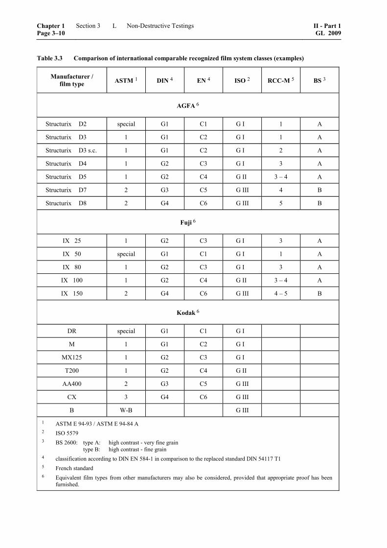
Table 3.3 Comparison of international comparable recognized film system classes (examples)
Manufacturer / film type ASTM 1 DIN 4 EN 4 ISO 2 RCC-M 5 BS 3
AGFA 6
Structurix D2 special G1 C1 G I 1 A
Structurix D3 1 G1 C2 G I 1 A
Structurix D3 s.c. 1 G1 C2 G I 2 A
Structurix D4 1 G2 C3 G I 3 A
Structurix D5 1 G2 C4 G II 3 – 4 A
Structurix D7 2 G3 C5 G III 4 B
Structurix D8 2 G4 C6 G III 5 B
Fuji 6
IX 25 1 G2 C3 G I 3 A
IX 50 special G1 C1 G I 1 A
IX 80 1 G2 C3 G I 3 A
IX 100 1 G2 C4 G II 3 – 4 A
IX 150 2 G4 C6 G III 4 – 5 B
Kodak 6
DR special G1 C1 G I
M 1 G1 C2 G I
MX125 1 G2 C3 G I
T200 1 G2 C4 G II
AA400 2 G3 C5 G III
CX 3 G4 C6 G III
B W-B G III
1 ASTM E 94-93 / ASTM E 94-84 A 2 ISO 5579 3 BS 2600: type A: high contrast - very fine grain type B: high contrast - fine grain 4 classification according to DIN EN 584-1 in comparison to the replaced standard DIN 54117 T1 5 French standard 6 Equivalent film types from other manufacturers may also be considered, provided that appropriate proof has been
furnished.
Chapter 1 Page 3–10
Section 3 Non-Destructive Testings II - Part 1GL 2009
L