rules for classification ships · 2 hull girder loads for direct strength analysis ... passenger...
TRANSCRIPT

The content of this service document is the subject of intellectual property rights reserved by DNV GL AS ("DNV GL"). The useraccepts that it is prohibited by anyone else but DNV GL and/or its licensees to offer and/or perform classification, certificationand/or verification services, including the issuance of certificates and/or declarations of conformity, wholly or partly, on thebasis of and/or pursuant to this document whether free of charge or chargeable, without DNV GL's prior written consent.DNV GL is not responsible for the consequences arising from any use of this document by others.
The electronic pdf version of this document, available free of chargefrom http://www.dnvgl.com, is the officially binding version.
DNV GL AS
RULES FOR CLASSIFICATION
Ships
Edition January 2017
Part 5 Ship types
Chapter 4 Passenger ships

FOREWORD
DNV GL rules for classification contain procedural and technical requirements related to obtainingand retaining a class certificate. The rules represent all requirements adopted by the Society asbasis for classification.
© DNV GL AS January 2017
Any comments may be sent by e-mail to [email protected]
If any person suffers loss or damage which is proved to have been caused by any negligent act or omission of DNV GL, then DNV GL shallpay compensation to such person for his proved direct loss or damage. However, the compensation shall not exceed an amount equal to tentimes the fee charged for the service in question, provided that the maximum compensation shall never exceed USD 2 million.
In this provision "DNV GL" shall mean DNV GL AS, its direct and indirect owners as well as all its affiliates, subsidiaries, directors, officers,employees, agents and any other acting on behalf of DNV GL.

Part
5 C
hapt
er 4
Cha
nges
- c
urre
nt
Rules for classification: Ships — DNVGL-RU-SHIP Pt.5 Ch.4. Edition January 2017 Page 3Passenger ships
DNV GL AS
CHANGES – CURRENT
This document supersedes the January 2016 edition.Changes in this document are highlighted in red colour. However, if the changes involve a whole chapter,section or sub-section, normally only the title will be in red colour.
Main changes January 2017, entering into force July 2017
• Sec.1 General— Sec.1 [5.1.4]: Test requirements for glass side walls consiting of more than one element and glass side
walls not supported on all four edges have been specified.
• Sec.2 Hull— Sec.2 [6.1]: Acceptance of glass side walls not supported on all four sides has been implemented.
Editorial correctionsIn addition to the above stated changes, editorial corrections may have been made.

Part
5 C
hapt
er 4
Con
tent
s
Rules for classification: Ships — DNVGL-RU-SHIP Pt.5 Ch.4. Edition January 2017 Page 4Passenger ships
DNV GL AS
CONTENTS
Changes – current.................................................................................................. 3
Section 1 General....................................................................................................61 Introduction.........................................................................................6
1.1 Introduction..................................................................................... 61.2 Scope..............................................................................................61.3 Application....................................................................................... 6
2 Class notations.................................................................................... 62.1 Ship type notations.......................................................................... 62.2 Additional notations.......................................................................... 7
3 Documentation.....................................................................................73.1 Documentation requirements............................................................. 7
4 Product certificates..............................................................................84.1 Certification requirements..................................................................8
5 Testing.................................................................................................85.1 Survey and testing during newbuilding................................................8
Section 2 Hull........................................................................................................101 General.............................................................................................. 10
1.1 Arrangement.................................................................................. 101.2 Calculation scope............................................................................ 10
2 Hull girder loads for direct strength analysis.....................................112.1 Longitudinal strength analysis.......................................................... 112.2 Transverse strength analysis............................................................ 112.3 Load application..............................................................................11
3 Pillars.................................................................................................113.1 Below deck connection under compressive loads.................................113.2 Below deck connection under tension loads........................................11
4 Finite element analysis......................................................................124.1 Hull girder yield criteria...................................................................124.2 Local strength analysis.................................................................... 12
5 Fatigue strength................................................................................ 125.1 General..........................................................................................125.2 Structural details to be assessed using prescriptive analysis................. 125.3 Structural details to be assessed using FE analysis with rule loads......... 125.4 Door and window openings in longitudinal structure............................ 13
6 Glass structure.................................................................................. 13

Part
5 C
hapt
er 4
Con
tent
s
Rules for classification: Ships — DNVGL-RU-SHIP Pt.5 Ch.4. Edition January 2017 Page 5Passenger ships
DNV GL AS
6.1 Glass superstructure side.................................................................136.2 Balcony doors.................................................................................136.3 Balcony railing................................................................................136.4 Fixed- and movable glass roofs........................................................ 13
Section 3 Systems and equipment........................................................................ 151 Emergency source of electrical power and emergencyinstallations.......................................................................................... 15
1.1 Electrical systems........................................................................... 151.2 Lighting......................................................................................... 151.3 Services to be supplied................................................................... 16
Section 4 Stability................................................................................................. 191 Stability............................................................................................. 19
1.1 Application..................................................................................... 191.2 Intact stability................................................................................ 19
Changes – historic................................................................................................20

Part
5 C
hapt
er 4
Sec
tion
1
Rules for classification: Ships — DNVGL-RU-SHIP Pt.5 Ch.4. Edition January 2017 Page 6Passenger ships
DNV GL AS
SECTION 1 GENERAL
1 Introduction
1.1 IntroductionThese rules apply to vessels intended for transportation of more than 12 passengers, with class notationsPassenger ship or Ferry.
1.2 ScopeThe rules in this chapter give requirements specific to passenger vessels.
1.3 Application
1.3.1 The requirements in this chapter are supplementary to the rules in Pt.2, Pt.3 and Pt.4 applicable forthe assignment of the main class.General reference is made to the Society's document DNVGL-CG-0138 Direct strength analysis of hullstructures in passenger ships, for general ship type information, design concepts and a description of anacceptable rule assessment procedure.
1.3.2 For passenger vessels with class notation Ferry, Ch.3 shall be applied for the RO/RO spaces.
2 Class notations
2.1 Ship type notations
2.1.1 Vessels built in compliance with the requirements as specified in Table 1 will be assigned the classnotations as follows:
Table 1 Ship type notations
Class notation Description QualifierDesign
requirements,rule references
Passenger ship Ship arranged for transport of more than 12 persons <none> Sec.1 to Sec.4
Ship arranged for transport of more than 12 personsand arranged for carriage of vehicles on enclosed decks A
Sec.1 to Sec.4,Ch.3 for RO/ROspaces
FerryShip arranged for transport of more than 12 personsand arranged for carriage of vehicles on weather deckonly
BSec.1 to Sec.4,Ch.3 for RO/ROspaces
Part
5 C
hapt
er 4
Sec
tion
1
Rules for classification: Ships — DNVGL-RU-SHIP Pt.5 Ch.4. Edition January 2017 Page 7Passenger ships
DNV GL AS
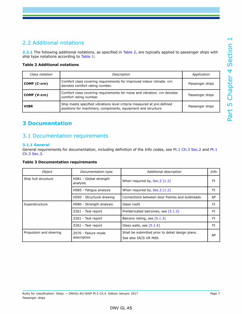
2.2 Additional notations
2.2.1 The following additional notations, as specified in Table 2, are typically applied to passenger ships withship type notations according to Table 1:
Table 2 Additional notations
Class notation Description Application
COMF (C-crn) Comfort class covering requirements for improved indoor climate. crndenotes comfort rating number. Passenger ships
COMF (V-crn) Comfort class covering requirements for noise and vibration. crn denotescomfort rating number. Passenger ships
VIBR Ship meets specified vibrations level criteria measured at pre-definedpositions for machinery, components, equipment and structure Passenger ships
3 Documentation
3.1 Documentation requirements3.1.1 GeneralGeneral requirements for documentation, including definition of the Info codes, see Pt.1 Ch.3 Sec.2 and Pt.1Ch.3 Sec.3.
Table 3 Documentation requirements
Object Documentation type Additional description Info
H081 - Global strengthanalysis When required by, Sec.2 [1.2] FI
H085 - Fatigue analysis When required by, Sec.2 [1.2] FI
Ship hull structure
H050 - Structural drawing Connections between door frames and bulkheads AP
H080 - Strength analysis Glass roofs FI
Z261 - Test report Prefabricated balconies, see [5.1.2] FI
Z261 - Test report Balcony railing, see [5.1.3] FI
Superstructure
Z261 - Test report Glass walls, see [5.1.4] FI
Propulsion and steering Z070 - Failure modedescription
Shall be submitted prior to detail design plans.
See also IACS UR M69.AP

Part
5 C
hapt
er 4
Sec
tion
1
Rules for classification: Ships — DNVGL-RU-SHIP Pt.5 Ch.4. Edition January 2017 Page 8Passenger ships
DNV GL AS
4 Product certificates
4.1 Certification requirements4.1.1 GeneralProducts shall be certified as required by Table 4.
Table 4 Certification requirements
Object Certificatetype
Issuedby
Certificationstandard Additional description
Cargo securing devices,fixed PC Society DNVGL-ST-0068
Cargo securing devices,portable PC If certified by the Society, DNVGL-ST-0068,
shall be applied.
For general certification requirements, see Pt.1 Ch.3 Sec.4.For a definition of the certification types, see Pt.1 Ch.3 Sec.5.
5 Testing
5.1 Survey and testing during newbuilding5.1.1 GeneralSurvey and testing requirements are given in Pt.2.
5.1.2 Prefabricated balcony modulePrefabricated balcony modules shall be structurally tested with a test load of 0.25 t/m2. No visual damage orpermanent deflections upon removal of the test load shall occur. A test report (TR), as defined in Pt.1 Ch.1Sec.4 [2.1.1], signed by the manufacturer, shall be submitted to the Society.
5.1.3 Balcony railingAn impact test according to EN 12600, or equivalent, shall be carried out to demonstrate that the glass panewill not fall out under accidental loading.
5.1.4 Glass superstructure side
1) For glass side walls which extend between decks, an impact test shall be carried out as per EN 12600pendulum test, to demonstrate that the glass pane will not fall out in case of an accidental load. A testreport (TR), as defined in Pt.1 Ch.1 Sec.4 [2.1.1], signed by the manufacturer, shall be submitted to thesociety. If the glass wall consists of several elements, the elements within one meter from the lowestdeck need to be tested.
2) For glass elements that are not supported along all four edges, a strength test shall be carried out. Theglass pane for testing shall be supported with an similar arrangement as the actual arrangement onboard the vessel. The test pressure shall be the actual design pressure Pd. The test pressure shall beachieved gradually within 30 seconds and reduced to zero within 30 seconds. A minimum of 3 load cyclesshall be done. After the load cycles, it shall be kept constant for 5 minutes (see Figure 1). The test willbe considered successful if no visible damage occurs to the glass or its supporting arrangements. A testreport (TR) shall be submitted to the society.

Part
5 C
hapt
er 4
Sec
tion
1
Rules for classification: Ships — DNVGL-RU-SHIP Pt.5 Ch.4. Edition January 2017 Page 9Passenger ships
DNV GL AS
Figure 1 Load cycles for testing of side wall glass pane

Part
5 C
hapt
er 4
Sec
tion
2
Rules for classification: Ships — DNVGL-RU-SHIP Pt.5 Ch.4. Edition January 2017 Page 10Passenger ships
DNV GL AS
SECTION 2 HULL
1 General
1.1 ArrangementPassenger ships often have multiple decks and long superstructures with many openings. The side and endbulkheads of the superstructure shall be effectively supported. Adequate transition arrangements shall befitted at the ends of effective continuous longitudinal strength members in the deck and bottom structures.
1.2 Calculation scope1.2.1 Global strengthFor passenger ships, the load carrying potential of the superstructure is typically accounted for in thelongitudinal strength assessment. In order to determine the effectiveness of the superstructure and thenormal and shear stress response of the hull girder, direct strength calculations using global finite elementanalysis may be required for ships with L > 150 m and where longitudinal shear members like ship side andlongitudinal bulkheads are not fully effective.The global direct strength model, when required, shall also be used for the strength assessment of the pillarsin order to account for both the loads arising from the global hull girder deflection and the local design deckloads.
1.2.2 Local FE analysis in way of openings and discontinuitiesTo obtain a stress distribution in structural elements with discontinuities or geometrical irregularities, e.g.recesses for doors and windows, knuckles, etc., and to evaluate local peak stress and fatigue stress range,local models with fine mesh are required. Local structural strength analysis as given in Pt.3 Ch.7 Sec.4applies to evaluate local peak stresses. The fatigue scope is defined in [4].The required fine mesh analysis and the selection of critical locations will depend on the arrangement of theship and the level of the global stresses.
1.2.3 Transverse strengthRequired scope for transverse strength analysis will be considered case by case based on number oftransverse bulkheads and other transverse strength members. When required, relevant dynamic load casesare described in [2.3.2].
1.2.4 Bow impactThe bow of ships with large flare angles and operating under medium to high service speeds plates, stiffenersand primary support members shall satisfy Pt.3 Ch.10 Sec.1. Additionally, for unconventional ship designswith extreme flare angle and where decks in the fore ship have large openings and steps, and with limitedcontinuous longitudinal structure, a direct bow impact analysis may be required, to verify the overall strengthof the bow structure.For bow impact direct analysis, see Pt.3 Ch.10 Sec.1 [3.3.4], for design loads and acceptance criteria.
1.2.5 DockingFor large passenger ships that may have large docking weight, special strength calculation of the bottomstructure in way of the docking blocks may be required. See Pt.3 Ch.3 Sec.5 [3.4] regarding requirements fordocking.Acceptance criteria for direct docking analysis based on beam- or FE analysis, to be taken according to:
— beam analysis: Pt.3 Ch.6 Sec.6 [2.2], AC-I— FE analysis: Pt.3 Ch.7 Sec.3 Table 1, AC-I.

Part
5 C
hapt
er 4
Sec
tion
2
Rules for classification: Ships — DNVGL-RU-SHIP Pt.5 Ch.4. Edition January 2017 Page 11Passenger ships
DNV GL AS
1.2.6 Wheel loadingDecks exposed to trolleys used in the handling of luggage shall satisfy the requirements given in Pt.3 Ch.10Sec.5. The trolleys shall be regarded as cargo handling vehicles in harbour condition.If one stiffener is subject to more than one load area, a direct strength analysis shall be used to determinethe required section modulus.
2 Hull girder loads for direct strength analysis
2.1 Longitudinal strength analysisFor passenger vessels the hull girder stresses in finite element analysis may normally be determined byconsideration of the most severe combinations of static and dynamic vertical hull girder bending momentsand shear forces, corresponding to design load scenario 2 in Pt.3 Ch.4 Sec.7 Table 1.For special design where the torsional response is considered critical, oblique sea conditions will be required.
2.2 Transverse strength analysis2.2.1 Static loads for transverse strength analysisDeck loads shall be applied as pressure loads to all decks above the bulkhead deck or life boat embarkationdeck such that the sum of the ships steel weight and deck loads equal the displacement at the consideredloading condition.
2.2.2 Dynamic loads for transverse strength analysisThe design wave load cases which shall be used to assess the transverse strength of the ship structure arethe beam sea load cases, BSR (1P/2P) and/ or BSR (1S/2S).For ship designs where the lower structure can be considered stiff i.e. the transverse displacement undertransverse loading is not significant, only the transverse envelope accelerations can be applied with thestructure fixed at bulkhead deck/life boat deck level.
2.3 Load applicationAcceptable methods for load application are described in DNVGL-CG-0138 Direct strength analysis of hullstructures in passenger ships.The applied loads on the FE model should be controlled against the still water and wave achieved bendingmoment and shear force curves to ensure agreement with the rule required bending moment and shear forcedistributions.
3 Pillars
3.1 Below deck connection under compressive loadsSmooth transmission of forces between pillars above and below deck shall be provided. The stress in thecontact area shall not exceed the yield stress of the material under the pillar loads.
3.2 Below deck connection under tension loadsFor pillars under tension loads, the average stress based on the contact area shall not exceed the valuesgiven in Pt.3 Ch.6 Sec.6 [3.2]. Full penetration welding shall be used for connections of local elements.

Part
5 C
hapt
er 4
Sec
tion
2
Rules for classification: Ships — DNVGL-RU-SHIP Pt.5 Ch.4. Edition January 2017 Page 12Passenger ships
DNV GL AS
4 Finite element analysis
4.1 Hull girder yield criteriaStresses in plating of all effective hull girder structural members shall not exceed the permissible values asgiven in Table 1.
Table 1 Permissible stresses for global finite element analysis
Permissible axialand principal stress
Permissible shear stress Permissible vonMises stress
175/k 110/k 220/k
4.2 Local strength analysis4.2.1 Control of peak stressesIn order to control the plastic deformation in corners of deck, bulkhead and wall openings, the peak stressesshall be calculated with the use of fine mesh local models. Peak stresses shall be calculated based on theloads described in [2].Reference is made to Pt.3 Ch.7 Sec.4 [4.2] for acceptable stress criteria for peak stresses.
4.2.2 Shear stress controlTo calculate shear stresses in areas with door and window openings or cut-outs, e.g. due to ventilation,piping cable ducts, in longitudinal bulkheads and side and vertical walls, local models with fine mesh shall bemade.Reference is made to Pt.3 Ch.7 Sec.4 [4.2] for acceptable stress criteria for peak stresses.
5 Fatigue strength
5.1 GeneralFor detailed description of the fatigue requirements to main class and fatigue assessment procedure,reference is made to Pt.3 Ch.9 and the Society's document DNVGL-CG-0129 Fatigue assessment of shipstructures, respectively. This sub-section describes the scope. A prescriptive fatigue assessment procedurefor passenger vessel is defined in the Society's document DNVGL-CG-0138 Direct strength analysis of hullstructures in passenger ships.
5.2 Structural details to be assessed using prescriptive analysisEnd connections of longitudinal stiffeners in the outer shell below the freeboard deck shall be assessedaccording to Pt.3 Ch.9, for ships with L > 150 m. Relative deflections and double hull bending can be ignored.
5.3 Structural details to be assessed using FE analysis with rule loadsFor vessels, for which direct hull girder strength calculation is required according to [1.2.1], the followingareas shall be assessed according to the Society's document DNVGL-CG-0129 Fatigue assessment of shipstructures, based on local FE models for free plate edges and hot spot models for welded details: for freeplate edges and hot spot models for welded details:
— corner details of door and window openings in longitudinal bulkheads and side walls
Part
5 C
hapt
er 4
Sec
tion
2
Rules for classification: Ships — DNVGL-RU-SHIP Pt.5 Ch.4. Edition January 2017 Page 13Passenger ships
DNV GL AS
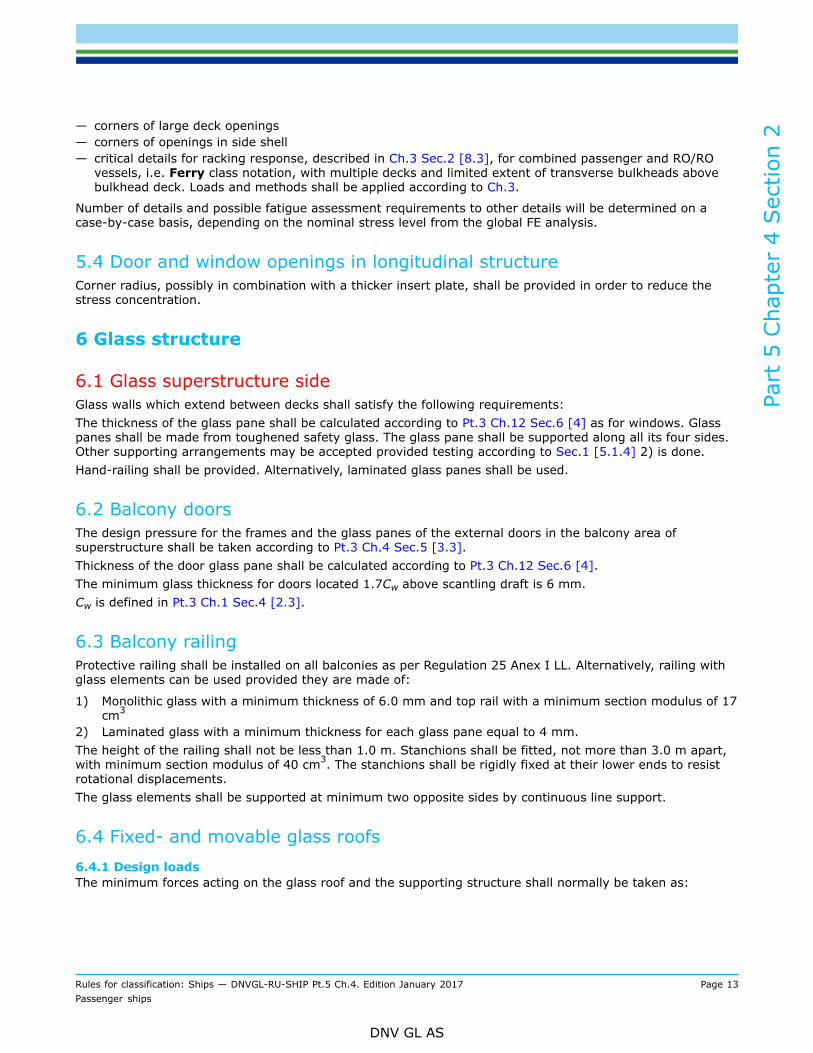
— corners of large deck openings— corners of openings in side shell— critical details for racking response, described in Ch.3 Sec.2 [8.3], for combined passenger and RO/RO
vessels, i.e. Ferry class notation, with multiple decks and limited extent of transverse bulkheads abovebulkhead deck. Loads and methods shall be applied according to Ch.3.
Number of details and possible fatigue assessment requirements to other details will be determined on acase-by-case basis, depending on the nominal stress level from the global FE analysis.
5.4 Door and window openings in longitudinal structureCorner radius, possibly in combination with a thicker insert plate, shall be provided in order to reduce thestress concentration.
6 Glass structure
6.1 Glass superstructure sideGlass walls which extend between decks shall satisfy the following requirements:The thickness of the glass pane shall be calculated according to Pt.3 Ch.12 Sec.6 [4] as for windows. Glasspanes shall be made from toughened safety glass. The glass pane shall be supported along all its four sides.Other supporting arrangements may be accepted provided testing according to Sec.1 [5.1.4] 2) is done.Hand-railing shall be provided. Alternatively, laminated glass panes shall be used.
6.2 Balcony doorsThe design pressure for the frames and the glass panes of the external doors in the balcony area ofsuperstructure shall be taken according to Pt.3 Ch.4 Sec.5 [3.3].Thickness of the door glass pane shall be calculated according to Pt.3 Ch.12 Sec.6 [4].The minimum glass thickness for doors located 1.7Cw above scantling draft is 6 mm.Cw is defined in Pt.3 Ch.1 Sec.4 [2.3].
6.3 Balcony railingProtective railing shall be installed on all balconies as per Regulation 25 Anex I LL. Alternatively, railing withglass elements can be used provided they are made of:
1) Monolithic glass with a minimum thickness of 6.0 mm and top rail with a minimum section modulus of 17cm3
2) Laminated glass with a minimum thickness for each glass pane equal to 4 mm.The height of the railing shall not be less than 1.0 m. Stanchions shall be fitted, not more than 3.0 m apart,with minimum section modulus of 40 cm3. The stanchions shall be rigidly fixed at their lower ends to resistrotational displacements.The glass elements shall be supported at minimum two opposite sides by continuous line support.
6.4 Fixed- and movable glass roofs6.4.1 Design loadsThe minimum forces acting on the glass roof and the supporting structure shall normally be taken as:

Part
5 C
hapt
er 4
Sec
tion
2
Rules for classification: Ships — DNVGL-RU-SHIP Pt.5 Ch.4. Edition January 2017 Page 14Passenger ships
DNV GL AS
Vertical force:
The pressure Pdl, in kN/m2, due to this distributed load for the static plus dynamic (S+D) design loadscenario shall be derived for each dynamic load case and shall be taken as:
where:
Pdl-s = static pressure, in kN/m2, due to the distributed load, shall be defined by the designer. Minimum0.15 t/m2 + self weight of glass roof
Pdl-d = dynamic pressure, in kN/m2, due to the distributed load, in kN/m2, shall be taken as:
fβ = as defined in Pt.3 Ch.4 Sec.4aZ = vertical envelope acceleration, in m/s2, at the centre of gravity of the distributed load, for the
considered load case, shall be obtained according to Pt.3 Ch.4 Sec.3 [3.3]PV = Pdl AH
AH = horizontal projected area of the glass roof in m2.
Transverse force on side walls in kN:
PT = PSI AT
PSI = side pressure taken from Pt.3 Ch.4 Sec.5 [3.3]AT = transverse projected area of the glass roof in m2.
Loads for horizontal stoppers in kN:
Combine PVC with PT
PVC = Pdlg0Av
Av = vertical projected area of the glass roof in m2.
6.4.2 Operational limitationsIf the roof is intended to be operated in at wind speeds exceeding 15 m/s, additional direct calculations maybe required.The restriction shall be stated in the operation manual for the vessel.
6.4.3 Stoppers and locking devicesThe stoppers and locking devices shall be provided such that in the event of failure of the hydraulic system,the roof will remain in open or closed position, respectively.

Part
5 C
hapt
er 4
Sec
tion
3
Rules for classification: Ships — DNVGL-RU-SHIP Pt.5 Ch.4. Edition January 2017 Page 15Passenger ships
DNV GL AS
SECTION 3 SYSTEMS AND EQUIPMENT
1 Emergency source of electrical power and emergency installations
1.1 Electrical systems1.1.1 GeneralPassenger vessels shall have an electrical installation complying with the requirements in Pt.4 Ch.8 with theclarifications and additions given in this sub-chapter.
1.1.2 Fire zonesElectrical distribution systems shall be so arranged that fire in any main vertical zone, as defined in Pt.4Ch.11, will not interfere with services essential for safety in any other such zone. This requirement willbe met if main and emergency feeders passing through any such zone are separated both vertically andhorizontally as widely as is practicable.
1.1.3 Emergency generatorWhere the emergency source of electrical power is a generator, it shall be started automatically.The emergency power supply system shall have capacity to supply the services listed in Pt.4 Ch.8 Sec.2 Table1 for a period of 36 hours. In a ship engaged regularly on voyages of short duration, the Administration ifsatisfied that an adequate standard of safety would be attained may accept a lesser period than the 36 hourperiod specified, but not less than 12 hours. Except when shorter periods are specified in these rules.
1.1.4 Additional emergency consumersIn addition, the following systems shall be supplied by the emergency power supply system:
1) For a period of 36 hours:
— in alleyways, stairways and exits giving access to the muster and embarkation stations, as requiredby regulation III/11.5
— the public address system or other effective means of communication which is provided throughoutthe accommodation, public and service spaces
— the means of communication which is provided between the navigating bridge and the main firecontrol station
— the fire door holding and release system— the automatic sprinkler pump, if any— the emergency bilge pump, and all the equipment essential for the operation of electrically powered
remote controlled bilge valves.
2) For a period of half an hour:
— the emergency arrangements to bring the lift cars to deck level for the escape of persons. Thepassenger lift cars may be brought to deck level sequentially in an emergency.
1.2 Lighting1.2.1 GeneralPassenger ships shall be provided with lighting systems as required by Pt.4 Ch.8. In addition, low-locationlighting and supplementary lighting shall be installed as follows:
1.2.2 Low-location lightingPassenger ships shall be provided with low-location lighting (LLL) complying with IMO Res. A.752(18).

Part
5 C
hapt
er 4
Sec
tion
3
Rules for classification: Ships — DNVGL-RU-SHIP Pt.5 Ch.4. Edition January 2017 Page 16Passenger ships
DNV GL AS
1.2.3 Supplementary lighting generalIn passenger ships, supplementary lighting shall be provided in all cabins to clearly indicate the exit so thatoccupants will be able to find their way to the door. Such lighting, which may be connected to an emergencysource of power or have a self-contained source of electrical power in each cabin, shall automaticallyilluminate when power to the normal cabin lighting is lost and remain on for a minimum of 30 min. (SOLASCh. II-1/41.6)
1.2.4 Supplementary lighting Passenger RORO vesselsFor RO-RO passenger ships (Reg. 11-1/42-1), in addition to the emergency lighting required by regulation42.2 (200), on every passenger ship with ro-ro cargo spaces or special category spaces as defined inregulation 11-213 (F101):
1) All passenger public spaces and alleyways shall be provided with supplementary electric lighting thatcan operate for at least three hours when all other sources of electric power have failed and under anycondition of heel. The illumination provided shall be such that the approach to the means of escapecan be readily seen. The source of power for the supplementary lighting shall consist of accumulatorbatteries located within the lighting units that are continuously charged, where practicable, from theemergency switchboard. Alternatively, any other means of lighting which is at least as effective may beaccepted by the Administration. The supplementary lighting shall be such that any failure of the lamp willbe immediately apparent. Any accumulator battery provided shall be replaced at intervals having regardto the specified service life in the ambient conditions that they are subject to in service; and
2) A portable rechargeable battery operated lamp shall be provided in every crew space alleyway,recreational space and every working space which is normally occupied unless supplementary emergencylighting, as required by sub paragraph.1, is provided.
1.3 Services to be supplied1.3.1 GeneralThe electrical power available shall be sufficient to supply all those services that are essential for safetyin an emergency, due regard being paid to such services as may have to be operated simultaneously. Theemergency source of electrical power shall be capable, having regard to starting currents and the transitorynature of certain loads, of supplying simultaneously at least the following services for the periods specifiedhereinafter, if they depend upon an electrical source for their operation, as stated in the following items[1.3.2] to [1.3.7].In a ship engaged regularly on voyages of short duration, the administration if satisfied that an adequatestandard of safety would be attained may accept a lesser period than the 36 hour period specified in items[1.3.2] to [1.3.5] but not less than 12 hours.
1.3.2 Emergency lightingFor a period of 36 hours, emergency lighting:
1) at every muster and embarkation station and over the sides as required by regulations III/11.4 andIII/16.7
2) in alleyways, stairways and exits giving access to the muster and embarkation stations, as required byregulation III/11.5
3) in all service and accommodation alleyways, stairways and exits, personnel lift cars4) in the machinery spaces and main generating stations including their control positions5) in all control stations, machinery control rooms, and at each main and emergency switchboard6) at all stowage positions for firemen's outfits7) at the steering gear; and8) at the fire pump, the sprinkler pump and the emergency bilge pump referred to in [1.3.4] and at the
starting position of their motors.

Part
5 C
hapt
er 4
Sec
tion
3
Rules for classification: Ships — DNVGL-RU-SHIP Pt.5 Ch.4. Edition January 2017 Page 17Passenger ships
DNV GL AS
1.3.3 Navigation and communicationFor a period of 36 hours:
1) The navigation lights and other lights required by the International Regulations for Preventing Collisionsat Sea in force.
2) The VHF radio installation required by regulation IV/7.1.1 and IV/7.1.2; and, if applicable:
— 2.1 the MF radio installation required by regulations IV/12.1.1, IV/12.1.2, IV/10.1.2 and IV/10.1.3— 2.2 the ship earth station required by regulation IV/10.1.1.; and— 2.3 the MF/HF radio installation required by regulations IV/10.2.1, IV/10.2.2 and IV/11.1.
3) All internal communication equipment required in an emergency shall include:
— the means of communication which is provided between the navigating bridge and the steering gearcompartment
— the means of communication which is provided between the navigating bridge and the position in themachinery space or control room from which the engines are normally controlled
— the means of communication which is provided between the bridge and the radio telegraph or radiotelephone stations
— the means of communication which is provided between the officer of the watch and the personresponsible for closing any watertight door which is not capable of being closed from a central controlstation
— the public address system or other effective means of communication which is provided throughoutthe accommodation, public and service spaces
— the means of communication which is provided between the navigating bridge and the main firecontrol station.
4) The shipborne navigational equipment as required by regulation V/12.
5) The fire detection and fire alarm system, and the fire door holding and release system.
6) For intermittent operation of the daylight signalling lamp, the ship's whistle, the manually operated callpoints and all internal signals that are required in an emergency;
unless such services have an independent supply for the period of 36 hours from an accumulator batterysuitably located for use in an emergency.
1.3.4 Fire pumps and bilge systemsFor a period of 36 hours:
1) one of the fire pumps required by SOLAS II-2/10.2.2.2 and 10.2.2.32) the automatic sprinkler pump, if any; and3) the emergency bilge pump, and all the equipment essential for the operation of electrically powered
remote controlled bilge valves.
1.3.5 Steering gearFor the period of time required by regulation 29.14 (Pt.4 Ch.10 Sec.1 [5.3]) the steering gear if required tobe so supplied by that subsection.
1.3.6 Watertight doorsFor a period of half an hour:
— Any watertight doors required by SOLAS Reg. II-1/15 to be power operated together with their indicatorsand warning signals.

Part
5 C
hapt
er 4
Sec
tion
3
Rules for classification: Ships — DNVGL-RU-SHIP Pt.5 Ch.4. Edition January 2017 Page 18Passenger ships
DNV GL AS
1.3.7 Lift carsFor a period of half an hour:
— The emergency arrangements to bring the lift cars to deck level for the escape of persons. The passengerlift cars may be brought to deck level sequentially in an emergency.
1.3.8 Generator as emergency source of electrical powerWhere the emergency source of electrical power is a generator, it shall be:
1) Started automatically upon failure of the electrical supply from the main source of electrical power andshall be automatically connected to the emergency switchboard; those services referred to in 400 shallthen be transferred automatically to the emergency generating set. The automatic starting system andthe characteristic of the prime-mover shall be such as to permit the emergency generator to carry its fullrated load as quickly as is safe and practicable, subject to a maximum of 45 seconds; unless a secondindependent means of starting the emergency generating set is provided, the single source of storedenergy shall be protected to preclude its complete depletion by the automatic starting system; and
2) Provided with a transitional source of emergency electrical power according to [1.3.9].
1.3.9 Transitional source of emergency powerThe transitional source of emergency electrical power required by item [1.3.8] 2) shall consist of anaccumulator battery suitably located for use in an emergency which shall operate without recharging whilemaintaining the voltage of the battery throughout the discharge period within 12% above or below itsnominal voltage and be of sufficient capacity and so arranged as to supply automatically in the event offailure of either the main or emergency source of electrical power at least the following services, if theydepend upon an electrical source for their operation:For half an hour:
1) The lighting required by items [1.3.2] and [1.3.3] 1);2) All services required by items [1.3.3] 3), [1.3.3] 5) and [1.3.3] 6), unless such services have an
independent supply for the period specified from an accumulator battery suitably located for use in anemergency.
Power to operate the watertight doors, as required by SOLAS Reg. II-1/15, but not necessarily all ofthem simultaneously, unless an independent temporary source of stored energy is provided. Power to thecontrol, indication and alarm circuits as required by SOLAS Reg. II-1/15, for half an hour.

Part
5 C
hapt
er 4
Sec
tion
4
Rules for classification: Ships — DNVGL-RU-SHIP Pt.5 Ch.4. Edition January 2017 Page 19Passenger ships
DNV GL AS
SECTION 4 STABILITY
1 Stability
1.1 ApplicationShips with class notation Passenger ship and Ferry shall comply with the requirements according to [1.2].
1.2 Intact stability1.2.1 Intact stability criteriaPassenger ships shall comply with Pt.3 Ch.15 with the supplementing requirements as given in IMO 2008Intact Stability Code (IMO Res. MSC.267(85)) Part A Ch. 3.1.1 and 3.1.2.
1.2.2 Loading conditionsCompliance with the stability requirements shall be documented for the standard loading conditions given inIMO 2008 Intact Stability Code (IMO Res. MSC.267(85)) Part B Ch. 3.4.1.1.

Part
5 C
hapt
er 4
Cha
nges
– h
isto
ric
Rules for classification: Ships — DNVGL-RU-SHIP Pt.5 Ch.4. Edition January 2017 Page 20Passenger ships
DNV GL AS
CHANGES – HISTORIC
January 2016 edition
Main changes January 2016, entering into force as from date ofpublication
• Sec.2 Hull— [1.2.3] and [2.2]: Scope and load combinations for global FE transverse strength analysis is clarified— [6.3]: More detailed requirements to balcony railings included
October 2015 edition
GeneralThis is a new document.The rules enter into force 1 January 2016.

DNV GLDriven by our purpose of safeguarding life, property and the environment, DNV GL enablesorganizations to advance the safety and sustainability of their business. We provide classification andtechnical assurance along with software and independent expert advisory services to the maritime,oil and gas, and energy industries. We also provide certification services to customers across a widerange of industries. Operating in more than 100 countries, our 16 000 professionals are dedicated tohelping our customers make the world safer, smarter and greener.
SAFER, SMARTER, GREENER