running floor ii dx sae owners manual original...
TRANSCRIPT

1
KEITH® RUNNING FLOOR II® DX
SAE OWNERS MANUALOriginal Instructions
High Quality Ball Seal Interchangeable CylindersAdvanced Switching Valve External Check ValvesCenter Frame Design No Hydraulic HosesCross-Drive Support Strong Drive FrameWinged Bearings Compact DesignSnapdown Bearings & Flooring
12/18/14
KEITH Mfg. Co.World Headquarters800-547-6161541-475-3802541-475-2169 fax

We at KEITH Mfg. Co. are very happy that you have decided to equip your trailer with the KEITH® RUNNING FLOOR II® DX unloading system. We take great pride in the fact that we manufacture the simplest and lowest maintenance self-unloading system available. Installing the KEITH® RUNNING FLOOR II® DX unloader in your trailer provides you with the versatility to load or unload virtually any type of material.
The following pages contain information on the operation of your KEITH® RUNNING FLOOR II® DX unloader.
In addition, we have provided information on the type of hydraulic wet kit that will be needed on your tractor. Please be sure to use the recommended pumps, filters and pressure relief valves listed, or approved equivalent equipment. It is critical to adhere to the outlined hydraulic wet kit specifications. Failure to follow the guidelines concerning required operation pressures can lead to your system operating improperly.
Please review the entire manual before operating the KEITH® RUNNING FLOOR II® DX unloading system. If you have any questions or concerns, do not hesitate to contact our factory toll-free at 800-547-6161 or via email at [email protected] and our trained personnel will be happy to assist you.
Thank you again for equipping your trailer with a KEITH® RUNNING FLOOR II® DX unloader.
Sincerely,
Keith Foster Mark Foster Founder President
KEITH®, WALKING FLOOR® & RUNNING FLOOR II® DX are registered worldwide trademarks of KEITH Mfg. Co.

1
TABLE OF CONTENTS RUNNING FLOOR II® DX
WARRANTY AND SAFETY
Warranty............................................................................................................... Safety................................................................................................................... Safety Decals.......................................................................................................
OPERATION
Safe Start-Up/Shut Down..................................................................................... Driver Check List.................................................................................................. Operation of Your Running Floor II® DX Unloader................................................ Component Location Guide.................................................................................. How It Works........................................................................................................ Plumbing Diagram................................................................................................ Start-Up Check List.............................................................................................. Wet Kit Diagram................................................................................................... Floor Speed.......................................................................................................... Wet Kit Information............................................................................................... TROUBLESHOOTING Switching Valve Adjustment.................................................................................. Switching Valve Troubleshooting.......................................................................... Check Valve Troubleshooting............................................................................... Replacing a Check Valve...................................................................................... Control Valve, Ball Valve Troubleshooting............................................................ Hydraulic Cylinders Troubleshooting.................................................................... Repairing Cylinders.............................................................................................. KEITH® RUNNING FLOOR II® DX Oil Flow Diagram........................................... Suggested Preventive Maintenance Schedule.....................................................
PARTS
Drive Frame & Related Components................................................................... Cross-Drive Assembly.......................................................................................... Cylinder Assembly................................................................................................ Hydraulic Tubes & Fittings.................................................................................... Check Valve Assembly.......................................................................................... Control Valve Assembly........................................................................................ Switching Valve Assembly.................................................................................... Ball Valve Assembly.............................................................................................. Electric On/Off Ball Valve...................................................................................... Restrictor Valve..................................................................................................... Electric Control Valve............................................................................................ On/Off & Control Valve Handle Assemblies.......................................................... Front Shield Assembly.......................................................................................... Floor Components................................................................................................
MAINTENANCE AND WARRANTY
Maintenance for New Systems............................................................................. Warranty Registration...........................................................................................
6789-1011-121313141415
16-171819202122232425
26-2728-2930-3132-3940-4243-4445-464748-495051-5253-555657-58
5960
2-345

2
Revision Date July 14, 2008
RUNNING FLOOR II DX
LIMITED WARRANTY (USA/CANADA)
KEITH Mfg. Co. hereby warrants, only to the first owner of a new KEITH® RUNNING FLOOR II® DX unloader from the factory or selling distributor that the product shall be free from defects in material and workmanship for a period of one year after delivery to the first registered owner. Hydraulic parts and components shall be warranted as free from defects in material and workmanship for a period of two years to the first registered owner. This warranty does not cover normal wear and tear and maintenance and is not to be construed as a service contract. Owners Obligation: To qualify for warranty coverage, a “warranty card must be completed and returned to Keith Mfg” and the equipment must be subject to normal use and service only. Definition of Normal Use and Service: Normal use and service means the loading and/or unloading of uniformly distributed, non-corrosive material, properly restrained and secured, on properly maintained public roads, with gross vehicle weights not in excess of factory rated capacity. For stationary installations, normal use and service means the conveying of uniformly distributed, non-corrosive materials, with weights not in excess of factory rated capacity. Sole and Exclusive Remedy: If the product covered hereby fails to conform to the above stated warranty, KEITH Mfg. Co.’s sole liability under this warranty and the owner’s sole and exclusive remedy is limited to repair or replacement of the defective part(s) at a facility authorized by KEITH Mfg. Co. This is the owner’s sole and exclusive remedy for all contract claims, and all tort claims including those based on the strict liability in tort and negligence. Any defective part(s) must be shipped freight prepaid to KEITH Mfg. Co, Madras, Oregon. Except As Expressly Set Forth Above, KEITH Mfg. Co. Makes No Warranties: Express, implied or statutory, specifically: No warranties of fitness for a particular purpose or warranties of merchantability are made. Further, KEITH Mfg. Co. will not be liable for incidental damages or consequential damages such as, but not limited to, loss of use of the product, damage to the product, towing expenses, attorney’s fees and the liability you may have in respect to any other reason. Tort Disclaimer: KEITH Mfg. Co. shall not have any liability in tort with respect to the products, including any liability based on strict liability in tort and negligence. If This Warranty Violates Law: To the extent any provision of this warranty, contravenes the law of any jurisdiction, that provision shall be inapplicable in such jurisdiction and the remainder of the warranty shall not be affected thereby.

3
A summary of the warranty conditions are as follows:
• The warranty period is for the first equipment owner only
• A warranty period of (1) one year for the entire Running Floor II DX unloader from date of sale by trailer manufacturer.
• A warranty period of (2) two years for the hydraulic parts and components from date of sale by trailer manufacturer.
• The Running Floor II DX unloader must be installed by the trailer builder according to KEITH® installation procedures.
• KEITH recommended maintenance and control procedures must be followed.
• In the case of a malfunction, trailer manufacturer, or KEITH must be informed.
The following components are not covered by the warranty:
• Malfunction of equipment, or caused by equipment, which was not supplied by KEITH Mfg. Co.
• Malfunction caused by the use of dirty oil, or oil of the wrong type.
• Malfunction caused by overheated oil: maximum temperature 60 °C or 140°F.
• Malfunction caused by corrosive materials.
• Malfunction caused by overloading or improper use.
• Malfunction caused by repair work performed by an unauthorized third party.
• Filter elements and components, which are subject to wear-and-tear.
• Defects in electrical components due to incorrect connection and/or incorrect voltage levels.
The warranty is void if:
• The Running Floor II DX unloader is used for purposes which have not been recommended by KEITH Mfg. Co.
• The wet kit does not meet KEITH system recommendations.
• The Running Floor II DX unloader is not installed properly.
• Loads in excess of legal limits are moved with the system without written permission from KEITH Mfg. Co.

4
SAFETY RUNNING FLOOR II® DX
To Prevent Possible Injury or Death
1. Do Not Operate the floor with the doors closed.2. Do Not Stand behind the trailer or in the discharge area when the floor is operating.3. Do Not Make adjustments to the unloading mechanism with the floor operating.4. Do Not Operate unloader when protective covers and screens are not in place.5. Do Not Go underneath the trailer when floor is operating.6. Do Not Leave the trailer unattended while the unloader is in operation.
Always:1. Disengage the trailer from the (P.T.O.) hydraulic power unit before service and maintenance.2. Shut off the power supply before going underneath the trailer.3. Stay away from any oil leaks when hydraulic pressure is high.4. Shut off the hydraulic power take off unit (P.T.O.) before moving the trailer.5. Make certain no one is in the trailer during loading.
!!Keep your hands, body parts and loose clothing away from the floor slats and drive mechanism when the unloading system is in operation!!
Each decal notifies the operator of instructions or potential safety hazards associated with the KEITH® WALKING FLOOR® DX unloader. If your dealer has not placed the decals during installation, please follow the decal placement guide provided and place the decals as directed. If you have not been provided with the operational and safety decals, please contact your dealer, or KEITH Mfg. Co. directly and we will provide a set of decals for your application and use. If you have any questions or concerns regarding the decal placement, please don’t hesitate to contact your dealer or KEITH Mfg. Co.

5
SAFETY DECALS RUNNING FLOOR II® DX
1 2 3
4 7
8 9 10
5 6
*3. Decal should be applied so it is completely visible with the doors open.
RFII DECAL KIT: #84804002 QTY: ITEM #SIZE:
14222211111
9 102
2
6
45
*3
1
8
*3
2
6
45
2
7
6” x 2”6” x 2”6” x 2”6” x 2”6” x 2”4” x 2”4” x 2”6” x 2”6” x 2” 6” x 2”N.A.
1. Danger/Stored Energy (English)2. Pinch Point (English) 3. Danger/Burial (English) 4. Read Manual (English) 5. Hydraulic Pressure (English) 6. Warning Hot Surface (English) 7. Guard (English) 8. Danger/Burial Do Not Enter (English) 9. Ball Valve 10. Control Valve (LH)N.A. Placement Instuction Guide
8480410 1 84804124 84804100 84804123 84804128 84804127 8480412684804132 848041298480413184804001

6
OPERATION RUNNING FLOOR II® DX
Safe Start-Up/Shutdown
1. Set parking brake on truck and trailer.2. Open trailer doors fully and secure doors with provided chains or loop rings.
ALWAYS have doors fully open! Do not, under any circumstances, engage the Power Take Off / Pump (P.T.O.) or WALKING FLOOR® unloader with the doors of the trailer closed. Do not go under trailer body or enter the trailer while the system is in operation, nor allow anyone to stand or move through the area where the load is being discharged.
3. Connect hydraulic hoses to power unit (truck).4. Engage P.T.O. and set to unload RPM.5. Close the ball valve by pulling the handle outward. 6. While unloading, NEVER leave truck and trailer unattended!7. After unloading has been completed, stop the floor with all slats in the forward
position by placing the ball valve in the open position.8. Disengage P.T.O.9. Close doors, disconnect and secure hydraulic hoses.10. If a problem should arise while unloading, promptly do one of the following:
a. Disengage P.T.O. system. b. Open ball valve.
CAUTIONObservations may be made while system is operating for troubleshooting purposes, but NEVER touch any moving part or attempt to make any adjustments to the system with the Power Take Off/Pumping system engaged or the WALKING FLOOR® unloader operating. Do not attempt to make adjustments or repairs without consulting with a trained service technician from your company or contact KEITH Mfg. Co. at 1-800-547-6161 or via email at [email protected] for further assistance.

7
OPERATION RUNNING FLOOR II® DX
Driver Check List
Pre-trip Check: Trailer Empty1. Inspect hoses and connectors for damage and contamination. Clean all dirt and
water from connectors before hooking up.2. Inspect drive unit for leaking fittings or hoses and visible damage.3. Open trailer door and inspect flooring for impact damage.4. Inspect flooring at the rear of the trailer for loose or bent slats that may have
popped up.5. Hook up hydraulic connectors and operate the floor. Inspect for leaks while
operating. Engage and disengage ball valve to check for proper operation. Check control valve for proper operation (Forward, reverse).
6. If problems are found, report them to the maintenance shop as soon as possible.7. Secure trailer door and proceed.
Note: If trailer is loaded, perform steps 3 and 4 after unloading.
As the driver, you will see damage or operational problems before anyone else. Please report it as soon as possible.

8
OPERATION RUNNING FLOOR II® DX
Operation of your KEITH® Running Floor II® DX Unloader
UNLOADING 1. Before beginning to unload, make sure the trailer door(s) is/are open. 2. To unload with your KEITH® Running Floor II® DX system, pull the control valve handle all the way out. (See Diagram A.) 3. Make sure that the ball valve, located between the pressure and return lines, is in the closed (run) position. (See Diagram B.) This ball valve is used for the emergency shut-off. 4. Engage the P.T.O., then bring the tractor engine up to the predetermined unloading RPM. Your trailer floor should now be operating. 5. To stop the floor at any time during the loading or unloading process, switch the ball valve to the open (Stop) position. (See Diagram B.)
LOADING 1. To load with your bi-directional KEITH® Running Floor II® DX system, simply push the control valve handle all the way in. (See Diagram A.) Then follow instructions 3, 4 and 5 listed above.
!!Note!! Make sure the trailer door(s) is/are open BEFORE starting the floor or the trailer door(s) may be damaged. The nose of the trailer may also be damaged by the load force when loading.
RUN
Diagr am B:Ball Va lve
STOP RUN
Diagram A:Control Valve
PULL TO UNLOADHandle Pulled Completely Out
PUSH TO LOADHandle Pushed Completely In

9
OPERATION GUIDE RUNNING FLOOR II® DX
#1
#2
#3
1
2
3
p8 66924
Left SideRight Side
Front of Trailer
Component Location GuideLeft Hand Controls
View from underneath trailer
Serial Numbers are located underneathfront stiffener plate.
Cylinders
Check Valves
Cross-Drives
Drive Frame Hydraulic Tubes & Fittingsfor Left Hand Controls(see page 32-35)
Some unbalanced drivesmay have a restrictor valvein place of this fitting.
Switching Valve
ReturnPressure
On/Off Ball Valve
On/Off Ball Valve HandleLeft hand controlsPull out to run
ControlValve
Load/Unload ControlValve HandleLeft hand controlpull out to unload

10
OPERATION GUIDE RUNNING FLOOR II® DX
Component Location GuideRight Hand Controls
Hydraulic Tubes & Fittingsfor Right Hand Controls(see pages 36-39)
Some unbalanced drivesmay have a restrictor valvein place of this fitting.
Left SideRight Side
View from underneath trailer
Switching Valve
Drive Frame
Serial Numbers are located underneathfront stiffener plate.
ReturnPressure
On/Off Ball Valve
Control Valve
Cross-Drives
On/Off Ball Valve HandleRight hand controls
Pull out to run
Load/Unload ControlValve Handle
Right hand controlpull out to unload
#1
#2
#3
1
2
3
Cylinders
p9 66924
Check Valves

11
OPERATION RUNNING FLOOR II® DX
How It Works
Initial StateAll slats/planks at discharge end.
Stage 1 The first group of slats/planks moves under the load. Load does not move.
Stage 2 The second group of slats/planks moves under the load. Load does not move.
Stage 3 The final group of slats/planks moves under the load.Load does not move.
Stage 4 All slats/planks move together. Load moves toward the discharge end.
(Stages 1, 2 & 3 require more pressure than stage 4.)

12
OPERATION RUNNING FLOOR II® DX
Running Floor II® DX DriveHow The System Works
Unload Cycle Description-
Phase One:Cylinder (#1), the left side cylinder, travels toward the front of the trailer. As it reaches the end, the #1 check valve is opened. This releases blocked oil, allowing cylinder (#2), the center cylinder, to travel.
Phase Two:Cylinder (#2) travels toward the front of the trailer. The #2 check valve is opened, releasing oil and allowing cylinder (#3), the right side cylinder, to travel.
Phase Three:Cylinder (#3) travels toward the front of the trailer. As it reaches the end of its travel, a loop on the #3 cross-drive pushes the threaded rod connected to the switching valve. The threaded rod is pushed into the switching valve, changing the hydraulic oil flow direction.
Phase Four:As all three cylinders travel toward the rear of the trailer, the load is transferred to the discharge end. When all cylinders have reached their maximum stroke, the loop on the #1 cross-drive pushes the threaded rod connected to the switching valve. The threaded rod is pushed into the switching valve, changing the flow of oil and starting the cycle over.

13
OPERATION RUNNING FLOOR II® DX
*NOTE: The pressure and return lines must attach to their proper ports on the switching valve. If you have any questions or problems, call KEITH Mfg. Co. at 800-547-6161.
Start-Up Check List for the KEITH® RUNNING FLOOR II® DX System
Before starting your new KEITH® RUNNING FLOOR II® DX unloader, a quick start-up check should be made.
1. Is your entire system plumbed to the plumbing diagram?2. *Pump: Will it pump 30-35 GPM at 3000 PSI?3. *Relief Valve: Is it set at 2800-3000 PSI?4. Oil: Have you filled the reservoir?5. Power Take Off: Is the P.T.O. engaged?6. Quick Disconnects: Are they the same size and type? Are they completely engaged?7. Ball Valve: Is the ball valve on the drive unit closed?8. Is the pressure line on the trailer attached to the pressure line on the tractor and the return line on the trailer attached to the return line on the tractor?
*If the information about your pump and relief valve is not known, a pressure/flow check will help determine this information. Be sure that your entire wet kit system meets the requirements of the hydraulic wet kit specifications in this manual.
Plumbing Diagram

14
OPERATION RUNNING FLOOR II® DX
3/4" GRD 8 Hex Bolt
Wet Kit Diagram
Floor Speed in Relation to Engine RPM
Example: With a P.T.O. output shaft speed rated at 118% of engine RPM, using a P51, P051, P5100 or PL27 type pump with dowelled housing and a 2 1/2” gear. The engine RPM in relation to the floor movement is as follows.
Above specifications are for RUNNING FLOOR II® DX drive unit with 3.0” bore cylinders. These are approximate feet per minute only and should be used strictly as a guide.
Note: KEITH Mfg. Co. recommends installing KEITH® RUNNING FLOOR II® DX drive unitsincorporating 3.5 inch cylinders for use in all semi-trailers with three or more axles.
Engine RPM Pump Output Speed Ft/ Minute* Unloading Time 45 ft Trailer950 RPM 30 g/minute 8.2 ft/minute 7-8 minutes1430 RPM 45 g/minute 12.5 ft/minute 5-6 minutes1900 RPM 60 g/minute 16.4 ft/minute 3-4 minutes

15
OPERATION RUNNING FLOOR II® DX
Wet Kit Information
*Note: It is critical that the relief valve is set at no less than 2800 PSI and no more than 3000 PSI.
Transmission: This wet kit is designed to be used with most transmissions. Power Take Off (P.T.O.) specifications may vary with some transmissions. Please check with your supplier for specific applications.
Oil: Chevron AW46 hydraulic oil or equivalent. (Lower viscosity in colder climates).
P.T.O.: Chelsea series 442/489 or Muncie CS6/CS8 Power Take Off unit, rated at approximately 118-125% of engine RPM.(Electronic Overspeed Control is highly recommended).
Pump: P51, P051, P5100 or PL27 type pump with dowelled housing and a 2 1/2” gear. (Recommend a 2” four bolt, suction port).
Filter: Filter should be 10 to 25 micron on the return line.Filter should be a double element Zinga or equivalent.Filter head #DF-15-25. MF 2215-25-0-2-0.Filter element #LE-10 or LE-25.(The filter element should be changed after 6 hours initially, and then every 6 months thereafter. This may vary with the operating environment).
Hydraulic Reservoir:
Should hold approximately 1 gallon of oil for every gallon per minute you plan to pump, i.e. 40 GPM = 40 gallon reservoir. Reservoir should hold a minimum of 40 gallons of oil.
Suction Line: Suction line from the tank to the pump should be no more than 5’ in length and a minimum of 2” inside diameter. Example: SAE-100R4. (This type of line has a spiral wire to keep the hose from collapsing under suction).
Pressure Line: Hose from truck to trailer should be 1” 16 SAE-100R2. Return Line: Hose from trailer to filter should be 1” 16 SAE-100R1.
Hose from filter to tank should be 1¼” 20 SAE-100R1.*Pressure Relief Valve:
High quality valve, with the ability to relieve full pump flow at 3000 PSI.

16
TROUBLESHOOTING RUNNING FLOOR II® DX
Switching Valve Adjustment
NOTE: This view is from the right side of the trailer. All cylinders are shown to the rear of the trailer.

17
TROUBLESHOOTING RUNNING FLOOR II® DX
Switching Valve Adjustment
Tools needed: (2) 9/16 inch open-end wrenches.Most switching valves are incorrectly replaced because they are out of adjustment. Always adjust the switching valve as described below.
1. Use the ball valve to stop the drive unit.The ball valve is located toward the front of the drive unit, in front of the hydraulic cylinders. Move the ball valve handle toward the center of the trailer, which will al-low the hydraulic oil to by-pass the drive unit.
2. Loosen the 3/8” jam nuts located on the threaded rods on each end of the switching valve.On each threaded rod there are two flat washers and a grommet. The 3/8” jam nuts are located between the switching valve and the washers. After loosening the nuts, adjust them toward the switching valve. Doing this will throw the switch-ing valve out of adjustment. Repeat the process at the other end of the switching valve.
3. Start the truck engine and engage the P.T.O.Let the clutch out slowly. Pull the ball valve handle toward the driver’s side. The drive unit will move to the load or unload direction. The system will lock up and be under high pressure when the cylinders reach the end of the stroke. Immedi-ately push the ball valve handle toward the center of the trailer. This will allow the hydraulic oil to bypass the system. At this point, the cylinders will be at maximum stroke.
4. Disengage P.T.O.5. Push the threaded rod in the direction that the cylinders are bottomed.
Slide the washers and rubber grommet out toward the loop on the cross drive. Turn the 3/8” jam nuts out until they are tight against the washers. Then turn the first nut one extra turn. Bring the second nut up to the first nut and tighten the two together, setting the jam nuts.
6. Engage P.T.O.7. Move the ball valve handle slowly, causing the hydraulic cylinders to travel
to the opposite direction. Let the cylinders travel until they lock up. Then push the ball valve handle to the center.
8. Disengage P.T.O.9. Push the threaded rod in the direction that the cylinders are bottomed. Slide
the washers and rubber grommet out toward the loop on the other cross drive. Turn the 3/8” jam nuts out until they are tight against the washers. Then turn the first nut one extra turn. Bring the second nut up to the first nut and tighten the two together, setting the jam nuts.
10. The switching valve adjustment is completed.

18
TROUBLESHOOTING RUNNING FLOOR II® DX
Problem: Cylinder (#1) moves toward the front of the trailer. Cylinder (#2) moves toward the front of the trailer. Cylinder (#3) moves toward the front of the trailer; then the system stops.
Cause: The threaded rod nuts on the discharge end of the switching valve are not adjusted correctly.
Solution: Break the two nuts apart and adjust toward the rear of the trailer.
Problem: All three cylinders move toward the rear of the trailer; then the system stops.
Cause: The threaded rod nuts on the forward end of the switching valve are not adjusted correctly, or there is not enough hydraulic pressure. (See *Note.)
Solution: Break the two nuts apart and adjust toward the front of the trailer.
Problem: Floor runs fine empty or with a light load, but will not cycle with a heavy load.
Cause: The nuts on the threaded rod are slightly out of adjustment, or there is not enough hydraulic pressure. (See *Note.)
Solution: Break the two nuts apart and adjust them away from the Switching Valve body.
Problem: After installing a new switching valve, the floor will not move.Solution: The switching valve is out of adjustment or the new-style switching valve
will not work if the pressure and return lines are backward.
Problem: The cylinders cycle to the front correctly— cylinder (#1), followed by (#2) then (#3). Then, as all three cylinders begin to move toward the rear, (#3) cross-drive and cylinder move two to three inches back and forth.
Solution: The switching valve loop on the cross-drive is bent and binding against the threaded rod. Bend the loop away from the threaded rod so that it will enable the threaded rod to travel freely.
*Note: (If floor stops in the full rear position and the switching valve has switched, you may not have enough oil pressure. Less pressure is required to move the load than to pull the slats 1/3 at a time under the load.)
Switching Valve Troubleshooting

19
TROUBLESHOOTING RUNNING FLOOR II® DX
Check Valve Troubleshooting
The exterior check valve is designed to vent oil from the return side of the cylinder. It does not direct pressurized oil into the cylinder.
UnloadingProblem: Cylinders (#1) and (#2) extend together toward the front of trailer.Cause: The check valve at the forward end of cylinder (#1) has malfunctioned.Solution: Rebuild or replace the check valve.
Problem: Cylinders (#2) and (#3) extend together toward the front of trailer.Cause: The check valve at the forward end of cylinder (#2) has malfunctioned.Solution: Rebuild or replace the check valve.
Problem: All three cylinders extend together toward the front of trailer.Cause: The check valves at the forward end of cylinders (#1) and (#2) have
malfunctioned (Unlikely) or oil is leaking in the control valve and “floating” the check valves.
Solution: Rebuild or replace the check valves or control valve.
LoadingProblem: Cylinders (#2) and (#3) extend together toward the rear of trailer.Cause: The check valve at the rear end of cylinder (#3) has malfunctioned.Solution: Rebuild or replace the check valve.
Problem: Cylinders (#1) and (#2) extend together toward the rear of trailer.Cause: The check valve at the rear end of cylinder (#2) has malfunctioned.Solution: Rebuild or replace the check valve.
Problem: All three cylinders extend together toward the rear of trailer.Cause: The check valves at the rear end of cylinders (#2) and (#3) have malfunctioned
(Unlikely) or oil is leaking in the control valve and “floating” the check valves.Solution: Rebuild or replace the check valves or control valve.
See “Replacing a Check Valve” Page 20The check valves at the rear of the cylinders (discharge end) do nothing when you are unloading. The check valves at the rear are used for loading only.
Note: When empty, some trailers will cycle in sequence forward 1-2-3, then back 3-2-1, (Instead of all slats moving back together). This is not a malfunction; no repairs are needed. When a load is put on a trailer, the drag will cause the floor to sequence properly.

20
TROUBLESHOOTING RUNNING FLOOR II® DX
Replacing a Check Valve
78
83
84
8592
86
8988
87
90
93
Cylinder Rod
91
97Hydraulic Tubes
96
95
Assembled Check ValveTubes and Clamps
Assembled Check ValveWith Straight Connectors
Assembled Check ValveWith Long Straight Connector
98
Check Valve Assembly
p19-39 66914
97
77
Assembled Check Valve
75 76
Replacing a KEITH® RUNNING FLOOR II® DX external check valve is a simple procedure. The tools required to do this are: - (1) 1/4” Allen wrench - (1) 1-1/4” Open end wrench
DISASSEMBLY
Before removing any bolts, run the cylinder away from the check valve in order to free it. Next remove the four socket head 5/16 x 4 1/2” bolts and tube clamp. Loosen the other end of the tubes and remove the check valve.
ASSEMBLY
First, make sure all of the surfaces are clean and the O-rings are in the proper places. Put the new check valve in place making sure it seats flat on the rod end. Put the 5/16” x 4 1/2” socket head bolts in and tighten the bolts down. Attach the hydraulic tubes to the check valve and tighten. Run the floor and check for leeks.

21
TROUBLESHOOTING RUNNING FLOOR II® DX
Control ValveThe control valve controls the direction of material movement (Load or unload).
Hydraulic oil is directed through the valve by moving the valve handle in or out. When the handle is pulled out, the WALKING FLOOR® system unloads. The oil is flowing through the outside hydraulic lines and blocked from flowing through the inside lines. When the valve handle is pushed in, the floor loads. Oil flows through the inside lines and is blocked from flowing through the outside lines.
If the valve spool becomes worn or scored, a hydraulic bypass will be created and the oil will get hot. Isolate the valve by pulling the handle out. Remove the two inside hydraulic lines, cap the valve and plug the lines. If the drive unit runs without the oil getting hot, the valve needs to be changed.
Ball ValveNote: The ball valve is intended to use as the start and stop valve and the emergency shut off!
The ball valve will start or stop the floor.
The ball valve is open when the handle is pushed in. Oil is allowed to flow through the ball valve and back to the tank. When the handle is pulled out, the valve is closed. Oil flows to the drive unit. If the ball valve gets hot to the touch, the inner seals are worn. This can occur from using the wrong hydraulic pump, bad quick couplers, or from any problem that causes a hydraulic bypass. The ball valve has two Teflon® cup seals; one located on each side of the ball port. If these seals get hot, they will break down. This causes hydraulic oil to slip by, creating heat. You may not be able to move the load because of loss of pressure. The ball valve needs to be rebuilt or replaced.
Control Valve, Ball Valve Troubleshooting

22
TROUBLESHOOTING RUNNING FLOOR II® DX
Hydraulic CylindersHydraulic cylinders are usually damaged from heat or foreign materials (Causing seals, wear sleeve, etc. to break down).
The way to check the cylinders is to use an infrared heat detector or by touching each end of the cylinder barrel. If you find one end or both that are warmer than the other cylinders, it usually indicates which cylinder is damaged. Caution: Never touch any component part of the Running Floor II® DX drive or perform this check while the drive unit is operating or P.T.O. engaged. Always shut the system down before performing maintenance.
Problem: Cylinder (#1) moves fine, (#2) moves fine, (#3) will start to move then suddenly stop. (#3) will then travel four to five inches and move fast.
Solution: The cylinder (#3) clamp is too tight. This could happen on any one of the three cylinders. Re-torque to 135 ft-lbs.
Problem: After (#1) cylinder, the left side cylinder, has been changed, the system is operated. (#1) moves to the check valve and opens the check valve. (#2) moves forward, but stops before it reaches the check valve and the hydraulics are at high pressure.
Solution: Cylinder (#1) was not installed in the correct position. This is not allowing (#2) to travel the distance needed to open the (#2) check valve. The correct measurements for the Running Floor II® 3.0” and 3.5” cylinders are as follows: Cylinder (#1) from end of barrel to front smooth clamp = 1 ½” Cylinder (#3) from end of barrel to front smooth clamp = 1 ½” Cylinder (#2) center cross drive on barrel Do not measure from the cylinder head.
Problem: In the Unload mode in empty tailer: As all three cylinders travel toward the rear of the trailer, cylinder #3 moves faster than #1 or #2. Cylinder #2 is slowed down because it is bypassing internally or has a mechanical restriction.
Solution: There is not enough restriction on cylinder (#3). It is recommended to install an RV-2 valve, a restrictor valve, between the switching valve and cylinder or a check valve with a heavier internal spring.
Hydraulic Cylinders Troubleshooting

23
TROUBLESHOOTING RUNNING FLOOR II® DX
Repairing Cylinders
To repair or replace the cylinder, you have to remove the hydraulic tubes and the check valves on each end of the cylinder that will be removed. There will be a total of twelve 5/8” bolts. Each end of the cylinder will have four and there will be four bolts from the cross-drive. Leave one bolt on each end of the cylinder to hold it in place, but loosen it so that it is almost out. Have one person on each end of the cylinder remove the bolt and let the cylinder down. Use the same method to put the cylinder back in.
Before installing the new cylinder, be sure to check the threaded pad on the cylinder and upper clamp on the cross-drive for damage. If the threads are damaged, replace with a new barrel or cross-drive, if necessary. The threaded pads must mate perfectly and the barrel clamps must be tightened properly to prevent slippage. (135 ft-lbs). On cylinder (#1) and cylinder (#3), at the end closest to the cross-drive from the end of the barrel to the cross-drive upper clamp.
Note: In all Running Floor II® DX units, cylinder (#1) is located on the left side of the trailer. It is also the first cross-drive that moves to the front of the trailer. We do have different firing on some of our drives. Always check this first, as well as check if all three cylinders are the same.
Rule of Thumb:If you have a cylinder leaking due to heat, usually all three cylinders will need to be (Or should be) repaired or replaced.

24
KEITH® Running Floor II® DX Oil Flow Diagram (Unloading Cycle)
TROUBLESHOOTING RUNNING FLOOR II® DX

25
TROUBLESHOOTING RUNNING FLOOR II® DX
Suggested Preventive Maintenance ScheduleNew Trailer:
1. Check torque on barrel clamp bolts before first load and after the first week of operation. 5/8” bolts/135-lbs.
2. Check torque on floor bolts after one week of operation. 5/16” bolts/22-lbs. 3/8” bolts/42-lbs. 5/8” bolts/180-lbs 9 Slat Kwik Klamp . 5/8” bolts/150-lbs 24 Slat Kwik Klamp. 3/8” bolts/45-lbs Integrated V Slat.
3. Visually check for hydraulic leaks. Check the cylinder area, around the pressure and return hydraulic tubes, around the switching valve, check valves, and the quick disconnect. If leaks are found, retighten the fittings.
Used Trailer:
1. Visually check for hydraulic leaks.2. Visually inspect the cross-drive support bearing for excessive wear.
Replace if needed.3. Visually inspect the cross-drive tubes and drive shoes for damage. Replace or repair
as needed.4. Inspect flooring for loose slats or bent slats that may have popped up due to impact
damage.5. Visually inspect for excessive wear of the floor bearings over each vehicle tire. Re-
place as needed.6. The type of material being transported will affect the timing of the following proce-
dure. A general guide for slat rotation or replacement is after approximately 3,000 loads. Check for wear on the rear of the slats and if they are worn more than ¾” of the original thickness, it is suggested to remove and rotate the flooring end-for-end for extended life.
7. Pressure wash the drive unit, sub-deck and slats at least twice per year. Once per quarter, if possible.
8. Cycle the system and observe for proper operation in the load and unload modes.9. Check the torque of the barrel clamp and floor bolts. See torque chart Page 55.
Note: The hydraulic wet kit must meet KEITH Mfg. Co. requirements and must be properly maintained to avoid damaging the WALKING FLOOR® system.

26
PARTS RUNNING FLOOR II® DX
Drive Frame & Related Components

27
PARTS RUNNING FLOOR II® DX
Drive Frame & Related Components
(1) Part numbers and descriptions vary based on the drive configuration and application.
(2) Formed Channels are included with frame. In many applications they are non-removable.
ID # QUANTITY DESCRIPTION PART NUMBER
Drive Frame & Related Components
- 1 Drive Frame Assembly -
- - Includes items 1-18 -
1(1)
1 Drive Frame Steel -
2(1)(2)
2 Channel Formed 4"x2 1/4"x3/16" w/frame
3(1)
2 Nut Bar Threaded 4.5" Cylinder Centers 04175101
3(1)
2 Nut Bar Threaded 5.0" Cylinder Centers 01173101
4(1)
2 Bearing 1/4" Cross-Drive Support Assembly 03467801
- - Includes items 5-7 -
5(1)
1 Bearing Cross-Drive Support Tube 03467701
6(1)
1 Bearing Cross-Drive Support 1/4" UHMW 03453901
7 13 Rivet 3/16"x1/2" 86528150
8 4 Bolt Hex GR5 3/8"x1 1/4" 86438000
9 4 Washer Large OD 3/8" 86553500
10 4 Washer Flat 3/8" 86554000
11 4 Nut Hex 3/8" 86628500
12 4 Washer Lock 3/8" 86555000
13 12 Bolt Hex GR8 5/8"x2 3/4", (3.0" Cyl) 86466500
13 12 Bolt Hex GR8 5/8"x3", (3.5" Cyl) 86467000
14 12 Bolt Hex GR8 5/8"x2", (3.0" Cyl) 86464500
14 12 Bolt Hex GR8 5/8"x2 1/4", (3.5" Cyl) 86465500
15 24 Washer Lock 5/8" 86559000
16 24 Nut Hex 5/8" 86632000
17 4 Bolt Hex GR5 1/4"x2 1/4", (3.0" Cyl) 86419500
17 4 Bolt Hex GR5 1/4"x2 1/2", (3.5" Cyl) 86420000
18 4 Nut Hex Nylock 1/4" 86626000

28
PARTS RUNNING FLOOR II® DX
Cross-Drive Assembly
24
28
29 25
26
2527

29
PARTS RUNNING FLOOR II® DX
Cross-Drive Assembly
Parts List
(1) Part numbers and descriptions vary based on drive configuration
ID # QUANTITY DESCRIPTION PART NUMBER
Cross-Drive Assembly
24(1)
1 Cross-Drive 24 Slat 3.0" 4.5" Cylinder Center Set 02535501
24(1)
1 Cross-Drive 24 Slat 3.5" 5.0" Cylinder Center Set 02520501
- - Includes items 25 & 26 -
25(1)
2 Cross-Drive 24 Slat 3.0" 4.5" Cylinder Center #1 & #3 02535502
25(1)
2 Cross-Drive 24 Slat 3.5" 5.0" Cylinder Center #1 & #3 02520502
26(1)
1 Cross-Drive 24 Slat 3.0" 4.5" Cylinder Center #2 02535503
26(1)
1 Cross-Drive 24 Slat 3.5" 5.0" Cylinder Center #2 02520503
27 6 Clamp 3.0" Lower Cross-Drive 03910501
27 6 Clamp 3.5" Lower Cross-Drive 03910601
28 12 Bolt Hex Patchloc GR8 5/8"x4", (3.0" Cyl) 86470010
28 12 Bolt Hex Patchloc GR8 5/8"x4 1/2", (3.5" Cyl) 86470510
29 12 Washer, Wedge Locking 5/8", (3.5" Cyl) 86559090

30
PARTS RUNNING FLOOR II® DX
ID # QUANTITY DESCRIPTION PART NUMBER
Cylinder Assembly
33 1 Cylinder 3.0" Assembly 04567901
33 1 Cylinder 3.5" Assembly 04568001
- - Includes items 34-51 -
34 1 Barrel Assembly 3.0" Cylinder 04560901
34 1 Barrel Assembly 3.5" Cylinder 04561001
- - Includes items 35 & 36 -
35 1 Barrel Weld Assembly 3.0" Cylinder 04560601
35 1 Barrel Weld Assembly 3.5" Cylinder 04560701
36 2 Cylinder Cross-Over Tube Assembly 04560801
37 2 Rod W/Piston & Head 3.0" Assembly 02553201
37 2 Rod W/Piston & Head 3.5" Assembly 02553301
- - Includes items 38-51 -
38(1)
1 Rod 45mm W/Block & Plate 02568501
(1) Part numbers and descriptions vary based on drive configuration and application.
Cylinder Assembly
33
35
36
34
37
4949
5048
48
51
47
46
45
44
39
43-2
42-1
42-2
41-1
41-2
43-1
40
38
p29 66927

31
PARTS RUNNING FLOOR II® DX
Cylinder Assembly
(2) Backup included with seal.
(3) The seal kit includes all necessary items required to rebuild the entire cylinder. It does not include items such as the Rod or Piston.
* As of date on serial number.
ID # QUANTITY DESCRIPTION PART NUMBER
Cylinder Assembly page 1.8
- 1 Head 3.0" Assembly Cylinder 03808501
- 1 Head 3.5" Assembly Cylinder 03811001
- - Includes items 39-46 -
39 1 Head 3.0" Cylinder 06372501
39 1 Head 3.5" Cylinder 06375501
40 1 Wiper Rod 45mm 84426605
41-1 1 Seal Rod Cylinder 45mm 84354200
41-2 1 Seal Backup Rod Cylinder 45mm w/seal
42-1 1 Buffer Seal Rod Cylinder 45mm 84400201
42-2 1 Buffer Seal Back-up Rod Cylinder 45mm w/Buffer Seal
43-1 1 Wear Ring Rod Cylinder 45mm 84401105
43-2 1 PTFE Wear Ring Rod Cylinder 45mm (Blue) 84401205
44 1 Lock Wire 3.0" Head Cylinder 03812102
44 1 Lock Wire 3.5" Head Cylinder 03812104
45 1 O-Ring 232, (3.0" Cyl) 84384200
45 1 O-Ring 236, (3.5" Cyl) 84384600
46 1 O-Ring Backup 8-232, (3.0" Cyl) 84392400
46 1 O-Ring Backup 8-236, (3.5" Cyl) 84392800
- 1 Piston 3.0" Assembly Cylinder 03808101
- 1 Piston 3.5" Assembly Cylinder 03810901
- - Includes items 47-51 -
47 1 Piston 3.0" Cylinder 02564801
47 1 Piston 3.5" Cylinder 02553601
48 2 Seal Piston Cylinder 3.0" 84353600
48 2 Seal Piston Cylinder 3.5" 84353800
49(2)
2 Seal Backup Piston Cylinder 3.0" & 3.5" w/seal
50 1 Wear Ring Piston 3.0" 84404600
50 1 Wear Ring Piston 3.5" 84404800
51 1 Pin Drive Lock 3/16" x 1/2" 86650400
-(3)
1 Old Seal Kit 3.0" Cylinder Metric 03877501
-(3)
1 New Seal Kit 3.0" Cylinder Metric 06528901
-(3)
1 Old Seal Kit 3.5" Cylinder Metric 03877601
-(3)
1 New Seal Kit 3.5" Cylinder Metric 06529001
- - Includes items 40-46 & 48-50 -
*
*

32
PARTS RUNNING FLOOR II® DX
p31-66929
Hydraulic Tubes & Fittings forLeft Hand Controls
(see page 33 - 35)
On/Off Ball Valve(See Page 47)
53
(Check ValveAdaptor Block)
(see page 41 & 42)
52
56
DX15
59 58
65
52
56
54
55
58
59
On/Off BallValve Handle(see page 53-55)
Control Valve(see pages43 & 44)
With or WithoutRestrictors(see page 33)
53
62
61 57
View from underneath
Front of Trailer
Left Side
DX11
Right Side
616962
57
63 63
Check Valves(Check ValveAdapter Block)
Switching Valve(see page 45 & 46)
Check Valves(see pages 40 & 42)
62 61
Control Valve Handle(see page 53-55)
69
69
59
79 76 75
75
80

33
PARTS RUNNING FLOOR II® DX
DETAIL DSCALE 1 / 5
DETAIL ESCALE 1 / 5
DE
p32-66929
Hydraulic Tubes & Fittings forLeft Hand ControlsWith or Without Restrictors
(see pages 34 - 35)
55R
With RestrictorsWithout Restrictors
54R
56
52 53
59
53
59
68
5352
60
55
View from underneath
56
64
54
60
66
64
66
57
67
70
Control Valve(see page43 & 44)
58
RestrictorValves
(see page 50)
71
Switching Valve(see page 45 & 46)
57
64
58
6870
67

34
PARTS RUNNING FLOOR II® DX
Hydraulic Tubes & Fittings Part ListLeft Hand Controls
DX-11, 3.0" Cyl. on 4.5" Cyl. CentersDX-15, 3.0" Cyl. on 4.5" Cyl. CentersDX-11, 3.5" Cyl. on 5.0" Cyl. CentersDX-15, 3.5" Cyl. on 5.0" Cyl. Centers
p33 66929
* Indicates the same Part Number for all the different Drive Sizes.R before # in #ID column is for Right Hand ControlsR after # in #ID column is for drives with Restrictors.-6 in #ID column is for drives with 6" Stroke.
PART # PART # PART # PART #
KRFII-DX-11 & DX-15, LEFT HAND CONTROLS, 4.5" CYL. CENTERS & 5.0" CYL. CENTERS
ID# QUANTITY DESCRIPTION DX-11, 4.5 DX-15, 4.5 DX-11, 5.0 DX-15, 5.0
52 1 #52 Tube 6614601 6699301 6628601 663000153 1 #53 Tube 6614501 6699401 6628701 6630101
53-6 1 #53-6 Tube Cyl. Stroke 6" 6630601 6649601 6650001 664920154 1 #54 Tube 6614701 6699501 6614701 6699501
54R 1 #54R Tube w/Restrictor 6634701 6699701 6634701 669970155 1 #55 Tube 6614801 6699601 6614801 6699601
55R 1 #55R Tube w/Restrictor 6634801 6699801 6634801 669980156 1 #56 Tube 6649101 6649101 6628901 662890157 1 #57 Tube 6614401 6614401 6629001 6629001
57-6 1 #57-6 Tube Cyl. Stroke 6" 6630701 6630701 6650101 665010158 1 #58 Tube 6614001 * * *59 1 #59 Tube 6614101 * * *60 2 6602-12 Tee 84690300 * * *61 2 #61 Tube 6509801 6509801 6509802 650980262 2 #62 Tube 6509901 6509901 6509902 650990263 2 2601-16-16-16 Tee 84677880 * * *64 6 6400-12 Straight 84685000 * * *65 1 6400L-12 Straight 84685010 * * *66 2 63UA-12 Bent Stem 90° 84683100 * * *67 1 6801-16-12 Elbow 90° 84691700 * * *68 1 6801-16 Elbow 90° 84691800 * * *69 2 6600-12 Swivel Tee 84690800 * * *70 1 6408-12 O-Ring Plug 84686900 * * *
71R 2 6802-12 Elbow 45° 84691950 * * *
Hydraulic Tubes & Fittings Part ListLeft Hand Controls
DX-11, Cylinders on 4.5” Cyl. CentersDX-15, Cylinders on 4.5” Cyl. CentersDX-11, Cylinders on 5.0” Cyl. CentersDX-15, Cylinders on 5.0” Cyl. Centers
35
PARTS RUNNING FLOOR II® DX
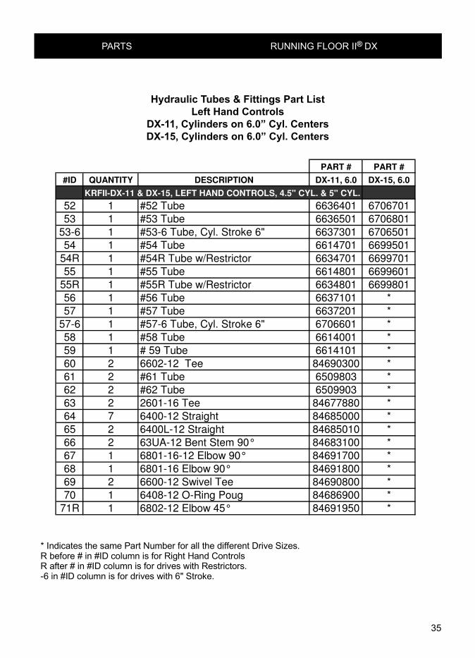
Hydraulic Tubes & Fittings Part ListLeft Hand Controls
DX-11, 3.0" Cyl. on 6.0" Cyl. CentersDX-15, 3.0" Cyl. on 6.0" Cyl. CentersDX-11, 3.5" Cyl. on 6.0" Cyl. CentersDX-15, 3.5" Cyl. on 6.0" Cyl. Centers
p34 66929
* Indicates the same Part Number for all the different Drive Sizes.R before # in #ID column is for Right Hand ControlsR after # in #ID column is for drives with Restrictors.-6 in #ID column is for drives with 6" Stroke.
PART # PART #
#ID QUANTITY DESCRIPTION DX-11, 6.0 DX-15, 6.0
KRFII-DX-11 & DX-15, LEFT HAND CONTROLS, 4.5" CYL. & 5" CYL.
52 1 #52 Tube 6636401 6706701
53 1 #53 Tube 6636501 6706801
53-6 1 #53-6 Tube, Cyl. Stroke 6" 6637301 6706501
54 1 #54 Tube 6614701 6699501
54R 1 #54R Tube w/Restrictor 6634701 6699701
55 1 #55 Tube 6614801 6699601
55R 1 #55R Tube w/Restrictor 6634801 6699801
56 1 #56 Tube 6637101 *
57 1 #57 Tube 6637201 *
57-6 1 #57-6 Tube, Cyl. Stroke 6" 6706601 *
58 1 #58 Tube 6614001 *
59 1 # 59 Tube 6614101 *
60 2 6602-12 Tee 84690300 *
61 2 #61 Tube 6509803 *
62 2 #62 Tube 6509903 *
63 2 2601-16 Tee 84677880 *
64 7 6400-12 Straight 84685000 *
65 2 6400L-12 Straight 84685010 *
66 2 63UA-12 Bent Stem 90° 84683100 *
67 1 6801-16-12 Elbow 90° 84691700 *
68 1 6801-16 Elbow 90° 84691800 *
69 2 6600-12 Swivel Tee 84690800 *
70 1 6408-12 O-Ring Poug 84686900 *
71R 1 6802-12 Elbow 45° 84691950 *
Hydraulic Tubes & Fittings Part ListLeft Hand Controls
DX-11, Cylinders on 6.0” Cyl. CentersDX-15, Cylinders on 6.0” Cyl. Centers

36
PARTS RUNNING FLOOR II® DX
View from underneath
Front ofTrailer
Left SideRight Side
DX15
65
On/Off Ball Valve(see page 47)
(Check Valve Adaptor Block)
R52
R53
With or WithoutRestrictors(see p age 37)
Hydraulic Tubes & Fittings forRight Hand Controls
(see page 37 - 39)
DX11
57
SwitchingValve(see page45 & 46)
56
R53
57
R55
R54
56
R52On/Off Ball Valve Handle(see page 53-55)
616962
Control ValveHandle(see page 53-55)
63 63
59 58
62
7961
(Check Valves)(see page 40 & 42)
ControlValve(see page 43 & 44)
58
59
62
6169
(Check Valves)
Check Valve Adaptor Block(see page 41 & 42)
59
75
76
75
80

37
PARTS RUNNING FLOOR II® DX
DETAIL FSCALE 1/5 DETAIL GSCALE 1/5
FG
R55
57R53
59
View from underneath
p36-66929
Control Valve(see page 43 & 44)
Without Restrictors With Restrictors
Hydraulic Tubes & Fittings forRight Hand Controls
With or Without Restrictors(see pages 38 & 39)
60
66
66
64
60
R54
56
64 58
68
67
70
R53
R52
57 R53
R53
R52
64
56
Restrictors(see page 50)
R54R
R55R
Switching Valve(see page 45 & 46)
70
67
68
71
64

38
PARTS RUNNING FLOOR II® DX
p37 66929
* Indicates the same Part Number for all the different Drive Sizes.R before # in #ID column is for Right Hand ControlsR after # in #ID column is for drives with Restrictors.-6 in #ID column is for drives with 6" Stroke.
PART # PART # PART # PART #
KRFII-DX-11 & DX-15, Right Hand Controls, 4.5" Cyl. & 5.0: Cyl.
#ID QUANTITY DESCRIPTION DX-11, 4.5 DX-15, 4.5 DX-11 5.0 DX-15 5.0
R52 1 #R52 Tube 6640301 6699901 6707401 6708001
R53 1 #R53 Tube 6640401 6700001 6707501 6708101
R53-6 1 #R53-6 Tube Cyl Stroke 6" 6640901 6641001 6708601 6708701
R54 1 #R54 Tube 6640701 6700101 6640701 6700101
R54R 1 #R54R Tube w/Restrictor 6640501 6700301 6640501 6700301
R55 1 #R55 Tube 6640801 6700201 6640801 6700201
R55R 1 #R55R Tube w/Restrictor 6640601 6700401 6640601 6700401
56 1 #56 Tube 6649101 6649101 6628901 6628901
57 1 #57 Tube 6614401 6614401 6629001 6629001
57-8 1 #57-8 Tube Cyl Stroke 8" 6734701
57-6 1 #57-6 Tube Cyl Stroke 6" 6630701 6630701 6650101 6650101
58 1 #58 Tube 6614001 * * *
59 1 #59 Tube 6614101 * * *
60 2 6602-12 Tee 84690300 * * *
61 2 #61 Tube 6509801 6509801 6509802 6509802
62 2 #62 Tube 6509901 6509901 6509902 6509902
63 2 2601-16 Tee 84677880 * * *
64 7 6400-12 Straight 84685000 * * *
65 1 6400L-12 Straight 84685010 * * *
66 2 63UA-12 Bent Stem 90%%d 84683100 * * *
67 1 6801-16-12 Elbow 90%%d 84691700 * * *
68 1 6801-16 Elbow 90%%d 84691800 * * *
69 2 6600-12 Swivel Tee 84690800 * * *
70 1 6408-12 O-Ring Plug 84686900 * * *
71R 2 6802-12 Elbow 45° 84691950 * * *
Hydraulic Tubes & Fittings Part ListRight Hand Controls
DX-11, Cylinders on 4.5” Cyl. CentersDX-15, Cylinders on 4.5” Cyl. CentersDX-11, Cylinders on 5.0” Cyl. CentersDX-15, Cylinders on 5.0” Cyl. Centers

39
PARTS RUNNING FLOOR II® DX
p38 66929
* Indicates the same Part Number for all the different Drive Sizes.R before # in #ID column is for Right Hand ControlsR after # in #ID column is for drives with Restrictors.-6 in #ID column is for drives with 6" Stroke.
PART # PART #
KRFII-DX-11 & DX-15, Right Hand Controls. 6.0" CC
#ID QUANTITY DESCRIPTION DX-11 6.0 DX-15, 6.0
R52 1 #R52 Tube 6708801 6709501
R53 1 #R53 Tube 6708901 6709601
R53-6 1 #R53-6 Tube Cyl. Stroke 6" 6706001 6709701
R54 1 #R54 Tube 6640701 6700101
R54R 1 #R54R Tube w/Restrictor 6640501 6700301
R55 1 #R55 Tube 6640801 6700201
R55R 1 #R55R Tube 6640601 6700401
56 1 #56 Tube 6637101 *
57 1 #57 Tube 6637201 *
57-6 1 #57-6 Tube Cyl. Stroke 6" 6706601 *
58 1 #58 Tube 6614001 *
59 1 #59 Tube 6614101 *
60 2 6602-12 Tee 84690300 *
61 2 #61 Tube 6509803 *
62 2 #62 Tube 6509903 *
63 2 2601-16 Tee 84677880 *
64 7 6400-12 Straight 84685000 *
65 1 6400L-12 Long Straight 84685010 *
66 2 63UA-12 Bent Stem 90° 84683100 *
67 1 6801-16-12 Elbow 90° 84691700 *
68 1 6801-16 Elbow 90° 84691800 *
69 2 6600-12 Swivel Tee 84690800 *
70 1 6408-12 O-Ring Plug 84686900 *
71R 2 6802-12 Elbow 45° 84691950 *
Hydraulic Tubes & Fittings Part ListRight Hand Controls
DX-11, Cylinder on 6.0” Cyl. CentersDX-15, Cylinder on 6.0” Cyl. Centers

40
PARTS RUNNING FLOOR II® DX
78
83
84
8592
86
8988
87
90
93
Cylinder Rod
91
97
Hydraulic Tubes
96
95Assembled Check Valve
Tubes and Clamps
Check Valve Assembly
p19-39 66914A
77
Assembled Check Valve
98
p19-39 66914A

41
PARTS RUNNING FLOOR II® DX
95
96
91
97
Assembled Check Valve Adaptor Block with Tubes and Clamps
Assembled Check Valve Adaptor Block
Check Valve Adaptor Block Assembled
p41 67119C
Cylinder Rod
Hydraulic Tube
82
93
81
98
p41 67119C

42
PARTS RUNNING FLOOR II® DX
Check Valve Assembly andCheck Valve Adaptor Block Assembly
p41 66915
#ID QUANTITY DESCRIPTION PART NUMBER
Check Valve Assembly Parts List
77 1 Check Valve External Assembly (no connecters) 06520103- - Includes items 78, 83-92 -
78 1 Body Check Valve External 0660290181 1 Check Valve Adaptor Block Assembly (no connectors) 06613503- - Includes items 82, 86, 90, 91, 92 -
82 1 Body Check Valve Adaptor Block 0661340183 1 Plunger Check Valve External 0177110184 1 Rod Check Valve External 0176690185 1 Spring Check Valve External Large #B-18273 8445340086 1 Seal Kit Check Valve External 03878101- Includes Items 87-92 -
87 1 Dust Boot Check Valve External 8480110088 1 Plunger Wiper Check Valve External 8442680089 1 Seal Rod 5/8" Check Valve External 8435220090 2 O-Ring 122 8437780091 2 O-Ring 912 8438740092 1 O-Ring 916 8438780093 1 Clamp Top Check Valve External 0251300195 4 Bolt Socket 5/16" x 4 1/2" 8463251196 4 Washer High Collar Lock 5/16" 8655300197 1 or 2 Staight Threaded Connector W/O-Ring 912 8468500098 1 Long St. Threaded Connector W/O-Ring 912 84685010

43
PARTS RUNNING FLOOR II® DX
Control Valve Assembly
102
105106
104
107
103
110
109108
111
112
105106113
117
116115
109
108
114

44
PARTS RUNNING FLOOR II® DX
Control Valve Assembly
ID # QUANTITY DESCRIPTION PART NUMBER
Control Valve Assembly
102 1 Control Valve Load/Unload Assembly 02552701
- - Includes items 103-109 -
103 1 Body Control Valve 01049501
104 1 Spool Control Valve 03423201
- 1 Seal Kit Control Valve Load/Unload 03877901
- - Includes items 105-107 -
105 2 O-Ring 214 B-70 84381800
106 2 Wiper 1" Rod 84427000
107 1 Snap Ring 2-Piece For Spool 84801000
108 4 6400-12-10 Straight 84684900
109 4 O-Ring 910 84387200
110 2 Bolt Hex GR5 3/8"x3" 86442000
111 2 Washer Lock 3/8" 86555000
112 2 Nut Hex 3/8" 86628500
113 1 Handle Plate 06728001
114 1 Handle Assembly Control Valve Load/Unload -
See pages 53, 54 and 55 Includes Items 115-117
115 1 Handle -
116 1 Nut Hex 3/8" 86628500
117 1 Washer Lock 3/8" 86555000

45
157159
158
156 160
150159
148
139
138125
132
155
123
140
129
136
134
133127
131
130
128
124128
130 127134133
141136
136153137
142
158157
159
156159
160
154
139138
148
149
160
126
132
Switching Valve Assembly
ID # QUANTITY DESCRIPTION PART NUMBER
Switching Valve Assembly
123(1)
1 Switching Valve Assembly SAE 03888901
- - Includes Items 124-154 -
124(1)
1 Body Switching Valve 04504601
125(1)
1 End Cap Right Switching Valve 04504701
126(1)
1 End Cap Left Switching Valve 04504801
127 2 Poppet Switching Valve 03718901
128 2 Ring Poppet Switching Valve 03718801
129 1 Rod Control Switching Valve 01335501
-(2)
1 Seal Kit Switching Valve 03878001
- - Includes items 130-139 -
130 1 O-Ring 111 84376200
(1) Part numbers vary for Switching Valves made before 1998.
(2) The Switching Valve Seal Kit contains all necessary components to rebuild all Switching Valve models.
PARTS RUNNING FLOOR II® DX

46
PARTS RUNNING FLOOR II® DX
Switching Valve Assembly
131 3 O-Ring 117 84377000
132 2 O-Ring 126 84378200
133 2 O-Ring 216 84382200
134 2 O-Ring Backup 8-216 84391600
135 2 O-Ring 908 84387000
136 4 O-Ring 912 84387400
137 1 O-Ring 916 84387800
138 2 Seal Rod 5/8" 84352200
139 2 Wiper Canned 5/8" Rod 84427200
140 2 6400-12-12 Straight 84685000
141 1 6408-12 M O-Ring Socket Plug 84687700
142 1 6801-16-16 Straight Thread Elbow 84691800
144 2 6408-08 M O-Ring Socket Plug 84687500
146 2 Spring S157 84451750
147 2 Filter Element CF0563-46 84012700
148 5 Bolt Hex GR5 3/8"x2 1/2" 86441000
149 3 Bolt Hex GR5 3/8"x3" 86442000
150 1 Cap Limit Switching Valve 02552101
153 1 6801-16-12 Straight Thread Elbow 84691700
154 1 Washer Large OD 3/8" 86553500
155 2 Rod Threaded Assembly Switching Valve 03869701
- - Includes Items 156-160 -
156 1 Threaded Rod 3/8"x18" 86603000
157 1 Switching Valve Grommet 83217500
158 2 Washer Large OD 3/8" 86553500
159 3 Nut Hex 3/8" 86628500
160 1 Washer Lock 3/8" 86555000
47
PARTS RUNNING FLOOR II® DX
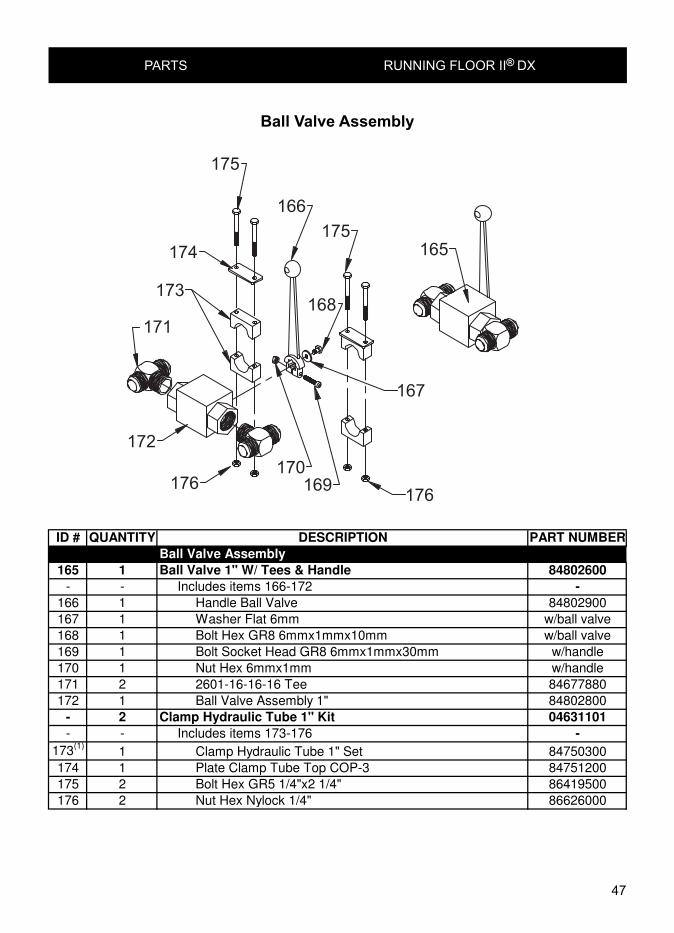
Ball Valve Assembly
ID # QUANTITY DESCRIPTION PART NUMBER
Ball Valve Assembly
165 1 Ball Valve 1" W/ Tees & Handle 84802600
- - Includes items 166-172 -
166 1 Handle Ball Valve 84802900
167 1 Washer Flat 6mm w/ball valve
168 1 Bolt Hex GR8 6mmx1mmx10mm w/ball valve
169 1 Bolt Socket Head GR8 6mmx1mmx30mm w/handle
170 1 Nut Hex 6mmx1mm w/handle
171 2 2601-16-16-16 Tee 84677880
172 1 Ball Valve Assembly 1" 84802800
- 2 Clamp Hydraulic Tube 1" Kit 04631101
- - Includes items 173-176 -
173(1)
1 Clamp Hydraulic Tube 1" Set 84750300
174 1 Plate Clamp Tube Top COP-3 84751200
175 2 Bolt Hex GR5 1/4"x2 1/4" 86419500
176 2 Nut Hex Nylock 1/4" 86626000

48
PARTS RUNNING FLOOR II® DX
BALLVALVE
THE SWITCHINGPRESSURE TO
VALVE
FROM THEPRESSURE
PUMP
RETURNTO THETANK
VALVE
RETURN FROMTHE SWITCHING
SOLENOIDVALVE
2 1
HYDRAULIC SCHEMATIC
ON OFF
GROUND
+12 VDC
SWITCH
SOLENOIDCOIL
WIRING DIAGRAM
(NOTSUPPLIED)
OTHER VOLTAGESAVAILABLE
PRESSUREFROM THE
PUMP
RETURNTO THETANK
PRESSURE TOTHE SWITCHING
VALVE
RETURN FROMTHE SWITCHING
VALVE
171
166172
167168
169
170190
192
191
194
193
196195
197
200
201
198
198
190
INSTALLATIONREMOVE THE EXISTING BALL VALVE. THE BALL VALVEIS MOUNTED ON THE FRONT OF THE DRIVE FRAMEON THE DRIVERS SIDE. THE BALL VALVE IS MOUNTEDBETWEEN THE PRESSURE AND RETURN LINES.INSTALL THE ELECTRICAL ON/OFF CONTROL ASSEMBLY.CONNECT THE PRESSURE AND RETURN LINES AS SHOWN.SUPPLY ELECTICAL POWER TO THE SOLINOID. INSTALLA SWITCH IN THE ELECTRICAL SUPPLY COIL. RUN THE WIRINGIN WATER-TIGHT FLEX CONDUIT. OPERATIONSHIFT THE BALL VALVE HANDLE TO THE OPEN POSITION.SET THE ELECTRICAL SWITCH TO THE OFF POSITION.ENGAGE THE PTO TO START THE HYDRAULIC PUMP.SWITCH THE ELECTRICAL SWITCH TO THE ON POSITIONTO START THE WALKING FLOOR.THE SOLENOID COIL MUST BE ENERGIZED FOR THEWALKING FLOOR TO RUN.TO START OR STOP THE FLOOR AT THE DRIVE USINGTHE BALL VALVE.- SET ELECTICAL SWITCH TO THE OFF POSITION.- CLOSE THE BALL VALVE TO START THE WALKING FLOOR. OPEN THE BALL VALVE TO STOP THE WALKING FLOOR.
p48-67398A
ELECTRIC ON/OFF BALL VALVE ASSEMBLY
197199
195

49
PARTS RUNNING FLOOR II® DX
#ID QUANTITY DESCRIPTION PART NUMBER
ELECTRIC ON/OFF BALL VALVE PARTS LIST
166 1 Handle Ball Valve 84802900
167 1 Washer Flat 6mm w/ball valve
168 1 Bolt Hex GR8 6mm x 1mm x 10mm w/ball valve
169 1 Blot Socket Head GR8 6mmx1mmx30mm w/handle
170 1 Nut Hex 6mm x 1mm w/handle
171 1 2601-16-16-16 Tee 84677880
172 1 Ball Valve Assembly 1" 84802800
190 1 Electric On/Off Ball Valve Assembly 3426601
Includes items 191 & 192
191 1 Manual On/Off Ball Valve Assembly 84802601
Includes items 166 - 172 & 193
192 1 Electric Soleniod Valve Assembly 85108200
Includes items 194 - 196
193 1 2501-16-16 Male Elbow 84677400
194 1 Body Valve 20822 566409 2-Way 85101600
195 1 Valve Cartridge SV3-20-0-0-00 85108120
196 1 Coil, 12 VDC w/Lead Wire MC 30545 85600300
197 1 6402-16-16 Swivel St. Thread Connector 84686200
198 2 916 Buna-90 O-Ring 84387800
199 1 2603-16-16-16 Union Tee 84678100
200 1 63UA-16-16 Bent Stem 90 Deg. 84683200
201 1 63UC-16-16 Long Bent Stem 90 Deg. 84683700

50
PARTS RUNNING FLOOR II® DX
Restrictor Valve Assembly
Trstrictor Valve Parts List#ID Quantity Description Part Number220 1 Restrictor Valve Assembly with Fittings 06549901
- - Includes items 256 - 269 -221 1 Restrictor Valve Assembly without Fittings 06549902
- - Includes items 257 - 266 -222 1 Restrictor Valve Body 06549601223 1 Restictor Rod End Cap Spring End 03349001224 1 Spring Danly Yellow 84455400225 1 Restrictor Rod 03348901226 1 Restrictor Valve 01951901227 1 Restrictor Rod End Cap Small End 03349101228 1 6400-12-12 Straight Connector 84685000229 1 6402-12-12 Swivel Straight Thread 84686100230 2 6408-H-8 Hollow Hex Plug 84687500231 2 908 O-Ring 84387000232 6 912 O-Ring 84387400233 1 6408-H-12 Hollow Hex Plug 84687700234 1 6802-12-12 45 Straight Thread Elbow 84691950235 1 6400-12-12 Straight Connector 84685000
Restrictor Valve #185 is used in 3 differentconfigurations 185-A, -B & -C. This is done by replacing fittings 198 or 199 & 200. Restrictor valve185-A is used as front restrictor, restrictor valve 185-Bis used as front restrictor on right hand DX-11 and restrictorvalve 185-C is used as rear restrictor.
p50-67182A
234 220A 235 220-B 220-C 234
221
232
224
230231
222232
234228
223225
226223
232
231
230
228232
227
232229
#ID QUANTITY DESCRIPTION PART NUMBER
Restrictor Valve Parts List
220 1 Restrictor Valve Assembly with Fittings 6549901
- - Includes items 256 - 269 -
221 1 Restrictor Valve Assembly without Fittings 6549902
- - Includes items 257 - 266 -
222 1 Restrictor Valve Body 6549601
223 1 Restictor Rod End Cap Spring End 3349001
224 1 Spring Danly Yellow 84455400
225 1 Restrictor Rod 3348901
226 1 Restrictor Valve 1951901
227 1 Restrictor Rod End Cap Small End 3349101
228 1 6400-12-12 Straight Connector 84685000
229 1 6402-12-12 Swivel Straight Thread 84686100
230 2 6408-H-8 Hollow Hex Plug 84687500
231 2 908 O-Ring 84387000
232 6 912 O-Ring 84387400
233 1 6408-H-12 Hollow Hex Plug 84687700
234 1 6802-12-12 45° Straight Thread Elbow 84691950
235 1 6400-12-12 Straight Connector 84685000

51
PARTS RUNNING FLOOR II® DX
U1
L1 P2L3
A
U3 P1
B
Electric Load/Unload Control Valve
252
253
254
255
256257
258
259
260256257
258
259
260
261262
263
264265
262263
266267
266267
268
269
251
270
270
254
254271
p51-67425
250

52
PARTS RUNNING FLOOR II® DX
#ID QUANTITY DESCRIPTION PART NUMBER
ELECTRIC LOAD/UNLOAD CONTROL VALVE PARTS LIST
250 1 Electric Load/Unload Control Valve Assembly 3244601
Includes items 251-269
251 1 Electric ControlValve Body 3134701
252 4 Pilot Oeperated Check Valve 3138401
253 4 Ext Check Valve Spring Large 84453400
254 10 912 O-Ring 84387400
255 4 -12 Pilot Operated Spring End Cap 3860201
256 4 8-213 O-Ring 84391200
257 4 213 O-Ring 84381200
258 4 Plunger Pilot Operated Check Valve 3123601
259 4 916 O-Ring 84387800
260 4 6409-16 MSAE O-Ring Socket Plug 84687900
261 1 Shuttle Valve LS04-B-30-0-N 85104800
262 3 904 O-Ring 84386600
263 3 6409-04 MSAE O-Ring Socket Plug 84687400
264 2 5/16" Chrome Steel Ball 84800500
265 2 I-9 Spring 84450800
266 2 906 O-Ring 84386800
267 2 6409-06 MSAE O-Ring Socket Plug 84687400
268 1 SV-10-40M-12DG Solenoid Valve 85108600
269 1 Coil 115 Dac Din 6366115 85600650
270 4 6400-12-12 MSAE-MJIC Straight Connector 84685000
271 2 6802-12-12 MSAE-MJIC 45 Deg Elbow 84691975

53
PARTS RUNNING FLOOR II® DX
13"17" 13" 17"
View from rear
p53-67180B
View from underneath
Dimensions are approximate, different drives can very by 1-1/4" depending on Cross-Member Height
Left Side Right Side
13" dimension is DX11 17" dimension is DX15
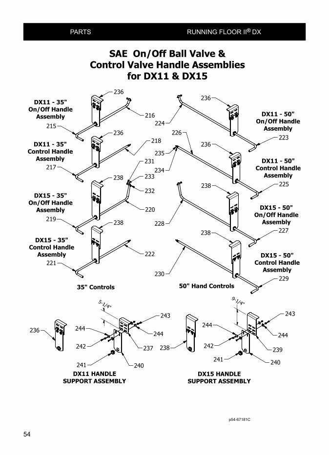
SAE On/Off Ball Valve &Control Valve Handle Assemblies
for DX11 & DX15
219215
221217
227223
229225
54
PARTS RUNNING FLOOR II® DX
SAE On/Off Ball Valve &Control Valve Handle Assemblies
for DX11 & DX15
DX11 - 35"On/Off Handle
Assembly
DX11 - 35"Control Handle
Assembly
DX15 - 35"On/Off Handle
Assembly
DX15 - 35"Control Handle
Assembly
35" Controls 50" Hand Controls
DX11 - 50"On/Off Handle
Assembly
DX11 - 50"Control Handle
Assembly
DX15 - 50"On/Off Handle
Assembly
DX15 - 50"Control Handle
Assembly
9-1/4"
p54-67181C
5-1/4"
215
217
219
221
236
236
238
238
216
218
220
222
232
231
233234
235
224226
228
230
236
236
238
238
223
225
227
229
236
240241
242
244
237
244
243
238
240241
242
244
239
244
243
DX11 HANDLESUPPORT ASSEMBLY
DX15 HANDLESUPPORT ASSEMBLY
p54-67181C

55
PARTS RUNNING FLOOR II® DX
#ID QUANTITY DESCRIPTION PART NUMBER
215 1 DX11 - 35" On/Off Ball Valve Handle Assembly 6625501
- - Included items 216, 231-233 & 236 -
216 1 DX11 - 35" On/Off Ball Valve Handle 6625101
217 1 DX11 - 35" Control Valve Handle Assembly 6627301
- - Included items 218, 234, 235 & 236 -
218 1 DX - 35" Control Valve Handle 6714801
219 1 DX15 - 35" On/Off Ball Valve Handle Assembly 6698601
- - Included items 220, 231-233 & 238 -
220 1 DX15 - 35" On/Off Valve Handle 6698801
221 1 DX15 - 35" Control Valve Handle Assembly 6698701
- - Included items 222, 234, 235 & 238 -
222 1 DX - 35" Control Valve Handle 6714801
223 1 DX11 - 50" On/Off Ball Valve Handle Assembly 6712901
- - Included items 224, 231-233 & 236 -
224 1 DX11 - 50" On/Off Valve Handle 6713001
225 1 DX11 - 50" Control Valve Handle Assembly 6712501
- - Included items 226, 234, 235 & 236 -
226 1 DX - 50" Control Valve Handle 6747601
227 1 DX15 - 50" On/Off Ball Valve Handle Assembly 6713101
- - Included items 228, 231-233 & 238 -
228 1 DX15 - 50" On/Off Valve Handle 6713201
229 1 DX15 - 50" Control Valve Handle Assembly 6712701
- - Included items 230, 234, 235 & 238 -
230 1 DX - 50" Control Valve Handle 6747601
231 1 Bolt Hex GR5 5/16" x 1-3/4" 86428500232 1 Nut Hex Nylock 5/16" 86627500
233 3 Washer Flat 5/16" 86552500
234 1 Nut Hex 3/8" 86628500
235 1 Washer Lock 3/8" 86555000
236 1 DX11 Handle Support Assembly 6627101
- - Included items 237, 240-244 -
237 1 DX11 Angle Mount Plate 6625401
238 1 DX15 Handle Support Assembly 6747801
- - Included items 239, 240-244 -
239 1 DX15 Angle Mount Plate 6698501
240 1 On/Off & Control Valve Handle Mount Plate 3690401
241 1 Groumet Handle Support 83218400
242 2 Bolt Hex GR5 3/8" x 1-1/4" 86428500
243 2 Nut Hex Nylock 3/8" 86628000
244 4 Washer Flat 3/8" 86554000
On/Off Ball Valve & Control Valve Handle Assemblies DX11 & DX15

56
PARTS RUNNING FLOOR II® DX
Front Shield Assembly
261
260
268269
264 266
267
265
(1) Part numbers and descriptions vary based on trailer width and application.
(2) Quantity varies based on trailer width and application.
ID # QUANTITY DESCRIPTION
FRONT SHIELD ASSEMBLY
-1 1 Front Shield 96” Wide Assembly
- - Includes items 182-189
260(1)
1 Front Shield 96” Wide 14 Gauge
261(1)
1 Bearing Strip Front Shield 1/4”x2 7/8”
264 5 Stiffener Angle Front Shield 1 1/2"x 1 1/2"x3/16”
265 25 Rivet 3/16”x1/2”
266 10 Nut Hex 10mm
267 10 Washer Lock 10mm
268 10 Bolt Hex 8.8 10mm x 20mm
269 10 Washer Large OD 3/8”
(1) Part numbers and descriptions vary based on trailer width and application
(2) Quantity varies based on trailer width and application.

57
PARTS RUNNING FLOOR II® DX
Floor Components
ID# QUANTITY DESCRIPTION PART NUMBER
FLOOR COMPONETS
- - Includes items 268, 269, 271-275, 277, 278 -
268(1)
- Floor Bolt Socket Head Dia. & Length are Variable -
269(1)
- Floor Slat #2188 822188SPCL
270(1)
- Nut Hex Nylock -
271(1)
- Seal Floor #1212 83121253
272(1)
- Drive Shoe -
273(1)
- Bearing 3.5" Floor Slat #300308 300308
274(1)(2)
- Aluminum Channel #2469 83246901
275(1)
- Splash Guard Hold-Down Bearing #2468 83246801
(1) Part numbers and descriptions vary based on trailer width and application.(2) Channel is also available in 44’ lengths (8224694400) and 48’ lengths (8224694800)
* The last four digits in a ten part number refers to length in feet and inches (Example 8222954305 is 43’05” long’).
273
269
275
274
268 269
271
270
275 (End View)
p57-67916
Parts ListPart NumberDescriptionQtyItem
-FLOOR COMPONETS--- Includes items 268, 269, 271-275, 277, 278--- Floor Bolt Socket Head Dia. & Length are Variable-268
822188SPCL Floor Slat #2188-269- Nut Hex Nylock -270
83121253 Seal Floor #1212-271- Drive Shoe-272
300308 Bearing 3.5" Floor Slat #300308-27383246901 Aluminum Channel #2469-27483246801 Splash Guard Hold-Down Bearing #2468-275
272

58
PARTS RUNNING FLOOR II® DX
Floor Components
280282
269
283
281
269268
270
283 (End View)
271
p58-67917
Parts ListItem Qty Description Part Number
- - FLOOR COMPONETS -- - Includes items 268-276 -
268 - Floor Bolt Socket Head Dia. & Length are Variable -269 - Floor Slat #2188 822188SPCL270 - Nut Hex Nylock -271 - Seal Floor #1212 83121253272 - Drive Shoe -280 - Bearing 3.5" #3003 300301281 - Subdeck 1" x 1" x .063" x 20' Steel Tube 80300200282 - Bearing Hold-Down 3.5" Floor Slat #3004 300401283 - Splash Guard Bearing (Not Hold Down) #2228 83222801
272#ID QUANTITY DESCRIPTION
FLOOR COMPONETS
- - Includes items 268-276
268(1)
- Floor Bolt Socket Head Dia. & Length are Variable
269(1)
- Floor Slat #2188
270(1)
- Nut Hex Nylock
271(1)
- Seal Floor #1212
272(1)
- Drive Shoe
280(1)
- Bearing 3.5" #3003
281(1)
- Subdeck 1" x 1" x .063" x 20' Steel Tube
282(1)
- Bearing Hold-Down 3.5" Floor Slat #3004
283(1)
- Splash Guard Bearing (Not Hold Down) #2228
(1) Part numbers and descriptions vary based on trailer width and application.
* The last four digits in a ten part number refers to length in feet and inches (Example 8222954305 is 43’05” long’).

59
MAINTENANCE RUNNING FLOOR II® DX
1. For proper operation of your new RUNNING FLOOR II® DX equipped trailer and wet kit, make sure the pressure and return lines are hooked up correctly. It is important to periodically inspect hoses and connectors for damage and contamination. Clean all dirt and water from connectors before hooking up.2. Change the hydraulic return filter element after the first six (6) hours of operation and then every six (6) months. This may vary with the operating environment.3. During the first two (2) weeks of operation, it will be necessary to check and tighten all floor bolts. Floor bolts should be checked regularly for proper torque, in accordance with a preventive maintenance program, as loose floor bolts will cause serious damage to floor slats.4. After the first week of operation, you must check and tighten the lower cross-drive clamp bolts that fasten the cross-drives to the cylinder. Also check the end cylinder rod plate bolts that fasten the cylinders to the drive frame.5. During the first several weeks of operation, examine the check valve and tube clamps regularly to ensure that they are securely fastened.6. It is recommended to pressure wash the top of the floor slats and seal every six months.
Problems and Trouble-ShootingKEITH Mfg. Co. 24-hour Fax Service (541) 475-2169KEITH Mfg. Co. Customer Service and Support (800) 547-6161 or (541) 475-3802Monday - Friday, 7 am to 4 pm Pacific Standard TimeEmail: [email protected]
Before you call, please review the following:1. See start-up check list on page 11. Re-checking items on this list can solve most problems.2. We will be better able to help solve any problems if you have the information indicated below before you call.
a. Drive Model Number d. Trailer makeb. Drive Serial Number e. Cylinder bore sizec. Number of floor slats
Bolt Description Recommended Bolt Torque Values TorqueBolt Floor 5/16” FHCS 82° flat head floor bolt 22 FT-LBSBolt Floor 3/8” FHCS 82° flat head floor bolt 42 FT-LBSBolt Hex 5/8” HCS Lower cross-drive clamp bolt
(Over torque may distort the barrel enough to bind the piston.)
135 FT-LBS
Bolt Hex 5/8” HCS Rod end plates 135 FT-LBSBolt Hex 5/16” HCS Check valve and tube clamp bolts 20 FT-LBS
Maintenance For Your New KEITH® RUNNING FLOOR II® DX and Hydraulic Wet Kit

60
PLEASE FILL OUT AND RETURN IMMEDIATELY TO KEITH Mfg. Co.
PurchaserAddress PhoneCity State/Prov.Country Postal CodeOriginal Purchase Date of SystemKEITH Model No.KEITH Serial No. (See page 9, 10 for location guide)
Installed in: New Trailer Used TrailerDealer Name & LocationType of Material Unloaded
I have fully read the KEITH Mfg. Co. warranty information and I/we fully understand and agree to the terms of the warranty.
Signature Date
Note: To validate the warranty, this registration card must be filled out completely and returned to KEITH Mfg. Co. within ten (10) days of purchase and/or installation.
Please fax, mail or email this warranty registration information to KEITH Mfg. Co. at:
Warranty Registration KEITH Mfg. Co. P.O. Box 1 Madras, OR 97741-0001 Fax: (541) 475-2169 Email: [email protected]
CU
T H
ERE
The warranty registration card must be completed and on file at KEITH Mfg. Co. in order for the warranty period to begin on the purchase date. If no purchase date is registered, the beginning of the warranty will be the date of the manufacture if no other date can be determined.
Please make sure the serial number listed on the card coincides with the serial number plate on the drive unit.
Please print or typeKEITH® RUNNING FLOOR II® DX Warranty Registration Card

61
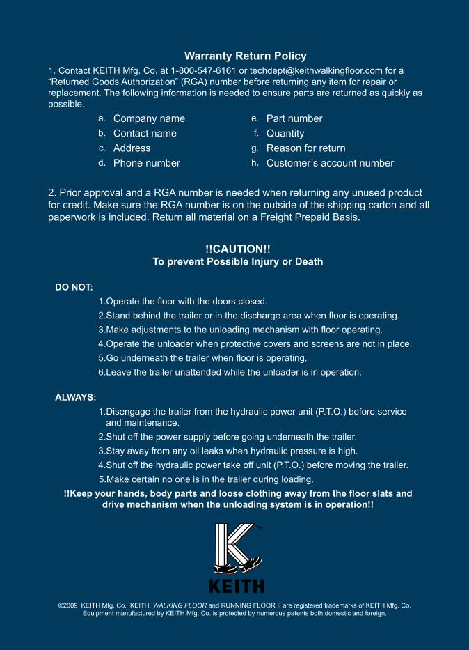
62
©2009 KEITH Mfg. Co. KEITH, WALKING FLOOR and RUNNING FLOOR II are registered trademarks of KEITH Mfg. Co.Equipment manufactured by KEITH Mfg. Co. is protected by numerous patents both domestic and foreign.
!!CAUTION!!To prevent Possible Injury or Death
DO NOT:1.Operate the floor with the doors closed.2.Stand behind the trailer or in the discharge area when floor is operating.3.Make adjustments to the unloading mechanism with floor operating.4.Operate the unloader when protective covers and screens are not in place.5.Go underneath the trailer when floor is operating.6.Leave the trailer unattended while the unloader is in operation.
ALWAYS:1.Disengage the trailer from the hydraulic power unit (P.T.O.) before service
and maintenance.2.Shut off the power supply before going underneath the trailer.3.Stay away from any oil leaks when hydraulic pressure is high.4.Shut off the hydraulic power take off unit (P.T.O.) before moving the trailer.
5.Make certain no one is in the trailer during loading.!!Keep your hands, body parts and loose clothing away from the floor slats and
drive mechanism when the unloading system is in operation!!
Warranty Return Policy1. Contact KEITH Mfg. Co. at 1-800-547-6161 or [email protected] for a “Returned Goods Authorization” (RGA) number before returning any item for repair or replacement. The following information is needed to ensure parts are returned as quickly as possible.
a. Company name e. Part numberb. Contact name f. Quantityc. Address g. Reason for returnd. Phone number h. Customer’s account number
2. Prior approval and a RGA number is needed when returning any unused product for credit. Make sure the RGA number is on the outside of the shipping carton and all paperwork is included. Return all material on a Freight Prepaid Basis.